EP3551027B1 - Machine de séchage de vaisselle ou assimilé et procédé de séchage de vaisselle ou assimilé avec ladite machine - Google Patents
Machine de séchage de vaisselle ou assimilé et procédé de séchage de vaisselle ou assimilé avec ladite machine Download PDFInfo
- Publication number
- EP3551027B1 EP3551027B1 EP17811544.0A EP17811544A EP3551027B1 EP 3551027 B1 EP3551027 B1 EP 3551027B1 EP 17811544 A EP17811544 A EP 17811544A EP 3551027 B1 EP3551027 B1 EP 3551027B1
- Authority
- EP
- European Patent Office
- Prior art keywords
- heat transfer
- transfer fluid
- coil condenser
- air
- steam mixture
- Prior art date
- Legal status (The legal status is an assumption and is not a legal conclusion. Google has not performed a legal analysis and makes no representation as to the accuracy of the status listed.)
- Not-in-force
Links
Images


Classifications
-
- A—HUMAN NECESSITIES
- A47—FURNITURE; DOMESTIC ARTICLES OR APPLIANCES; COFFEE MILLS; SPICE MILLS; SUCTION CLEANERS IN GENERAL
- A47L—DOMESTIC WASHING OR CLEANING; SUCTION CLEANERS IN GENERAL
- A47L15/00—Washing or rinsing machines for crockery or tableware
- A47L15/0002—Washing processes, i.e. machine working principles characterised by phases or operational steps
- A47L15/0013—Drying phases, including dripping-off phases
-
- A—HUMAN NECESSITIES
- A47—FURNITURE; DOMESTIC ARTICLES OR APPLIANCES; COFFEE MILLS; SPICE MILLS; SUCTION CLEANERS IN GENERAL
- A47L—DOMESTIC WASHING OR CLEANING; SUCTION CLEANERS IN GENERAL
- A47L15/00—Washing or rinsing machines for crockery or tableware
- A47L15/42—Details
- A47L15/48—Drying arrangements
- A47L15/483—Drying arrangements by using condensers
-
- A—HUMAN NECESSITIES
- A47—FURNITURE; DOMESTIC ARTICLES OR APPLIANCES; COFFEE MILLS; SPICE MILLS; SUCTION CLEANERS IN GENERAL
- A47L—DOMESTIC WASHING OR CLEANING; SUCTION CLEANERS IN GENERAL
- A47L15/00—Washing or rinsing machines for crockery or tableware
- A47L15/0018—Controlling processes, i.e. processes to control the operation of the machine characterised by the purpose or target of the control
- A47L15/0044—Operation time reduction
-
- A—HUMAN NECESSITIES
- A47—FURNITURE; DOMESTIC ARTICLES OR APPLIANCES; COFFEE MILLS; SPICE MILLS; SUCTION CLEANERS IN GENERAL
- A47L—DOMESTIC WASHING OR CLEANING; SUCTION CLEANERS IN GENERAL
- A47L15/00—Washing or rinsing machines for crockery or tableware
- A47L15/0018—Controlling processes, i.e. processes to control the operation of the machine characterised by the purpose or target of the control
- A47L15/0047—Energy or water consumption, e.g. by saving energy or water
-
- A—HUMAN NECESSITIES
- A47—FURNITURE; DOMESTIC ARTICLES OR APPLIANCES; COFFEE MILLS; SPICE MILLS; SUCTION CLEANERS IN GENERAL
- A47L—DOMESTIC WASHING OR CLEANING; SUCTION CLEANERS IN GENERAL
- A47L15/00—Washing or rinsing machines for crockery or tableware
- A47L15/42—Details
- A47L15/4246—Details of the tub
-
- A—HUMAN NECESSITIES
- A47—FURNITURE; DOMESTIC ARTICLES OR APPLIANCES; COFFEE MILLS; SPICE MILLS; SUCTION CLEANERS IN GENERAL
- A47L—DOMESTIC WASHING OR CLEANING; SUCTION CLEANERS IN GENERAL
- A47L15/00—Washing or rinsing machines for crockery or tableware
- A47L15/42—Details
- A47L15/4291—Recovery arrangements, e.g. for the recovery of energy or water
-
- A—HUMAN NECESSITIES
- A47—FURNITURE; DOMESTIC ARTICLES OR APPLIANCES; COFFEE MILLS; SPICE MILLS; SUCTION CLEANERS IN GENERAL
- A47L—DOMESTIC WASHING OR CLEANING; SUCTION CLEANERS IN GENERAL
- A47L2401/00—Automatic detection in controlling methods of washing or rinsing machines for crockery or tableware, e.g. information provided by sensors entered into controlling devices
- A47L2401/18—Air temperature
-
- A—HUMAN NECESSITIES
- A47—FURNITURE; DOMESTIC ARTICLES OR APPLIANCES; COFFEE MILLS; SPICE MILLS; SUCTION CLEANERS IN GENERAL
- A47L—DOMESTIC WASHING OR CLEANING; SUCTION CLEANERS IN GENERAL
- A47L2401/00—Automatic detection in controlling methods of washing or rinsing machines for crockery or tableware, e.g. information provided by sensors entered into controlling devices
- A47L2401/19—Air humidity
-
- A—HUMAN NECESSITIES
- A47—FURNITURE; DOMESTIC ARTICLES OR APPLIANCES; COFFEE MILLS; SPICE MILLS; SUCTION CLEANERS IN GENERAL
- A47L—DOMESTIC WASHING OR CLEANING; SUCTION CLEANERS IN GENERAL
- A47L2501/00—Output in controlling method of washing or rinsing machines for crockery or tableware, i.e. quantities or components controlled, or actions performed by the controlling device executing the controlling method
- A47L2501/36—Other output
Definitions
- the present patent application for industrial invention relates to a machine for the drying of dishes or the like, and to a method for the drying of dishes or the like with said machine.
- the invention falls in the field of dishwashers, in particular in the household sector or the like.
- the dishwashers that can be currently found on the market comprise a wash chamber suitable for housing the dishes to be washed, and for containing an air-steam mixture.
- said dishwashers are provided with drying devices for drying the dishes at the end of the washing cycle.
- Said drying devices generally use water from the water mains as cooling liquid of the air-steam mixture.
- some dishwashers comprise a condensing wall disposed in the wash chamber and configured in such a way to condensate the humidity and reduce the steam title of the air-steam mixture contained in the wash chamber.
- the air-steam mixture is drier, but colder; such a condition impairs the drying of the dishes and may cause the condensation of the steam in the wash chamber, with consequent water dripping on the dishes.
- dishwashers are provided with a system of nozzles suitable for spraying cold water to cool an internal wall of the wash chamber, which acts as condensing wall.
- dishwashers which are provided with a high-capacity tank suitable for being filled with cooling water with a single operation.
- Said water is used to cool the air-steam mixture, but the dehumidification of said mixture progressively tends to become less effective because the water stored in the tank is heated, reaching the dew point temperature of the air-steam mixture and therefore losing its condensation capacity.
- EP0978250 discloses a device for drying the dishes provided in a dishwasher with a washing tank suitable for housing the dishes to be washed, and for containing an air-steam mixture.
- Such a device comprises a condensing duct in fluid communication with the washing tank of the dishwasher through a first opening for introducing the air-steam mixture from the washing tank into the condensing duct, and through a second opening for introducing the air-steam mixture from the condensing duct into the washing tank.
- Such a device also comprises a tank suitable for being filled with cold water.
- a tank is provided with a heat exchange wall with bellows-like surface disposed in the condensing duct, in such way that the cold water contained in the tank cools the air-steam mixture that passes through the condensing duct, partially condensing the humidity of said mixture.
- EP1284627 discloses a device for the drying of crockery provided in a dishwasher with a wash tank suitable for housing the crockery to be washed, and for containing an air-steam mixture.
- a device is provided outside the wash tank and comprises a heat exchanger.
- the heat exchanger comprises a water conduit and an air conduit in adjacent position.
- the water conduit is in fluid communication with the water mains, in such a way that the water conduit is fed with cold water.
- the air conduit instead, is in fluid communication with the wash chamber of the dishwasher through a first opening for introducing the air-steam mixture from the wash chamber into the air conduit, and through a second opening for introducing the air-steam mixture from the air conduit into the wash chamber.
- the air conduit is adjacent to the water conduit in such a way that the cold water contained in the water conduit cools the air-steam mixture that passes through the air conduit, partially condensing the humidity of said mixture.
- EP 2687143 discloses a machine for the drying of dishes according to the preamble of claim 1.
- the main purpose of the present invention is to remedy the drawbacks of the prior art by disclosing a machine for the drying of dishes that is capable of dehumidifying the air-steam mixture contained in the wash chamber with low water consumption.
- Another purpose of the present invention is to disclose a machine for the drying of dishes that is capable of recovering and reusing the cooling water in the following washing cycles.
- Another purpose of the present invention is to disclose a machine for the drying of dishes that is capable of guaranteeing a balanced, progressive dehumidification of the air-steam mixture contained in the wash chamber, avoiding a sudden temperature decrease that may impair the drying process.
- the machine of the invention is used for the drying of dishes and the like, and comprises:
- the peculiarity of the machine according to the invention consists in the fact that the heat exchanger comprises a coil condenser provided with a plurality of fins designed in such a way to favor a heat exchange between the air-steam mixture contained in the circulation duct and the heat transfer fluid contained in the heat exchanger.
- the machine of the invention comprises suitable means for changing the heat transfer fluid contained in the heat exchanger several times during a drying cycle, in such a way to determine a progressive dehumidification of the air-steam mixture in a rapid, effective way.
- the term “dishes” refers to all items that are suitable for being used on a table or in the kitchen, such as, for example, crockery, plates, kitchen tools, pans, pots and the like.
- the machine (1) is used for the drying of dishes and comprises a box-type chassis (T) that supports a plurality of covering panels (11, 12, 13, 14), of which a front panel (not shown in the attached figures), a back panel (14), an upper panel (11), a bottom panel (13) and a pair of lateral panels (12).
- Said covering panels (11, 12, 13, 14) define a wash chamber (10) suitable for housing the dishes to be washed and for containing an air-steam mixture.
- the machine (1) also comprises a circulation duct (3) defined by a lateral wall (32).
- the circulation duct (3) in is fluid communication with the wash chamber (10) through a first opening (30) for introducing the air-steam mixture from the wash chamber into the circulation duct (3), and through a second opening (31) for introducing the air-steam mixture from the circulation duct (3) into the wash chamber.
- the first opening (30) is advantageously obtained on the upper panel (11) of the machine, whereas the second opening (31) is advantageously obtained in lower position on one of the two lateral panels (12) of the machine.
- the first opening (30) and the second opening (31) can be obtained in any panel (11, 12, 13, 14) of the machine.
- the circulation duct (3) can have more than one first opening (30) and more than one second opening (31) and that the lateral wall (32) that defines said circulation duct (3) can be obtained in one piece with one or more panels (11, 12, 13, 14) of the machine.
- the machine (1) of the invention comprises extraction means (300) disposed in the wash chamber (10) for extracting the air-steam mixture from the wash chamber (10) and conveying said air-steam mixture in the circulation duct (3) through the first opening (30).
- Said extraction means (300) comprise a fan that is advantageously installed in the proximity of the first opening (30) of the circulation duct or in the proximity of the second opening (31) of the circulation duct.
- said extraction means (300) may comprise two fans, the first one being disposed in the first opening (30) of the circulation duct, and the second one being disposed in the second opening (31) of the circulation duct.
- a heat exchanger (2) is disposed in the circulation duct (3) and is suitable for containing a heat transfer fluid with a lower temperature than the dew point temperature of the air-steam mixture, in such a way to cool the air-steam mixture and partially condensate the humidity of said air-steam mixture.
- said heat transfer fluid consists in mains water with a temperature of approximately 15°C - 20 °C.
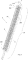
- the heat exchanger (2) comprises a coil condenser (20) comprising a plurality of parallel rectilinear tubes (20a), each of them having a longitudinal axis (X), and a plurality of "U"-shaped coupling tubes (20b), each of them connecting two consecutive rectilinear tubes (20a).
- the coupling tubes (20b) are advantageously made of plastics, rubber, iron or steel.
- each coupling tube (20b) is advantageously connected to two consecutive rectilinear tubes (20a) of the coil condenser (20) in fit-in coupling mode.
- the coupling between the coupling tubes (20b) and the rectilinear tubes (20a) of the coil condenser (20) can be obtained by means of welding if the coupling tubes (20b) are made of iron or steel.
- the volume of said coil condenser (20) is advantageously comprised between 150 cc and 200 cc.
- Each rectilinear tube (20a) of the coil condenser (20) has a diameter comprised between 9 cm and 10 cm, being preferably equal to 9.5 cm, and the center distance between two consecutive rectilinear tubes (20a) of the coil condenser (20) is comprised between 14 cm and 16 cm, being preferably equal to 15 cm.
- such a coil condenser (20) is provided with a plurality of fins (21) in spaced parallel position, each of them having a longitudinal axis (Y) orthogonal to the longitudinal axis (X) of each one of the rectilinear tubes (20a) of the coil condenser (20).
- Each fin (21) comprises holes (21a) for the passage of the rectilinear tubes (20a) of the coil condenser (20).
- Said fins (21) are configured in such a way to favor a heat exchange between the air-steam mixture contained in the circulation duct (3) and the heat transfer fluid contained in the heat exchanger (2).
- the provision of said fins (21) significantly increases the heat exchange surface between the air-steam mixture contained in the circulation duct (3) and the heat transfer fluid contained in the heat exchanger (2). Moreover, because of the special configuration of the heat exchanger (2), the air-steam mixture that flows in the circulation duct (3) hits the fins (21) of the heat exchanger, consequently slowing down the flow of said air-steam mixture in the circulation duct (3), and inevitably cooling the air-steam mixture.
- the coil condenser (20) comprises at least one inlet mouth (200) for the passage of the heat transfer fluid fed in the coil condenser (20), and at least one outlet mouth (210) for the outflow of the heat transfer fluid contained in the coil condenser (20).
- the inlet mouth (200) of the coil condenser is suitable for being connected to the water mains in order to feed cooling water in the coil condenser.
- the outlet mouth (210) of the coil condenser is advantageously connected to a tank (4) disposed in contact with one of the lateral panels (12) of the machine (1) and suitable for containing the heated water that flows out of the coil condenser (20) in such a way that said heated water can be used in the following washing cycles.
- Said heated water requires less energy to be heated to the temperature that are set for the prewashing, washing or rinsing of the dishes, thus increasing the efficiency of the machine (1) and reducing consumption.
- An electrically-controlled normally-closed valve is disposed in the outlet mouth (210) of the coil condenser (20). Said valve advantageously consists in a thermoactuator.
- the heat transfer fluid is fed and stored in the coil condenser (20) in order to be either partially or completely changed when its temperature is proximal to the dew point temperature of the air-steam mixture.
- the temperature of the heat transfer fluid contained in the coil condenser (20) must be always lower than the dew point temperature of the air-steam mixture.
- the machine (1) comprises means configured in such a way to change the heat transfer fluid contained in the coil condenser (20) several times during a drying cycle.
- said means advantageously comprise:
- the temperature sensor can be disposed in the circulation duct (3) to detect the temperature of the air-steam mixture contained in the circulation duct (3).
- the control and processing unit connected to the temperature sensor is configured in such a way to open the valve disposed in the outlet mouth (210) of the coil condenser (20) at a set frequency according to the temperature value of the air-steam mixture contained in the circulation duct (3) detected by the temperature sensor.
- said means configured in such a way to change the heat transfer fluid contained in the heat exchanger (2) several times during a drying cycle, may comprise a timer, or a printed circuit board, connected to the processing and control unit, in such a way that the valve disposed in the outlet mouth (210) of the coil condenser (20) is opened at set time intervals.
- machine (1) of the invention can be also provided with:
- Said method provides for a drying cycle that comprises the following steps:
- the air-steam mixture conveyed in the circulation duct (3) through the first opening (30) travels along the circulation duct (3) grazing the surface of the coil condenser (20) that contains the heat transfer fluid. Consequently, the air-steam mixture is cooled, partially condensing the steam, and the cooled air-steam mixture is introduced from the circulation duct (3) into the wash chamber (10) where it is mixed with the air-steam mixture.
- the machine (1) of the invention permits to progressively and gradually reduce the humidity contained in the air-steam mixture, in such a way that said mixture is partially dehumidified when it is reintroduced into the wash chamber (10), and is capable of absorbing a new quantity of steam, gradually removing the humidity contained in the wash chamber (10) or deposited on the dishes contained therein.
- the process for the drying of dishes with the machine (1) also provides for a changing cycle of the heat transfer fluid contained in the coil condenser (20).
- the changing cycle of the heat transfer fluid is repeated several times during the drying cycle with very short time intervals, each of them with duration of few tens of seconds.
- the machine (1) of the invention provides for short cooling steps, either partially or completely changing the heat transfer fluid contained in the coil condenser (20) on a periodical basis by introducing new cold water, in such a way to obtain the most linear and gradual temperature reduction possible. This avoids the abrupt cooling of the wash chamber (10) that would negatively affect the drying process, for example creating condensation on the dishes.
- the changing cycle of the heat transfer fluid contained in the coil condenser (20) provides for different steps according to the fact that said means, configured in such a way to change the heat transfer fluid contained in the heat exchanger (2) several times during a drying cycle, comprise:
- the changing cycle of the heat transfer fluid contained in the coil condenser (20) provides for the following steps:
- the changing cycle of the heat transfer fluid contained in the coil condenser (20) provides for the following steps:
- the changing cycle of the heat transfer fluid contained in the coil condenser (20) provides for the following steps:
- the changing cycle of the heat transfer fluid contained in the coil condenser (20) provides for sequentially performing, in sequential order:
- the cooling water contained in the coil condenser (20) is the remaining water from the preceding drying cycle, having achieved a temperature of approximately 36°C because it was heated through the walls of the wash chamber (10) by the washing and rinsing process before the drying cycle.
- drying cycle continues with several cooling steps of the water contained in the coil condenser (20), cyclically changing the cooling water contained in the coil condenser (20).
- the changing frequency of the cooling water contained in the coil condenser (20) is reduced.
- the temperature of the wash chamber (10) and, consequently, the heat to be removed from the air-steam mixture have decreased significantly.
- the machine (1) of the invention is not provided with means specifically intended to heat the air-steam mixture.
- the temperature of the last rinse determines the heat that generates the evaporation of the water deposited on the dishes; moreover, because of the cooling of the air-steam mixture, the flow is continuously enriched with steam, being reintroduced in the wash chamber (10) and passing on the dishes.
- the machine (1) of the invention optimizes the drying process by increasing its efficiency also at last rinse temperatures that are much lower than the temperatures measured in the machines of the prior art, i.e. at temperatures of approximately 48-54°C vs. the temperatures measured in the machines of the prior art of approximately 58-60°C, thus contributing to energy saving.
- the machine (1) of the invention significantly reduces the duration of the drying process compared to the time required by the traditional drying machines, which range from 70 to 90 minutes.
- Said water is heated until it has achieved the point (61), which can be identified as one of the upper peaks of said curve 6, wherein the temperature of said cooling water is proximal to the dew point temperature of the air-steam mixture.
- the processing and control unit enables the introduction of new cold water in the coil condenser (20).
- the temperature of the cooling water returns to a new minimum point (60).
- the highest number of changes of the cooling water contained in the coil condenser (20) is concentrated in the second step of the drying process, which can be identified with said section ⁇ t2 of the curves shown in Figs. 5, 6 and 7 .
- Such a higher number of changes of the cooling water contained in the coil condenser (20) is due to the fact that the quantity of cooling water stored in the coil condenser (20) is very limited, ranging, for example, from 100 cl to 600 cl according to the type of machine, in such a way to remove moderate amounts of heat from the air-steam mixture, avoiding the sudden cooling of the wash chamber (10).
- the machine (1) of the invention in fact, performs a dehumidification process through a number of cooling steps of the air-steam mixture characterized by sequential removals of limited amounts of heat.
- Such cooling is implemented by dividing the mass of the cooling water that is necessary to condensate the desired steam, in successive filling/emptying cycles of the coil condenser (20).
- the water consumption for the drying (or dehumidification) process is significantly reduced and the sudden cooling of the wash chamber (10) is prevented.
- the changing steps of the cooling water contained in the coil condenser (20) allow for:
- the machine (1) of the invention provides for treating the air-steam mixture inside the circulation duct (3) of the machine, preventing any dispersion or emission of steam or humidity outside the machine (1).
- the flow of air-steam mixture passing through the circulation duct (3) can be changed.
- the rotational speed of the extraction means (300) can be changed in order to extract a higher or lower quantity of air-steam mixture, or the first opening (30) of the circulation duct can be provided with suitable opening and closing means.
- the dimensions and the geometry of the circulation duct (3) can be studied and defined in such a way to guide the air-steam mixture towards the heat exchanger (2) in such a way to improve the heat exchange and optimize the drying process.
Landscapes
- Washing And Drying Of Tableware (AREA)
Claims (8)
- Machine (1) pour sécher la vaisselle ou articles similaires comprenant :- un châssis en forme de boitier (T) ;- une chambre de lavage (10) délimitée par ledit châssis en forme de boitier (T), destinée à accueillir ladite vaisselle et à contenir un mélange d'air et de vapeur ;- un conduit de circulation (3) en communication de fluide avec la chambre de lavage (10) à travers une première ouverture (30) pour l'entrée du mélange d'air et de vapeur depuis la chambre de lavage dans le conduit de circulation (3), et une seconde ouverture (31) pour l'introduction du mélange d'air et de vapeur depuis le conduit de circulation (3) dans la chambre de lavage ;- des moyens d'aspiration (300) disposés sur le châssis en forme de boitier (T) pour aspirer le mélange d'air et de vapeur depuis la chambre de lavage (10) et transporter ledit mélange d'air et de vapeur dans le conduit de circulation (3) à travers la première ouverture (30) ;- un échangeur de chaleur (2) disposé dans le conduit de circulation (3) et destiné à contenir un fluide caloporteur ayant une température inférieure à la température du point de rosée du mélange d'air et de vapeur, de façon à refroidir le mélange d'air et de vapeur et condenser partiellement l'humidité dudit mélange d'air et de vapeur ;ledit échangeur de chaleur (2) comprend un condenseur à serpentin (20) conformé de manière à faciliter un échange thermique entre le mélange d'air et de vapeur contenu dans le conduit de circulation (3) et le fluide caloporteur contenu dans l'échangeur de chaleur (2) ;
ladite machine (1) comprenant des moyens configurés de façon à effectuer un recyclage du fluide caloporteur contenu dans l'échangeur de chaleur (2) pendant le cycle de séchage,
lesdits moyens configurés de façon à effectuer un recyclage du fluide caloporteur contenu dans l'échangeur de chaleur (2) pendant le cycle de séchage comprennent :- une minuterie ;- une vanne commandée électriquement, normalement fermée ;- une unité de traitement et de commande branchée à la minuterie de façon à ouvrir ladite vanne et changer partiellement ou complètement le fluide caloporteur contenu dans le condenseur à serpentin (20) à intervalles de temps prédéfinis, plusieurs fois pendant le cycle de séchagecaractérisée en ce que
le condenseur à serpentin (20) de l'échangeur de chaleur (2) est muni d'une pluralité d'ailettes (21) ;
ladite vanne commandée électriquement, normalement fermée, est disposée dans une embouchure de sortie (B) du condenseur à serpentin (20) ;
l'unité de traitement et de commande, ainsi que la minuterie, sont configurés de façon à définir pendant un cycle de séchage :- un premier intervalle de temps (Δt1), où la vanne est fermée de façon à ce que le fluide caloporteur reste dans le condenseur à serpentin (20) ;- un deuxième intervalle de temps (Δt2), où la vanne s'ouvre plusieurs fois pour permettre la sortie du fluide caloporteur depuis le condenseur à serpentin (20) ;- un troisième intervalle de temps (At3), où la fréquence de sortie du fluide caloporteur contenu dans le condenseur à serpentin (20) est réduite ; et- un quatrième intervalle de temps (Δt4), où la sortie du fluide caloporteur contenu dans le condenseur à serpentin (20) est interrompue. - Machine (1) selon la revendication 1, où ledit condenseur à serpentin (20) comprend :- une pluralité de tuyaux rectilignes (20a), parallèles entre eux, chacun ayant axe longitudinal (X) ;- une pluralité de tuyaux de raccord (20b) en forme de « U », chacun desquels relie deux tuyaux rectilignes (20a) consécutifs.
- Machine (1) selon la revendication 2, où lesdites ailettes (21) sont parallèles entre elles, chaque ailette (21) ayant un axe longitudinal (Y) orthogonal à l'axe longitudinal (X) de chacun des tuyaux rectilignes (20a) du condenseur à serpentin (20) ;
chaque ailette (21) comprenant des orifices (21a) traversés par des tuyaux rectilignes (20a) du condenseur à serpentin (20). - Machine (1) selon la revendication 2 ou 3, où chaque tuyau de raccord (20b) est relié à deux tuyaux rectilignes (20a) consécutifs du condenseur à serpentin (20) moyennant accouplement à encastrement ou moyennant soudure.
- Machine (1) selon l'une quelconque des revendications de 2 à 4, où chaque tuyau rectiligne (20a) du condenseur à serpentin (20) présente un diamètre compris entre 9 cm et 10 cm et l'entraxe entre deux tuyaux rectilignes (20a) consécutifs du condenseur à serpentin (20) est compris entre 14 cm et 16 cm.
- Machine (1) selon l'une quelconque des revendications précédentes, où ledit condenseur à serpentin (20) a un volume compris entre 150 cc et 200 cc.
- Méthode pour le séchage de la vaisselle ou d'articles similaires moyennant une machine (1) selon l'une quelconque des revendications précédentes, comprenant :a) un cycle de séchage comprenant les phases suivantes :- introduction du fluide caloporteur dans le condenseur à serpentin (20) ; ledit fluide caloporteur ayant une température inférieure à la température du point de rosée du mélange d'air et de vapeur contenu dans la chambre de lavage (10) de la machine (1) ;- actionnement des moyens d'aspiration (300) disposés dans la chambre de lavage (10) pour aspirer le mélange d'air et de vapeur depuis la chambre de lavage (10) et transporter ledit mélange d'air et de vapeur dans le conduit de circulation (3) à travers la première ouverture (30) ;- introduction du mélange d'air et de vapeur refroidi depuis le conduit de circulation (3) dans la chambre de lavage (10) à travers la seconde ouverture (31) ;b) un cycle de recyclage du fluide caloporteur contenu dans le condenseur à serpentin (20) ; ledit cycle de recyclage du fluide caloporteur étant répété pendant le cycle de séchage ;
où le cycle recyclage du fluide caloporteur contenu dans le condenseur à serpentin (20) comprend les phases suivantes :- actionnement de la minuterie de façon à ce qu'elle envoie des signaux à l'unité de traitement et de commande pour commander l'ouverture de la vanne ;- maintien de la vanne fermée pendant un premier intervalle de temps (Δt1), de façon à ce que le fluide caloporteur reste dans le condenseur à serpentin (20) et augmente la température du fluide caloporteur ;- ouvertures multiples de la vanne pour permettre au fluide caloporteur de sortir partiellement ou complètement du condenseur à serpentin (20) dans un deuxième intervalle de temps (Δt2) ;- réduction d'une fréquence du changement de liquide caloporteur contenu dans le condenseur à serpentin (20) pendant un troisième intervalle de temps (Δt3) ;- interruption du changement de fluide caloporteur contenu dans le condenseur à serpentin (20) dans un quatrième intervalle de temps (Δt4). - Méthode selon la revendication 7, où ledit cycle de recyclage du fluide caloporteur prévoit d'effectuer, en séquence :- un nombre de remplacements compris entre 11 et 13 du fluide caloporteur contenu dans le condenseur à serpentin (20) à des intervalles de temps définis compris entre 30 et 50 secondes ;- un nombre de remplacements compris entre 3 et 5 du fluide caloporteur contenu dans le condenseur à serpentin (20) à des intervalles de temps définis compris entre 160 et 200 secondes.
Applications Claiming Priority (2)
| Application Number | Priority Date | Filing Date | Title |
|---|---|---|---|
| IT201600123848 | 2016-12-06 | ||
| PCT/EP2017/081572 WO2018104333A1 (fr) | 2016-12-06 | 2017-12-05 | Machine de séchage de vaisselle ou assimilé et procédé de séchage de vaisselle ou assimilé avec ladite machine |
Publications (3)
| Publication Number | Publication Date |
|---|---|
| EP3551027A1 EP3551027A1 (fr) | 2019-10-16 |
| EP3551027B1 true EP3551027B1 (fr) | 2021-03-24 |
| EP3551027B8 EP3551027B8 (fr) | 2021-04-28 |
Family
ID=58402066
Family Applications (1)
| Application Number | Title | Priority Date | Filing Date |
|---|---|---|---|
| EP17811544.0A Not-in-force EP3551027B8 (fr) | 2016-12-06 | 2017-12-05 | Machine de séchage de vaisselle ou assimilé et procédé de séchage de vaisselle ou assimilé avec ladite machine |
Country Status (3)
| Country | Link |
|---|---|
| EP (1) | EP3551027B8 (fr) |
| CN (1) | CN110072426B (fr) |
| WO (1) | WO2018104333A1 (fr) |
Families Citing this family (6)
| Publication number | Priority date | Publication date | Assignee | Title |
|---|---|---|---|---|
| CN108577767B (zh) * | 2018-06-21 | 2023-08-29 | 佛山市顺德区美的洗涤电器制造有限公司 | 用于洗碗机的干燥装置和洗碗机 |
| CN109700411B (zh) * | 2019-02-12 | 2021-02-02 | 佛山市顺德区美的洗涤电器制造有限公司 | 水槽式洗碗机的冷凝装置及具有其的水槽式洗碗机 |
| CN109700412B (zh) * | 2019-02-12 | 2021-02-02 | 佛山市顺德区美的洗涤电器制造有限公司 | 水槽式洗碗机及其干燥系统和干燥方法 |
| CN110495844A (zh) * | 2019-09-09 | 2019-11-26 | 火星人厨具股份有限公司 | 一种洗碗机冷凝烘干系统 |
| WO2024110026A1 (fr) * | 2022-11-23 | 2024-05-30 | Electrolux Appliances Aktiebolag | Lave-vaisselle avec pompe thermique |
| JP2026507139A (ja) * | 2023-02-28 | 2026-02-27 | エコラボ ユーエスエー インコーポレイティド | エネルギー回収システムを備えた食器洗浄機 |
Family Cites Families (25)
| Publication number | Priority date | Publication date | Assignee | Title |
|---|---|---|---|---|
| US3908681A (en) * | 1973-11-09 | 1975-09-30 | Gen Electric | Forced air circulation system for a dishwasher |
| JP2975836B2 (ja) * | 1994-02-17 | 1999-11-10 | 三洋電機株式会社 | 乾燥機及び洗浄機 |
| JPH10117991A (ja) * | 1996-10-16 | 1998-05-12 | Osaka Gas Co Ltd | 食器乾燥装置 |
| SE511231C2 (sv) * | 1997-11-10 | 1999-08-30 | Aake Larsson | Förfarande för torkning av gods och anordning för genomförande av förfarandet |
| IT1303213B1 (it) | 1998-08-06 | 2000-11-02 | Bitron Spa | Dispositivo per l'asciugatura delle stoviglie al termine del processodi lavaggio di una lavastoviglie |
| DE10023346A1 (de) | 2000-05-12 | 2001-11-15 | Diehl Ako Stiftung Gmbh & Co | Vorrichtung zum Trocknen von Geschirr in einer Geschirrspülmaschine |
| ES2284990T3 (es) * | 2003-02-11 | 2007-11-16 | Whirlpool Corporation | Lavavajillas con sistema de secado. |
| CN1611181A (zh) * | 2003-10-30 | 2005-05-04 | 乐金电子(天津)电器有限公司 | 洗碗机的冷凝烘干装置 |
| US20080210279A1 (en) * | 2007-01-30 | 2008-09-04 | Hildenbrand Karl | Shroud-Type Dishwashing Machine With Condensation Precipitation Device |
| DE102007007133A1 (de) * | 2007-02-13 | 2008-08-14 | Meiko Maschinenbau Gmbh & Co. Kg | Frontlader-Geschirrspülmaschine mit Wärmerückgewinnung |
| JP5023782B2 (ja) * | 2007-04-16 | 2012-09-12 | パナソニック株式会社 | 食器洗い乾燥機 |
| DE102007059516A1 (de) * | 2007-12-11 | 2009-06-18 | BSH Bosch und Siemens Hausgeräte GmbH | Verfahren zur Trocknungszeitregelung in Geschirrspülmaschinen |
| ATE504235T1 (de) * | 2008-09-25 | 2011-04-15 | Bonferraro Spa | Hauben-geschirrspüllmaschine mit wärmerückgewinnungsvorrichtung |
| KR20100113730A (ko) * | 2009-04-14 | 2010-10-22 | 엘지전자 주식회사 | 식기세척기 |
| EP2241663B1 (fr) * | 2009-04-15 | 2013-03-20 | Electrolux Home Products Corporation N.V. | Machine à laver et sècher le linge et son procédé de fonctionnement |
| DE102009029149A1 (de) * | 2009-09-02 | 2011-03-03 | BSH Bosch und Siemens Hausgeräte GmbH | Geschirrspülmaschine sowie zugehöriges Steuerverfahren |
| DE102010034715A1 (de) * | 2010-08-18 | 2012-02-23 | Etimex Technical Components Gmbh | Verfahren und Vorrichtung zum Trocknen von feuchter Luft |
| ITVI20120025A1 (it) * | 2012-01-27 | 2013-07-28 | Dihr Ali S P A | Lavastoviglie professionale ergonomica |
| ITTO20120641A1 (it) * | 2012-07-20 | 2014-01-21 | Indesit Co Spa | Macchina di lavaggio e/o di asciugatura di uso domestico |
| EP2749682B1 (fr) * | 2012-12-27 | 2015-08-05 | Electrolux Home Products Corporation N.V. | Machine à laver et sèche-linge |
| US9635997B2 (en) * | 2013-02-12 | 2017-05-02 | Lg Electronics Inc. | Dishwasher and method of controlling the same |
| CN105392937A (zh) * | 2013-06-11 | 2016-03-09 | 伊莱克斯家用电器股份公司 | 洗涤机 |
| KR102094340B1 (ko) * | 2014-03-17 | 2020-03-30 | 삼성전자주식회사 | 건조장치를 구비하는 가전제품 |
| US20160029869A1 (en) * | 2015-08-06 | 2016-02-04 | David R. McKinney | Dishwasher with vacuum drying and method |
| CN105520704A (zh) * | 2016-01-19 | 2016-04-27 | 佛山市顺德区美的洗涤电器制造有限公司 | 用于洗碗机的干燥装置及具有其的洗碗机 |
-
2017
- 2017-12-05 EP EP17811544.0A patent/EP3551027B8/fr not_active Not-in-force
- 2017-12-05 CN CN201780075373.7A patent/CN110072426B/zh not_active Expired - Fee Related
- 2017-12-05 WO PCT/EP2017/081572 patent/WO2018104333A1/fr not_active Ceased
Non-Patent Citations (1)
| Title |
|---|
| None * |
Also Published As
| Publication number | Publication date |
|---|---|
| EP3551027A1 (fr) | 2019-10-16 |
| EP3551027B8 (fr) | 2021-04-28 |
| WO2018104333A1 (fr) | 2018-06-14 |
| CN110072426B (zh) | 2022-10-14 |
| CN110072426A (zh) | 2019-07-30 |
Similar Documents
| Publication | Publication Date | Title |
|---|---|---|
| EP3551027B1 (fr) | Machine de séchage de vaisselle ou assimilé et procédé de séchage de vaisselle ou assimilé avec ladite machine | |
| CN107149452B (zh) | 具有烘干系统的洗碗机 | |
| US3068877A (en) | Dishwasher | |
| EP3082555B1 (fr) | Lave-vaisselle comprenant un système de pompe à chaleur | |
| KR102094340B1 (ko) | 건조장치를 구비하는 가전제품 | |
| EP3129541B1 (fr) | Machine à laver et à sécher | |
| EP2691567B1 (fr) | Appareil de traitement de vêtements doté d'un dispositif de nettoyage à échangeur de chaleur | |
| US20130180553A1 (en) | Dishwasher | |
| US20170196431A1 (en) | Heating circulation type drying module of dishwasher | |
| WO2015090409A1 (fr) | Lave-vaisselle comprenant un système de pompe à chaleur | |
| CN111150359A (zh) | 一种带内胆干燥系统的洗碗机 | |
| KR20200064269A (ko) | 히트펌프를 구비한 식기세척기 | |
| US20250113975A1 (en) | Dishwasher | |
| KR20150030532A (ko) | 식기세척기 | |
| EP3524127B1 (fr) | Lave-vaisselle | |
| KR20190096726A (ko) | 식기세척기 | |
| EP1656877A2 (fr) | Lave-vaisselle | |
| KR20130070278A (ko) | 식기 세척기 | |
| JP5837410B2 (ja) | 食器洗浄乾燥機 | |
| CN107334435B (zh) | 水冷干燥式清洗机 | |
| US12290226B2 (en) | Dishwashing appliance having an air-drying dehumidification assembly | |
| WO2017088934A1 (fr) | Lave-vaisselle et procédé de séchage d'articles lavés dans un lave-vaisselle | |
| KR100572776B1 (ko) | 드럼 세탁기용 건조장치 | |
| CN107130398A (zh) | 用于洗衣机的抽湿机和具有其的洗衣机 | |
| CN119488260A (zh) | 一种洗碗机用冷凝装置及洗碗机 |
Legal Events
| Date | Code | Title | Description |
|---|---|---|---|
| STAA | Information on the status of an ep patent application or granted ep patent |
Free format text: STATUS: UNKNOWN |
|
| STAA | Information on the status of an ep patent application or granted ep patent |
Free format text: STATUS: THE INTERNATIONAL PUBLICATION HAS BEEN MADE |
|
| PUAI | Public reference made under article 153(3) epc to a published international application that has entered the european phase |
Free format text: ORIGINAL CODE: 0009012 |
|
| STAA | Information on the status of an ep patent application or granted ep patent |
Free format text: STATUS: REQUEST FOR EXAMINATION WAS MADE |
|
| 17P | Request for examination filed |
Effective date: 20190701 |
|
| AK | Designated contracting states |
Kind code of ref document: A1 Designated state(s): AL AT BE BG CH CY CZ DE DK EE ES FI FR GB GR HR HU IE IS IT LI LT LU LV MC MK MT NL NO PL PT RO RS SE SI SK SM TR |
|
| AX | Request for extension of the european patent |
Extension state: BA ME |
|
| DAV | Request for validation of the european patent (deleted) | ||
| DAX | Request for extension of the european patent (deleted) | ||
| GRAP | Despatch of communication of intention to grant a patent |
Free format text: ORIGINAL CODE: EPIDOSNIGR1 |
|
| STAA | Information on the status of an ep patent application or granted ep patent |
Free format text: STATUS: GRANT OF PATENT IS INTENDED |
|
| INTG | Intention to grant announced |
Effective date: 20200806 |
|
| GRAS | Grant fee paid |
Free format text: ORIGINAL CODE: EPIDOSNIGR3 |
|
| GRAA | (expected) grant |
Free format text: ORIGINAL CODE: 0009210 |
|
| STAA | Information on the status of an ep patent application or granted ep patent |
Free format text: STATUS: THE PATENT HAS BEEN GRANTED |
|
| REG | Reference to a national code |
Ref country code: DE Ref legal event code: R081 Ref document number: 602017035378 Country of ref document: DE Owner name: INDELFAB S.P.A. IN LIQUIDAZIONE, FABRIANO, IT Free format text: FORMER OWNER: J.P. INDUSTRIES S.P.A., FABRIANO, IT |
|
| AK | Designated contracting states |
Kind code of ref document: B1 Designated state(s): AL AT BE BG CH CY CZ DE DK EE ES FI FR GB GR HR HU IE IS IT LI LT LU LV MC MK MT NL NO PL PT RO RS SE SI SK SM TR |
|
| REG | Reference to a national code |
Ref country code: GB Ref legal event code: FG4D |
|
| REG | Reference to a national code |
Ref country code: CH Ref legal event code: PK Free format text: BERICHTIGUNG B8 Ref country code: CH Ref legal event code: EP |
|
| RAP4 | Party data changed (patent owner data changed or rights of a patent transferred) |
Owner name: INDELFAB S.P.A. IN LIQUIDAZIONE |
|
| REG | Reference to a national code |
Ref country code: IE Ref legal event code: FG4D |
|
| REG | Reference to a national code |
Ref country code: AT Ref legal event code: REF Ref document number: 1373618 Country of ref document: AT Kind code of ref document: T Effective date: 20210415 Ref country code: DE Ref legal event code: R096 Ref document number: 602017035378 Country of ref document: DE |
|
| REG | Reference to a national code |
Ref country code: LT Ref legal event code: MG9D |
|
| PG25 | Lapsed in a contracting state [announced via postgrant information from national office to epo] |
Ref country code: NO Free format text: LAPSE BECAUSE OF FAILURE TO SUBMIT A TRANSLATION OF THE DESCRIPTION OR TO PAY THE FEE WITHIN THE PRESCRIBED TIME-LIMIT Effective date: 20210624 Ref country code: GR Free format text: LAPSE BECAUSE OF FAILURE TO SUBMIT A TRANSLATION OF THE DESCRIPTION OR TO PAY THE FEE WITHIN THE PRESCRIBED TIME-LIMIT Effective date: 20210625 Ref country code: FI Free format text: LAPSE BECAUSE OF FAILURE TO SUBMIT A TRANSLATION OF THE DESCRIPTION OR TO PAY THE FEE WITHIN THE PRESCRIBED TIME-LIMIT Effective date: 20210324 Ref country code: HR Free format text: LAPSE BECAUSE OF FAILURE TO SUBMIT A TRANSLATION OF THE DESCRIPTION OR TO PAY THE FEE WITHIN THE PRESCRIBED TIME-LIMIT Effective date: 20210324 Ref country code: BG Free format text: LAPSE BECAUSE OF FAILURE TO SUBMIT A TRANSLATION OF THE DESCRIPTION OR TO PAY THE FEE WITHIN THE PRESCRIBED TIME-LIMIT Effective date: 20210624 |
|
| PG25 | Lapsed in a contracting state [announced via postgrant information from national office to epo] |
Ref country code: SE Free format text: LAPSE BECAUSE OF FAILURE TO SUBMIT A TRANSLATION OF THE DESCRIPTION OR TO PAY THE FEE WITHIN THE PRESCRIBED TIME-LIMIT Effective date: 20210324 Ref country code: RS Free format text: LAPSE BECAUSE OF FAILURE TO SUBMIT A TRANSLATION OF THE DESCRIPTION OR TO PAY THE FEE WITHIN THE PRESCRIBED TIME-LIMIT Effective date: 20210324 Ref country code: LV Free format text: LAPSE BECAUSE OF FAILURE TO SUBMIT A TRANSLATION OF THE DESCRIPTION OR TO PAY THE FEE WITHIN THE PRESCRIBED TIME-LIMIT Effective date: 20210324 |
|
| REG | Reference to a national code |
Ref country code: NL Ref legal event code: MP Effective date: 20210324 |
|
| REG | Reference to a national code |
Ref country code: AT Ref legal event code: MK05 Ref document number: 1373618 Country of ref document: AT Kind code of ref document: T Effective date: 20210324 |
|
| PG25 | Lapsed in a contracting state [announced via postgrant information from national office to epo] |
Ref country code: NL Free format text: LAPSE BECAUSE OF FAILURE TO SUBMIT A TRANSLATION OF THE DESCRIPTION OR TO PAY THE FEE WITHIN THE PRESCRIBED TIME-LIMIT Effective date: 20210324 |
|
| PG25 | Lapsed in a contracting state [announced via postgrant information from national office to epo] |
Ref country code: SM Free format text: LAPSE BECAUSE OF FAILURE TO SUBMIT A TRANSLATION OF THE DESCRIPTION OR TO PAY THE FEE WITHIN THE PRESCRIBED TIME-LIMIT Effective date: 20210324 Ref country code: AT Free format text: LAPSE BECAUSE OF FAILURE TO SUBMIT A TRANSLATION OF THE DESCRIPTION OR TO PAY THE FEE WITHIN THE PRESCRIBED TIME-LIMIT Effective date: 20210324 Ref country code: CZ Free format text: LAPSE BECAUSE OF FAILURE TO SUBMIT A TRANSLATION OF THE DESCRIPTION OR TO PAY THE FEE WITHIN THE PRESCRIBED TIME-LIMIT Effective date: 20210324 Ref country code: EE Free format text: LAPSE BECAUSE OF FAILURE TO SUBMIT A TRANSLATION OF THE DESCRIPTION OR TO PAY THE FEE WITHIN THE PRESCRIBED TIME-LIMIT Effective date: 20210324 Ref country code: LT Free format text: LAPSE BECAUSE OF FAILURE TO SUBMIT A TRANSLATION OF THE DESCRIPTION OR TO PAY THE FEE WITHIN THE PRESCRIBED TIME-LIMIT Effective date: 20210324 |
|
| PG25 | Lapsed in a contracting state [announced via postgrant information from national office to epo] |
Ref country code: IS Free format text: LAPSE BECAUSE OF FAILURE TO SUBMIT A TRANSLATION OF THE DESCRIPTION OR TO PAY THE FEE WITHIN THE PRESCRIBED TIME-LIMIT Effective date: 20210724 Ref country code: PT Free format text: LAPSE BECAUSE OF FAILURE TO SUBMIT A TRANSLATION OF THE DESCRIPTION OR TO PAY THE FEE WITHIN THE PRESCRIBED TIME-LIMIT Effective date: 20210726 Ref country code: PL Free format text: LAPSE BECAUSE OF FAILURE TO SUBMIT A TRANSLATION OF THE DESCRIPTION OR TO PAY THE FEE WITHIN THE PRESCRIBED TIME-LIMIT Effective date: 20210324 Ref country code: RO Free format text: LAPSE BECAUSE OF FAILURE TO SUBMIT A TRANSLATION OF THE DESCRIPTION OR TO PAY THE FEE WITHIN THE PRESCRIBED TIME-LIMIT Effective date: 20210324 Ref country code: SK Free format text: LAPSE BECAUSE OF FAILURE TO SUBMIT A TRANSLATION OF THE DESCRIPTION OR TO PAY THE FEE WITHIN THE PRESCRIBED TIME-LIMIT Effective date: 20210324 |
|
| REG | Reference to a national code |
Ref country code: DE Ref legal event code: R097 Ref document number: 602017035378 Country of ref document: DE |
|
| PG25 | Lapsed in a contracting state [announced via postgrant information from national office to epo] |
Ref country code: ES Free format text: LAPSE BECAUSE OF FAILURE TO SUBMIT A TRANSLATION OF THE DESCRIPTION OR TO PAY THE FEE WITHIN THE PRESCRIBED TIME-LIMIT Effective date: 20210324 Ref country code: AL Free format text: LAPSE BECAUSE OF FAILURE TO SUBMIT A TRANSLATION OF THE DESCRIPTION OR TO PAY THE FEE WITHIN THE PRESCRIBED TIME-LIMIT Effective date: 20210324 Ref country code: DK Free format text: LAPSE BECAUSE OF FAILURE TO SUBMIT A TRANSLATION OF THE DESCRIPTION OR TO PAY THE FEE WITHIN THE PRESCRIBED TIME-LIMIT Effective date: 20210324 |
|
| PLBE | No opposition filed within time limit |
Free format text: ORIGINAL CODE: 0009261 |
|
| STAA | Information on the status of an ep patent application or granted ep patent |
Free format text: STATUS: NO OPPOSITION FILED WITHIN TIME LIMIT |
|
| PG25 | Lapsed in a contracting state [announced via postgrant information from national office to epo] |
Ref country code: SI Free format text: LAPSE BECAUSE OF FAILURE TO SUBMIT A TRANSLATION OF THE DESCRIPTION OR TO PAY THE FEE WITHIN THE PRESCRIBED TIME-LIMIT Effective date: 20210324 |
|
| 26N | No opposition filed |
Effective date: 20220104 |
|
| PGFP | Annual fee paid to national office [announced via postgrant information from national office to epo] |
Ref country code: LU Payment date: 20220126 Year of fee payment: 5 |
|
| PGFP | Annual fee paid to national office [announced via postgrant information from national office to epo] |
Ref country code: GB Payment date: 20220126 Year of fee payment: 5 Ref country code: DE Payment date: 20220127 Year of fee payment: 5 Ref country code: CH Payment date: 20220128 Year of fee payment: 5 Ref country code: IE Payment date: 20220127 Year of fee payment: 5 |
|
| PG25 | Lapsed in a contracting state [announced via postgrant information from national office to epo] |
Ref country code: IS Free format text: LAPSE BECAUSE OF FAILURE TO SUBMIT A TRANSLATION OF THE DESCRIPTION OR TO PAY THE FEE WITHIN THE PRESCRIBED TIME-LIMIT Effective date: 20210724 |
|
| PGFP | Annual fee paid to national office [announced via postgrant information from national office to epo] |
Ref country code: MT Payment date: 20220128 Year of fee payment: 5 Ref country code: MC Payment date: 20220130 Year of fee payment: 5 Ref country code: FR Payment date: 20220126 Year of fee payment: 5 Ref country code: BE Payment date: 20220126 Year of fee payment: 5 |
|
| PG25 | Lapsed in a contracting state [announced via postgrant information from national office to epo] |
Ref country code: IT Free format text: LAPSE BECAUSE OF FAILURE TO SUBMIT A TRANSLATION OF THE DESCRIPTION OR TO PAY THE FEE WITHIN THE PRESCRIBED TIME-LIMIT Effective date: 20210324 |
|
| PG25 | Lapsed in a contracting state [announced via postgrant information from national office to epo] |
Ref country code: CY Free format text: LAPSE BECAUSE OF FAILURE TO SUBMIT A TRANSLATION OF THE DESCRIPTION OR TO PAY THE FEE WITHIN THE PRESCRIBED TIME-LIMIT Effective date: 20210324 |
|
| REG | Reference to a national code |
Ref country code: DE Ref legal event code: R119 Ref document number: 602017035378 Country of ref document: DE |
|
| PG25 | Lapsed in a contracting state [announced via postgrant information from national office to epo] |
Ref country code: HU Free format text: LAPSE BECAUSE OF FAILURE TO SUBMIT A TRANSLATION OF THE DESCRIPTION OR TO PAY THE FEE WITHIN THE PRESCRIBED TIME-LIMIT; INVALID AB INITIO Effective date: 20171205 |
|
| REG | Reference to a national code |
Ref country code: CH Ref legal event code: PL |
|
| GBPC | Gb: european patent ceased through non-payment of renewal fee |
Effective date: 20221205 |
|
| REG | Reference to a national code |
Ref country code: BE Ref legal event code: MM Effective date: 20221231 |
|
| PG25 | Lapsed in a contracting state [announced via postgrant information from national office to epo] |
Ref country code: LU Free format text: LAPSE BECAUSE OF NON-PAYMENT OF DUE FEES Effective date: 20221205 |
|
| PG25 | Lapsed in a contracting state [announced via postgrant information from national office to epo] |
Ref country code: LI Free format text: LAPSE BECAUSE OF NON-PAYMENT OF DUE FEES Effective date: 20221231 Ref country code: IE Free format text: LAPSE BECAUSE OF NON-PAYMENT OF DUE FEES Effective date: 20221205 Ref country code: GB Free format text: LAPSE BECAUSE OF NON-PAYMENT OF DUE FEES Effective date: 20221205 Ref country code: DE Free format text: LAPSE BECAUSE OF NON-PAYMENT OF DUE FEES Effective date: 20230701 Ref country code: CH Free format text: LAPSE BECAUSE OF NON-PAYMENT OF DUE FEES Effective date: 20221231 |
|
| PG25 | Lapsed in a contracting state [announced via postgrant information from national office to epo] |
Ref country code: FR Free format text: LAPSE BECAUSE OF NON-PAYMENT OF DUE FEES Effective date: 20221231 Ref country code: BE Free format text: LAPSE BECAUSE OF NON-PAYMENT OF DUE FEES Effective date: 20221231 |
|
| PG25 | Lapsed in a contracting state [announced via postgrant information from national office to epo] |
Ref country code: MK Free format text: LAPSE BECAUSE OF FAILURE TO SUBMIT A TRANSLATION OF THE DESCRIPTION OR TO PAY THE FEE WITHIN THE PRESCRIBED TIME-LIMIT Effective date: 20210324 |
|
| PG25 | Lapsed in a contracting state [announced via postgrant information from national office to epo] |
Ref country code: MC Free format text: LAPSE BECAUSE OF NON-PAYMENT OF DUE FEES Effective date: 20230103 |
|
| PG25 | Lapsed in a contracting state [announced via postgrant information from national office to epo] |
Ref country code: MC Free format text: LAPSE BECAUSE OF NON-PAYMENT OF DUE FEES Effective date: 20230103 |
|
| PG25 | Lapsed in a contracting state [announced via postgrant information from national office to epo] |
Ref country code: MT Free format text: LAPSE BECAUSE OF FAILURE TO SUBMIT A TRANSLATION OF THE DESCRIPTION OR TO PAY THE FEE WITHIN THE PRESCRIBED TIME-LIMIT Effective date: 20210324 |
|
| PG25 | Lapsed in a contracting state [announced via postgrant information from national office to epo] |
Ref country code: TR Free format text: LAPSE BECAUSE OF FAILURE TO SUBMIT A TRANSLATION OF THE DESCRIPTION OR TO PAY THE FEE WITHIN THE PRESCRIBED TIME-LIMIT Effective date: 20210324 |