EP3551027B1 - Machine for the drying of dishes or the like and method for the drying of dishes or the like with said machine. - Google Patents
Machine for the drying of dishes or the like and method for the drying of dishes or the like with said machine. Download PDFInfo
- Publication number
- EP3551027B1 EP3551027B1 EP17811544.0A EP17811544A EP3551027B1 EP 3551027 B1 EP3551027 B1 EP 3551027B1 EP 17811544 A EP17811544 A EP 17811544A EP 3551027 B1 EP3551027 B1 EP 3551027B1
- Authority
- EP
- European Patent Office
- Prior art keywords
- heat transfer
- transfer fluid
- coil condenser
- air
- steam mixture
- Prior art date
- Legal status (The legal status is an assumption and is not a legal conclusion. Google has not performed a legal analysis and makes no representation as to the accuracy of the status listed.)
- Not-in-force
Links
Images


Classifications
-
- A—HUMAN NECESSITIES
- A47—FURNITURE; DOMESTIC ARTICLES OR APPLIANCES; COFFEE MILLS; SPICE MILLS; SUCTION CLEANERS IN GENERAL
- A47L—DOMESTIC WASHING OR CLEANING; SUCTION CLEANERS IN GENERAL
- A47L15/00—Washing or rinsing machines for crockery or tableware
- A47L15/0002—Washing processes, i.e. machine working principles characterised by phases or operational steps
- A47L15/0013—Drying phases, including dripping-off phases
-
- A—HUMAN NECESSITIES
- A47—FURNITURE; DOMESTIC ARTICLES OR APPLIANCES; COFFEE MILLS; SPICE MILLS; SUCTION CLEANERS IN GENERAL
- A47L—DOMESTIC WASHING OR CLEANING; SUCTION CLEANERS IN GENERAL
- A47L15/00—Washing or rinsing machines for crockery or tableware
- A47L15/42—Details
- A47L15/48—Drying arrangements
- A47L15/483—Drying arrangements by using condensers
-
- A—HUMAN NECESSITIES
- A47—FURNITURE; DOMESTIC ARTICLES OR APPLIANCES; COFFEE MILLS; SPICE MILLS; SUCTION CLEANERS IN GENERAL
- A47L—DOMESTIC WASHING OR CLEANING; SUCTION CLEANERS IN GENERAL
- A47L15/00—Washing or rinsing machines for crockery or tableware
- A47L15/0018—Controlling processes, i.e. processes to control the operation of the machine characterised by the purpose or target of the control
- A47L15/0044—Operation time reduction
-
- A—HUMAN NECESSITIES
- A47—FURNITURE; DOMESTIC ARTICLES OR APPLIANCES; COFFEE MILLS; SPICE MILLS; SUCTION CLEANERS IN GENERAL
- A47L—DOMESTIC WASHING OR CLEANING; SUCTION CLEANERS IN GENERAL
- A47L15/00—Washing or rinsing machines for crockery or tableware
- A47L15/0018—Controlling processes, i.e. processes to control the operation of the machine characterised by the purpose or target of the control
- A47L15/0047—Energy or water consumption, e.g. by saving energy or water
-
- A—HUMAN NECESSITIES
- A47—FURNITURE; DOMESTIC ARTICLES OR APPLIANCES; COFFEE MILLS; SPICE MILLS; SUCTION CLEANERS IN GENERAL
- A47L—DOMESTIC WASHING OR CLEANING; SUCTION CLEANERS IN GENERAL
- A47L15/00—Washing or rinsing machines for crockery or tableware
- A47L15/42—Details
- A47L15/4246—Details of the tub
-
- A—HUMAN NECESSITIES
- A47—FURNITURE; DOMESTIC ARTICLES OR APPLIANCES; COFFEE MILLS; SPICE MILLS; SUCTION CLEANERS IN GENERAL
- A47L—DOMESTIC WASHING OR CLEANING; SUCTION CLEANERS IN GENERAL
- A47L15/00—Washing or rinsing machines for crockery or tableware
- A47L15/42—Details
- A47L15/4291—Recovery arrangements, e.g. for the recovery of energy or water
-
- A—HUMAN NECESSITIES
- A47—FURNITURE; DOMESTIC ARTICLES OR APPLIANCES; COFFEE MILLS; SPICE MILLS; SUCTION CLEANERS IN GENERAL
- A47L—DOMESTIC WASHING OR CLEANING; SUCTION CLEANERS IN GENERAL
- A47L2401/00—Automatic detection in controlling methods of washing or rinsing machines for crockery or tableware, e.g. information provided by sensors entered into controlling devices
- A47L2401/18—Air temperature
-
- A—HUMAN NECESSITIES
- A47—FURNITURE; DOMESTIC ARTICLES OR APPLIANCES; COFFEE MILLS; SPICE MILLS; SUCTION CLEANERS IN GENERAL
- A47L—DOMESTIC WASHING OR CLEANING; SUCTION CLEANERS IN GENERAL
- A47L2401/00—Automatic detection in controlling methods of washing or rinsing machines for crockery or tableware, e.g. information provided by sensors entered into controlling devices
- A47L2401/19—Air humidity
-
- A—HUMAN NECESSITIES
- A47—FURNITURE; DOMESTIC ARTICLES OR APPLIANCES; COFFEE MILLS; SPICE MILLS; SUCTION CLEANERS IN GENERAL
- A47L—DOMESTIC WASHING OR CLEANING; SUCTION CLEANERS IN GENERAL
- A47L2501/00—Output in controlling method of washing or rinsing machines for crockery or tableware, i.e. quantities or components controlled, or actions performed by the controlling device executing the controlling method
- A47L2501/36—Other output
Definitions
- the present patent application for industrial invention relates to a machine for the drying of dishes or the like, and to a method for the drying of dishes or the like with said machine.
- the invention falls in the field of dishwashers, in particular in the household sector or the like.
- the dishwashers that can be currently found on the market comprise a wash chamber suitable for housing the dishes to be washed, and for containing an air-steam mixture.
- said dishwashers are provided with drying devices for drying the dishes at the end of the washing cycle.
- Said drying devices generally use water from the water mains as cooling liquid of the air-steam mixture.
- some dishwashers comprise a condensing wall disposed in the wash chamber and configured in such a way to condensate the humidity and reduce the steam title of the air-steam mixture contained in the wash chamber.
- the air-steam mixture is drier, but colder; such a condition impairs the drying of the dishes and may cause the condensation of the steam in the wash chamber, with consequent water dripping on the dishes.
- dishwashers are provided with a system of nozzles suitable for spraying cold water to cool an internal wall of the wash chamber, which acts as condensing wall.
- dishwashers which are provided with a high-capacity tank suitable for being filled with cooling water with a single operation.
- Said water is used to cool the air-steam mixture, but the dehumidification of said mixture progressively tends to become less effective because the water stored in the tank is heated, reaching the dew point temperature of the air-steam mixture and therefore losing its condensation capacity.
- EP0978250 discloses a device for drying the dishes provided in a dishwasher with a washing tank suitable for housing the dishes to be washed, and for containing an air-steam mixture.
- Such a device comprises a condensing duct in fluid communication with the washing tank of the dishwasher through a first opening for introducing the air-steam mixture from the washing tank into the condensing duct, and through a second opening for introducing the air-steam mixture from the condensing duct into the washing tank.
- Such a device also comprises a tank suitable for being filled with cold water.
- a tank is provided with a heat exchange wall with bellows-like surface disposed in the condensing duct, in such way that the cold water contained in the tank cools the air-steam mixture that passes through the condensing duct, partially condensing the humidity of said mixture.
- EP1284627 discloses a device for the drying of crockery provided in a dishwasher with a wash tank suitable for housing the crockery to be washed, and for containing an air-steam mixture.
- a device is provided outside the wash tank and comprises a heat exchanger.
- the heat exchanger comprises a water conduit and an air conduit in adjacent position.
- the water conduit is in fluid communication with the water mains, in such a way that the water conduit is fed with cold water.
- the air conduit instead, is in fluid communication with the wash chamber of the dishwasher through a first opening for introducing the air-steam mixture from the wash chamber into the air conduit, and through a second opening for introducing the air-steam mixture from the air conduit into the wash chamber.
- the air conduit is adjacent to the water conduit in such a way that the cold water contained in the water conduit cools the air-steam mixture that passes through the air conduit, partially condensing the humidity of said mixture.
- EP 2687143 discloses a machine for the drying of dishes according to the preamble of claim 1.
- the main purpose of the present invention is to remedy the drawbacks of the prior art by disclosing a machine for the drying of dishes that is capable of dehumidifying the air-steam mixture contained in the wash chamber with low water consumption.
- Another purpose of the present invention is to disclose a machine for the drying of dishes that is capable of recovering and reusing the cooling water in the following washing cycles.
- Another purpose of the present invention is to disclose a machine for the drying of dishes that is capable of guaranteeing a balanced, progressive dehumidification of the air-steam mixture contained in the wash chamber, avoiding a sudden temperature decrease that may impair the drying process.
- the machine of the invention is used for the drying of dishes and the like, and comprises:
- the peculiarity of the machine according to the invention consists in the fact that the heat exchanger comprises a coil condenser provided with a plurality of fins designed in such a way to favor a heat exchange between the air-steam mixture contained in the circulation duct and the heat transfer fluid contained in the heat exchanger.
- the machine of the invention comprises suitable means for changing the heat transfer fluid contained in the heat exchanger several times during a drying cycle, in such a way to determine a progressive dehumidification of the air-steam mixture in a rapid, effective way.
- the term “dishes” refers to all items that are suitable for being used on a table or in the kitchen, such as, for example, crockery, plates, kitchen tools, pans, pots and the like.
- the machine (1) is used for the drying of dishes and comprises a box-type chassis (T) that supports a plurality of covering panels (11, 12, 13, 14), of which a front panel (not shown in the attached figures), a back panel (14), an upper panel (11), a bottom panel (13) and a pair of lateral panels (12).
- Said covering panels (11, 12, 13, 14) define a wash chamber (10) suitable for housing the dishes to be washed and for containing an air-steam mixture.
- the machine (1) also comprises a circulation duct (3) defined by a lateral wall (32).
- the circulation duct (3) in is fluid communication with the wash chamber (10) through a first opening (30) for introducing the air-steam mixture from the wash chamber into the circulation duct (3), and through a second opening (31) for introducing the air-steam mixture from the circulation duct (3) into the wash chamber.
- the first opening (30) is advantageously obtained on the upper panel (11) of the machine, whereas the second opening (31) is advantageously obtained in lower position on one of the two lateral panels (12) of the machine.
- the first opening (30) and the second opening (31) can be obtained in any panel (11, 12, 13, 14) of the machine.
- the circulation duct (3) can have more than one first opening (30) and more than one second opening (31) and that the lateral wall (32) that defines said circulation duct (3) can be obtained in one piece with one or more panels (11, 12, 13, 14) of the machine.
- the machine (1) of the invention comprises extraction means (300) disposed in the wash chamber (10) for extracting the air-steam mixture from the wash chamber (10) and conveying said air-steam mixture in the circulation duct (3) through the first opening (30).
- Said extraction means (300) comprise a fan that is advantageously installed in the proximity of the first opening (30) of the circulation duct or in the proximity of the second opening (31) of the circulation duct.
- said extraction means (300) may comprise two fans, the first one being disposed in the first opening (30) of the circulation duct, and the second one being disposed in the second opening (31) of the circulation duct.
- a heat exchanger (2) is disposed in the circulation duct (3) and is suitable for containing a heat transfer fluid with a lower temperature than the dew point temperature of the air-steam mixture, in such a way to cool the air-steam mixture and partially condensate the humidity of said air-steam mixture.
- said heat transfer fluid consists in mains water with a temperature of approximately 15°C - 20 °C.
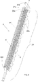
- the heat exchanger (2) comprises a coil condenser (20) comprising a plurality of parallel rectilinear tubes (20a), each of them having a longitudinal axis (X), and a plurality of "U"-shaped coupling tubes (20b), each of them connecting two consecutive rectilinear tubes (20a).
- the coupling tubes (20b) are advantageously made of plastics, rubber, iron or steel.
- each coupling tube (20b) is advantageously connected to two consecutive rectilinear tubes (20a) of the coil condenser (20) in fit-in coupling mode.
- the coupling between the coupling tubes (20b) and the rectilinear tubes (20a) of the coil condenser (20) can be obtained by means of welding if the coupling tubes (20b) are made of iron or steel.
- the volume of said coil condenser (20) is advantageously comprised between 150 cc and 200 cc.
- Each rectilinear tube (20a) of the coil condenser (20) has a diameter comprised between 9 cm and 10 cm, being preferably equal to 9.5 cm, and the center distance between two consecutive rectilinear tubes (20a) of the coil condenser (20) is comprised between 14 cm and 16 cm, being preferably equal to 15 cm.
- such a coil condenser (20) is provided with a plurality of fins (21) in spaced parallel position, each of them having a longitudinal axis (Y) orthogonal to the longitudinal axis (X) of each one of the rectilinear tubes (20a) of the coil condenser (20).
- Each fin (21) comprises holes (21a) for the passage of the rectilinear tubes (20a) of the coil condenser (20).
- Said fins (21) are configured in such a way to favor a heat exchange between the air-steam mixture contained in the circulation duct (3) and the heat transfer fluid contained in the heat exchanger (2).
- the provision of said fins (21) significantly increases the heat exchange surface between the air-steam mixture contained in the circulation duct (3) and the heat transfer fluid contained in the heat exchanger (2). Moreover, because of the special configuration of the heat exchanger (2), the air-steam mixture that flows in the circulation duct (3) hits the fins (21) of the heat exchanger, consequently slowing down the flow of said air-steam mixture in the circulation duct (3), and inevitably cooling the air-steam mixture.
- the coil condenser (20) comprises at least one inlet mouth (200) for the passage of the heat transfer fluid fed in the coil condenser (20), and at least one outlet mouth (210) for the outflow of the heat transfer fluid contained in the coil condenser (20).
- the inlet mouth (200) of the coil condenser is suitable for being connected to the water mains in order to feed cooling water in the coil condenser.
- the outlet mouth (210) of the coil condenser is advantageously connected to a tank (4) disposed in contact with one of the lateral panels (12) of the machine (1) and suitable for containing the heated water that flows out of the coil condenser (20) in such a way that said heated water can be used in the following washing cycles.
- Said heated water requires less energy to be heated to the temperature that are set for the prewashing, washing or rinsing of the dishes, thus increasing the efficiency of the machine (1) and reducing consumption.
- An electrically-controlled normally-closed valve is disposed in the outlet mouth (210) of the coil condenser (20). Said valve advantageously consists in a thermoactuator.
- the heat transfer fluid is fed and stored in the coil condenser (20) in order to be either partially or completely changed when its temperature is proximal to the dew point temperature of the air-steam mixture.
- the temperature of the heat transfer fluid contained in the coil condenser (20) must be always lower than the dew point temperature of the air-steam mixture.
- the machine (1) comprises means configured in such a way to change the heat transfer fluid contained in the coil condenser (20) several times during a drying cycle.
- said means advantageously comprise:
- the temperature sensor can be disposed in the circulation duct (3) to detect the temperature of the air-steam mixture contained in the circulation duct (3).
- the control and processing unit connected to the temperature sensor is configured in such a way to open the valve disposed in the outlet mouth (210) of the coil condenser (20) at a set frequency according to the temperature value of the air-steam mixture contained in the circulation duct (3) detected by the temperature sensor.
- said means configured in such a way to change the heat transfer fluid contained in the heat exchanger (2) several times during a drying cycle, may comprise a timer, or a printed circuit board, connected to the processing and control unit, in such a way that the valve disposed in the outlet mouth (210) of the coil condenser (20) is opened at set time intervals.
- machine (1) of the invention can be also provided with:
- Said method provides for a drying cycle that comprises the following steps:
- the air-steam mixture conveyed in the circulation duct (3) through the first opening (30) travels along the circulation duct (3) grazing the surface of the coil condenser (20) that contains the heat transfer fluid. Consequently, the air-steam mixture is cooled, partially condensing the steam, and the cooled air-steam mixture is introduced from the circulation duct (3) into the wash chamber (10) where it is mixed with the air-steam mixture.
- the machine (1) of the invention permits to progressively and gradually reduce the humidity contained in the air-steam mixture, in such a way that said mixture is partially dehumidified when it is reintroduced into the wash chamber (10), and is capable of absorbing a new quantity of steam, gradually removing the humidity contained in the wash chamber (10) or deposited on the dishes contained therein.
- the process for the drying of dishes with the machine (1) also provides for a changing cycle of the heat transfer fluid contained in the coil condenser (20).
- the changing cycle of the heat transfer fluid is repeated several times during the drying cycle with very short time intervals, each of them with duration of few tens of seconds.
- the machine (1) of the invention provides for short cooling steps, either partially or completely changing the heat transfer fluid contained in the coil condenser (20) on a periodical basis by introducing new cold water, in such a way to obtain the most linear and gradual temperature reduction possible. This avoids the abrupt cooling of the wash chamber (10) that would negatively affect the drying process, for example creating condensation on the dishes.
- the changing cycle of the heat transfer fluid contained in the coil condenser (20) provides for different steps according to the fact that said means, configured in such a way to change the heat transfer fluid contained in the heat exchanger (2) several times during a drying cycle, comprise:
- the changing cycle of the heat transfer fluid contained in the coil condenser (20) provides for the following steps:
- the changing cycle of the heat transfer fluid contained in the coil condenser (20) provides for the following steps:
- the changing cycle of the heat transfer fluid contained in the coil condenser (20) provides for the following steps:
- the changing cycle of the heat transfer fluid contained in the coil condenser (20) provides for sequentially performing, in sequential order:
- the cooling water contained in the coil condenser (20) is the remaining water from the preceding drying cycle, having achieved a temperature of approximately 36°C because it was heated through the walls of the wash chamber (10) by the washing and rinsing process before the drying cycle.
- drying cycle continues with several cooling steps of the water contained in the coil condenser (20), cyclically changing the cooling water contained in the coil condenser (20).
- the changing frequency of the cooling water contained in the coil condenser (20) is reduced.
- the temperature of the wash chamber (10) and, consequently, the heat to be removed from the air-steam mixture have decreased significantly.
- the machine (1) of the invention is not provided with means specifically intended to heat the air-steam mixture.
- the temperature of the last rinse determines the heat that generates the evaporation of the water deposited on the dishes; moreover, because of the cooling of the air-steam mixture, the flow is continuously enriched with steam, being reintroduced in the wash chamber (10) and passing on the dishes.
- the machine (1) of the invention optimizes the drying process by increasing its efficiency also at last rinse temperatures that are much lower than the temperatures measured in the machines of the prior art, i.e. at temperatures of approximately 48-54°C vs. the temperatures measured in the machines of the prior art of approximately 58-60°C, thus contributing to energy saving.
- the machine (1) of the invention significantly reduces the duration of the drying process compared to the time required by the traditional drying machines, which range from 70 to 90 minutes.
- Said water is heated until it has achieved the point (61), which can be identified as one of the upper peaks of said curve 6, wherein the temperature of said cooling water is proximal to the dew point temperature of the air-steam mixture.
- the processing and control unit enables the introduction of new cold water in the coil condenser (20).
- the temperature of the cooling water returns to a new minimum point (60).
- the highest number of changes of the cooling water contained in the coil condenser (20) is concentrated in the second step of the drying process, which can be identified with said section ⁇ t2 of the curves shown in Figs. 5, 6 and 7 .
- Such a higher number of changes of the cooling water contained in the coil condenser (20) is due to the fact that the quantity of cooling water stored in the coil condenser (20) is very limited, ranging, for example, from 100 cl to 600 cl according to the type of machine, in such a way to remove moderate amounts of heat from the air-steam mixture, avoiding the sudden cooling of the wash chamber (10).
- the machine (1) of the invention in fact, performs a dehumidification process through a number of cooling steps of the air-steam mixture characterized by sequential removals of limited amounts of heat.
- Such cooling is implemented by dividing the mass of the cooling water that is necessary to condensate the desired steam, in successive filling/emptying cycles of the coil condenser (20).
- the water consumption for the drying (or dehumidification) process is significantly reduced and the sudden cooling of the wash chamber (10) is prevented.
- the changing steps of the cooling water contained in the coil condenser (20) allow for:
- the machine (1) of the invention provides for treating the air-steam mixture inside the circulation duct (3) of the machine, preventing any dispersion or emission of steam or humidity outside the machine (1).
- the flow of air-steam mixture passing through the circulation duct (3) can be changed.
- the rotational speed of the extraction means (300) can be changed in order to extract a higher or lower quantity of air-steam mixture, or the first opening (30) of the circulation duct can be provided with suitable opening and closing means.
- the dimensions and the geometry of the circulation duct (3) can be studied and defined in such a way to guide the air-steam mixture towards the heat exchanger (2) in such a way to improve the heat exchange and optimize the drying process.
Landscapes
- Washing And Drying Of Tableware (AREA)
Description
- The present patent application for industrial invention relates to a machine for the drying of dishes or the like, and to a method for the drying of dishes or the like with said machine.
- Therefore the invention falls in the field of dishwashers, in particular in the household sector or the like.
- Obviously, nothing prevents from extending the application of the machine of the invention also to sectors other than the household one, such as for example the industrial sector, the catering sector or, generally speaking, all applications that require the washing of dishes, pots, kitchen tools or the like, or the washing and drying of garments, such as for example washer-driers.
- As it is known, the dishwashers that can be currently found on the market comprise a wash chamber suitable for housing the dishes to be washed, and for containing an air-steam mixture.
- Moreover, said dishwashers are provided with drying devices for drying the dishes at the end of the washing cycle. Said drying devices generally use water from the water mains as cooling liquid of the air-steam mixture.
- In particular, some dishwashers comprise a condensing wall disposed in the wash chamber and configured in such a way to condensate the humidity and reduce the steam title of the air-steam mixture contained in the wash chamber.
- However, the drawback of said condensing walls is that the temperature of the air-steam mixture that circulates in the wash chamber is decreased. In fact, part of the air-steam mixture contained in the wash chamber of the dishwasher grazes the condensing wall, inevitably and suddenly cooling the mixture and consequently reducing the drying power.
- As a matter of fact, the air-steam mixture is drier, but colder; such a condition impairs the drying of the dishes and may cause the condensation of the steam in the wash chamber, with consequent water dripping on the dishes.
- Other types of dishwashers are provided with a system of nozzles suitable for spraying cold water to cool an internal wall of the wash chamber, which acts as condensing wall.
- However, such a nozzle system must be fed with a constant flow of cooling water, thus causing high water consumption.
- Furthermore, dishwashers are known, which are provided with a high-capacity tank suitable for being filled with cooling water with a single operation.
- Said water is used to cool the air-steam mixture, but the dehumidification of said mixture progressively tends to become less effective because the water stored in the tank is heated, reaching the dew point temperature of the air-steam mixture and therefore losing its condensation capacity.
-
EP0978250 discloses a device for drying the dishes provided in a dishwasher with a washing tank suitable for housing the dishes to be washed, and for containing an air-steam mixture. - Such a device comprises a condensing duct in fluid communication with the washing tank of the dishwasher through a first opening for introducing the air-steam mixture from the washing tank into the condensing duct, and through a second opening for introducing the air-steam mixture from the condensing duct into the washing tank.
- Such a device also comprises a tank suitable for being filled with cold water. Such a tank is provided with a heat exchange wall with bellows-like surface disposed in the condensing duct, in such way that the cold water contained in the tank cools the air-steam mixture that passes through the condensing duct, partially condensing the humidity of said mixture.
-
EP1284627 discloses a device for the drying of crockery provided in a dishwasher with a wash tank suitable for housing the crockery to be washed, and for containing an air-steam mixture. Such a device is provided outside the wash tank and comprises a heat exchanger. In particular, the heat exchanger comprises a water conduit and an air conduit in adjacent position. - The water conduit is in fluid communication with the water mains, in such a way that the water conduit is fed with cold water.
- The air conduit, instead, is in fluid communication with the wash chamber of the dishwasher through a first opening for introducing the air-steam mixture from the wash chamber into the air conduit, and through a second opening for introducing the air-steam mixture from the air conduit into the wash chamber. The air conduit is adjacent to the water conduit in such a way that the cold water contained in the water conduit cools the air-steam mixture that passes through the air conduit, partially condensing the humidity of said mixture.
-
- Finally,
EP 2687143 discloses a machine for the drying of dishes according to the preamble ofclaim 1. - The main purpose of the present invention is to remedy the drawbacks of the prior art by disclosing a machine for the drying of dishes that is capable of dehumidifying the air-steam mixture contained in the wash chamber with low water consumption.
- Another purpose of the present invention is to disclose a machine for the drying of dishes that is capable of recovering and reusing the cooling water in the following washing cycles.
- Another purpose of the present invention is to disclose a machine for the drying of dishes that is capable of guaranteeing a balanced, progressive dehumidification of the air-steam mixture contained in the wash chamber, avoiding a sudden temperature decrease that may impair the drying process.
- These purposes are achieved according to the invention with the characteristics of the
independent claim 1. - Advantageous embodiments of the invention appear from the dependent claims.
- The machine of the invention is used for the drying of dishes and the like, and comprises:
- a box-type chassis;
- a wash chamber defined by said box-type chassis, suitable for housing said dishes and for containing an air-steam mixture;
- a circulation duct in fluid communication with the wash chamber through a first opening for introducing the air-steam mixture from the wash chamber into the circulation duct, and through a second opening for introducing the air-steam mixture from the circulation duct into the wash chamber;
- extraction means disposed in the wash chamber for extracting the air-steam mixture from the wash chamber and conveying said air-steam mixture into the circulation duct through the first opening;
- a heat exchanger disposed in the circulation duct and suitable for containing a heat transfer fluid with a lower temperature than the dew point temperature of the air-steam mixture, in such a way to cool the air-steam mixture and partially condensate the humidity of said air-steam mixture.
- The peculiarity of the machine according to the invention consists in the fact that the heat exchanger comprises a coil condenser provided with a plurality of fins designed in such a way to favor a heat exchange between the air-steam mixture contained in the circulation duct and the heat transfer fluid contained in the heat exchanger.
- Moreover, the machine of the invention comprises suitable means for changing the heat transfer fluid contained in the heat exchanger several times during a drying cycle, in such a way to determine a progressive dehumidification of the air-steam mixture in a rapid, effective way.
- The advantages of the machine according to the invention are evident, wherein the provision of a coil condenser provided with a plurality of fins significantly increases the heat exchange surface between the air-steam mixture contained in the circulation duct and the heat transfer fluid contained in the heat exchanger. Moreover, because of the special configuration of the heat exchanger of the machine according to the present invention, the air-steam mixture that flows in the circulation duct hits the fins of the heat exchanger, consequently slowing down the flow of said air-steam mixture in the circulation duct, and inevitably cooling the air-steam mixture.
- Additional features of the invention will appear clearer from the detailed description below, which refers to merely illustrative, not limiting embodiments, wherein:
-
Fig. 1 is a perspective view of the machine according to the invention; -
Fig. 2 is the same asFig. 1 , except for it shows the machine of the invention from a different angle; -
Fig. 3 is a partially interrupted side view of the machine ofFig. 1 ; -
Fig. 4 is a perspective view of a heat exchanger of the machine according to the invention; -
Fig. 5 is a chart that shows the temperature curve in the wash chamber and the temperature curve of the heat transfer fluid of the heat exchanger during the operation of the machine ofFig. 1 ; -
Fig. 6 is a chart that shows the temperature curve in the wash chamber and the temperature curve at the outlet of the circulation duct during the operation of the machine ofFig. 1 ;Fig. 7 is a chart wherein the temperature curves shown inFigs. 5 and 6 are superimposed; -
Fig. 8 is a sectional view of the heat exchanger ofFig. 4 , taken along the section plane VIII-VIII ofFig. 4 . - With reference to the attached figures, the machine according to the present invention is disclosed, which is generally indicated with reference numeral (1).
- In the following description, all dimensional or spatial terms (such as "lower", "upper", "internal", "external", "front", "back", "vertical", "horizontal" and the like) refer to the position according to which the parts of the machine (1) are represented in the attached figures.
- Moreover, it must be noted that the term "dishes" refers to all items that are suitable for being used on a table or in the kitchen, such as, for example, crockery, plates, kitchen tools, pans, pots and the like.
- With special reference to
Figs. 1 and 2 , the machine (1) is used for the drying of dishes and comprises a box-type chassis (T) that supports a plurality of covering panels (11, 12, 13, 14), of which a front panel (not shown in the attached figures), a back panel (14), an upper panel (11), a bottom panel (13) and a pair of lateral panels (12). - Said covering panels (11, 12, 13, 14) define a wash chamber (10) suitable for housing the dishes to be washed and for containing an air-steam mixture.
- The machine (1) also comprises a circulation duct (3) defined by a lateral wall (32). The circulation duct (3) in is fluid communication with the wash chamber (10) through a first opening (30) for introducing the air-steam mixture from the wash chamber into the circulation duct (3), and through a second opening (31) for introducing the air-steam mixture from the circulation duct (3) into the wash chamber.
- The first opening (30) is advantageously obtained on the upper panel (11) of the machine, whereas the second opening (31) is advantageously obtained in lower position on one of the two lateral panels (12) of the machine. In any case, the first opening (30) and the second opening (31) can be obtained in any panel (11, 12, 13, 14) of the machine.
- It must be noted that the circulation duct (3) can have more than one first opening (30) and more than one second opening (31) and that the lateral wall (32) that defines said circulation duct (3) can be obtained in one piece with one or more panels (11, 12, 13, 14) of the machine.
- With reference to
Fig. 1 , the machine (1) of the invention comprises extraction means (300) disposed in the wash chamber (10) for extracting the air-steam mixture from the wash chamber (10) and conveying said air-steam mixture in the circulation duct (3) through the first opening (30). - Said extraction means (300) comprise a fan that is advantageously installed in the proximity of the first opening (30) of the circulation duct or in the proximity of the second opening (31) of the circulation duct. Alternatively, said extraction means (300) may comprise two fans, the first one being disposed in the first opening (30) of the circulation duct, and the second one being disposed in the second opening (31) of the circulation duct.
- A heat exchanger (2) is disposed in the circulation duct (3) and is suitable for containing a heat transfer fluid with a lower temperature than the dew point temperature of the air-steam mixture, in such a way to cool the air-steam mixture and partially condensate the humidity of said air-steam mixture. Advantageously, said heat transfer fluid consists in mains water with a temperature of approximately 15°C - 20 °C.
- With reference to
Figs. 4 and8 , the heat exchanger (2) comprises a coil condenser (20) comprising a plurality of parallel rectilinear tubes (20a), each of them having a longitudinal axis (X), and a plurality of "U"-shaped coupling tubes (20b), each of them connecting two consecutive rectilinear tubes (20a). - The coupling tubes (20b) are advantageously made of plastics, rubber, iron or steel.
- Moreover, each coupling tube (20b) is advantageously connected to two consecutive rectilinear tubes (20a) of the coil condenser (20) in fit-in coupling mode. Alternatively, the coupling between the coupling tubes (20b) and the rectilinear tubes (20a) of the coil condenser (20) can be obtained by means of welding if the coupling tubes (20b) are made of iron or steel.
- The volume of said coil condenser (20) is advantageously comprised between 150 cc and 200 cc.
- Each rectilinear tube (20a) of the coil condenser (20) has a diameter comprised between 9 cm and 10 cm, being preferably equal to 9.5 cm, and the center distance between two consecutive rectilinear tubes (20a) of the coil condenser (20) is comprised between 14 cm and 16 cm, being preferably equal to 15 cm.
- Moreover, such a coil condenser (20) is provided with a plurality of fins (21) in spaced parallel position, each of them having a longitudinal axis (Y) orthogonal to the longitudinal axis (X) of each one of the rectilinear tubes (20a) of the coil condenser (20). Each fin (21) comprises holes (21a) for the passage of the rectilinear tubes (20a) of the coil condenser (20).
- Said fins (21) are configured in such a way to favor a heat exchange between the air-steam mixture contained in the circulation duct (3) and the heat transfer fluid contained in the heat exchanger (2).
- In particular, the provision of said fins (21) significantly increases the heat exchange surface between the air-steam mixture contained in the circulation duct (3) and the heat transfer fluid contained in the heat exchanger (2). Moreover, because of the special configuration of the heat exchanger (2), the air-steam mixture that flows in the circulation duct (3) hits the fins (21) of the heat exchanger, consequently slowing down the flow of said air-steam mixture in the circulation duct (3), and inevitably cooling the air-steam mixture.
- The coil condenser (20) comprises at least one inlet mouth (200) for the passage of the heat transfer fluid fed in the coil condenser (20), and at least one outlet mouth (210) for the outflow of the heat transfer fluid contained in the coil condenser (20).
- Advantageously, the inlet mouth (200) of the coil condenser is suitable for being connected to the water mains in order to feed cooling water in the coil condenser.
- The outlet mouth (210) of the coil condenser is advantageously connected to a tank (4) disposed in contact with one of the lateral panels (12) of the machine (1) and suitable for containing the heated water that flows out of the coil condenser (20) in such a way that said heated water can be used in the following washing cycles.
- Said heated water requires less energy to be heated to the temperature that are set for the prewashing, washing or rinsing of the dishes, thus increasing the efficiency of the machine (1) and reducing consumption.
- An electrically-controlled normally-closed valve is disposed in the outlet mouth (210) of the coil condenser (20). Said valve advantageously consists in a thermoactuator.
- The heat transfer fluid is fed and stored in the coil condenser (20) in order to be either partially or completely changed when its temperature is proximal to the dew point temperature of the air-steam mixture. In fact, the temperature of the heat transfer fluid contained in the coil condenser (20) must be always lower than the dew point temperature of the air-steam mixture.
- More precisely, the machine (1) comprises means configured in such a way to change the heat transfer fluid contained in the coil condenser (20) several times during a drying cycle.
- In particular, said means advantageously comprise:
- a temperature sensor disposed in the coil condenser (20) to detect the temperature of the heat transfer fluid contained in the coil condenser (20);
- a comparator connected to the temperature sensor and configured in such a way to compare the temperature of the heat transfer fluid contained in the coil condenser (20) detected by the temperature sensor with a set value that is lower than the dew point temperature of the air-steam mixture;
- a control and processing unit connected to the comparator in such a way to open the valve disposed in the outlet mouth (210) of the coil condenser (20) and either partially or completely change the heat transfer fluid contained in the coil condenser (20) before the temperature of the heat transfer fluid of the coil condenser (20) detected by the temperature sensor has achieved said set value.
- It must be noted that, alternatively, the temperature sensor can be disposed in the circulation duct (3) to detect the temperature of the air-steam mixture contained in the circulation duct (3). In such a case, the control and processing unit connected to the temperature sensor is configured in such a way to open the valve disposed in the outlet mouth (210) of the coil condenser (20) at a set frequency according to the temperature value of the air-steam mixture contained in the circulation duct (3) detected by the temperature sensor.
- As an alternative to the aforesaid temperature sensor, said means, configured in such a way to change the heat transfer fluid contained in the heat exchanger (2) several times during a drying cycle, may comprise a timer, or a printed circuit board, connected to the processing and control unit, in such a way that the valve disposed in the outlet mouth (210) of the coil condenser (20) is opened at set time intervals.
- It must be noted that the machine (1) of the invention can be also provided with:
- sensors disposed in the circulation duct (3) to measure the humidity of the air-steam mixture contained in the circulation duct (3), detecting the temperature of the air-steam mixture that comes in and/or out of the circulation duct (3);
- flow meters disposed in the circulation duct (3) to detect the flow rate of the air-steam mixture passing through the circulation duct (3);
- temperature sensors disposed in the wash chamber (10) of the machine to measure the internal temperature of the wash chamber (10);
- temperature sensors disposed in the inlet mouth (200) of the coil condenser (20) to measure the temperature of the cooling water taken from the water mains.
- The description continues with reference to the method for the drying of dishes with the machine (1) of the invention.
- Said method provides for a drying cycle that comprises the following steps:
- introducing the heat transfer fluid into the coil condenser (20); said heat transfer fluid having a lower temperature than the dew point temperature of the air-steam mixture contained in the wash chamber (10) of the machine (1);
- actuating the extraction means (300) disposed in the wash chamber (10) to extract the air-steam mixture from the wash chamber (10) and convey said air-steam mixture in the circulation duct (3) through the first opening (30);
- introducing the cooled air-steam mixture from the circulation duct (3) into the wash chamber (10) through the second opening (31).
- In particular, the air-steam mixture conveyed in the circulation duct (3) through the first opening (30) travels along the circulation duct (3) grazing the surface of the coil condenser (20) that contains the heat transfer fluid. Consequently, the air-steam mixture is cooled, partially condensing the steam, and the cooled air-steam mixture is introduced from the circulation duct (3) into the wash chamber (10) where it is mixed with the air-steam mixture.
- Such a movement of the air-steam mixture makes the mixture contained in the wash chamber (10) drier and drier, i.e. with a progressively reduced content of steam, thus favoring the drying of the dishes.
- Therefore, the machine (1) of the invention permits to progressively and gradually reduce the humidity contained in the air-steam mixture, in such a way that said mixture is partially dehumidified when it is reintroduced into the wash chamber (10), and is capable of absorbing a new quantity of steam, gradually removing the humidity contained in the wash chamber (10) or deposited on the dishes contained therein.
- The process for the drying of dishes with the machine (1) also provides for a changing cycle of the heat transfer fluid contained in the coil condenser (20).
- In particular, the changing cycle of the heat transfer fluid is repeated several times during the drying cycle with very short time intervals, each of them with duration of few tens of seconds.
- More precisely, the machine (1) of the invention provides for short cooling steps, either partially or completely changing the heat transfer fluid contained in the coil condenser (20) on a periodical basis by introducing new cold water, in such a way to obtain the most linear and gradual temperature reduction possible. This avoids the abrupt cooling of the wash chamber (10) that would negatively affect the drying process, for example creating condensation on the dishes.
- The changing cycle of the heat transfer fluid contained in the coil condenser (20) provides for different steps according to the fact that said means, configured in such a way to change the heat transfer fluid contained in the heat exchanger (2) several times during a drying cycle, comprise:
- a temperature sensor disposed in the coil condenser (20);
- a temperature sensor disposed in the circulation duct (3);
- a timer.
- In particular, if said means comprise a temperature sensor disposed in the coil condenser (20) to measure the temperature of the heat transfer fluid contained therein, the changing cycle of the heat transfer fluid contained in the coil condenser (20) provides for the following steps:
- measuring the temperature of the heat transfer fluid contained in the coil condenser (20);
- comparing the temperature of the heat transfer fluid contained in the coil condenser (20) detected by the temperature sensor with a set value that is lower than the dew point temperature of the air-steam mixture;
- opening the valve disposed in the outlet mouth (210) of the coil condenser (20) and either partially or completely changing the heat transfer fluid contained in the coil condenser (20) before the temperature of the heat transfer fluid detected by the temperature sensor has achieved the set value.
- If the temperature sensor is disposed in the circulation duct (3) to measure the temperature of the air-steam mixture contained in the circulation duct (3), the changing cycle of the heat transfer fluid contained in the coil condenser (20) provides for the following steps:
- measuring the temperature of the air-steam mixture contained in the circulation duct (3);
- opening the valve disposed in the outlet mouth (210) of the coil condenser (20) and either partially or completely changing the heat transfer fluid contained in the coil condenser (20) at a set frequency according to the temperature value of the air-steam mixture contained in the circulation duct (3) detected by the temperature sensor.
- Instead, if said means, configured in such a way to change the heat transfer fluid contained in the heat exchanger (2) several times during a drying cycle, comprise a timer, the changing cycle of the heat transfer fluid contained in the coil condenser (20) provides for the following steps:
- actuating the timer;
- opening the valve disposed in the outlet mouth (210) of the coil condenser (20) and either partially or completely changing the heat transfer fluid at set time intervals.
- In particular, in the latter case, the changing cycle of the heat transfer fluid contained in the coil condenser (20) provides for sequentially performing, in sequential order:
- a number of changes comprised between 11 and 13 of the heat transfer fluid contained in the coil condenser (20) at time intervals with duration comprised between 30 and 50 seconds, preferably 40 seconds;
- a number of changes comprised between 3 and 5 of the heat transfer fluid contained in the coil condenser (20) at time intervals with duration comprised between 160 and 200 seconds, preferably 180 seconds.
- With reference to the charts of
Figs. 5, 6 and 7 , it must be noted that: -
numeral reference 5 designates the temperature curve in the wash chamber (10), said curve being indicated with a dotted line; - numeral reference 6 designates the temperature curve of the cooling fluid contained with the coil condenser (20), said curve being indicated with a continuous line;
-
numeral reference 7 designates the temperature curve of the air-steam mixture at the outlet of the circulation duct (3), said curve being indicated with a broken line. - It must be noted that said curves are experimental, being obtained from laboratory tests, and that, for illustrative not limiting purposes, they refer to an internal volume of the wash chamber (10) of 185 liters.
- In particular, said curves were determined on the basis of the following parameters:
- air flow (or air-steam mixture) through the circulation duct (3) equal to 270 I/min;
- temperature of the wash chamber (10) at the start of the drying process equal to 55°C (temperature determined from the preceding washing and rinsing cycles);
- quantity of cooling water stored in the coil condenser (20) equal to approximately 200 cl.
- During the first seconds of the drying cycle, which can be identified with the section Δt1 of said curves, the following steps are provided:
- actuating the extraction means (300), in such a way to convey the air-steam mixture from the wash chamber (10) into the circulation duct (3);
- reintroducing the air-steam mixture from the circulation duct (3) into the wash chamber (10), consequently absorbing the heat of the dishes accumulated during the washing and rinsing step.
- It must be noted that, during the first seconds of the drying cycle, the cooling water contained in the coil condenser (20) is the remaining water from the preceding drying cycle, having achieved a temperature of approximately 36°C because it was heated through the walls of the wash chamber (10) by the washing and rinsing process before the drying cycle.
- In the section Δt1 of the drying cycle, therefore, the temperature of the air-steam mixture and the temperature of the cooling water contained in the coil condenser (20) increase, exceeding the temperature of the wash chamber (10), which is an average temperature detected at approximately half of the height of said wash chamber (10).
- This is due to the fact that, being heated by the preceding washing and rinsing process, the water contained in the coil condenser (20) removes a low amount of heat from the air-steam mixture. Moreover, while returning in the wash chamber (10), the air-steam mixture absorbs the heat of the dishes, being additionally heated.
- Now, the drying cycle continues with several cooling steps of the water contained in the coil condenser (20), cyclically changing the cooling water contained in the coil condenser (20).
- During said second step of the drying cycle, which can be identified with the section Δt2 of the curves shown in
Figs. 5, 6 and 7 , the process provides for: - periodically changing the cooling water contained in the coil condenser (20);
- cooling the air-steam mixture that recirculates between the circulation duct (3) and the wash chamber (10);
- progressively and gradually cooling the wash chamber (10).
- During the third step of the drying cycle, which can be identified with the section Δt3 of the curves shown in
Figs. 5, 6 and 7 , the changing frequency of the cooling water contained in the coil condenser (20) is reduced. In fact, because of the frequent cooling steps of the water contained in the coil condenser (20), the temperature of the wash chamber (10) and, consequently, the heat to be removed from the air-steam mixture have decreased significantly. - During the last step of the drying cycle, which can be identified with the section Δt4 of the curves shown in
Figs. 5, 6 and 7 : - the changes of the cooling water contained in the coil condenser (20) are interrupted;
- the cooling water that is lastly introduced into the coil condenser (20) absorbs the heat of the hot water contained in the tank (4), reaching a higher temperature than the average temperature of the wash chamber (10);
- the air-steam mixture continues on recirculating between the circulation duct (3) and the wash chamber (10), but the temperature of the air-steam mixture remains lower than the temperature of the wash chamber (10);
- because of the hot water contained in the tank (4), the lateral panel (12) of the machine according to the invention is a hot wall and tends to regulate the temperature in the wash chamber (10) for the rest of the drying cycle, preventing internal condensation and generating a stable flow of hot air on the dishes.
- Therefore, the machine (1) of the invention is not provided with means specifically intended to heat the air-steam mixture.
- The temperature of the last rinse determines the heat that generates the evaporation of the water deposited on the dishes; moreover, because of the cooling of the air-steam mixture, the flow is continuously enriched with steam, being reintroduced in the wash chamber (10) and passing on the dishes.
- The machine (1) of the invention optimizes the drying process by increasing its efficiency also at last rinse temperatures that are much lower than the temperatures measured in the machines of the prior art, i.e. at temperatures of approximately 48-54°C vs. the temperatures measured in the machines of the prior art of approximately 58-60°C, thus contributing to energy saving.
- Moreover, the machine (1) of the invention significantly reduces the duration of the drying process compared to the time required by the traditional drying machines, which range from 70 to 90 minutes.
- In fact, as shown in
Figs. 5, 6 and 7 , it can be noted that the entire drying process lasts approximately 30-40 minutes (the value is correlated to the aforementioned parameters). - With reference to the
curve 5 ofFigs. 5, 6 and 7 , it can be noted that the temperature of the wash chamber (10) is gradually reduced over time, without any sudden variation. - The curve 6 of
Figs. 5, 6 and 7 clearly shows the cooling steps and the periodical change of the cooling water contained in the coil condenser (20). - In particular, the point (60), which can be identified as one of the lower peaks of said curve 6, designated the introduction in the coil condenser (20) of cold water from the water mains.
- Said water is heated until it has achieved the point (61), which can be identified as one of the upper peaks of said curve 6, wherein the temperature of said cooling water is proximal to the dew point temperature of the air-steam mixture.
- In the point (61), the processing and control unit enables the introduction of new cold water in the coil condenser (20). In view of the above, the temperature of the cooling water returns to a new minimum point (60).
- Moreover, it can be noted that the highest number of changes of the cooling water contained in the coil condenser (20) is concentrated in the second step of the drying process, which can be identified with said section Δt2 of the curves shown in
Figs. 5, 6 and 7 . Such a higher number of changes of the cooling water contained in the coil condenser (20) is due to the fact that the quantity of cooling water stored in the coil condenser (20) is very limited, ranging, for example, from 100 cl to 600 cl according to the type of machine, in such a way to remove moderate amounts of heat from the air-steam mixture, avoiding the sudden cooling of the wash chamber (10). - The machine (1) of the invention, in fact, performs a dehumidification process through a number of cooling steps of the air-steam mixture characterized by sequential removals of limited amounts of heat.
- Such cooling is implemented by dividing the mass of the cooling water that is necessary to condensate the desired steam, in successive filling/emptying cycles of the coil condenser (20). In view of the above, the water consumption for the drying (or dehumidification) process is significantly reduced and the sudden cooling of the wash chamber (10) is prevented.
- In particular, the changing steps of the cooling water contained in the coil condenser (20) allow for:
- producing a progressive dehumidification of the air-steam mixture that recirculates between the circulation duct (3) and the wash chamber (10);
- reducing the temperature of the air-steam mixture at the outlet of the circulation duct (3), in such a way to avoid condensation inside the wash chamber (10) and water dripping on the dishes disposed in said wash chamber.
- The machine (1) of the invention provides for treating the air-steam mixture inside the circulation duct (3) of the machine, preventing any dispersion or emission of steam or humidity outside the machine (1).
- Equivalent variations and modifications can be made to the present embodiments of the invention, which are within the reach of an expert of the field, falling in any case within the scope of the invention.
- For example, the flow of air-steam mixture passing through the circulation duct (3) can be changed.
- Moreover, the rotational speed of the extraction means (300) can be changed in order to extract a higher or lower quantity of air-steam mixture, or the first opening (30) of the circulation duct can be provided with suitable opening and closing means.
- Furthermore, also the dimensions and the geometry of the circulation duct (3) can be studied and defined in such a way to guide the air-steam mixture towards the heat exchanger (2) in such a way to improve the heat exchange and optimize the drying process.
Claims (8)
- Machine (1) for the drying of dishes or the like, comprising:- a box-type chassis (T);- awash chamber (10) defined by said box-type chassis (T), suitable for housing said dishes and for containing an air-steam mixture;- a circulation duct (3) in fluid communication with the wash chamber (10) through a first opening (30) for introducing the air-steam mixture from the wash chamber into the circulation duct (3), and through a second opening (31) for introducing the air-steam mixture from the circulation duct (3) into the wash chamber;- extraction means (300) disposed on the box-type chassis (T) for extracting the air-steam mixture from the wash chamber (10) and conveying said air-steam mixture in the circulation duct (3) through the first opening (30);- a heat exchanger (2) disposed in the circulation duct (3) and suitable for containing a heat transfer fluid with a lower temperature than the dew point temperature of the air-steam mixture, in such a way to cool the air-steam mixture and partially condensate the humidity of said air-steam mixture;said heat exchanger (2) comprises a coil condenser (20) designed in such a way to favor a heat exchange between the air-steam mixture contained in the circulation duct (3) and the heat transfer fluid contained in the heat exchanger (2);
said machine (1) also comprising means configured in such a way to change the heat transfer fluid contained in the heat exchanger (2)
during a drying cycle,
said means, configured in such a way to change the heat transfer fluid contained in the heat exchanger (2) during a drying cycle, comprise:- a timer;- an electrically-controlled normally-closed valve;- a control and processing unit connected to the timer in such a way to open said valve and either partially or completely change the heat transfer fluid contained in the coil condenser (20) at set time intervals, several times during a drying cycle,characterized in that
the coil condenser (20) of the heat exchanger (2) is provided with a plurality of fins (21);
said electrically-controlled normally-closed valve is disposed in an outlet mouth (B) of the coil condenser (20);
the control and processing unit and the timer are configured in such a way to define during the drying cycle:- a first time interval (Δt1), wherein the valve is closed in such a way that the heat transfer fluid remains in the coil condenser (20);- a second time interval (Δt2), wherein the valve is open several times to allow the exiting of the heat transfer fluid from the coil condenser (20);- a third time interval (At3), wherein the exiting frequency of the heat transfer fluid contained in the coil condenser (20) is reduced; and- a fourth time interval (Δt4), wherein the exiting of the heat transfer fluid contained in the coil condenser (20) is interrupted. - The machine (1) of claim 1, wherein said coil condenser (20) comprises:- a plurality of rectilinear tubes (20a) in parallel position, each of them with longitudinal axis (X);- a plurality of "U"-shaped coupling tubes (20b), each of them connecting two consecutive rectilinear tubes (20a).
- The machine (1) of claim 2, wherein said fins (21) are parallel, each fin (21) having a longitudinal axis (Y) orthogonal to the longitudinal axis (X) of each of the rectilinear tubes (20a) of the coil condenser (20);
each fin (21) comprising holes (21a) for the passage of the rectilinear tubes (20a) of the coil condenser (20). - The machine (1) of claim 2 or 3, wherein each coupling tube (20b) is connected to two consecutive rectilinear tubes (20a) of the coil condenser (20) by means of fit-in coupling or welding.
- The machine (1) of any one of claims 2 to 4, wherein each rectilinear tube (20a) of the coil condenser (20) has a diameter comprised between 9 cm and 10 cm and the center distance between two consecutive rectilinear tubes (20a) of the coil condenser (20) is comprised between 14 cm and 16 cm.
- The machine (1) of any one of the preceding claims, wherein the volume of said coil condenser (20) is comprised between 150 cc and 200 cc.
- Method for the drying of dishes or the like with a machine (1) according to any one of the preceding claims, comprising:a) a drying cycle comprising the following steps:- introducing the heat transfer fluid into the coil condenser (20); the temperature of said heat transfer fluid being lower than the dew point temperature of the air-steam mixture contained in the wash chamber (10) of the machine (1);- actuating the extraction means (300) disposed in the wash chamber (10) for extracting the air-steam mixture from the wash chamber (10) and conveying said air-steam mixture into the circulation duct (3) through the first opening (30);- introducing the cooled air-steam mixture from the circulation duct (3) into the wash chamber (10) through the second opening (31);b) a changing cycle of the heat transfer fluid contained in the coil condenser (20); said changing cycle of the heat transfer fluid being repeated several times during the drying cycle,
wherein the changing cycle of the heat transfer fluid contained in the coil condenser (20) comprises the following steps:- actuating the timer in such a way that the timer sends signals to the control and processing unit to control the opening of the valve;- maintaining the valve closed in the first time interval (Δt1) in such a way that the heat transfer fluid remain in the coil condenser (20) and the heat transfer fluid temperature increases;- opening of the valve several times to allow a partial or total exiting of the heat transfer fluid from the coil condenser (20) in the second time interval (Δt2);- reducing of a changing frequency of the heat transfer fluid contained in the coil condenser (20) in the third time interval (Δt3);- interrupting of the change of the heat transfer fluid contained in the coil condenser (20) in the fourth time interval (Δt4). - The method of claim 7, wherein said changing cycle of the heat transfer fluid provides for performing the following steps in sequential order:- a number of changes comprised between 11 and 13 of the heat transfer fluid contained in the coil condenser (20) at time intervals comprised between 30 and 50 seconds;- a number of changes comprised between 3 and 5 of the heat transfer fluid contained in the coil condenser (20) at time intervals comprised between 160 and 200 seconds.
Applications Claiming Priority (2)
| Application Number | Priority Date | Filing Date | Title |
|---|---|---|---|
| IT201600123848 | 2016-12-06 | ||
| PCT/EP2017/081572 WO2018104333A1 (en) | 2016-12-06 | 2017-12-05 | Machine for the drying of dishes or the like and method for the drying of dishes or the like with said machine. |
Publications (3)
| Publication Number | Publication Date |
|---|---|
| EP3551027A1 EP3551027A1 (en) | 2019-10-16 |
| EP3551027B1 true EP3551027B1 (en) | 2021-03-24 |
| EP3551027B8 EP3551027B8 (en) | 2021-04-28 |
Family
ID=58402066
Family Applications (1)
| Application Number | Title | Priority Date | Filing Date |
|---|---|---|---|
| EP17811544.0A Not-in-force EP3551027B8 (en) | 2016-12-06 | 2017-12-05 | Machine for the drying of dishes or the like and method for the drying of dishes or the like with said machine. |
Country Status (3)
| Country | Link |
|---|---|
| EP (1) | EP3551027B8 (en) |
| CN (1) | CN110072426B (en) |
| WO (1) | WO2018104333A1 (en) |
Families Citing this family (6)
| Publication number | Priority date | Publication date | Assignee | Title |
|---|---|---|---|---|
| CN108577767B (en) * | 2018-06-21 | 2023-08-29 | 佛山市顺德区美的洗涤电器制造有限公司 | Drying device for dish-washing machine and dish-washing machine |
| CN109700412B (en) * | 2019-02-12 | 2021-02-02 | 佛山市顺德区美的洗涤电器制造有限公司 | Water tank type dish washing machine and drying system and drying method thereof |
| CN109700411B (en) * | 2019-02-12 | 2021-02-02 | 佛山市顺德区美的洗涤电器制造有限公司 | Condensing equipment of basin formula dish washer and have its basin formula dish washer |
| CN110495844A (en) * | 2019-09-09 | 2019-11-26 | 火星人厨具股份有限公司 | Dishwasher condensation drying system |
| WO2024110026A1 (en) * | 2022-11-23 | 2024-05-30 | Electrolux Appliances Aktiebolag | Dishwasher with heat pump |
| CN120769719A (en) * | 2023-02-28 | 2025-10-10 | 埃科莱布美国股份有限公司 | Dishwashers with energy recovery systems |
Family Cites Families (25)
| Publication number | Priority date | Publication date | Assignee | Title |
|---|---|---|---|---|
| US3908681A (en) * | 1973-11-09 | 1975-09-30 | Gen Electric | Forced air circulation system for a dishwasher |
| JP2975836B2 (en) * | 1994-02-17 | 1999-11-10 | 三洋電機株式会社 | Dryers and washers |
| JPH10117991A (en) * | 1996-10-16 | 1998-05-12 | Osaka Gas Co Ltd | Dish drier |
| SE511231C2 (en) * | 1997-11-10 | 1999-08-30 | Aake Larsson | Method of drying goods and apparatus for carrying out the process |
| IT1303213B1 (en) | 1998-08-06 | 2000-11-02 | Bitron Spa | DISHWASHER DRYING DEVICE AT THE END OF THE DISHWASHER WASHING PROCESS |
| DE10023346A1 (en) * | 2000-05-12 | 2001-11-15 | Diehl Ako Stiftung Gmbh & Co | Dishwasher crockery dryer has heat exchanger surface on which washing chamber air condenses; condensate passes to temporary store connected to water carrying, washing chambers |
| ES2284990T3 (en) * | 2003-02-11 | 2007-11-16 | Whirlpool Corporation | DISHWASHER WITH DRYING SYSTEM. |
| CN1611181A (en) * | 2003-10-30 | 2005-05-04 | 乐金电子(天津)电器有限公司 | Condensing and drying device for dish-washing machine |
| US20080210279A1 (en) * | 2007-01-30 | 2008-09-04 | Hildenbrand Karl | Shroud-Type Dishwashing Machine With Condensation Precipitation Device |
| DE102007007133A1 (en) * | 2007-02-13 | 2008-08-14 | Meiko Maschinenbau Gmbh & Co. Kg | Front-loading dishwasher with heat recovery |
| JP5023782B2 (en) * | 2007-04-16 | 2012-09-12 | パナソニック株式会社 | Dishwasher |
| DE102007059516A1 (en) * | 2007-12-11 | 2009-06-18 | BSH Bosch und Siemens Hausgeräte GmbH | Method for drying time control in dishwashers |
| DE602008006078D1 (en) * | 2008-09-25 | 2011-05-19 | Bonferraro Spa | Hood dishwasher with heat recovery device |
| KR20100113730A (en) * | 2009-04-14 | 2010-10-22 | 엘지전자 주식회사 | Dish washer |
| EP2241663B1 (en) * | 2009-04-15 | 2013-03-20 | Electrolux Home Products Corporation N.V. | Washing-drying machine and method for operating the same |
| DE102009029149A1 (en) * | 2009-09-02 | 2011-03-03 | BSH Bosch und Siemens Hausgeräte GmbH | Dishwasher and associated control method |
| DE102010034715A1 (en) * | 2010-08-18 | 2012-02-23 | Etimex Technical Components Gmbh | Method and device for drying moist air |
| ITVI20120025A1 (en) * | 2012-01-27 | 2013-07-28 | Dihr Ali S P A | PROFESSIONAL ERGONOMIC DISHWASHER |
| ITTO20120641A1 (en) * | 2012-07-20 | 2014-01-21 | Indesit Co Spa | HOUSEHOLD WASHING AND / OR DRYING MACHINE |
| EP2749682B1 (en) * | 2012-12-27 | 2015-08-05 | Electrolux Home Products Corporation N.V. | Washing-dryer machine |
| US9635997B2 (en) * | 2013-02-12 | 2017-05-02 | Lg Electronics Inc. | Dishwasher and method of controlling the same |
| AU2013392438A1 (en) * | 2013-06-11 | 2015-12-24 | Electrolux Appliances Aktiebolag | Washing machine |
| KR102094340B1 (en) * | 2014-03-17 | 2020-03-30 | 삼성전자주식회사 | Household appliance having drying apparatus |
| US20160029869A1 (en) * | 2015-08-06 | 2016-02-04 | David R. McKinney | Dishwasher with vacuum drying and method |
| CN105520704A (en) * | 2016-01-19 | 2016-04-27 | 佛山市顺德区美的洗涤电器制造有限公司 | Drying device for dish washing machine and dish washing machine provided with drying device |
-
2017
- 2017-12-05 EP EP17811544.0A patent/EP3551027B8/en not_active Not-in-force
- 2017-12-05 CN CN201780075373.7A patent/CN110072426B/en not_active Expired - Fee Related
- 2017-12-05 WO PCT/EP2017/081572 patent/WO2018104333A1/en not_active Ceased
Non-Patent Citations (1)
| Title |
|---|
| None * |
Also Published As
| Publication number | Publication date |
|---|---|
| EP3551027A1 (en) | 2019-10-16 |
| CN110072426B (en) | 2022-10-14 |
| WO2018104333A1 (en) | 2018-06-14 |
| CN110072426A (en) | 2019-07-30 |
| EP3551027B8 (en) | 2021-04-28 |
Similar Documents
| Publication | Publication Date | Title |
|---|---|---|
| EP3551027B1 (en) | Machine for the drying of dishes or the like and method for the drying of dishes or the like with said machine. | |
| CN107149452B (en) | Dish washer with drying system | |
| EP3082555B1 (en) | Dishwasher comprising heat pump system | |
| KR102094340B1 (en) | Household appliance having drying apparatus | |
| EP3082554B1 (en) | Dishwasher comprising heat pump system | |
| EP3129541B1 (en) | Washing and drying machine | |
| EP2691567B1 (en) | Clothes treating apparatus having heat exchanger cleaning device | |
| US20130180553A1 (en) | Dishwasher | |
| US20170196431A1 (en) | Heating circulation type drying module of dishwasher | |
| CN102368943A (en) | A dishwasher, a door assembly for the dishwasher, and an associated method for drying dishware | |
| KR102658397B1 (en) | Dishwasher with heat pump | |
| CN111150359A (en) | Dish washing machine with inner container drying system | |
| KR20200064269A (en) | Dishwasher with heat pump | |
| US20250113975A1 (en) | Dishwasher | |
| KR20150030532A (en) | Dish Washer | |
| KR102511843B1 (en) | Dish Washer | |
| EP3524127B1 (en) | Dishwasher | |
| EP1656877A2 (en) | Dishwasher | |
| KR20130070278A (en) | dish washer | |
| JP5837410B2 (en) | Dishwasher | |
| US12290226B2 (en) | Dishwashing appliance having an air-drying dehumidification assembly | |
| WO2017088934A1 (en) | Dishwasher and method for drying washed items in a dishwasher | |
| CN107130398A (en) | For the dehumidifier of washing machine and the washing machine with it | |
| CN119488260A (en) | Condensing device for dishwasher and dishwasher | |
| KR20150106700A (en) | Dishwasher |
Legal Events
| Date | Code | Title | Description |
|---|---|---|---|
| STAA | Information on the status of an ep patent application or granted ep patent |
Free format text: STATUS: UNKNOWN |
|
| STAA | Information on the status of an ep patent application or granted ep patent |
Free format text: STATUS: THE INTERNATIONAL PUBLICATION HAS BEEN MADE |
|
| PUAI | Public reference made under article 153(3) epc to a published international application that has entered the european phase |
Free format text: ORIGINAL CODE: 0009012 |
|
| STAA | Information on the status of an ep patent application or granted ep patent |
Free format text: STATUS: REQUEST FOR EXAMINATION WAS MADE |
|
| 17P | Request for examination filed |
Effective date: 20190701 |
|
| AK | Designated contracting states |
Kind code of ref document: A1 Designated state(s): AL AT BE BG CH CY CZ DE DK EE ES FI FR GB GR HR HU IE IS IT LI LT LU LV MC MK MT NL NO PL PT RO RS SE SI SK SM TR |
|
| AX | Request for extension of the european patent |
Extension state: BA ME |
|
| DAV | Request for validation of the european patent (deleted) | ||
| DAX | Request for extension of the european patent (deleted) | ||
| GRAP | Despatch of communication of intention to grant a patent |
Free format text: ORIGINAL CODE: EPIDOSNIGR1 |
|
| STAA | Information on the status of an ep patent application or granted ep patent |
Free format text: STATUS: GRANT OF PATENT IS INTENDED |
|
| INTG | Intention to grant announced |
Effective date: 20200806 |
|
| GRAS | Grant fee paid |
Free format text: ORIGINAL CODE: EPIDOSNIGR3 |
|
| GRAA | (expected) grant |
Free format text: ORIGINAL CODE: 0009210 |
|
| STAA | Information on the status of an ep patent application or granted ep patent |
Free format text: STATUS: THE PATENT HAS BEEN GRANTED |
|
| REG | Reference to a national code |
Ref country code: DE Ref legal event code: R081 Ref document number: 602017035378 Country of ref document: DE Owner name: INDELFAB S.P.A. IN LIQUIDAZIONE, FABRIANO, IT Free format text: FORMER OWNER: J.P. INDUSTRIES S.P.A., FABRIANO, IT |
|
| AK | Designated contracting states |
Kind code of ref document: B1 Designated state(s): AL AT BE BG CH CY CZ DE DK EE ES FI FR GB GR HR HU IE IS IT LI LT LU LV MC MK MT NL NO PL PT RO RS SE SI SK SM TR |
|
| REG | Reference to a national code |
Ref country code: GB Ref legal event code: FG4D |
|
| REG | Reference to a national code |
Ref country code: CH Ref legal event code: PK Free format text: BERICHTIGUNG B8 Ref country code: CH Ref legal event code: EP |
|
| RAP4 | Party data changed (patent owner data changed or rights of a patent transferred) |
Owner name: INDELFAB S.P.A. IN LIQUIDAZIONE |
|
| REG | Reference to a national code |
Ref country code: IE Ref legal event code: FG4D |
|
| REG | Reference to a national code |
Ref country code: AT Ref legal event code: REF Ref document number: 1373618 Country of ref document: AT Kind code of ref document: T Effective date: 20210415 Ref country code: DE Ref legal event code: R096 Ref document number: 602017035378 Country of ref document: DE |
|
| REG | Reference to a national code |
Ref country code: LT Ref legal event code: MG9D |
|
| PG25 | Lapsed in a contracting state [announced via postgrant information from national office to epo] |
Ref country code: NO Free format text: LAPSE BECAUSE OF FAILURE TO SUBMIT A TRANSLATION OF THE DESCRIPTION OR TO PAY THE FEE WITHIN THE PRESCRIBED TIME-LIMIT Effective date: 20210624 Ref country code: GR Free format text: LAPSE BECAUSE OF FAILURE TO SUBMIT A TRANSLATION OF THE DESCRIPTION OR TO PAY THE FEE WITHIN THE PRESCRIBED TIME-LIMIT Effective date: 20210625 Ref country code: FI Free format text: LAPSE BECAUSE OF FAILURE TO SUBMIT A TRANSLATION OF THE DESCRIPTION OR TO PAY THE FEE WITHIN THE PRESCRIBED TIME-LIMIT Effective date: 20210324 Ref country code: HR Free format text: LAPSE BECAUSE OF FAILURE TO SUBMIT A TRANSLATION OF THE DESCRIPTION OR TO PAY THE FEE WITHIN THE PRESCRIBED TIME-LIMIT Effective date: 20210324 Ref country code: BG Free format text: LAPSE BECAUSE OF FAILURE TO SUBMIT A TRANSLATION OF THE DESCRIPTION OR TO PAY THE FEE WITHIN THE PRESCRIBED TIME-LIMIT Effective date: 20210624 |
|
| PG25 | Lapsed in a contracting state [announced via postgrant information from national office to epo] |
Ref country code: SE Free format text: LAPSE BECAUSE OF FAILURE TO SUBMIT A TRANSLATION OF THE DESCRIPTION OR TO PAY THE FEE WITHIN THE PRESCRIBED TIME-LIMIT Effective date: 20210324 Ref country code: RS Free format text: LAPSE BECAUSE OF FAILURE TO SUBMIT A TRANSLATION OF THE DESCRIPTION OR TO PAY THE FEE WITHIN THE PRESCRIBED TIME-LIMIT Effective date: 20210324 Ref country code: LV Free format text: LAPSE BECAUSE OF FAILURE TO SUBMIT A TRANSLATION OF THE DESCRIPTION OR TO PAY THE FEE WITHIN THE PRESCRIBED TIME-LIMIT Effective date: 20210324 |
|
| REG | Reference to a national code |
Ref country code: NL Ref legal event code: MP Effective date: 20210324 |
|
| REG | Reference to a national code |
Ref country code: AT Ref legal event code: MK05 Ref document number: 1373618 Country of ref document: AT Kind code of ref document: T Effective date: 20210324 |
|
| PG25 | Lapsed in a contracting state [announced via postgrant information from national office to epo] |
Ref country code: NL Free format text: LAPSE BECAUSE OF FAILURE TO SUBMIT A TRANSLATION OF THE DESCRIPTION OR TO PAY THE FEE WITHIN THE PRESCRIBED TIME-LIMIT Effective date: 20210324 |
|
| PG25 | Lapsed in a contracting state [announced via postgrant information from national office to epo] |
Ref country code: SM Free format text: LAPSE BECAUSE OF FAILURE TO SUBMIT A TRANSLATION OF THE DESCRIPTION OR TO PAY THE FEE WITHIN THE PRESCRIBED TIME-LIMIT Effective date: 20210324 Ref country code: AT Free format text: LAPSE BECAUSE OF FAILURE TO SUBMIT A TRANSLATION OF THE DESCRIPTION OR TO PAY THE FEE WITHIN THE PRESCRIBED TIME-LIMIT Effective date: 20210324 Ref country code: CZ Free format text: LAPSE BECAUSE OF FAILURE TO SUBMIT A TRANSLATION OF THE DESCRIPTION OR TO PAY THE FEE WITHIN THE PRESCRIBED TIME-LIMIT Effective date: 20210324 Ref country code: EE Free format text: LAPSE BECAUSE OF FAILURE TO SUBMIT A TRANSLATION OF THE DESCRIPTION OR TO PAY THE FEE WITHIN THE PRESCRIBED TIME-LIMIT Effective date: 20210324 Ref country code: LT Free format text: LAPSE BECAUSE OF FAILURE TO SUBMIT A TRANSLATION OF THE DESCRIPTION OR TO PAY THE FEE WITHIN THE PRESCRIBED TIME-LIMIT Effective date: 20210324 |
|
| PG25 | Lapsed in a contracting state [announced via postgrant information from national office to epo] |
Ref country code: IS Free format text: LAPSE BECAUSE OF FAILURE TO SUBMIT A TRANSLATION OF THE DESCRIPTION OR TO PAY THE FEE WITHIN THE PRESCRIBED TIME-LIMIT Effective date: 20210724 Ref country code: PT Free format text: LAPSE BECAUSE OF FAILURE TO SUBMIT A TRANSLATION OF THE DESCRIPTION OR TO PAY THE FEE WITHIN THE PRESCRIBED TIME-LIMIT Effective date: 20210726 Ref country code: PL Free format text: LAPSE BECAUSE OF FAILURE TO SUBMIT A TRANSLATION OF THE DESCRIPTION OR TO PAY THE FEE WITHIN THE PRESCRIBED TIME-LIMIT Effective date: 20210324 Ref country code: RO Free format text: LAPSE BECAUSE OF FAILURE TO SUBMIT A TRANSLATION OF THE DESCRIPTION OR TO PAY THE FEE WITHIN THE PRESCRIBED TIME-LIMIT Effective date: 20210324 Ref country code: SK Free format text: LAPSE BECAUSE OF FAILURE TO SUBMIT A TRANSLATION OF THE DESCRIPTION OR TO PAY THE FEE WITHIN THE PRESCRIBED TIME-LIMIT Effective date: 20210324 |
|
| REG | Reference to a national code |
Ref country code: DE Ref legal event code: R097 Ref document number: 602017035378 Country of ref document: DE |
|
| PG25 | Lapsed in a contracting state [announced via postgrant information from national office to epo] |
Ref country code: ES Free format text: LAPSE BECAUSE OF FAILURE TO SUBMIT A TRANSLATION OF THE DESCRIPTION OR TO PAY THE FEE WITHIN THE PRESCRIBED TIME-LIMIT Effective date: 20210324 Ref country code: AL Free format text: LAPSE BECAUSE OF FAILURE TO SUBMIT A TRANSLATION OF THE DESCRIPTION OR TO PAY THE FEE WITHIN THE PRESCRIBED TIME-LIMIT Effective date: 20210324 Ref country code: DK Free format text: LAPSE BECAUSE OF FAILURE TO SUBMIT A TRANSLATION OF THE DESCRIPTION OR TO PAY THE FEE WITHIN THE PRESCRIBED TIME-LIMIT Effective date: 20210324 |
|
| PLBE | No opposition filed within time limit |
Free format text: ORIGINAL CODE: 0009261 |
|
| STAA | Information on the status of an ep patent application or granted ep patent |
Free format text: STATUS: NO OPPOSITION FILED WITHIN TIME LIMIT |
|
| PG25 | Lapsed in a contracting state [announced via postgrant information from national office to epo] |
Ref country code: SI Free format text: LAPSE BECAUSE OF FAILURE TO SUBMIT A TRANSLATION OF THE DESCRIPTION OR TO PAY THE FEE WITHIN THE PRESCRIBED TIME-LIMIT Effective date: 20210324 |
|
| 26N | No opposition filed |
Effective date: 20220104 |
|
| PGFP | Annual fee paid to national office [announced via postgrant information from national office to epo] |
Ref country code: LU Payment date: 20220126 Year of fee payment: 5 |
|
| PGFP | Annual fee paid to national office [announced via postgrant information from national office to epo] |
Ref country code: GB Payment date: 20220126 Year of fee payment: 5 Ref country code: DE Payment date: 20220127 Year of fee payment: 5 Ref country code: CH Payment date: 20220128 Year of fee payment: 5 Ref country code: IE Payment date: 20220127 Year of fee payment: 5 |
|
| PG25 | Lapsed in a contracting state [announced via postgrant information from national office to epo] |
Ref country code: IS Free format text: LAPSE BECAUSE OF FAILURE TO SUBMIT A TRANSLATION OF THE DESCRIPTION OR TO PAY THE FEE WITHIN THE PRESCRIBED TIME-LIMIT Effective date: 20210724 |
|
| PGFP | Annual fee paid to national office [announced via postgrant information from national office to epo] |
Ref country code: MT Payment date: 20220128 Year of fee payment: 5 Ref country code: MC Payment date: 20220130 Year of fee payment: 5 Ref country code: FR Payment date: 20220126 Year of fee payment: 5 Ref country code: BE Payment date: 20220126 Year of fee payment: 5 |
|
| PG25 | Lapsed in a contracting state [announced via postgrant information from national office to epo] |
Ref country code: IT Free format text: LAPSE BECAUSE OF FAILURE TO SUBMIT A TRANSLATION OF THE DESCRIPTION OR TO PAY THE FEE WITHIN THE PRESCRIBED TIME-LIMIT Effective date: 20210324 |
|
| PG25 | Lapsed in a contracting state [announced via postgrant information from national office to epo] |
Ref country code: CY Free format text: LAPSE BECAUSE OF FAILURE TO SUBMIT A TRANSLATION OF THE DESCRIPTION OR TO PAY THE FEE WITHIN THE PRESCRIBED TIME-LIMIT Effective date: 20210324 |
|
| REG | Reference to a national code |
Ref country code: DE Ref legal event code: R119 Ref document number: 602017035378 Country of ref document: DE |
|
| PG25 | Lapsed in a contracting state [announced via postgrant information from national office to epo] |
Ref country code: HU Free format text: LAPSE BECAUSE OF FAILURE TO SUBMIT A TRANSLATION OF THE DESCRIPTION OR TO PAY THE FEE WITHIN THE PRESCRIBED TIME-LIMIT; INVALID AB INITIO Effective date: 20171205 |
|
| REG | Reference to a national code |
Ref country code: CH Ref legal event code: PL |
|
| GBPC | Gb: european patent ceased through non-payment of renewal fee |
Effective date: 20221205 |
|
| REG | Reference to a national code |
Ref country code: BE Ref legal event code: MM Effective date: 20221231 |
|
| PG25 | Lapsed in a contracting state [announced via postgrant information from national office to epo] |
Ref country code: LU Free format text: LAPSE BECAUSE OF NON-PAYMENT OF DUE FEES Effective date: 20221205 |
|
| PG25 | Lapsed in a contracting state [announced via postgrant information from national office to epo] |
Ref country code: LI Free format text: LAPSE BECAUSE OF NON-PAYMENT OF DUE FEES Effective date: 20221231 Ref country code: IE Free format text: LAPSE BECAUSE OF NON-PAYMENT OF DUE FEES Effective date: 20221205 Ref country code: GB Free format text: LAPSE BECAUSE OF NON-PAYMENT OF DUE FEES Effective date: 20221205 Ref country code: DE Free format text: LAPSE BECAUSE OF NON-PAYMENT OF DUE FEES Effective date: 20230701 Ref country code: CH Free format text: LAPSE BECAUSE OF NON-PAYMENT OF DUE FEES Effective date: 20221231 |
|
| PG25 | Lapsed in a contracting state [announced via postgrant information from national office to epo] |
Ref country code: FR Free format text: LAPSE BECAUSE OF NON-PAYMENT OF DUE FEES Effective date: 20221231 Ref country code: BE Free format text: LAPSE BECAUSE OF NON-PAYMENT OF DUE FEES Effective date: 20221231 |
|
| PG25 | Lapsed in a contracting state [announced via postgrant information from national office to epo] |
Ref country code: MK Free format text: LAPSE BECAUSE OF FAILURE TO SUBMIT A TRANSLATION OF THE DESCRIPTION OR TO PAY THE FEE WITHIN THE PRESCRIBED TIME-LIMIT Effective date: 20210324 |
|
| PG25 | Lapsed in a contracting state [announced via postgrant information from national office to epo] |
Ref country code: MC Free format text: LAPSE BECAUSE OF NON-PAYMENT OF DUE FEES Effective date: 20230103 |
|
| PG25 | Lapsed in a contracting state [announced via postgrant information from national office to epo] |
Ref country code: MC Free format text: LAPSE BECAUSE OF NON-PAYMENT OF DUE FEES Effective date: 20230103 |
|
| PG25 | Lapsed in a contracting state [announced via postgrant information from national office to epo] |
Ref country code: MT Free format text: LAPSE BECAUSE OF FAILURE TO SUBMIT A TRANSLATION OF THE DESCRIPTION OR TO PAY THE FEE WITHIN THE PRESCRIBED TIME-LIMIT Effective date: 20210324 |
|
| PG25 | Lapsed in a contracting state [announced via postgrant information from national office to epo] |
Ref country code: TR Free format text: LAPSE BECAUSE OF FAILURE TO SUBMIT A TRANSLATION OF THE DESCRIPTION OR TO PAY THE FEE WITHIN THE PRESCRIBED TIME-LIMIT Effective date: 20210324 |