EP3550178B1 - Engrenage externe de dispositif d'engrenage à ondes - Google Patents
Engrenage externe de dispositif d'engrenage à ondes Download PDFInfo
- Publication number
- EP3550178B1 EP3550178B1 EP16923084.4A EP16923084A EP3550178B1 EP 3550178 B1 EP3550178 B1 EP 3550178B1 EP 16923084 A EP16923084 A EP 16923084A EP 3550178 B1 EP3550178 B1 EP 3550178B1
- Authority
- EP
- European Patent Office
- Prior art keywords
- thickness
- barrel
- diaphragm
- circumferential end
- toothed gear
- Prior art date
- Legal status (The legal status is an assumption and is not a legal conclusion. Google has not performed a legal analysis and makes no representation as to the accuracy of the status listed.)
- Active
Links
- 230000015572 biosynthetic process Effects 0.000 claims description 9
- 230000007423 decrease Effects 0.000 claims description 6
- 150000001875 compounds Chemical class 0.000 description 7
- 238000012360 testing method Methods 0.000 description 3
- 230000000694 effects Effects 0.000 description 2
- 238000005452 bending Methods 0.000 description 1
- 230000001419 dependent effect Effects 0.000 description 1
- 238000011161 development Methods 0.000 description 1
- 230000018109 developmental process Effects 0.000 description 1
- 238000010586 diagram Methods 0.000 description 1
- 230000002708 enhancing effect Effects 0.000 description 1
Images


Classifications
-
- F—MECHANICAL ENGINEERING; LIGHTING; HEATING; WEAPONS; BLASTING
- F16—ENGINEERING ELEMENTS AND UNITS; GENERAL MEASURES FOR PRODUCING AND MAINTAINING EFFECTIVE FUNCTIONING OF MACHINES OR INSTALLATIONS; THERMAL INSULATION IN GENERAL
- F16H—GEARING
- F16H49/00—Other gearings
- F16H49/001—Wave gearings, e.g. harmonic drive transmissions
-
- F—MECHANICAL ENGINEERING; LIGHTING; HEATING; WEAPONS; BLASTING
- F16—ENGINEERING ELEMENTS AND UNITS; GENERAL MEASURES FOR PRODUCING AND MAINTAINING EFFECTIVE FUNCTIONING OF MACHINES OR INSTALLATIONS; THERMAL INSULATION IN GENERAL
- F16H—GEARING
- F16H1/00—Toothed gearings for conveying rotary motion
- F16H1/28—Toothed gearings for conveying rotary motion with gears having orbital motion
- F16H1/32—Toothed gearings for conveying rotary motion with gears having orbital motion in which the central axis of the gearing lies inside the periphery of an orbital gear
-
- F—MECHANICAL ENGINEERING; LIGHTING; HEATING; WEAPONS; BLASTING
- F16—ENGINEERING ELEMENTS AND UNITS; GENERAL MEASURES FOR PRODUCING AND MAINTAINING EFFECTIVE FUNCTIONING OF MACHINES OR INSTALLATIONS; THERMAL INSULATION IN GENERAL
- F16H—GEARING
- F16H49/00—Other gearings
- F16H49/001—Wave gearings, e.g. harmonic drive transmissions
- F16H2049/003—Features of the flexsplines therefor
Definitions
- the present invention relates to a silk-hat-type strain wave gearing equipped with a silk-hat-shaped flexible externally toothed gear. More specifically, the present invention relates to an externally toothed gear configured to be used for a strain wave gearing, having enhanced fatigue strength in an operating state in which a high-load torque is applied.
- An externally toothed gear for a silk-hat-type strain wave gearing is provided with a cylindrical barrel, a diaphragm which is continuous with one end of the barrel and spreads radially outward, and an annular thick-walled boss which is continuous with an outer circumferential end of the diaphragm.
- External teeth are integrally formed in an outer circumferential portion of an opening end on a distal-end side of the barrel.
- an outside diameter of the strain wave gearing is increased relative to a cup-type strain wave gearing equipped with a cup-shaped externally toothed gear.
- the outside diameter of the diaphragm may be reduced in order to reduce the outside diameter of the strain wave gearing.
- the diaphragm is repeatedly subjected to a large bending stress due to deformation of the barrel, which is repeatedly flexed in the radial direction by a wave generator.
- Patent Document 1 discloses a silk-hat-type strain wave gearing, wherein stress concentration occurring in a diaphragm of an externally toothed gear that is flexed by a wave generator is mitigated and strength of the diaphragm is increased.
- a thickness of the diaphragm is made greater in an inner circumferential end and an outer circumferential end than in a middle part therebetween, and stress concentration in the diaphragm is mitigated.
- Patent Document 2 discloses an improvement of the invention disclosed in Patent Document 1.
- a thickness of a diaphragm part of an externally toothed gear is at maximum at an inner circumferential end thereof, and is at minimum in a middle part between the inner circumferential end and an outer circumferential end. Stress concentration in the diaphragm part of the externally toothed gear is thereby even further mitigated, and a stress state of the diaphragm can be made uniform.
- Patent Document 3 discloses using a streamline to prescribe a cross-sectional shape of a base portion for attachment of the diaphragm to a boss.
- Patent Document 4 discloses an externally toothed gear having the features of the preamble of claim 1.
- the diaphragm shape of a silk-hat-shaped externally toothed gear was designed through use of a stress analysis that considered ellipsoidal flexural deformation by a wave generator, an applied load torque, and mounting error of the externally toothed gear.
- a stress analysis that considered ellipsoidal flexural deformation by a wave generator, an applied load torque, and mounting error of the externally toothed gear.
- endurance testing of an externally toothed gear was performed with a further increased current load. It was assumed from current stress analysis that a diaphragm would not experience fatigue fracture even under the aforementioned increased load, but fatigue fracture was confirmed in results of endurance testing of a diaphragm.
- the inventors investigated the cause of diaphragm breakage on the basis of stress analysis and the like, and considered the effect of a thrust force occurring in the externally toothed gear due to load torque in the stress analysis. As a result, the inventors confirmed that a phenomenon of diaphragm breakage observed in an actual endurance test of an externally toothed gear in a state of high load torque can be reproduced in stress analysis as well.
- the inventors focused on the thrust force caused by the load torque, which had not conventionally been considered in designing the diaphragm shape of an externally toothed gear. On this basis, the inventors designed a diaphragm shape while taking into account the effect of the thrust force. The inventors discovered that by taking the thrust force caused by the load torque into account, breakage of the diaphragm can be suppressed even in a state of high load torque, and durability of the externally toothed gear can be increased.
- An object of the present invention is to provide an externally toothed gear configured to be used for a strain wave gearing, provided with a diaphragm shape whereby, on the basis of the above new knowledge, fatigue strength of the diaphragm at high load torque can be enhanced.
- the thickness of the diaphragm is made greater in the inner circumferential end and outer circumferential end than in the middle part in the diaphragm body portion, and the thickness of the inner circumferential end is greater than that of the outer circumferential end.
- the thickness of the barrel-side end part in the curved portion of the diaphragm is also greater than that of the middle part, which has the smallest thickness of the diaphragm body portion, and the thickness of the barrel-side end part is less than that of the outer circumferential end of the diaphragm body portion.
- each portion of the diaphragm By setting the thickness of each portion of the diaphragm in this manner, stress can be smoothly distributed along the diaphragm from the inner circumferential end to the outer circumferential end thereof. In particular, concentration of stress that occurs in the diaphragm due to a thrust force from the load torque can be mitigated, and the maximum stress can be reduced. As a result, it is possible to prevent or suppress breakage of the diaphragm in an operating state of high load torque, and durability of the externally toothed gear can be increased.
- the thickness t(A) of the inner circumferential end of the diaphragm body portion satisfies 1.2 ⁇ t A / t B ⁇ 2.7 ; the thickness t(C) of the outer circumferential end of the diaphragm body portion satisfies 1.0 ⁇ t C / t B ⁇ 2.3 ; and the thickness t(D) of the barrel-side end part of the curved portion of the diaphragm satisfies 1.0 ⁇ t D / t B ⁇ 2.3 .
- the thickness t(D) of the barrel-side end part of the curved portion of the diaphragm is set so as to be greater than the thickness t(B) of the middle part of the diaphragm body portion.
- the thickness t(A) of the inner circumferential end of the diaphragm body portion, using the thickness t(B) of the middle part as a reference, is also set so as to be greater than in the case of the conventional externally toothed gear.
- a middle position extending from the inner circumferential end connected to the diaphragm body portion to the barrel-side end part connected to the barrel is referred to herein as a curved-portion middle position.
- the thickness of the diaphragm preferably gradually increases from the inner circumferential end to the curved-portion middle position and gradually decreases from the curved-portion middle position to the barrel-side end part, and preferably, t E > t A is satisfied, where t(E) is the thickness of the curved-portion middle position, and 1.3 ⁇ t E / t B ⁇ 2.8 is satisfied with reference to the thickness t(B) of the middle part of the diaphragm body portion.
- a thickness of a cylinder portion extending from an external tooth formation portion, in which external teeth are formed, to the barrel-side end part of the curved portion of the diaphragm can be configured so as to be constant, and to be the same as the thickness t(D) of the barrel-side end part.
- FIG. 1 is a schematic longitudinal sectional view illustrating the overall structure of the silk-hat-type strain wave gearing according to the present embodiment
- FIG. 2 is an explanatory diagram illustrating a state of meshing of teeth.
- a strain wave gearing 1 is constituted from an annular rigid internally toothed gear 2, a silk-hat-shaped flexible externally toothed gear 3 disposed coaxially therewith and on an inside thereof, and a wave generator 4 which has an ellipsoidal outline and is fitted inside the externally toothed gear 3.
- the externally toothed gear 3 is provided with a barrel 10, a diaphragm 20, and a boss 30, and is silk-hat shaped overall.
- the barrel 10 is cylindrical and capable of flexing. One end of the barrel 10 is an open end 11.
- the diaphragm 20 spreads radially outward continuously with another end of the barrel 10.
- the annular boss 30 having a rectangular cross section is formed continuously with an outer circumferential edge of the diaphragm 20.
- the boss 30 is a rigid portion for attaching the externally toothed gear 3 to another member (not illustrated).
- the wave generator 4 is constituted from a hollow hub 41, an ellipsoidal rigid cam plate 42 fitted on an outer circumference of the hollow hub 41, and a wave bearing 43 fitted on an outer circumference of the rigid cam plate 42.
- An external tooth formation portion of the flexible externally toothed gear 3 in which external teeth 5 thereof are formed is ellipsoidally flexed by the wave generator 4.
- the external teeth 5 of the externally toothed gear 3 are meshed with internal teeth 6 of the rigid internally toothed gear 2 at two locations positioned at both ends of a major axis of an ellipse.
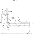
- FIG. 3 is half sectional view in which the silk-hat-shaped externally toothed gear 3 is cut by a plane that includes the center axis 1a thereof.
- the barrel 10 of the externally toothed gear 3 is provided with an external tooth formation portion 12, one end of which is the open end 11, and a cylinder portion 13 having a constant thickness, extending from the external tooth formation portion 12 to the diaphragm 20.
- the external teeth 5 are formed in a portion on an outer circumferential surface of the external tooth formation portion 12.
- the thickness of the cylinder portion 13 is constant in the present example, but the cross-sectional shape of the cylinder portion 13 can also be set so that a wall thickness thereof gradually decreases toward the external tooth formation portion 12 from a diaphragm 20 side.
- the diaphragm 20 is provided with a boss base portion 21, a diaphragm body portion 22, and a curved portion 23.
- the diaphragm body portion 22 extends in a radial direction perpendicular to the center axis 1a.
- the curved portion 23 is continuous with an inner circumferential end A of the diaphragm body portion 22, and curves toward the barrel 10 along the center axis 1a from a radially inward direction.
- a barrel-side end part D of the curved portion 23 is connected to the cylinder portion 13 of the barrel 10.
- the boss base portion 21 extends radially outward from an outer circumferential end C of the diaphragm body portion 22, and is connected to a circular inner circumferential surface 31 of the boss 30.
- an inner circumferential surface portion of the cylinder portion 13 of the barrel 10 of the externally toothed gear 3 is prescribed by an inside straight line 52 extending parallel to the center axis 1a from a region 51 connected to the external tooth formation portion 12 to the barrel-side end part D.
- An outer circumferential surface portion of the cylinder portion 13 is also prescribed by an outside straight line 53 extending parallel to the center axis 1a.
- the cylinder portion 13 having a constant thickness is prescribed by the inside straight line 52 and the outside straight line 53.
- An inner circumferential surface portion of the curved portion 23 of the diaphragm 20 connected to the cylinder portion 13 is prescribed by a recessed arc 55.
- One end of the recessed arc 55 is smoothly connected to the inside straight line 52 at the position of the barrel-side end part D.
- An outer circumferential surface portion of the curved portion 23 is prescribed by an extended-straight-line end portion of the outside straight line 53 extending past the barrel-side end part D, a convex arc 57 smoothly connected to the extended straight line portion 53a, and a straight line portion 58 which is smoothly connected to another end of the convex arc 57 and which extends radially outward.
- a middle position of the curved portion from the inner circumferential end A to the barrel-side end part D is designated as E.
- a curvature radius of the outside convex arc 57 is smaller than the curvature radius of the inside recessed arc 55.
- a wall thickness of the curved portion 23 is greatest at the curved-portion middle position E, gradually increases from the inner circumferential end A to the curved-portion middle position E, and gradually decreases from the curved-portion middle position E to the barrel-side end part D.
- a barrel-side end surface portion of the diaphragm body portion 22 connected to the curved portion 23 is prescribed by a compound recessed curve 59.
- a middle part between the inner circumferential end A and the outer circumferential end C in the diaphragm body portion 22 is designated as B.
- the compound recessed curve 59 is constituted from a recessed arc 59a prescribed from the inner circumferential end A to the middle part B, and a recessed arc 59b prescribed from the middle part B to the outer circumferential end C, for example.
- One end of the recessed arc 59a is smoothly connected to the recessed arc 55 at the position of the inner circumferential end A, and another end of the recessed arc 59a is smoothly connected to the recessed arc 59b.
- An end surface portion on an opposite side of the diaphragm body portion 22 is prescribed by a straight line 58 extending past the inner circumferential end A from an end of a straight line portion 58a.
- the straight line 58 extends to a position of the outer circumferential end C along the radial direction perpendicular to the center axis 1a.
- a thickness of the diaphragm body portion 22 prescribed by the compound recessed curve 59 and the straight line 58 is smallest in the middle part B, gradually increases from the middle part B to the inner circumferential end A, and gradually increases from the middle part B to the outer circumferential end C.
- a barrel-side end surface portion of the boss base portion 21 connected to the outer circumferential end C of the diaphragm body portion 22 is prescribed by an arc portion of the recessed arc 59b of the compound recessed curve 59 that extends past the outer circumferential end C.
- An end of the recessed arc 59b is connected to a straight line 61 that prescribes an end surface of the boss 30 on the same side thereof.
- An end surface portion on an opposite side of the boss base portion 21 is prescribed by a compound recessed curve 63 smoothly connected to an end of the straight line 58 at the position of the outer circumferential end C. Another end of the compound recessed curve 63 is smoothly connected to the circular inner circumferential surface 31 of the boss 30.
- a streamline disclosed in Patent Document 3 JP S61 173851 U ) can be used as the compound recessed curve 63.
- a thickness of the boss base portion 21 increases from the position of the outer circumferential end C to the circular inner circumferential surface 31.
- the thicknesses of the inner circumferential end A, the middle part B, the outer circumferential end C, the barrel-side end part D, and the curved-portion middle position E in the diaphragm 20 are designated as t(A), t(B), t(C), t(D), and t(E), respectively, they are set so that t E > t A > t C > t D > t B is satisfied.
- the thicknesses of the inner circumferential end A, the outer circumferential end C, the barrel-side end part D, and the curved-portion middle position E are preferably set as described below, with reference to the thickness t(B) of the middle part B, the thickness t(B) having the smallest thickness.
- the thickness t(A) of the inner circumferential end A satisfies 1.2 ⁇ t A / t B ⁇ 2.7 ; the thickness t(C) of the outer circumferential end C satisfies 1.0 ⁇ t C / t B ⁇ 2.3 ; the thickness t(D) of the barrel-side end part D satisfies 1.0 ⁇ t D / t B ⁇ 2.3 ; and the thickness t(E) of the curved-portion middle position E satisfies 1.3 ⁇ t E / t B ⁇ 2.8 .
- the thickness t(D) of the barrel-side end part D of the curved portion 23 of the diaphragm 20 is greater than the t(B) of the middle part B, which is the portion of the diaphragm 20 having the smallest thickness, as described above.
- the thickness t(A) of the inner circumferential end A of the diaphragm 20, using the thickness t(B) of the middle part of the diaphragm 20 as a reference, is set so as to be greater than in the case of the conventional silk-hat-shaped externally toothed gear.
- the thickness t(E) of the curved-portion middle position E is set so that the curved-portion middle position E is the portion of the diaphragm 20 having the greatest thickness.
Landscapes
- Engineering & Computer Science (AREA)
- General Engineering & Computer Science (AREA)
- Mechanical Engineering (AREA)
- Retarders (AREA)
Claims (6)
- Engrenage extérieurement denté (3) configuré pour être utilisé pour un train d'engrenages à onde de déformation (1), dans lequel l'engrenage extérieurement denté (3) peut être fléchi de manière ellipsoïdale par un générateur d'ondes (4) pour former un état d'engrènement partiel avec un engrenage intérieurement denté (2) rigide, l'engrenage extérieurement denté (3) comprenant :un corps cylindrique (10) prévu avec une extrémité qui est une extrémité ouverte (11) ; des dents externes (5) formées sur une partie d'une surface circonférentielle externe du corps cylindrique (10) sur un côté de son extrémité ouverte (11) ; un diaphragme (20) qui est continu avec une autre extrémité du corps cylindrique (10) et s'écarte vers l'extérieur dans une direction radiale du corps cylindrique (10) ; et un bossage annulaire (30) formé de manière continue avec une extrémité circonférentielle externe (C) du diaphragme (20),dans lequel le diaphragme (20) comprend :une partie de corps de diaphragme (22) s'étendant dans la direction radiale ;une partie incurvée (23) qui est continue avec une extrémité circonférentielle interne (A) de la partie de corps de diaphragme (22), s'incurve vers le corps cylindrique (10) le long d'un axe central (1a) à partir d'une direction vers l'intérieur dans la direction radiale, et est raccordée au corps cylindrique (10) ; etune partie de base de bossage (21) qui s'étend vers l'extérieur dans la direction radiale à partir de l'extrémité circonférentielle externe (C) de la partie de corps de diaphragme (22), et est raccordée à une surface circonférentielle interne (31) du bossage (30) ; etdans lequel une épaisseur du diaphragme (20) diminue progressivement d'une position de la partie de base de bossage (21) raccordée à la surface circonférentielle interne (31) du bossage (30) à une partie centrale (B) entre l'extrémité circonférentielle externe (C) et l'extrémité circonférentielle interne (A) dans la partie de corps de diaphragme (22) et l'épaisseur du diaphragme (20) augmente progressivement de la partie centrale (B) jusqu'à l'extrémité circonférentielle interne (A) de la partie de corps de diaphragme (22) ;caractérisé en ce que :
les épaisseurs de l'extrémité circonférentielle interne (A), de la partie centrale (B) et de l'extrémité circonférentielle externe (C) du diaphragme (20), et une épaisseur d'une partie d'extrémité (D) du côté du corps cylindrique de la partie incurvée (23) raccordée au corps cylindrique (10) satisfont :
- Engrenage extérieurement denté (3) pour un train d'engrenages à onde de déformation (1) selon la revendication 1,
dans lequel, en référence à l'épaisseur t(B) de la partie centrale (B) de la partie de corps de diaphragme (22),
l'épaisseur t(A) de l'extrémité circonférentielle interne (A) satisfait :


- Engrenage extérieurement denté (3) pour un train d'engrenages à onde de déformation (1) selon la revendication 1,
dans lequel l'épaisseur du diaphragme (20) augmente progressivement de l'extrémité circonférentielle interne (A) jusqu'à une position centrale de partie incurvée (E) entre l'extrémité circonférentielle interne (A) et la partie d'extrémité (D) du côté du corps cylindrique, et diminue progressivement de la position centrale de partie incurvée (E) jusqu'à la partie d'extrémité (D) du côté du corps cylindrique,
dans lequel une épaisseur t(E) de la position centrale de partie incurvée (E) satisfait :

- Engrenage extérieurement denté (3) pour un train d'engrenages à onde de déformation (1) selon la revendication 1,
dans lequel le corps cylindrique (10) comprend une partie de formation de dents externes (12) où les dents externes (5) sont formées, et une partie de cylindre (13) allant de la partie de formation de dents externes (12) jusqu'à la partie d'extrémité (D) du côté du corps cylindrique de la partie incurvée (23), et
une épaisseur de la partie de cylindre (13) est constante et est la même que l'épaisseur t(D) de la partie d'extrémité (D) du côté du corps cylindrique. - Engrenage extérieurement denté (3) pour un train d'engrenages à onde de déformation (1) selon la revendication 1,
dans lequel l'épaisseur du diaphragme (20) augmente progressivement de l'extrémité circonférentielle interne (A) de la partie incurvée (23) jusqu'à une position centrale de partie incurvée (E) entre l'extrémité circonférentielle interne (A) et la partie d'extrémité (D) du côté du corps cylindrique, et diminue progressivement de la position centrale de partie incurvée (E) jusqu'à la partie d'extrémité (D) du côté du corps cylindrique,
dans lequel une épaisseur t(E) de la position centrale de partie incurvée (E) satisfait :


- Train d'engrenages à onde de déformation (1) comprenant :un engrenage intérieurement denté (2) annulaire rigide ;l'engrenage extérieurement denté (3) selon l'une quelconque des revendications 1 à 5 ; etun générateur d'ondes (4) pour fléchir l'engrenage extérieurement denté (3) dans sa direction radiale pour s'engrener partiellement avec l'engrenage intérieurement denté (2) et pour déplacer les positions engrenées entre les engrenages d'une une direction circonférentielle.
Applications Claiming Priority (1)
| Application Number | Priority Date | Filing Date | Title |
|---|---|---|---|
| PCT/JP2016/085642 WO2018100701A1 (fr) | 2016-11-30 | 2016-11-30 | Engrenage externe de dispositif d'engrenage à ondes |
Publications (3)
| Publication Number | Publication Date |
|---|---|
| EP3550178A1 EP3550178A1 (fr) | 2019-10-09 |
| EP3550178A4 EP3550178A4 (fr) | 2020-04-22 |
| EP3550178B1 true EP3550178B1 (fr) | 2021-03-10 |
Family
ID=62242000
Family Applications (1)
| Application Number | Title | Priority Date | Filing Date |
|---|---|---|---|
| EP16923084.4A Active EP3550178B1 (fr) | 2016-11-30 | 2016-11-30 | Engrenage externe de dispositif d'engrenage à ondes |
Country Status (7)
| Country | Link |
|---|---|
| US (1) | US10890239B2 (fr) |
| EP (1) | EP3550178B1 (fr) |
| JP (1) | JP6656781B2 (fr) |
| KR (1) | KR102136987B1 (fr) |
| CN (1) | CN109983251B (fr) |
| TW (1) | TWI735644B (fr) |
| WO (1) | WO2018100701A1 (fr) |
Families Citing this family (6)
| Publication number | Priority date | Publication date | Assignee | Title |
|---|---|---|---|---|
| CN109139855A (zh) * | 2018-10-03 | 2019-01-04 | 凌子龙 | 双柔轮谐波减速机 |
| CN109578551B (zh) * | 2018-12-06 | 2020-08-21 | 北京工业大学 | 一种基于连续过渡曲线的谐波减速器柔轮杯体 |
| CN111255876B (zh) * | 2020-01-20 | 2021-02-09 | 珠海格力电器股份有限公司 | 一种柔性齿轮和谐波减速器 |
| JP2022092751A (ja) | 2020-12-11 | 2022-06-23 | セイコーエプソン株式会社 | 歯車装置およびロボット |
| JP2022096109A (ja) | 2020-12-17 | 2022-06-29 | セイコーエプソン株式会社 | 歯車装置およびロボット |
| JP2023076100A (ja) * | 2021-11-22 | 2023-06-01 | ニデックドライブテクノロジー株式会社 | 可撓性外歯歯車、波動減速機、およびロボット |
Family Cites Families (19)
| Publication number | Priority date | Publication date | Assignee | Title |
|---|---|---|---|---|
| JPS58506B2 (ja) | 1976-03-12 | 1983-01-06 | 三菱マテリアル株式会社 | ダイカスト用光輝耐食性 Al 合金 |
| JPS61173851A (ja) | 1985-01-29 | 1986-08-05 | Seiko Seiki Co Ltd | 内面研削方法 |
| JPS61173851U (fr) | 1985-04-19 | 1986-10-29 | ||
| JPH03118346A (ja) | 1989-09-30 | 1991-05-20 | Sekisui Chem Co Ltd | エステルの製造方法 |
| JPH03118346U (fr) * | 1990-03-16 | 1991-12-06 | ||
| JP2535503Y2 (ja) * | 1991-05-20 | 1997-05-14 | 株式会社ハーモニック・ドライブ・システムズ | カップ型歯車式調和変速装置における外歯および内歯の噛み合わせ構造 |
| JP3118346B2 (ja) | 1993-04-20 | 2000-12-18 | 大同特殊鋼株式会社 | 歯 車 |
| WO1996018833A1 (fr) * | 1994-12-14 | 1996-06-20 | Harmonic Drive Systems Inc. | Dispositif a engrenage souple du type haut-de-forme |
| JP3580506B2 (ja) | 1994-12-14 | 2004-10-27 | 株式会社ハーモニック・ドライブ・システムズ | シルクハット型撓み噛み合い式歯車装置 |
| JP3768261B2 (ja) | 1995-05-19 | 2006-04-19 | 株式会社ハーモニック・ドライブ・システムズ | 偏平型波動歯車装置 |
| JPH09273609A (ja) * | 1996-04-04 | 1997-10-21 | Harmonic Drive Syst Ind Co Ltd | シルクハット型撓み噛み合い式歯車装置 |
| WO1999018364A1 (fr) * | 1997-10-02 | 1999-04-15 | Harmonic Drive Systems Inc. | Systeme d'engrenages souples en forme de chapeau |
| JP4133018B2 (ja) * | 2002-06-21 | 2008-08-13 | 株式会社ハーモニック・ドライブ・システムズ | シルクハット型波動歯車装置の波動発生器の組み込み方法、および、当該組み込み方法に用いるシルクハット形状の可撓性外歯歯車 |
| JP2007303592A (ja) * | 2006-05-12 | 2007-11-22 | Honda Motor Co Ltd | 波動歯車装置 |
| JP5826275B2 (ja) * | 2011-08-17 | 2015-12-02 | 株式会社ハーモニック・ドライブ・システムズ | 波動歯車装置の可撓性外歯歯車 |
| CN103562593B (zh) * | 2012-05-31 | 2016-03-16 | 谐波传动系统有限公司 | 波动齿轮装置及可挠性外齿齿轮 |
| JP2015102181A (ja) * | 2013-11-26 | 2015-06-04 | キヤノン株式会社 | 波動歯車減速機 |
| JP6614988B2 (ja) * | 2016-02-08 | 2019-12-04 | 株式会社ハーモニック・ドライブ・システムズ | カップ形状の可撓性外歯歯車および波動歯車装置 |
| TWI641771B (zh) * | 2016-12-29 | 2018-11-21 | 財團法人工業技術研究院 | 諧波傳動裝置 |
-
2016
- 2016-11-30 CN CN201680090914.9A patent/CN109983251B/zh active Active
- 2016-11-30 US US16/348,884 patent/US10890239B2/en active Active
- 2016-11-30 KR KR1020197015550A patent/KR102136987B1/ko active IP Right Grant
- 2016-11-30 EP EP16923084.4A patent/EP3550178B1/fr active Active
- 2016-11-30 WO PCT/JP2016/085642 patent/WO2018100701A1/fr unknown
- 2016-11-30 JP JP2018553592A patent/JP6656781B2/ja active Active
-
2017
- 2017-09-06 TW TW106130366A patent/TWI735644B/zh active
Non-Patent Citations (1)
| Title |
|---|
| None * |
Also Published As
| Publication number | Publication date |
|---|---|
| TWI735644B (zh) | 2021-08-11 |
| JPWO2018100701A1 (ja) | 2019-10-17 |
| JP6656781B2 (ja) | 2020-03-04 |
| KR20190077478A (ko) | 2019-07-03 |
| WO2018100701A1 (fr) | 2018-06-07 |
| US10890239B2 (en) | 2021-01-12 |
| US20190277383A1 (en) | 2019-09-12 |
| CN109983251A (zh) | 2019-07-05 |
| EP3550178A1 (fr) | 2019-10-09 |
| KR102136987B1 (ko) | 2020-07-23 |
| TW201821715A (zh) | 2018-06-16 |
| EP3550178A4 (fr) | 2020-04-22 |
| CN109983251B (zh) | 2022-04-05 |
Similar Documents
| Publication | Publication Date | Title |
|---|---|---|
| EP3550178B1 (fr) | Engrenage externe de dispositif d'engrenage à ondes | |
| US10352427B2 (en) | Cup-shaped flexible externally toothed gear and cup-type strain wave gearing | |
| WO2013024511A1 (fr) | Engrenage flexible à denture externe pour dispositif d'engrenage harmonique | |
| JP5936195B2 (ja) | 波動歯車装置および可撓性外歯歯車 | |
| EP1628045B1 (fr) | Transmission harmonique | |
| EP3372867B1 (fr) | Engrenage externe souple et dispositif d'engrènement à ondes à déformation | |
| WO2015004693A1 (fr) | Générateur d'ondes et dispositif d'engrenage à ondes | |
| EP3667120B1 (fr) | Dispositif d'engrenage à ondes | |
| EP3173657B1 (fr) | Dispositif d'engrenage à onde de type double | |
| WO2016092636A1 (fr) | Engrenage d'entraînement harmonique à déflexion négative à engrènement du type passage | |
| WO2017022062A1 (fr) | Dispositif d'engrenages à ondes de déformation | |
| JP6067184B1 (ja) | 波動歯車装置 | |
| JPWO2019106773A1 (ja) | 波動歯車装置 | |
| KR20210008424A (ko) | 중공형 파동기어장치 | |
| EP3572691A1 (fr) | Dispositif d'engrenage à ondes | |
| EP3351822A1 (fr) | Générateur de mouvement ondulatoire pour dispositif à engrenages à mouvement ondulatoire |
Legal Events
| Date | Code | Title | Description |
|---|---|---|---|
| STAA | Information on the status of an ep patent application or granted ep patent |
Free format text: STATUS: THE INTERNATIONAL PUBLICATION HAS BEEN MADE |
|
| PUAI | Public reference made under article 153(3) epc to a published international application that has entered the european phase |
Free format text: ORIGINAL CODE: 0009012 |
|
| STAA | Information on the status of an ep patent application or granted ep patent |
Free format text: STATUS: REQUEST FOR EXAMINATION WAS MADE |
|
| 17P | Request for examination filed |
Effective date: 20190510 |
|
| AK | Designated contracting states |
Kind code of ref document: A1 Designated state(s): AL AT BE BG CH CY CZ DE DK EE ES FI FR GB GR HR HU IE IS IT LI LT LU LV MC MK MT NL NO PL PT RO RS SE SI SK SM TR |
|
| AX | Request for extension of the european patent |
Extension state: BA ME |
|
| DAV | Request for validation of the european patent (deleted) | ||
| DAX | Request for extension of the european patent (deleted) | ||
| A4 | Supplementary search report drawn up and despatched |
Effective date: 20200324 |
|
| RIC1 | Information provided on ipc code assigned before grant |
Ipc: F16H 49/00 20060101ALI20200318BHEP Ipc: F16H 1/32 20060101AFI20200318BHEP |
|
| TPAC | Observations filed by third parties |
Free format text: ORIGINAL CODE: EPIDOSNTIPA |
|
| GRAP | Despatch of communication of intention to grant a patent |
Free format text: ORIGINAL CODE: EPIDOSNIGR1 |
|
| STAA | Information on the status of an ep patent application or granted ep patent |
Free format text: STATUS: GRANT OF PATENT IS INTENDED |
|
| INTG | Intention to grant announced |
Effective date: 20201008 |
|
| GRAS | Grant fee paid |
Free format text: ORIGINAL CODE: EPIDOSNIGR3 |
|
| STAA | Information on the status of an ep patent application or granted ep patent |
Free format text: STATUS: GRANT OF PATENT IS INTENDED |
|
| GRAA | (expected) grant |
Free format text: ORIGINAL CODE: 0009210 |
|
| STAA | Information on the status of an ep patent application or granted ep patent |
Free format text: STATUS: THE PATENT HAS BEEN GRANTED |
|
| AK | Designated contracting states |
Kind code of ref document: B1 Designated state(s): AL AT BE BG CH CY CZ DE DK EE ES FI FR GB GR HR HU IE IS IT LI LT LU LV MC MK MT NL NO PL PT RO RS SE SI SK SM TR |
|
| REG | Reference to a national code |
Ref country code: GB Ref legal event code: FG4D |
|
| REG | Reference to a national code |
Ref country code: AT Ref legal event code: REF Ref document number: 1370140 Country of ref document: AT Kind code of ref document: T Effective date: 20210315 Ref country code: CH Ref legal event code: EP |
|
| REG | Reference to a national code |
Ref country code: IE Ref legal event code: FG4D |
|
| REG | Reference to a national code |
Ref country code: DE Ref legal event code: R096 Ref document number: 602016054284 Country of ref document: DE |
|
| REG | Reference to a national code |
Ref country code: LT Ref legal event code: MG9D |
|
| PG25 | Lapsed in a contracting state [announced via postgrant information from national office to epo] |
Ref country code: NO Free format text: LAPSE BECAUSE OF FAILURE TO SUBMIT A TRANSLATION OF THE DESCRIPTION OR TO PAY THE FEE WITHIN THE PRESCRIBED TIME-LIMIT Effective date: 20210610 Ref country code: FI Free format text: LAPSE BECAUSE OF FAILURE TO SUBMIT A TRANSLATION OF THE DESCRIPTION OR TO PAY THE FEE WITHIN THE PRESCRIBED TIME-LIMIT Effective date: 20210310 Ref country code: HR Free format text: LAPSE BECAUSE OF FAILURE TO SUBMIT A TRANSLATION OF THE DESCRIPTION OR TO PAY THE FEE WITHIN THE PRESCRIBED TIME-LIMIT Effective date: 20210310 Ref country code: GR Free format text: LAPSE BECAUSE OF FAILURE TO SUBMIT A TRANSLATION OF THE DESCRIPTION OR TO PAY THE FEE WITHIN THE PRESCRIBED TIME-LIMIT Effective date: 20210611 Ref country code: BG Free format text: LAPSE BECAUSE OF FAILURE TO SUBMIT A TRANSLATION OF THE DESCRIPTION OR TO PAY THE FEE WITHIN THE PRESCRIBED TIME-LIMIT Effective date: 20210610 Ref country code: LT Free format text: LAPSE BECAUSE OF FAILURE TO SUBMIT A TRANSLATION OF THE DESCRIPTION OR TO PAY THE FEE WITHIN THE PRESCRIBED TIME-LIMIT Effective date: 20210310 |
|
| REG | Reference to a national code |
Ref country code: AT Ref legal event code: MK05 Ref document number: 1370140 Country of ref document: AT Kind code of ref document: T Effective date: 20210310 |
|
| REG | Reference to a national code |
Ref country code: NL Ref legal event code: MP Effective date: 20210310 |
|
| PG25 | Lapsed in a contracting state [announced via postgrant information from national office to epo] |
Ref country code: SE Free format text: LAPSE BECAUSE OF FAILURE TO SUBMIT A TRANSLATION OF THE DESCRIPTION OR TO PAY THE FEE WITHIN THE PRESCRIBED TIME-LIMIT Effective date: 20210310 Ref country code: RS Free format text: LAPSE BECAUSE OF FAILURE TO SUBMIT A TRANSLATION OF THE DESCRIPTION OR TO PAY THE FEE WITHIN THE PRESCRIBED TIME-LIMIT Effective date: 20210310 Ref country code: LV Free format text: LAPSE BECAUSE OF FAILURE TO SUBMIT A TRANSLATION OF THE DESCRIPTION OR TO PAY THE FEE WITHIN THE PRESCRIBED TIME-LIMIT Effective date: 20210310 |
|
| PG25 | Lapsed in a contracting state [announced via postgrant information from national office to epo] |
Ref country code: NL Free format text: LAPSE BECAUSE OF FAILURE TO SUBMIT A TRANSLATION OF THE DESCRIPTION OR TO PAY THE FEE WITHIN THE PRESCRIBED TIME-LIMIT Effective date: 20210310 |
|
| PG25 | Lapsed in a contracting state [announced via postgrant information from national office to epo] |
Ref country code: AT Free format text: LAPSE BECAUSE OF FAILURE TO SUBMIT A TRANSLATION OF THE DESCRIPTION OR TO PAY THE FEE WITHIN THE PRESCRIBED TIME-LIMIT Effective date: 20210310 Ref country code: SM Free format text: LAPSE BECAUSE OF FAILURE TO SUBMIT A TRANSLATION OF THE DESCRIPTION OR TO PAY THE FEE WITHIN THE PRESCRIBED TIME-LIMIT Effective date: 20210310 Ref country code: CZ Free format text: LAPSE BECAUSE OF FAILURE TO SUBMIT A TRANSLATION OF THE DESCRIPTION OR TO PAY THE FEE WITHIN THE PRESCRIBED TIME-LIMIT Effective date: 20210310 Ref country code: EE Free format text: LAPSE BECAUSE OF FAILURE TO SUBMIT A TRANSLATION OF THE DESCRIPTION OR TO PAY THE FEE WITHIN THE PRESCRIBED TIME-LIMIT Effective date: 20210310 |
|
| PG25 | Lapsed in a contracting state [announced via postgrant information from national office to epo] |
Ref country code: IS Free format text: LAPSE BECAUSE OF FAILURE TO SUBMIT A TRANSLATION OF THE DESCRIPTION OR TO PAY THE FEE WITHIN THE PRESCRIBED TIME-LIMIT Effective date: 20210710 Ref country code: SK Free format text: LAPSE BECAUSE OF FAILURE TO SUBMIT A TRANSLATION OF THE DESCRIPTION OR TO PAY THE FEE WITHIN THE PRESCRIBED TIME-LIMIT Effective date: 20210310 Ref country code: RO Free format text: LAPSE BECAUSE OF FAILURE TO SUBMIT A TRANSLATION OF THE DESCRIPTION OR TO PAY THE FEE WITHIN THE PRESCRIBED TIME-LIMIT Effective date: 20210310 Ref country code: PL Free format text: LAPSE BECAUSE OF FAILURE TO SUBMIT A TRANSLATION OF THE DESCRIPTION OR TO PAY THE FEE WITHIN THE PRESCRIBED TIME-LIMIT Effective date: 20210310 Ref country code: PT Free format text: LAPSE BECAUSE OF FAILURE TO SUBMIT A TRANSLATION OF THE DESCRIPTION OR TO PAY THE FEE WITHIN THE PRESCRIBED TIME-LIMIT Effective date: 20210712 |
|
| REG | Reference to a national code |
Ref country code: DE Ref legal event code: R097 Ref document number: 602016054284 Country of ref document: DE |
|
| PLBE | No opposition filed within time limit |
Free format text: ORIGINAL CODE: 0009261 |
|
| STAA | Information on the status of an ep patent application or granted ep patent |
Free format text: STATUS: NO OPPOSITION FILED WITHIN TIME LIMIT |
|
| PG25 | Lapsed in a contracting state [announced via postgrant information from national office to epo] |
Ref country code: ES Free format text: LAPSE BECAUSE OF FAILURE TO SUBMIT A TRANSLATION OF THE DESCRIPTION OR TO PAY THE FEE WITHIN THE PRESCRIBED TIME-LIMIT Effective date: 20210310 Ref country code: DK Free format text: LAPSE BECAUSE OF FAILURE TO SUBMIT A TRANSLATION OF THE DESCRIPTION OR TO PAY THE FEE WITHIN THE PRESCRIBED TIME-LIMIT Effective date: 20210310 Ref country code: AL Free format text: LAPSE BECAUSE OF FAILURE TO SUBMIT A TRANSLATION OF THE DESCRIPTION OR TO PAY THE FEE WITHIN THE PRESCRIBED TIME-LIMIT Effective date: 20210310 |
|
| 26N | No opposition filed |
Effective date: 20211213 |
|
| PG25 | Lapsed in a contracting state [announced via postgrant information from national office to epo] |
Ref country code: SI Free format text: LAPSE BECAUSE OF FAILURE TO SUBMIT A TRANSLATION OF THE DESCRIPTION OR TO PAY THE FEE WITHIN THE PRESCRIBED TIME-LIMIT Effective date: 20210310 |
|
| PG25 | Lapsed in a contracting state [announced via postgrant information from national office to epo] |
Ref country code: IT Free format text: LAPSE BECAUSE OF FAILURE TO SUBMIT A TRANSLATION OF THE DESCRIPTION OR TO PAY THE FEE WITHIN THE PRESCRIBED TIME-LIMIT Effective date: 20210310 |
|
| PG25 | Lapsed in a contracting state [announced via postgrant information from national office to epo] |
Ref country code: IS Free format text: LAPSE BECAUSE OF FAILURE TO SUBMIT A TRANSLATION OF THE DESCRIPTION OR TO PAY THE FEE WITHIN THE PRESCRIBED TIME-LIMIT Effective date: 20210710 |
|
| PG25 | Lapsed in a contracting state [announced via postgrant information from national office to epo] |
Ref country code: MC Free format text: LAPSE BECAUSE OF FAILURE TO SUBMIT A TRANSLATION OF THE DESCRIPTION OR TO PAY THE FEE WITHIN THE PRESCRIBED TIME-LIMIT Effective date: 20210310 |
|
| REG | Reference to a national code |
Ref country code: CH Ref legal event code: PL |
|
| GBPC | Gb: european patent ceased through non-payment of renewal fee |
Effective date: 20211130 |
|
| PG25 | Lapsed in a contracting state [announced via postgrant information from national office to epo] |
Ref country code: LU Free format text: LAPSE BECAUSE OF NON-PAYMENT OF DUE FEES Effective date: 20211130 Ref country code: BE Free format text: LAPSE BECAUSE OF NON-PAYMENT OF DUE FEES Effective date: 20211130 |
|
| REG | Reference to a national code |
Ref country code: BE Ref legal event code: MM Effective date: 20211130 |
|
| PG25 | Lapsed in a contracting state [announced via postgrant information from national office to epo] |
Ref country code: LI Free format text: LAPSE BECAUSE OF NON-PAYMENT OF DUE FEES Effective date: 20211130 Ref country code: CH Free format text: LAPSE BECAUSE OF NON-PAYMENT OF DUE FEES Effective date: 20211130 |
|
| PG25 | Lapsed in a contracting state [announced via postgrant information from national office to epo] |
Ref country code: IE Free format text: LAPSE BECAUSE OF NON-PAYMENT OF DUE FEES Effective date: 20211130 Ref country code: GB Free format text: LAPSE BECAUSE OF NON-PAYMENT OF DUE FEES Effective date: 20211130 |
|
| PG25 | Lapsed in a contracting state [announced via postgrant information from national office to epo] |
Ref country code: CY Free format text: LAPSE BECAUSE OF FAILURE TO SUBMIT A TRANSLATION OF THE DESCRIPTION OR TO PAY THE FEE WITHIN THE PRESCRIBED TIME-LIMIT Effective date: 20210310 |
|
| PG25 | Lapsed in a contracting state [announced via postgrant information from national office to epo] |
Ref country code: HU Free format text: LAPSE BECAUSE OF FAILURE TO SUBMIT A TRANSLATION OF THE DESCRIPTION OR TO PAY THE FEE WITHIN THE PRESCRIBED TIME-LIMIT; INVALID AB INITIO Effective date: 20161130 |
|
| PGFP | Annual fee paid to national office [announced via postgrant information from national office to epo] |
Ref country code: FR Payment date: 20230922 Year of fee payment: 8 |
|
| PGFP | Annual fee paid to national office [announced via postgrant information from national office to epo] |
Ref country code: DE Payment date: 20230920 Year of fee payment: 8 |
|
| PG25 | Lapsed in a contracting state [announced via postgrant information from national office to epo] |
Ref country code: MK Free format text: LAPSE BECAUSE OF FAILURE TO SUBMIT A TRANSLATION OF THE DESCRIPTION OR TO PAY THE FEE WITHIN THE PRESCRIBED TIME-LIMIT Effective date: 20210310 |