EP3550178B1 - External gear of wave gear device - Google Patents
External gear of wave gear device Download PDFInfo
- Publication number
- EP3550178B1 EP3550178B1 EP16923084.4A EP16923084A EP3550178B1 EP 3550178 B1 EP3550178 B1 EP 3550178B1 EP 16923084 A EP16923084 A EP 16923084A EP 3550178 B1 EP3550178 B1 EP 3550178B1
- Authority
- EP
- European Patent Office
- Prior art keywords
- thickness
- barrel
- diaphragm
- circumferential end
- toothed gear
- Prior art date
- Legal status (The legal status is an assumption and is not a legal conclusion. Google has not performed a legal analysis and makes no representation as to the accuracy of the status listed.)
- Active
Links
Images


Classifications
-
- F—MECHANICAL ENGINEERING; LIGHTING; HEATING; WEAPONS; BLASTING
- F16—ENGINEERING ELEMENTS AND UNITS; GENERAL MEASURES FOR PRODUCING AND MAINTAINING EFFECTIVE FUNCTIONING OF MACHINES OR INSTALLATIONS; THERMAL INSULATION IN GENERAL
- F16H—GEARING
- F16H49/00—Other gearings
- F16H49/001—Wave gearings, e.g. harmonic drive transmissions
-
- F—MECHANICAL ENGINEERING; LIGHTING; HEATING; WEAPONS; BLASTING
- F16—ENGINEERING ELEMENTS AND UNITS; GENERAL MEASURES FOR PRODUCING AND MAINTAINING EFFECTIVE FUNCTIONING OF MACHINES OR INSTALLATIONS; THERMAL INSULATION IN GENERAL
- F16H—GEARING
- F16H1/00—Toothed gearings for conveying rotary motion
- F16H1/28—Toothed gearings for conveying rotary motion with gears having orbital motion
- F16H1/32—Toothed gearings for conveying rotary motion with gears having orbital motion in which the central axis of the gearing lies inside the periphery of an orbital gear
-
- F—MECHANICAL ENGINEERING; LIGHTING; HEATING; WEAPONS; BLASTING
- F16—ENGINEERING ELEMENTS AND UNITS; GENERAL MEASURES FOR PRODUCING AND MAINTAINING EFFECTIVE FUNCTIONING OF MACHINES OR INSTALLATIONS; THERMAL INSULATION IN GENERAL
- F16H—GEARING
- F16H49/00—Other gearings
- F16H49/001—Wave gearings, e.g. harmonic drive transmissions
- F16H2049/003—Features of the flexsplines therefor
Definitions
- the present invention relates to a silk-hat-type strain wave gearing equipped with a silk-hat-shaped flexible externally toothed gear. More specifically, the present invention relates to an externally toothed gear configured to be used for a strain wave gearing, having enhanced fatigue strength in an operating state in which a high-load torque is applied.
- An externally toothed gear for a silk-hat-type strain wave gearing is provided with a cylindrical barrel, a diaphragm which is continuous with one end of the barrel and spreads radially outward, and an annular thick-walled boss which is continuous with an outer circumferential end of the diaphragm.
- External teeth are integrally formed in an outer circumferential portion of an opening end on a distal-end side of the barrel.
- an outside diameter of the strain wave gearing is increased relative to a cup-type strain wave gearing equipped with a cup-shaped externally toothed gear.
- the outside diameter of the diaphragm may be reduced in order to reduce the outside diameter of the strain wave gearing.
- the diaphragm is repeatedly subjected to a large bending stress due to deformation of the barrel, which is repeatedly flexed in the radial direction by a wave generator.
- Patent Document 1 discloses a silk-hat-type strain wave gearing, wherein stress concentration occurring in a diaphragm of an externally toothed gear that is flexed by a wave generator is mitigated and strength of the diaphragm is increased.
- a thickness of the diaphragm is made greater in an inner circumferential end and an outer circumferential end than in a middle part therebetween, and stress concentration in the diaphragm is mitigated.
- Patent Document 2 discloses an improvement of the invention disclosed in Patent Document 1.
- a thickness of a diaphragm part of an externally toothed gear is at maximum at an inner circumferential end thereof, and is at minimum in a middle part between the inner circumferential end and an outer circumferential end. Stress concentration in the diaphragm part of the externally toothed gear is thereby even further mitigated, and a stress state of the diaphragm can be made uniform.
- Patent Document 3 discloses using a streamline to prescribe a cross-sectional shape of a base portion for attachment of the diaphragm to a boss.
- Patent Document 4 discloses an externally toothed gear having the features of the preamble of claim 1.
- the diaphragm shape of a silk-hat-shaped externally toothed gear was designed through use of a stress analysis that considered ellipsoidal flexural deformation by a wave generator, an applied load torque, and mounting error of the externally toothed gear.
- a stress analysis that considered ellipsoidal flexural deformation by a wave generator, an applied load torque, and mounting error of the externally toothed gear.
- endurance testing of an externally toothed gear was performed with a further increased current load. It was assumed from current stress analysis that a diaphragm would not experience fatigue fracture even under the aforementioned increased load, but fatigue fracture was confirmed in results of endurance testing of a diaphragm.
- the inventors investigated the cause of diaphragm breakage on the basis of stress analysis and the like, and considered the effect of a thrust force occurring in the externally toothed gear due to load torque in the stress analysis. As a result, the inventors confirmed that a phenomenon of diaphragm breakage observed in an actual endurance test of an externally toothed gear in a state of high load torque can be reproduced in stress analysis as well.
- the inventors focused on the thrust force caused by the load torque, which had not conventionally been considered in designing the diaphragm shape of an externally toothed gear. On this basis, the inventors designed a diaphragm shape while taking into account the effect of the thrust force. The inventors discovered that by taking the thrust force caused by the load torque into account, breakage of the diaphragm can be suppressed even in a state of high load torque, and durability of the externally toothed gear can be increased.
- An object of the present invention is to provide an externally toothed gear configured to be used for a strain wave gearing, provided with a diaphragm shape whereby, on the basis of the above new knowledge, fatigue strength of the diaphragm at high load torque can be enhanced.
- the thickness of the diaphragm is made greater in the inner circumferential end and outer circumferential end than in the middle part in the diaphragm body portion, and the thickness of the inner circumferential end is greater than that of the outer circumferential end.
- the thickness of the barrel-side end part in the curved portion of the diaphragm is also greater than that of the middle part, which has the smallest thickness of the diaphragm body portion, and the thickness of the barrel-side end part is less than that of the outer circumferential end of the diaphragm body portion.
- each portion of the diaphragm By setting the thickness of each portion of the diaphragm in this manner, stress can be smoothly distributed along the diaphragm from the inner circumferential end to the outer circumferential end thereof. In particular, concentration of stress that occurs in the diaphragm due to a thrust force from the load torque can be mitigated, and the maximum stress can be reduced. As a result, it is possible to prevent or suppress breakage of the diaphragm in an operating state of high load torque, and durability of the externally toothed gear can be increased.
- the thickness t(A) of the inner circumferential end of the diaphragm body portion satisfies 1.2 ⁇ t A / t B ⁇ 2.7 ; the thickness t(C) of the outer circumferential end of the diaphragm body portion satisfies 1.0 ⁇ t C / t B ⁇ 2.3 ; and the thickness t(D) of the barrel-side end part of the curved portion of the diaphragm satisfies 1.0 ⁇ t D / t B ⁇ 2.3 .
- the thickness t(D) of the barrel-side end part of the curved portion of the diaphragm is set so as to be greater than the thickness t(B) of the middle part of the diaphragm body portion.
- the thickness t(A) of the inner circumferential end of the diaphragm body portion, using the thickness t(B) of the middle part as a reference, is also set so as to be greater than in the case of the conventional externally toothed gear.
- a middle position extending from the inner circumferential end connected to the diaphragm body portion to the barrel-side end part connected to the barrel is referred to herein as a curved-portion middle position.
- the thickness of the diaphragm preferably gradually increases from the inner circumferential end to the curved-portion middle position and gradually decreases from the curved-portion middle position to the barrel-side end part, and preferably, t E > t A is satisfied, where t(E) is the thickness of the curved-portion middle position, and 1.3 ⁇ t E / t B ⁇ 2.8 is satisfied with reference to the thickness t(B) of the middle part of the diaphragm body portion.
- a thickness of a cylinder portion extending from an external tooth formation portion, in which external teeth are formed, to the barrel-side end part of the curved portion of the diaphragm can be configured so as to be constant, and to be the same as the thickness t(D) of the barrel-side end part.
- FIG. 1 is a schematic longitudinal sectional view illustrating the overall structure of the silk-hat-type strain wave gearing according to the present embodiment
- FIG. 2 is an explanatory diagram illustrating a state of meshing of teeth.
- a strain wave gearing 1 is constituted from an annular rigid internally toothed gear 2, a silk-hat-shaped flexible externally toothed gear 3 disposed coaxially therewith and on an inside thereof, and a wave generator 4 which has an ellipsoidal outline and is fitted inside the externally toothed gear 3.
- the externally toothed gear 3 is provided with a barrel 10, a diaphragm 20, and a boss 30, and is silk-hat shaped overall.
- the barrel 10 is cylindrical and capable of flexing. One end of the barrel 10 is an open end 11.
- the diaphragm 20 spreads radially outward continuously with another end of the barrel 10.
- the annular boss 30 having a rectangular cross section is formed continuously with an outer circumferential edge of the diaphragm 20.
- the boss 30 is a rigid portion for attaching the externally toothed gear 3 to another member (not illustrated).
- the wave generator 4 is constituted from a hollow hub 41, an ellipsoidal rigid cam plate 42 fitted on an outer circumference of the hollow hub 41, and a wave bearing 43 fitted on an outer circumference of the rigid cam plate 42.
- An external tooth formation portion of the flexible externally toothed gear 3 in which external teeth 5 thereof are formed is ellipsoidally flexed by the wave generator 4.
- the external teeth 5 of the externally toothed gear 3 are meshed with internal teeth 6 of the rigid internally toothed gear 2 at two locations positioned at both ends of a major axis of an ellipse.
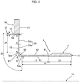
- FIG. 3 is half sectional view in which the silk-hat-shaped externally toothed gear 3 is cut by a plane that includes the center axis 1a thereof.
- the barrel 10 of the externally toothed gear 3 is provided with an external tooth formation portion 12, one end of which is the open end 11, and a cylinder portion 13 having a constant thickness, extending from the external tooth formation portion 12 to the diaphragm 20.
- the external teeth 5 are formed in a portion on an outer circumferential surface of the external tooth formation portion 12.
- the thickness of the cylinder portion 13 is constant in the present example, but the cross-sectional shape of the cylinder portion 13 can also be set so that a wall thickness thereof gradually decreases toward the external tooth formation portion 12 from a diaphragm 20 side.
- the diaphragm 20 is provided with a boss base portion 21, a diaphragm body portion 22, and a curved portion 23.
- the diaphragm body portion 22 extends in a radial direction perpendicular to the center axis 1a.
- the curved portion 23 is continuous with an inner circumferential end A of the diaphragm body portion 22, and curves toward the barrel 10 along the center axis 1a from a radially inward direction.
- a barrel-side end part D of the curved portion 23 is connected to the cylinder portion 13 of the barrel 10.
- the boss base portion 21 extends radially outward from an outer circumferential end C of the diaphragm body portion 22, and is connected to a circular inner circumferential surface 31 of the boss 30.
- an inner circumferential surface portion of the cylinder portion 13 of the barrel 10 of the externally toothed gear 3 is prescribed by an inside straight line 52 extending parallel to the center axis 1a from a region 51 connected to the external tooth formation portion 12 to the barrel-side end part D.
- An outer circumferential surface portion of the cylinder portion 13 is also prescribed by an outside straight line 53 extending parallel to the center axis 1a.
- the cylinder portion 13 having a constant thickness is prescribed by the inside straight line 52 and the outside straight line 53.
- An inner circumferential surface portion of the curved portion 23 of the diaphragm 20 connected to the cylinder portion 13 is prescribed by a recessed arc 55.
- One end of the recessed arc 55 is smoothly connected to the inside straight line 52 at the position of the barrel-side end part D.
- An outer circumferential surface portion of the curved portion 23 is prescribed by an extended-straight-line end portion of the outside straight line 53 extending past the barrel-side end part D, a convex arc 57 smoothly connected to the extended straight line portion 53a, and a straight line portion 58 which is smoothly connected to another end of the convex arc 57 and which extends radially outward.
- a middle position of the curved portion from the inner circumferential end A to the barrel-side end part D is designated as E.
- a curvature radius of the outside convex arc 57 is smaller than the curvature radius of the inside recessed arc 55.
- a wall thickness of the curved portion 23 is greatest at the curved-portion middle position E, gradually increases from the inner circumferential end A to the curved-portion middle position E, and gradually decreases from the curved-portion middle position E to the barrel-side end part D.
- a barrel-side end surface portion of the diaphragm body portion 22 connected to the curved portion 23 is prescribed by a compound recessed curve 59.
- a middle part between the inner circumferential end A and the outer circumferential end C in the diaphragm body portion 22 is designated as B.
- the compound recessed curve 59 is constituted from a recessed arc 59a prescribed from the inner circumferential end A to the middle part B, and a recessed arc 59b prescribed from the middle part B to the outer circumferential end C, for example.
- One end of the recessed arc 59a is smoothly connected to the recessed arc 55 at the position of the inner circumferential end A, and another end of the recessed arc 59a is smoothly connected to the recessed arc 59b.
- An end surface portion on an opposite side of the diaphragm body portion 22 is prescribed by a straight line 58 extending past the inner circumferential end A from an end of a straight line portion 58a.
- the straight line 58 extends to a position of the outer circumferential end C along the radial direction perpendicular to the center axis 1a.
- a thickness of the diaphragm body portion 22 prescribed by the compound recessed curve 59 and the straight line 58 is smallest in the middle part B, gradually increases from the middle part B to the inner circumferential end A, and gradually increases from the middle part B to the outer circumferential end C.
- a barrel-side end surface portion of the boss base portion 21 connected to the outer circumferential end C of the diaphragm body portion 22 is prescribed by an arc portion of the recessed arc 59b of the compound recessed curve 59 that extends past the outer circumferential end C.
- An end of the recessed arc 59b is connected to a straight line 61 that prescribes an end surface of the boss 30 on the same side thereof.
- An end surface portion on an opposite side of the boss base portion 21 is prescribed by a compound recessed curve 63 smoothly connected to an end of the straight line 58 at the position of the outer circumferential end C. Another end of the compound recessed curve 63 is smoothly connected to the circular inner circumferential surface 31 of the boss 30.
- a streamline disclosed in Patent Document 3 JP S61 173851 U ) can be used as the compound recessed curve 63.
- a thickness of the boss base portion 21 increases from the position of the outer circumferential end C to the circular inner circumferential surface 31.
- the thicknesses of the inner circumferential end A, the middle part B, the outer circumferential end C, the barrel-side end part D, and the curved-portion middle position E in the diaphragm 20 are designated as t(A), t(B), t(C), t(D), and t(E), respectively, they are set so that t E > t A > t C > t D > t B is satisfied.
- the thicknesses of the inner circumferential end A, the outer circumferential end C, the barrel-side end part D, and the curved-portion middle position E are preferably set as described below, with reference to the thickness t(B) of the middle part B, the thickness t(B) having the smallest thickness.
- the thickness t(A) of the inner circumferential end A satisfies 1.2 ⁇ t A / t B ⁇ 2.7 ; the thickness t(C) of the outer circumferential end C satisfies 1.0 ⁇ t C / t B ⁇ 2.3 ; the thickness t(D) of the barrel-side end part D satisfies 1.0 ⁇ t D / t B ⁇ 2.3 ; and the thickness t(E) of the curved-portion middle position E satisfies 1.3 ⁇ t E / t B ⁇ 2.8 .
- the thickness t(D) of the barrel-side end part D of the curved portion 23 of the diaphragm 20 is greater than the t(B) of the middle part B, which is the portion of the diaphragm 20 having the smallest thickness, as described above.
- the thickness t(A) of the inner circumferential end A of the diaphragm 20, using the thickness t(B) of the middle part of the diaphragm 20 as a reference, is set so as to be greater than in the case of the conventional silk-hat-shaped externally toothed gear.
- the thickness t(E) of the curved-portion middle position E is set so that the curved-portion middle position E is the portion of the diaphragm 20 having the greatest thickness.
Landscapes
- Engineering & Computer Science (AREA)
- General Engineering & Computer Science (AREA)
- Mechanical Engineering (AREA)
- Retarders (AREA)
Description
- The present invention relates to a silk-hat-type strain wave gearing equipped with a silk-hat-shaped flexible externally toothed gear. More specifically, the present invention relates to an externally toothed gear configured to be used for a strain wave gearing, having enhanced fatigue strength in an operating state in which a high-load torque is applied.
- An externally toothed gear for a silk-hat-type strain wave gearing is provided with a cylindrical barrel, a diaphragm which is continuous with one end of the barrel and spreads radially outward, and an annular thick-walled boss which is continuous with an outer circumferential end of the diaphragm. External teeth are integrally formed in an outer circumferential portion of an opening end on a distal-end side of the barrel.
- In the externally toothed gear having this shape, because the diaphragm spreads toward an outside in a radial direction, an outside diameter of the strain wave gearing is increased relative to a cup-type strain wave gearing equipped with a cup-shaped externally toothed gear. The outside diameter of the diaphragm may be reduced in order to reduce the outside diameter of the strain wave gearing. However, the diaphragm is repeatedly subjected to a large bending stress due to deformation of the barrel, which is repeatedly flexed in the radial direction by a wave generator. It is therefore undesirable to reduce the diameter of the diaphragm, because stress occurring in an inner circumferential end part and an outer circumferential end part of the diaphragm increases in inverse proportion to the diaphragm diameter, and stress becomes concentrated in these portions.
-
Patent Document 1 discloses a silk-hat-type strain wave gearing, wherein stress concentration occurring in a diaphragm of an externally toothed gear that is flexed by a wave generator is mitigated and strength of the diaphragm is increased. In the externally toothed gear disclosed inPatent Document 1, a thickness of the diaphragm is made greater in an inner circumferential end and an outer circumferential end than in a middle part therebetween, and stress concentration in the diaphragm is mitigated. -
Patent Document 2 discloses an improvement of the invention disclosed inPatent Document 1. InPatent Document 2, a thickness of a diaphragm part of an externally toothed gear is at maximum at an inner circumferential end thereof, and is at minimum in a middle part between the inner circumferential end and an outer circumferential end. Stress concentration in the diaphragm part of the externally toothed gear is thereby even further mitigated, and a stress state of the diaphragm can be made uniform. -
Patent Document 3 discloses using a streamline to prescribe a cross-sectional shape of a base portion for attachment of the diaphragm to a boss. -
Patent Document 4 discloses an externally toothed gear having the features of the preamble ofclaim 1. -
- Patent Document 1:
JP H03 118346 U - Patent Document 2:
JP 3580506 B - Patent Document 3:
JP S61 173851 U - Patent Document 4:
EP 0 942 197 A1 - Conventionally, the diaphragm shape of a silk-hat-shaped externally toothed gear was designed through use of a stress analysis that considered ellipsoidal flexural deformation by a wave generator, an applied load torque, and mounting error of the externally toothed gear. With the aim of developing a product that can cope with high load, endurance testing of an externally toothed gear was performed with a further increased current load. It was assumed from current stress analysis that a diaphragm would not experience fatigue fracture even under the aforementioned increased load, but fatigue fracture was confirmed in results of endurance testing of a diaphragm.
- The inventors investigated the cause of diaphragm breakage on the basis of stress analysis and the like, and considered the effect of a thrust force occurring in the externally toothed gear due to load torque in the stress analysis. As a result, the inventors confirmed that a phenomenon of diaphragm breakage observed in an actual endurance test of an externally toothed gear in a state of high load torque can be reproduced in stress analysis as well.
- The inventors focused on the thrust force caused by the load torque, which had not conventionally been considered in designing the diaphragm shape of an externally toothed gear. On this basis, the inventors designed a diaphragm shape while taking into account the effect of the thrust force. The inventors discovered that by taking the thrust force caused by the load torque into account, breakage of the diaphragm can be suppressed even in a state of high load torque, and durability of the externally toothed gear can be increased.
- An object of the present invention is to provide an externally toothed gear configured to be used for a strain wave gearing, provided with a diaphragm shape whereby, on the basis of the above new knowledge, fatigue strength of the diaphragm at high load torque can be enhanced.
- The above object is solved by an externally toothed gear having the features of
claim 1. Advantageous further developments are set out in the dependent claims. - In the present invention, the thickness of the diaphragm is made greater in the inner circumferential end and outer circumferential end than in the middle part in the diaphragm body portion, and the thickness of the inner circumferential end is greater than that of the outer circumferential end. The thickness of the barrel-side end part in the curved portion of the diaphragm is also greater than that of the middle part, which has the smallest thickness of the diaphragm body portion, and the thickness of the barrel-side end part is less than that of the outer circumferential end of the diaphragm body portion.
- By setting the thickness of each portion of the diaphragm in this manner, stress can be smoothly distributed along the diaphragm from the inner circumferential end to the outer circumferential end thereof. In particular, concentration of stress that occurs in the diaphragm due to a thrust force from the load torque can be mitigated, and the maximum stress can be reduced. As a result, it is possible to prevent or suppress breakage of the diaphragm in an operating state of high load torque, and durability of the externally toothed gear can be increased.
- Preferably, with reference to the thickness t(B) of the middle part of the diaphragm body portion,
- the thickness t(A) of the inner circumferential end of the diaphragm body portion satisfies


- Specifically, the thickness t(D) of the barrel-side end part of the curved portion of the diaphragm is set so as to be greater than the thickness t(B) of the middle part of the diaphragm body portion. The thickness t(A) of the inner circumferential end of the diaphragm body portion, using the thickness t(B) of the middle part as a reference, is also set so as to be greater than in the case of the conventional externally toothed gear.
- By setting the thickness of each part of the diaphragm in this manner, stress concentration that occurs in the diaphragm due to the thrust force can be even further mitigated, and the maximum stress can be significantly reduced in an operating state of high load torque. Fatigue strength of the diaphragm can thereby be enhanced.
- In the curved portion of the diaphragm, a middle position extending from the inner circumferential end connected to the diaphragm body portion to the barrel-side end part connected to the barrel is referred to herein as a curved-portion middle position. In this case, between the inner circumferential end of the curved portion and the curved-portion middle position thereof, the thickness of the diaphragm preferably gradually increases from the inner circumferential end to the curved-portion middle position and gradually decreases from the curved-portion middle position to the barrel-side end part, and
preferably,

- In the barrel, a thickness of a cylinder portion extending from an external tooth formation portion, in which external teeth are formed, to the barrel-side end part of the curved portion of the diaphragm can be configured so as to be constant, and to be the same as the thickness t(D) of the barrel-side end part.
-
-
FIG. 1 is a schematic longitudinal sectional view of a silk-hat-type strain wave gearing according to an embodiment of the present invention; -
FIG. 2 is an explanatory drawing illustrating a state of meshing of teeth of the strain wave gearing ofFIG. 1 ; and -
FIG. 3 is a half sectional view illustrating an externally toothed gear ofFIG. 1 . - Embodiments of the silk-hat-type strain wave gearing to which the present invention is applied will be described below with reference to the accompanying drawings.
-
FIG. 1 is a schematic longitudinal sectional view illustrating the overall structure of the silk-hat-type strain wave gearing according to the present embodiment, andFIG. 2 is an explanatory diagram illustrating a state of meshing of teeth. Astrain wave gearing 1 is constituted from an annular rigid internallytoothed gear 2, a silk-hat-shaped flexible externallytoothed gear 3 disposed coaxially therewith and on an inside thereof, and awave generator 4 which has an ellipsoidal outline and is fitted inside the externallytoothed gear 3. - The externally
toothed gear 3 is provided with abarrel 10, adiaphragm 20, and aboss 30, and is silk-hat shaped overall. Thebarrel 10 is cylindrical and capable of flexing. One end of thebarrel 10 is anopen end 11. Thediaphragm 20 spreads radially outward continuously with another end of thebarrel 10. Theannular boss 30 having a rectangular cross section is formed continuously with an outer circumferential edge of thediaphragm 20. Theboss 30 is a rigid portion for attaching the externallytoothed gear 3 to another member (not illustrated). - The
wave generator 4 is constituted from ahollow hub 41, an ellipsoidalrigid cam plate 42 fitted on an outer circumference of thehollow hub 41, and a wave bearing 43 fitted on an outer circumference of therigid cam plate 42. An external tooth formation portion of the flexible externallytoothed gear 3 in whichexternal teeth 5 thereof are formed is ellipsoidally flexed by thewave generator 4. Theexternal teeth 5 of the externallytoothed gear 3 are meshed withinternal teeth 6 of the rigid internallytoothed gear 2 at two locations positioned at both ends of a major axis of an ellipse. - When the
wave generator 4 rotates about acenter axis 1a, the meshing positions of bothgears toothed gear 3 and the internallytoothed gear 2 in accordance with a difference between the number ofexternal teeth 5 and the number ofinternal teeth 6. For example, in a configuration in which the internallytoothed gear 2 is fixed and thewave generator 4 is a high-speed rotational input element, the externallytoothed gear 3 becomes a reduced-speed rotational output element, and a rotational output that is reduced in speed in accordance with the difference in the number of teeth between both gears. -
FIG. 3 is half sectional view in which the silk-hat-shaped externallytoothed gear 3 is cut by a plane that includes thecenter axis 1a thereof. Thebarrel 10 of the externallytoothed gear 3 is provided with an externaltooth formation portion 12, one end of which is theopen end 11, and acylinder portion 13 having a constant thickness, extending from the externaltooth formation portion 12 to thediaphragm 20. Theexternal teeth 5 are formed in a portion on an outer circumferential surface of the externaltooth formation portion 12. - The thickness of the
cylinder portion 13 is constant in the present example, but the cross-sectional shape of thecylinder portion 13 can also be set so that a wall thickness thereof gradually decreases toward the externaltooth formation portion 12 from adiaphragm 20 side. - The
diaphragm 20 is provided with aboss base portion 21, adiaphragm body portion 22, and acurved portion 23. Thediaphragm body portion 22 extends in a radial direction perpendicular to thecenter axis 1a. Thecurved portion 23 is continuous with an inner circumferential end A of thediaphragm body portion 22, and curves toward thebarrel 10 along thecenter axis 1a from a radially inward direction. A barrel-side end part D of thecurved portion 23 is connected to thecylinder portion 13 of thebarrel 10. Theboss base portion 21 extends radially outward from an outer circumferential end C of thediaphragm body portion 22, and is connected to a circular innercircumferential surface 31 of theboss 30. - More specifically, an inner circumferential surface portion of the
cylinder portion 13 of thebarrel 10 of the externallytoothed gear 3 is prescribed by an insidestraight line 52 extending parallel to thecenter axis 1a from aregion 51 connected to the externaltooth formation portion 12 to the barrel-side end part D. An outer circumferential surface portion of thecylinder portion 13 is also prescribed by an outsidestraight line 53 extending parallel to thecenter axis 1a. Thecylinder portion 13 having a constant thickness is prescribed by the insidestraight line 52 and the outsidestraight line 53. - An inner circumferential surface portion of the
curved portion 23 of thediaphragm 20 connected to thecylinder portion 13 is prescribed by a recessedarc 55. One end of the recessedarc 55 is smoothly connected to the insidestraight line 52 at the position of the barrel-side end part D. An outer circumferential surface portion of thecurved portion 23 is prescribed by an extended-straight-line end portion of the outsidestraight line 53 extending past the barrel-side end part D, aconvex arc 57 smoothly connected to the extendedstraight line portion 53a, and astraight line portion 58 which is smoothly connected to another end of theconvex arc 57 and which extends radially outward. - In the
curved portion 23, a middle position of the curved portion from the inner circumferential end A to the barrel-side end part D is designated as E. In thecurved portion 23, a curvature radius of the outsideconvex arc 57 is smaller than the curvature radius of the inside recessedarc 55. A wall thickness of thecurved portion 23 is greatest at the curved-portion middle position E, gradually increases from the inner circumferential end A to the curved-portion middle position E, and gradually decreases from the curved-portion middle position E to the barrel-side end part D. - A barrel-side end surface portion of the
diaphragm body portion 22 connected to thecurved portion 23 is prescribed by a compound recessedcurve 59. A middle part between the inner circumferential end A and the outer circumferential end C in thediaphragm body portion 22 is designated as B. The compound recessedcurve 59 is constituted from a recessedarc 59a prescribed from the inner circumferential end A to the middle part B, and a recessedarc 59b prescribed from the middle part B to the outer circumferential end C, for example. One end of the recessedarc 59a is smoothly connected to the recessedarc 55 at the position of the inner circumferential end A, and another end of the recessedarc 59a is smoothly connected to the recessedarc 59b. - An end surface portion on an opposite side of the
diaphragm body portion 22 is prescribed by astraight line 58 extending past the inner circumferential end A from an end of astraight line portion 58a. Thestraight line 58 extends to a position of the outer circumferential end C along the radial direction perpendicular to thecenter axis 1a. - A thickness of the
diaphragm body portion 22 prescribed by the compound recessedcurve 59 and thestraight line 58 is smallest in the middle part B, gradually increases from the middle part B to the inner circumferential end A, and gradually increases from the middle part B to the outer circumferential end C. - A barrel-side end surface portion of the
boss base portion 21 connected to the outer circumferential end C of thediaphragm body portion 22 is prescribed by an arc portion of the recessedarc 59b of the compound recessedcurve 59 that extends past the outer circumferential end C. An end of the recessedarc 59b is connected to astraight line 61 that prescribes an end surface of theboss 30 on the same side thereof. - An end surface portion on an opposite side of the
boss base portion 21 is prescribed by a compound recessedcurve 63 smoothly connected to an end of thestraight line 58 at the position of the outer circumferential end C. Another end of the compound recessedcurve 63 is smoothly connected to the circular innercircumferential surface 31 of theboss 30. A streamline disclosed in Patent Document 3 (JP S61 173851 U curve 63. A thickness of theboss base portion 21 increases from the position of the outer circumferential end C to the circular innercircumferential surface 31. - Where thicknesses of the inner circumferential end A, the middle part B, the outer circumferential end C, the barrel-side end part D, and the curved-portion middle position E in the
diaphragm 20, the thicknesses are designated as t(A), t(B), t(C), t(D), and t(E), respectively, they are set so that
- The thicknesses of the inner circumferential end A, the outer circumferential end C, the barrel-side end part D, and the curved-portion middle position E are preferably set as described below, with reference to the thickness t(B) of the middle part B, the thickness t(B) having the smallest thickness.
- The thickness t(A) of the inner circumferential end A satisfies


- In the externally
toothed gear 3 in the present example, the thickness t(D) of the barrel-side end part D of thecurved portion 23 of thediaphragm 20 is greater than the t(B) of the middle part B, which is the portion of thediaphragm 20 having the smallest thickness, as described above. The thickness t(A) of the inner circumferential end A of thediaphragm 20, using the thickness t(B) of the middle part of thediaphragm 20 as a reference, is set so as to be greater than in the case of the conventional silk-hat-shaped externally toothed gear. Furthermore, the thickness t(E) of the curved-portion middle position E is set so that the curved-portion middle position E is the portion of thediaphragm 20 having the greatest thickness. - When a thrust force acts on the silk-hat-shaped externally
toothed gear 3, stress is concentrated in a portion of thediaphragm body portion 22 near the outer circumferential end C and a portion of thediaphragm body portion 22 near the inner circumferential end A. Through experimentation, the inventors confirmed that when the thickness of each part of the externallytoothed gear 3 is set as described above, concentrated stress due to thrust force in an operating state of high load torque can be reduced by 20-40% in each model number of silk-hat-type strain wave gearing. The inventors also confirmed that setting the thickness of thediaphragm 20 in the manner described above is effective for suppressing or avoiding breakage of thediaphragm 20 in an operating state of high load torque. The inventors furthermore confirmed that setting the thickness of thediaphragm 20 in the manner described above is effective for enhancing torsional rigidity and buckling strength of the externallytoothed gear 3.
Claims (6)
- An externally toothed gear (3) configured to be used for a strain wave gearing (1), in which the externally toothed gear (3) can be ellipsoidally flexed by a wave generator (4) to form a state of partial meshing with a rigid internally toothed gear (2), the externally toothed gear (3) comprising:a cylindrical barrel (10) provided with one end being an open end (11); external teeth (5) formed on a portion of an outer circumferential surface of the barrel (10) on a side of the open end (11) thereof; a diaphragm (20) which is continuous with another end of the barrel (10) and spreads outward in a radial direction of the barrel (10); and an annular boss (30) formed continuously with an outer circumferential end (C) of the diaphragm (20),wherein the diaphragm (20) comprises:a diaphragm body portion (22) extending in the radial direction;a curved portion (23) which is continuous with an inner circumferential end (A) of the diaphragm body portion (22), curves toward the barrel (10) along a center axis (1a) from a direction inward in the radial direction, and is connected to the barrel (10); anda boss base portion (21) which extends outward in the radial direction from the outer circumferential end (C) of the diaphragm body portion (22), and is connected to an inner circumferential surface (31) of the boss (30); andwherein a thickness of the diaphragm (20) gradually decreases from a position of the boss base portion (21) connected to the inner circumferential surface (31) of the boss (30) to a middle part (B) between the outer circumferential end (C) and the inner circumferential end (A) in the diaphragm body portion (22), and the thickness of the diaphragm (20) gradually increases from the middle part (B) to the inner circumferential end (A) of the diaphragm body portion (22);characterized in thatthicknesses of the inner circumferential end (A), the middle part (B), and the outer circumferential end (C) of the diaphragm (20), and a thickness of a barrel-side end part (D) of the curved portion (23) connected to the barrel (10) satisfy
 where t(A) is the thickness of the inner circumferential end (A), t(B) is the thickness of the middle part (B), t(C) is the thickness of the outer circumferential end (C), and t(D) is the thickness of the barrel-side end part (D).
 - The externally toothed gear (3) for the strain wave gearing (1) according to claim 1,
wherein, with reference to the thickness t(B) of the middle part (B) of the diaphragm body portion (22),
the thickness t(A) of the inner circumferential end (A) satisfies


- The externally toothed gear (3) for the strain wave gearing (1) according to claim 1,
wherein the thickness of the diaphragm (20) gradually increases from the inner circumferential end (A) to a curved-portion middle position (E) between the inner circumferential end (A) and the barrel-side end part (D), and gradually decreases from the curved-portion middle position (E) to the barrel-side end part (D),
wherein a thickness t(E) of the curved-portion middle position (E) satisfies

- The externally toothed gear (3) for the strain wave gearing (1) according to claim 1,
wherein the barrel (10) comprises an external tooth formation portion (12) where the external teeth (5) are formed, and a cylinder portion (13) from the external tooth formation portion (12) to the barrel-side end part (D) of the curved portion (23), and
a thickness of the cylinder portion (13) is constant and is the same as the thickness t(D) of the barrel-side end part (D). - The externally toothed gear (3) for the strain wave gearing (1) according to claim 1,
wherein the thickness of the diaphragm (20) gradually increases from the inner circumferential end (A) of the curved portion (23) to a curved-portion middle position (E) between the inner circumferential end (A) and the barrel-side end part (D), and gradually decreases from the curved-portion middle position (E) to the barrel-side end part (D),
wherein a thickness t(E) of the curved-portion middle position (E) satisfies


- A strain wave gearing (1) comprising:an annular rigid internally toothed gear (2);the externally toothed gear (3) as set forth in any one of claims 1 to 5; anda wave generator (4) for flexing the externally toothed gear (3) in a radial direction thereof to partially mesh with the internally toothed gear (2) and for moving meshed positions between the gears in a circumferential direction.
Applications Claiming Priority (1)
| Application Number | Priority Date | Filing Date | Title |
|---|---|---|---|
| PCT/JP2016/085642 WO2018100701A1 (en) | 2016-11-30 | 2016-11-30 | External gear of wave gear device |
Publications (3)
| Publication Number | Publication Date |
|---|---|
| EP3550178A1 EP3550178A1 (en) | 2019-10-09 |
| EP3550178A4 EP3550178A4 (en) | 2020-04-22 |
| EP3550178B1 true EP3550178B1 (en) | 2021-03-10 |
Family
ID=62242000
Family Applications (1)
| Application Number | Title | Priority Date | Filing Date |
|---|---|---|---|
| EP16923084.4A Active EP3550178B1 (en) | 2016-11-30 | 2016-11-30 | External gear of wave gear device |
Country Status (7)
| Country | Link |
|---|---|
| US (1) | US10890239B2 (en) |
| EP (1) | EP3550178B1 (en) |
| JP (1) | JP6656781B2 (en) |
| KR (1) | KR102136987B1 (en) |
| CN (1) | CN109983251B (en) |
| TW (1) | TWI735644B (en) |
| WO (1) | WO2018100701A1 (en) |
Families Citing this family (6)
| Publication number | Priority date | Publication date | Assignee | Title |
|---|---|---|---|---|
| CN109139855A (en) * | 2018-10-03 | 2019-01-04 | 凌子龙 | Double flexbile gear harmonic wave speed reducing machines |
| CN109578551B (en) * | 2018-12-06 | 2020-08-21 | 北京工业大学 | Harmonic reducer ware flexbile gear cup based on continuous transition curve |
| CN111255876B (en) * | 2020-01-20 | 2021-02-09 | 珠海格力电器股份有限公司 | Flexible gear and harmonic reducer |
| JP7631771B2 (en) | 2020-12-11 | 2025-02-19 | セイコーエプソン株式会社 | Gearing and robots |
| JP2022096109A (en) * | 2020-12-17 | 2022-06-29 | セイコーエプソン株式会社 | Gear device and robot |
| JP7722905B2 (en) * | 2021-11-22 | 2025-08-13 | ニデックドライブテクノロジー株式会社 | Flexible external gear, strain wave reducer, and robot |
Family Cites Families (19)
| Publication number | Priority date | Publication date | Assignee | Title |
|---|---|---|---|---|
| JPS58506B2 (en) | 1976-03-12 | 1983-01-06 | 三菱マテリアル株式会社 | Bright corrosion resistant Al alloy for die casting |
| JPS61173851A (en) | 1985-01-29 | 1986-08-05 | Seiko Seiki Co Ltd | Method of grinding internal surface |
| JPS61173851U (en) | 1985-04-19 | 1986-10-29 | ||
| JPH03118346A (en) | 1989-09-30 | 1991-05-20 | Sekisui Chem Co Ltd | Production of ester |
| JPH03118346U (en) | 1990-03-16 | 1991-12-06 | ||
| JP2535503Y2 (en) * | 1991-05-20 | 1997-05-14 | 株式会社ハーモニック・ドライブ・システムズ | Meshing structure of external teeth and internal teeth in cup-type gear type harmonic transmission |
| JP3580506B2 (en) | 1994-12-14 | 2004-10-27 | 株式会社ハーモニック・ドライブ・システムズ | Silk hat type flexible meshing gear device |
| WO1996018833A1 (en) | 1994-12-14 | 1996-06-20 | Harmonic Drive Systems Inc. | Silk hat type flexible mesh engagement gear device |
| JP3768261B2 (en) * | 1995-05-19 | 2006-04-19 | 株式会社ハーモニック・ドライブ・システムズ | Flat type wave gear device |
| JPH09273609A (en) * | 1996-04-04 | 1997-10-21 | Harmonic Drive Syst Ind Co Ltd | Top hat type flexible meshing gear unit |
| US6202508B1 (en) * | 1997-10-02 | 2001-03-20 | Harmonic Drive Systems, Inc. | Silk hat flexible engagement gear device |
| JP4133018B2 (en) * | 2002-06-21 | 2008-08-13 | 株式会社ハーモニック・ドライブ・システムズ | Method of assembling a wave generator for a top hat type wave gear device, and a top hat-shaped flexible external gear used in the method |
| JP3118346U (en) | 2005-10-19 | 2006-01-26 | 開発コンクリート株式会社 | Seawall block |
| JP2007303592A (en) * | 2006-05-12 | 2007-11-22 | Honda Motor Co Ltd | Wave gear device |
| WO2013024511A1 (en) * | 2011-08-17 | 2013-02-21 | 株式会社ハーモニック・ドライブ・システムズ | Flexible externally toothed gear for wave gear device |
| CN103562593B (en) * | 2012-05-31 | 2016-03-16 | 谐波传动系统有限公司 | Wave gear device and flexible external tooth gear |
| JP2015102181A (en) * | 2013-11-26 | 2015-06-04 | キヤノン株式会社 | Strain wave gearing decelerator |
| JP6614988B2 (en) * | 2016-02-08 | 2019-12-04 | 株式会社ハーモニック・ドライブ・システムズ | Cup-shaped flexible external gear and wave gear device |
| TWI641771B (en) * | 2016-12-29 | 2018-11-21 | 財團法人工業技術研究院 | Harmonic driving device |
-
2016
- 2016-11-30 EP EP16923084.4A patent/EP3550178B1/en active Active
- 2016-11-30 WO PCT/JP2016/085642 patent/WO2018100701A1/en not_active Ceased
- 2016-11-30 US US16/348,884 patent/US10890239B2/en active Active
- 2016-11-30 KR KR1020197015550A patent/KR102136987B1/en active Active
- 2016-11-30 CN CN201680090914.9A patent/CN109983251B/en active Active
- 2016-11-30 JP JP2018553592A patent/JP6656781B2/en active Active
-
2017
- 2017-09-06 TW TW106130366A patent/TWI735644B/en active
Non-Patent Citations (1)
| Title |
|---|
| None * |
Also Published As
| Publication number | Publication date |
|---|---|
| JP6656781B2 (en) | 2020-03-04 |
| US10890239B2 (en) | 2021-01-12 |
| EP3550178A1 (en) | 2019-10-09 |
| JPWO2018100701A1 (en) | 2019-10-17 |
| TWI735644B (en) | 2021-08-11 |
| EP3550178A4 (en) | 2020-04-22 |
| CN109983251B (en) | 2022-04-05 |
| TW201821715A (en) | 2018-06-16 |
| WO2018100701A1 (en) | 2018-06-07 |
| US20190277383A1 (en) | 2019-09-12 |
| KR102136987B1 (en) | 2020-07-23 |
| CN109983251A (en) | 2019-07-05 |
| KR20190077478A (en) | 2019-07-03 |
Similar Documents
| Publication | Publication Date | Title |
|---|---|---|
| EP3550178B1 (en) | External gear of wave gear device | |
| JP5826275B2 (en) | Flexible external gear of wave gear device | |
| JP5936195B2 (en) | Wave gear device and flexible external gear | |
| US10352427B2 (en) | Cup-shaped flexible externally toothed gear and cup-type strain wave gearing | |
| JP4685383B2 (en) | Wave gear device | |
| JP5925387B2 (en) | Wave generator and wave gear device | |
| EP3667120B1 (en) | Wave gear device | |
| EP3173657B1 (en) | Dual-type wave gear device | |
| US20180306276A1 (en) | Flexible external gear and strain wave gearing | |
| EP3567278B1 (en) | Cup-type harmonic gear device | |
| WO2017022062A1 (en) | Strain wave gearing device | |
| JPWO2019106773A1 (en) | Wave gear device | |
| WO2016092636A1 (en) | Pass-type meshing negative-deflection harmonic drive gearing | |
| KR20210008424A (en) | Hollow type wave gear device | |
| US20210131543A1 (en) | Strain wave gearing | |
| EP3795858A1 (en) | Wave gear device | |
| EP3351822A1 (en) | Wave motion generator for wave motion gear device |
Legal Events
| Date | Code | Title | Description |
|---|---|---|---|
| STAA | Information on the status of an ep patent application or granted ep patent |
Free format text: STATUS: THE INTERNATIONAL PUBLICATION HAS BEEN MADE |
|
| PUAI | Public reference made under article 153(3) epc to a published international application that has entered the european phase |
Free format text: ORIGINAL CODE: 0009012 |
|
| STAA | Information on the status of an ep patent application or granted ep patent |
Free format text: STATUS: REQUEST FOR EXAMINATION WAS MADE |
|
| 17P | Request for examination filed |
Effective date: 20190510 |
|
| AK | Designated contracting states |
Kind code of ref document: A1 Designated state(s): AL AT BE BG CH CY CZ DE DK EE ES FI FR GB GR HR HU IE IS IT LI LT LU LV MC MK MT NL NO PL PT RO RS SE SI SK SM TR |
|
| AX | Request for extension of the european patent |
Extension state: BA ME |
|
| DAV | Request for validation of the european patent (deleted) | ||
| DAX | Request for extension of the european patent (deleted) | ||
| A4 | Supplementary search report drawn up and despatched |
Effective date: 20200324 |
|
| RIC1 | Information provided on ipc code assigned before grant |
Ipc: F16H 49/00 20060101ALI20200318BHEP Ipc: F16H 1/32 20060101AFI20200318BHEP |
|
| TPAC | Observations filed by third parties |
Free format text: ORIGINAL CODE: EPIDOSNTIPA |
|
| GRAP | Despatch of communication of intention to grant a patent |
Free format text: ORIGINAL CODE: EPIDOSNIGR1 |
|
| STAA | Information on the status of an ep patent application or granted ep patent |
Free format text: STATUS: GRANT OF PATENT IS INTENDED |
|
| INTG | Intention to grant announced |
Effective date: 20201008 |
|
| GRAS | Grant fee paid |
Free format text: ORIGINAL CODE: EPIDOSNIGR3 |
|
| GRAA | (expected) grant |
Free format text: ORIGINAL CODE: 0009210 |
|
| STAA | Information on the status of an ep patent application or granted ep patent |
Free format text: STATUS: THE PATENT HAS BEEN GRANTED |
|
| AK | Designated contracting states |
Kind code of ref document: B1 Designated state(s): AL AT BE BG CH CY CZ DE DK EE ES FI FR GB GR HR HU IE IS IT LI LT LU LV MC MK MT NL NO PL PT RO RS SE SI SK SM TR |
|
| REG | Reference to a national code |
Ref country code: GB Ref legal event code: FG4D |
|
| REG | Reference to a national code |
Ref country code: AT Ref legal event code: REF Ref document number: 1370140 Country of ref document: AT Kind code of ref document: T Effective date: 20210315 Ref country code: CH Ref legal event code: EP |
|
| REG | Reference to a national code |
Ref country code: IE Ref legal event code: FG4D |
|
| REG | Reference to a national code |
Ref country code: DE Ref legal event code: R096 Ref document number: 602016054284 Country of ref document: DE |
|
| REG | Reference to a national code |
Ref country code: LT Ref legal event code: MG9D |
|
| PG25 | Lapsed in a contracting state [announced via postgrant information from national office to epo] |
Ref country code: NO Free format text: LAPSE BECAUSE OF FAILURE TO SUBMIT A TRANSLATION OF THE DESCRIPTION OR TO PAY THE FEE WITHIN THE PRESCRIBED TIME-LIMIT Effective date: 20210610 Ref country code: FI Free format text: LAPSE BECAUSE OF FAILURE TO SUBMIT A TRANSLATION OF THE DESCRIPTION OR TO PAY THE FEE WITHIN THE PRESCRIBED TIME-LIMIT Effective date: 20210310 Ref country code: HR Free format text: LAPSE BECAUSE OF FAILURE TO SUBMIT A TRANSLATION OF THE DESCRIPTION OR TO PAY THE FEE WITHIN THE PRESCRIBED TIME-LIMIT Effective date: 20210310 Ref country code: GR Free format text: LAPSE BECAUSE OF FAILURE TO SUBMIT A TRANSLATION OF THE DESCRIPTION OR TO PAY THE FEE WITHIN THE PRESCRIBED TIME-LIMIT Effective date: 20210611 Ref country code: BG Free format text: LAPSE BECAUSE OF FAILURE TO SUBMIT A TRANSLATION OF THE DESCRIPTION OR TO PAY THE FEE WITHIN THE PRESCRIBED TIME-LIMIT Effective date: 20210610 Ref country code: LT Free format text: LAPSE BECAUSE OF FAILURE TO SUBMIT A TRANSLATION OF THE DESCRIPTION OR TO PAY THE FEE WITHIN THE PRESCRIBED TIME-LIMIT Effective date: 20210310 |
|
| REG | Reference to a national code |
Ref country code: AT Ref legal event code: MK05 Ref document number: 1370140 Country of ref document: AT Kind code of ref document: T Effective date: 20210310 |
|
| REG | Reference to a national code |
Ref country code: NL Ref legal event code: MP Effective date: 20210310 |
|
| PG25 | Lapsed in a contracting state [announced via postgrant information from national office to epo] |
Ref country code: SE Free format text: LAPSE BECAUSE OF FAILURE TO SUBMIT A TRANSLATION OF THE DESCRIPTION OR TO PAY THE FEE WITHIN THE PRESCRIBED TIME-LIMIT Effective date: 20210310 Ref country code: RS Free format text: LAPSE BECAUSE OF FAILURE TO SUBMIT A TRANSLATION OF THE DESCRIPTION OR TO PAY THE FEE WITHIN THE PRESCRIBED TIME-LIMIT Effective date: 20210310 Ref country code: LV Free format text: LAPSE BECAUSE OF FAILURE TO SUBMIT A TRANSLATION OF THE DESCRIPTION OR TO PAY THE FEE WITHIN THE PRESCRIBED TIME-LIMIT Effective date: 20210310 |
|
| PG25 | Lapsed in a contracting state [announced via postgrant information from national office to epo] |
Ref country code: NL Free format text: LAPSE BECAUSE OF FAILURE TO SUBMIT A TRANSLATION OF THE DESCRIPTION OR TO PAY THE FEE WITHIN THE PRESCRIBED TIME-LIMIT Effective date: 20210310 |
|
| PG25 | Lapsed in a contracting state [announced via postgrant information from national office to epo] |
Ref country code: AT Free format text: LAPSE BECAUSE OF FAILURE TO SUBMIT A TRANSLATION OF THE DESCRIPTION OR TO PAY THE FEE WITHIN THE PRESCRIBED TIME-LIMIT Effective date: 20210310 Ref country code: SM Free format text: LAPSE BECAUSE OF FAILURE TO SUBMIT A TRANSLATION OF THE DESCRIPTION OR TO PAY THE FEE WITHIN THE PRESCRIBED TIME-LIMIT Effective date: 20210310 Ref country code: CZ Free format text: LAPSE BECAUSE OF FAILURE TO SUBMIT A TRANSLATION OF THE DESCRIPTION OR TO PAY THE FEE WITHIN THE PRESCRIBED TIME-LIMIT Effective date: 20210310 Ref country code: EE Free format text: LAPSE BECAUSE OF FAILURE TO SUBMIT A TRANSLATION OF THE DESCRIPTION OR TO PAY THE FEE WITHIN THE PRESCRIBED TIME-LIMIT Effective date: 20210310 |
|
| PG25 | Lapsed in a contracting state [announced via postgrant information from national office to epo] |
Ref country code: IS Free format text: LAPSE BECAUSE OF FAILURE TO SUBMIT A TRANSLATION OF THE DESCRIPTION OR TO PAY THE FEE WITHIN THE PRESCRIBED TIME-LIMIT Effective date: 20210710 Ref country code: SK Free format text: LAPSE BECAUSE OF FAILURE TO SUBMIT A TRANSLATION OF THE DESCRIPTION OR TO PAY THE FEE WITHIN THE PRESCRIBED TIME-LIMIT Effective date: 20210310 Ref country code: RO Free format text: LAPSE BECAUSE OF FAILURE TO SUBMIT A TRANSLATION OF THE DESCRIPTION OR TO PAY THE FEE WITHIN THE PRESCRIBED TIME-LIMIT Effective date: 20210310 Ref country code: PL Free format text: LAPSE BECAUSE OF FAILURE TO SUBMIT A TRANSLATION OF THE DESCRIPTION OR TO PAY THE FEE WITHIN THE PRESCRIBED TIME-LIMIT Effective date: 20210310 Ref country code: PT Free format text: LAPSE BECAUSE OF FAILURE TO SUBMIT A TRANSLATION OF THE DESCRIPTION OR TO PAY THE FEE WITHIN THE PRESCRIBED TIME-LIMIT Effective date: 20210712 |
|
| REG | Reference to a national code |
Ref country code: DE Ref legal event code: R097 Ref document number: 602016054284 Country of ref document: DE |
|
| PLBE | No opposition filed within time limit |
Free format text: ORIGINAL CODE: 0009261 |
|
| STAA | Information on the status of an ep patent application or granted ep patent |
Free format text: STATUS: NO OPPOSITION FILED WITHIN TIME LIMIT |
|
| PG25 | Lapsed in a contracting state [announced via postgrant information from national office to epo] |
Ref country code: ES Free format text: LAPSE BECAUSE OF FAILURE TO SUBMIT A TRANSLATION OF THE DESCRIPTION OR TO PAY THE FEE WITHIN THE PRESCRIBED TIME-LIMIT Effective date: 20210310 Ref country code: DK Free format text: LAPSE BECAUSE OF FAILURE TO SUBMIT A TRANSLATION OF THE DESCRIPTION OR TO PAY THE FEE WITHIN THE PRESCRIBED TIME-LIMIT Effective date: 20210310 Ref country code: AL Free format text: LAPSE BECAUSE OF FAILURE TO SUBMIT A TRANSLATION OF THE DESCRIPTION OR TO PAY THE FEE WITHIN THE PRESCRIBED TIME-LIMIT Effective date: 20210310 |
|
| 26N | No opposition filed |
Effective date: 20211213 |
|
| PG25 | Lapsed in a contracting state [announced via postgrant information from national office to epo] |
Ref country code: SI Free format text: LAPSE BECAUSE OF FAILURE TO SUBMIT A TRANSLATION OF THE DESCRIPTION OR TO PAY THE FEE WITHIN THE PRESCRIBED TIME-LIMIT Effective date: 20210310 |
|
| PG25 | Lapsed in a contracting state [announced via postgrant information from national office to epo] |
Ref country code: IT Free format text: LAPSE BECAUSE OF FAILURE TO SUBMIT A TRANSLATION OF THE DESCRIPTION OR TO PAY THE FEE WITHIN THE PRESCRIBED TIME-LIMIT Effective date: 20210310 |
|
| PG25 | Lapsed in a contracting state [announced via postgrant information from national office to epo] |
Ref country code: IS Free format text: LAPSE BECAUSE OF FAILURE TO SUBMIT A TRANSLATION OF THE DESCRIPTION OR TO PAY THE FEE WITHIN THE PRESCRIBED TIME-LIMIT Effective date: 20210710 |
|
| PG25 | Lapsed in a contracting state [announced via postgrant information from national office to epo] |
Ref country code: MC Free format text: LAPSE BECAUSE OF FAILURE TO SUBMIT A TRANSLATION OF THE DESCRIPTION OR TO PAY THE FEE WITHIN THE PRESCRIBED TIME-LIMIT Effective date: 20210310 |
|
| REG | Reference to a national code |
Ref country code: CH Ref legal event code: PL |
|
| GBPC | Gb: european patent ceased through non-payment of renewal fee |
Effective date: 20211130 |
|
| PG25 | Lapsed in a contracting state [announced via postgrant information from national office to epo] |
Ref country code: LU Free format text: LAPSE BECAUSE OF NON-PAYMENT OF DUE FEES Effective date: 20211130 Ref country code: BE Free format text: LAPSE BECAUSE OF NON-PAYMENT OF DUE FEES Effective date: 20211130 |
|
| REG | Reference to a national code |
Ref country code: BE Ref legal event code: MM Effective date: 20211130 |
|
| PG25 | Lapsed in a contracting state [announced via postgrant information from national office to epo] |
Ref country code: LI Free format text: LAPSE BECAUSE OF NON-PAYMENT OF DUE FEES Effective date: 20211130 Ref country code: CH Free format text: LAPSE BECAUSE OF NON-PAYMENT OF DUE FEES Effective date: 20211130 |
|
| PG25 | Lapsed in a contracting state [announced via postgrant information from national office to epo] |
Ref country code: IE Free format text: LAPSE BECAUSE OF NON-PAYMENT OF DUE FEES Effective date: 20211130 Ref country code: GB Free format text: LAPSE BECAUSE OF NON-PAYMENT OF DUE FEES Effective date: 20211130 |
|
| PG25 | Lapsed in a contracting state [announced via postgrant information from national office to epo] |
Ref country code: CY Free format text: LAPSE BECAUSE OF FAILURE TO SUBMIT A TRANSLATION OF THE DESCRIPTION OR TO PAY THE FEE WITHIN THE PRESCRIBED TIME-LIMIT Effective date: 20210310 |
|
| PG25 | Lapsed in a contracting state [announced via postgrant information from national office to epo] |
Ref country code: HU Free format text: LAPSE BECAUSE OF FAILURE TO SUBMIT A TRANSLATION OF THE DESCRIPTION OR TO PAY THE FEE WITHIN THE PRESCRIBED TIME-LIMIT; INVALID AB INITIO Effective date: 20161130 |
|
| PG25 | Lapsed in a contracting state [announced via postgrant information from national office to epo] |
Ref country code: MK Free format text: LAPSE BECAUSE OF FAILURE TO SUBMIT A TRANSLATION OF THE DESCRIPTION OR TO PAY THE FEE WITHIN THE PRESCRIBED TIME-LIMIT Effective date: 20210310 |
|
| PG25 | Lapsed in a contracting state [announced via postgrant information from national office to epo] |
Ref country code: TR Free format text: LAPSE BECAUSE OF FAILURE TO SUBMIT A TRANSLATION OF THE DESCRIPTION OR TO PAY THE FEE WITHIN THE PRESCRIBED TIME-LIMIT Effective date: 20210310 |
|
| PG25 | Lapsed in a contracting state [announced via postgrant information from national office to epo] |
Ref country code: MT Free format text: LAPSE BECAUSE OF FAILURE TO SUBMIT A TRANSLATION OF THE DESCRIPTION OR TO PAY THE FEE WITHIN THE PRESCRIBED TIME-LIMIT Effective date: 20210310 |
|
| PGFP | Annual fee paid to national office [announced via postgrant information from national office to epo] |
Ref country code: FR Payment date: 20250930 Year of fee payment: 10 |
|
| PGFP | Annual fee paid to national office [announced via postgrant information from national office to epo] |
Ref country code: DE Payment date: 20250930 Year of fee payment: 10 |