EP3545861A2 - Surgical staple cartridge with firing member driven camming assembly that has an onboard tissue cutting feature - Google Patents
Surgical staple cartridge with firing member driven camming assembly that has an onboard tissue cutting feature Download PDFInfo
- Publication number
- EP3545861A2 EP3545861A2 EP19165952.3A EP19165952A EP3545861A2 EP 3545861 A2 EP3545861 A2 EP 3545861A2 EP 19165952 A EP19165952 A EP 19165952A EP 3545861 A2 EP3545861 A2 EP 3545861A2
- Authority
- EP
- European Patent Office
- Prior art keywords
- patent application
- closure
- anvil
- surgical
- firing
- Prior art date
- Legal status (The legal status is an assumption and is not a legal conclusion. Google has not performed a legal analysis and makes no representation as to the accuracy of the status listed.)
- Pending
Links
Images


Classifications
-
- A—HUMAN NECESSITIES
- A61—MEDICAL OR VETERINARY SCIENCE; HYGIENE
- A61B—DIAGNOSIS; SURGERY; IDENTIFICATION
- A61B17/00—Surgical instruments, devices or methods, e.g. tourniquets
- A61B17/068—Surgical staplers, e.g. containing multiple staples or clamps
- A61B17/072—Surgical staplers, e.g. containing multiple staples or clamps for applying a row of staples in a single action, e.g. the staples being applied simultaneously
- A61B17/07207—Surgical staplers, e.g. containing multiple staples or clamps for applying a row of staples in a single action, e.g. the staples being applied simultaneously the staples being applied sequentially
-
- A—HUMAN NECESSITIES
- A61—MEDICAL OR VETERINARY SCIENCE; HYGIENE
- A61B—DIAGNOSIS; SURGERY; IDENTIFICATION
- A61B17/00—Surgical instruments, devices or methods, e.g. tourniquets
- A61B2017/00017—Electrical control of surgical instruments
-
- A—HUMAN NECESSITIES
- A61—MEDICAL OR VETERINARY SCIENCE; HYGIENE
- A61B—DIAGNOSIS; SURGERY; IDENTIFICATION
- A61B17/00—Surgical instruments, devices or methods, e.g. tourniquets
- A61B2017/00367—Details of actuation of instruments, e.g. relations between pushing buttons, or the like, and activation of the tool, working tip, or the like
- A61B2017/00398—Details of actuation of instruments, e.g. relations between pushing buttons, or the like, and activation of the tool, working tip, or the like using powered actuators, e.g. stepper motors, solenoids
-
- A—HUMAN NECESSITIES
- A61—MEDICAL OR VETERINARY SCIENCE; HYGIENE
- A61B—DIAGNOSIS; SURGERY; IDENTIFICATION
- A61B17/00—Surgical instruments, devices or methods, e.g. tourniquets
- A61B2017/0046—Surgical instruments, devices or methods, e.g. tourniquets with a releasable handle; with handle and operating part separable
-
- A—HUMAN NECESSITIES
- A61—MEDICAL OR VETERINARY SCIENCE; HYGIENE
- A61B—DIAGNOSIS; SURGERY; IDENTIFICATION
- A61B17/00—Surgical instruments, devices or methods, e.g. tourniquets
- A61B2017/00477—Coupling
-
- A—HUMAN NECESSITIES
- A61—MEDICAL OR VETERINARY SCIENCE; HYGIENE
- A61B—DIAGNOSIS; SURGERY; IDENTIFICATION
- A61B17/00—Surgical instruments, devices or methods, e.g. tourniquets
- A61B2017/00681—Aspects not otherwise provided for
- A61B2017/00734—Aspects not otherwise provided for battery operated
-
- A—HUMAN NECESSITIES
- A61—MEDICAL OR VETERINARY SCIENCE; HYGIENE
- A61B—DIAGNOSIS; SURGERY; IDENTIFICATION
- A61B17/00—Surgical instruments, devices or methods, e.g. tourniquets
- A61B17/068—Surgical staplers, e.g. containing multiple staples or clamps
- A61B17/072—Surgical staplers, e.g. containing multiple staples or clamps for applying a row of staples in a single action, e.g. the staples being applied simultaneously
- A61B2017/07214—Stapler heads
- A61B2017/07257—Stapler heads characterised by its anvil
-
- A—HUMAN NECESSITIES
- A61—MEDICAL OR VETERINARY SCIENCE; HYGIENE
- A61B—DIAGNOSIS; SURGERY; IDENTIFICATION
- A61B17/00—Surgical instruments, devices or methods, e.g. tourniquets
- A61B17/068—Surgical staplers, e.g. containing multiple staples or clamps
- A61B17/072—Surgical staplers, e.g. containing multiple staples or clamps for applying a row of staples in a single action, e.g. the staples being applied simultaneously
- A61B2017/07214—Stapler heads
- A61B2017/07271—Stapler heads characterised by its cartridge
-
- A—HUMAN NECESSITIES
- A61—MEDICAL OR VETERINARY SCIENCE; HYGIENE
- A61B—DIAGNOSIS; SURGERY; IDENTIFICATION
- A61B17/00—Surgical instruments, devices or methods, e.g. tourniquets
- A61B17/068—Surgical staplers, e.g. containing multiple staples or clamps
- A61B17/072—Surgical staplers, e.g. containing multiple staples or clamps for applying a row of staples in a single action, e.g. the staples being applied simultaneously
- A61B2017/07214—Stapler heads
- A61B2017/07278—Stapler heads characterised by its sled or its staple holder
-
- A—HUMAN NECESSITIES
- A61—MEDICAL OR VETERINARY SCIENCE; HYGIENE
- A61B—DIAGNOSIS; SURGERY; IDENTIFICATION
- A61B17/00—Surgical instruments, devices or methods, e.g. tourniquets
- A61B17/068—Surgical staplers, e.g. containing multiple staples or clamps
- A61B17/072—Surgical staplers, e.g. containing multiple staples or clamps for applying a row of staples in a single action, e.g. the staples being applied simultaneously
- A61B2017/07214—Stapler heads
- A61B2017/07285—Stapler heads characterised by its cutter
-
- A—HUMAN NECESSITIES
- A61—MEDICAL OR VETERINARY SCIENCE; HYGIENE
- A61B—DIAGNOSIS; SURGERY; IDENTIFICATION
- A61B17/00—Surgical instruments, devices or methods, e.g. tourniquets
- A61B17/28—Surgical forceps
- A61B17/29—Forceps for use in minimally invasive surgery
- A61B2017/2901—Details of shaft
- A61B2017/2902—Details of shaft characterized by features of the actuating rod
- A61B2017/2903—Details of shaft characterized by features of the actuating rod transferring rotary motion
-
- A—HUMAN NECESSITIES
- A61—MEDICAL OR VETERINARY SCIENCE; HYGIENE
- A61B—DIAGNOSIS; SURGERY; IDENTIFICATION
- A61B17/00—Surgical instruments, devices or methods, e.g. tourniquets
- A61B17/28—Surgical forceps
- A61B17/29—Forceps for use in minimally invasive surgery
- A61B2017/2926—Details of heads or jaws
- A61B2017/2927—Details of heads or jaws the angular position of the head being adjustable with respect to the shaft
- A61B2017/2929—Details of heads or jaws the angular position of the head being adjustable with respect to the shaft with a head rotatable about the longitudinal axis of the shaft
-
- A—HUMAN NECESSITIES
- A61—MEDICAL OR VETERINARY SCIENCE; HYGIENE
- A61B—DIAGNOSIS; SURGERY; IDENTIFICATION
- A61B17/00—Surgical instruments, devices or methods, e.g. tourniquets
- A61B17/28—Surgical forceps
- A61B17/29—Forceps for use in minimally invasive surgery
- A61B2017/2926—Details of heads or jaws
- A61B2017/2932—Transmission of forces to jaw members
- A61B2017/2933—Transmission of forces to jaw members camming or guiding means
-
- A—HUMAN NECESSITIES
- A61—MEDICAL OR VETERINARY SCIENCE; HYGIENE
- A61B—DIAGNOSIS; SURGERY; IDENTIFICATION
- A61B17/00—Surgical instruments, devices or methods, e.g. tourniquets
- A61B17/28—Surgical forceps
- A61B17/29—Forceps for use in minimally invasive surgery
- A61B2017/2926—Details of heads or jaws
- A61B2017/2932—Transmission of forces to jaw members
- A61B2017/2939—Details of linkages or pivot points
-
- A—HUMAN NECESSITIES
- A61—MEDICAL OR VETERINARY SCIENCE; HYGIENE
- A61B—DIAGNOSIS; SURGERY; IDENTIFICATION
- A61B17/00—Surgical instruments, devices or methods, e.g. tourniquets
- A61B17/28—Surgical forceps
- A61B17/29—Forceps for use in minimally invasive surgery
- A61B2017/2946—Locking means
-
- A—HUMAN NECESSITIES
- A61—MEDICAL OR VETERINARY SCIENCE; HYGIENE
- A61B—DIAGNOSIS; SURGERY; IDENTIFICATION
- A61B90/00—Instruments, implements or accessories specially adapted for surgery or diagnosis and not covered by any of the groups A61B1/00 - A61B50/00, e.g. for luxation treatment or for protecting wound edges
- A61B90/03—Automatic limiting or abutting means, e.g. for safety
- A61B2090/033—Abutting means, stops, e.g. abutting on tissue or skin
- A61B2090/034—Abutting means, stops, e.g. abutting on tissue or skin abutting on parts of the device itself
-
- A—HUMAN NECESSITIES
- A61—MEDICAL OR VETERINARY SCIENCE; HYGIENE
- A61B—DIAGNOSIS; SURGERY; IDENTIFICATION
- A61B90/00—Instruments, implements or accessories specially adapted for surgery or diagnosis and not covered by any of the groups A61B1/00 - A61B50/00, e.g. for luxation treatment or for protecting wound edges
- A61B90/03—Automatic limiting or abutting means, e.g. for safety
- A61B2090/037—Automatic limiting or abutting means, e.g. for safety with a frangible part, e.g. by reduced diameter
-
- A—HUMAN NECESSITIES
- A61—MEDICAL OR VETERINARY SCIENCE; HYGIENE
- A61B—DIAGNOSIS; SURGERY; IDENTIFICATION
- A61B90/00—Instruments, implements or accessories specially adapted for surgery or diagnosis and not covered by any of the groups A61B1/00 - A61B50/00, e.g. for luxation treatment or for protecting wound edges
- A61B90/08—Accessories or related features not otherwise provided for
- A61B2090/0801—Prevention of accidental cutting or pricking
-
- A—HUMAN NECESSITIES
- A61—MEDICAL OR VETERINARY SCIENCE; HYGIENE
- A61B—DIAGNOSIS; SURGERY; IDENTIFICATION
- A61B90/00—Instruments, implements or accessories specially adapted for surgery or diagnosis and not covered by any of the groups A61B1/00 - A61B50/00, e.g. for luxation treatment or for protecting wound edges
- A61B90/08—Accessories or related features not otherwise provided for
- A61B2090/0814—Preventing re-use
Definitions
- the present invention relates to surgical instruments and, in various arrangements, to surgical stapling and cutting instruments and staple cartridges for use therewith that are designed to staple and cut tissue.
- proximal and distal are used herein with reference to a clinician manipulating the handle portion of the surgical instrument.
- proximal refers to the portion closest to the clinician and the term “distal” refers to the portion located away from the clinician.
- distal refers to the portion located away from the clinician.
- spatial terms such as “vertical”, “horizontal”, “up”, and “down” may be used herein with respect to the drawings.
- surgical instruments are used in many orientations and positions, and these terms are not intended to be limiting and/or absolute.
- Various exemplary devices and methods are provided for performing laparoscopic and minimally invasive surgical procedures.
- the various methods and devices disclosed herein can be used in numerous surgical procedures and applications including, for example, in connection with open surgical procedures.
- the various instruments disclosed herein can be inserted into a body in any way, such as through a natural orifice, through an incision or puncture hole formed in tissue, etc.
- the working portions or end effector portions of the instruments can be inserted directly into a patient's body or can be inserted through an access device that has a working channel through which the end effector and elongate shaft of a surgical instrument can be advanced.
- a surgical stapling system can comprise a shaft and an end effector extending from the shaft.
- the end effector comprises a first jaw and a second jaw.
- the first jaw comprises a staple cartridge.
- the staple cartridge is insertable into and removable from the first jaw; however, other embodiments are envisioned in which a staple cartridge is not removable from, or at least readily replaceable from, the first jaw.
- the second jaw comprises an anvil configured to deform staples ejected from the staple cartridge.
- the second jaw is pivotable relative to the first jaw about a closure axis; however, other embodiments are envisioned in which the first jaw is pivotable relative to the second jaw.
- the surgical stapling system further comprises an articulation joint configured to permit the end effector to be rotated, or articulated, relative to the shaft.
- the end effector is rotatable about an articulation axis extending through the articulation joint. Other embodiments are envisioned which do not include an articulation joint.
- the staple cartridge comprises a cartridge body.
- the cartridge body includes a proximal end, a distal end, and a deck extending between the proximal end and the distal end.
- the staple cartridge is positioned on a first side of the tissue to be stapled and the anvil is positioned on a second side of the tissue.
- the anvil is moved toward the staple cartridge to compress and clamp the tissue against the deck.
- staples removably stored in the cartridge body can be deployed into the tissue.
- the cartridge body includes staple cavities defined therein wherein staples are removably stored in the staple cavities.
- the staple cavities are arranged in six longitudinal rows. Three rows of staple cavities are positioned on a first side of a longitudinal slot and three rows of staple cavities are positioned on a second side of the longitudinal slot. Other arrangements of staple cavities and staples may be possible.
- the staples are supported by staple drivers in the cartridge body.
- the drivers are movable between a first, or unfired position, and a second, or fired, position to eject the staples from the staple cavities.
- the drivers are retained in the cartridge body by a retainer which extends around the bottom of the cartridge body and includes resilient members configured to grip the cartridge body and hold the retainer to the cartridge body.
- the drivers are movable between their unfired positions and their fired positions by a sled.
- the sled is movable between a proximal position adjacent the proximal end and a distal position adjacent the distal end.
- the sled comprises a plurality of ramped surfaces configured to slide under the drivers and lift the drivers, and the staples supported thereon, toward the anvil.
- the sled is moved distally by a firing member.
- the firing member is configured to contact the sled and push the sled toward the distal end.
- the longitudinal slot defined in the cartridge body is configured to receive the firing member.
- the anvil also includes a slot configured to receive the firing member.
- the firing member further comprises a first cam which engages the first jaw and a second cam which engages the second jaw. As the firing member is advanced distally, the first cam and the second cam can control the distance, or tissue gap, between the deck of the staple cartridge and the anvil.
- the firing member also comprises a knife configured to incise the tissue captured intermediate the staple cartridge and the anvil. It is desirable for the knife to be positioned at least partially proximal to the ramped surfaces such that the staples are ejected ahead of the knife.
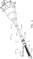
- FIG. 1 illustrates the surgical instrument 1010 that includes an interchangeable shaft assembly 1200 operably coupled to a housing 1012.
- FIG. 2 illustrates the interchangeable shaft assembly 1200 detached from the housing 1012 or handle 1014.
- the handle 1014 may comprise a pair of interconnectable handle housing segments 1016 and 1018 that may be interconnected by screws, snap features, adhesive, etc.
- the handle housing segments 1016, 1018 cooperate to form a pistol grip portion 1019.
- FIGS. 1 and 3 depict a motor-driven surgical cutting and fastening instrument 1010 that may or may not be reused.
- the instrument 1010 includes a previous housing 1012 that comprises a handle 1014 that is configured to be grasped, manipulated and actuated by the clinician.
- the housing 1012 is configured for operable attachment to an interchangeable shaft assembly 1200 that has a surgical end effector 1300 operably coupled thereto that is configured to perform one or more surgical tasks or procedures.
- an interchangeable shaft assembly 1200 that has a surgical end effector 1300 operably coupled thereto that is configured to perform one or more surgical tasks or procedures.
- housing may also encompass a housing or similar portion of a robotic system that houses or otherwise operably supports at least one drive system that is configured to generate and apply at least one control motion which could be used to actuate the interchangeable shaft assemblies disclosed herein and their respective equivalents.
- various components may be “housed” or contained in the housing or various components may be “associated with” a housing. In such instances, the components may not be contained within the housing or supported directly by the housing.
- the term “frame” may refer to a portion of a handheld surgical instrument.
- the term “frame” may also represent a portion of a robotically controlled surgical instrument and/or a portion of the robotic system that may be used to operably control a surgical instrument.
- interchangeable shaft assemblies disclosed herein may be employed with various robotic systems, instruments, components and methods disclosed in U.S. Patent No. 9,072,535 , entitled SURGICAL STAPLING INSTRUMENTS WITH ROTATABLE STAPLE DEPLOYMENT ARRANGEMENTS, that is incorporated by reference herein in its entirety.
- the previous housing 1012 depicted in FIG. 1 is shown in connection with an interchangeable shaft assembly 1200 ( FIGS. 2 , 4 and 5 ) that includes an end effector 1300 that comprises a surgical cutting and fastening device that is configured to operably support a surgical staple cartridge 4000 therein.
- the housing 1012 may be configured for use in connection with interchangeable shaft assemblies that include end effectors that are adapted to support different sizes and types of staple cartridges, have different shaft lengths, sizes, and types, etc.
- the housing 1012 may also be effectively employed with a variety of other interchangeable shaft assemblies including those assemblies that are configured to apply other motions and forms of energy such as, for example, radio frequency (RF) energy, ultrasonic energy and/or motion to end effector arrangements adapted for use in connection with various surgical applications and procedures.
- RF radio frequency
- the end effectors, shaft assemblies, handles, surgical instruments, and/or surgical instrument systems can utilize any suitable fastener that can be gripped and manipulated by the clinician.
- the handle 1014 operably supports a plurality of drive systems therein that are configured to generate and apply various control motions to corresponding portions of the interchangeable shaft assembly that is operably attached thereto.
- the handle 1014 may further include a frame 1020 that operably supports a plurality of drive systems.
- the frame 1020 can operably support a "first" or closure drive system, generally designated as 1030, which may be employed to apply closing and opening motions to the interchangeable shaft assembly 1200 that is operably attached or coupled thereto.
- the closure drive system 1030 may include an actuator in the form of a closure trigger 1032 that is pivotally supported by the frame 1020. More specifically, as illustrated in FIG. 3 , the closure trigger 1032 is pivotally coupled to the handle 1014 by a pin 1033.
- the closure drive system 1030 further includes a closure linkage assembly 1034 that is pivotally coupled to the closure trigger 1032.
- the closure linkage assembly 1034 may include a first closure link 1036 and a second closure link 1038 that are pivotally coupled to the closure trigger 1032 by a pin 1035.
- the second closure link 1038 may also be referred to herein as an "attachment member” and include a transverse attachment pin 1037.
- the first closure link 1036 may have a locking wall or end 1039 thereon that is configured to cooperate with a closure release assembly 1060 that is pivotally coupled to the frame 1020.
- the closure release assembly 1060 may comprise a release button assembly 1062 that has a distally protruding locking pawl 1064 formed thereon.
- the release button assembly 1062 may be pivoted in a counterclockwise direction by a release spring (not shown).
- the closure release assembly 1060 serves to lock the closure trigger 1032 in the fully actuated position.
- the clinician simply pivots the closure release button assembly 1062 such that the locking pawl 1064 is moved out of engagement with the locking wall 1039 on the first closure link 1036.
- the closure trigger 1032 may pivot back to the unactuated position.
- Other closure trigger locking and release arrangements may also be employed.
- An arm 1061 may extend from the closure release button 1062.
- a magnetic element 1063 such as a permanent magnet, for example, may be mounted to the arm 1061.
- the circuit board 1100 can include at least one sensor that is configured to detect the movement of the magnetic element 1063.
- a "Hall Effect" sensor (not shown) can be mounted to the bottom surface of the circuit board 1100.
- the Hall Effect sensor can be configured to detect changes in a magnetic field surrounding the Hall Effect sensor caused by the movement of the magnetic element 1063.
- the Hall Effect sensor can be in signal communication with a microcontroller, for example, which can determine whether the closure release button 1062 is in its first position, which is associated with the unactuated position of the closure trigger 1032 and the open configuration of the end effector, its second position, which is associated with the actuated position of the closure trigger 1032 and the closed configuration of the end effector, and/or any position between the first position and the second position.
- a microcontroller for example, which can determine whether the closure release button 1062 is in its first position, which is associated with the unactuated position of the closure trigger 1032 and the open configuration of the end effector, its second position, which is associated with the actuated position of the closure trigger 1032 and the closed configuration of the end effector, and/or any position between the first position and the second position.
- the handle 1014 and the frame 1020 may operably support another drive system referred to herein as a firing drive system 1080 that is configured to apply firing motions to corresponding portions of the interchangeable shaft assembly attached thereto.
- the firing drive system 1080 may also be referred to herein as a "second drive system”.
- the firing drive system 1080 may employ an electric motor 1082 that is located in the pistol grip portion 1019 of the handle 1014.
- the motor 1082 may be a DC brushed driving motor having a maximum rotation of, approximately, 25,000 RPM, for example.
- the motor may include a brushless motor, a cordless motor, a synchronous motor, a stepper motor, or any other suitable electric motor.
- the motor 1082 may be powered by a power source 1090 that in one form may comprise a removable power pack 1092.
- the power pack 1092 may comprise a proximal housing portion 1094 that is configured for attachment to a distal housing portion 1096.
- the proximal housing portion 1094 and the distal housing portion 1096 are configured to operably support a plurality of batteries 1098 therein.
- Batteries 1098 may each comprise, for example, a Lithium Ion ("LI”) or other suitable battery.
- the distal housing portion 1096 is configured for removable operable attachment to the circuit board 1100 which is also operably coupled to the motor 1082.
- a number of batteries 1098 may be connected in series may be used as the power source for the surgical instrument 1010.
- the power source 1090 may be replaceable and/or rechargeable.
- the electric motor 1082 can include a rotatable shaft (not shown) that operably interfaces with a gear reducer assembly 1084 that is mounted in meshing engagement with a with a set, or rack, of drive teeth 1122 on a longitudinally-movable drive member 1120.
- a voltage polarity provided by the power source 1090 can operate the electric motor 1082 in a clockwise direction wherein the voltage polarity applied to the electric motor by the battery can be reversed in order to operate the electric motor 1082 in a counter-clockwise direction.
- the drive member 1120 will be axially driven in the distal direction "DD".
- the handle 1014 can include a switch which can be configured to reverse the polarity applied to the electric motor 1082 by the power source 1090. As with the other forms described herein, the handle 1014 can also include a sensor that is configured to detect the position of the drive member 1120 and/or the direction in which the drive member 1120 is being moved.
- Actuation of the motor 1082 can be controlled by a firing trigger 1130 that is pivotally supported on the handle 1014.
- the firing trigger 1130 may be pivoted between an unactuated position and an actuated position.
- the firing trigger 1130 may be biased into the unactuated position by a spring 1132 or other biasing arrangement such that when the clinician releases the firing trigger 1130, it may be pivoted or otherwise returned to the unactuated position by the spring 1132 or biasing arrangement.
- the firing trigger 1130 can be positioned "outboard" of the closure trigger 1032 as was discussed above.
- a firing trigger safety button 1134 may be pivotally mounted to the closure trigger 1032 by the pin 1035.
- the safety button 1134 may be positioned between the firing trigger 1130 and the closure trigger 1032 and have a pivot arm 1136 protruding therefrom.
- the safety button 1134 When the closure trigger 1032 is in the unactuated position, the safety button 1134 is contained in the handle 1014 where the clinician cannot readily access it and move it between a safety position preventing actuation of the firing trigger 1130 and a firing position wherein the firing trigger 1130 may be fired. As the clinician depresses the closure trigger 1032, the safety button 1134 and the firing trigger 1130 pivot down wherein they can then be manipulated by the clinician.
- the longitudinally movable drive member 1120 has a rack of teeth 1122 formed thereon for meshing engagement with a corresponding drive gear 1086 of the gear reducer assembly 1084.
- At least one form also includes a manually-actuatable "bailout” assembly 1140 that is configured to enable the clinician to manually retract the longitudinally movable drive member 1120 should the motor 1082 become disabled.
- the bailout assembly 1140 may include a lever or bailout handle assembly 1142 that is configured to be manually pivoted into ratcheting engagement with teeth 1124 also provided in the drive member 1120.
- the clinician can manually retract the drive member 1120 by using the bailout handle assembly 1142 to ratchet the drive member 1120 in the proximal direction "PD".
- Patent No. 8,608,045 entitled POWERED SURGICAL CUTTING AND STAPLING APPARATUS WITH MANUALLY RETRACTABLE FIRING SYSTEM, discloses bailout arrangements and other components, arrangements and systems that may also be employed with the various instruments disclosed herein.
- U.S. Patent No. 8,608,045 is hereby incorporated by reference herein in its entirety.
- the interchangeable shaft assembly 1200 includes a surgical end effector 1300 that comprises an elongate channel 1310 that is configured to operably support a staple cartridge 4000 therein.
- the end effector 1300 may further include an anvil 2000 that is pivotally supported relative to the elongate channel 1310.
- the interchangeable shaft assembly 1200 may further include an articulation joint 3020 and an articulation lock 2140 which can be configured to releasably hold the end effector 1300 in a desired position relative to a shaft axis SA. Examples of various features of at least one form of the end effector 1300, the articulation joint 3020 and articulation locks may be found in U.S. Patent Application Serial No.
- the interchangeable shaft assembly 1200 can further include a proximal housing or nozzle 1201 comprised of nozzle portions 1202 and 1203.
- the interchangeable shaft assembly 1200 can further include a closure system or closure member assembly 3000 which can be utilized to close and/or open the anvil 2000 of the end effector 1300.
- the shaft assembly 1200 can include a spine 1210 that is configured to, one, slidably support a firing member therein and, two, slidably support the closure member assembly 3000 which extends around the spine 1210.
- a distal end 1212 of spine 1210 terminates in an upper lug mount feature 1270 and in a lower lug mount feature 1280.
- the upper lug mount feature 1270 is formed with a lug slot 1272 therein that is adapted to mountingly support an upper mounting link 1274 therein.
- the lower lug mount feature 1280 is formed with a lug slot 1282 therein that is adapted to mountingly support a lower mounting link 1284 therein.
- the upper mounting link 1274 includes a pivot socket 1276 therein that is adapted to rotatably receive therein a pivot pin 1292 that is formed on a channel cap or anvil retainer 1290 that is attached to a proximal end portion 1312 of the elongate channel 1310.
- the lower mounting link 1284 includes lower pivot pin 1286 that adapted to be received within a pivot hole 1314 formed in the proximal end portion 1312 of the elongate channel 1310. See FIG. 5 .
- the lower pivot pin 1286 is vertically aligned with the pivot socket 1276 to define an articulation axis AA about which the surgical end effector 1300 may articulate relative to the shaft axis SA. See FIG. 2 .
- the surgical end effector 1300 is selectively articulatable about the articulation axis AA by an articulation system 2100.
- the articulation system 2100 includes proximal articulation driver 2102 that is pivotally coupled to an articulation link 2120.
- an offset attachment lug 2114 is formed on a distal end 2110 of the proximal articulation driver 2102.
- a pivot hole 2116 is formed in the offset attachment lug 2114 and is configured to pivotally receive therein a proximal link pin 2124 formed on the proximal end 2122 of the articulation link 2120.
- a distal end 2126 of the articulation link 2120 includes a pivot hole 2128 that is configured to pivotally receive therein a channel pin 1317 formed on the proximal end portion 1312 of the elongate channel 1310.
- proximal articulation driver 2102 can be held in position by an articulation lock 2140 when the proximal articulation driver 2102 is not being moved in the proximal or distal directions. Additional details regarding an example of an articulation lock 2140 may be found in U.S. Patent Application Serial No. 15/635,631 , now U.S. Patent Application Publication No. 2019/0000464 , as well as in other references incorporated by reference herein.
- the spine 1210 can comprise a proximal end 1211 which is rotatably supported in a chassis 1240.
- the proximal end 1211 of the spine 1210 has a thread 1214 formed thereon for threaded attachment to a spine bearing 1216 configured to be supported within the chassis 1240. See FIG. 4 .
- Such an arrangement facilitates rotatable attachment of the spine 1210 to the chassis 1240 such that the spine 1210 may be selectively rotated about a shaft axis SA relative to the chassis 1240.
- the interchangeable shaft assembly 1200 includes a closure shuttle 1250 that is slidably supported within the chassis 1240 such that it may be axially moved relative thereto.
- the closure shuttle 1250 includes a pair of proximally-protruding hooks 1252 that are configured for attachment to the attachment pin 1037 ( FIG. 3 ) that is attached to the second closure link 1038 as will be discussed in further detail below.
- the closure member assembly 3000 comprises a proximal closure member segment 3010 that has a proximal end 3012 that is coupled to the closure shuttle 1250 for relative rotation thereto.
- a U shaped connector 1263 is inserted into an annular slot 3014 in the proximal end 3012 of the proximal closure member segment 3010 and is retained within vertical slots 1253 in the closure shuttle 1250.
- Such an arrangement serves to attach the proximal closure member segment 3010 to the closure shuttle 1250 for axial travel therewith while enabling the proximal closure member segment 3010 to rotate relative to the closure shuttle 1250 about the shaft axis SA.
- a closure spring 1268 is journaled on the proximal closure member segment 3010 and serves to bias the proximal closure member segment 3010 in the proximal direction "PD" which can serve to pivot the closure trigger 1032 into the unactuated position when the shaft assembly is operably coupled to the handle 1014.
- the interchangeable shaft assembly 1200 may further include an articulation joint 3020.
- Other interchangeable shaft assemblies may not be capable of articulation.
- a distal closure member or distal closure tube segment 3030 is coupled to the distal end of the proximal closure member segment 3010.
- the articulation joint 3020 includes a double pivot closure sleeve assembly 3022.
- the double pivot closure sleeve assembly 3022 includes an end effector closure tube 3050 having upper and lower distally projecting tangs 3052, 3054.
- An upper double pivot link 3056 includes upwardly projecting distal and proximal pivot pins that engage respectively an upper distal pin hole in the upper proximally projecting tang 3052 and an upper proximal pin hole in an upper distally projecting tang 3032 on the distal closure tube segment 3030.
- a lower double pivot link 3058 includes upwardly projecting distal and proximal pivot pins that engage respectively a lower distal pin hole in the lower proximally projecting tang 3054 and a lower proximal pin hole in the lower distally projecting tang 3034. See FIGS. 4 and 5 .
- the closure member assembly 3000 is translated distally (direction "DD") to close the anvil 2000, for example, in response to the actuation of the closure trigger 1032.
- the anvil 2000 is opened by proximally translating the closure member assembly 3000 which causes the end effector closure sleeve to interact with the anvil 2000 and pivot it to an open position.
- the interchangeable shaft assembly 1200 further includes a firing member 1900 that is supported for axial travel within the spine 1210.
- the firing member 1900 includes an intermediate firing shaft portion 1222 that is configured for attachment to a distal cutting portion or knife bar 1910.
- the intermediate firing shaft portion 1222 may include a longitudinal slot 1223 in the distal end thereof which can be configured to receive a tab 1912 on the proximal end of the distal knife bar 1910.
- the longitudinal slot 1223 and the proximal end tab 1912 can be sized and configured to permit relative movement therebetween and can comprise a slip joint 1914.
- the slip joint 1914 can permit the intermediate firing shaft portion 1222 of the firing member 1900 to be moved to articulate the end effector 1300 without moving, or at least substantially moving, the knife bar 1910.
- the intermediate firing shaft portion 1222 can be advanced distally until a proximal sidewall of the longitudinal slot 1223 comes into contact with the tab 1912 in order to advance the knife bar 1910 and fire the staple cartridge 4000 positioned within the channel 1310.
- the knife bar 1910 includes a knife portion 1920 that includes a blade or tissue cutting edge 1922 and includes an upper anvil engagement tab 1924 and lower channel engagement tabs 1926.
- Various firing member configurations and operations are disclosed in various other references incorporated herein by reference.
- the shaft assembly 1200 further includes a switch drum 1500 that is rotatably received on proximal closure member segment 3010.
- the switch drum 1500 comprises a hollow shaft segment 1502 that has a shaft boss formed thereon for receive an outwardly protruding actuation pin therein.
- the actuation pin extends through a longitudinal slot provided in the lock sleeve to facilitate axial movement of the lock sleeve when it is engaged with the articulation driver.
- a rotary torsion spring 1420 is configured to engage the boss on the switch drum 1500 and a portion of the nozzle housing 1203 to apply a biasing force to the switch drum 1500.
- the switch drum 1500 can further comprise at least partially circumferential openings 1506 defined therein which can be configured to receive circumferential mounts extending from the nozzle portions 1202, 1203 and permit relative rotation, but not translation, between the switch drum 1500 and the nozzle 1201.
- the mounts also extend through openings 3011 in the proximal closure member segment 3010 to be seated in recesses 1219 in the spine 1210. Rotation of the switch drum 1500 about the shaft axis SA will ultimately result in the rotation of the actuation pin and the lock sleeve between its engaged and disengaged positions.
- the rotation of the switch drum 1500 may be linked to the axial advancement of the closure tube or closure member.
- actuation of the closure system may operably engage and disengage the articulation drive system with the firing drive system in the various manners described in further detail in U.S. Patent Application Serial No. 13/803,086 , entitled ARTICULATABLE SURGICAL INSTRUMENT COMPRISING AN ARTICULATION LOCK, now U.S. Patent Application Publication No. 2014/0263541 , and U.S. Patent No. 9,913,642 , entitled SURGICAL INSTRUMENT COMPRISING A SENSOR SYSTEM, the entire disclosures of each being hereby incorporated by reference herein.
- the closure member segment 3010 when the closure tube is in its proximal-most position corresponding to a "jaws open” position, the closure member segment 3010 will have positioned the switch drum 1500 so as to link the articulation system with the firing drive system.
- the closure tube has been moved to its distal position corresponding to a "jaws closed” position, the closure tube has rotated the switch drum 1500 to a position wherein the articulation system is delinked from the firing drive system.
- the shaft assembly 1200 can comprise a slip ring assembly 1600 which can be configured to conduct electrical power to and/or from the end effector 1300 and/or communicate signals to and/or from the end effector 1300, for example.
- the slip ring assembly 1600 can comprise a proximal connector flange 1604 that is mounted to a chassis flange 1242 that extends from the chassis 1240 and a distal connector flange that is positioned within a slot defined in the shaft housings.
- the proximal connector flange 1604 can comprise a first face and the distal connector flange can comprise a second face which is positioned adjacent to and movable relative to the first face.
- the distal connector flange can rotate relative to the proximal connector flange 1604 about the shaft axis SA.
- the proximal connector flange 1604 can comprise a plurality of concentric, or at least substantially concentric, conductors defined in the first face thereof.
- a connector can be mounted on the proximal side of the connector flange and may have a plurality of contacts wherein each contact corresponds to and is in electrical contact with one of the conductors. Such an arrangement permits relative rotation between the proximal connector flange 1604 and the distal connector flange while maintaining electrical contact therebetween.
- the proximal connector flange 1604 can include an electrical connector 1606 which can place the conductors in signal communication with a shaft circuit board 1610 mounted to the shaft chassis 1240, for example.
- a wiring harness comprising a plurality of conductors can extend between the electrical connector 1606 and the shaft circuit board 1610.
- the electrical connector 1606 may extend proximally through a connector opening 1243 defined in the chassis flange 1242. See FIG. 4 . Further details regarding slip ring assembly 1600 may be found in U.S. Patent Application Serial No. 13/803,086 , entitled ARTICULATABLE SURGICAL INSTRUMENT COMPRISING AN ARTICULATION LOCK, now U.S. Patent Application Publication No.
- the shaft assembly 1200 can include a proximal portion which is fixably mounted to the handle 1014 and a distal portion which is rotatable about a longitudinal axis.
- the rotatable distal shaft portion can be rotated relative to the proximal portion about the slip ring assembly 1600, as discussed above.
- the distal connector flange of the slip ring assembly 1600 can be positioned within the rotatable distal shaft portion.
- the switch drum 1500 can also be positioned within the rotatable distal shaft portion. When the rotatable distal shaft portion is rotated, the distal connector flange and the switch drum 1500 can be rotated synchronously with one another.
- the switch drum 1500 can be rotated between a first position and a second position relative to the distal connector flange.
- the articulation drive system When the switch drum 1500 is in its first position, the articulation drive system may be operably disengaged from the firing drive system and, thus, the operation of the firing drive system may not articulate the end effector 1300 of the shaft assembly 1200.
- the switch drum 1500 When the switch drum 1500 is in its second position, the articulation drive system may be operably engaged with the firing drive system and, thus, the operation of the firing drive system may articulate the end effector 1300 of the shaft assembly 1200.
- the switch drum 1500 When the switch drum 1500 is moved between its first position and its second position, the switch drum 1500 is moved relative to distal connector flange.
- the shaft assembly 1200 can comprise at least one sensor configured to detect the position of the switch drum 1500.
- the chassis 1240 includes at least one, and preferably two, tapered attachment portions 1244 formed thereon that are adapted to be received within corresponding dovetail slots 1702 formed within a distal attachment flange portion 1700 of the frame 1020. See FIG. 3 .
- Each dovetail slot 1702 may be tapered or, stated another way, be somewhat V-shaped to seatingly receive the attachment portions 1244 therein.
- a shaft attachment lug 1226 is formed on the proximal end of the intermediate firing shaft portion 1222.
- the shaft attachment lug 1226 is received in a firing shaft attachment cradle 1126 formed in a distal end 1125 of the longitudinal drive member 1120. See FIG. 3 .
- the latch system 1710 includes a lock member or lock yoke 1712 that is movably coupled to the chassis 1240.
- the lock yoke 1712 has a U-shape with two spaced downwardly extending legs 1714.
- the legs 1714 each have a pivot lug 1715 formed thereon that are adapted to be received in corresponding holes 1245 formed in the chassis 1240.
- Such arrangement facilitates pivotal attachment of the lock yoke 1712 to the chassis 1240.
- the lock yoke 1712 may include two proximally protruding lock lugs 1716 that are configured for releasable engagement with corresponding lock detents or grooves 1704 in the distal attachment flange portion 1700 of the frame 1020. See FIG. 3 .
- the lock yoke 1712 is biased in the proximal direction by spring or biasing member (not shown). Actuation of the lock yoke 1712 may be accomplished by a latch button 1722 that is slidably mounted on a latch actuator assembly 1720 that is mounted to the chassis 1240.
- the latch button 1722 may be biased in a proximal direction relative to the lock yoke 1712.
- the lock yoke 1712 may be moved to an unlocked position by biasing the latch button in the distal direction which also causes the lock yoke 1712 to pivot out of retaining engagement with the distal attachment flange portion 1700 of the frame 1020.
- the lock lugs 1716 are retainingly seated within the corresponding lock detents or grooves 1704 in the distal attachment flange portion 1700.
- an interchangeable shaft assembly that includes an end effector of the type described herein that is adapted to cut and fasten tissue, as well as other types of end effectors
- the clinician may actuate the closure trigger 1032 to grasp and manipulate the target tissue into a desired position. Once the target tissue is positioned within the end effector 1300 in a desired orientation, the clinician may then fully actuate the closure trigger 1032 to close the anvil 2000 and clamp the target tissue in position for cutting and stapling. In that instance, the first drive system 1030 has been fully actuated.
- One form of the latch system 1710 is configured to prevent such inadvertent detachment.
- the lock yoke 1712 includes at least one and preferably two lock hooks 1718 that are adapted to contact corresponding lock lug portions 1256 that are formed on the closure shuttle 1250.
- the lock yoke 1712 may be pivoted in a distal direction to unlock the interchangeable shaft assembly 1200 from the housing 1012.
- the lock hooks 1718 do not contact the lock lug portions 1256 on the closure shuttle 1250.
- the lock yoke 1712 is prevented from being pivoted to an unlocked position.
- the clinician were to attempt to pivot the lock yoke 1712 to an unlocked position or, for example, the lock yoke 1712 was inadvertently bumped or contacted in a manner that might otherwise cause it to pivot distally, the lock hooks 1718 on the lock yoke 1712 will contact the lock lug portions 1256 on the closure shuttle 1250 and prevent movement of the lock yoke 1712 to an unlocked position.
- the clinician may position the chassis 1240 of the interchangeable shaft assembly 1200 above or adjacent to the distal attachment flange 1700 of the frame 1020 such that the tapered attachment portions 1244 formed on the chassis 1240 are aligned with the dovetail slots 1702 in the frame 1020.
- the clinician may then move the shaft assembly 1200 along an installation axis that is perpendicular to the shaft axis SA to seat the attachment portions 1244 in "operable engagement" with the corresponding dovetail receiving slots 1702.
- the shaft attachment lug 1226 on the intermediate firing shaft portion 1222 will also be seated in the cradle 1126 in the longitudinally movable drive member 1120 and the portions of the pin 1037 on the second closure link 1038 will be seated in the corresponding hooks 1252 in the closure shuttle 1250.
- operble engagement in the context of two components means that the two components are sufficiently engaged with each other so that upon application of an actuation motion thereto, the components may carry out their intended action, function and/or procedure.
- At least five systems of the interchangeable shaft assembly 1200 can be operably coupled with at least five corresponding systems of the handle 1014.
- a first system can comprise a frame system which couples and/or aligns the frame or spine of the shaft assembly 1200 with the frame 1020 of the handle 1014.
- Another system can comprise a closure drive system 1030 which can operably connect the closure trigger 1032 of the handle 1014 and the closure tube 1260 and the anvil 2000 of the shaft assembly 1200.
- the closure shuttle 1250 of the shaft assembly 1200 can be engaged with the pin 1037 on the second closure link 1038.
- Another system can comprise the firing drive system 1080 which can operably connect the firing trigger 1130 of the handle 1014 with the intermediate firing shaft portion 1222 of the shaft assembly 1200.
- the shaft attachment lug 1226 can be operably connected with the cradle 1126 of the longitudinal drive member 1120.
- Another system can comprise an electrical system which can signal to a controller in the handle 1014, such as microcontroller, for example, that a shaft assembly, such as shaft assembly 1200, for example, has been operably engaged with the handle 1014 and/or, two, conduct power and/or communication signals between the shaft assembly 1200 and the handle 1014.
- the shaft assembly 1200 can include an electrical connector 1810 that is operably mounted to the shaft circuit board 1610.
- the electrical connector 1810 is configured for mating engagement with a corresponding electrical connector 1800 on the handle control board 1100. Further details regaining the circuitry and control systems may be found in U.S. Patent Application Serial No.
- the fifth system may consist of the latching system for releasably locking the shaft assembly 1200 to the handle 1014.
- the anvil 2000 in the illustrated example includes an anvil body 2002 that terminates in an anvil mounting portion 2010.
- the anvil mounting portion 2010 is movably or pivotably supported on the elongate channel 1310 for selective pivotal travel relative thereto about a fixed anvil pivot axis PA that is transverse to the shaft axis SA.
- a pivot member or anvil trunnion 2012 extends laterally out of each lateral side of the anvil mounting portion 2010 to be received in a corresponding trunnion cradle 1316 formed in the upstanding walls 1315 of the proximal end portion 1312 of the elongate channel 1310.
- the anvil trunnions 2012 are pivotally retained in their corresponding trunnion cradle 1316 by the channel cap or anvil retainer 1290.
- the channel cap or anvil retainer 1290 includes a pair of attachment lugs that are configured to be retainingly received within corresponding lug grooves or notches formed in the upstanding walls 1315 of the proximal end portion 1312 of the elongate channel 1310. See FIG. 5 .
- the distal closure member or end effector closure tube 3050 employs two axially offset, proximal and distal positive jaw opening features 3060 and 3062.
- the positive jaw opening features 3060, 3062 are configured to interact with corresponding relieved areas and stepped portions formed on the anvil mounting portion 2010 as described in further detail in U.S. Patent Application Serial No. 15/635,631 , entitled SURGICAL INSTRUMENT WITH AXIALLY MOVABLE CLOSURE MEMBER, now U.S. Patent Application Publication No. 2019/0000464 , the entire disclosure which has been herein incorporated by reference.
- Other jaw opening arrangements may be employed.
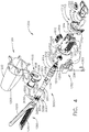
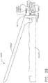
- FIGS. 6-8 depict a previous surgical cutting and fastening instrument 5010 that is configured to generate rotary drive motions for operating a surgical end effector 5012.
- the endoscopic surgical instrument 5010 comprises a handle 5006, a shaft 5008, and an articulating surgical end effector 5012 pivotally connected to the shaft 5008 at an articulation pivot 5014.
- An articulation control 5016 may be provided adjacent to the handle 5006 to effect rotation of the end effector 5012 about the articulation pivot 5014. It will be appreciated that various embodiments may include a non-pivoting end effector, and therefore may not have an articulation pivot 5014 or articulation control 5016.
- the handle 5006 of the instrument 5010 may include a closure trigger 5018 and a firing trigger 5020 for actuating the end effector 5012. It will be appreciated that instruments having end effectors directed to different surgical tasks may have different numbers or types of triggers or other suitable controls for operating the end effector 5012.
- a clinician or operator of the instrument 5010 may articulate the end effector 5012 relative to the shaft 5008 by utilizing the articulation control 5016, as described in more detail in pending U.S. Patent No. 7,670,334 , entitled SURGICAL INSTRUMENT HAVING AN ARTICULATING END EFFECTOR, the entire disclosure of which is incorporated herein by reference.
- the end effector 5012 includes in this example, among other things, a staple channel 5022 and a pivotally translatable clamping member, such as an anvil 5024, which are maintained at a spacing that assures effective stapling and severing of tissue clamped in the end effector 5012.
- the handle 5006 includes a pistol grip 5026 toward which the closure trigger 5018 is pivotally drawn by the clinician to cause clamping or closing of the anvil 5024 towards the staple channel 5022 of the end effector 5012 to thereby clamp tissue positioned between the anvil 5024 and channel 5022.
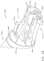
- the end effector 5012 includes, in addition to the previously-mentioned channel 5022 and anvil 5024, a cutting instrument 5032, a sled 5033, a staple cartridge 5034 that is removably seated in the channel 5022, and a helical screw shaft 5036.
- the cutting instrument 5032 may be, for example, a knife.
- the anvil 5024 includes pivot pins 5025 that are movably supported in corresponding slots in the channel 5022.
- the anvil 5024 includes a tab 5027 at its proximate end that is inserted into a component of the mechanical closure system (described further below) to open and close the anvil 5024.
- the shaft 5008 includes a proximal closure tube 5040 and a distal closure tube 5042 pivotably linked by a pivot link 5044.
- the distal closure tube 5042 includes an opening 5045 into which the tab 5027 on the anvil 5024 is inserted in order to open and close the anvil 5024, as further described below.
- Disposed inside the closure tubes 5040, 5042 may be a proximate spine tube 5046.
- Disposed inside the proximate spine tube 5046 may be a main rotational (or proximate) drive shaft 5048 that communicates with a secondary (or distal) drive shaft 5050 via a bevel gear assembly 5052a-c.
- the secondary drive shaft 5050 is connected to a drive gear 5054 that engages a proximate drive gear 5056 of the helical screw shaft 5036.
- the vertical bevel gear 5052b may sit and pivot in an opening 5057 in the distal end of the proximate spine tube 5046.
- a distal spine tube 5058 may be used to enclose the secondary drive shaft 5050 and the drive gears 5054, 5056.
- a bearing 5038 positioned at a distal end of the staple channel 5022, receives the helical screw shaft 5036, allowing the helical screw shaft 5036 to freely rotate with respect to the channel 5022.
- the helical screw shaft 5036 may interface a threaded opening (not shown) of the knife 5032 such that rotation of the helical screw shaft 5036 causes the knife 5032 to translate distally or proximately (depending on the direction of the rotation) through the staple channel 5022.
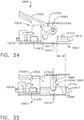
- the handle 5006 includes exterior lower side pieces 5059, 5060 and nozzle pieces 5061, 5062 that fit together to form, in general, the exterior of the handle 5006.
- a battery 5064 such as a Li ion battery, may be provided in the pistol grip portion 5026 of the handle 5006.
- the battery 5064 powers a motor 5065 disposed in an upper portion of the pistol grip portion 5026 of the handle 5006.
- the motor 5065 may drive a 90° bevel gear assembly 5066 comprising a first bevel gear 5068 and a second bevel gear 5070.
- the bevel gear assembly 5066 may drive a planetary gear assembly 5072.
- the planetary gear assembly 5072 may include a pinion gear 5074 connected to a drive shaft 5076.
- the pinion gear 5074 may drive a mating ring gear 5078 that drives a helical gear drum 5080 via a drive shaft.
- a ring 5084 may be threaded on the helical gear drum 5080.
- the handle 5006 may include a middle handle piece 5104 adjacent to the upper portion of the firing trigger 5020.
- the handle 5006 also may comprise a bias spring 5112 connected between posts on the middle handle piece 5104 and the firing trigger 5020.
- the bias spring 5112 may bias the firing trigger 5020 to its fully open position. In that way, when the operator releases the firing trigger 5020, the bias spring 5112 will pull the firing trigger 5020 to its open position.
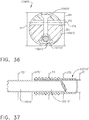
- the distal end of the helical gear drum 5080 includes a distal drive shaft 5120 that drives a ring gear 5122, which mates with a pinion gear 5124.
- the pinion gear 5124 is connected to the main drive shaft 5048 of the main drive shaft assembly.
- the ring 5084 threaded on the helical gear drum 5080 may include a post 5086 that is disposed within a slot 5088 of a slotted arm 5090.
- the slotted arm 5090 has an opening 5092 in its opposite end 5094 that receives a pivot pin 5096 that is connected between the handle exterior side pieces 5059, 5060.
- the pivot pin 5096 is also disposed through an opening 5100 in the firing trigger 5020 and an opening 5102 in the middle handle piece 5104.
- the middle handle piece 5104 includes a backside shoulder 5106 that engages the slotted arm 5090.
- the middle handle piece 5104 also has a forward motion 5107 stop that engages the firing trigger 5020.
- the movement of the slotted arm 5090 is controlled by rotation of the motor 5065.
- the middle handle piece 5104 will be free to rotate counter clockwise.
- the firing trigger 5020 will engage the forward motion stop 5107 of the middle handle piece 5104, causing the middle handle piece 5104 to rotate counter clockwise.
- the middle handle piece 5104 will only be able to rotate counter clockwise as far as the slotted arm 5090 permits. In that way, if the motor 5065 should stop rotating for some reason, the slotted arm 5090 will stop rotating, and the user will not be able to further draw in the firing trigger 5020 because the middle handle piece 5104 will not be free to rotate counter clockwise due to the slotted arm 5090.
- the closure system includes a yoke 5250 connected to the closure trigger 5018.
- a pivot pin 5252 is inserted through aligned openings in both the closure trigger 5018 and the yoke 5250 such that they both rotate about the same point.
- the distal end of the yoke 5250 is connected, via a pin 5254, to a first closure bracket 5256.
- the first closure bracket 5256 connects to a second closure bracket 5258.
- the instrument 5010 also includes a closure drive shaft 5260 disposed inside the proximal closure tube 5040.
- the closure drive shaft 5260 may include a window 5261 into which a post 5263 on one of the handle exterior pieces, such as exterior lower side piece 5059 in the illustrated embodiment, is disposed to fixedly connect the closure drive shaft 5260 to the handle 5006. In that way, the proximal closure tube 5040 is capable of moving longitudinally relative to the closure drive shaft 5260.
- the closure drive shaft 5260 may also include a distal collar 5267 that fits into a cavity in proximate spine tube 5046 and is retained therein by a cap.
- the closure brackets 5256, 5258 cause the proximal closure tube 5040 to move distally (i.e., away from the handle end of the instrument 5010), which causes the distal closure tube 5042 to move distally, which causes the anvil 5024 to rotate about the pivot pins 5025 into the clamped or closed position.
- the proximal closure tube 5040 is caused to slide proximately, which causes the distal closure tube 5042 to slide proximately, which, by virtue of the tab 5027 being inserted in the opening 5045 of the distal closure tube 5042, causes the anvil 5024 to pivot about the pivot pins 5025 into the open or unclamped position.
- an operator may clamp tissue between the anvil 5024 and channel 5022, and may unclamp the tissue following the cutting/stapling operation by unlocking the closure trigger 5018 from the locked position.
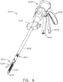
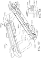
- the instrument 10010 includes a housing 10012 that comprises a handle 10014 that is configured to be grasped, manipulated and actuated by the clinician.
- the instrument 10010 includes a shaft assembly 10200 that has a surgical end effector 10300 operably coupled thereto that is configured to perform one or more surgical tasks or procedures.
- the shaft assembly 10200 comprises an interchangeable shaft assembly that is intended to be removably couplable to the handle assembly 10014 in the various manners disclosed herein.
- the shaft assembly 10200 may also comprise a dedicated shaft assembly that is not intended to be removed from the handle 10014. Only those specific components necessary to understand the functions and operation of the shaft assembly 10200 will be discussed in further detail below.
- the surgical end effector 10300 comprises an elongate channel 10310 that is configured to operably support a staple cartridge 10400 therein.
- the end effector 10300 also includes an anvil 10500 that is pivotally supported relative to the elongate channel 10310.
- the anvil 10500 may be fabricated using various fabricating techniques described in U.S. Patent Application Serial No. 16/105,101 , entitled METHOD FOR FABRICATING SURGICAL STAPLER ANVILS, the entire disclosure of which is hereby incorporated by reference herein.
- the shaft assembly 10200 may further include an articulation joint 10250 that facilitates articulation of the surgical end effector 10300 about an articulation axis AA that is transverse to a longitudinal shaft axis LA.
- Other shaft assemblies may not be capable of articulation.
- the shaft assembly 10200 comprises a proximal outer shaft tube or member 10210 that extends distally from a nozzle assembly 10202.
- a proximal end 10312 of the elongate channel comprises a tubular portion 10314 that is similar in size to the proximal outer shaft tube 10120 and is coupled to the distal end of the proximal outer shaft tube 10210 to form the articulation joint 10250.
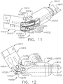
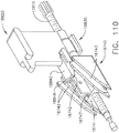
- the articulation joint 10250 includes a double pivot shaft assembly 10252. See FIGS. 11 and 12 .
- the tubular portion 10314 of the elongate channel 10310 includes upper and lower proximally projecting tangs 10316, 10318. See FIG. 11 .
- An upper double pivot link 10320 includes upwardly projecting distal and proximal pivot pins that engage respectively an upper pin hole in the upper proximally projecting tang 10316 and an upper distal pin hole in an upper distally projecting tang 10212 on the proximal outer shaft tube 10210.
- a lower double pivot link 10322 includes downwardly projecting distal and proximal pivot pins that engage respectively a lower distal pin hole in the lower proximally projecting tang 10318 and a lower proximal pin hole in a lower distally projecting tang 10214 in the proximal outer shaft tube 10210. See FIG. 11 .
- the shaft assembly 10200 also includes an internal spine member 10230 that is pivotally coupled to an insert assembly 10330 that is received within the tubular portion 10314 of the elongate channel 10310 and is attached thereto by, for example, welding, adhesive, fasteners, etc.
- a proximal end of the internal spine member 10230 may be rotatably coupled to a chassis (not shown) within the nozzle assembly 10202 in the various manners disclosed herein, for example.
- the distal end of the internal spine member 10230 may be pinned to the insert assembly 10330 to facilitate pivotal travel of the elongate channel 10310 relative to the internal spine member 10230.
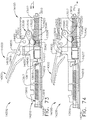
- the surgical end effector 10300 is selectively articulatable about the articulation axis AA by an articulation system 10260.
- the articulation system 10260 includes an articulation motor 10262 that is operably supported in the nozzle assembly 10202, for example. See FIG. 10 .
- the articulation motor 10262 may be operably supported in the housing 10012 or handle 10014 or other portion of a robotic system. Referring to FIG. 10 , the articulation motor 10262 is coupled to an articulation drive gear 10264 that is in meshing engagement with a drive gear rack 10266 that is attached to or otherwise formed in a proximal articulation driver 10268.
- a distal end of the proximal articulation driver 10268 is pivotally coupled to a distal articulation link 10270.
- an offset attachment lug 10272 is formed on a distal end 10271 of the proximal articulation driver 10268.
- a pivot hole is formed in the offset attachment lug 10272 and is configured to pivotally receive therein a proximal link pin 10276 formed on the proximal end 10274 of the distal articulation link 10270.
- a distal end 10278 of the distal articulation link 10270 includes a pivot hole that is configured to pivotally receive therein a channel pin 10332 formed on the insert assembly 10330.
- Operation of the articulation motor 10262 will cause axial movement of the proximal articulation driver 10268.
- Axial movement of proximal articulation driver 10268 will apply articulation motions to the elongate channel 10310 to thereby cause the surgical end effector 10300 to articulate about the articulation axis AA relative to the internal spine member 10230.
- Other articulation systems and arrangements may be employed in the various manners disclosed herein. In other embodiments, the surgical end effector may not be articulatable.
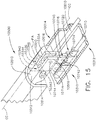
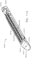
- the surgical end effector 10300 includes a firing member that is axially movable within the surgical end effector 10300 between a starting position and an ending position.
- the firing member may be configured to sever tissue that is clamped between the anvil 10500 and a surgical staple cartridge 10400 that is operably supported in the elongate channel 10310.
- the staple cartridge 10400 includes lines of surgical staples or fasteners that are operably supported on corresponding drivers that are movably supported in the cartridge.
- the firing member As the firing member is driven distally, the firing member cooperates with a sled or camming assembly that is supported in the staple cartridge that serves to advance the drivers in a direction toward the closed anvil which causes the staples or fasteners supported thereon to pierce through the clamped tissue into forming contact with the underside of the closed anvil.
- a sled or camming assembly that is supported in the staple cartridge that serves to advance the drivers in a direction toward the closed anvil which causes the staples or fasteners supported thereon to pierce through the clamped tissue into forming contact with the underside of the closed anvil.
- the surgical instrument 10010 also employs a firing system 10600 that is configured to apply rotary drive motions to the firing member to drive the firing member between the starting and end positions.
- the firing system 10600 includes a firing motor 10602 that is operably supported in the nozzle assembly 10202, for example.
- the firing motor 10602 may be operably supported in the housing or handle or other portion of a robotic system.
- the firing motor 10602 is coupled to a firing drive gear 10604 that is in meshing engagement with a driven gear 10606 that is attached to or otherwise formed in rotary firing drive shaft 10610.
- the firing drive shaft 10610 may be flexible to permit articulation of the surgical end effector 10300 in the manner described above.
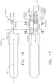
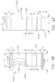
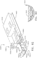
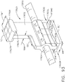
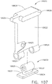
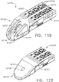
- FIG. 13 depicts one example of a rotary driven firing member 10620 that may be employed in the surgical end effector 10300.
- the firing member 10620 comprises a body portion 10622 that includes two downwardly extending hollow mounting portions 10624 that are unthreaded and spaced from each other to receive a threaded drive nut 10630 therebetween.
- the threaded drive nut 10630 is threaded onto a threaded portion 10612 of the rotary firing drive shaft 10610.
- a distal end 10614 of the rotary firing drive shaft 10610 may be configured to be rotatably supported in a bearing (not shown) that is housed within the elongate channel and is configured to rotatably support the rotary firing drive shaft 10610 therein.
- the drive nut 10630 includes a vertical tab portion 10632 that is sized to extend through an axial slot in the bottom of the elongate channel.
- Two laterally extending channel engagement flanges 10634 are formed on the threaded drive nut 10630 and are configured to engage the bottom of the elongate channel.
- two laterally extending anvil engagement tabs 10626 are formed on the top of the firing member body 10622 and are configured to engage corresponding ledges formed in the anvil 10500 as the firing member 10620 is axially moved within the end effector 10300.
- the firing member 10620 includes a camming sled engagement feature 10628 that is configured to operably engage a camming assembly that is movably stored in the staple cartridge.
- the camming sled or camming assembly may include a tissue cutting member or a tissue cutting feature attached to the firing member 10620.
- the firing member 10620 may be stored within an unfired staple cartridge and is configured to be seated on the threaded drive nut 10630 when the cartridge is operably installed within the elongate channel.
- a variety of other rotary driven firing member arrangements may also be employed.
- firing and tissue cutting members that are permanently threaded onto the rotary firing drive shaft may also be employed.
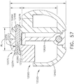
- the firing member 10620 may serve to maintain a desired amount of tissue gap between a deck surface 10402 on the staple cartridge 10400 and a staple forming undersurface 10502 on the anvil 10500. See FIG. 9 .
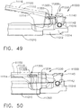
- the surgical instrument 10010 also includes a rotary driven closure system 10700 that is configured to apply rotary closure motions to the anvil 10500.
- the rotary driven closure system 10700 comprises a closure motor 10702 that is operably supported in the nozzle assembly 10202, for example.
- the closure motor 10702 may be operably supported in the housing or handle or other portion of a robotic system.
- the closure motor 10702 is coupled to a closure drive gear 10704 that is in meshing engagement with a driven gear 10706 that is attached to or otherwise formed in rotary closure drive shaft 10710.
- the closure drive shaft 10710 may be flexible to permit articulation of the surgical end effector 10300 in the manner described above.
- the surgical end effector 10300 includes the anvil 10500 that includes a proximally-extending mounting tab 10510 that is configured to be pivotally attached to a distal insert portion 10334 of the insert assembly 10330.
- the distal insert portion 10334 may be separate from the insert assembly 10330 and otherwise be attached to the proximal end portion 10312 of the elongate channel 10310 by welding, adhesive, fasteners, etc.
- the distal insert portion 10334 may actually comprise a portion of the elongate channel 10310 and be integrally formed therewith.
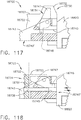
- the anvil mounting tab 10510 includes a distal portion 10512 through which a transverse slot 10514 extends therethrough and is aligned with a transverse slot 10336 in the distal insert portion 10334 as well as a slot 10315 in the tubular portion 10314 of the elongate channel 10310. See FIG. 18 .
- the anvil mounting tab 10510 is pivotally attached to the elongate channel 10310 by a rivet 10340.
- the anvil mounting tab 10510, as well as the distal insert portion 10334, are sufficiently robust to provide a sufficient amount of strength where the rivet 10340 operates which provides the ability to locate the pivoting attachment point above the centerline or midpoint of the end effector and thereby afford sufficient room therein for the firing member components and rotary drive components.
- Orbit forming of the rivet 10340 pivotally cinches the anvil mounting tab 10510 to the elongate channel 10310 and can remove excessive play or movement (tolerance slop) which serves to place the rivet 10340 in complete or significantly complete shear for resistance against closure loads.
- the relatively broad contact between such components may also serve to prevent or minimize twisting between the anvil mounting tab 10510 and the elongate channel 10310.
- the anvil 10500 is asymmetrically coupled to the elongate channel 10310. Stated another way, the location in which the anvil 10500 is attached to the elongate channel 10310 is laterally offset from the end effector centerline EC.
- the rivet 10340 comprises solid core rivet with a diameter of 0.05" - 0.1" and an orbit formed head 10342 on one end of the rivet shank 10344 and a machined head 10346 on the other end of the rivet shank 10344.
- the riveting is done in such a way that the rivet 10340 would hold a final formed height that would ensure intimate contact between the anvil mounting tab 10510 and the corresponding attachment portions of the elongate channel 10310.
- the "orbit formed" head 10342 would swell the rivet shank 10344 on that side of the anvil mounting tab 10510 and elongate channel portions which may prevent the rivet from rotating relative to that part while the other "pre-machined" side 10346 would not have a swelled shank portion which may permit the adjacent components to rotate.
- the rivet 10340 is fixed relative to the channel portion to avoid a condition wherein the anvil pivots freely relative to the insert and elongate channel.
- closure system 10700 that is configured to apply opening and closure motions to the anvil 10500.
- closure system 10700 comprises a closure linkage assembly 10716 that is pivotally coupled to the anvil mounting tab 10510 for pivotal travel relative thereto about a common closure axis CA.
- the closure drive shaft 10710 comprises a threaded drive segment 10714 that is configured to threadably engage a drive nut 10730 that is supported by a drive yoke 10720.
- the drive yoke 10720 includes two yoke arms 10722 that have unthreaded holes 10724 therethrough to permit the closure drive shaft 10710 to pass therethrough.
- the drive nut 10730 has a threaded hole 10732 therethrough that is threaded onto the threaded drive segment 10714 of the closure drive shaft 10710 and is received between the yoke arms 10722.
- a closure link 10740 is pivotally coupled to the drive yoke 10720 by a pin 10742.
- the closure link 10740 is also pivotally attached (pinned) to the anvil mounting tab 10510 by a pin 10744. See FIG. 19 .
- a spacer member 10746 is provided to fill the space between the closure link 10740 and spaced arms 10516 of the anvil mounting tab 10510.
- the closure link may be sized and shaped to fill in that space.
- a retainer tab 10311 is formed in the elongate channel 10310 to define an axial trough 10313 for slidably receiving the drive yoke 10720 therein.
- Rotation of the rotary closure drive shaft 10710 in a first rotary direction will cause the drive yoke 10720 to move distally and cause the closure link 10740 to pull the anvil mounting tab 10510 in an opening direction which causes the anvil 10500 to pivot to an open position about the pivot axis PA.
- the rotary driven closure system 10700 may be actuated during the actuation of the rotary driven firing system 10600 such that the closure system 10700 continues to apply additional closure motions to the anvil as the firing member is axially driven through the staple cartridge.
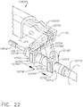
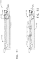
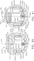
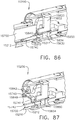
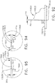
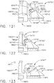
- FIGS. 22 and 23 illustrate an alternate closure drive arrangement wherein the anvil mounting tab 10510' of the anvil 10500' is generally centrally supported within the end effector.
- the anvil mounting portion 10510' may be pivotally coupled to the elongate channel 10310' in the manner described above.
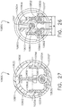
- the rotary closure drive shaft 10710' is hollow and concentrically supports the rotary firing shaft 10610' therein.
- the rotary closure drive shaft 10710' and the rotary firing drive shaft 10610' are centrally disposed within the elongate channel 10310' as can be seen in FIG. 23 .
- the rotary firing drive shaft 10610' rotatably extends through the rotary closure drive shaft 10710' and includes a distal threaded portion 10612' that is configured to threadably drive the firing member 10620 in the manner described above, for example.
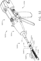
- FIGS. 22 and 23 employs a rotary actuated closure linkage assembly 10716' that is configured to apply opening and closure motions to the anvil 10500'.
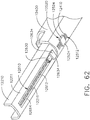
- the closure linkage assembly 10716' comprises a proximal drive yoke assembly 10720' and a distal drive yoke assembly 10750.
- the proximal drive yoke assembly 10720' includes two spaced yoke arms 10722' that have unthreaded holes 10724' therethrough to permit the closure drive shaft 10710' to pass therethrough.
- a proximal drive nut 10730' is received between the spaced yoke arms 10722' and includes a threaded hole for threadably engaging a proximal thread segment 10712' on the rotary closure drive shaft 10710'.
- the proximal drive yoke assembly 10720' is pivotally coupled to a proximal closure link 10740' that is pivotally pinned to the anvil mounting portion 10510'.
- the distal drive yoke assembly 10750 includes two spaced yoke arms 10752 that have unthreaded holes 10754 therethrough to permit the closure drive shaft 10710' to pass therethrough.
- a distal drive nut 10760 is received between the spaced yoke arms 10752 and includes a threaded hole for threadably engaging a distal thread segment 10714' on the rotary closure drive shaft 10710'.
- the proximal threaded segment 10712' and the distal threaded segment 10714' are thread in opposite directions.
- the distal drive yoke assembly 10750 is pivotally coupled to a U-shaped distal closure link 10770 that is pivotally pinned to the anvil mounting portion 10510'.
- the U-shaped distal closure link 10770 affords the closure linkage assembly 10716' with a symmetric load bearing arrangement.
- Rotation of the rotary closure drive shaft 10710' in a first rotary direction will cause the proximal drive yoke 10720' and the distal drive yoke assembly 10750 to axially move away from each other to pull the anvil mounting tab 10510' in an opening direction causing the anvil 10500' to pivot to an open position about the pivot axis PA.
- rotation of the rotary closure drive shaft 10710' in a second rotary direction will cause the proximal drive yoke 10720' and distal drive yoke assembly 10750 to move towards each other and push the anvil mounting tab 10510' in a closing direction causing the anvil 10500' to pivot to a closed position about the pivot axis PA.
- Such arrangement may serve to apply generally higher closure forces to the anvil 10500'.
- the rotary firing drive shaft 10610' is independently rotatable relative to the rotary closure drive shaft 10710'.
- the rotary driven closure system 10700 may be actuated during the actuation of the rotary driven firing system 10600 such that the closure system 10700 continues to apply additional closure motions to the anvil as the firing member is axially driven through the staple cartridge.
- FIGS. 24-27 illustrate an another surgical end effector 10800 that employs a closure drive arrangement wherein an anvil mounting tab 10804 of an anvil 10802 is centrally supported within the end effector 10800 and two rotary closure shafts 10830 and 10840 are employed to apply closure motions to the anvil 10802.
- a distal portion 10806 of the anvil mounting tab 10804 includes a pair of laterally extending pivot members 10808 that are adapted to be pivotally cradled in pivot cradles 10356 in upstanding walls 10354 of a distal mounting portion of the elongate channel 10310". See FIG. 27 .
- the pivot members 10808 are vertically movable or "floatable" within their corresponding pivot cradles 10356.
- the rotary firing drive shaft 10610 ( FIG. 26 ) is vertically supported above the rotary closure drive shaft 10710 ( FIGS. 24 and 25 ).
- the rotary firing drive shaft 10610 includes a firing drive gear 10611 that is configured to drivingly engage a driven gear (not shown) on a distal firing drive shaft 10613 that is rotatably supported in the elongate channel 10310" in the various manners described herein. See FIG. 27 .
- a firing member drive nut 10630 is threaded on the distal firing drive shaft 10613 and serves to drive a firing member 10620 within the end effector 10800 as the rotary firing drive shaft 10610 is rotated in the manner described herein.
- the rotary closure drive shaft 10710 includes a closure drive gear 10715 that is centrally disposed between a right distal closure shaft 10830 and a left distal closure shaft 10840.
- the right distal closure shaft 10830 includes a right driven gear 10832 that is in meshing engagement with the closure drive gear 10715 and the left distal closure shaft 10840 includes a left driven gear 10842 that is also in meshing engagement with the closure drive gear 10715.
- Rotation of the rotary closure drive shaft 10710 will result in the rotation of the right distal closure shaft 10830 in a first rotary direction and the rotation of the left distal closure shaft 10840 in a second rotary direction.
- FIGS. 24-26 employs a rotary actuated right closure linkage assembly 10850 and a rotary actuated left closure linkage assembly 10860 that are configured to apply opening and closure motions to the anvil 10802.
- the right closure linkage assembly 10850 comprises a proximal drive nut assembly 10852 that is threaded onto the right distal closure shaft 10830 and is coupled to a right closure link 10854 that is attached to the anvil mounting tab 10804.
- the left closure linkage assembly 10860 comprises a left drive nut assembly 10862 that is threaded onto the left distal closure shaft 10840 and is coupled to a left closure link 10864 that is attached to the anvil mounting tab 10804.
- the diameter D of the right distal closure shaft 10830 and the left distal closure shaft 10840 may be approximately 0.078". See FIG. 26 .
- the space "E” between the right drive nut assembly 10852 and the left drive nut assembly 10862 may be approximately 0.093" and the width "W" of the channel 10310" may be approximately 0.256".
- Rotation of the rotary closure drive shaft 10710 in a first rotary direction will cause the right drive nut assembly 10852 and the left drive nut assembly 10862 to move in a synchronized fashion to open the anvil 10802 in a balanced uniform manner.
- Rotation of the rotary closure drive shaft 10710 in a second rotary direction will cause the right drive nut assembly 10852 and the left drive nut assembly 10862 to move in a synchronized fashion to close the anvil 10802 in a balanced uniform manner and reduce any twisting moment on the anvil 10802 as the anvil 10802 is pivoted closed.
- the anvil mounting tab 10804 includes a domed or spherical distal surface portion 10809.
- a closure ring 10811 ( FIG. 27 ) is movably journaled on the spherical distal surface portion 10809.
- the closure ring 10811 serves to constrain the anvil 10802 to the elongate channel 10310".
- FIG. 24 illustrates the anvil 10802 in a closed position.
- the links 10854 and 10864 are nearly vertical (perpendicular) to the end effector axis EC.
- FIG. 25 illustrates the anvil 10802 in an open position.
- the anvil 10802 is pivoted upward at an angle that is approximately 20° from the horizontal as shown.
- the links 10854 and 10864 are nearly horizontal (relative to each other) which results in the application of a reduced amount of closure force than was established when the anvil was moved to the closed position.
- the links 10854 and 10864 may have a length L of approximately 0.150", for example.
- the rotary driven closure system 10700 may be actuated during the actuation of the rotary driven firing system 10600 such that the closure system 10700 continues to apply additional closure motions to the anvil as the firing member is axially driven through the staple cartridge.
- FIGS. 28-31 illustrate another surgical end effector 10800' that employs a closure drive arrangement wherein an anvil mounting tab 10804' of an anvil 10802' is also centrally supported within the end effector 10800' and two rotary closure shafts 10830 and 10840 are employed to apply closure motions to the anvil 10802'. See FIG. 29 .
- the anvil 10802' may be fabricated using various fabricating techniques described in U.S. Patent Application Serial No. 16/105,101 , entitled METHOD FOR FABRICATING SURGICAL STAPLER ANVILS, the entire disclosure of which is hereby incorporated by reference herein.
- a distal portion 10806' of the anvil mounting tab 10804' includes a pair of laterally extending pivot members 10808' that are adapted to be pivotally cradled in pivot cradles 10356" in upstanding walls 10354" of a distal mounting portion 10352" of the elongate channel 10310". See FIGS. 30 and 31 .
- the pivot members 10808' are vertically movable or "floatable” within their corresponding pivot cradles 10356".
- the rotary firing drive shaft 10610 (similar to that shown in FIG. 26 ) is vertically supported above the rotary closure drive shaft 10710 ( FIGS. 24 and 25 ) in the elongate shaft.
- the rotary firing drive shaft (not shown) includes a firing drive gear (not shown) that is configured to drivingly engage a driven gear (not shown) on a distal firing drive shaft 10613' that is rotatably supported in the elongate channel 10310" in the various manners described herein. See FIGS. 28 and 29 .
- the distal firing drive shaft 10613' is configured to threadably drive a firing member 10620' within the end effector 10800' as the rotary firing drive shaft and distal firing drive shaft 10613' are rotated in the manners described herein.
- the rotary closure drive shaft 10710 includes a closure drive gear 10715 that is centrally disposed between a right distal closure shaft 10830 and a left distal closure shaft 10840. See FIGS. 29-31 .
- the right distal closure shaft 10830 includes a right driven gear that is in meshing engagement with the closure drive gear 10715 and the left distal closure shaft 10840 includes a left driven gear 10842 that is also in meshing engagement with the closure drive gear 10715.
- Rotation of the rotary closure drive shaft 10710 will result in the rotation of the right distal closure shaft 10830 in a first rotary direction and the rotation of the left distal closure shaft 10840 in a second rotary direction.
- the right closure linkage assembly 10850 comprises a proximal drive nut assembly 10852 that is threaded onto the right distal closure shaft 10830 and is coupled to a right closure link 10854 that is attached to the anvil mounting tab 10804'.
- the left closure linkage assembly 10860 comprises a left drive nut assembly 10862 that is threaded onto the left distal closure shaft 10840 and is coupled to a left closure link 10864 that is attached to the anvil mounting tab 10804'.
- Rotation of the rotary closure drive shaft 10710 in a first rotary direction will cause the right drive nut assembly 10852 and the left drive nut assembly 10862 to move in a synchronized fashion to open the anvil 10802' in a balanced uniform manner.
- Rotation of the rotary closure drive shaft 10710 in a second rotary direction will cause the right drive nut assembly 10852 and the left drive nut assembly 10862 to move in a synchronized fashion to close the anvil 10802' in a balanced uniform manner and reduce any twisting moment on the anvil 10802' as the anvil 10802' is pivoted closed.
- the anvil mounting tab 10804' includes a domed or spherical distal surface portion 10809'.
- a closure ring 10811' is movably journaled on the spherical distal surface portion 10809'.
- the closure ring 10811' serves to constrain the anvil 10802 to the elongate channel 10310".
- a pivot spring 10813' is seated in each of the cradles 10356" which serves to bias the pivot members 10808' upward in their respective cradles 10356".
- a distal portion of the spherical surface portion 10809' comprises a shallow notch area 10815' that provides additional clearance for the closure ring 10811' to enable the anvil 10802' to pivot further open, for example, wherein the undersurface 10803' of the anvil 10802' is at least 20° (angle A) from the deck surface of the surgical staple cartridge seated within the channel 10310". See FIG. 30 .
- the radial distance between the center of the pivot members 10808' to the spherical surface 10809' is designated as "r" in FIGS. 30 and 31 .
- the radial distance from the centerline of the pivot members 10808' to the notched area 10815' is designated as "r"', wherein r' > r.
- FIG. 30 illustrates the anvil 10802' in a fully open position.
- the closure ring 10811' is approximately axially aligned with the pivot members 10808' which serves to drive the pivot members 10808' into the bottom of their respective cradle 10356"and compress the pivot spring 10813' therein.
- FIG. 31 illustrates the anvil 10802' in the closed position wherein the closure ring 10811' is slightly proximally axially offset from the pivot members 10808' which permits the pivot springs 10813' to bias the pivot members 10808' upward within their respective cradles 10356".
- the closure rings in these embodiments essentially encircle the corresponding anvil and elongate channel portions.
- the closure ring is permitted to move proximally to distally a small amount (e.g., 0.0" - 0.1") while being spring biased to the distal position.
- the ring does not induce closure but merely constrains the anvil and channel from moving apart vertically allowing a pivoting motion to occur between the two components.
- Such arrangement facilitates use of a thicker anvil particularly in the anvil mounting area which may improve anvil strength and reliability.
- This configuration may further enable the jaws (anvil and channel) to pivot in a fashion that improves the moment arm condition of the anvil proximal to the pivot location and facilitate opening of the end effector to greater opening angles.
- the rotary driven closure system 10700 may be actuated during the actuation of the rotary driven firing system 10600 such that the closure system 10700 continues to apply additional closure motions to the anvil as the firing member is axially driven through the staple cartridge.
- FIGS. 33-35 illustrate another end effector 10900 that employs an alternate closure drive arrangement for opening and closing an anvil 10920 relative to an elongate channel 10910 thereof.
- the anvil 10920 includes an anvil mounting tab 10922 that protrudes proximally along a centerline of the anvil 10920 and is pivotally coupled to a proximal end 10912 of the elongate channel 10910 in the various manners disclosed herein.
- the anvil 10920 may be fabricated using various fabricating techniques described in U.S. Patent Application Serial No. 16/105,101 , entitled METHOD FOR FABRICATING SURGICAL STAPLER ANVILS, the entire disclosure of which is hereby incorporated by reference herein.
- a rotary closure drive shaft 10710' is hollow and concentrically supports a rotary firing drive shaft 10610' therein.
- the rotary closure drive shaft 10710' and the rotary firing drive shaft 10610' are centrally disposed within the elongate channel 10910 as can be seen in FIG. 33 .
- the rotary firing drive shaft 10610' rotatably extends through the rotary closure drive shaft 10710' and includes a distal threaded portion 10612' that is configured to threadably drive a firing member 10620 in the manner described above, for example.
- a closure shuttle 10940 is supported for axial travel within the elongate channel 10910.
- the closure shuttle 10940 is threadably journaled on the threaded closure drive shaft 10710' such that rotation of the threaded closure drive shaft 10710' in a first direction causes the closure shuttle 10940 to move distally and rotation of the threaded closure drive shaft 10710' in a second rotary direction causes the closure shuttle 10940 to move proximally within the elongate channel 10910.
- a right closure link 10950 and a left closure link 10960 are pivotally coupled to the anvil mounting tab 10922.
- the right closure link 10950 also includes an actuation end 10952 that is received within a corresponding right actuation notch 10942 in the closure shuttle 10940 and the left closure link 10960 includes an actuation end 10962 that is received within a corresponding left actuation notch 10944 in the closure shuttle 10940.
- a right drive notch 10954 is provided in the actuation end 10952 of the right closure link 10950 and a left drive notch 10964 is provided in the actuation end 10962 of the left closure link 10960.
- the drive notches 10954, 10964 are configured to drivingly engage the actuation notches 10942, 10944, respectively.
- FIGS. 33 and 35 illustrate the closure shuttle 10940 in a proximal-most, retracted position.
- the right and left closure links 10950, 10960 push up on the anvil mounting tab 10922 and cause the anvil 10920 to pivot about the pivot axis PA to a closed position.
- the closure shuttle 10940 has been moved to its distal-most, extended position, the right and left closure links 10950, 10960 pull the anvil tab 10922 downward and pivot the anvil 10920 to the open position as shown in FIG. 34 .
- FIG. 36 illustrates some exemplary dimensions of various components of the surgical end effector 10900.
- the overall height "H" may be approximately 0.500.
- the anvil height "AH" may be approximately 0.120".
- the rivet passage may have a diameter "PD" of approximately 0.070" and the base height "BH" may be approximately 0.310", for example.
- the hollow closure drive shaft 10710' may have an internal diameter "ID" of approximately 0.100” and an unthreaded outer diameter "UTD” of approximately 0.129” and a threaded outer diameter "TD” of approximately 0.164":
- the firing drive shaft 10610' may have an unthreaded diameter "UTD"' of approximately 0.0668" and a threaded outer diameter "TD”' of approximately 0.0854", for example.
- Other diameters, component sizes and dimensions may also be employed.
- FIGS. 38 and 39 are diagrammatical depictions of an end effector 10900' that employs alternative closure link arrangements.
- a distal closure link (or links) 10970 are pivotally pinned or otherwise pivotally coupled to an anvil 10920' and an elongate channel 10910'.
- proximal closure links 10972 are attached to an anvil mounting tab portion 10922' and are slidably coupled via a corresponding pin 10974 that is received in a corresponding axial slot 10911' in the elongate channel 10910' or in a closure shuttle or other member (not shown) that is configured to move the proximal closure links 10972 between a first position ( FIG. 38 ) corresponding to an open position of the anvil 10920' and a second position ( FIG. 39 ) corresponding to the closed position of the anvil 10920'.
- FIG. 40 and 41 are diagrammatical depictions of an end effector 10900" that employs alternative closure link arrangements.
- a proximal end portion 10923" of an anvil 10920" is pivotally coupled to an elongate channel 10910" by proximal mounting links 10980.
- the proximal mounting links 10980 (only one is shown in the Figures) are pivotally attached to the elongate channel 10910" for pivotal travel relative thereto about a lower pivot axis LPA.
- the proximal mounting links 10980 are also pivotally coupled to the proximal end portion 10923" for pivotal travel relative thereto about an anvil pivot axis APA.
- the end effector 10900" further includes a closure linkage assembly 10982 that comprises at least one distal link 10984 and one proximal link 10986.
- the closure linkage assembly 10982 comprises a pair of distal links 10984 (one on each side of the elongate channel) and a pair of proximal links 10986 (one on each side of the elongate channel).
- the distal link(s) 10984 is attached to the anvil 10920" for pivotal travel about the anvil pivot axis APA as well as to the corresponding proximal link(s) 10986.
- the other end of the proximal link(s) is pivotally attached to the elongate channel 10910".
- the closure linkage assembly 10982 is actuated by a slider pin or pins 10988 that are constrained to move axially either in the elongate channel or in a closure shuttle or other member (not shown) that is configured to move the pin(s) 10988 between a first position ( FIG. 40 ) corresponding to an open position of the anvil 10920" and a second position ( FIG. 41 ) corresponding to the closed position of the anvil 10920".
- the closure linkage assembly 10982 could comprise a compound set of links. Such arrangement may have interactive surfaces that limit the rotation of one linkage with respect to the second linkage.
- the closure of the anvil 10920" for a given rate of angular rotation could induce first and second closure rate as well establish different mechanical advantages for closing the anvil.
- a rapid rate of closure may be initially employed for an initial portion of the closure stroke of the closure actuator and then a slower rate of closure may be employed during the remaining portion of the closure stroke which may result in the application of increased closure forces to the anvil.
- FIG. 42 and 43 are diagrammatical depictions of an end effector 10900"' that employs alternative closure link arrangements.
- a proximal end portion 10923 "' end portion of an anvil 10920"' is pivotally coupled to the elongate channel 10910'" by proximal mounting links 10980.
- the proximal mounting links 10980 (only one is shown in the Figures) are pivotally attached to the elongate channel 10910'" for pivotal travel relative thereto about a lower pivot axis LPA.
- the proximal mounting links 10980 are also pivotally coupled to the proximal end portion 10923'" for pivotal travel relative thereto about an anvil pivot axis APA.
- the end effector 10900'" further includes a closure linkage assembly 10990 that comprises at least one distal link 10992 and one proximal link 10994.
- the closure linkage assembly 10990 comprises a pair of distal links 10992 (one on each side of the elongate channel) and a pair of proximal links 10994 (one on each side of the elongate channel).
- the distal link(s) 10992 is attached to the anvil 10920'" for pivotal travel about the anvil pivot axis APA as well as to the corresponding proximal link(s) 10994.
- the other end of the proximal link(s) is pivotally attached to the elongate channel 10910'".
- the closure linkage assembly 10990 is actuated by a slider pin or pins 10988 that are constrained to move axially either in a corresponding slot in the elongate channel or in a closure shuttle or other member (not shown) configured to move the pin(s) 10988 between a first position ( FIG. 42 ) corresponding to an open position of the anvil and a second position ( FIG. 43 ) corresponding to the closed position of the anvil.
- the slider pin(s) 10988 is coupled to the proximal link(s) 10994. In the open state, the slider pin(s) 10988 is in the distal-most position ( FIG. 42 ).
- the slider pin(s) 10988 is moved in a proximal direction which pulls the proximal closure link(s) 10994 to the position shown in FIG. 43 wherein the distal closure link(s) 10992 pop over center to retain the anvil 10920'" in the closed state.
- the force vector during closure is provided by the proximal and distal closure links being in compression to thereby resist load generated by the tissue clamped in the end effector during closure.
- FIGS. 44-52 there is shown another surgical end effector 11000 that includes an anvil 11100 that is pivotally supported on an elongate channel 11010 that is configured to operably support a surgical staple cartridge (not shown) therein.
- This arrangement also employs two rotary actuation shafts - one for closure (i.e., moving the anvil and elongate channel between open and closed positions) and one for firing (i.e., axially moving a firing member) within the anvil and elongate channel.
- the anvil 11100 includes an elongate anvil body 11110 and an anvil mounting portion 11140.
- the anvil 11100 may be fabricated using various fabricating techniques described in U.S.
- Patent Application Serial No. 16/105,101 entitled METHOD FOR FABRICATING SURGICAL STAPLER ANVILS, the entire disclosure of which is hereby incorporated by reference herein.
- a pair of anvil trunnions 11142 protrudes laterally from the anvil mounting portion 11140.
- Each anvil trunnion is pivotally supported in a corresponding trunnion cradle 11016 that is formed in a corresponding upstanding wall 11014 of a proximal end portion 11012 of the elongate channel 11010. See FIG. 44 .
- the proximal end portion 11012 of the elongate channel 11010 may be pivotally coupled to an elongate shaft assembly 10200 of a surgical instrument 10010 of the type described herein, for example to facilitate articulation of the end effector 11000. In other arrangements, the elongate channel 11010 may not be capable of articulation.
- the anvil trunnions 11142 may be retained within their respective trunnion cradles 11016 by an anvil retainer (not shown) that may be similar in construction and operation to channel cap or anvil retainer 1290 that was described above.
- the surgical end effector 11000 includes an anvil closure member 11200 and a firing member 11300 that are each independently controlled and axially movable.
- FIG. 47 illustrates one form of a closure member 11200 that may be employed.
- the closure member 11200 includes a vertically extending closure body 11202 that has two bottom channel tabs 10204 laterally protruding therefrom.
- a portion of the closure body 11202 is configured to extend through a slot 11019 in a bottom surface 11018 of the elongate channel 11010 and channel tabs 11204 extend laterally outward to slidably engage the bottom of the channel 11010.
- the closure body 11202 includes a threaded through hole 11208 for threadably engaging a threaded portion 10712 of a rotatable closure drive shaft 10710 for axially driving the closure member 11200 in the various manners described herein.
- the surgical end effector 11000 further includes an axially movable firing member 11300.
- FIG. 48 illustrates one form of a firing member 11300 that may be employed.
- the firing member 11300 includes a vertically extending firing member body 11302 that has a tissue cutting surface 11303 as well as two bottom channel tabs 11304 laterally protruding therefrom.
- a portion of the firing member body 11302 is configured to extend through the slot 11019 in the bottom surface 11018 of the elongate channel 11010 and the channel tabs 11304 extend laterally outward to slidably engage the bottom of the channel 11010. See FIG. 45 .
- the firing member body 11302 includes a threaded through hole 11308 for threadably engaging a threaded portion of a rotatable firing drive shaft such as a firing drive shaft 10610 described above.
- the distal firing shaft 10610 passes through an unthreaded clearance hole 11210 in the closure body 11202. See FIG. 47 .
- the firing drive shaft 10610 extends axially down the elongate channel 11010 and is rotatably supported in a distal end portion thereof by a bearing (not shown) or other arrangement.
- closure drive shaft 10710 may extend axially down the elongate channel 11010 and to be rotatably supported in a distal end portion thereof by a bearing (not shown) or other arrangement.
- the firing member body 11302 similarly has an unthreaded clearance hole 11310 therethrough to accommodate the closure drive shaft 10710. It will be appreciated that in such arrangements, the closure drive shaft 10710 and the firing drive shaft 10610 may be supported in a vertical stacked arrangement so that they may be independently rotatable.
- FIG. 46 illustrates one form of anvil 11100 with portions thereof shown in cross-section.
- the anvil mounting portion 11140 includes a central cross brace 11144 that serves to define an opening 11146 for accommodating the closure member 11200 therein when the closure member 11200 is in its proximal-most position which corresponds to an open position of the anvil 11100.
- the anvil body 11110 defines an elongate slot 11112 for accommodating the firing member body 11302 and closure body 11202 therethrough.
- the firing member 11300 is located distal to the closure member 11200.
- the anvil engagement tabs 11306 on the firing member 11302 are configured to slidably engage corresponding first or lower ledges 11114 that are formed on each side of the slot 11112.
- the lower ledges 11114 taper slightly downward at their proximal ends to accommodate the anvil engagement tabs 11306 on the firing member 11300 when the anvil is pivoted to its open position.
- the anvil engagement tabs 11206 on the closure member 11200 are configured to slidably engage corresponding second or higher ledges 11116 that are formed on each side of the slot 11112. See FIG. 46 .
- the closure drive shaft is rotated to threadably drive the closure member 11200 proximally into its proximal-most position ( FIG. 49 ).
- the closure member 11200 When the closure member 11200 is in its proximal-most position, the anvil engagement tabs 11206 thereon apply a pivotal opening motion to the anvil 11100 to pivot the anvil open.
- the firing member 11300 is in its starting position so that the anvil engagement tabs 11306 of the firing member 11300 do not apply a closure motion to the anvil 11100.
- the closure drive shaft 10710 is rotated in an opposite direction to distally advance the closure member 11200 into a closed position.
- the firing drive shaft 10610 may also be simultaneously rotated to distally advance the firing member 11300 into a starting position.
- the closure member 11200 and the firing member 11300 are in those positions, the anvil 11100 is closed and the firing member 11300 is ready to be fired.
- the user may close the anvil 11100 onto the tissue in the above described manner to ready the end effector to be fired.
- the firing drive shaft 10610 is rotated to drive the firing member 11300 distally into the clamped tissue to cut the tissue and cause the staples stored in the staple cartridge to be formed into the cut tissue on both sides of the cut.
- the closure member 11200 may also be driven distally to apply additional closure motions to the anvil 11100 and elongate channel 11010.
- the closure member 11200 can be advanced with the firing member 11300, stop and then go again.
- the closure member 11200 may be advanced distally at a different rate from the firing member's rate of distal advancement.
- the distance Dc between the closure member 11200 and the firing member 11300 may be controlled to balance the loads experienced during the firing process.
- the closure member 11200 could be moved closer to the firing member 11300 during advancement.
- the vertical loads experienced by the firing member 11300 may be increased by increasing the distance between the firing member 11300 and the closure member 11200.
- the thickness t 1 of the anvil engagement tabs 11206 on the closure member 11200 is greater than the thickness t 2 of the anvil engagement tabs 11306 on the firing member 11300.
- the length L 1 of the anvil engagement tabs 11206 on the closure member 11200 is slightly less than the length L 2 of the anvil engagement tabs 11306 on the firing member 11300.
- the thickness t 3 of the channel tabs 11204 on the closure member 11200 is greater than the thickness t 4 of the channel tabs 11304 on the firing member 11300.
- the length L 1 of the channel tabs 11204 on the closure member 11200 are shorter than the length L 3 of the channel tabs 11304 on the firing member 11300.
- the diameters d 1 of the threaded holes 11208, 11308 may be greater than the diameters d 2 of the unthreaded through holes 11210, 11310.
- the relative attack angles between the anvil engagement tabs 11206, 11306 and their corresponding anvil ledges and the channel tabs 11204, 11304 and their corresponding channel ledges may be varied, the same or different.
- the anvil engagement tabs 11306 on the firing member 11300 are arranged at a slightly higher attack angle relative to their corresponding anvil ledges than the attack angle of the anvil engagement tabs 11206 on the closure member 11200.
- the channel tabs 11204 and 11304 ride on the same ledges that are formed in the bottom of the elongate channel 11010. See FIG. 45 .
- the closure member 11200 and the firing member 11300 have separate acting paths which can permit the closure member to be designed to accommodate larger moment arms from the anvil pivot for better firing efficiency.
- closure member 11200 can be moved away from the firing member 11300 to gain a significant amount of mechanical advantage during closure.
- the closure member 11200 does not need to travel the complete length of the firing stroke. For example, if the closure member 11200 were to be advanced about half way down the end effector, the relative stiffness of the anvil 11100 would reduce the amount of load being encountered by the firing member 11300.
- a control system employing sensors (e.g., strain gauges, etc.) for detecting amounts of loads being experienced by the firing system components and closure system components, as well as algorithms, can be used to balance the loads being encountered by both systems.
- a maximum threshold of vertical load experienced by the firing member 11300 can be set in the controller based on the geometry and composition of that firing member component.
- the algorithm can automatically advance the closure member 11200 so that it absorbs more of the load and reduces the amount of load being experienced by the firing member 11300.
- the firing member 11300 may serve to maintain a desired amount of tissue gap between a deck surface on the staple cartridge and a staple forming undersurface on the anvil 11100.
- closure control methods may also be employed in connection with opening and closing the surgical end effector 11000 such as those disclosed in U.S. Patent Application Serial No. 16/105,081 , entitled METHOD FOR OPERATING A POWERED ARTICULATABLE SURGICAL INSTRUMENT, the entire disclosure of which is hereby incorporated by reference herein.
- FIG. 53 depicts a surgical instrument 12000 that may be used to cut and staple tissue.
- the instrument comprises a housing 12010 that comprises a handle 12012 that is configured to be grasped, manipulated and actuated by the clinician.
- the instrument 12000 includes a shaft assembly 12100 that has a surgical end effector 12200 operably coupled thereto that is configured to perform one or more surgical tasks or procedures.
- the shaft assembly 12100 comprises an interchangeable shaft assembly that is intended to be removably couplable to the handle assembly 12012 in the various manners disclosed herein.
- the shaft assembly 12100 may comprise a dedicated shaft assembly that is not intended to be removed from the handle 12012.
- the shaft assembly 12100 may be operably coupled to or operably interface with a robotic system that is capable of generating the rotary operating motions necessary to operate the surgical end effector in the various manners disclosed herein. Only those specific components necessary to understand the functions and operation of the shaft assembly 12100 will be discussed in further detail below.
- the elongate shaft assembly 12100 includes an articulation joint 12120 that facilitates articulation of the surgical end effector 12200 about an articulation axis AA that is transverse to a longitudinal shaft axis LA.
- Other shaft assemblies may not be capable of articulation.
- the shaft assembly 12100 comprises a proximal outer shaft tube or member 12110 that extends distally from a nozzle assembly 12014 as will be discussed in further detail below, the surgical end effector 12200 is operably attached to an end cap attachment feature 12400.
- the end cap attachment feature 12400 comprises a tubular shape body 12402 that is similar in size to the proximal outer shaft tube 12110 and is coupled to the distal end 12112 of the proximal outer shaft tube 12110 to form an articulation joint 12120.
- the shaft assembly 12100 may also include an internal spine member (not shown) that is pivotally coupled to the end cap 12400.
- a proximal end of the internal spine member may be rotatably coupled to a chassis (not shown) within the nozzle assembly 12014 in the various manners disclosed herein, for example.
- the surgical end effector 12200 is selectively articulatable about the articulation axis AA by an articulation system 12030.
- the articulation system 12030 includes an articulation motor 12032 that is operably supported in the nozzle assembly 12014, for example. See FIG. 54 .
- the articulation motor may be operably supported in the housing or handle or other portion of a robotic system.
- the articulation motor 12032 is coupled to an articulation drive gear 12034 that is in meshing engagement with a drive gear rack 12036 that is attached to or otherwise formed in a proximal articulation driver 12038.
- a distal end of the proximal articulation driver 12038 is pivotally coupled to a distal articulation link (not shown) that spans the articulation joint and is coupled to the end cap 12400. Operation of the articulation motor 12032 will cause axial movement of the proximal articulation driver 12038. Axial movement of proximal articulation driver 12038 will apply articulation motions to the end cap 12400 and an elongate channel 12210 attached thereto to thereby cause the surgical end effector 12200 to articulate about the articulation axis AA relative to the shaft assembly 12100.
- Other articulation systems and arrangements may be employed in the various manners disclosed herein or in other embodiments, the surgical end effector may not be articulatable.
- the surgical end effector 12200 further includes an anvil 12300 that is selectively pivotable relative to the elongate channel 12210 between open and closed configurations by a closure system 12500.
- the anvil 12300 may be fabricated using various fabricating techniques described in U.S. Patent Application Serial No. 16/105,101 , entitled METHOD FOR FABRICATING SURGICAL STAPLER ANVILS, the entire disclosure of which is hereby incorporated by reference herein.
- the surgical end effector 12200 also includes a firing member 12620 that is axially movable within the surgical end effector 12200 between a starting position and an ending position. See FIG. 55 .
- the firing member 12620 may be configured to sever tissue that is clamped between the anvil 12300 and a surgical staple cartridge 12700 that is operably supported in the elongate channel 12210.
- the staple cartridge 12700 includes lines of surgical staples or fasteners (not shown) that are operably supported on corresponding drivers (not shown) that are movably supported in the cartridge.
- the firing member 12620 cooperates with a sled or camming assembly (not shown) that is supported in the staple cartridge 12700 that serves to cam the drivers in a direction toward the closed anvil 12300 which causes the staples or fasteners supported thereon to pierce through the clamped tissue into forming contact with the underside of the closed anvil.
- a sled or camming assembly (not shown) that is supported in the staple cartridge 12700 that serves to cam the drivers in a direction toward the closed anvil 12300 which causes the staples or fasteners supported thereon to pierce through the clamped tissue into forming contact with the underside of the closed anvil.
- the surgical instrument 12000 also employs a firing system 12600 that is configured to apply rotary drive motions to the firing member 12620 to drive the firing member between the starting and ending positions.
- the firing system 12600 includes a firing motor 12602 that is operably supported in the nozzle assembly 12014, for example.
- the firing motor 12602 may be operably supported in the housing or handle or other portion of a robotic system.
- the firing motor 12602 is coupled to a firing drive gear 12604 that is in meshing engagement with a driven gear 12606 that is attached to or otherwise formed in rotary firing drive shaft 12610.
- the firing drive shaft 12610 may be flexible to permit articulation of the surgical end effector 12200 in the manner described above.
- the firing member 12620 comprises a body portion 12622 that includes two downwardly extending hollow mounting portions 12624 that are unthreaded and spaced from each other to receive a threaded drive nut 12630 therebetween.
- the threaded drive nut 12630 is threaded onto a threaded portion 12612 of the rotary firing drive shaft 12610.
- a distal end 12614 of the rotary firing drive shaft 12610 may be configured to be rotatably supported in a bearing (not shown) housed within the elongate channel to rotatably support the rotary firing drive shaft 12610 therein.
- the drive nut 12630 includes a vertical tab portion 12632 that is sized to extend through an axial slot 12216 in the bottom surface 12211 of the elongate channel 12210. See FIG. 62 .
- Two laterally extending retention flanges 12634 are formed on the vertical tab portion 12632 to slidably engage the bottom surface 12211 of the elongate channel 12210.
- two laterally extending anvil engagement tabs 12628 are formed on the top of the body portion 12622 of the firing member 12620 and are configured to engage the anvil 12300 as the firing member 12620 is axially moved within the end effector.
- the threaded drive nut 12630 is threaded onto a threaded portion 12612 of the rotary firing drive shaft 12610.
- a distal end of the rotary firing drive shaft 12610 may be configured to be rotatably supported in a bearing (not shown) housed within the elongate channel 12210 to rotatably support the rotary firing drive shaft 12610 therein.
- the firing member 12620 may serve to maintain a desired amount of tissue gap between a deck surface 12702 on the staple cartridge 12700 and a staple forming undersurface 12307 on the anvil 12300. See FIG. 53 .
- the surgical instrument 12000 also includes a rotary driven closure system 12500 that is configured to apply rotary closure motions to the anvil 12300.
- the rotary driven closure system 12500 comprises a closure motor 12502 that is operably supported in the nozzle assembly 12014, for example.
- the closure motor 12502 may be operably supported in the housing or handle or other portion of a robotic system.
- the closure motor 12502 is coupled to a closure drive gear 12504 that is in meshing engagement with a driven gear 12506 that is attached to or otherwise formed in rotary closure drive shaft 12510.
- the closure drive shaft 12510 may be flexible to permit articulation of the surgical end effector 12200 in the manner described above.
- the anvil 12300 includes a proximally protruding anvil mounting tab 12310 that is configured to be pivotally coupled to a corresponding pivot lug portion 12404 of the end cap 12400.
- the pivot lug portion 12404 is formed on a first or right side of the endcap centerline ECL and a corresponding anvil mounting portion 12312 of the anvil mounting tab 12310 is formed on a second or left side of the anvil centerline ACL that corresponds to (aligned with) the endcap centerline ECL when the two components are coupled together.
- the anvil centerline ACL and the endcap centerline ECL are aligned along an end effector axis or end effector center plane ECP that extends axially through a center of the end effector 12200.
- the end effector center plane ECP bisects the end effector 12200. See FIGS. 60 and 61 .
- the pivot lug portion 12404 comprises a vertically extending pivot lug attachment face 12405 that is adapted to slidably confront a vertically extending anvil attachment face 12317 formed on a central portion 12316 of the anvil mounting tab 12310. Still referring to FIG.
- the proximal end 12314 of the anvil mounting tab 12310 is laterally wider than the central portion 12316.
- the proximal end portion 12314 of the anvil mounting tab 12310 is proximal to the pivot lug portion 12404 and the pivot lug attachment face 12405 and the vertically extending anvil attachment face 12317 movably confront each other along the centrally disposed end effector central plane ECP. See FIG. 60 .
- an upper surface 12303 of an anvil body portion 12302 of the anvil 12300 and the anvil mounting portion 12312 of the anvil mounting tab 12310 are rounded to match or at least approximately match the radius of the end cap 12400 to facilitate easy insertion of the surgical end effector and elongate shaft through a trocar, for example.
- the anvil 12300 is pivotally coupled to the end cap 12400 by a rivet 12370 that extends through a passage 12360 in the anvil mounting portion 12312 of the anvil mounting tab 12310 and a corresponding passage 12406 in the pivot lug portion 12404 of the end cap 12400.
- the rivet 12370 comprises a solid core rivet with a shank 12372 having diameter of, for example, 0.05" - 0.1" with an orbit formed head 12374 on one end and a machined end 12376 formed on the other end. See FIG. 57 .
- the rivet 12370 may be installed such that it may maintain a final formed height that would ensure intimate contact between the anvil mounting portion 12312 and the pivot lug portion 12404.
- the orbit formed rivet head 12374 would swell the rivet shank 12372 on that side of the anvil 12300 or end cap 12400 preventing the rivet 12370 from rotating with respect to that component while the machined end 12376 would not have a swelled shank allowing the adjacent part to rotate with respect to the rivet 12370 and the other part (anvil mounting portion 12312 or pivot lug portion 12404).
- FIG. 12 Anvil mounting portion 12312 or pivot lug portion 12404
- the end of the rivet 12370 that is adjacent to the anvil mounting portion 12312 is orbit formed so that part of the rivet 12370 does not rotate relative to the anvil mounting portion 12312 and the part of the rivet 12370 extending through the end cap 12400 is free to rotate allowing the anvil 12300 to freely pivot relative to the pivot lug portion 12404.
- the rivet shank 12372 has a predefined final form length RL that is sized to facilitate such rotational travel.
- the end cap 12400 may have a length EL of approximately 0.675".
- the anvil body 12302 may also be formed with downwardly extending tissue stop members 12305 that are configured to prevent the clamped tissue from extending proximally beyond the proximal-most staples or fasteners in a staple cartridge 12700 that is seated in the elongate channel 12210.
- the tissue stops 12305 may have a stop length SL of approximately 0.400" and the distance PSD from a distal end of each tissue stop 12305 to the centerline of the passage 12360 is approximately 0.500". This distance may correspond to the distance from the proximal-most staples or fasteners to the pivot axis PA about which the anvil 12300 pivots relative to the endcap 12400.
- a pair of channel attachment tabs 12214 protrude from a proximal end 12212 of the elongate channel 12210.
- the channel attachment tabs 12214 are configured to be seated in corresponding grooves 12408 in the endcap 12400. See FIG. 60 .
- the tabs 12214 may be welded, glued, pinned etc. to the end cap 12400.
- the rotary driven closure system 12500 also comprises an axially movable closure shuttle 12520 that is in threaded engagement with a threaded portion 12512 of the closure drive shaft 12510.
- the closure shuttle 12520 comprises a shuttle base portion 12522 that extends through a proximal cap slot 12410 formed in the bottom of the end cap 12400.
- a lateral flange 12524 extends laterally from each side of the shuttle base portion 12522 to slidably engage the bottom of the end cap 12400. See FIG. 55 .
- the closure drive shaft 12510 is hollow to permit the firing drive shaft 12610 to concentrically extend therethrough.
- the closure linkage assembly 12530 includes a first pivot arm 12540 and a second pivot arm 12550 that are each pivotally attached to the proximal end portion 12314 of the anvil mounting tab 12310 and suspended therefrom.
- the first pivot arm 12540 and the second pivot arm 12550 may be pivotally coupled to the proximal end portion 12314 of the anvil mounting tab 12310 by a pivot pin 12560 that defines a common proximal pivot axis PPA about which the pivot arms 12540 and 12550 can pivot.
- the first pivot arm 12540 comprises a first free end 12542 that is wider than the remaining portion of the first pivot arm 12540 and is configured to be movably and drivably engaged in a first drive groove 12526 in the closure shuttle base portion 12522. See FIG. 61 .
- the first pivot arm 12540 is coupled to the anvil mounting tab 12310 at a first point FP that is located a first pivot arm distance FPD from the end effector center plane ECP.
- the second pivot arm 12550 comprises a second free end 12552 that is wider than the remaining portion of the second pivot arm 12550 and is configured to be movably and drivably engaged in a second drive groove 12528 in the closure shuttle base portion 12522.
- the second pivot arm 12550 is coupled to the anvil mounting tab 12310 at a second point SP that is located a second pivot arm distance SPD from the end effector center plane ECP.
- the closure system is asymmetrically coupled to the anvil 12300.
- SPD > FPD.
- the pivot arms 12540, 12550 pivot in a second direction (counterclockwise CCW in FIG. 59 ) which causes a closure motion to be applied to the anvil mounting tab 12310 to pivot the anvil 12300 about the pivot axis PA relative to the end cap 12400 to a closed position ( FIG. 59 ).
- the larger free end portions 12542, 12552 of the pivot arms 12540, 12550, respectively are more robust than the remaining portions of the pivot arms to better distribute the closure forces through the pivot arms.
- FIG. 63 depicts a surgical instrument 13000 that may be used to cut and staple tissue.
- the instrument includes a housing 13010 that comprises a handle 13012 that is configured to be grasped, manipulated and actuated by the clinician.
- the instrument 13000 includes a shaft assembly 13100 that has a surgical end effector 13200 operably coupled thereto that is configured to cut and staple tissue.
- the surgical end effector 13200 comprises an elongated channel 13210 that is configured to operably support a replaceable surgical staple cartridge 13700 therein and an anvil 13300 that is movably supported relative thereto for movement between open and closed positions.
- the shaft assembly 13100 comprises an interchangeable shaft assembly that is intended to be removably couplable to the handle assembly 13012 in the various manners disclosed herein.
- the shaft assembly 13100 may comprise a dedicated shaft assembly that is not intended to be removed from the handle 13012.
- the shaft assembly 13100 may be operably coupled to or operably interface with a robotic system that is capable of generating the rotary operating motions necessary to operate the surgical end effector in the various manners disclosed herein. Only those specific components necessary to understand the functions and operation of the shaft assembly 13100 will be discussed in further detail below.
- the shaft assembly 13100 includes an articulation joint 13120 that facilitates articulation of the surgical end effector 13200 about an articulation axis AA that is transverse to a longitudinal shaft axis LA.
- Other shaft assemblies may not be capable of articulation.
- the shaft assembly 13100 comprises a proximal outer shaft tube or member 13110 that extends distally from a nozzle assembly 13014 as will be discussed in further detail below, the surgical end effector 13200 is operably attached to an end cap attachment feature 13400.
- the end cap attachment feature 13400 comprises a tubular shape body 13402 that is similar in size to the proximal outer shaft tube 13110 and is coupled to a distal end 13112 of the proximal outer shaft tube 13110 to form the articulation joint 13120.
- the end cap 13400 may also comprise a proximal portion of the elongate channel 13210.
- the shaft assembly 13100 may also include an internal spine member (not shown) that is pivotally coupled to the end cap 13400. A proximal end of the internal spine member may be rotatably coupled to a chassis (not shown) within the nozzle assembly 13014 in the various manners disclosed herein, for example.
- the surgical end effector 13200 is selectively articulatable about the articulation axis AA by an articulation system 13030.
- the articulation system 13030 includes an articulation motor 13032 that is operably supported in the nozzle assembly 13014, for example. See FIG. 64 .
- the articulation motor may be operably supported in the housing or handle or other portion of a robotic system.
- the articulation motor 13032 is coupled to an articulation drive gear 13034 that is in meshing engagement with a drive gear rack 13036 that is attached to or otherwise formed in a proximal articulation driver 13038.
- a distal end of the proximal articulation driver 13038 is pivotally coupled to a distal articulation link (not shown) that spans the articulation joint and is coupled to the end cap 13400. Operation of the articulation motor 13032 will cause axial movement of the proximal articulation driver 13038. Axial movement of proximal articulation driver 13038 will apply articulation motions to the end cap 13400 and the elongate channel 13210 attached thereto to thereby cause the surgical end effector 13200 to articulate about the articulation axis AA relative to the shaft assembly 13100.
- Other articulation systems and arrangements may be employed in the various manners disclosed herein. In other embodiments, the surgical end effector may not be articulatable.
- the surgical end effector 13200 includes an anvil 13300 that is selectively movable relative to the elongate channel 13210 between open and closed configurations by a rotary driven closure system 13500.
- the rotary driven closure system 13500 comprises a closure motor 13502 that is operably supported in the nozzle assembly 13014, for example.
- the closure motor 13502 may be operably supported in the housing or handle or other portion of a robotic system.
- the closure motor 13502 is coupled to a closure drive gear 13504 that is in meshing engagement with a driven gear 13506 that is attached to or otherwise formed in rotary closure drive shaft 13510.
- the closure drive shaft 13510 may be flexible to permit articulation of the surgical end effector 13200 in the manner described above.
- the anvil 13300 includes a proximally protruding anvil mounting tab 13310 that is configured to be pivotally coupled to a corresponding portion of the end cap 13400 by, for example, a rivet 13401 or other pivot arrangements disclosed herein.
- the rotary driven closure system 13500 also comprises an axially movable closure shuttle 13520 that is in threaded engagement with a threaded distal closure shaft segment 13512 that is configured to be drivingly coupled the closure drive shaft 13510.
- the closure shuttle 13520 comprises a shuttle base portion 13522 that extends through a proximal cap slot (not shown) that is formed in the bottom of the endcap 13400.
- a lateral flange extends laterally from each side of the shuttle base portion 13522 to slidably engage the bottom of the endcap 13400 in the various manners disclosed herein.
- the anvil 13300 may be fabricated using various fabricating techniques described in U.S. Patent Application Serial No. 16/105,101 , entitled METHOD FOR FABRICATING SURGICAL STAPLER ANVILS, the entire disclosure of which is hereby incorporated by reference herein.
- the closure link assembly 13530 includes a pair of pivot arms 13540 (only one can be seen in FIG. 65 ) that are each pivotally attached to a proximal end portion 13314 of the anvil mounting tab 13310 and suspended therefrom.
- Each pivot arm 13540 comprises a free end 13542 that includes a notch 13544 that is configured to drivingly engage a corresponding drive groove 13526 in the closure shuttle base portion 13522.
- the pivot arms 13540 When the closure shuttle 13520 is driven in the distal direction DD, the pivot arms 13540, by virtue of their engagement with the closure shuttle 13520, pivot in a first direction to apply pivotal opening motion to the anvil mounting tab 13310. This opening motion causes the anvil 13300 to pivot to an open position.
- the pivot arms 13540 pivot in a second direction which causes a pivot closure motion to be applied to the anvil mounting tab 13310 and pivot the anvil 13300 to a closed position.
- the surgical end effector 13200 is configured to operably support a replaceable surgical staple cartridge 13700 therein.
- the staple cartridge 13700 includes an onboard firing member 13820 that is configured to be rotatably driven between a starting and ending position within the staple cartridge 13700.
- the firing member 13820 comprises a vertically extending firing member body 13822 that has a tissue cutting surface 13824 formed thereon or attached thereto.
- a pair of channel engagement tabs 13826 extend laterally from the bottom of the firing member body 13822 and a pair of anvil engagement tabs 13828 extend from the top portion of the firing member body 13822 such that the firing member 13820 resembles an I-beam configuration when viewed from an end thereof.
- the surgical staple cartridge 13700 comprises an elongate cartridge body 13702 that includes a deck surface 13707.
- the cartridge body 13702 further comprises a centrally disposed elongate cartridge slot 13704 that is configured to accommodate the axial travel of the firing member 13820 therein.
- three lines of surgical staple pockets 13706 are formed on each side of the elongate slot 13704 and open through the deck surface 13707.
- Each staple pocket 13706 may have a staple driver (not shown) associated therewith that supports a surgical staple or fastener (not shown) thereon.
- the cartridge body 13702 operably supports an onboard rotary firing drive shaft 13710.
- the firing drive shaft 13710 includes a proximal thread segment 13712, an unthreaded segment 13714 and a distal thread segment 13716 that extends from the unthreaded segment 13714 to an unthreaded distal end 13718.
- the unthreaded distal end 13718 of the firing drive shaft 13710 is rotatably supported in a distal bearing 13720 that is supported in a distal end 13703 of the cartridge body 13702.
- the firing member body 13822 is threaded onto the proximal thread segment 13712 when in a proximal-most, "loading position".
- a safety garage 13732 is formed on a proximal end 13730 of the cartridge body 13702 such that the tissue cutting surface 13824 is protected thereby (unexposed) when the firing member 13820 is in the loading position.
- the bottom of the firing member body 13822 is configured to extend through a loading opening 13214 in the bottom 13212 of the elongate channel 13210 during installation of the cartridge 13700 into the elongate channel 13210.
- a channel slot 13216 is provided in the bottom 13212 of the elongate channel 13210 and extends distally from the loading opening 13214.
- the bottom portion of the firing member 13820 protrudes through the loading opening 13214 such that when the firing member 13820 is advanced distally, the firing member body 13822 is aligned with the channel slot 13216 and the channel engagement tabs 13826 are positioned to slidably engage the bottom 13212 of the elongate channel 13210 on each side of the channel slot 13216.
- At least one C-shaped clip 13890 may be journaled within the cartridge body 13702 such that a center portion 13892 of the clip 13890 extends through the elongate cartridge slot 13704 in the cartridge body 13702 such that an upper leg 13894 of the clip 13890 rides on an inside surface or ledge 13708 in the cartridge body 13702 adjacent the cartridge slot 13704.
- a lower leg 13896 of the clip 13890 rides on a bottom surface 13213 of the channel bottom 13212 as shown in FIG. 68 .
- the C-shaped clip(s) 13890 may be positioned proximally of the elongate channel slot 13216 such that the cartridge 13700 may be properly seated therein.
- the firing member 13820 is distally advanced, the C-shaped clip(s) 13890 is advanced distally down the aligned cartridge slot 13704 and channel slot 13216 to provide additional stabilization of the cartridge 13700 during the firing operation.
- At least one cartridge locator member 13722 is formed on or otherwise attached to the cartridge body 13702 and is located and sized to be seated in a corresponding notch 13218 or other mating feature formed in the elongate channel 13210 to ensure that the cartridge 13700 is properly seated in the elongate channel 13210 during installation.
- locator members 13722 are formed on each lateral side of the cartridge body 13702.
- a drive shaft support cradle 13222 is formed on a distal end 13220 of the channel 13210 and is configured to rotatably cradle the unthreaded distal end 13718 of the firing drive shaft 13710 (proximal to the support bearing 13720). See FIG. 65 .
- the surgical instrument 13000 also employs a rotary driven firing system 13800 that is configured to apply rotary drive motions to the firing member 13820 to drive the firing member 13820 between the starting and ending positions within the staple cartridge 13700.
- the rotary driven firing system 13800 includes a firing motor 13802 that is operably supported in the nozzle assembly 13014.
- the firing motor 13802 may be operably supported in the housing or handle or other portion of a robotic system.
- the firing motor 13802 is coupled to a firing drive gear 13804 that is in meshing engagement with a driven gear 13806 that is attached to or otherwise formed in rotary firing drive shaft 13810.
- the firing drive shaft 13810 may be flexible to permit articulation of the surgical end effector 13200 in the manner described above. As can be seen in FIGS. 65 and 67 , the firing drive shaft 13810 extends through the hollow distal closure shaft segment 13512 that is configured to be drivingly coupled to the closure drive shaft 13510 and has a drive coupler 13812 attached thereto.
- the drive coupler 13812 comprises a female drive socket 13814 that is configured to drivably receive a corresponding male coupler 13724 on the firing drive shaft 13710. When the male coupler 13724 is brought into driving engagement with the female drive socket 13814, rotation of the firing drive shaft 13810 will result in rotation of the firing drive shaft 13710 in the surgical staple cartridge 13700.
- FIG. 65 illustrates the firing member 13820 in the loading position. When in that position, the firing member 13820 may abut a collar portion 13726 of the male coupler 13724.
- the staple cartridge 13700 also includes a sled or camming assembly 13740 that is movably supported in the staple cartridge 13700.
- the camming assembly 13740 is threadably journaled on the firing drive shaft 13710 by a series of internal threads 13742.
- the internal threads 13742 in the camming assembly 13740 are located on the unthreaded segment 13714 of the firing drive shaft 13710.
- the illustrated example also employs an anvil lockout assembly 13900 that is configured to prevent the closure of the anvil 13300 until the cartridge 13700 has been properly seated in the elongate channel 13210.
- the anvil lockout assembly 13900 comprises an anvil lockout member 13910 that is movably supported in the elongate channel 13210.
- the anvil lockout member 13910 comprises a clip body 13912 that has a distal spring tab 13914 protruding laterally from a distal end thereof and a proximal key tab 13916 protruding laterally from an opposite lateral side of the clip body 13912.
- the clip body 13912 further includes a vertically extending lock tab 13918 that protrudes upward from the clip body 13912.
- the lockout member 13910 is axially movable between a distal locking position LP and a proximal unlocked position ULP.
- a lock spring 13920 is provided between a channel lug 13230 and the distal spring tab 13914 to bias the lockout member 13910 distally into the locked position LP.
- FIGS. 65 and 69 illustrate the anvil lockout assembly 13900 in the locked position LP. As can be seen in FIGS.
- the vertically extending lock tab 13918 is vertically aligned with an anvil lockout protrusion 13930 formed on the anvil 13300.
- the cartridge body 13702 includes a key member 13760 that is configured to move the lockout member 13910 from the locked position LP to the unlocked position ULP when the cartridge 13700 has been properly seated within the elongate channel 13210.
- the key member 13760 comprises a proximally extending fin 13762 that is configured to contact the proximal key tab 13916 on the clip body 13912.
- the fin 13762 moves the lockout member 13910 proximally from the locked position LP to the unlocked position ULP.
- the firing member 13820 may also be equipped with an onboard firing member lockout assembly 13840 that comprises a lockout member 13842 that is pivotally coupled to the firing member body 13822 by pivot pins 13846.
- the lockout member 13842 includes a sled latch 13848 that is configured to be engaged by the camming assembly 13740 when the camming assembly 13740 is in an unfired position.
- the camming assembly 13740 includes a firing member ledge 13741 that is configured to engage the sled latch 13848 on the lockout member 13482.
- a lockout spring 13850 is mounted in the elongate channel 13210 and is configured to bias the lockout member 13842 downward such that if the camming assembly 13740 is not in its unfired position, a distal edge 13849 of the lockout member 13842 engages a distal edge of the loading opening 13214. When in that position, should the user inadvertently attempt to distally advance the firing member 13820, the lockout member 13842 contacts the distal edge of the loading opening 13214 to prevent the distal advancement of the firing member 13820.
- FIGS. 65 and 67 illustrate insertion of a fresh, unfired staple cartridge 13700 into the end effector 13200.
- the male coupler 13724 is inserted into the female coupler 13812 and the cartridge body 13702 is seated in the channel 13210 as shown in FIG. 72 .
- the fin 13762 biases the lockout member 13910 into an unlocked position.
- the user may then move the anvil 13300 to a closed position by activating the closure drive system 13500 ( FIG. 64 ) to rotate the closure drive shaft 13510 in a first rotary direction to drive the closure shuttle 13520 in a proximal direction PD.
- the camming assembly 13740 has pivoted the firing member lockout member 13842 into an unlocked position.
- the firing drive shaft 13810 is rotated in a first rotary direction
- the proximal threaded segment 13712 of the cartridge firing drive shaft 13710 drives the firing member 13820 distally (distal direction DD).
- the camming assembly 13740 is urged into threaded engagement with the distal thread segment 13716 of the cartridge firing drive shaft 13710.
- the firing member 13820 and the camming assembly 13740 drive the drivers that are supported in the staple cartridge 13700 toward the closed anvil 13300 such that the staples or fasteners supported thereon are forced through the tissue that is clamped between the anvil 13300 and the cartridge 13700 and into forming contact with the underside of the anvil 13300.
- the firing member 13820 is proximal to the camming assembly 13740 so that the tissue cutting surface thereon 13824 cuts the clamped tissue after it has been stapled.
- the firing member 13820 may serve to maintain a desired amount of tissue gap between the deck surface 13707 on the staple cartridge 13700 and a staple forming undersurface 13302 on the anvil 13300.
- the firing drive shaft 13810 may be rotated in a reverse rotary direction to drive the firing member 13820 and camming assembly 13740 back to their respective starting positions.
- the closure drive shaft 13510 may be rotated in a second rotary direction to drive the closure shuttle 13520 in a distal direction DD to pivot the anvil 13300 to the open position ( FIG. 72 ) to enable to the stapled tissue to be unclamped from the end effector 13200.
- the clips are also driven distally by the camming assembly 13740 and/or firing member 13820 until the clip(s) 13890 reach an ending position wherein the lower leg(s) 13896 thereof are located in an opening (not shown) in the channel bottom 13212 to enable the spent cartridge 13700 to be removed from the elongate channel 13210.
- FIGS. 73-80 depict another surgical end effector 14200 that is employed with a surgical instrument 14000 that is very similar to instrument 13000 described above.
- the surgical end effector 14200 is somewhat similar to end effector 13200 described above, except for the differences discussed below. At lest some of the components of surgical instrument 14000 that are identical to the components of surgical instrument 13000 are set forth herein with like element numbers.
- the surgical end effector 14200 comprises an elongate channel 14210 that is configured to operably support a replaceable surgical staple cartridge 14700 therein.
- the surgical end effector 14200 further includes an anvil 14300 that is selectively pivotable relative to the elongate channel 14210 between open and closed configurations by the rotary driven closure system 13500 ( FIG. 64 ). As can be seen in FIGS.
- the anvil 14300 includes a proximally protruding anvil mounting tab 14310 that is configured to be pivotally coupled to a corresponding portion of an end cap 14400 that is either attached to or comprises a portion of the elongate channel 14210.
- the anvil mounting tab 14310 is attached to the end cap 14400 by, for example, a rivet 14401 or other pivot arrangements disclosed herein.
- the end effector 14200 also employs the rotary driven closure system 13500 described above.
- the anvil 14300 may be fabricated using various fabricating techniques described in U.S. Patent Application Serial No. 16/105,101 , entitled METHOD FOR FABRICATING SURGICAL STAPLER ANVILS, the entire disclosure of which is hereby incorporated by reference herein.
- the rotary driven closure system 13500 comprises an axially movable closure shuttle 13520 that is threaded onto a threaded distal closure shaft segment 13512 that is configured to be drivingly coupled the closure drive shaft 13510 ( FIG. 64 ).
- the closure shuttle 13520 comprises a shuttle base portion 13522 that extends through a proximal cap slot (not shown) that is formed in the bottom of the end cap 14400.
- a lateral flange extends laterally from each side of the shuttle base portion 13522 to slidably engage the bottom of the end cap 14400 in the various manners disclosed herein.
- the closure link assembly 13530 includes a pair of pivot arms 13540 (only one can be seen in FIGS. 73 and 74 ) that are each pivotally attached to a proximal end portion 14314 of the anvil mounting tab 14310 and suspended therefrom.
- Each pivot arm 13540 comprises a free end 13542 that includes a notch 13544 that is configured to drivingly engage a corresponding drive groove 13526 in the closure shuttle base portion 13522.
- the pivot arms 13540 When the closure shuttle 13520 is driven in the distal direction DD, the pivot arms 13540, by virtue of their engagement with the closure shuttle 13520, apply a pivotal opening motion to the anvil mounting tab 14310 to pivot the anvil 14300 to an open position ( FIG. 73 ).
- the pivot arms 13540 pivot in a second direction which causes a pivot closure motion to be applied to the anvil mounting tab 13310 to pivot the anvil 13300 to a closed position ( FIG. 80 ).
- the surgical end effector 14200 employs a dedicated firing member 14820 that is permanently journaled on the rotary firing drive shaft 13810.
- the rotary firing drive shaft 13810 and the threaded distal closure shaft segment 13512 are rotatably supported in the elongate channel 14210.
- a portion of the rotary firing drive shaft 13810 that is distal to the threaded distal closure shaft segment 13512 includes a proximal threaded segment 13811, an unthreaded segment 13815, and a distal threaded segment 13817.
- FIG. 75 illustrates one form of a firing member 14820 that may be employed with the end effector 14200.
- the firing member 14820 comprises a body portion 14822 that includes two downwardly extending hollow mounting portions 14824 that are unthreaded and spaced from each other to receive a threaded drive nut 14830 therebetween.
- the threaded drive nut 14830 is configured to threadably engage the threaded segments 13811, 13817 of the rotary firing drive shaft 13810.
- the drive nut 14830 includes a vertical tab portion 14832 that is sized to extend through an axial slot 14216 in the bottom of the elongate channel 14210.
- Two laterally extending retention flanges 14834 are formed on the threaded drive nut 14830 and are configured to engage the bottom of the elongate channel 14210.
- two laterally extending anvil engagement tabs 14826 are formed on the top of the firing member body 14822 and are configured to engage the anvil 14300 as the firing member 14820 is axially moved within the end effector 14200.
- a tissue cutting surface 14828 is formed or attached to the firing member body 14822.
- the firing member 14820 includes a firing member lockout feature 14840 that is configured to prevent the distal advancement of the firing member 14820 from its starting position unless a fresh unfired staple cartridge has been properly seated in the elongate channel 14210.
- the firing member lockout feature 14840 comprises a lockout body 14842 that has two spaced attachment legs 14844 protruding therefrom that extend around the mounting portions 14824 of the firing member body 14822.
- Each attachment leg 14844 includes an inwardly extending pivot pin 14846 that is adapted to be pivotally received in a corresponding slotted opening 14825 provided in the mounting portions 14824.
- the lockout feature 14840 further includes a sled latch 14848 that is configured for contact with a camming sled or assembly 14740 ( FIG. 77 ) operably supported in a staple cartridge 14700.
- FIGS. 76 and 77 illustrate the firing member 14820 in a proximal-most starting position.
- a firing lockout hole 14215 is provided through the bottom of the elongate channel 14210.
- a lockout spring 14850 is mounted in the elongate channel 14210 and is configured to bias the lockout feature 14840 downward such that, if a fresh unfired staple cartridge has not been properly loaded into the elongate channel 14210, a distal edge 14849 of the lockout body 14842 engages the angled distal edge 14217 of the firing lockout hole 14215.
- the lockout feature 14840 prevents the distal advancement of the firing member 14820.
- the pins 14846 slide up their respective slot 14825.
- the proximal ends 14847 of the attachment legs 14844 engage a corresponding backstop wall 14827 that is formed on the mounting portions 14824 of the firing member body 14822 to reduce stress placed on the pivot pins 14846. See FIG. 76 .
- a fresh, unfired surgical staple cartridge 14700 contains a camming assembly 14740 that is located in a starting position that is proximal to the lines of staple drivers that are supported in the cartridge body.
- fresh, unfired means that the staple cartridge has all of its intended staples or fasteners in their respective unfired positions and the camming assembly is in a proximal unfired starting position.
- FIG. 78 illustrates a camming assembly 14740 in the starting position. The remaining portions of the surgical staple cartridge 14700 have been omitted for clarity. As can be seen in FIG.
- the camming assembly 14740 includes a segment of internal threads 14744 that has a length "a" that is less than the axial length "b" of the unthreaded portion 13815 on the rotary firing drive shaft 13810.
- the bottom 14746 of the camming assembly 14740 is open to enable the camming assembly 14740 to snap over the rotary firing drive shaft 13810 when the cartridge 14700 is seated in the elongate channel 14210.
- the internal threads 14744 in the camming assembly 14740 are configured to only drive the camming assembly 14740 in the distal direction.
- the internal threads 14744 may have a leading portion 14747 that is configured to facilitate threaded engagement with the threaded segment 13817 on the firing drive shaft 13810.
- the internal threads 14744 may have a trailing portion 14748 that is configured to prevent threaded engagement with the threads 13817 when the camming assembly 14740 has been driven to its ending position and the firing drive shaft 13810 is rotated in an opposite direction to drive the firing member 14820 back to the starting position.
- the ending position of the camming assembly 14740 is illustrated in phantom lines.
- a distal portion 13819 of the firing drive shaft 13810 is devoid of threads.
- the internal threads 14744 disengage the threaded segment 13817 of the firing drive shaft 13810.
- the internal threads 14744 are designed to slip and not re-engage the threaded segment 13817 such that the camming assembly 14740 remains in the ending position within the staple cartridge 14700 as the firing member 14820 is retracted back to the starting position.
- the camming assembly 14740 is not returned to its starting position.
- the camming assembly 14740 is not in position to unlock the lockout feature 14840. This condition may be assisted by interference with fallen staple drivers located within the cartridge body after the cartridge was fired.
- the internal threads 14744 may have a pitch diameter that is larger than a pitch diameter of the threads 13817 on the firing drive shaft 13810 to facilitate some "play" therebetween which may permit the firing member 14820 to make contact with the camming assembly 14740 as they are driven distally. Such arrangement may facilitate some movement of the camming assembly 14740 when the cartridge body 14702 is installed in the elongate channel 14210 while still establishing threaded driving contact with the threaded segment 13817 of the firing drive shaft 13810.
- the end effector 14200 as depicted also includes an anvil lockout assembly 13900 that is configured to prevent the closure of the anvil 14300 unless a staple cartridge 14700 has been properly seated therein. Operation of the anvil lockout member 13910 was described above and will not be repeated for the sake of brevity.
- FIG. 73 illustrates the surgical end effector 14200 without a surgical staple cartridge installed therein and with the anvil 14300 in a fully open position.
- the closure shuttle 13520 is in its distal-most position.
- the vertically extending lock tab 13918 of the anvil lockout member 13910 is aligned with the anvil lockout protrusion 14930 that is formed on the anvil 14300.
- FIG. 74 illustrates that the anvil 14300 cannot be closed during the inadvertent actuation of the closure drive system.
- the closure shuttle 13520 has moved proximally from its starting position, but the anvil 14300 is prevented from closing due to the contact between the lock tab 13918 and the lockout protrusion 14930.
- the firing member lockout feature 14840 is biased into the locked position wherein the lockout feature 14840 is aligned to contact the elongate channel bottom 14212. In the event that the user inadvertently actuates the firing drive system, the lockout feature 14840 will contact the bottom 14212 of the elongate channel 14210 to prevent the distal advancement of the firing member 14820.
- FIG. 79 illustrates the end effector 14200 after a fresh, unfired surgical staple cartridge 14700 has been installed therein.
- the camming assembly 14740 within the cartridge body 14702 is in a proximal-most, starting position wherein the unlocking portion 14742 on the camming assembly 14740 is in engagement with the sled latch 14848 on the lockout feature 14840.
- This contact between the unlocking portion 14742 and the sled latch 14848 moves the lockout feature 14840 into the unlocked position.
- FIG. 79 illustrates the end effector 14200 after a fresh, unfired surgical staple cartridge 14700 has been installed therein.
- the camming assembly 14740 within the cartridge body 14702 is in a proximal-most, starting position wherein the unlocking portion 14742 on the camming assembly 14740 is in engagement with the sled latch 14848 on the lockout feature 14840.
- a proximally extending fin 14762 on the cartridge body 14702 has biased the lockout member 13910 proximally from the locked position to the unlocked position to thereby permit the anvil 14300 to be closed.
- the length a of the internal thread segment 14744 in the camming assembly 14740 is less than the length b of the unthreaded segment 13815 on the firing drive shaft 13810.
- a length "c" of the threads within the threaded firing nut 14830 is greater than the length b of the unthreaded segment 13815 on the firing drive shaft 13810.
- FIG. 80 illustrates the surgical end effector 14200 of FIG. 79 with the anvil 14300 in the fully closed position.
- the distal closure shaft segment 13512 has been rotated in the first rotary direction to cause the closure shuttle 13520 to move axially to its proximal-most position to thereby cause the closure link assembly 13530 to pivot the anvil 14300 to its fully closed position.
- the pivot arms 13540 are nearly vertical relative to the drive shaft axis DSA.
- Such configuration results in the application of a maximum closure moment to the anvil (e.g., moment arm angle MA is approximately 90°).
- moment arm angle MA is approximately 90°).
- the anvil engagement features 14826 are aligned with corresponding elongate passages 14301 that are formed on each lateral side of the anvil slot to permit axial travel therein as the firing member 14820 is distally advanced from its starting position to ending position.
- the user activates the firing drive system 13800 ( FIG. 64 ) to rotate the firing drive shaft 13810 in a first rotary direction.
- the firing member 14820 advances the camming assembly 14740 on the unthreaded segment 13815 until the segment of internal threads 14744 threadably engage the threaded segment 13817.
- the firing drive shaft 13810 continues to be rotated until the firing member 14820 has reached its ending position at which time, a sensor or sensors may stop the firing motor 13802 from rotating in the first direction.
- An instrument controller may then cause the firing motor 13802 to rotate in an opposite direction to retract the firing member 14820 back to its starting position or the controller may require the user to initiate a retraction rotation.
- the camming assembly 14740 remains in the distal end of the cartridge 14700. The user may then remove the spent cartridge from the end effector and discard it.
- the lockout feature 14840 will remain in the locked position to prevent inadvertent firing of the firing member.
- the axial length "e" of laterally extending retention flanges 14834 of the firing member 14820 is longer than the axial length "d" of the firing lockout hole 14215 in the bottom 14212 of the channel 14210.
- an installation hole 14213 is provided through a distal portion of the cartridge bottom 4212 to facilitate installation of the firing member 14820 therethrough.
- the axial length "f" of the installation hole 14213 is greater than the axial length "e” of laterally extending retention flanges 14834 of the firing member 14820.
- FIG. 81 illustrates a portion of another surgical end effector 15200 with the anvil thereof omitted for clarity.
- the surgical end effector 15200 includes a two piece firing member 15820 that is axially driven between a starting position and an ending position within the end effector 15200.
- the end effector 15200 may employ a rotary closure shuttle 13520 that is axially driven by a closure drive shaft 13510 for applying opening and closing motions to the anvil.
- the closure shuttle 13520 is supported for axial travel within the end cap 14400 as shown in FIGS. 82 and 83 . See e.g., FIGS. 64 and 65 for further details concerning the opening and closing of the anvil.
- the two piece firing member 15820 is axially driven by a rotary firing drive shaft 13810 that extends through a distal closure drive shaft segment in the various manners disclosed herein.
- the firing member 15820 comprises a body portion 15822 that includes two downwardly extending hollow mounting portions 15824 that are unthreaded and spaced from each other to receive a threaded drive nut 15830 therebetween.
- the threaded drive nut 15830 is configured to threadably engage the threaded rotary firing drive shaft 13810.
- the drive nut 15830 includes a vertical tab portion (not shown) that is sized to extend through an axial slot (not shown) in the bottom of an elongate channel 15210 of the surgical end effector 15200.
- Two laterally extending retention flanges 15834 are formed on the threaded drive nut 15830 and are configured to engage the bottom of the elongate channel 15210.
- two laterally extending anvil engagement tabs 15826 are formed on the top of the firing member body 15822 and are configured to engage the anvil as the firing member 15820 is axially moved within the end effector 15200.
- the firing member 15820 is configured to operably interface with a camming assembly 15740 that has an onboard tissue cutting knife 15743 thereon. See FIGS. 87 and 89 .
- a tissue cutting surface is formed or attached to the body member 15822.
- the firing member 15820 may also be equipped with an onboard firing member lockout assembly 15840 that comprises a lockout member 15842 that is pivotally coupled to the firing member body 15822.
- the lockout member 15842 includes a sled latch 15848 that is configured to be engaged by the camming assembly 15740 when the camming assembly 15740 is in an unfiredposition.
- the camming assembly 15740 includes a firing member ledge 15741 configured to engage the sled latch 15848 on the lockout member 15482.
- a lockout spring 15850 is mounted in the elongate channel 15210 and is configured to bias the lockout member 15842 downward such that if the camming assembly 15740 is not in its unfired position, a distal edge 15849 engages a distal edge of a lockout cavity 15214 in a bottom 15212 of the channel 15210. When in that position, should the user inadvertently attempt to distally advance the firing member 15820, the lockout member 15842 contacts the distal edge of the lockout cavity 15214 to prevent the distal advancement of the firing member 15820.
- FIG. 84 illustrates the end effector 15200 prior to installation of a surgical staple cartridge 15700 ( FIG. 81 ) therein.
- the firing member 15820 is in its proximal-most starting position.
- FIG. 85 illustrates what happens if the firing member 15820 is inadvertently distally advanced when no cartridge is present.
- the lockout member 15842 has been biased downward by spring 15850 such that the distal end surface 15849 of the lockout member 15842 has contacted the distal edge of the lockout cavity 15214 in the channel 15210 to prevent further distal advancement of the firing member 15820.
- FIGS. 86 and 87 illustrate the end effector 15200 with an unfired surgical staple cartridge 15700 operably loaded in the elongate channel 15210.
- the firing member ledge 15741 on the camming assembly 15740 is in unlocking engagement with the sled latch 15848 on the lockout member 15482 which lifts the firing member 15820 out of locking engagement with the lockout cavity 15214.
- FIGS. 88 and 89 illustrate the position of the firing member 15820 after the firing process has been commenced and the firing member 15820 has started to move in the distal direction.
- FIG. 90 illustrates an alternative firing member 16820 that may be used in connection with the end effector 15200 described above, as well as with various other end effector arrangements disclosed herein.
- the firing member 16820 comprises a body portion 16822 that includes an axially extending threaded passage 16824 that is adapted to be threadably engaged by the firing drive shaft 13810 in the various manners disclosed herein for example.
- the firing member body 16822 is configured to extend through an axial slot in a surgical staple cartridge that has been installed in the elongate channel of the end effector.
- the axial slot in the staple cartridge is vertically aligned with an axial slot in the bottom of the elongate channel 15210 to enable a bottom portion of the firing member body 16822 to extend therethrough during the firing process.
- a bottom channel engagement member or base 16830 is attached to or formed on the firing member body 18622 as shown in FIG. 90 .
- the base 16830 is configured to slidably engage the bottom of the channel during firing.
- a top anvil engagement member 16826 is formed on or attached to the top portion of the firing member body 16822.
- the base 16830 comprises a left flange assembly 16832L that protrudes laterally from a left side of the firing member body 16822 and a right flange assembly 16832R that protrudes laterally from a right side of the firing member body 16822.
- the base 16830 has a base width BW that is greater than the width LBW of the lower portion of the firing member body 16822.
- the lower body width LBW is less that the widths of the axial slots in the surgical staple cartridge and elongate channel and the base width BW is greater than the widths of the axial slots in the surgical staple cartridge and the elongate channel.
- the top anvil engagement member 16826 comprises a left top flange assembly 16827L that protrudes laterally from a left side of the firing member body 16822 and a right top flange assembly 16827R that protrudes laterally from a right side of the firing member body 16822.
- the top anvil engagement member 16826 has a width TW that is greater than the width TBW of the upper portion of the firing member body 16822.
- the top body width TBW is less that the width of an axial slot in the anvil to enable the top portion of the firing member body 16822 to slidably pass therethrough, while the width TW of the top anvil engagement member 16826 is greater than the width of the anvil slot.
- FIG. 91 illustrates the firing member 16820 and an anvil 16300 which may be identical to many of the anvil configurations disclosed herein except for the differences noted below.
- the anvil 16300 comprises an elongate anvil body 16302 and an anvil mounting portion 16310.
- the elongate anvil body portion 16302 comprises an elongate anvil slot (not shown) that is configured to accommodate the axial passage of the top anvil engagement member 16826 of the firing member body 16822 therethrough.
- the anvil body 16302 further includes an axially extending ledge 16304 that defines an axial flange passage 16308 on each side of the anvil slot for accommodating the corresponding right top flange 16827R and left top flange 16827L therein.
- a proximal portion 16306 of the ledge 16304 is formed with a radial or gradual slope as shown.
- FIG. 91 also illustrates the firing member 16820 in a position wherein the top anvil engagement member 16826 is ready to ride on the proximal portion 16306 of the ledge 16304 and commence the application of a closing motion to the anvil 16300.
- the proximal portion 16306 of the ledge 16304 is arcuate or gradually sloped to facilitate easy transition of the top anvil engagement member 16826 onto the ledge 16304.
- the slope may be from approximately 0° - 8°. This may reduce the amount of friction and binding forces that may occur between the firing member 16820 and the anvil 16300 during initial closure of the anvil 16300.
- the firing member body 16820 may tip slightly (tip angle TA - See FIG. 92 ) relative to a reference axis RA that is perpendicular to the channel bottom 15212.
- the distal ends of the bottom flanges 16832R, 16832L are radiused to assist in such transition.
- the top anvil engagement member 16826 proximally axially offset by an offset distance OD and/or by making the axial length TL of the top anvil engagement member 16826 less than the axial base length BL, the amount of binding between the top anvil engagement member 16826 and the proximal portion 16306 of the ledge 16304 may be reduced.
- all of the friction and binding forces that are created during this process generally add to the amount of the closure forces that must be applied to the firing member 16820 to close the anvil 16300.
- FIG. 93 illustrates an alternative firing member 17820 that may be used in connection with the end effector 15200 described above, as well as with various other end effector arrangements disclosed herein.
- the firing member 17820 comprises a body portion 17822 that includes an axially extending threaded passage 17824 that is adapted to be threadably engaged by the firing drive shaft 13810 in the various manners disclosed herein for example.
- the firing member body 17822 is configured to extend through an axial slot in a surgical staple cartridge that has been installed in the elongate channel of the end effector.
- the axial slot in the staple cartridge is vertically aligned with an axial slot in the bottom of the elongate channel to enable a bottom portion of the firing member body 17822 to extend therethrough during the firing process.
- a bottom channel engagement member or base 17830 is attached to or formed on the firing member body 17822 as shown in FIG. 93 .
- the base 17830 is configured to slidably engage the bottom of the channel during firing.
- a top anvil engagement member 17826 is formed on or attached to the top portion of the firing member body 17822.
- the base 17830 comprises a left flange assembly 17832L that protrudes laterally from a left side of the firing member body 17822 and a right flange assembly 17832R that protrudes laterally from a right side of the firing member body 17822.
- the base 17830 has a base width BW' that is greater than the width LBW' of the lower portion of the firing member body 17822.
- the lower body width LBW' is less that the widths of the axial slots in the surgical staple cartridge and elongate channel.
- the base with BW' is greater than the widths of the axial slots in the surgical staple cartridge and the elongate channel.
- the top anvil engagement member 17826 comprises a left top flange assembly 17827L that protrudes laterally from a left side of the firing member body 17822 and a right top flange assembly 17827R that protrudes laterally from a right side of the firing member body 17822.
- the top anvil engagement member 17826 has a width TW' that is greater than the width TBW' of the upper portion of the firing member body 17822.
- the top body width TBW' is less that the width of an axial slot in the anvil to enable the top portion of the body 17822 to slidably pass therethrough, while the width TW' of the top anvil engagement member 17826 is greater than the width of the anvil slot.
- each of the left and right flange assemblies 17832L, 17832R comprises a central segment 17834 having an axial length CL, a proximal segment 17836 having an axial proximal length PL and a distal segment 17838 having an axial distal length DL. See FIG. 93 .
- the base 16830 has an overall axial length BL'.
- BL' PL + CL+ DL.
- PL and DL are each > CL.
- PL DL > CL.
- a proximal end 17840 of the proximal segment 17836 is radiused to reduce frictional engagement with the elongate channel during retraction of the firing member 17820 back to a starting position.
- the proximal segment 17836 may have a proximal tapered upper surface 17842 that tapers proximally from the central segment 17834 to the radiused proximal end 17840.
- the thickness HC of the central segment 17834 is greater than the thickness HD of the proximal end 17840 as shown.
- the proximal tapered upper surface 17842 may angle downward from a horizontal upper surface 17837 of the central segment 17834 at a proximal flange angle PFA of approximately less than 8 degrees and preferably below four degrees and greater than zero degrees. Thus, in at least one example, 8° > PFA ⁇ 4°.
- a distal end 17844 of the distal segment 17838 is radiused to reduce frictional engagement with the elongate channel during the firing process.
- the distal segment 17838 may have a distal tapered upper surface 17846 that tapers proximally from the central segment 17834 to the radiused distal end 17844. See FIG. 95 .
- the thickness HC of the central segment 17834 is greater than the thickness HD of the distal end 17844 as shown.
- the distal tapered upper surface 17846 may angle downward from the horizontal upper surface 17837 of the central segment 17834 at a distal flange angle DFA of approximately less than 8 degrees and preferably below four degrees and greater than zero degrees.
- DFA distal flange angle
- FIG. 96 illustrates the firing member 17820 and an anvil 17300 which may be identical to many of the anvil configurations disclosed herein except for the differences noted below.
- the anvil 17300 comprises an elongate anvil body 17302 and an anvil mounting portion 17310.
- the elongate anvil body portion 17302 comprises an elongate anvil slot (not shown) configured to accommodate the axial passage of the upper portion of the firing member body 17822 therethrough.
- the anvil body 17302 further includes an axially extending ledge 17304 that defines an axial flange passage 17308 on each side of the anvil slot for accommodating the corresponding right top flange 17827R and left top flange 17827L therein.
- the ledge 17304 includes a distal portion 17305, a transition portion 17306 and a proximal portion 17307.
- the distal portion 17305 is formed with no axial slope, i.e., horizontal.
- the transition portion 17306 is formed at a transition angle TLA relative to the distal portion 17305.
- the proximal portion 17307 is formed at a proximal angle PLA relative to the distal portion 17305 that is greater than the transition angle TLA. This arrangement serves to reduce the amount of friction and binding forces established between the firing member 17820 and the anvil 17300 during the closure process.
- top anvil engagement member 17826 proximally axially offset by an offset distance OD' and/or by making the axial length TL' of the top anvil engagement member 17826 less than the axial base length BL', the amount of binding between the top anvil engagement member 17826 and the proximal portion 17307 of the ledge 17304 may be reduced.
- all of the friction and binding forces that are created during this process generally add to the amount of the closure forces that must be applied to the firing member 17820 to close the anvil 17300.
- Such configuration may also serve to improve the guidance of the firing member 17820 as well as to reduce twist or bending loads applied to the rotary firing drive shaft 13810 during the firing process.
- FIG. 97 illustrates an example of a logic diagram of a feedback system 17900 that may be employed by many of the motor driven surgical instruments disclosed herein in connection with the firing systems thereof.
- the feedback system 17900 may be employed by the firing system 13800 of the surgical instrument 13000.
- the feedback system 17900 comprises a circuit.
- the circuit includes a controller 17902 comprising a processor 17904 and a memory 17906.
- the firing motor 13802 is driven by a motor driver 17908 to rotate the firing drive shaft 13810 to axially drive the firing member 13820.
- a tracking system 17910 is configured to determine the position of the firing member 13820.
- the position information is provided to the processor 17904, which can be programmed or configured to determine the position of the firing member 13820 as well as the position of the camming assembly 13740, and the firing drive shaft 13810, etc.
- a sensor 17912 such as, for example, a strain gauge or a micro-strain gauge, is configured to measure one or more parameters of the end effector 13200, such as, for example, the amplitude of the strain exerted on the anvil 13300 during a clamping operation, which can be indicative of the closure forces applied to the anvil 13300.
- the measured strain is converted to a digital signal and provided to the processor 17904.
- a sensor 17914 such as, for example, a load sensor, can measure the closure force applied by the closure drive system 13500 to the anvil 13300.
- the sensor 17916 such as, for example, a load sensor, can measure the firing force applied to an I-beam in a firing stroke of the surgical instrument 13000.
- a current sensor 17918 can be employed to measure the current drawn by the firing motor 13802.
- the force required to advance the firing member 13820 can correspond to the current drawn by the firing motor 13802, for example.
- the measured force is converted to a digital signal and provided to the processor 17904.
- FIG. 98 illustrates a control circuit configured to control aspects of the surgical instrument 13000 or other surgical instruments/systems disclosed herein.
- FIG. 98 illustrates a control circuit 17920 that is configured to control aspects of the surgical instrument 13000 according to one aspect of this disclosure.
- the control circuit 17920 can be configured to implement various processes described herein.
- the control circuit 17920 may comprise a controller comprising one or more processors 17922 (e.g., microprocessor, microcontroller) coupled to at least one memory circuit 17924.
- the memory circuit 17924 stores machine executable instructions that when executed by the processor 17922, cause the processor 17922 to execute machine instructions to implement various processes described herein.
- the processor 17922 may be any one of a number of single or multi-core processors known in the art.
- the memory circuit 17924 may comprise volatile and non-volatile storage media.
- the processor 17922 may include an instruction processing unit 17926 and an arithmetic unit 17928.
- the instruction processing unit may be configured to receive instructions from the memory circuit 17924 of this disclosure.
- FIG. 99 illustrates a combinational logic circuit 17930 that is configured to control aspects of the surgical instrument 13000 or other surgical instruments/systems disclosed herein.
- the combinational logic circuit 17930 can be configured to implement various processes described herein.
- the circuit 17930 may comprise a finite state machine comprising a combinational logic circuit 17932 that is configured to receive data associated with the surgical instrument 13000 at an input 17934, process the data by the combinational logic 17932, and provide an output 17936.
- FIG. 100 illustrates a sequential logic circuit 17940 configured to control aspects of the surgical instrument 13000 or other surgical instruments/systems disclosed herein.
- the sequential logic circuit 17940 can be configured to implement various processes described herein.
- the circuit 17940 may comprise a finite state machine comprising a combinational logic circuit 17942.
- the sequential logic circuit 17940 may comprise the combinational logic circuit 17942, at least one memory circuit 17944, and a clock 17949, for example.
- the at least one memory circuit 17944 can store a current state of the finite state machine.
- the sequential logic circuit 17940 may be synchronous or asynchronous.
- the combinational logic circuit 17942 is configured to receive data associated with the surgical instrument 13000 or other surgical instruments/systems disclosed herein at an input 17946, process the data by the combinational logic circuit 17942, and provide an output 17948.
- the circuit may comprise a combination of the processor 17922 and the finite state machine to implement various processes herein.
- the finite state machine may comprise a combination of the combinational logic circuit 17930 and the sequential logic circuit 17940.
- the article of manufacture may include a computer readable storage medium arranged to store logic, instructions, and/or data for performing various operations of one or more aspects.
- the article of manufacture may comprise a magnetic disk, optical disk, flash memory, or firmware containing computer program instructions suitable for execution by a general purpose processor or application specific processor.
- Each of the motors disclosed herein may comprise a torque sensor to measure the output torque on the shaft of the motor.
- the force on an end effector may be sensed in any conventional manner such as by force sensors on the outer sides of the jaws or by a torque sensor for the motor actuating the jaws.
- the anvil When clamping on thick tissue, as can happen when using longer end effectors such as, for example, 60mm end effectors, the anvil can be considerably stressed. For example, the anvil may actually bend which can cause the staple-forming undersurface thereof to bend upward away from the deck of the surgical staple cartridge. Such condition is generally undesirable not only from a component reliability stand point, but the condition can also lead to malformed staples. In extreme conditions, in its initial closing position, the anvil position may be at an angle relative to the surgical staple cartridge.
- FIGS. 101 and 102 illustrate a process 17950 that may be used to operate various firing control systems disclosed herein.
- FIG. 101 illustrates one form of process 17950 in graphical form relating the x position of the firing member 14820 (or firing member 13820, for example) to an amount of time that has elapsed during the firing process.
- the firing process is commenced 17952 by operating the firing motor 13802 to drive the firing member 14820 at a constant rate.
- the control circuit monitors the firing motor 13802 current at 17954 until the motor current exceeds a predefined motor current threshold MC P associated with the final closed position of the anvil.
- the predetermined motor current threshold MC P may be selected based on an axial distance that the firing member 14820 must travel until the anvil 13300 reaches a final closed position.
- the firing member 14820 may initially travel about (0.250") distally from its starting position.
- the firing motor 13802 is stopped 17956 for a predetermined first amount of dwell time T D1 which allows fluid in the clamped tissue to begin to flow or migrate out of the clamped tissue (tissue creep).
- T D1 may be 1-5 seconds, for example.
- the firing motor 13802 may be driven in a reversed rotary direction 17958 to retract (axially move in a proximal direction) the firing member 14820 a predetermined axial distance AD P1 .
- AD P1 may be approximately 0.1" - 0.15", for example. Such action allows the tissue to continue to creep (fluid to exit the clamped tissue).
- the firing motor 13802 is stopped 17960 for a second predetermined amount of dwell time TD 2 .
- TD 2 may be approximately 0.5 -1.0 seconds, for example.
- the firing motor 13802 is operated 17962 to distally drive the firing member 14820 a second axial distance AD D2 .
- the second axial distance AD D2 may be approximately 0.0125"- 0.250", for example.
- the firing motor 13802 is stopped for a third predetermined amount of dwell time TD 3 to facilitate additional tissue creep.
- T D3 may be 1-5 seconds, for example.
- the firing motor 13802 is driven in a reversed rotary direction 17966 to retract (axially move in a proximal direction) the firing member 14820 a second predetermined axial distance AD P2 .
- AD P2 may be approximately 0.1" - 0.15", for example.
- the firing motor 13802 may be operated 17968 to drive the firing member 14820 distally until it reaches its ending position.
- the firing motor 13802 may be stopped for another dwell time TD 4 before being operated to drive the firing member distally.
- TD 4 may be approximately 0.5 -1.0 seconds, for example.
- the firing member 14820 has entered the portion of the anvil track that is parallel to the elongate channel at 17968.
- the firing motor 13802 may be reversed 17969 to retract the firing member 14820 back to the starting position. Such process may serve to reduce an amount of bending and other stresses encountered by the anvil during clamping and stapling of robust tissue.
- FIGS. 103 and 104 illustrate another process 17970 of operating the various firing control systems disclosed herein.
- FIG. 103 illustrates one process 17970 in graphical form relating the x position of the firing member 14820 (or 13820, for example) to the amount of time elapsed during the firing process.
- the firing process is commenced 17972 by operating the firing motor 13802 to drive the firing member 14820 a first axial distal distance AD D1 .
- the position of the firing member 14820 may be detected by sensors (Hall effect, etc.) positioned in the anvil 14300 and conveyed to the control circuit 17920.
- the firing motor 13802 may be operated for a first predetermined time period TP 1 (17972') to drive the firing member 14820 the first axial distal distance AD D1 . See FIG. 105 . Thereafter, the firing motor 13802 is driven in a reversed rotary direction 17974 to retract (axially move in a proximal direction) the firing member 14820 a predetermined axial proximal distance AD P1 .
- AD P1 may be approximately 0.1" - 0.15", for example. Such action allows the tissue to continue to creep (fluid to migrate out of or exit the clamped tissue).
- the firing motor 13802 may be operated for a second predetermined time period TP 2 (17974') to drive the firing member 13820 the first axial proximal distance AD P1 .
- the firing motor 13802 is driven at 17976 to distally drive the firing member 14820 a second axial distal distance AD D2 .
- the firing motor 13802 may be operated for a third predetermined time period TP 3 (17976') to drive the firing member 14820 the second axial distal distance AD D2 .
- the firing motor 13802 is driven in a reversed rotary direction 17978 to retract the firing member 14820 a second predetermined axial proximal distance AD P2 .
- AD P2 may be approximately 0.1" - 0.15", for example.
- the firing motor 13802 may be operated for a fourth predetermined time period TP 4 (17978') to drive the firing member 14820 the second axial proximal distance AD P2 .
- the firing motor 13802 is driven at 17980 to distally drive the firing member 14820 a third axial distal distance AD D3 .
- the firing motor 13802 may be operated for a fifth predetermined time period TP 5 (17980') to drive the firing member 14820 the third axial distal distance AD D3 . Thereafter, the firing motor 13802 is driven in a reversed rotary direction 17982 to retract the firing member 14820 a third predetermined axial proximal distance AD P3 .
- AD P3 may be approximately 0.1" - 0.15", for example.
- the firing motor 13802 may be operated for a sixth predetermined time period TP 6 (17982') to drive the firing member 14820 the third axial proximal distance AD P3 .
- the firing motor 13802 is driven at 17984 to distally drive the firing member 14820 to its ending position.
- the firing motor 13802 may be operated for a seventh predetermined time period TP 7 (17984') to drive the firing member 14820 to the ending position.
- the firing motor 13802 may be reversed 17986, 17986' to retract the firing member 14820 back to the starting position.
- the firing member 14820 has entered the portion of the anvil track that is parallel to the elongate channel at 17984 Such process may serve to reduce the bending and stressing of the anvil during clamping and stapling of robust tissue.
- the various axial distal distances and the time periods may be altered in other arrangements. In one arrangement, the axial distal distanced AD D1 , AD D2 , AD D3 may be equal or they may be different. Likewise the time periods TP 1 , TP 3 , TP 5 may be equal or they may be different.
- the processes 17950, 17970, 17970' may be particularly useful when clamping and firing through relatively thick tissue.
- Some rotary driven end effector arrangements may be constructed with a relatively short anvil mounting joint which may necessarily include relatively steep anvil starting ramps adjacent the anvil mounting portion of the anvil. Such steep starting ramps can be particularly difficult to traverse when using conventional closure and firing system processes.
- Various processes and procedures disclosed herein allow/facilitate the complete closure of the anvil while reducing/minimizing the amount of binding stresses normally encountered by the firing member when otherwise using convention firing and closing processes.
- FIGS. 106 and 107 illustrates another form of firing member 18820 that may be similar in many aspects to firing member 14820.
- the firing member 18820 comprises a body portion 18822 that includes two downwardly extending hollow mounting portions 18824 that are unthreaded and spaced from each other to receive a threaded drive nut 18830 therebetween.
- the drive nut 18830 includes a threaded passage 18831 that is configured to threadably engage the firing drive shaft 13810.
- the drive nut 18830 includes a vertical tab portion 18832 that is sized to extend through an axial slot in the bottom of the elongate channel as was described above.
- Two laterally extending channel engagement flanges 18834 are formed on the threaded drive nut 18830 and are configured to engage the bottom of the elongate channel. Rotation of the firing drive shaft 13810 causes the drive nut 18830 to move axially. As the drive nut 18830 moves axially, the drive nut 18830 applies axial drive forces DF to the firing member body 18822 as shown in FIG. 108 to drive the firing member 18820 axially. Such configuration causes shear forces SF to be applied to the firing drive shaft 13810 as shown. This loading arrangement puts the firing drive shaft 13810 into a shear failure mode, which may be preferred to bending. See FIG. 108 .
- the system is assembled by passing the firing drive shaft 13810 through one of the hollow mounting portions 18824 and threading it into the threaded passage 18831 in the drive nut 18830 until the firing drive shaft 13810 passes through the second hollow mounting portion 18824 and the assembled firing member 18820 is in the desired position on the firing drive shaft 13810.
- two laterally extending anvil engagement tabs 18826 are formed on the top of the firing member body 18822 and are configured to engage an anvil as the firing member 18820 is axially moved within an end effector.
- the top portion of the firing member body 18822 further comprises a distally extending anvil nose portion 18836.
- the firing member 18820 includes a firing member lockout feature 18840 that is configured to prevent the distal advancement of the firing member 18820 from its starting position unless a fresh unfired staple cartridge has been properly seated in the elongate channel.
- the firing member lockout feature 18840 comprises a lockout body 18842 that has two spaced attachment legs 18844 protruding therefrom that extend around the firing member body 18822.
- Each attachment leg 18844 includes an inwardly extending pivot pin 18846 that is adapted to be pivotally received in an opening 18825 in the mounting portions 18824.
- the lockout feature 18840 further includes a sled latch 18848 that is configured for contact with a camming assembly 18740 in a staple cartridge.
- the firing member 18820 is configured to operably interface with camming assembly 18740 that is similar in many aspects to camming assembly 14740 described above.
- the camming assembly 18740 is operably supported in the staple cartridge and is configured to be snapped over or otherwise operably interface with the firing drive shaft 13810 in any of the various manners described herein.
- the camming assembly 18740 comprises a camming assembly body 18741 that may have a series of internal thread segments (not shown) that are configured to threadably engage threads or thread segments on the firing drive shaft 13810 in the manners described above. In other arrangements, the camming assembly 18740 may not have threads.
- the firing member body 18822 is configured to extend around the firing drive shaft 13810 (without threaded engagement), for example.
- the camming assembly 18740 is driven distally through the staple cartridge by the firing member 18820. Once the firing member 18820 and the camming assembly 18740 have been driven into their distal-most ending positions, the firing member 18820 may be retracted back to its starting position by rotating the firing drive shaft 13810 in a reverse rotary direction while the camming assembly 18740 remains in its ending position.
- the camming assembly body 18741 comprises a proximally extending unlocking portion 18742 that is configured to engage the sled latch 18848 on the lockout feature 18840.
- the unlocking portion 18742 on the camming assembly 18740 engages the sled latch 18848 on the lockout feature 18840 to pivot the lockout feature 18840 into an unlocked position wherein the lockout feature 18840 does not extend into a lockout hole in the elongate channel.
- the camming assembly body 18741 includes a series of cam members 18743 that are aligned with corresponding staple drivers supported in lines within the staple cartridge.
- the firing system can then be activated to drive the firing member 18820 distally.
- the firing member 18820 causes the internal threads (if present) in the camming assembly 18740 to engage the corresponding threads on the firing drive shaft 13810.
- Continued rotation of the firing drive shaft 13810 causes the camming assembly 18740 and firing member 18820 to move distally through the staple cartridge in the manners described herein.
- the cam members 18743 contact the corresponding staple drivers in the cartridge body, the cam members 18743 drive the drivers upward in their respective pockets. As the drivers are driven upwardly, the staples or fasteners supported thereon are forced through the tissue that is clamped between the cartridge and the anvil and into forming contact with the staple-forming undersurface of the anvil.
- the camming assembly 18740 contains a tissue cutting member or blade 18747.
- the tissue cutting member 18747 is movably supported on the camming assembly body 18741 such that it is movable from a deployed position ( FIG. 109 ) to a recessed or stored position ( FIG. 110 ).
- the cam members 18743 extend distally beyond the tissue cutting member 18747 such that the staples or fasteners are deployed through the tissue before the tissue cutting member 18747 cuts through the tissue.
- the clamped tissue is stapled and thereafter cut as the firing member 18820 and camming assembly 18740 are driven distally.
- the tissue cutting member 18747 is pivotally supported on a pivot pin 18749 such that it is pivotable between the deployed position and the stored position.
- the tissue cutting member 18747 is mounted in a blade mounting portion 18746 defined in the camming assembly body 18741.
- the tissue cutting member 18747 may be releasably retained in the deployed position by a detent (not shown) in the tissue cutting member 18747 that is configured to releasably engage a corresponding recess in the camming assembly body 18741.
- a detent not shown
- Other releasable tissue cutting retainer arrangements are contemplated.
- the tissue cutting member 18747 is configured to be pivoted to the stored position through contact with a corresponding actuation feature provided in a distal end of the cartridge body.
- the firing drive shaft 13810 is rotated in an opposite direction to cause the firing member 18820 to be proximally driven back to the starting position within the end effector.
- the camming assembly 18740 disengages from the firing drive shaft 13810 and remains in the ending position.
- the closure system may be activated to move the anvil to the open position to thereby release the stapled tissue from the end effector.
- the "spent" staple cartridge may be removed from the elongate channel of the end effector. Should the user attempt to reuse the spent cartridge, because the camming assembly 18740 is not in the starting position, the lockout feature 18840 will prevent the inadvertent actuation of the firing member 18820.
- FIG. 111 illustrates an alternative firing member arrangement 18820' that is identical to firing member 18820 described above, except that a tissue separating feature 18821 is formed on a distal edge 18823 of the firing member body 18822'.
- the distal edge 18823 of the firing member body 18822' tapers to a thinner cross-section without forming a tissue cutting edge thereon.
- This tissue separating feature may be formed using various metal injection molding techniques, for example. Such feature helps to spread the tissue (without additionally cutting) after it has been cut by the tissue cutting member 17847' on the camming assembly 18740.
- tissue cutting members across different cartridges may have different profiles, thicknesses and aggressiveness depending upon the particular application.
- a cartridge that is configured for use with a buttress material may have a more robust tissue cutting member (e.g., the tissue cutting member may be sharper, thicker have a lesser hone angle, be serrated, etc.).
- FIG. 111 illustrates a serrated tissue cutting member 18747', for example.
- the particular configuration of the tissue cutting member may be tailored to the particular type and thickness of tissue to be cut and stapled.
- FIGS. 112 and 113 depict a surgical staple cartridge 18700 that includes a camming assembly 18740' that may be identical to the camming assembly 18740 except for the differences noted below, for example.
- the cartridge 18700 comprises an elongate cartridge body 18702 that has a centrally disposed elongate cartridge slot 18704 that is configured to accommodate the axial travel of the firing member 18820 therein.
- three lines of surgical staple pockets 18706 are formed on each side of the elongate slot 18704.
- Each staple pocket 18706 defines an opening in a cartridge deck surface 18703 of the cartridge body 18702.
- Each staple pocket 18706 may have a staple driver (not shown) associated therewith that supports one or more surgical staples or fasteners (not shown) thereon.
- a safety garage 18732 is formed on a proximal end 18730 of the cartridge body 13702 such that the tissue cutting member 18747 (in its deployed position) is protected thereby (unexposed) when the camming assembly 18740 is in its starting position.
- FIG. 114 illustrates one form of the camming assembly 18740' with the tissue cutting member omitted for clarity.
- the camming assembly 18740' is substantially identical to the camming assembly 18740, except that the camming assembly body 18741' additional includes a retraction passage 18745 that extends into the blade mounting portion 18746.
- the tissue cutting member 18747 includes an actuation tail 18748 that, when contacted by retraction member 18738 that is formed on a distal end 18734 of the cartridge body 18702, can pivot the tissue cutting member 18747 from its deployed position ( FIG. 115 ) to its recessed or stored position ( FIG. 116 ).
- the retraction member 18738 extends through the retraction passage 18745 in the camming assembly body 18741' to contact the actuation tail 18748 on the tissue cutting member 18747.
- the retraction member 18738 pivots the tissue cutting member 18747 to the recessed or stored position ( FIG. 116 ) when the camming assembly 18740' reaches the final distal-most position in distal end 18734 of the cartridge body 18702.
- the cam members 18743 contact an end wall 18736 in the distal end 18734 of the cartridge body 18702.
- a clearance opening 18739 is provided in the distal end of the cartridge body 18702 to provide sufficient clearance for the tissue cutting member 18747 to pivot to the recessed or stored position. As can be further seen in FIG. 116 , when the tissue cutting member 18747 is in the recessed or stored position, the cutting surface 18751 thereon is stored below the cartridge deck surface 18703 of the cartridge body 18702 to prevent access thereto.
- FIG. 117 illustrates the camming assembly 18740' in the starting position with the tissue cutting member 18747 in the deployed state.
- the tissue cutting member 18747 is positioned within the garage portion 18732 on the proximal end 18730 of the cartridge body 18702 such that the tissue cutting surface 18751 thereon is completely received therein and not exposed to prevent the user from being injured while handling the cartridge 18700.
- FIG. 118 illustrates the tissue cutting member 18747 after being moved into to the recessed or stored position at the distal end of the cartridge.
- the tissue cutting surface 18751 is safely located below the cartridge deck surface 18703 to prevent inadvertent injury during removal and disposal of the spent cartridge after firing. See also FIGS. 119 and 120 .
- FIGS. 121-123 illustrate an alternative tissue cutting member 18747" that is configured to interact with a cutting member retainer that is provided on the firing member.
- FIG. 121 illustrates a firing member 18820' which is otherwise identical to firing member 18820 described above. However, firing member 18820' also includes a cutting member retainer 18827.
- the camming assembly 18740" is in its starting position within the staple cartridge 18700'.
- the tissue cutting member 18747" is in its deployed position and is received within the garage portion 18732 of the cartridge body 18702.
- a torsion spring 18753 is mounted on the camming assembly body 18741 and is configured to apply a biasing motion to the tissue cutting member 18747" that would cause the tissue cutting member 18747” to pivot to the storage position.
- a frangible blade retainer 18755 is supported in the garage 18732 to retain the tissue cutting member 18747" in the deployed position.
- the blade retainer 18755 may be fabricated from a soft material such as rubber, etc., that may be severed by the tissue cutting surface 18751 on the tissue cutting member 18747" when the camming assembly 18740" is distally advanced through the cartridge 18700" during the firing process.
- FIG. 121 illustrates the position of the staple cartridge 18700' and the firing member 18820' after the cartridge 18700' has been properly loaded into the end effector and prior to firing.
- the firing member 18820' is in the starting position and has not been distally advanced into engagement with the camming assembly 18740".
- the firing member 18820' has been initially distally advanced to contact the camming assembly 18740" to a point wherein the cutting member retainer 18827 on the firing member 18820' has engaged an actuation tail 18748" on the tissue cutting member 18747” to retain the tissue cutting member 18747" in the deployed position during the firing process.
- FIG. 123 illustrates the camming assembly 18740" in its ending position and after the firing member 18820' has initially began the retraction movement in a proximal direction PD.
- the cutting member retainer 18827 has disengaged from the actuation tail 18748" on the tissue cutting member 18747” to permit the torsion spring 18753 to bias the tissue cutting member 18747" into the storage position.
- the firing member 18820' is retracted back into the starting position to enable the spent cartridge to be removed form the end effector. If, at any time during the firing process (i.e., during the distal advancement of the firing member 18820' and the camming assembly 18740") the firing process is stopped and it becomes necessary to retract the firing member 18820', proximal movement of the firing member 18820" will result in the disengagement of the actuation tail 18748" from the cutting member retainer 18827 at which point the torsion spring 18753 will bias the tissue cutting member 18747" into the storage position. Thus, the camming assembly 18470" does not have to be in the ending position to have the tissue cutting member 18747" be biased into the storage position.
- FIG. 124 illustrates one form of a replaceable staple cartridge 14700' that is substantially identical to the staple cartridge 14700 described in detail above except for the differences discussed below.
- the staple cartridge 14700' may be used in connection with the surgical instrument 14000 described above, for example.
- the surgical instrument 14000 includes a firing member 14820' that is very similar to firing member 14820 described above, except for the differences discussed below.
- the firing member 14820' comprises a body portion 14822' that includes two downwardly extending hollow mounting portions that are unthreaded and spaced from each other to receive a threaded drive nut therebetween.
- the threaded drive nut is configured to threadably engage the threaded segments of the rotary firing drive shaft in the manner described above.
- the firing member 14820' has a pair of channel engagement tabs that extend laterally from the bottom of the firing member body 14822' and a pair of anvil engaging tabs 14828 extend from the top portion of the firing member body 14822' such that the firing member 14820' resembles an I-beam configuration when viewed from an end thereof.
- the surgical staple cartridge 14700' comprises an elongate cartridge body 14702' that has a centrally disposed elongate cartridge slot 14704 that is configured to accommodate the axial travel of the firing member 14820' therein. Also in the illustrated example, three lines of surgical staple pockets 14706 are formed on each side of the elongate slot 14704. Each staple pocket 14706 may have a staple driver (not shown) associated therewith that supports a surgical fastener (not shown) thereon.
- the replaceable staple cartridge 14700' includes a replaceable blade structure 14860 that may be specifically tailored to the type and composition of tissue that the cartridge 14700' is intended to cut and staple. More specifically, the cartridge body 14702' includes a blade storage garage 14780 that is formed on a proximal end 14703 of the cartridge body 14702'.
- the firing member 14820' is configured to removably support a removable blade structure 14860 that is stored in the blade storage garage 14780 in the cartridge 14700'.
- the removable blade structure 14860 comprises a blade body 14861 that terminates in a tissue cutting edge 14862. See FIGS. 125 and 126 .
- the blade body 14861 additionally comprises two flexible attachment legs 14864 that each has a locating detent 14866 and a retainer tab 14868 thereon.
- the upper portion of the firing member body 14822' is formed with a blade mounting feature 14870 that is configured to snappingly receive the blade structure 14860 thereon.
- the blade mounting feature 14870 includes locating grooves 14872 corresponding to the locating detents 14866 on the blade body 14861 and two latch cavities 14874 that correspond to the retainer tabs 14868 on the blade body 14861.
- the blade structure 14860 is stored in a cavity 14782 in the blade storage garage 14780.
- the firing member body 14822' is sized to pass through an opening 14784 that is defined between two inwardly extending ejection tabs 14786 that are formed in a proximal end 14781 of the blade storage garage 14780.
- the firing member 14820' is in a starting position which is proximal to the proximal end 14781 of the blade storage garage 14780.
- the blade structure 14860 is sized relative to the axial slot 14704 in the cartridge body 14702' such that the retainer tabs 14868 are tightly retained in their respective latch cavities 14874 during firing and retraction back into the blade storage garage 14780.
- FIG. 129 depicts the retraction of the firing member 14820' in the proximal direction PD. As can be seen in FIG. 128 , when the retainer tabs 14868 contact the rejection tabs 14786, the retainer tabs 14868 are prevented from moving proximally to enable the blade mounting feature 14870 to disengage the blade structure 14860.
- the cavity 14782 in the blade storage garage 14780 is wider than the slot 14704 in the cartridge body 14702' to thereby enable the flexible attachment legs 14864 of the blade structure 14860 to splay laterally outward and disengage the blade mounting feature 14870.
- the blade structure 14860 remains in the blade storage garage 14780 to be discarded with the spent staple cartridge 14700'.
- the replaceable staple cartridges 14700' may contain a particular blade structure that is specifically tailored to the type and composition of the tissue to be cut.
- a blade structure 14860' that is fabricated from hardened metal may be used in applications wherein the blade structure may have to transect staple lines. See FIG. 130 .
- a blade structure 14860" that has a serrated cutting edge 14862" may be advantageously employed. See FIG. 131 .
- Such arrangement provides the user with a fresh blade with each new staple cartridge.
- FIG. 132 illustrates another form of a replaceable staple cartridge 13700' that is substantially identical to the staple cartridge 13700 described above except for the differences discussed below.
- the staple cartridge 13700' may be used in connection with the surgical instrument 13000 described above, for example.
- the staple cartridge 13700' includes an onboard firing member 13820' that is identical to firing member 13820 described above, except for the differences discussed below.
- the firing member 13820' comprises a vertically extending firing member body 13822' that is configured to be axially driven within the surgical staple cartridge 13700' by an onboard rotary firing drive shaft 13710 as described herein.
- the firing member 13820' has a pair of channel engagement tabs that extend laterally from the bottom of the firing member body 13822' and a pair of anvil engagement tabs 13828 extend from the top portion of the firing member body 13822 such that the firing member 13820' resembles an I-beam configuration when viewed from an end thereof.
- the surgical staple cartridge 13700' comprises an elongate cartridge body 13702' that has a centrally disposed elongate cartridge slot 13704 that is configured to accommodate the axial travel of the firing member 13820' therein. Also in the illustrated example, three lines of surgical staple pockets 13706 are formed on each side of the elongate slot 13704. Each staple pocket 13706 may have a staple driver (not shown) associated therewith that supports a surgical fastener (not shown) thereon.
- the firing member 13820' is configured to removably support a removable blade structure 14860 in the manner described above.
- the blade structure 14860 is stored in a blade storage garage 13780 that is formed in the proximal end 13701 of the cartridge body 13702' as was discussed in detail above. In this case however, the blade structure 14860 remains on the onboard firing member 13820' and may be discarded with the cartridge and onboard firing member 13820'.
- an end effector in accordance with various embodiments can comprise electrodes configured to heat and seal the tissue.
- an end effector in accordance with certain embodiments can apply vibrational energy to seal the tissue.
- the devices disclosed herein can be designed to be disposed of after a single use, or they can be designed to be used multiple times. In either case, however, a device can be reconditioned for reuse after at least one use. Reconditioning can include any combination of the steps including, but not limited to, the disassembly of the device, followed by cleaning or replacement of particular pieces of the device, and subsequent reassembly of the device. In particular, a reconditioning facility and/or surgical team can disassemble a device and, after cleaning and/or replacing particular parts of the device, the device can be reassembled for subsequent use.
- reconditioning of a device can utilize a variety of techniques for disassembly, cleaning/replacement, and reassembly. Use of such techniques, and the resulting reconditioned device, are all within the scope of the present application.
- the devices disclosed herein may be processed before surgery.
- a new or used instrument may be obtained and, when necessary, cleaned.
- the instrument may then be sterilized.
- the instrument is placed in a closed and sealed container, such as a plastic or TYVEK bag.
- the container and instrument may then be placed in a field of radiation that can penetrate the container, such as gamma radiation, x-rays, and/or high-energy electrons.
- the radiation may kill bacteria on the instrument and in the container.
- the sterilized instrument may then be stored in the sterile container.
- the sealed container may keep the instrument sterile until it is opened in a medical facility.
- a device may also be sterilized using any other technique known in the art, including but not limited to beta radiation, gamma radiation, ethylene oxide, plasma peroxide, and/or steam.
Abstract
Description
- This application claims the benefit of
U.S. Provisional Patent Application Serial No. 62/807,310 U.S. Provisional Patent Application Serial No. 62/807,319 U.S. Provisional Patent Application Serial No. 62/807,309 U.S. Provisional Patent Application Serial No. 62/650,887 U.S. Provisional Patent Application Serial No. 62/649,302 U.S. Provisional Patent Application Serial No. 62/649,294 U.S. Provisional Patent Application Serial No. 62/649,300 U.S. Provisional Patent Application Serial No. 62/649,309 U.S. Provisional Patent Application Serial No. 62/649,310 U.S. Provisional Patent Application Serial No. 62/649,291 U.S. Provisional Patent Application Serial No. 62/649,296 U.S. Provisional Patent Application Serial No. 62/649,333 U.S. Provisional Patent Application Serial No. 62/649,327 U.S. Provisional Patent Application Serial No. 62/649,315 U.S. Provisional Patent Application Serial No. 62/649,313 U.S. Provisional Patent Application Serial No. 62/649,320 U.S. Provisional Patent Application Serial No. 62/649,307 U.S. Provisional Patent Application Serial No. 62/649,323 - The present invention relates to surgical instruments and, in various arrangements, to surgical stapling and cutting instruments and staple cartridges for use therewith that are designed to staple and cut tissue.
- Various features of the embodiments described herein, together with advantages thereof, may be understood in accordance with the following description taken in conjunction with the accompanying drawings as follows:
-
FIG. 1 is a perspective view of a powered surgical stapling system; -
FIG. 2 is a perspective view of an interchangeable surgical shaft assembly of the powered surgical stapling system ofFIG. 1 ; -
FIG. 3 is an exploded assembly view of portions of a handle assembly of the powered surgical stapling system ofFIG. 1 ; -
FIG. 4 is an exploded assembly view of the interchangeable surgical shaft assembly ofFIG. 2 ; -
FIG. 5 is another partial exploded assembly view of a portion of the interchangeable surgical shaft assembly ofFIG. 4 ; -
FIG. 6 is a perspective view of another powered surgical stapling system; -
FIG. 7 is an exploded assembly view of portion of a shaft assembly of the power surgical stapling system ofFIG. 6 ; -
FIG. 8 is an exploded assembly view of portions of a handle assembly of the powered surgical stapling system ofFIG. 6 ; -
FIG. 9 is a perspective view of another powered surgical stapling system; -
FIG. 10 is a top view of a portion of the powered surgical stapling system ofFIG. 9 ; -
FIG. 11 is a partial perspective view of an articulation joint of the shaft assembly of the surgical stapling system ofFIG. 9 ; -
FIG. 12 is a top view of the articulation joint ofFIG. 11 ; -
FIG. 13 is a perspective assembly view of a firing member and a firing drive shaft; -
FIG. 14 is a perspective view of portions of an end effector and articulation joint of the powered surgical stapling system ofFIG. 9 ; -
FIG. 15 is another perspective view of the end effector and articulation joint ofFIG. 14 ; -
FIG. 16 is a top view of an anvil of the end effector ofFIG. 14 ; -
FIG. 17 is another top view of the anvil ofFIG. 16 attached to an elongate channel of the end effector ofFIG. 14 ; -
FIG. 18 is a cross-sectional view of the anvil and end effector ofFIG. 17 taken along line 18-18 inFIG. 17 ; -
FIG. 19 is another cross-sectional view of the anvil and end effector ofFIG. 17 taken along line 19-19 inFIG. 17 ; -
FIG. 20 is an exploded assembly view of a closure linkage assembly of the end effector ofFIG. 14 and a closure drive shaft; -
FIG. 21 is a perspective view of the closure linkage assembly and closure drive shaft ofFIG. 20 ; -
FIG. 22 is a partial perspective view of an anvil, closure linkage assembly, and closure drive shaft of another rotary powered surgical end effector; -
FIG. 23 is a partial end elevational view of the anvil, closure linkage assembly, and closure drive shaft ofFIG. 22 , with the drive shaft shown in cross-section; -
FIG. 24 is a side elevational view of an anvil, closure linkage assembly, rotary firing drive shaft, and closure drive shaft of another rotary powered surgical end effector with an anvil thereof in a closed position; -
FIG. 25 is another side elevational view of the anvil, closure linkage assembly, rotary firing drive shaft, and closure drive shaft ofFIG. 24 with the anvil in an open position; -
FIG. 26 is a cross-sectional end view of the rotary powered surgical end effector ofFIG. 24 ; -
FIG. 27 is another cross-sectional end view of the rotary powered surgical end effector ofFIG. 24 ; -
FIG. 28 is a side elevational view of a portion of another rotary powered surgical end effector with an anvil thereof in an open position; -
FIG. 29 is an enlarged partial perspective view of a portion of the rotary powered surgical end effector ofFIG. 28 ; -
FIG. 30 is a partial side elevational view of portions of the rotary powered surgical end effector ofFIGS. 28 and29 , with the anvil thereof in an open position; -
FIG. 31 is another partial side elevational view of portions of the rotary powered surgical end effector ofFIG. 30 , with the anvil thereof in a closed position; -
FIG. 32 is a cross-sectional side view of a portion of the anvil and elongate channel of the rotary powered surgical end effector ofFIG. 31 ; -
FIG. 33 is a partial perspective view of another rotary powered surgical end effector with an anvil thereof in a closed position; -
FIG. 34 is a side elevational view of a portion of the rotary powered surgical end effector ofFIG. 33 with the anvil in an open position; -
FIG. 35 is another side elevational view of a portion of the rotary powered surgical end effector ofFIG. 34 with the anvil in a closed position; -
FIG. 36 is a cross-sectional end view of a portion of the rotary powered surgical end effector ofFIG. 33 ; -
FIG. 37 is a partial cross-sectional side view of a rotary firing drive shaft and a rotary closure drive shaft of the rotary powered surgical end effector ofFIG. 33 ; -
FIG. 38 is a diagrammatical depiction of an end effector that employs a closure link arrangement for opening and closing jaws of the end effector, with the jaws shown in an open position; -
FIG. 39 is another diagrammatical depiction of the end effector ofFIG. 38 , with the jaws in a closed position; -
FIG. 40 is a diagrammatical depiction of another end effector that employs a closure link arrangement for opening and closing jaws of the end effector, with the jaws shown in an open position; -
FIG. 41 is another diagrammatical depiction of the end effector ofFIG. 40 , with the jaws in a closed position; -
FIG. 42 is a diagrammatical depiction of another end effector that employs a closure link arrangement for opening and closing jaws of the end effector, with the jaws shown in an open position; -
FIG. 43 is another diagrammatical depiction of the end effector ofFIG. 42 , with the jaws in a closed position; -
FIG. 44 is a side elevational view of portions of another surgical end effector with an anvil thereof shown in phantom lines in an open position; -
FIG. 45 is an end view of the surgical end effector ofFIG. 44 ; -
FIG. 46 is a partial cross-sectional perspective view of the anvil of the end effector ofFIG. 45 ; -
FIG. 47 is a side elevational view of an anvil closure member of the surgical end effector ofFIG. 44 ; -
FIG. 48 is a side elevational view of a firing member of the surgical end effector ofFIG. 44 ; -
FIG. 49 is a partial side elevational view of the surgical end effector ofFIG. 44 with an anvil thereof shown in phantom lines in an open position; -
FIG. 50 is another partial side elevational view of the surgical end effector ofFIG. 49 , with an anvil thereof in a closed position; -
FIG. 51 is another side elevational view of the surgical end effector ofFIG. 50 with a firing member thereof beginning a firing process; -
FIG. 52 is another side elevational view of the surgical end effector ofFIG. 50 with the anvil closure member and the firing member being partially distally deployed in the end effector; -
FIG. 53 is a perspective view of another powered surgical instrument; -
FIG. 54 is a top view of a portion of the powered surgical instrument ofFIG. 53 ; -
FIG. 55 is a partial cross-sectional view of portions of the surgical end effector of the surgical instrument ofFIG. 53 ; -
FIG. 56 is a partial exploded assembly view of an anvil and end cap portion of the surgical end effector of the surgical instrument ofFIG. 53 ; -
FIG. 57 is a partial cross-sectional end view of the surgical end effector of the surgical instrument ofFIG. 53 ; -
FIG. 58 is a perspective proximal end view of a portion of an elongate channel of the surgical end effector ofFIG. 57 ; -
FIG. 59 is a partial side elevational view of a portion of the surgical end effector ofFIG. 57 , with some components shown in cross-section and with the anvil thereof in a closed position; -
FIG. 60 is a cross-sectional end view of the surgical end effector ofFIG. 59 taken along line 60-60 inFIG. 59 ; -
FIG. 61 is a cross-sectional end view of the surgical end effector ofFIG. 59 taken along line 61-61 inFIG. 59 ; -
FIG. 62 is a partial bottom perspective view of the elongate channel and firing member of the surgical end effector ofFIG. 59 ; -
FIG. 63 is a perspective view of another powered surgical instrument; -
FIG. 64 is a top view of the powered surgical instrument ofFIG. 63 ; -
FIG. 65 is a partial cross-sectional side view of a surgical end effector of the powered surgical instrument ofFIG. 63 , with a surgical staple cartridge being operably installed therein; -
FIG. 66 is a perspective view of the surgical staple cartridge ofFIG. 65 ; -
FIG. 67 is partial perspective assembly view of an elongate channel portion of the surgical end effector ofFIG. 65 and a bottom perspective view of the surgical staple cartridge ofFIG. 66 ; -
FIG. 68 is a side elevational view of a clip of the surgical staple cartridge ofFIG. 67 in engagement with a portion of the elongate channel ofFIG. 67 when the staple cartridge has been operably installed in the elongate channel; -
FIG. 69 is a partial exploded assembly view of a firing lockout assembly of the surgical end effector ofFIG. 65 ; -
FIG. 70 is a top cross-sectional view of the firing lockout assembly ofFIG. 69 in engagement with a portion of the surgical staple cartridge ofFIG. 66 ; -
FIG. 71 is a side cross-sectional view of the surgical end effector ofFIG. 65 with a surgical staple cartridge operably installed therein and the firing lockout assembly in an unlocked position; -
FIG. 72 is another side cross-sectional view of the surgical end effector ofFIG. 65 with a surgical staple cartridge operably installed therein and the anvil thereof in an open position; -
FIG. 73 is a partial cross-sectional side view of another surgical end effector with an anvil thereof in an open position and prior to installation of a surgical staple cartridge therein; -
FIG. 74 is another partial cross-sectional side view of the surgical end effector ofFIG. 73 after the anvil has started to close; -
FIG. 75 is an exploded assembly view of a firing member and firing member lockout feature of the surgical end effector ofFIG. 73 ; -
FIG. 76 is an enlarged view of a portion of the firing member lockout feature ofFIG. 75 in engagement with a portion of a surgical staple cartridge installed in an elongate channel of the surgical end effector ofFIG. 73 ; -
FIG. 77 is another enlarged view of a portion of the firing member lockout feature ofFIG. 76 in a locked position prior to installation of a surgical staple cartridge into the elongate channel of the surgical end effector ofFIG. 73 ; -
FIG. 78 is a cross-sectional view of a portion of the surgical end effector ofFIG. 73 and a camming assembly of a surgical staple cartridge installed in the end effector; -
FIG. 79 is a cross-sectional side view of the surgical end effector ofFIG. 73 with a surgical staple cartridge installed therein and the anvil thereof in an open position; -
FIG. 80 is another cross-sectional side view of the surgical end effector ofFIG. 73 , with the anvil thereof in a closed position; -
FIG. 81 is a perspective view of a portion of another surgical end effector with a surgical staple cartridge installed therein; -
FIG. 82 is a perspective view of a portion of a firing member and a closure system of the surgical end effector ofFIG. 81 ; -
FIG. 83 is a cross-sectional end view of a portion of an elongate channel and closure shuttle of the surgical end effector ofFIG. 81 ; -
FIG. 84 is a partial perspective view of the surgical end effector ofFIG. 81 prior to installing a staple cartridge therein; -
FIG. 85 is another partial perspective view of the surgical end effector ofFIG. 84 with a firing lockout member thereof in a locked position because no cartridge has been installed in the end effector; -
FIG. 86 is another partial perspective view of the surgical end effector ofFIG. 84 with a cartridge installed therein; -
FIG. 87 is another partial perspective view of the surgical end effector ofFIG. 86 with a portion of the cartridge removed to enable the firing lockout member to be viewed in engagement with the camming assembly of the cartridge; -
FIG. 88 is another partial perspective view of the surgical end effector ofFIG. 86 with a cartridge installed therein and a firing member of the surgical end effector moved distally forward; -
FIG. 89 is another partial perspective view of the surgical end effector ofFIG. 86 with a portion of the cartridge omitted to enable the firing lockout member to be viewed in engagement with the camming assembly of the cartridge; -
FIG. 90 is a perspective view of another firing member threadably engaged with a rotary firing drive shaft of a surgical end effector; -
FIG. 91 is a side elevational view of the firing member ofFIG. 90 in relation to an anvil of a surgical end effector with the anvil in an open position and shown in cross-section; -
FIG. 92 is a side view of a portion of the firing member ofFIG. 90 in relation to a portion of an elongate channel of a surgical end effector; -
FIG. 93 is a perspective view of another firing member in threaded engagement with a rotary firing drive shaft of a surgical end effector; -
FIG. 94 is a partial side elevational view of a portion of a proximal segment of a flange assembly of the firing member ofFIG. 93 ; -
FIG. 95 is a partial side elevational view of a portion of a distal segment of the flange assembly ofFIG. 94 ; -
FIG. 96 is a side elevational view of the firing member ofFIG. 93 in relation to an anvil of a surgical end effector with the anvil in an open position and shown in cross-section; -
FIG. 97 is a logic diagram of a feedback system example of a powered surgical instrument; -
FIG. 98 is a diagram of a control circuit example for a powered surgical instrument; -
FIG. 99 is a diagram of combinational logic circuit example for a powered surgical instrument; -
FIG. 100 is a diagram of a sequential logic circuit example for a powered surgical instrument; -
FIG. 101 is a graphical depiction of a firing process control system example for a powered surgical instrument; -
FIG. 102 is a sequential logic circuit example for operating a firing control system of a powered surgical instrument; -
FIG. 103 is a graphical depiction of another firing process control system example for a powered surgical instrument; -
FIG. 104 is a sequential logic circuit example for operating a firing control system of another powered surgical instrument; -
FIG. 105 is a sequential logic circuit example for operating a firing control system of another powered surgical instrument; -
FIG. 106 is a perspective view of another firing member of a surgical end effector in installed on a rotary firing drive shaft thereof; -
FIG. 107 is an exploded assembly view of portions of the firing member ofFIG. 106 ; -
FIG. 108 is a partial cross-sectional view of the firing member and a drive nut arrangement installed on the rotary firing drive shaft ofFIG. 106 ; -
FIG. 109 is a partial perspective view of another firing member of a surgical end effector installed on a rotary firing drive shaft thereof an in unlocking engagement with a camming assembly of a surgical staple cartridge with a tissue cutting member thereof in a deployed position; -
FIG. 110 is another partial perspective view of the firing member and camming assembly ofFIG. 109 with the tissue cutting member in a stored position; -
FIG. 111 is a partial perspective view of another firing member of a surgical end effector installed on a rotary firing drive shaft thereof and in unlocking engagement with a camming assembly of a surgical staple cartridge with a tissue cutting member thereof in a deployed position; -
FIG. 112 is a perspective view of another surgical staple cartridge; -
FIG. 113 is an enlarged perspective view of a proximal end of the surgical staple cartridge ofFIG. 112 with a camming assembly thereof shown in broken lines; -
FIG. 114 is a perspective view of the camming assembly of the surgical staple cartridge ofFIG. 112 with a tissue cutting member thereof omitted; -
FIG. 115 is a cross-sectional view of a distal end of the surgical staple cartridge ofFIG. 112 , with the camming assembly thereof approaching a distalmost, ending position therein; -
FIG. 116 is another cross-sectional view of the distal end of the surgical staple cartridge ofFIG. 112 , after the camming assembly has reached the ending position and the tissue cutting member thereof has been moved to a stored position; -
FIG. 117 is a partial cross-sectional side view of a proximal end of the surgical staple cartridge ofFIG. 112 with the tissue cutting member thereof in a deployed position; -
FIG. 118 is another partial cross-sectional side view of a distal end of the surgical staple cartridge ofFIG. 112 with the tissue cutting member thereof in a stored position; -
FIG. 119 is a perspective view of a distal end of the surgical staple cartridge ofFIG. 112 , with a portion omitted to expose the camming assembly thereof in an ending position and the tissue cutting member thereof in a stored position; -
FIG. 120 is another perspective view of the surgical staple cartridge ofFIG. 119 ; -
FIG. 121 is a partial side elevational view of a surgical end effector during installation of a surgical staple cartridge therein with portions of the end effector and cartridge omitted for clarity; -
FIG. 122 is another partial side elevational view of the surgical end effector and staple cartridge ofFIG. 121 with a firing member of the end effector in operable engagement with a camming assembly of the cartridge prior to commencement of a firing process; -
FIG. 123 is another partial side elevational view of the surgical end effector and staple cartridge ofFIG. 121 after completion of the firing process and during retraction of the firing member in a proximal direction; -
FIG. 124 is a perspective view of another surgical staple cartridge and a portion of a firing member of a powered surgical end effector; -
FIG. 125 is another perspective view of a portion of the firing member ofFIG. 124 and a removable blade structure of the surgical staple cartridge ofFIG. 124 ; -
FIG. 126 is a perspective view of the removable blade structure ofFIG. 125 ; -
FIG. 127 is a partial cross-sectional top view showing the positions of the blade structure of the staple cartridge and firing member ofFIG. 124 during the initial installation of the surgical staple cartridge; -
FIG. 128 is another top cross-sectional view of a portion of the surgical staple cartridge and firing member ofFIG. 124 during the distal advancement of the firing member through the staple cartridge; -
FIG. 129 is another top cross-sectional view of a portion of the surgical staple cartridge and firing member ofFIG. 124 during the retraction of the firing member back to a starting position; -
FIG. 130 is a perspective view of another removable blade structure; -
FIG. 131 is a perspective view of another removable blade structure; and -
FIG. 132 is a perspective view of another surgical staple cartridge and firing member of another powered surgical instrument. - Corresponding reference characters indicate corresponding parts throughout the several views. The exemplifications set out herein illustrate various embodiments of the invention, in one form, and such exemplifications are not to be construed as limiting the scope of the invention in any manner.
- Applicant of the present application owns the following U.S. Patent Applications that were filed on even date herewith and which are each herein incorporated by reference in their respective entireties:
- U.S. Patent Application entitled METHODS FOR CONTROLLING A POWERED SURGICAL STAPLER THAT HAS SEPARATE ROTARY CLOSURE AND FIRING SYSTEMS, Attorney Docket No. END9020USNP1/180504-1M;
- U.S. Patent Application entitled STAPLE CARTRIDGE COMPRISING A LOCKOUT KEY CONFIGURED TO LIFT A FIRING MEMBER, Attorney Docket No. END9021USNP1/180505-1;
- U.S. Patent Application entitled SURGICAL STAPLERS WITH ARRANGEMENTS FOR MAINTAINING A FIRING MEMBER THEREOF IN A LOCKED CONFIGURATION UNLESS A COMPATIBLE CARTRIDGE HAS BEEN INSTALLED THEREIN, Attorney Docket No. END9021USNP2/180505-2;
- U.S. Patent Application entitled SURGICAL INSTRUMENT COMPRISING COOPERATING LOCKOUT FEATURES, Attorney Docket No. END9021USNP3/180505-3;
- U.S. Patent Application entitled SURGICAL STAPLING ASSEMBLY COMPRISING A LOCKOUT AND AN EXTERIOR ACCESS ORIFICE TO PERMIT ARTIFICIAL UNLOCKING OF THE LOCKOUT, Attorney Docket No. END9021USNP4/180505-4;
- U.S. Patent Application entitled SURGICAL STAPLING DEVICES WITH FEATURES FOR BLOCKING ADVANCEMENT OF A CAMMING ASSEMBLY OF AN INCOMPATIBLE CARTRIDGE INSTALLED THEREIN, Attorney Docket No. END9021USNP5/180505-5;
- U.S. Patent Application entitled STAPLING INSTRUMENT COMPRISING A DEACTIVATABLE LOCKOUT, Attorney Docket No. END9021USNP6/18505-6;
- U.S. Patent Application entitled SURGICAL INSTRUMENT COMPRISING A JAW CLOSURE LOCKOUT, Attorney Docket No. END9021USNP7/180505-7;
- U.S. Patent Application entitled SURGICAL STAPLING DEVICES WITH CARTRIDGE COMPATIBLE CLOSURE AND FIRING LOCKOUT ARRANGEMENTS, Attorney Docket No. END9021USNP8/180505-8;
- U.S. Patent Application entitled SURGICAL STAPLING DEVICES WITH IMPROVED ROTARY DRIVEN CLOSURE SYSTEMS, Attorney Docket No. END9022USNP2/180508-2;
- U.S. Patent Application entitled SURGICAL STAPLING DEVICES WITH ASYMMETRIC CLOSURE FEATURES, Attorney Docket No. END9022USNP3/180508-3;
- U.S. Patent Application entitled ROTARY DRIVEN FIRING MEMBERS WITH DIFFERENT ANVIL AND CHANNEL ENGAGEMENT FEATURES, Attorney Docket No. END9022USNP4/180508-4; and
- U.S. Patent Application entitled SURGICAL STAPLING DEVICE WITH SEPARATE ROTARY DRIVEN CLOSURE AND FIRING SYSTEMS AND FIRING MEMBER THAT ENGAGES BOTH JAWS WHILE FIRING, Attorney Docket No. END9022USNP5/180508-5.
- Applicant of the present application owns the following U.S. Provisional Patent Applications that were filed on February 19, 2019 and which are each herein incorporated by reference in their respective entireties:
-
U.S. Provisional Patent Application Serial No. 62/807,310 -
U.S. Provisional Patent Application Serial No. 62/807,319 -
U.S. Provisional Patent Application Serial No. 62/807,309 - Applicant of the present application owns the following U.S. Provisional Patent Applications, filed on March 28, 2018, each of which is herein incorporated by reference in its entirety:
-
U.S. Provisional Patent Application Serial No. 62/649,302 -
U.S. Provisional Patent Application Serial No. 62/649,294 -
U.S. Provisional Patent Application Serial No. 62/649,300 -
U.S. Provisional Patent Application Serial No. 62/649,309 -
U.S. Provisional Patent Application Serial No. 62/649,310 -
U.S. Provisional Patent Application Serial No. 62/649,291 -
U.S. Provisional Patent Application Serial No. 62/649,296 -
U.S. Provisional Patent Application Serial No. 62/649,333 -
U.S. Provisional Patent Application Serial No. 62/649,327 -
U.S. Provisional Patent Application Serial No. 62/649,315 -
U.S. Provisional Patent Application Serial No. 62/649,313 -
U.S. Provisional Patent Application Serial No. 62/649,320 -
U.S. Provisional Patent Application Serial No. 62/649,307 -
U.S. Provisional Patent Application Serial No. 62/649,323 - Applicant of the present application owns the following U.S. Provisional Patent Application, filed on March 30, 2018, which is herein incorporated by reference in its entirety:
-
U.S. Provisional Patent Application Serial No. 62/650,887 - Applicant of the present application owns the following U.S. Patent Application, filed on December 4, 2018, which is herein incorporated by reference in its entirety:
-
U.S. Patent Application Serial No. 16/209,423 - Applicant of the present application owns the following U.S. Patent Applications that were filed on August 20, 2018 and which are each herein incorporated by reference in their respective entireties:
-
U.S. Patent Application Serial No. 16/105,101 -
U.S. Patent Application Serial No. 16/105,183 -
U.S. Patent Application Serial No. 16/105,150 -
U.S. Patent Application Serial No. 16/105,098 -
U.S. Patent Application Serial No. 16/105,140 -
U.S. Patent Application Serial No. 16/105,081 -
U.S. Patent Application Serial No. 16/105,094 -
U.S. Patent Application Serial No. 16/105,097 -
U.S. Patent Application Serial No. 16/105,104 -
U.S. Patent Application Serial No. 16/105,119 -
U.S. Patent Application Serial No. 16/105,160 -
U.S. Design Patent Application Serial No. 29/660,252 , entitled SURGICAL STAPLER ANVILS. - Applicant of the present application owns the following U.S. Patent Applications and U.S. Patents that are each herein incorporated by reference in their respective entireties:
-
U.S. Patent Application Serial No. 15/386,185 , entitled SURGICAL STAPLING INSTRUMENTS AND REPLACEABLE TOOL ASSEMBLIES THEREOF, nowU.S. Patent Application Publication No. 2018/0168642 ; -
U.S. Patent Application Serial No. 15/386,230 , entitled ARTICULATABLE SURGICAL STAPLING INSTRUMENTS, nowU.S. Patent Application Publication No. 2018/0168649 ; -
U.S. Patent Application Serial No. 15/386,221 , entitled LOCKOUT ARRANGEMENTS FOR SURGICAL END EFFECTORS, nowU.S. Patent Application Publication No. 2018/0168646 ; -
U.S. Patent Application Serial No. 15/386,209 , entitled SURGICAL END EFFECTORS AND FIRING MEMBERS THEREOF, nowU.S. Patent Application Publication No. 2018/0168645 ; -
U.S. Patent Application Serial No. 15/386,198 , entitled LOCKOUT ARRANGEMENTS FOR SURGICAL END EFFECTORS AND REPLACEABLE TOOL ASSEMBLIES, nowU.S. Patent Application Publication No. 2018/0168644 ; -
U.S. Patent Application Serial No. 15/386,240 , entitled SURGICAL END EFFECTORS AND ADAPTABLE FIRING MEMBERS THEREFOR, nowU.S. Patent Application Publication No. 2018/0168651 ; -
U.S. Patent Application Serial No. 15/385,939 , entitled STAPLE CARTRIDGES AND ARRANGEMENTS OF STAPLES AND STAPLE CAVITIES THEREIN, nowU.S. Patent Application Publication No. 2018/0168629 ; -
U.S. Patent Application Serial No. 15/385,941 , entitled SURGICAL TOOL ASSEMBLIES WITH CLUTCHING ARRANGEMENTS FOR SHIFTING BETWEEN CLOSURE SYSTEMS WITH CLOSURE STROKE REDUCTION FEATURES AND ARTICULATION AND FIRING SYSTEMS, nowU.S. Patent Application Publication No. 2018/0168630 ; -
U.S. Patent Application Serial No. 15/385,943 , entitled SURGICAL STAPLING INSTRUMENTS AND STAPLE-FORMING ANVILS, nowU.S. Patent Application Publication No. 2018/0168631 ; -
U.S. Patent Application Serial No. 15/385,950 , entitled SURGICAL TOOL ASSEMBLIES WITH CLOSURE STROKE REDUCTION FEATURES, nowU.S. Patent Application Publication No. 2018/0168635 ; -
U.S. Patent Application Serial No. 15/385,945 , entitled STAPLE CARTRIDGES AND ARRANGEMENTS OF STAPLES AND STAPLE CAVITIES THEREIN, nowU.S. Patent Application Publication No. 2018/0168632 ; -
U.S. Patent Application Serial No. 15/385,946 , entitled SURGICAL STAPLING INSTRUMENTS AND STAPLE-FORMING ANVILS, nowU.S. Patent Application Publication No. 2018/0168633 ; -
U.S. Patent Application Serial No. 15/385,951 , entitled SURGICAL INSTRUMENTS WITH JAW OPENING FEATURES FOR INCREASING A JAW OPENING DISTANCE, nowU.S. Patent Application Publication No. 2018/0168636 ; -
U.S. Patent Application Serial No. 15/385,953 , entitled METHODS OF STAPLING TISSUE, nowU.S. Patent Application Publication No. 2018/0168637 ; -
U.S. Patent Application Serial No. 15/385,954 , entitled FIRING MEMBERS WITH NON-PARALLEL JAW ENGAGEMENT FEATURES FOR SURGICAL END EFFECTORS, nowU.S. Patent Application Publication No. 2018/0168638 ; -
U.S. Patent Application Serial No. 15/385,955 , entitled SURGICAL END EFFECTORS WITH EXPANDABLE TISSUE STOP ARRANGEMENTS, nowU.S. Patent Application Publication No. 2018/0168639 ; -
U.S. Patent Application Serial No. 15/385,948 , entitled SURGICAL STAPLING INSTRUMENTS AND STAPLE-FORMING ANVILS, nowU.S. Patent Application Publication No. 2018/0168584 ; -
U.S. Patent Application Serial No. 15/385,956 , entitled SURGICAL INSTRUMENTS WITH POSITIVE JAW OPENING FEATURES, nowU.S. Patent Application Publication No. 2018/0168640 ; -
U.S. Patent Application Serial No. 15/385,958 , entitled SURGICAL INSTRUMENTS WITH LOCKOUT ARRANGEMENTS FOR PREVENTING FIRING SYSTEM ACTUATION UNLESS AN UNSPENT STAPLE CARTRIDGE IS PRESENT, nowU.S. Patent Application Publication No. 2018/0168641 ; -
U.S. Patent Application Serial No. 15/385,947 , entitled STAPLE CARTRIDGES AND ARRANGEMENTS OF STAPLES AND STAPLE CAVITIES THEREIN, nowU.S. Patent Application Publication No. 2018/0168634 ; -
U.S. Patent Application Serial No. 15/385,896 , entitled METHOD FOR RESETTING A FUSE OF A SURGICAL INSTRUMENT SHAFT, nowU.S. Patent Application Publication No. 2018/0168597 ; -
U.S. Patent Application Serial No. 15/385,898 , entitled STAPLE-FORMING POCKET ARRANGEMENT TO ACCOMMODATE DIFFERENT TYPES OF STAPLES, nowU.S. Patent Application Publication No. 2018/0168599 ; -
U.S. Patent Application Serial No. 15/385,899 , entitled SURGICAL INSTRUMENT COMPRISING IMPROVED JAW CONTROL, nowU.S. Patent Application Publication No. 2018/0168600 ; -
U.S. Patent Application Serial No. 15/385,901 , entitled STAPLE CARTRIDGE AND STAPLE CARTRIDGE CHANNEL COMPRISING WINDOWS DEFINED THEREIN, nowU.S. Patent Application Publication No. 2018/0168602 ; -
U.S. Patent Application Serial No. 15/385,902 , entitled SURGICAL INSTRUMENT COMPRISING A CUTTING MEMBER, nowU.S. Patent Application Publication No. 2018/0168603 ; -
U.S. Patent Application Serial No. 15/385,904 , entitled STAPLE FIRING MEMBER COMPRISING A MISSING CARTRIDGE AND/OR SPENT CARTRIDGE LOCKOUT, nowU.S. Patent Application Publication No. 2018/0168605 ; -
U.S. Patent Application Serial No. 15/385,905 , entitled FIRING ASSEMBLY COMPRISING A LOCKOUT, nowU.S. Patent Application Publication No. 2018/0168606 ; -
U.S. Patent Application Serial No. 15/385,907 , entitled SURGICAL INSTRUMENT SYSTEM COMPRISING AN END EFFECTOR LOCKOUT AND A FIRING ASSEMBLY LOCKOUT, nowU.S. Patent Application Publication No. 2018/0168608 ; -
U.S. Patent Application Serial No. 15/385,908 , entitled FIRING ASSEMBLY COMPRISING A FUSE, nowU.S. Patent Application Publication No. 2018/0168609 ; -
U.S. Patent Application Serial No. 15/385,909 , entitled FIRING ASSEMBLY COMPRISING A MULTIPLE FAILED-STATE FUSE, nowU.S. Patent Application Publication No. 2018/0168610 ; -
U.S. Patent Application Serial No. 15/385,920 , entitled STAPLE-FORMING POCKET ARRANGEMENTS, nowU.S. Patent Application Publication No. 2018/0168620 ; -
U.S. Patent Application Serial No. 15/385,913 , entitled ANVIL ARRANGEMENTS FOR SURGICAL STAPLERS, nowU.S. Patent Application Publication No. 2018/0168614 ; -
U.S. Patent Application Serial No. 15/385,914 , entitled METHOD OF DEFORMING STAPLES FROM TWO DIFFERENT TYPES OF STAPLE CARTRIDGES WITH THE SAME SURGICAL STAPLING INSTRUMENT, nowU.S. Patent Application Publication No. 2018/0168615 ; -
U.S. Patent Application Serial No. 15/385,893 , entitled BILATERALLY ASYMMETRIC STAPLE-FORMING POCKET PAIRS, nowU.S. Patent Application Publication No. 2018/0168594 ; -
U.S. Patent Application Serial No. 15/385,929 , entitled CLOSURE MEMBERS WITH CAM SURFACE ARRANGEMENTS FOR SURGICAL INSTRUMENTS WITH SEPARATE AND DISTINCT CLOSURE AND FIRING SYSTEMS, nowU.S. Patent Application Publication No. 2018/0168626 ; -
U.S. Patent Application Serial No. 15/385,911 , entitled SURGICAL STAPLERS WITH INDEPENDENTLY ACTUATABLE CLOSING AND FIRING SYSTEMS, nowU.S. Patent Application Publication No. 2018/0168612 ; -
U.S. Patent Application Serial No. 15/385,927 , entitled SURGICAL STAPLING INSTRUMENTS WITH SMART STAPLE CARTRIDGES, nowU.S. Patent Application Publication No. 2018/0168625 ; -
U.S. Patent Application Serial No. 15/385,917 , entitled STAPLE CARTRIDGE COMPRISING STAPLES WITH DIFFERENT CLAMPING BREADTHS, nowU.S. Patent Application Publication No. 2018/0168617 ; -
U.S. Patent Application Serial No. 15/385,900 , entitled STAPLE-FORMING POCKET ARRANGEMENTS COMPRISING PRIMARY SIDEWALLS AND POCKET SIDEWALLS, nowU.S. Patent Application Publication No. 2018/0168601 ; -
U.S. Patent Application Serial No. 15/385,931 , entitled NO-CARTRIDGE AND SPENT CARTRIDGE LOCKOUT ARRANGEMENTS FOR SURGICAL STAPLERS, nowU.S. Patent Application Publication No. 2018/0168627 ; -
U.S. Patent Application Serial No. 15/385,915 , entitled FIRING MEMBER PIN ANGLE, nowU.S. Patent Application Publication No. 2018/0168616 ; -
U.S. Patent Application Serial No. 15/385,897 , entitled STAPLE-FORMING POCKET ARRANGEMENTS COMPRISING ZONED FORMING SURFACE GROOVES, nowU.S. Patent Application Publication No. 2018/0168598 ; -
U.S. Patent Application Serial No. 15/385,922 , entitled SURGICAL INSTRUMENT WITH MULTIPLE FAILURE RESPONSE MODES, nowU.S. Patent Application Publication No. 2018/0168622 ; -
U.S. Patent Application Serial No. 15/385,924 , entitled SURGICAL INSTRUMENT WITH PRIMARY AND SAFETY PROCESSORS, nowU.S. Patent Application Publication No. 2018/0168624 ; -
U.S. Patent Application Serial No. 15/385,910 , entitled ANVIL HAVING A KNIFE SLOT WIDTH, nowU.S. Patent Application Publication No. 2018/0168611 ; -
U.S. Patent Application Serial No. 15/385,903 , entitled CLOSURE MEMBER ARRANGEMENTS FOR SURGICAL INSTRUMENTS, nowU.S. Patent Application Publication No. 2018/0168604 ; -
U.S. Patent Application Serial No. 15/385,906 , entitled FIRING MEMBER PIN CONFIGURATIONS, nowU.S. Patent Application Publication No. 2018/0168607 ; -
U.S. Patent Application Serial No. 15/386,188 , entitled STEPPED STAPLE CARTRIDGE WITH ASYMMETRICAL STAPLES, nowU.S. Patent Application Publication No. 2018/0168585 ; -
U.S. Patent Application Serial No. 15/386,192 , entitled STEPPED STAPLE CARTRIDGE WITH TISSUE RETENTION AND GAP SETTING FEATURES, nowU.S. Patent Application Publication No. 2018/0168643 ; -
U.S. Patent Application Serial No. 15/386,206 , entitled STAPLE CARTRIDGE WITH DEFORMABLE DRIVER RETENTION FEATURES, nowU.S. Patent Application Publication No. 2018/0168586 ; -
U.S. Patent Application Serial No. 15/386,226 , entitled DURABILITY FEATURES FOR END EFFECTORS AND FIRING ASSEMBLIES OF SURGICAL STAPLING INSTRUMENTS, nowU.S. Patent Application Publication No. 2018/0168648 ; -
U.S. Patent Application Serial No. 15/386,222 , entitled SURGICAL STAPLING INSTRUMENTS HAVING END EFFECTORS WITH POSITIVE OPENING FEATURES, nowU.S. Patent Application Publication No. 2018/0168647 ; -
U.S. Patent Application Serial No. 15/386,236 , entitled CONNECTION PORTIONS FOR DEPOSABLE LOADING UNITS FOR SURGICAL STAPLING INSTRUMENTS, nowU.S. Patent Application Publication No. 2018/0168650 ; -
U.S. Patent Application Serial No. 15/385,887 , entitled METHOD FOR ATTACHING A SHAFT ASSEMBLY TO A SURGICAL INSTRUMENT AND, ALTERNATIVELY, TO A SURGICAL ROBOT, nowU.S. Patent Application Publication No. 2018/0168589 ; -
U.S. Patent Application Serial No. 15/385,889 , entitled SHAFT ASSEMBLY COMPRISING A MANUALLY-OPERABLE RETRACTION SYSTEM FOR USE WITH A MOTORIZED SURGICAL INSTRUMENT SYSTEM, nowU.S. Patent Application Publication No. 2018/0168590 ; -
U.S. Patent Application Serial No. 15/385,890 , entitled SHAFT ASSEMBLY COMPRISING SEPARATELY ACTUATABLE AND RETRACTABLE SYSTEMS, nowU.S. Patent Application Publication No. 2018/0168591 ; -
U.S. Patent Application Serial No. 15/385,891 , entitled SHAFT ASSEMBLY COMPRISING A CLUTCH CONFIGURED TO ADAPT THE OUTPUT OF A ROTARY FIRING MEMBER TO TWO DIFFERENT SYSTEMS, nowU.S. Patent Application Publication No. 2018/0168592 ; -
U.S. Patent Application Serial No. 15/385,892 , entitled SURGICAL SYSTEM COMPRISING A FIRING MEMBER ROTATABLE INTO AN ARTICULATION STATE TO ARTICULATE AN END EFFECTOR OF THE SURGICAL SYSTEM, nowU.S. Patent Application Publication No. 2018/0168593 ; -
U.S. Patent Application Serial No. 15/385,894 , entitled SHAFT ASSEMBLY COMPRISING A LOCKOUT, nowU.S. Patent Application Publication No. 2018/0168595 ; -
U.S. Patent Application Serial No. 15/385,895 , entitled SHAFT ASSEMBLY COMPRISING FIRST AND SECOND ARTICULATION LOCKOUTS, nowU.S. Patent Application Publication No. 2018/0168596 ; -
U.S. Patent Application Serial No. 15/385,916 , entitled SURGICAL STAPLING SYSTEMS, nowU.S. Patent Application Publication No. 2018/0168575 ; -
U.S. Patent Application Serial No. 15/385,918 , entitled SURGICAL STAPLING SYSTEMS, nowU.S. Patent Application Publication No. 2018/0168618 ; -
U.S. Patent Application Serial No. 15/385,919 , entitled SURGICAL STAPLING SYSTEMS, nowU.S. Patent Application Publication No. 2018/0168619 ; -
U.S. Patent Application Serial No. 15/385,921 , entitled SURGICAL STAPLE CARTRIDGE WITH MOVABLE CAMMING MEMBER CONFIGURED TO DISENGAGE FIRING MEMBER LOCKOUT FEATURES, nowU.S. Patent Application Publication No. 2018/0168621 ; -
U.S. Patent Application Serial No. 15/385,923 , entitled SURGICAL STAPLING SYSTEMS, nowU.S. Patent Application Publication No. 2018/0168623 ; -
U.S. Patent Application Serial No. 15/385,925 , entitled JAW ACTUATED LOCK ARRANGEMENTS FOR PREVENTING ADVANCEMENT OF A FIRING MEMBER IN A SURGICAL END EFFECTOR UNLESS AN UNFIRED CARTRIDGE IS INSTALLED IN THE END EFFECTOR, nowU.S. Patent Application Publication No. 2018/0168576 ; -
U.S. Patent Application Serial No. 15/385,926 , entitled AXIALLY MOVABLE CLOSURE SYSTEM ARRANGEMENTS FOR APPLYING CLOSURE MOTIONS TO JAWS OF SURGICAL INSTRUMENTS, nowU.S. Patent Application Publication No. 2018/0168577 ; -
U.S. Patent Application Serial No. 15/385,928 , entitled PROTECTIVE COVER ARRANGEMENTS FOR A JOINT INTERFACE BETWEEN A MOVABLE JAW AND ACTUATOR SHAFT OF A SURGICAL INSTRUMENT, nowU.S. Patent Application Publication No. 2018/0168578 ; -
U.S. Patent Application Serial No. 15/385,930 , entitled SURGICAL END EFFECTOR WITH TWO SEPARATE COOPERATING OPENING FEATURES FOR OPENING AND CLOSING END EFFECTOR JAWS, nowU.S. Patent Application Publication No. 2018/0168579 ; -
U.S. Patent Application Serial No. 15/385,932 , entitled ARTICULATABLE SURGICAL END EFFECTOR WITH ASYMMETRIC SHAFT ARRANGEMENT, nowU.S. Patent Application Publication No. 2018/0168628 ; -
U.S. Patent Application Serial No. 15/385,933 , entitled ARTICULATABLE SURGICAL INSTRUMENT WITH INDEPENDENT PIVOTABLE LINKAGE DISTAL OF AN ARTICULATION LOCK, nowU.S. Patent Application Publication No. 2018/0168580 ; -
U.S. Patent Application Serial No. 15/385,934 , entitled ARTICULATION LOCK ARRANGEMENTS FOR LOCKING AN END EFFECTOR IN AN ARTICULATED POSITION IN RESPONSE TO ACTUATION OF A JAW CLOSURE SYSTEM, nowU.S. Patent Application Publication No. 2018/0168581 ; -
U.S. Patent Application Serial No. 15/385,935 , entitled LATERALLY ACTUATABLE ARTICULATION LOCK ARRANGEMENTS FOR LOCKING AN END EFFECTOR OF A SURGICAL INSTRUMENT IN AN ARTICULATED CONFIGURATION, nowU.S. Patent Application Publication No. 2018/0168582 ; -
U.S. Patent Application Serial No. 15/385,936 , entitled ARTICULATABLE SURGICAL INSTRUMENTS WITH ARTICULATION STROKE AMPLIFICATION FEATURES, nowU.S. Patent Application Publication No. 2018/0168583 ; -
U.S. Patent Application Serial No. 14/318,996 , entitled FASTENER CARTRIDGES INCLUDING EXTENSIONS HAVING DIFFERENT CONFIGURATIONS, nowU.S. Patent Application Publication No. 2015/0297228 ; -
U.S. Patent Application Serial No. 14/319,006 , entitled FASTENER CARTRIDGE COMPRISING FASTENER CAVITIES INCLUDING FASTENER CONTROL FEATURES, nowU.S. Patent No. 10,010,324 -
U.S. Patent Application Serial No. 14/318,991 , entitled SURGICAL FASTENER CARTRIDGES WITH DRIVER STABILIZING ARRANGEMENTS, nowU.S. Patent No. 9,833,241 -
U.S. Patent Application Serial No. 14/319,004 , entitled SURGICAL END EFFECTORS WITH FIRING ELEMENT MONITORING ARRANGEMENTS, nowU.S. Patent No. 9,844,369 -
U.S. Patent Application Serial No. 14/319,008 , entitled FASTENER CARTRIDGE COMPRISING NON-UNIFORM FASTENERS, nowU.S. Patent Application Publication No. 2015/0297232 ; -
U.S. Patent Application Serial No. 14/318,997 , entitled FASTENER CARTRIDGE COMPRISING DEPLOYABLE TISSUE ENGAGING MEMBERS, nowU.S. Patent Application Publication No. 2015/0297229 ; -
U.S. Patent Application Serial No. 14/319,002 , entitled FASTENER CARTRIDGE COMPRISING TISSUE CONTROL FEATURES, nowU.S. Patent No. 9,877,721 -
U.S. Patent Application Serial No. 14/319,013 , entitled FASTENER CARTRIDGE ASSEMBLIES AND STAPLE RETAINER COVER ARRANGEMENTS, nowU.S. Patent Application Publication No. 2015/0297233 ; and -
U.S. Patent Application Serial No. 14/319,016 , entitled FASTENER CARTRIDGE INCLUDING A LAYER ATTACHED THERETO, nowU.S. Patent Application Publication No. 2015/0297235 . - Applicant of the present application owns the following U.S. Patent Applications that were filed on June 24, 2016 and which are each herein incorporated by reference in their respective entireties:
-
U.S. Patent Application Serial No. 15/191,775 U.S. Patent Application Publication No. 2017/0367695 ; -
U.S. Patent Application Serial No. 15/191,807 U.S. Patent Application Publication No. 2017/0367696 ; -
U.S. Patent Application Serial No. 15/191,834 U.S. Patent Application Publication No. 2017/0367699 ; -
U.S. Patent Application Serial No. 15/191,788 U.S. Patent Application Publication No. 2017/0367698 ; and -
U.S. Patent Application Serial No. 15/191,818 U.S. Patent Application Publication No. 2017/0367697 . - Applicant of the present application owns the following U.S. Patent Applications that were filed on June 24, 2016 and which are each herein incorporated by reference in their respective entireties:
-
U.S. Design Patent Application Serial No. 29/569,218 U.S. Design Patent No. D826,405 ; -
U.S. Design Patent Application Serial No. 29/569,227 U.S. Design Patent No. D822,206 ; -
U.S. Design Patent Application Serial No. 29/569,259 -
U.S. Design Patent Application Serial No. 29/569,264 - Applicant of the present application owns the following patent applications that were filed on April 1, 2016 and which are each herein incorporated by reference in their respective entirety:
-
U.S. Patent Application Serial No. 15/089,325 , entitled METHOD FOR OPERATING A SURGICAL STAPLING SYSTEM, nowU.S. Patent Application Publication No. 2017/0281171 ; -
U.S. Patent Application Serial No. 15/089,321 , entitled MODULAR SURGICAL STAPLING SYSTEM COMPRISING A DISPLAY, nowU.S. Patent Application Publication No. 2017/0281163 ; -
U.S. Patent Application Serial No. 15/089,326 , entitled SURGICAL STAPLING SYSTEM COMPRISING A DISPLAY INCLUDING A RE-ORIENTABLE DISPLAY FIELD, nowU.S. Patent Application Publication No. 2017/0281172 ; -
U.S. Patent Application Serial No. 15/089,263 , entitled SURGICAL INSTRUMENT HANDLE ASSEMBLY WITH RECONFIGURABLE GRIP PORTION, nowU.S. Patent Application Publication No. 2017/0281165 ; -
U.S. Patent Application Serial No. 15/089,262 , entitled ROTARY POWERED SURGICAL INSTRUMENT WITH MANUALLY ACTUATABLE BAILOUT SYSTEM, nowU.S. Patent Application Publication No. 2017/0281161 -
U.S. Patent Application Serial No. 15/089,277 , entitled SURGICAL CUTTING AND STAPLING END EFFECTOR WITH ANVIL CONCENTRIC DRIVE MEMBER, nowU.S. Patent Application Publication No. 2017/0281166 ; -
U.S. Patent Application Serial No. 15/089,296 , entitled INTERCHANGEABLE SURGICAL TOOL ASSEMBLY WITH A SURGICAL END EFFECTOR THAT IS SELECTIVELY ROTATABLE ABOUT A SHAFT AXIS, nowU.S. Patent Application Publication No. 2017/0281168 ; -
U.S. Patent Application Serial No. 15/089,258 , entitled SURGICAL STAPLING SYSTEM COMPRISING A SHIFTABLE TRANSMISSION, nowU.S. Patent Application Publication No. 2017/0281178 ; -
U.S. Patent Application Serial No. 15/089,278 , entitled SURGICAL STAPLING SYSTEM CONFIGURED TO PROVIDE SELECTIVE CUTTING OF TISSUE, nowU.S. Patent Application Publication No. 2017/0281162 ; -
U.S. Patent Application Serial No. 15/089,284 , entitled SURGICAL STAPLING SYSTEM COMPRISING A CONTOURABLE SHAFT, nowU.S. Patent Application Publication No. 2017/0281186 ; -
U.S. Patent Application Serial No. 15/089,295 , entitled SURGICAL STAPLING SYSTEM COMPRISING A TISSUE COMPRESSION LOCKOUT, nowU.S. Patent Application Publication No. 2017/0281187 ; -
U.S. Patent Application Serial No. 15/089,300 , entitled SURGICAL STAPLING SYSTEM COMPRISING AN UNCLAMPING LOCKOUT, nowU.S. Patent Application Publication No. 2017/0281179 ; -
U.S. Patent Application Serial No. 15/089,196 , entitled SURGICAL STAPLING SYSTEM COMPRISING A JAW CLOSURE LOCKOUT, nowU.S. Patent Application Publication No. 2017/0281183 ; -
U.S. Patent Application Serial No. 15/089,203 , entitled SURGICAL STAPLING SYSTEM COMPRISING A JAW ATTACHMENT LOCKOUT, nowU.S. Patent Application Publication No. 2017/0281184 ; -
U.S. Patent Application Serial No. 15/089,210 , entitled SURGICAL STAPLING SYSTEM COMPRISING A SPENT CARTRIDGE LOCKOUT, nowU.S. Patent Application Publication No. 2017/0281185 ; -
U.S. Patent Application Serial No. 15/089,324 , entitled SURGICAL INSTRUMENT COMPRISING A SHIFTING MECHANISM, nowU.S. Patent Application Publication No. 2017/0281170 ; -
U.S. Patent Application Serial No. 15/089,335 , entitled SURGICAL STAPLING INSTRUMENT COMPRISING MULTIPLE LOCKOUTS, nowU.S. Patent Application Publication No. 2017/0281155 ; -
U.S. Patent Application Serial No. 15/089,339 , entitled SURGICAL STAPLING INSTRUMENT, nowU.S. Patent Application Publication No. 2017/0281173 ; -
U.S. Patent Application Serial No. 15/089,253 , entitled SURGICAL STAPLING SYSTEM CONFIGURED TO APPLY ANNULAR ROWS OF STAPLES HAVING DIFFERENT HEIGHTS, nowU.S. Patent Application Publication No. 2017/0281177 ; -
U.S. Patent Application Serial No. 15/089,304 , entitled SURGICAL STAPLING SYSTEM COMPRISING A GROOVED FORMING POCKET, nowU.S. Patent Application Publication No. 2017/0281188 ; -
U.S. Patent Application Serial No. 15/089,331 , entitled ANVIL MODIFICATION MEMBERS FOR SURGICAL STAPLERS, nowU.S. Patent Application Publication No. 2017/0281180 ; -
U.S. Patent Application Serial No. 15/089,336 , entitled STAPLE CARTRIDGES WITH ATRAUMATIC FEATURES, nowU.S. Patent Application Publication No. 2017/0281164 ; -
U.S. Patent Application Serial No. 15/089,312 , entitled CIRCULAR STAPLING SYSTEM COMPRISING AN INCISABLE TISSUE SUPPORT, nowU.S. Patent Application Publication No. 2017/0281189 ; -
U.S. Patent Application Serial No. 15/089,309 , entitled CIRCULAR STAPLING SYSTEM COMPRISING ROTARY FIRING SYSTEM, nowU.S. Patent Application Publication No. 2017/0281169 ; and -
U.S. Patent Application Serial No. 15/089,349 , entitled CIRCULAR STAPLING SYSTEM COMPRISING LOAD CONTROL, nowU.S. Patent Application Publication No. 2017/0281174 . - Applicant of the present application also owns the U.S. Patent Applications identified below which were filed on December 31, 2015 which are each herein incorporated by reference in their respective entirety:
-
U.S. Patent Application Serial No. 14/984,488 U.S. Patent Application Publication No. 2017/0189018 ; -
U.S. Patent Application Serial No. 14/984,525 U.S. Patent Application Publication No. 2017/0189019 ; and -
U.S. Patent Application Serial No. 14/984,552 U.S. Patent Application Publication No. 2017/0189020 . - Applicant of the present application also owns the U.S. Patent Applications identified below which were filed on February 9, 2016 which are each herein incorporated by reference in their respective entirety:
-
U.S. Patent Application Serial No. 15/019,220 , entitled SURGICAL INSTRUMENT WITH ARTICULATING AND AXIALLY TRANSLATABLE END EFFECTOR, nowU.S. Patent Application Publication No. 2017/0224333 ; -
U.S. Patent Application Serial No. 15/019,228 , entitled SURGICAL INSTRUMENTS WITH MULTIPLE LINK ARTICULATION ARRANGEMENTS, nowU.S. Patent Application Publication No. 2017/0224342 ; -
U.S. Patent Application Serial No. 15/019,196 , entitled SURGICAL INSTRUMENT ARTICULATION MECHANISM WITH SLOTTED SECONDARY CONSTRAINT, nowU.S. Patent Application Publication No. 2017/0224330 ; -
U.S. Patent Application Serial No. 15/019,206 , entitled SURGICAL INSTRUMENTS WITH AN END EFFECTOR THAT IS HIGHLY ARTICULATABLE RELATIVE TO AN ELONGATE SHAFT ASSEMBLY, nowU.S. Patent Application Publication No. 2017/0224331 ; -
U.S. Patent Application Serial No. 15/019,215 , entitled SURGICAL INSTRUMENTS WITH NON-SYMMETRICAL ARTICULATION ARRANGEMENTS, nowU.S. Patent Application Publication No. 2017/0224332 ; -
U.S. Patent Application Serial No. 15/019,227 , entitled ARTICULATABLE SURGICAL INSTRUMENTS WITH SINGLE ARTICULATION LINK ARRANGEMENTS, nowU.S. Patent Application Publication No. 2017/0224334 ; -
U.S. Patent Application Serial No. 15/019,235 , entitled SURGICAL INSTRUMENTS WITH TENSIONING ARRANGEMENTS FOR CABLE DRIVEN ARTICULATION SYSTEMS, nowU.S. Patent Application Publication No. 2017/0224336 ; -
U.S. Patent Application Serial No. 15/019,230 , entitled ARTICULATABLE SURGICAL INSTRUMENTS WITH OFF-AXIS FIRING BEAM ARRANGEMENTS, nowU.S. Patent Application Publication No. 2017/0224335 ; and -
U.S. Patent Application Serial No. 15/019,245 , entitled SURGICAL INSTRUMENTS WITH CLOSURE STROKE REDUCTION ARRANGEMENTS, nowU.S. Patent Application Publication No. 2017/0224343 . - Applicant of the present application also owns the U.S. Patent Applications identified below which were filed on February 12, 2016 which are each herein incorporated by reference in their respective entirety:
-
U.S. Patent Application Serial No. 15/043,254 , entitled MECHANISMS FOR COMPENSATING FOR DRIVETRAIN FAILURE IN POWERED SURGICAL INSTRUMENTS, nowU.S. Patent Application Publication No. 2017/0231623 ; -
U.S. Patent Application Serial No. 15/043,259 , entitled MECHANISMS FOR COMPENSATING FOR DRIVETRAIN FAILURE IN POWERED SURGICAL INSTRUMENTS, nowU.S. Patent Application Publication No. 2017/0231626 ; -
U.S. Patent Application Serial No. 15/043,275 , entitled MECHANISMS FOR COMPENSATING FOR DRIVETRAIN FAILURE IN POWERED SURGICAL INSTRUMENTS, nowU.S. Patent Application Publication No. 2017/0231627 ; and -
U.S. Patent Application Serial No. 15/043,289 , entitled MECHANISMS FOR COMPENSATING FOR DRIVETRAIN FAILURE IN POWERED SURGICAL INSTRUMENTS, nowU.S. Patent Application Publication No. 2017/0231628 . - Applicant of the present application owns the following patent applications that were filed on June 18, 2015 and which are each herein incorporated by reference in their respective entirety:
-
U.S. Patent Application Serial No. 14/742,925 U.S. Patent Application Publication No. 2016/0367256 ; -
U.S. Patent Application Serial No. 14/742,941 U.S. Patent No. 10,052,102 -
U.S. Patent Application Serial No. 14/742,914 U.S. Patent Application Publication No. 2016/0367255 ; -
U.S. Patent Application Serial No. 14/742,900 U.S. Patent Application Publication No. 2016/0367254 ; -
U.S. Patent Application Serial No. 14/742,885 U.S. Patent Application Publication No. 2016/0367246 ; and -
U.S. Patent Application Serial No. 14/742,876 U.S. Patent No. 10,178,992 - Applicant of the present application owns the following patent applications that were filed on March 6, 2015 and which are each herein incorporated by reference in their respective entirety:
-
U.S. Patent Application Serial No. 14/640,746 U.S. Patent No. 9,808,246 -
U.S. Patent Application Serial No. 14/640,795 U.S. Patent Application Publication No. 2016/02561185 -
U.S. Patent Application Serial No. 14/640,832 U.S. Patent Application Publication No. 2016/0256154 ; -
U.S. Patent Application Serial No. 14/640,935 U.S. Patent Application Publication No. 2016/0256071 ; -
U.S. Patent Application Serial No. 14/640,831 U.S. Patent No. 9,895,148 -
U.S. Patent Application Serial No. 14/640,859 U.S. Patent No. 10,052,044 -
U.S. Patent Application Serial No. 14/640,817 U.S. Patent No. 9,924,961 -
U.S. Patent Application Serial No. 14/640,844 U.S. Patent No. 10,045,776 -
U.S. Patent Application Serial No. 14/640,837 U.S. Patent No. 9,993,248 -
U.S. Patent Application Serial No. 14/640,765 U.S. Patent Application Publication No. 2016/0256160 ; -
U.S. Patent Application Serial No. 14/640,799 U.S. Patent No. 9,901,342 -
U.S. Patent Application Serial No. 14/640,780 U.S. Patent Application Publication No. 2016/0256161 . - Applicant of the present application owns the following patent applications that were filed on February 27, 2015, and which are each herein incorporated by reference in their respective entirety:
-
U.S. Patent Application Serial No. 14/633,576 U.S. Patent No. 10,045,779 -
U.S. Patent Application Serial No. 14/633,546 U.S. Patent No. 10,180,463 -
U.S. Patent Application Serial No. 14/633,560 U.S. Patent Application Publication No. 2016/0249910 ; -
U.S. Patent Application Serial No. 14/633,566 U.S. Patent Application Publication No. 2016/0249918 ; -
U.S. Patent Application Serial No. 14/633,555 U.S. Patent Application Publication No. 2016/0249916 ; -
U.S. Patent Application Serial No. 14/633,542 U.S. Patent No. 9,931,118 -
U.S. Patent Application Serial No. 14/633,548 U.S. Patent Application Publication No. 2016/0249909 ; -
U.S. Patent Application Serial No. 14/633,526 U.S. Patent Application Publication No. 2016/0249945 ; -
U.S. Patent Application Serial No. 14/633,541 U.S. Patent Application No. 9,993,258 -
U.S. Patent Application Serial No. 14/633,562 U.S. Patent No. 10,159,483 - Applicant of the present application owns the following patent applications that were filed on December 18, 2014 and which are each herein incorporated by reference in their respective entirety:
-
U.S. Patent Application Serial No. 14/574,478 U.S. Patent No. 9,844,374 -
U.S. Patent Application Serial No. 14/574,483 U.S. Patent Application Publication No. 2016/0174969 ; -
U.S. Patent Application Serial No. 14/575,139 U.S. Patent No. 9,844,375 -
U.S. Patent Application Serial No. 14/575,148 U.S. Patent No. 10,085,748 -
U.S. Patent Application Serial No. 14/575,130 U.S. Patent Application Publication No. 2016/0174972 ; -
U.S. Patent Application Serial No. 14/575,143 U.S. Patent No. 10,004,501 -
U.S. Patent Application Serial No. 14/575,117 U.S. Patent No. 9,943,309 -
U.S. Patent Application Serial No. 14/575,154 U.S. Patent No. 9,968,355 -
U.S. Patent Application Serial No. 14/574,493 U.S. Patent No. 9,987,000 -
U.S. Patent Application Serial No. 14/574,500 U.S. Patent No. 10,117,649 - Applicant of the present application owns the following patent applications that were filed on March 1, 2013 and which are each herein incorporated by reference in their respective entirety:
-
U.S. Patent Application Serial No. 13/782,295 U.S. Patent Application Publication No. 2014/0246471 ; -
U.S. Patent Application Serial No. 13/782,323 U.S. Patent Application Publication No. 2014/0246472 ; -
U.S. Patent Application Serial No. 13/782,338 U.S. Patent Application Publication No. 2014/0249557 ; -
U.S. Patent Application Serial No. 13/782,499 U.S. Patent No. 9,358,003 -
U.S. Patent Application Serial No. 13/782,460 U.S. Patent Application Publication No. 2014/0246478 ; -
U.S. Patent Application Serial No. 13/782,358 U.S. Patent No. 9,326,767 -
U.S. Patent Application Serial No. 13/782,481 U.S. Patent No. 9,468,438 -
U.S. Patent Application Serial No. 13/782,518 U.S. Patent Application Publication No. 2014/0246475 ; -
U.S. Patent Application Serial No. 13/782,375 U.S. Patent No. 9,398,911 -
U.S. Patent Application Serial No. 13/782,536 U.S. Patent No. 9,307,986 - Applicant of the present application also owns the following patent applications that were filed on March 14, 2013 and which are each herein incorporated by reference in their respective entirety:
-
U.S. Patent Application Serial No. 13/803,097 U.S. Patent No. 9,687,230 -
U.S. Patent Application Serial No. 13/803,193 U.S. Patent No. 9,332,987 -
U.S. Patent Application Serial No. 13/803,053 U.S. Patent No. 9,883,860 -
U.S. Patent Application Serial No. 13/803,086 U.S. Patent Application Publication No. 2014/0263541 ; -
U.S. Patent Application Serial No. 13/803,210 U.S. Patent No. 9,808,244 -
U.S. Patent Application Serial No. 13/803,148 U.S. Patent Application Publication No. 2014/0263554 ; -
U.S. Patent Application Serial No. 13/803,066 U.S. Patent No. 9,629,623 -
U.S. Patent Application Serial No. 13/803,117 U.S. Patent No. 9,351,726 -
U.S. Patent Application Serial No. 13/803,130 U.S. Patent No. 9,351,727 -
U.S. Patent Application Serial No. 13/803,159 U.S. Patent No. 9,888,919 - Applicant of the present application also owns the following patent application that was filed on March 7, 2014 and is herein incorporated by reference in its entirety:
-
U.S. Patent Application Serial No. 14/200,111 U.S. Patent No. 9,629,629 - Applicant of the present application also owns the following patent applications that were filed on March 26, 2014 and are each herein incorporated by reference in their respective entirety:
-
U.S. Patent Application Serial No. 14/226,106 U.S. Patent Application Publication No. 2015/0272582 ; -
U.S. Patent Application Serial No. 14/226,099 U.S. Patent No. 9,826,977 -
U.S. Patent Application Serial No. 14/226,094 U.S. Patent Application Publication No. 2015/0272580 ; -
U.S. Patent Application Serial No. 14/226,117 U.S. Patent No. 10,013,049 -
U.S. Patent Application Serial No. 14/226,075 U.S. Patent No. 9,743,929 -
U.S. Patent Application Serial No. 14/226,093 U.S. Patent No. 10,028,761 -
U.S. Patent Application Serial No. 14/226,116 U.S. Patent Application Publication No. 2015/0272571 ; -
U.S. Patent Application Serial No. 14/226,071 U.S. Patent No. 9,690,362 -
U.S. Patent Application Serial No. 14/226,097 U.S. Patent No. 9,820,738 -
U.S. Patent Application Serial No. 14/226,126 U.S. Patent No. 10,004,497 -
U.S. Patent Application Serial No. 14/226,133 U.S. Patent Application Publication No. 2015/0272557 ; -
U.S. Patent Application Serial No. 14/226,081 U.S. Patent No. 9,804,618 -
U.S. Patent Application Serial No. 14/226,076 U.S. Patent No. 9,733,663 -
U.S. Patent Application Serial No. 14/226,111 U.S. Patent No. 9,750,499 -
U.S. Patent Application Serial No. 14/226,125 U.S. Patent Application Publication No. 2015/0280384 . - Applicant of the present application also owns the following patent applications that were filed on September 5, 2014 and which are each herein incorporated by reference in their respective entirety:
-
U.S. Patent Application Serial No. 14/479,103 U.S. Patent No. 10,111,679 -
U.S. Patent Application Serial No. 14/479,119 U.S. Patent No. 9,724,094 -
U.S. Patent Application Serial No. 14/478,908 U.S. Patent No. 9,737,301 -
U.S. Patent Application Serial No. 14/478,895 U.S. Patent No. 9,757,128 -
U.S. Patent Application Serial No. 14/479,110 U.S. Patent No. 10,016,199 -
U.S. Patent Application Serial No. 14/479,098 U.S. Patent No. 10,135,242 -
U.S. Patent Application Serial No. 14/479,115 U.S. Patent No. 9,788,836 -
U.S. Patent Application Serial No. 14/479,108 U.S. Patent Application Publication No. 2016/0066913 . - Applicant of the present application also owns the following patent applications that were filed on April 9, 2014 and which are each herein incorporated by reference in their respective entirety:
-
U.S. Patent Application Serial No. 14/248,590 U.S. Patent No. 9,826,976 -
U.S. Patent Application Serial No. 14/248,581 U.S. Patent No. 9,649,110 -
U.S. Patent Application Serial No. 14/248,595 U.S. Patent No. 9,844,368 -
U.S. Patent Application Serial No. 14/248,588 U.S. Patent Application Publication No. 2014/0309666 ; -
U.S. Patent Application Serial No. 14/248,591 U.S. Patent No. 10,149,680 -
U.S. Patent Application Serial No. 14/248,584 U.S. Patent No. 9,801,626 -
U.S. Patent Application Serial No. 14/248,587 U.S. Patent No. 9,867,612 -
U.S. Patent Application Serial No. 14/248,586 U.S. Patent No. 10,136,887 -
U.S. Patent Application Serial No. 14/248,607 U.S. Patent No. 9,814,460 - Applicant of the present application also owns the following patent applications that were filed on April 16, 2013 and which are each herein incorporated by reference in their respective entirety:
-
U.S. Provisional Patent Application Serial No. 61/812,365 -
U.S. Provisional Patent Application Serial No. 61/812,376 -
U.S. Provisional Patent Application Serial No. 61/812,382 -
U.S. Provisional Patent Application Serial No. 61/812,385 -
U.S. Provisional Patent Application Serial No. 61/812,372 - Numerous specific details are set forth to provide a thorough understanding of the overall structure, function, manufacture, and use of the embodiments as described in the specification and illustrated in the accompanying drawings. Well-known operations, components, and elements have not been described in detail so as not to obscure the embodiments described in the specification. The reader will understand that the embodiments described and illustrated herein are non-limiting examples, and thus it can be appreciated that the specific structural and functional details disclosed herein may be representative and illustrative. Variations and changes thereto may be made without departing from the scope of the claims.
- The terms "comprise" (and any form of comprise, such as "comprises" and "comprising"), "have" (and any form of have, such as "has" and "having"), "include" (and any form of include, such as "includes" and "including") and "contain" (and any form of contain, such as "contains" and "containing") are open-ended linking verbs. As a result, a surgical system, device, or apparatus that "comprises," "has," "includes" or "contains" one or more elements possesses those one or more elements, but is not limited to possessing only those one or more elements. Likewise, an element of a system, device, or apparatus that "comprises," "has," "includes" or "contains" one or more features possesses those one or more features, but is not limited to possessing only those one or more features.
- The terms "proximal" and "distal" are used herein with reference to a clinician manipulating the handle portion of the surgical instrument. The term "proximal" refers to the portion closest to the clinician and the term "distal" refers to the portion located away from the clinician. It will be further appreciated that, for convenience and clarity, spatial terms such as "vertical", "horizontal", "up", and "down" may be used herein with respect to the drawings. However, surgical instruments are used in many orientations and positions, and these terms are not intended to be limiting and/or absolute.
- Various exemplary devices and methods are provided for performing laparoscopic and minimally invasive surgical procedures. However, the reader will readily appreciate that the various methods and devices disclosed herein can be used in numerous surgical procedures and applications including, for example, in connection with open surgical procedures. As the present Detailed Description proceeds, the reader will further appreciate that the various instruments disclosed herein can be inserted into a body in any way, such as through a natural orifice, through an incision or puncture hole formed in tissue, etc. The working portions or end effector portions of the instruments can be inserted directly into a patient's body or can be inserted through an access device that has a working channel through which the end effector and elongate shaft of a surgical instrument can be advanced.
- A surgical stapling system can comprise a shaft and an end effector extending from the shaft. The end effector comprises a first jaw and a second jaw. The first jaw comprises a staple cartridge. The staple cartridge is insertable into and removable from the first jaw; however, other embodiments are envisioned in which a staple cartridge is not removable from, or at least readily replaceable from, the first jaw. The second jaw comprises an anvil configured to deform staples ejected from the staple cartridge. The second jaw is pivotable relative to the first jaw about a closure axis; however, other embodiments are envisioned in which the first jaw is pivotable relative to the second jaw. The surgical stapling system further comprises an articulation joint configured to permit the end effector to be rotated, or articulated, relative to the shaft. The end effector is rotatable about an articulation axis extending through the articulation joint. Other embodiments are envisioned which do not include an articulation joint.
- The staple cartridge comprises a cartridge body. The cartridge body includes a proximal end, a distal end, and a deck extending between the proximal end and the distal end. In use, the staple cartridge is positioned on a first side of the tissue to be stapled and the anvil is positioned on a second side of the tissue. The anvil is moved toward the staple cartridge to compress and clamp the tissue against the deck. Thereafter, staples removably stored in the cartridge body can be deployed into the tissue. The cartridge body includes staple cavities defined therein wherein staples are removably stored in the staple cavities. The staple cavities are arranged in six longitudinal rows. Three rows of staple cavities are positioned on a first side of a longitudinal slot and three rows of staple cavities are positioned on a second side of the longitudinal slot. Other arrangements of staple cavities and staples may be possible.
- The staples are supported by staple drivers in the cartridge body. The drivers are movable between a first, or unfired position, and a second, or fired, position to eject the staples from the staple cavities. The drivers are retained in the cartridge body by a retainer which extends around the bottom of the cartridge body and includes resilient members configured to grip the cartridge body and hold the retainer to the cartridge body. The drivers are movable between their unfired positions and their fired positions by a sled. The sled is movable between a proximal position adjacent the proximal end and a distal position adjacent the distal end. The sled comprises a plurality of ramped surfaces configured to slide under the drivers and lift the drivers, and the staples supported thereon, toward the anvil.
- Further to the above, the sled is moved distally by a firing member. The firing member is configured to contact the sled and push the sled toward the distal end. The longitudinal slot defined in the cartridge body is configured to receive the firing member. The anvil also includes a slot configured to receive the firing member. The firing member further comprises a first cam which engages the first jaw and a second cam which engages the second jaw. As the firing member is advanced distally, the first cam and the second cam can control the distance, or tissue gap, between the deck of the staple cartridge and the anvil. The firing member also comprises a knife configured to incise the tissue captured intermediate the staple cartridge and the anvil. It is desirable for the knife to be positioned at least partially proximal to the ramped surfaces such that the staples are ejected ahead of the knife.
-
FIG. 1 illustrates thesurgical instrument 1010 that includes aninterchangeable shaft assembly 1200 operably coupled to ahousing 1012.FIG. 2 illustrates theinterchangeable shaft assembly 1200 detached from thehousing 1012 or handle 1014. As can be seen inFIG. 3 , thehandle 1014 may comprise a pair of interconnectable handlehousing segments handle housing segments pistol grip portion 1019.FIGS. 1 and3 depict a motor-driven surgical cutting andfastening instrument 1010 that may or may not be reused. In the illustrated embodiment, theinstrument 1010 includes aprevious housing 1012 that comprises ahandle 1014 that is configured to be grasped, manipulated and actuated by the clinician. Thehousing 1012 is configured for operable attachment to aninterchangeable shaft assembly 1200 that has asurgical end effector 1300 operably coupled thereto that is configured to perform one or more surgical tasks or procedures. As the present Detailed Description proceeds, it will be understood that the various forms of interchangeable shaft assemblies disclosed herein may also be effectively employed in connection with robotically-controlled surgical systems. Thus, the term "housing" may also encompass a housing or similar portion of a robotic system that houses or otherwise operably supports at least one drive system that is configured to generate and apply at least one control motion which could be used to actuate the interchangeable shaft assemblies disclosed herein and their respective equivalents. In addition, various components may be "housed" or contained in the housing or various components may be "associated with" a housing. In such instances, the components may not be contained within the housing or supported directly by the housing. The term "frame" may refer to a portion of a handheld surgical instrument. The term "frame" may also represent a portion of a robotically controlled surgical instrument and/or a portion of the robotic system that may be used to operably control a surgical instrument. For example, the interchangeable shaft assemblies disclosed herein may be employed with various robotic systems, instruments, components and methods disclosed inU.S. Patent No. 9,072,535 - The
previous housing 1012 depicted inFIG. 1 is shown in connection with an interchangeable shaft assembly 1200 (FIGS. 2 ,4 and5 ) that includes anend effector 1300 that comprises a surgical cutting and fastening device that is configured to operably support asurgical staple cartridge 4000 therein. Thehousing 1012 may be configured for use in connection with interchangeable shaft assemblies that include end effectors that are adapted to support different sizes and types of staple cartridges, have different shaft lengths, sizes, and types, etc. In addition, thehousing 1012 may also be effectively employed with a variety of other interchangeable shaft assemblies including those assemblies that are configured to apply other motions and forms of energy such as, for example, radio frequency (RF) energy, ultrasonic energy and/or motion to end effector arrangements adapted for use in connection with various surgical applications and procedures. Furthermore, the end effectors, shaft assemblies, handles, surgical instruments, and/or surgical instrument systems can utilize any suitable fastener that can be gripped and manipulated by the clinician. As will be discussed in further detail below, thehandle 1014 operably supports a plurality of drive systems therein that are configured to generate and apply various control motions to corresponding portions of the interchangeable shaft assembly that is operably attached thereto. - Referring now to
FIG. 3 , thehandle 1014 may further include aframe 1020 that operably supports a plurality of drive systems. For example, theframe 1020 can operably support a "first" or closure drive system, generally designated as 1030, which may be employed to apply closing and opening motions to theinterchangeable shaft assembly 1200 that is operably attached or coupled thereto. In at least one form, theclosure drive system 1030 may include an actuator in the form of aclosure trigger 1032 that is pivotally supported by theframe 1020. More specifically, as illustrated inFIG. 3 , theclosure trigger 1032 is pivotally coupled to thehandle 1014 by apin 1033. Such arrangement enables theclosure trigger 1032 to be manipulated by a clinician such that when the clinician grips thepistol grip portion 1019 of thehandle 1014, theclosure trigger 1032 may be easily pivoted from a starting or "unactuated" position to an "actuated" position and more particularly to a fully compressed or fully actuated position. Theclosure trigger 1032 may be biased into the unactuated position by spring or other biasing arrangement (not shown). In various forms, theclosure drive system 1030 further includes aclosure linkage assembly 1034 that is pivotally coupled to theclosure trigger 1032. As can be seen inFIG. 3 , theclosure linkage assembly 1034 may include afirst closure link 1036 and asecond closure link 1038 that are pivotally coupled to theclosure trigger 1032 by apin 1035. Thesecond closure link 1038 may also be referred to herein as an "attachment member" and include a transverse attachment pin 1037. - Still referring to
FIG. 3 , it can be observed that thefirst closure link 1036 may have a locking wall or end 1039 thereon that is configured to cooperate with aclosure release assembly 1060 that is pivotally coupled to theframe 1020. In at least one form, theclosure release assembly 1060 may comprise arelease button assembly 1062 that has a distally protruding lockingpawl 1064 formed thereon. Therelease button assembly 1062 may be pivoted in a counterclockwise direction by a release spring (not shown). As the clinician depresses theclosure trigger 1032 from its unactuated position towards thepistol grip portion 1019 of thehandle 1014, thefirst closure link 1036 pivots upward to a point wherein thelocking pawl 1064 drops into retaining engagement with thelocking wall 1039 on thefirst closure link 1036 thereby preventing theclosure trigger 1032 from returning to the unactuated position. Thus, theclosure release assembly 1060 serves to lock theclosure trigger 1032 in the fully actuated position. When the clinician desires to unlock theclosure trigger 1032 to permit it to be biased to the unactuated position, the clinician simply pivots the closurerelease button assembly 1062 such that the lockingpawl 1064 is moved out of engagement with thelocking wall 1039 on thefirst closure link 1036. When thelocking pawl 1064 has been moved out of engagement with thefirst closure link 1036, theclosure trigger 1032 may pivot back to the unactuated position. Other closure trigger locking and release arrangements may also be employed. - An
arm 1061 may extend from theclosure release button 1062. Amagnetic element 1063, such as a permanent magnet, for example, may be mounted to thearm 1061. When theclosure release button 1062 is rotated from its first position to its second position, themagnetic element 1063 can move toward acircuit board 1100. Thecircuit board 1100 can include at least one sensor that is configured to detect the movement of themagnetic element 1063. In at least one embodiment, for example, a "Hall Effect" sensor (not shown) can be mounted to the bottom surface of thecircuit board 1100. The Hall Effect sensor can be configured to detect changes in a magnetic field surrounding the Hall Effect sensor caused by the movement of themagnetic element 1063. The Hall Effect sensor can be in signal communication with a microcontroller, for example, which can determine whether theclosure release button 1062 is in its first position, which is associated with the unactuated position of theclosure trigger 1032 and the open configuration of the end effector, its second position, which is associated with the actuated position of theclosure trigger 1032 and the closed configuration of the end effector, and/or any position between the first position and the second position. - In at least one form, the
handle 1014 and theframe 1020 may operably support another drive system referred to herein as afiring drive system 1080 that is configured to apply firing motions to corresponding portions of the interchangeable shaft assembly attached thereto. The firingdrive system 1080 may also be referred to herein as a "second drive system". The firingdrive system 1080 may employ anelectric motor 1082 that is located in thepistol grip portion 1019 of thehandle 1014. In various forms, themotor 1082 may be a DC brushed driving motor having a maximum rotation of, approximately, 25,000 RPM, for example. In other arrangements, the motor may include a brushless motor, a cordless motor, a synchronous motor, a stepper motor, or any other suitable electric motor. Themotor 1082 may be powered by apower source 1090 that in one form may comprise aremovable power pack 1092. As can be seen inFIG. 3 , for example, thepower pack 1092 may comprise aproximal housing portion 1094 that is configured for attachment to adistal housing portion 1096. Theproximal housing portion 1094 and thedistal housing portion 1096 are configured to operably support a plurality ofbatteries 1098 therein.Batteries 1098 may each comprise, for example, a Lithium Ion ("LI") or other suitable battery. Thedistal housing portion 1096 is configured for removable operable attachment to thecircuit board 1100 which is also operably coupled to themotor 1082. A number ofbatteries 1098 may be connected in series may be used as the power source for thesurgical instrument 1010. In addition, thepower source 1090 may be replaceable and/or rechargeable. - As outlined above with respect to other various forms, the
electric motor 1082 can include a rotatable shaft (not shown) that operably interfaces with a gear reducer assembly 1084 that is mounted in meshing engagement with a with a set, or rack, ofdrive teeth 1122 on a longitudinally-movable drive member 1120. In use, a voltage polarity provided by thepower source 1090 can operate theelectric motor 1082 in a clockwise direction wherein the voltage polarity applied to the electric motor by the battery can be reversed in order to operate theelectric motor 1082 in a counter-clockwise direction. When theelectric motor 1082 is rotated in one direction, thedrive member 1120 will be axially driven in the distal direction "DD". When the motor 82 is driven in the opposite rotary direction, thedrive member 1120 will be axially driven in a proximal direction "PD". Thehandle 1014 can include a switch which can be configured to reverse the polarity applied to theelectric motor 1082 by thepower source 1090. As with the other forms described herein, thehandle 1014 can also include a sensor that is configured to detect the position of thedrive member 1120 and/or the direction in which thedrive member 1120 is being moved. - Actuation of the
motor 1082 can be controlled by afiring trigger 1130 that is pivotally supported on thehandle 1014. Thefiring trigger 1130 may be pivoted between an unactuated position and an actuated position. Thefiring trigger 1130 may be biased into the unactuated position by aspring 1132 or other biasing arrangement such that when the clinician releases thefiring trigger 1130, it may be pivoted or otherwise returned to the unactuated position by thespring 1132 or biasing arrangement. In at least one form, thefiring trigger 1130 can be positioned "outboard" of theclosure trigger 1032 as was discussed above. In at least one form, a firingtrigger safety button 1134 may be pivotally mounted to theclosure trigger 1032 by thepin 1035. Thesafety button 1134 may be positioned between the firingtrigger 1130 and theclosure trigger 1032 and have apivot arm 1136 protruding therefrom. When theclosure trigger 1032 is in the unactuated position, thesafety button 1134 is contained in thehandle 1014 where the clinician cannot readily access it and move it between a safety position preventing actuation of thefiring trigger 1130 and a firing position wherein thefiring trigger 1130 may be fired. As the clinician depresses theclosure trigger 1032, thesafety button 1134 and thefiring trigger 1130 pivot down wherein they can then be manipulated by the clinician. - As indicated above, in at least one form, the longitudinally
movable drive member 1120 has a rack ofteeth 1122 formed thereon for meshing engagement with acorresponding drive gear 1086 of the gear reducer assembly 1084. At least one form also includes a manually-actuatable "bailout"assembly 1140 that is configured to enable the clinician to manually retract the longitudinallymovable drive member 1120 should themotor 1082 become disabled. Thebailout assembly 1140 may include a lever orbailout handle assembly 1142 that is configured to be manually pivoted into ratcheting engagement withteeth 1124 also provided in thedrive member 1120. Thus, the clinician can manually retract thedrive member 1120 by using thebailout handle assembly 1142 to ratchet thedrive member 1120 in the proximal direction "PD".U.S. Patent No. 8,608,045 , entitled POWERED SURGICAL CUTTING AND STAPLING APPARATUS WITH MANUALLY RETRACTABLE FIRING SYSTEM, discloses bailout arrangements and other components, arrangements and systems that may also be employed with the various instruments disclosed herein.U.S. Patent No. 8,608,045 , is hereby incorporated by reference herein in its entirety. - Turning now to
FIGS. 2 and5 , theinterchangeable shaft assembly 1200 includes asurgical end effector 1300 that comprises anelongate channel 1310 that is configured to operably support astaple cartridge 4000 therein. Theend effector 1300 may further include ananvil 2000 that is pivotally supported relative to theelongate channel 1310. Theinterchangeable shaft assembly 1200 may further include an articulation joint 3020 and anarticulation lock 2140 which can be configured to releasably hold theend effector 1300 in a desired position relative to a shaft axis SA. Examples of various features of at least one form of theend effector 1300, the articulation joint 3020 and articulation locks may be found inU.S. Patent Application Serial No. 13/803,086, filed March 14, 2013 U.S. Patent Application Publication No. 2014/0263541 . The entire disclosure ofU.S. Patent Application Serial No. 13/803,086, filed March 14, 2013 U.S. Patent Application Publication No. 2014/0263541 , is hereby incorporated by reference herein. As can be seen inFIG. 4 , theinterchangeable shaft assembly 1200 can further include a proximal housing ornozzle 1201 comprised ofnozzle portions - The
interchangeable shaft assembly 1200 can further include a closure system orclosure member assembly 3000 which can be utilized to close and/or open theanvil 2000 of theend effector 1300. Theshaft assembly 1200 can include aspine 1210 that is configured to, one, slidably support a firing member therein and, two, slidably support theclosure member assembly 3000 which extends around thespine 1210. As can be seen inFIG. 5 , adistal end 1212 ofspine 1210 terminates in an upper lug mount feature 1270 and in a lowerlug mount feature 1280. The upper lug mount feature 1270 is formed with alug slot 1272 therein that is adapted to mountingly support anupper mounting link 1274 therein. Similarly, the lowerlug mount feature 1280 is formed with alug slot 1282 therein that is adapted to mountingly support alower mounting link 1284 therein. Theupper mounting link 1274 includes apivot socket 1276 therein that is adapted to rotatably receive therein apivot pin 1292 that is formed on a channel cap oranvil retainer 1290 that is attached to aproximal end portion 1312 of theelongate channel 1310. Thelower mounting link 1284 includeslower pivot pin 1286 that adapted to be received within apivot hole 1314 formed in theproximal end portion 1312 of theelongate channel 1310. SeeFIG. 5 . Thelower pivot pin 1286 is vertically aligned with thepivot socket 1276 to define an articulation axis AA about which thesurgical end effector 1300 may articulate relative to the shaft axis SA. SeeFIG. 2 . - In the illustrated example, the
surgical end effector 1300 is selectively articulatable about the articulation axis AA by anarticulation system 2100. In one form, thearticulation system 2100 includesproximal articulation driver 2102 that is pivotally coupled to anarticulation link 2120. As can be most particularly seen inFIG. 5 , an offsetattachment lug 2114 is formed on adistal end 2110 of theproximal articulation driver 2102. Apivot hole 2116 is formed in the offsetattachment lug 2114 and is configured to pivotally receive therein aproximal link pin 2124 formed on theproximal end 2122 of thearticulation link 2120. Adistal end 2126 of thearticulation link 2120 includes apivot hole 2128 that is configured to pivotally receive therein achannel pin 1317 formed on theproximal end portion 1312 of theelongate channel 1310. Thus, axial movement ofproximal articulation driver 2102 will thereby apply articulation motions to theelongate channel 1310 to thereby cause thesurgical end effector 1300 to articulate about the articulation axis AA relative to thespine 1210. Further details concerning the construction and operation of thearticulation system 2100 may be found in various references incorporated by reference herein includingU.S. Patent Application Serial No. 15/635,631, filed June 28, 2017 U.S. Patent Application Publication No. 2019/0000464 , the entire disclosure of which is hereby incorporated by reference herein. In various circumstances, theproximal articulation driver 2102 can be held in position by anarticulation lock 2140 when theproximal articulation driver 2102 is not being moved in the proximal or distal directions. Additional details regarding an example of anarticulation lock 2140 may be found inU.S. Patent Application Serial No. 15/635,631 , nowU.S. Patent Application Publication No. 2019/0000464 , as well as in other references incorporated by reference herein. - In various circumstances, the
spine 1210 can comprise aproximal end 1211 which is rotatably supported in achassis 1240. In one arrangement, for example, theproximal end 1211 of thespine 1210 has athread 1214 formed thereon for threaded attachment to a spine bearing 1216 configured to be supported within thechassis 1240. SeeFIG. 4 . Such an arrangement facilitates rotatable attachment of thespine 1210 to thechassis 1240 such that thespine 1210 may be selectively rotated about a shaft axis SA relative to thechassis 1240. - Referring primarily to
FIG. 4 , theinterchangeable shaft assembly 1200 includes aclosure shuttle 1250 that is slidably supported within thechassis 1240 such that it may be axially moved relative thereto. Theclosure shuttle 1250 includes a pair of proximally-protrudinghooks 1252 that are configured for attachment to the attachment pin 1037 (FIG. 3 ) that is attached to thesecond closure link 1038 as will be discussed in further detail below. In at least one example, theclosure member assembly 3000 comprises a proximalclosure member segment 3010 that has aproximal end 3012 that is coupled to theclosure shuttle 1250 for relative rotation thereto. For example, a U shapedconnector 1263 is inserted into anannular slot 3014 in theproximal end 3012 of the proximalclosure member segment 3010 and is retained withinvertical slots 1253 in theclosure shuttle 1250. Such an arrangement serves to attach the proximalclosure member segment 3010 to theclosure shuttle 1250 for axial travel therewith while enabling the proximalclosure member segment 3010 to rotate relative to theclosure shuttle 1250 about the shaft axis SA. Aclosure spring 1268 is journaled on the proximalclosure member segment 3010 and serves to bias the proximalclosure member segment 3010 in the proximal direction "PD" which can serve to pivot theclosure trigger 1032 into the unactuated position when the shaft assembly is operably coupled to thehandle 1014. - In at least one form, the
interchangeable shaft assembly 1200 may further include an articulation joint 3020. Other interchangeable shaft assemblies, however, may not be capable of articulation. As can be seen inFIG. 5 , for example, a distal closure member or distalclosure tube segment 3030 is coupled to the distal end of the proximalclosure member segment 3010. The articulation joint 3020 includes a double pivotclosure sleeve assembly 3022. According to various forms, the double pivotclosure sleeve assembly 3022 includes an endeffector closure tube 3050 having upper and lower distally projectingtangs double pivot link 3056 includes upwardly projecting distal and proximal pivot pins that engage respectively an upper distal pin hole in the upperproximally projecting tang 3052 and an upper proximal pin hole in an upperdistally projecting tang 3032 on the distalclosure tube segment 3030. A lowerdouble pivot link 3058 includes upwardly projecting distal and proximal pivot pins that engage respectively a lower distal pin hole in the lower proximally projectingtang 3054 and a lower proximal pin hole in the lower distally projectingtang 3034. SeeFIGS. 4 and5 . As will be discussed in further detail below, theclosure member assembly 3000 is translated distally (direction "DD") to close theanvil 2000, for example, in response to the actuation of theclosure trigger 1032. Theanvil 2000 is opened by proximally translating theclosure member assembly 3000 which causes the end effector closure sleeve to interact with theanvil 2000 and pivot it to an open position. - As was also indicated above, the
interchangeable shaft assembly 1200 further includes a firingmember 1900 that is supported for axial travel within thespine 1210. The firingmember 1900 includes an intermediatefiring shaft portion 1222 that is configured for attachment to a distal cutting portion or knife bar 1910. The intermediatefiring shaft portion 1222 may include alongitudinal slot 1223 in the distal end thereof which can be configured to receive atab 1912 on the proximal end of the distal knife bar 1910. Thelongitudinal slot 1223 and theproximal end tab 1912 can be sized and configured to permit relative movement therebetween and can comprise a slip joint 1914. The slip joint 1914 can permit the intermediatefiring shaft portion 1222 of the firingmember 1900 to be moved to articulate theend effector 1300 without moving, or at least substantially moving, the knife bar 1910. Once theend effector 1300 has been suitably oriented, the intermediatefiring shaft portion 1222 can be advanced distally until a proximal sidewall of thelongitudinal slot 1223 comes into contact with thetab 1912 in order to advance the knife bar 1910 and fire thestaple cartridge 4000 positioned within thechannel 1310. The knife bar 1910 includes a knife portion 1920 that includes a blade ortissue cutting edge 1922 and includes an upper anvil engagement tab 1924 and lowerchannel engagement tabs 1926. Various firing member configurations and operations are disclosed in various other references incorporated herein by reference. - As can be seen in
FIG. 4 , theshaft assembly 1200 further includes aswitch drum 1500 that is rotatably received on proximalclosure member segment 3010. Theswitch drum 1500 comprises ahollow shaft segment 1502 that has a shaft boss formed thereon for receive an outwardly protruding actuation pin therein. In various circumstances, the actuation pin extends through a longitudinal slot provided in the lock sleeve to facilitate axial movement of the lock sleeve when it is engaged with the articulation driver. Arotary torsion spring 1420 is configured to engage the boss on theswitch drum 1500 and a portion of thenozzle housing 1203 to apply a biasing force to theswitch drum 1500. Theswitch drum 1500 can further comprise at least partiallycircumferential openings 1506 defined therein which can be configured to receive circumferential mounts extending from thenozzle portions switch drum 1500 and thenozzle 1201. The mounts also extend throughopenings 3011 in the proximalclosure member segment 3010 to be seated inrecesses 1219 in thespine 1210. Rotation of theswitch drum 1500 about the shaft axis SA will ultimately result in the rotation of the actuation pin and the lock sleeve between its engaged and disengaged positions. In one arrangement, the rotation of theswitch drum 1500 may be linked to the axial advancement of the closure tube or closure member. Thus, in essence, actuation of the closure system may operably engage and disengage the articulation drive system with the firing drive system in the various manners described in further detail inU.S. Patent Application Serial No. 13/803,086 , entitled ARTICULATABLE SURGICAL INSTRUMENT COMPRISING AN ARTICULATION LOCK, nowU.S. Patent Application Publication No. 2014/0263541 , andU.S. Patent No. 9,913,642 closure member segment 3010 will have positioned theswitch drum 1500 so as to link the articulation system with the firing drive system. When, the closure tube has been moved to its distal position corresponding to a "jaws closed" position, the closure tube has rotated theswitch drum 1500 to a position wherein the articulation system is delinked from the firing drive system. - As also illustrated in
FIG. 4 , theshaft assembly 1200 can comprise aslip ring assembly 1600 which can be configured to conduct electrical power to and/or from theend effector 1300 and/or communicate signals to and/or from theend effector 1300, for example. Theslip ring assembly 1600 can comprise aproximal connector flange 1604 that is mounted to achassis flange 1242 that extends from thechassis 1240 and a distal connector flange that is positioned within a slot defined in the shaft housings. Theproximal connector flange 1604 can comprise a first face and the distal connector flange can comprise a second face which is positioned adjacent to and movable relative to the first face. The distal connector flange can rotate relative to theproximal connector flange 1604 about the shaft axis SA. Theproximal connector flange 1604 can comprise a plurality of concentric, or at least substantially concentric, conductors defined in the first face thereof. A connector can be mounted on the proximal side of the connector flange and may have a plurality of contacts wherein each contact corresponds to and is in electrical contact with one of the conductors. Such an arrangement permits relative rotation between theproximal connector flange 1604 and the distal connector flange while maintaining electrical contact therebetween. Theproximal connector flange 1604 can include anelectrical connector 1606 which can place the conductors in signal communication with ashaft circuit board 1610 mounted to theshaft chassis 1240, for example. In at least one instance, a wiring harness comprising a plurality of conductors can extend between theelectrical connector 1606 and theshaft circuit board 1610. Theelectrical connector 1606 may extend proximally through aconnector opening 1243 defined in thechassis flange 1242. SeeFIG. 4 . Further details regardingslip ring assembly 1600 may be found inU.S. Patent Application Serial No. 13/803,086 , entitled ARTICULATABLE SURGICAL INSTRUMENT COMPRISING AN ARTICULATION LOCK, nowU.S. Patent Application Publication No. 2014/0263541 ,U.S. Patent Application Serial No. 13/800,067 U.S. Patent Application Publication No. 2014/0263552 , andU.S. Patent No. 9,345,481 U.S. Patent Application Serial No. 13/803,086 , nowU.S. Patent Application Publication No. 2014/0263541 ,U.S. Patent Application Serial No. 13/800,067 , nowU.S. Patent Application Publication No. 2014/0263552 , andU.S. Patent No. 9,345,481 - As discussed above, the
shaft assembly 1200 can include a proximal portion which is fixably mounted to thehandle 1014 and a distal portion which is rotatable about a longitudinal axis. The rotatable distal shaft portion can be rotated relative to the proximal portion about theslip ring assembly 1600, as discussed above. The distal connector flange of theslip ring assembly 1600 can be positioned within the rotatable distal shaft portion. Moreover, further to the above, theswitch drum 1500 can also be positioned within the rotatable distal shaft portion. When the rotatable distal shaft portion is rotated, the distal connector flange and theswitch drum 1500 can be rotated synchronously with one another. In addition, theswitch drum 1500 can be rotated between a first position and a second position relative to the distal connector flange. When theswitch drum 1500 is in its first position, the articulation drive system may be operably disengaged from the firing drive system and, thus, the operation of the firing drive system may not articulate theend effector 1300 of theshaft assembly 1200. When theswitch drum 1500 is in its second position, the articulation drive system may be operably engaged with the firing drive system and, thus, the operation of the firing drive system may articulate theend effector 1300 of theshaft assembly 1200. When theswitch drum 1500 is moved between its first position and its second position, theswitch drum 1500 is moved relative to distal connector flange. In various instances, theshaft assembly 1200 can comprise at least one sensor configured to detect the position of theswitch drum 1500. - Referring again to
FIG. 4 , thechassis 1240 includes at least one, and preferably two, taperedattachment portions 1244 formed thereon that are adapted to be received within correspondingdovetail slots 1702 formed within a distalattachment flange portion 1700 of theframe 1020. SeeFIG. 3 . Eachdovetail slot 1702 may be tapered or, stated another way, be somewhat V-shaped to seatingly receive theattachment portions 1244 therein. As can be further seen inFIG. 4 , ashaft attachment lug 1226 is formed on the proximal end of the intermediatefiring shaft portion 1222. As will be discussed in further detail below, when theinterchangeable shaft assembly 1200 is coupled to thehandle 1014, theshaft attachment lug 1226 is received in a firingshaft attachment cradle 1126 formed in adistal end 1125 of thelongitudinal drive member 1120. SeeFIG. 3 . - Various shaft assembly embodiments employ a
latch system 1710 for removably coupling theshaft assembly 1200 to thehousing 1012 and more specifically to theframe 1020. As can be seen inFIG. 4 , for example, in at least one form, thelatch system 1710 includes a lock member orlock yoke 1712 that is movably coupled to thechassis 1240. In the illustrated embodiment, for example, thelock yoke 1712 has a U-shape with two spaced downwardly extendinglegs 1714. Thelegs 1714 each have apivot lug 1715 formed thereon that are adapted to be received in correspondingholes 1245 formed in thechassis 1240. Such arrangement facilitates pivotal attachment of thelock yoke 1712 to thechassis 1240. Thelock yoke 1712 may include two proximally protruding lock lugs 1716 that are configured for releasable engagement with corresponding lock detents orgrooves 1704 in the distalattachment flange portion 1700 of theframe 1020. SeeFIG. 3 . In various forms, thelock yoke 1712 is biased in the proximal direction by spring or biasing member (not shown). Actuation of thelock yoke 1712 may be accomplished by a latch button 1722 that is slidably mounted on a latch actuator assembly 1720 that is mounted to thechassis 1240. The latch button 1722 may be biased in a proximal direction relative to thelock yoke 1712. As will be discussed in further detail below, thelock yoke 1712 may be moved to an unlocked position by biasing the latch button in the distal direction which also causes thelock yoke 1712 to pivot out of retaining engagement with the distalattachment flange portion 1700 of theframe 1020. When thelock yoke 1712 is in "retaining engagement" with the distalattachment flange portion 1700 of theframe 1020, the lock lugs 1716 are retainingly seated within the corresponding lock detents orgrooves 1704 in the distalattachment flange portion 1700. - When employing an interchangeable shaft assembly that includes an end effector of the type described herein that is adapted to cut and fasten tissue, as well as other types of end effectors, it may be desirable to prevent inadvertent detachment of the interchangeable shaft assembly from the housing during actuation of the end effector. For example, in use the clinician may actuate the
closure trigger 1032 to grasp and manipulate the target tissue into a desired position. Once the target tissue is positioned within theend effector 1300 in a desired orientation, the clinician may then fully actuate theclosure trigger 1032 to close theanvil 2000 and clamp the target tissue in position for cutting and stapling. In that instance, thefirst drive system 1030 has been fully actuated. After the target tissue has been clamped in theend effector 1300, it may be desirable to prevent the inadvertent detachment of theshaft assembly 1200 from thehousing 1012. One form of thelatch system 1710 is configured to prevent such inadvertent detachment. - As can be most particularly seen in
FIG. 4 , thelock yoke 1712 includes at least one and preferably twolock hooks 1718 that are adapted to contact correspondinglock lug portions 1256 that are formed on theclosure shuttle 1250. When theclosure shuttle 1250 is in an unactuated position (i.e., thefirst drive system 1030 is unactuated and theanvil 2000 is open), thelock yoke 1712 may be pivoted in a distal direction to unlock theinterchangeable shaft assembly 1200 from thehousing 1012. When in that position, the lock hooks 1718 do not contact thelock lug portions 1256 on theclosure shuttle 1250. However, when theclosure shuttle 1250 is moved to an actuated position (i.e., thefirst drive system 1030 is actuated and theanvil 2000 is in the closed position), thelock yoke 1712 is prevented from being pivoted to an unlocked position. Stated another way, if the clinician were to attempt to pivot thelock yoke 1712 to an unlocked position or, for example, thelock yoke 1712 was inadvertently bumped or contacted in a manner that might otherwise cause it to pivot distally, the lock hooks 1718 on thelock yoke 1712 will contact thelock lug portions 1256 on theclosure shuttle 1250 and prevent movement of thelock yoke 1712 to an unlocked position. - Attachment of the
interchangeable shaft assembly 1200 to thehandle 1014 will now be described. To commence the coupling process, the clinician may position thechassis 1240 of theinterchangeable shaft assembly 1200 above or adjacent to thedistal attachment flange 1700 of theframe 1020 such that the taperedattachment portions 1244 formed on thechassis 1240 are aligned with thedovetail slots 1702 in theframe 1020. The clinician may then move theshaft assembly 1200 along an installation axis that is perpendicular to the shaft axis SA to seat theattachment portions 1244 in "operable engagement" with the correspondingdovetail receiving slots 1702. In doing so, theshaft attachment lug 1226 on the intermediatefiring shaft portion 1222 will also be seated in thecradle 1126 in the longitudinallymovable drive member 1120 and the portions of the pin 1037 on thesecond closure link 1038 will be seated in the correspondinghooks 1252 in theclosure shuttle 1250. As used herein, the term "operable engagement" in the context of two components means that the two components are sufficiently engaged with each other so that upon application of an actuation motion thereto, the components may carry out their intended action, function and/or procedure. - At least five systems of the
interchangeable shaft assembly 1200 can be operably coupled with at least five corresponding systems of thehandle 1014. A first system can comprise a frame system which couples and/or aligns the frame or spine of theshaft assembly 1200 with theframe 1020 of thehandle 1014. Another system can comprise aclosure drive system 1030 which can operably connect theclosure trigger 1032 of thehandle 1014 and the closure tube 1260 and theanvil 2000 of theshaft assembly 1200. As outlined above, theclosure shuttle 1250 of theshaft assembly 1200 can be engaged with the pin 1037 on thesecond closure link 1038. Another system can comprise thefiring drive system 1080 which can operably connect thefiring trigger 1130 of thehandle 1014 with the intermediatefiring shaft portion 1222 of theshaft assembly 1200. As outlined above, theshaft attachment lug 1226 can be operably connected with thecradle 1126 of thelongitudinal drive member 1120. Another system can comprise an electrical system which can signal to a controller in thehandle 1014, such as microcontroller, for example, that a shaft assembly, such asshaft assembly 1200, for example, has been operably engaged with thehandle 1014 and/or, two, conduct power and/or communication signals between theshaft assembly 1200 and thehandle 1014. For instance, theshaft assembly 1200 can include anelectrical connector 1810 that is operably mounted to theshaft circuit board 1610. Theelectrical connector 1810 is configured for mating engagement with a correspondingelectrical connector 1800 on thehandle control board 1100. Further details regaining the circuitry and control systems may be found inU.S. Patent Application Serial No. 13/803,086 , nowU.S. Patent Application Publication No. 2014/0263541 , andU.S. Patent Application Serial No. 14/226,142 , nowU.S. Patent No. 9,913,642 shaft assembly 1200 to thehandle 1014. - The
anvil 2000 in the illustrated example includes ananvil body 2002 that terminates in ananvil mounting portion 2010. Theanvil mounting portion 2010 is movably or pivotably supported on theelongate channel 1310 for selective pivotal travel relative thereto about a fixed anvil pivot axis PA that is transverse to the shaft axis SA. In the illustrated arrangement, a pivot member oranvil trunnion 2012 extends laterally out of each lateral side of theanvil mounting portion 2010 to be received in acorresponding trunnion cradle 1316 formed in theupstanding walls 1315 of theproximal end portion 1312 of theelongate channel 1310. Theanvil trunnions 2012 are pivotally retained in theircorresponding trunnion cradle 1316 by the channel cap oranvil retainer 1290. The channel cap oranvil retainer 1290 includes a pair of attachment lugs that are configured to be retainingly received within corresponding lug grooves or notches formed in theupstanding walls 1315 of theproximal end portion 1312 of theelongate channel 1310. SeeFIG. 5 . - Still referring to
FIG. 5 , in at least one arrangement, the distal closure member or endeffector closure tube 3050 employs two axially offset, proximal and distal positive jaw opening features 3060 and 3062. The positive jaw opening features 3060, 3062 are configured to interact with corresponding relieved areas and stepped portions formed on theanvil mounting portion 2010 as described in further detail inU.S. Patent Application Serial No. 15/635,631 , entitled SURGICAL INSTRUMENT WITH AXIALLY MOVABLE CLOSURE MEMBER, nowU.S. Patent Application Publication No. 2019/0000464 , the entire disclosure which has been herein incorporated by reference. Other jaw opening arrangements may be employed. -
FIGS. 6-8 depict a previous surgical cutting andfastening instrument 5010 that is configured to generate rotary drive motions for operating asurgical end effector 5012. The endoscopicsurgical instrument 5010 comprises ahandle 5006, ashaft 5008, and an articulatingsurgical end effector 5012 pivotally connected to theshaft 5008 at anarticulation pivot 5014. Anarticulation control 5016 may be provided adjacent to thehandle 5006 to effect rotation of theend effector 5012 about thearticulation pivot 5014. It will be appreciated that various embodiments may include a non-pivoting end effector, and therefore may not have anarticulation pivot 5014 orarticulation control 5016. - The
handle 5006 of theinstrument 5010 may include aclosure trigger 5018 and afiring trigger 5020 for actuating theend effector 5012. It will be appreciated that instruments having end effectors directed to different surgical tasks may have different numbers or types of triggers or other suitable controls for operating theend effector 5012. In one embodiment, a clinician or operator of theinstrument 5010 may articulate theend effector 5012 relative to theshaft 5008 by utilizing thearticulation control 5016, as described in more detail in pendingU.S. Patent No. 7,670,334 , entitled SURGICAL INSTRUMENT HAVING AN ARTICULATING END EFFECTOR, the entire disclosure of which is incorporated herein by reference. Theend effector 5012 includes in this example, among other things, astaple channel 5022 and a pivotally translatable clamping member, such as ananvil 5024, which are maintained at a spacing that assures effective stapling and severing of tissue clamped in theend effector 5012. Thehandle 5006 includes apistol grip 5026 toward which theclosure trigger 5018 is pivotally drawn by the clinician to cause clamping or closing of theanvil 5024 towards thestaple channel 5022 of theend effector 5012 to thereby clamp tissue positioned between theanvil 5024 andchannel 5022. - In the arrangement depicted in
FIG. 7 , theend effector 5012 includes, in addition to the previously-mentionedchannel 5022 andanvil 5024, acutting instrument 5032, asled 5033, astaple cartridge 5034 that is removably seated in thechannel 5022, and ahelical screw shaft 5036. Thecutting instrument 5032 may be, for example, a knife. Theanvil 5024 includespivot pins 5025 that are movably supported in corresponding slots in thechannel 5022. In one arrangement, theanvil 5024 includes atab 5027 at its proximate end that is inserted into a component of the mechanical closure system (described further below) to open and close theanvil 5024. - Still referring to
FIG. 7 , theshaft 5008 includes aproximal closure tube 5040 and adistal closure tube 5042 pivotably linked by apivot link 5044. Thedistal closure tube 5042 includes an opening 5045 into which thetab 5027 on theanvil 5024 is inserted in order to open and close theanvil 5024, as further described below. Disposed inside theclosure tubes proximate spine tube 5046. Disposed inside theproximate spine tube 5046 may be a main rotational (or proximate)drive shaft 5048 that communicates with a secondary (or distal)drive shaft 5050 via abevel gear assembly 5052a-c. Thesecondary drive shaft 5050 is connected to adrive gear 5054 that engages aproximate drive gear 5056 of thehelical screw shaft 5036. Thevertical bevel gear 5052b may sit and pivot in anopening 5057 in the distal end of theproximate spine tube 5046. Adistal spine tube 5058 may be used to enclose thesecondary drive shaft 5050 and the drive gears 5054, 5056. Collectively, themain drive shaft 5048, thesecondary drive shaft 5050, and the articulation assembly (e.g., thebevel gear assembly 5052a-c) are sometimes referred to herein as the "main drive shaft assembly." - A
bearing 5038, positioned at a distal end of thestaple channel 5022, receives thehelical screw shaft 5036, allowing thehelical screw shaft 5036 to freely rotate with respect to thechannel 5022. Thehelical screw shaft 5036 may interface a threaded opening (not shown) of theknife 5032 such that rotation of thehelical screw shaft 5036 causes theknife 5032 to translate distally or proximately (depending on the direction of the rotation) through thestaple channel 5022. - Turning next to
FIG. 8 , thehandle 5006 includes exteriorlower side pieces nozzle pieces 5061, 5062 that fit together to form, in general, the exterior of thehandle 5006. Abattery 5064, such as a Li ion battery, may be provided in thepistol grip portion 5026 of thehandle 5006. Thebattery 5064 powers amotor 5065 disposed in an upper portion of thepistol grip portion 5026 of thehandle 5006. Themotor 5065 may drive a 90°bevel gear assembly 5066 comprising afirst bevel gear 5068 and asecond bevel gear 5070. Thebevel gear assembly 5066 may drive aplanetary gear assembly 5072. Theplanetary gear assembly 5072 may include apinion gear 5074 connected to adrive shaft 5076. Thepinion gear 5074 may drive a mating ring gear 5078 that drives ahelical gear drum 5080 via a drive shaft. Aring 5084 may be threaded on thehelical gear drum 5080. Thus, when themotor 5065 rotates, thering 5084 is caused to travel along thehelical gear drum 5080 by means of the interposedbevel gear assembly 5066,planetary gear assembly 5072 and ring gear 5078. - The
handle 5006 may include amiddle handle piece 5104 adjacent to the upper portion of thefiring trigger 5020. Thehandle 5006 also may comprise abias spring 5112 connected between posts on themiddle handle piece 5104 and thefiring trigger 5020. Thebias spring 5112 may bias thefiring trigger 5020 to its fully open position. In that way, when the operator releases thefiring trigger 5020, thebias spring 5112 will pull thefiring trigger 5020 to its open position. The distal end of thehelical gear drum 5080 includes adistal drive shaft 5120 that drives aring gear 5122, which mates with apinion gear 5124. Thepinion gear 5124 is connected to themain drive shaft 5048 of the main drive shaft assembly. In that way, rotation of themotor 5065 causes the main drive shaft assembly to rotate, which causes actuation of theend effector 5012. Thering 5084 threaded on thehelical gear drum 5080 may include apost 5086 that is disposed within aslot 5088 of a slottedarm 5090. The slottedarm 5090 has an opening 5092 in itsopposite end 5094 that receives apivot pin 5096 that is connected between the handleexterior side pieces pivot pin 5096 is also disposed through anopening 5100 in thefiring trigger 5020 and anopening 5102 in themiddle handle piece 5104. - The
middle handle piece 5104 includes a backside shoulder 5106 that engages the slottedarm 5090. Themiddle handle piece 5104 also has aforward motion 5107 stop that engages thefiring trigger 5020. The movement of the slottedarm 5090 is controlled by rotation of themotor 5065. When the slottedarm 5090 rotates counter clockwise as thering 5084 travels from the proximate end of thehelical gear drum 5080 to the distal end, themiddle handle piece 5104 will be free to rotate counter clockwise. Thus, as the user draws in thefiring trigger 5020, thefiring trigger 5020 will engage theforward motion stop 5107 of themiddle handle piece 5104, causing themiddle handle piece 5104 to rotate counter clockwise. Due to the backside shoulder 5106 engaging the slottedarm 5090, however, themiddle handle piece 5104 will only be able to rotate counter clockwise as far as the slottedarm 5090 permits. In that way, if themotor 5065 should stop rotating for some reason, the slottedarm 5090 will stop rotating, and the user will not be able to further draw in thefiring trigger 5020 because themiddle handle piece 5104 will not be free to rotate counter clockwise due to the slottedarm 5090. - Components of an exemplary closure system for closing (or clamping) the
anvil 5024 of theend effector 5012 by retracting theclosure trigger 5018 are also shown inFIG. 8 . In the illustrated embodiment, the closure system includes ayoke 5250 connected to theclosure trigger 5018. Apivot pin 5252 is inserted through aligned openings in both theclosure trigger 5018 and theyoke 5250 such that they both rotate about the same point. The distal end of theyoke 5250 is connected, via apin 5254, to afirst closure bracket 5256. Thefirst closure bracket 5256 connects to asecond closure bracket 5258. Collectively, theclosure brackets FIG. 7 ) is seated and held such that longitudinal movement of theclosure brackets proximal closure tube 5040. Theinstrument 5010 also includes aclosure drive shaft 5260 disposed inside theproximal closure tube 5040. Theclosure drive shaft 5260 may include awindow 5261 into which apost 5263 on one of the handle exterior pieces, such as exteriorlower side piece 5059 in the illustrated embodiment, is disposed to fixedly connect theclosure drive shaft 5260 to thehandle 5006. In that way, theproximal closure tube 5040 is capable of moving longitudinally relative to theclosure drive shaft 5260. Theclosure drive shaft 5260 may also include adistal collar 5267 that fits into a cavity inproximate spine tube 5046 and is retained therein by a cap. - In operation, when the
yoke 5250 rotates due to retraction of theclosure trigger 5018, theclosure brackets proximal closure tube 5040 to move distally (i.e., away from the handle end of the instrument 5010), which causes thedistal closure tube 5042 to move distally, which causes theanvil 5024 to rotate about the pivot pins 5025 into the clamped or closed position. When theclosure trigger 5018 is unlocked from the locked position, theproximal closure tube 5040 is caused to slide proximately, which causes thedistal closure tube 5042 to slide proximately, which, by virtue of thetab 5027 being inserted in the opening 5045 of thedistal closure tube 5042, causes theanvil 5024 to pivot about the pivot pins 5025 into the open or unclamped position. In that way, by retracting and locking theclosure trigger 5018, an operator may clamp tissue between theanvil 5024 andchannel 5022, and may unclamp the tissue following the cutting/stapling operation by unlocking theclosure trigger 5018 from the locked position. Further details concerning the construction and operation of the existingsurgical instrument 5010 may be found inU.S. Patent No. 7,845,537 , entitled SURGICAL INSTRUMENT HAVING RECORDING CAPABILITIES, the entire disclosure of which is hereby incorporated by reference herein. Other rotary drive arrangements configured for use with various forms of robotic systems are disclosed inU.S. Patent Application Publication No. 2016/0287251 , entitled STAPLING END EFFECTOR CONFIGURED TO COMPENSATE FOR AN UNEVEN GAP BETWEEN A FIRST JAW AND A SECOND JAW, the entire disclosure of which is hereby incorporated by reference herein. - Turning next to
FIGS. 9 and10 , another motor-driven surgical cutting andfastening instrument 10010 that may or may not be reused is depicted. In the illustrated embodiment, theinstrument 10010 includes ahousing 10012 that comprises ahandle 10014 that is configured to be grasped, manipulated and actuated by the clinician. As can be seen inFIG. 9 for example, theinstrument 10010 includes ashaft assembly 10200 that has asurgical end effector 10300 operably coupled thereto that is configured to perform one or more surgical tasks or procedures. In one arrangement, theshaft assembly 10200 comprises an interchangeable shaft assembly that is intended to be removably couplable to thehandle assembly 10014 in the various manners disclosed herein. However, theshaft assembly 10200 may also comprise a dedicated shaft assembly that is not intended to be removed from thehandle 10014. Only those specific components necessary to understand the functions and operation of theshaft assembly 10200 will be discussed in further detail below. - As can be seen in
FIG. 9 , for example, thesurgical end effector 10300 comprises anelongate channel 10310 that is configured to operably support astaple cartridge 10400 therein. Theend effector 10300 also includes ananvil 10500 that is pivotally supported relative to theelongate channel 10310. In one arrangement, for example, theanvil 10500 may be fabricated using various fabricating techniques described inU.S. Patent Application Serial No. 16/105,101 , entitled METHOD FOR FABRICATING SURGICAL STAPLER ANVILS, the entire disclosure of which is hereby incorporated by reference herein. Theshaft assembly 10200 may further include an articulation joint 10250 that facilitates articulation of thesurgical end effector 10300 about an articulation axis AA that is transverse to a longitudinal shaft axis LA. Other shaft assemblies, however, may not be capable of articulation. In the illustrated example, theshaft assembly 10200 comprises a proximal outer shaft tube ormember 10210 that extends distally from anozzle assembly 10202. Aproximal end 10312 of the elongate channel comprises atubular portion 10314 that is similar in size to the proximal outer shaft tube 10120 and is coupled to the distal end of the proximalouter shaft tube 10210 to form thearticulation joint 10250. The articulation joint 10250 includes a doublepivot shaft assembly 10252. SeeFIGS. 11 and 12 . According to various forms, thetubular portion 10314 of theelongate channel 10310 includes upper and lower proximally projectingtangs FIG. 11 . An upperdouble pivot link 10320 includes upwardly projecting distal and proximal pivot pins that engage respectively an upper pin hole in the upperproximally projecting tang 10316 and an upper distal pin hole in an upperdistally projecting tang 10212 on the proximalouter shaft tube 10210. A lowerdouble pivot link 10322 includes downwardly projecting distal and proximal pivot pins that engage respectively a lower distal pin hole in the lower proximally projectingtang 10318 and a lower proximal pin hole in a lowerdistally projecting tang 10214 in the proximalouter shaft tube 10210. SeeFIG. 11 . Theshaft assembly 10200 also includes aninternal spine member 10230 that is pivotally coupled to aninsert assembly 10330 that is received within thetubular portion 10314 of theelongate channel 10310 and is attached thereto by, for example, welding, adhesive, fasteners, etc. A proximal end of theinternal spine member 10230 may be rotatably coupled to a chassis (not shown) within thenozzle assembly 10202 in the various manners disclosed herein, for example. The distal end of theinternal spine member 10230 may be pinned to theinsert assembly 10330 to facilitate pivotal travel of theelongate channel 10310 relative to theinternal spine member 10230. - In the illustrated example, the
surgical end effector 10300 is selectively articulatable about the articulation axis AA by anarticulation system 10260. In one form, thearticulation system 10260 includes anarticulation motor 10262 that is operably supported in thenozzle assembly 10202, for example. SeeFIG. 10 . In other examples, thearticulation motor 10262 may be operably supported in thehousing 10012 or handle 10014 or other portion of a robotic system. Referring toFIG. 10 , thearticulation motor 10262 is coupled to an articulation drive gear 10264 that is in meshing engagement with adrive gear rack 10266 that is attached to or otherwise formed in aproximal articulation driver 10268. A distal end of theproximal articulation driver 10268 is pivotally coupled to adistal articulation link 10270. As can be seen inFIG. 12 , an offsetattachment lug 10272 is formed on adistal end 10271 of theproximal articulation driver 10268. A pivot hole is formed in the offsetattachment lug 10272 and is configured to pivotally receive therein aproximal link pin 10276 formed on theproximal end 10274 of thedistal articulation link 10270. Adistal end 10278 of thedistal articulation link 10270 includes a pivot hole that is configured to pivotally receive therein achannel pin 10332 formed on theinsert assembly 10330. Operation of thearticulation motor 10262 will cause axial movement of theproximal articulation driver 10268. Axial movement ofproximal articulation driver 10268 will apply articulation motions to theelongate channel 10310 to thereby cause thesurgical end effector 10300 to articulate about the articulation axis AA relative to theinternal spine member 10230. Other articulation systems and arrangements may be employed in the various manners disclosed herein. In other embodiments, the surgical end effector may not be articulatable. - In at least one arrangement, the
surgical end effector 10300 includes a firing member that is axially movable within thesurgical end effector 10300 between a starting position and an ending position. As will be discussed in further detail below, the firing member may be configured to sever tissue that is clamped between theanvil 10500 and a surgicalstaple cartridge 10400 that is operably supported in theelongate channel 10310. In one arrangement, thestaple cartridge 10400 includes lines of surgical staples or fasteners that are operably supported on corresponding drivers that are movably supported in the cartridge. As the firing member is driven distally, the firing member cooperates with a sled or camming assembly that is supported in the staple cartridge that serves to advance the drivers in a direction toward the closed anvil which causes the staples or fasteners supported thereon to pierce through the clamped tissue into forming contact with the underside of the closed anvil. Once the firing member has been distally advanced from its proximal starting position to its ending position within the end effector, it may be retracted back to its starting position to permit the anvil to be opened to facilitate removal of the cut/stapled tissue from the end effector. In other arrangements, the firing member may be left at the ending position wherein it is permitted to disengage from the anvil to facilitate opening of the anvil. - In at least one arrangement, the
surgical instrument 10010 also employs afiring system 10600 that is configured to apply rotary drive motions to the firing member to drive the firing member between the starting and end positions. In the example depicted inFIG. 10 , thefiring system 10600 includes a firingmotor 10602 that is operably supported in thenozzle assembly 10202, for example. In other examples, the firingmotor 10602 may be operably supported in the housing or handle or other portion of a robotic system. The firingmotor 10602 is coupled to afiring drive gear 10604 that is in meshing engagement with a driven gear 10606 that is attached to or otherwise formed in rotaryfiring drive shaft 10610. As can be seen inFIGS. 11 and 12 , the firingdrive shaft 10610 may be flexible to permit articulation of thesurgical end effector 10300 in the manner described above. -
FIG. 13 depicts one example of a rotary driven firingmember 10620 that may be employed in thesurgical end effector 10300. As can be seen inFIG. 13 , the firingmember 10620 comprises abody portion 10622 that includes two downwardly extending hollow mountingportions 10624 that are unthreaded and spaced from each other to receive a threadeddrive nut 10630 therebetween. The threadeddrive nut 10630 is threaded onto a threadedportion 10612 of the rotary firingdrive shaft 10610. Adistal end 10614 of the rotary firingdrive shaft 10610 may be configured to be rotatably supported in a bearing (not shown) that is housed within the elongate channel and is configured to rotatably support the rotary firingdrive shaft 10610 therein. Thedrive nut 10630 includes avertical tab portion 10632 that is sized to extend through an axial slot in the bottom of the elongate channel. Two laterally extendingchannel engagement flanges 10634 are formed on the threadeddrive nut 10630 and are configured to engage the bottom of the elongate channel. In addition, two laterally extendinganvil engagement tabs 10626 are formed on the top of the firingmember body 10622 and are configured to engage corresponding ledges formed in theanvil 10500 as the firingmember 10620 is axially moved within theend effector 10300. In this arrangement, the firingmember 10620 includes a cammingsled engagement feature 10628 that is configured to operably engage a camming assembly that is movably stored in the staple cartridge. The camming sled or camming assembly (not shown) may include a tissue cutting member or a tissue cutting feature attached to the firingmember 10620. The firingmember 10620 may be stored within an unfired staple cartridge and is configured to be seated on the threadeddrive nut 10630 when the cartridge is operably installed within the elongate channel. However, a variety of other rotary driven firing member arrangements may also be employed. For example, firing and tissue cutting members that are permanently threaded onto the rotary firing drive shaft may also be employed. In various aspects, as the firingmember 10620 is distally driven through the surgicalstaple cartridge 10400, the firingmember 10620, through the engagement of theanvil engagement tabs 10626 with theanvil 10500 and the engagement of thechannel engagement flanges 10634 with thechannel 10310, may serve to maintain a desired amount of tissue gap between adeck surface 10402 on thestaple cartridge 10400 and astaple forming undersurface 10502 on theanvil 10500. SeeFIG. 9 . - In the example depicted in
FIGS. 10-21 , in addition to a rotary driven firing system, thesurgical instrument 10010 also includes a rotary drivenclosure system 10700 that is configured to apply rotary closure motions to theanvil 10500. As can be seen inFIG. 10 , for example, in one arrangement, the rotary drivenclosure system 10700 comprises aclosure motor 10702 that is operably supported in thenozzle assembly 10202, for example. In other examples, theclosure motor 10702 may be operably supported in the housing or handle or other portion of a robotic system. Theclosure motor 10702 is coupled to aclosure drive gear 10704 that is in meshing engagement with a drivengear 10706 that is attached to or otherwise formed in rotaryclosure drive shaft 10710. As can be seen inFIGS. 11 and 12 , theclosure drive shaft 10710 may be flexible to permit articulation of thesurgical end effector 10300 in the manner described above. - In the illustrated example, the
surgical end effector 10300 includes theanvil 10500 that includes a proximally-extendingmounting tab 10510 that is configured to be pivotally attached to adistal insert portion 10334 of theinsert assembly 10330. In alternative arrangements, thedistal insert portion 10334 may be separate from theinsert assembly 10330 and otherwise be attached to theproximal end portion 10312 of theelongate channel 10310 by welding, adhesive, fasteners, etc. In still other arrangements, thedistal insert portion 10334 may actually comprise a portion of theelongate channel 10310 and be integrally formed therewith. In the illustrated arrangement, theanvil mounting tab 10510 includes adistal portion 10512 through which atransverse slot 10514 extends therethrough and is aligned with atransverse slot 10336 in thedistal insert portion 10334 as well as aslot 10315 in thetubular portion 10314 of theelongate channel 10310. SeeFIG. 18 . Theanvil mounting tab 10510 is pivotally attached to theelongate channel 10310 by arivet 10340. Theanvil mounting tab 10510, as well as thedistal insert portion 10334, are sufficiently robust to provide a sufficient amount of strength where therivet 10340 operates which provides the ability to locate the pivoting attachment point above the centerline or midpoint of the end effector and thereby afford sufficient room therein for the firing member components and rotary drive components. Orbit forming of therivet 10340 pivotally cinches theanvil mounting tab 10510 to theelongate channel 10310 and can remove excessive play or movement (tolerance slop) which serves to place therivet 10340 in complete or significantly complete shear for resistance against closure loads. In addition, the relatively broad contact between such components may also serve to prevent or minimize twisting between theanvil mounting tab 10510 and theelongate channel 10310. - As can be seen in
FIGS. 14 ,15 and17 , theanvil 10500 is asymmetrically coupled to theelongate channel 10310. Stated another way, the location in which theanvil 10500 is attached to theelongate channel 10310 is laterally offset from the end effector centerline EC. In at least one arrangement, therivet 10340 comprises solid core rivet with a diameter of 0.05" - 0.1" and an orbit formedhead 10342 on one end of therivet shank 10344 and amachined head 10346 on the other end of therivet shank 10344. In one arrangement, the riveting is done in such a way that therivet 10340 would hold a final formed height that would ensure intimate contact between theanvil mounting tab 10510 and the corresponding attachment portions of theelongate channel 10310. The "orbit formed"head 10342 would swell therivet shank 10344 on that side of theanvil mounting tab 10510 and elongate channel portions which may prevent the rivet from rotating relative to that part while the other "pre-machined"side 10346 would not have a swelled shank portion which may permit the adjacent components to rotate. In one example, therivet 10340 is fixed relative to the channel portion to avoid a condition wherein the anvil pivots freely relative to the insert and elongate channel. - The example illustrated in
FIGS. 10-19 employs a rotary actuatedclosure system 10700 that is configured to apply opening and closure motions to theanvil 10500. In one arrangement,closure system 10700 comprises aclosure linkage assembly 10716 that is pivotally coupled to theanvil mounting tab 10510 for pivotal travel relative thereto about a common closure axis CA. As can be seen inFIGS. 19 and20 , theclosure drive shaft 10710 comprises a threadeddrive segment 10714 that is configured to threadably engage adrive nut 10730 that is supported by adrive yoke 10720. Thedrive yoke 10720 includes twoyoke arms 10722 that have unthreadedholes 10724 therethrough to permit theclosure drive shaft 10710 to pass therethrough. Thedrive nut 10730 has a threadedhole 10732 therethrough that is threaded onto the threadeddrive segment 10714 of theclosure drive shaft 10710 and is received between theyoke arms 10722. Aclosure link 10740 is pivotally coupled to thedrive yoke 10720 by apin 10742. Theclosure link 10740 is also pivotally attached (pinned) to theanvil mounting tab 10510 by apin 10744. SeeFIG. 19 . As can be seen inFIG. 19 , aspacer member 10746 is provided to fill the space between theclosure link 10740 and spacedarms 10516 of theanvil mounting tab 10510. Alternatively, the closure link may be sized and shaped to fill in that space. As can be further seen inFIG. 19 , aretainer tab 10311 is formed in theelongate channel 10310 to define anaxial trough 10313 for slidably receiving thedrive yoke 10720 therein. Rotation of the rotaryclosure drive shaft 10710 in a first rotary direction will cause thedrive yoke 10720 to move distally and cause theclosure link 10740 to pull theanvil mounting tab 10510 in an opening direction which causes theanvil 10500 to pivot to an open position about the pivot axis PA. Likewise, rotation of the rotaryclosure drive shaft 10710 in a second rotary direction will cause thedrive yoke 10720 to move proximally and cause theclosure link 10740 to push theanvil mounting tab 10510 in a closing direction which causes theanvil 10500 to pivot to a closed position about the pivot axis PA. In various aspects, the rotary drivenclosure system 10700 may be actuated during the actuation of the rotary drivenfiring system 10600 such that theclosure system 10700 continues to apply additional closure motions to the anvil as the firing member is axially driven through the staple cartridge. -
FIGS. 22 and23 illustrate an alternate closure drive arrangement wherein the anvil mounting tab 10510' of the anvil 10500' is generally centrally supported within the end effector. The anvil mounting portion 10510' may be pivotally coupled to the elongate channel 10310' in the manner described above. In this arrangement, the rotary closure drive shaft 10710' is hollow and concentrically supports the rotary firing shaft 10610' therein. The rotary closure drive shaft 10710' and the rotary firing drive shaft 10610' are centrally disposed within the elongate channel 10310' as can be seen inFIG. 23 . The rotary firing drive shaft 10610' rotatably extends through the rotary closure drive shaft 10710' and includes a distal threaded portion 10612' that is configured to threadably drive the firingmember 10620 in the manner described above, for example. - The example illustrated in
FIGS. 22 and23 employs a rotary actuated closure linkage assembly 10716' that is configured to apply opening and closure motions to the anvil 10500'. In one arrangement, the closure linkage assembly 10716' comprises a proximal drive yoke assembly 10720' and a distaldrive yoke assembly 10750. The proximal drive yoke assembly 10720' includes two spaced yoke arms 10722' that have unthreaded holes 10724' therethrough to permit the closure drive shaft 10710' to pass therethrough. A proximal drive nut 10730' is received between the spaced yoke arms 10722' and includes a threaded hole for threadably engaging a proximal thread segment 10712' on the rotary closure drive shaft 10710'. The proximal drive yoke assembly 10720' is pivotally coupled to a proximal closure link 10740' that is pivotally pinned to the anvil mounting portion 10510'. The distaldrive yoke assembly 10750 includes two spacedyoke arms 10752 that have unthreadedholes 10754 therethrough to permit the closure drive shaft 10710' to pass therethrough. Adistal drive nut 10760 is received between the spacedyoke arms 10752 and includes a threaded hole for threadably engaging a distal thread segment 10714' on the rotary closure drive shaft 10710'. The proximal threaded segment 10712' and the distal threaded segment 10714' are thread in opposite directions. The distaldrive yoke assembly 10750 is pivotally coupled to a U-shapeddistal closure link 10770 that is pivotally pinned to the anvil mounting portion 10510'. The U-shapeddistal closure link 10770 affords the closure linkage assembly 10716' with a symmetric load bearing arrangement. Rotation of the rotary closure drive shaft 10710' in a first rotary direction will cause the proximal drive yoke 10720' and the distaldrive yoke assembly 10750 to axially move away from each other to pull the anvil mounting tab 10510' in an opening direction causing the anvil 10500' to pivot to an open position about the pivot axis PA. Likewise, rotation of the rotary closure drive shaft 10710' in a second rotary direction will cause the proximal drive yoke 10720' and distaldrive yoke assembly 10750 to move towards each other and push the anvil mounting tab 10510' in a closing direction causing the anvil 10500' to pivot to a closed position about the pivot axis PA. Such arrangement may serve to apply generally higher closure forces to the anvil 10500'. It will be appreciated that the rotary firing drive shaft 10610' is independently rotatable relative to the rotary closure drive shaft 10710'. In various aspects, the rotary drivenclosure system 10700 may be actuated during the actuation of the rotary drivenfiring system 10600 such that theclosure system 10700 continues to apply additional closure motions to the anvil as the firing member is axially driven through the staple cartridge. -
FIGS. 24-27 illustrate an anothersurgical end effector 10800 that employs a closure drive arrangement wherein ananvil mounting tab 10804 of ananvil 10802 is centrally supported within theend effector 10800 and tworotary closure shafts anvil 10802. In this arrangement, adistal portion 10806 of theanvil mounting tab 10804 includes a pair of laterally extendingpivot members 10808 that are adapted to be pivotally cradled in pivot cradles 10356 inupstanding walls 10354 of a distal mounting portion of theelongate channel 10310". SeeFIG. 27 . Thus, thepivot members 10808 are vertically movable or "floatable" within their corresponding pivot cradles 10356. In this arrangement, the rotary firing drive shaft 10610 (FIG. 26 ) is vertically supported above the rotary closure drive shaft 10710 (FIGS. 24 and 25 ). In the illustrated example, the rotary firingdrive shaft 10610 includes afiring drive gear 10611 that is configured to drivingly engage a driven gear (not shown) on a distalfiring drive shaft 10613 that is rotatably supported in theelongate channel 10310" in the various manners described herein. SeeFIG. 27 . A firingmember drive nut 10630 is threaded on the distalfiring drive shaft 10613 and serves to drive a firingmember 10620 within theend effector 10800 as the rotary firingdrive shaft 10610 is rotated in the manner described herein. - As can be seen in
FIGS. 24 and 25 , the rotaryclosure drive shaft 10710 includes aclosure drive gear 10715 that is centrally disposed between a rightdistal closure shaft 10830 and a leftdistal closure shaft 10840. The rightdistal closure shaft 10830 includes a right drivengear 10832 that is in meshing engagement with theclosure drive gear 10715 and the leftdistal closure shaft 10840 includes a left drivengear 10842 that is also in meshing engagement with theclosure drive gear 10715. Rotation of the rotaryclosure drive shaft 10710 will result in the rotation of the rightdistal closure shaft 10830 in a first rotary direction and the rotation of the leftdistal closure shaft 10840 in a second rotary direction. - The example illustrated in
FIGS. 24-26 employs a rotary actuated rightclosure linkage assembly 10850 and a rotary actuated leftclosure linkage assembly 10860 that are configured to apply opening and closure motions to theanvil 10802. In one arrangement, the rightclosure linkage assembly 10850 comprises a proximaldrive nut assembly 10852 that is threaded onto the rightdistal closure shaft 10830 and is coupled to aright closure link 10854 that is attached to theanvil mounting tab 10804. Likewise, the leftclosure linkage assembly 10860 comprises a leftdrive nut assembly 10862 that is threaded onto the leftdistal closure shaft 10840 and is coupled to aleft closure link 10864 that is attached to theanvil mounting tab 10804. In one arrangement, the diameter D of the rightdistal closure shaft 10830 and the leftdistal closure shaft 10840 may be approximately 0.078". SeeFIG. 26 . The space "E" between the rightdrive nut assembly 10852 and the leftdrive nut assembly 10862 may be approximately 0.093" and the width "W" of thechannel 10310" may be approximately 0.256". However, other sizes and shapes of end effector components may be employed. Rotation of the rotaryclosure drive shaft 10710 in a first rotary direction will cause the rightdrive nut assembly 10852 and the leftdrive nut assembly 10862 to move in a synchronized fashion to open theanvil 10802 in a balanced uniform manner. Rotation of the rotaryclosure drive shaft 10710 in a second rotary direction will cause the rightdrive nut assembly 10852 and the leftdrive nut assembly 10862 to move in a synchronized fashion to close theanvil 10802 in a balanced uniform manner and reduce any twisting moment on theanvil 10802 as theanvil 10802 is pivoted closed. - As can also be seen in
FIGS. 24 and 25 , theanvil mounting tab 10804 includes a domed or sphericaldistal surface portion 10809. A closure ring 10811 (FIG. 27 ) is movably journaled on the sphericaldistal surface portion 10809. As theanvil 10802 is pivoted to the closed position by the rightclosure linkage assembly 10850 and the leftclosure linkage assembly 10860, theclosure ring 10811 serves to constrain theanvil 10802 to theelongate channel 10310".FIG. 24 illustrates theanvil 10802 in a closed position. As can be seen inFIG. 24 , thelinks anvil 10802 in the closed position.FIG. 25 illustrates theanvil 10802 in an open position. For example, theanvil 10802 is pivoted upward at an angle that is approximately 20° from the horizontal as shown. When in that position, thelinks links closure system 10700 may be actuated during the actuation of the rotary drivenfiring system 10600 such that theclosure system 10700 continues to apply additional closure motions to the anvil as the firing member is axially driven through the staple cartridge. -
FIGS. 28-31 illustrate another surgical end effector 10800' that employs a closure drive arrangement wherein an anvil mounting tab 10804' of an anvil 10802' is also centrally supported within the end effector 10800' and tworotary closure shafts FIG. 29 . In one arrangement, for example, the anvil 10802' may be fabricated using various fabricating techniques described inU.S. Patent Application Serial No. 16/105,101 , entitled METHOD FOR FABRICATING SURGICAL STAPLER ANVILS, the entire disclosure of which is hereby incorporated by reference herein. In this arrangement, a distal portion 10806' of the anvil mounting tab 10804' includes a pair of laterally extending pivot members 10808' that are adapted to be pivotally cradled in pivot cradles 10356" inupstanding walls 10354" of a distal mountingportion 10352" of theelongate channel 10310". SeeFIGS. 30 and 31 . Thus, the pivot members 10808' are vertically movable or "floatable" within their corresponding pivot cradles 10356". In this arrangement, the rotary firing drive shaft 10610 (similar to that shown inFIG. 26 ) is vertically supported above the rotary closure drive shaft 10710 (FIGS. 24 and 25 ) in the elongate shaft. As was discussed above, in the illustrated example, the rotary firing drive shaft (not shown) includes a firing drive gear (not shown) that is configured to drivingly engage a driven gear (not shown) on a distal firing drive shaft 10613' that is rotatably supported in theelongate channel 10310" in the various manners described herein. SeeFIGS. 28 and29 . The distal firing drive shaft 10613' is configured to threadably drive a firing member 10620' within the end effector 10800' as the rotary firing drive shaft and distal firing drive shaft 10613' are rotated in the manners described herein. - As was described above, the rotary
closure drive shaft 10710 includes aclosure drive gear 10715 that is centrally disposed between a rightdistal closure shaft 10830 and a leftdistal closure shaft 10840. SeeFIGS. 29-31 . The rightdistal closure shaft 10830 includes a right driven gear that is in meshing engagement with theclosure drive gear 10715 and the leftdistal closure shaft 10840 includes a left drivengear 10842 that is also in meshing engagement with theclosure drive gear 10715. Rotation of the rotaryclosure drive shaft 10710 will result in the rotation of the rightdistal closure shaft 10830 in a first rotary direction and the rotation of the leftdistal closure shaft 10840 in a second rotary direction. The example illustrated inFIGS. 30 and 31 employs a rotary actuated rightclosure linkage assembly 10850 and a rotary actuated leftclosure linkage assembly 10860 that are configured to apply opening and closure motions to the anvil 10802'. In one arrangement, the rightclosure linkage assembly 10850 comprises a proximaldrive nut assembly 10852 that is threaded onto the rightdistal closure shaft 10830 and is coupled to aright closure link 10854 that is attached to the anvil mounting tab 10804'. Likewise, the leftclosure linkage assembly 10860 comprises a leftdrive nut assembly 10862 that is threaded onto the leftdistal closure shaft 10840 and is coupled to aleft closure link 10864 that is attached to the anvil mounting tab 10804'. Rotation of the rotaryclosure drive shaft 10710 in a first rotary direction will cause the rightdrive nut assembly 10852 and the leftdrive nut assembly 10862 to move in a synchronized fashion to open the anvil 10802' in a balanced uniform manner. Rotation of the rotaryclosure drive shaft 10710 in a second rotary direction will cause the rightdrive nut assembly 10852 and the leftdrive nut assembly 10862 to move in a synchronized fashion to close the anvil 10802' in a balanced uniform manner and reduce any twisting moment on the anvil 10802' as the anvil 10802' is pivoted closed. - As can be seen in
FIGS. 30-32 , the anvil mounting tab 10804' includes a domed or spherical distal surface portion 10809'. A closure ring 10811' is movably journaled on the spherical distal surface portion 10809'. As the anvil 10802' is pivoted to the closed position by the rightclosure linkage assembly 10850 and the leftclosure linkage assembly 10860, the closure ring 10811' serves to constrain theanvil 10802 to theelongate channel 10310". In the illustrated example, a pivot spring 10813' is seated in each of thecradles 10356" which serves to bias the pivot members 10808' upward in theirrespective cradles 10356". In at least one arrangement, a distal portion of the spherical surface portion 10809' comprises a shallow notch area 10815' that provides additional clearance for the closure ring 10811' to enable the anvil 10802' to pivot further open, for example, wherein the undersurface 10803' of the anvil 10802' is at least 20° (angle A) from the deck surface of the surgical staple cartridge seated within thechannel 10310". SeeFIG. 30 . For example, the radial distance between the center of the pivot members 10808' to the spherical surface 10809' is designated as "r" inFIGS. 30 and 31 . The radial distance from the centerline of the pivot members 10808' to the notched area 10815' is designated as "r"', wherein r' > r. -
FIG. 30 illustrates the anvil 10802' in a fully open position. As can be seen inFIG. 30 , the closure ring 10811' is approximately axially aligned with the pivot members 10808' which serves to drive the pivot members 10808' into the bottom of theirrespective cradle 10356"and compress the pivot spring 10813' therein.FIG. 31 illustrates the anvil 10802' in the closed position wherein the closure ring 10811' is slightly proximally axially offset from the pivot members 10808' which permits the pivot springs 10813' to bias the pivot members 10808' upward within theirrespective cradles 10356". - The closure rings in these embodiments essentially encircle the corresponding anvil and elongate channel portions. To facilitate opening of the anvil to a desired opening aperture or angle, the closure ring is permitted to move proximally to distally a small amount (e.g., 0.0" - 0.1") while being spring biased to the distal position. The ring does not induce closure but merely constrains the anvil and channel from moving apart vertically allowing a pivoting motion to occur between the two components. Such arrangement facilitates use of a thicker anvil particularly in the anvil mounting area which may improve anvil strength and reliability. This configuration may further enable the jaws (anvil and channel) to pivot in a fashion that improves the moment arm condition of the anvil proximal to the pivot location and facilitate opening of the end effector to greater opening angles. In various aspects, the rotary driven
closure system 10700 may be actuated during the actuation of the rotary drivenfiring system 10600 such that theclosure system 10700 continues to apply additional closure motions to the anvil as the firing member is axially driven through the staple cartridge. -
FIGS. 33-35 illustrate anotherend effector 10900 that employs an alternate closure drive arrangement for opening and closing ananvil 10920 relative to anelongate channel 10910 thereof. Theanvil 10920 includes ananvil mounting tab 10922 that protrudes proximally along a centerline of theanvil 10920 and is pivotally coupled to aproximal end 10912 of theelongate channel 10910 in the various manners disclosed herein. In one arrangement, for example, theanvil 10920 may be fabricated using various fabricating techniques described inU.S. Patent Application Serial No. 16/105,101 , entitled METHOD FOR FABRICATING SURGICAL STAPLER ANVILS, the entire disclosure of which is hereby incorporated by reference herein. In this arrangement, a rotary closure drive shaft 10710' is hollow and concentrically supports a rotary firing drive shaft 10610' therein. The rotary closure drive shaft 10710' and the rotary firing drive shaft 10610' are centrally disposed within theelongate channel 10910 as can be seen inFIG. 33 . The rotary firing drive shaft 10610' rotatably extends through the rotary closure drive shaft 10710' and includes a distal threaded portion 10612' that is configured to threadably drive a firingmember 10620 in the manner described above, for example. - Referring to
FIG. 33 , aclosure shuttle 10940 is supported for axial travel within theelongate channel 10910. Theclosure shuttle 10940 is threadably journaled on the threaded closure drive shaft 10710' such that rotation of the threaded closure drive shaft 10710' in a first direction causes theclosure shuttle 10940 to move distally and rotation of the threaded closure drive shaft 10710' in a second rotary direction causes theclosure shuttle 10940 to move proximally within theelongate channel 10910. As can be seen inFIG. 33 , aright closure link 10950 and aleft closure link 10960 are pivotally coupled to theanvil mounting tab 10922. Theright closure link 10950 also includes anactuation end 10952 that is received within a correspondingright actuation notch 10942 in theclosure shuttle 10940 and theleft closure link 10960 includes an actuation end 10962 that is received within a correspondingleft actuation notch 10944 in theclosure shuttle 10940. Also in the illustrated arrangement, aright drive notch 10954 is provided in theactuation end 10952 of theright closure link 10950 and aleft drive notch 10964 is provided in the actuation end 10962 of theleft closure link 10960. Thedrive notches actuation notches -
FIGS. 33 and35 illustrate theclosure shuttle 10940 in a proximal-most, retracted position. When in that position, the right and left closure links 10950, 10960 push up on theanvil mounting tab 10922 and cause theanvil 10920 to pivot about the pivot axis PA to a closed position. When theclosure shuttle 10940 has been moved to its distal-most, extended position, the right and left closure links 10950, 10960 pull theanvil tab 10922 downward and pivot theanvil 10920 to the open position as shown inFIG. 34 .FIG. 36 illustrates some exemplary dimensions of various components of thesurgical end effector 10900. In one arrangement for example, the overall height "H" may be approximately 0.500". The anvil height "AH" may be approximately 0.120". The rivet passage may have a diameter "PD" of approximately 0.070" and the base height "BH" may be approximately 0.310", for example. Referring toFIG. 37 , the hollow closure drive shaft 10710' may have an internal diameter "ID" of approximately 0.100" and an unthreaded outer diameter "UTD" of approximately 0.129" and a threaded outer diameter "TD" of approximately 0.164": The firing drive shaft 10610' may have an unthreaded diameter "UTD"' of approximately 0.0668" and a threaded outer diameter "TD"' of approximately 0.0854", for example. Other diameters, component sizes and dimensions may also be employed. -
FIGS. 38 and 39 are diagrammatical depictions of anend effector 10900' that employs alternative closure link arrangements. As can be seen in those Figures, a distal closure link (or links) 10970 are pivotally pinned or otherwise pivotally coupled to an anvil 10920' and an elongate channel 10910'. In addition, proximal closure links 10972 are attached to an anvil mounting tab portion 10922' and are slidably coupled via acorresponding pin 10974 that is received in a corresponding axial slot 10911' in the elongate channel 10910' or in a closure shuttle or other member (not shown) that is configured to move the proximal closure links 10972 between a first position (FIG. 38 ) corresponding to an open position of the anvil 10920' and a second position (FIG. 39 ) corresponding to the closed position of the anvil 10920'. -
FIG. 40 and 41 are diagrammatical depictions of anend effector 10900" that employs alternative closure link arrangements. As can be seen in those Figures, aproximal end portion 10923" of ananvil 10920" is pivotally coupled to anelongate channel 10910" by proximal mountinglinks 10980. The proximal mounting links 10980 (only one is shown in the Figures) are pivotally attached to theelongate channel 10910" for pivotal travel relative thereto about a lower pivot axis LPA. The proximal mountinglinks 10980 are also pivotally coupled to theproximal end portion 10923" for pivotal travel relative thereto about an anvil pivot axis APA. Theend effector 10900" further includes aclosure linkage assembly 10982 that comprises at least onedistal link 10984 and oneproximal link 10986. In other arrangements, theclosure linkage assembly 10982 comprises a pair of distal links 10984 (one on each side of the elongate channel) and a pair of proximal links 10986 (one on each side of the elongate channel). The distal link(s) 10984 is attached to theanvil 10920" for pivotal travel about the anvil pivot axis APA as well as to the corresponding proximal link(s) 10986. The other end of the proximal link(s) is pivotally attached to theelongate channel 10910". Theclosure linkage assembly 10982 is actuated by a slider pin or pins 10988 that are constrained to move axially either in the elongate channel or in a closure shuttle or other member (not shown) that is configured to move the pin(s) 10988 between a first position (FIG. 40 ) corresponding to an open position of theanvil 10920" and a second position (FIG. 41 ) corresponding to the closed position of theanvil 10920". As indicated, theclosure linkage assembly 10982 could comprise a compound set of links. Such arrangement may have interactive surfaces that limit the rotation of one linkage with respect to the second linkage. In this manner, the closure of theanvil 10920" for a given rate of angular rotation could induce first and second closure rate as well establish different mechanical advantages for closing the anvil. For example, a rapid rate of closure may be initially employed for an initial portion of the closure stroke of the closure actuator and then a slower rate of closure may be employed during the remaining portion of the closure stroke which may result in the application of increased closure forces to the anvil. -
FIG. 42 and 43 are diagrammatical depictions of anend effector 10900"' that employs alternative closure link arrangements. As can be seen in those Figures, aproximal end portion 10923 "' end portion of ananvil 10920"' is pivotally coupled to the elongate channel 10910'" by proximal mountinglinks 10980. The proximal mounting links 10980 (only one is shown in the Figures) are pivotally attached to the elongate channel 10910'" for pivotal travel relative thereto about a lower pivot axis LPA. The proximal mountinglinks 10980 are also pivotally coupled to the proximal end portion 10923'" for pivotal travel relative thereto about an anvil pivot axis APA. Theend effector 10900'" further includes aclosure linkage assembly 10990 that comprises at least onedistal link 10992 and oneproximal link 10994. In other arrangements, theclosure linkage assembly 10990 comprises a pair of distal links 10992 (one on each side of the elongate channel) and a pair of proximal links 10994 (one on each side of the elongate channel). The distal link(s) 10992 is attached to the anvil 10920'" for pivotal travel about the anvil pivot axis APA as well as to the corresponding proximal link(s) 10994. The other end of the proximal link(s) is pivotally attached to the elongate channel 10910'". Theclosure linkage assembly 10990 is actuated by a slider pin or pins 10988 that are constrained to move axially either in a corresponding slot in the elongate channel or in a closure shuttle or other member (not shown) configured to move the pin(s) 10988 between a first position (FIG. 42 ) corresponding to an open position of the anvil and a second position (FIG. 43 ) corresponding to the closed position of the anvil. The slider pin(s) 10988 is coupled to the proximal link(s) 10994. In the open state, the slider pin(s) 10988 is in the distal-most position (FIG. 42 ). To close the anvil 10920'", the slider pin(s) 10988 is moved in a proximal direction which pulls the proximal closure link(s) 10994 to the position shown inFIG. 43 wherein the distal closure link(s) 10992 pop over center to retain the anvil 10920'" in the closed state. The force vector during closure is provided by the proximal and distal closure links being in compression to thereby resist load generated by the tissue clamped in the end effector during closure. - Turning next to
FIGS. 44-52 , there is shown anothersurgical end effector 11000 that includes ananvil 11100 that is pivotally supported on anelongate channel 11010 that is configured to operably support a surgical staple cartridge (not shown) therein. This arrangement also employs two rotary actuation shafts - one for closure (i.e., moving the anvil and elongate channel between open and closed positions) and one for firing (i.e., axially moving a firing member) within the anvil and elongate channel. In the illustrated example, theanvil 11100 includes anelongate anvil body 11110 and ananvil mounting portion 11140. In one arrangement, for example, theanvil 11100 may be fabricated using various fabricating techniques described inU.S. Patent Application Serial No. 16/105,101 , entitled METHOD FOR FABRICATING SURGICAL STAPLER ANVILS, the entire disclosure of which is hereby incorporated by reference herein. A pair ofanvil trunnions 11142 protrudes laterally from theanvil mounting portion 11140. Each anvil trunnion is pivotally supported in acorresponding trunnion cradle 11016 that is formed in a correspondingupstanding wall 11014 of aproximal end portion 11012 of theelongate channel 11010. SeeFIG. 44 . Theproximal end portion 11012 of theelongate channel 11010 may be pivotally coupled to anelongate shaft assembly 10200 of asurgical instrument 10010 of the type described herein, for example to facilitate articulation of theend effector 11000. In other arrangements, theelongate channel 11010 may not be capable of articulation. The anvil trunnions 11142 may be retained within their respective trunnion cradles 11016 by an anvil retainer (not shown) that may be similar in construction and operation to channel cap oranvil retainer 1290 that was described above. - In the illustrated example, the
surgical end effector 11000 includes ananvil closure member 11200 and a firingmember 11300 that are each independently controlled and axially movable.FIG. 47 illustrates one form of aclosure member 11200 that may be employed. As can be seen inFIG. 47 , theclosure member 11200 includes a vertically extendingclosure body 11202 that has two bottom channel tabs 10204 laterally protruding therefrom. A portion of theclosure body 11202 is configured to extend through aslot 11019 in abottom surface 11018 of theelongate channel 11010 andchannel tabs 11204 extend laterally outward to slidably engage the bottom of thechannel 11010. Similarly, a pair ofanvil engaging tabs 11206 protrude laterally from the top of theclosure body 11202 to slidably engage theanvil 11100. Theclosure body 11202 includes a threaded throughhole 11208 for threadably engaging a threadedportion 10712 of a rotatableclosure drive shaft 10710 for axially driving theclosure member 11200 in the various manners described herein. - As indicated above, the
surgical end effector 11000 further includes an axiallymovable firing member 11300.FIG. 48 illustrates one form of a firingmember 11300 that may be employed. As can be seen inFIG. 48 , the firingmember 11300 includes a vertically extending firingmember body 11302 that has atissue cutting surface 11303 as well as twobottom channel tabs 11304 laterally protruding therefrom. A portion of the firingmember body 11302 is configured to extend through theslot 11019 in thebottom surface 11018 of theelongate channel 11010 and thechannel tabs 11304 extend laterally outward to slidably engage the bottom of thechannel 11010. SeeFIG. 45 . Similarly, a pair ofanvil engaging tabs 11306 protrudes laterally from the top of the firingmember body 11302 to slidably engage theanvil 11100. The firingmember body 11302 includes a threaded throughhole 11308 for threadably engaging a threaded portion of a rotatable firing drive shaft such as a firingdrive shaft 10610 described above. Thedistal firing shaft 10610 passes through an unthreadedclearance hole 11210 in theclosure body 11202. SeeFIG. 47 . The firingdrive shaft 10610 extends axially down theelongate channel 11010 and is rotatably supported in a distal end portion thereof by a bearing (not shown) or other arrangement. Similarly, theclosure drive shaft 10710 may extend axially down theelongate channel 11010 and to be rotatably supported in a distal end portion thereof by a bearing (not shown) or other arrangement. Thus, the firingmember body 11302 similarly has an unthreadedclearance hole 11310 therethrough to accommodate theclosure drive shaft 10710. It will be appreciated that in such arrangements, theclosure drive shaft 10710 and the firingdrive shaft 10610 may be supported in a vertical stacked arrangement so that they may be independently rotatable. -
FIG. 46 illustrates one form ofanvil 11100 with portions thereof shown in cross-section. Theanvil mounting portion 11140 includes a central cross brace 11144 that serves to define anopening 11146 for accommodating theclosure member 11200 therein when theclosure member 11200 is in its proximal-most position which corresponds to an open position of theanvil 11100. As can be seen inFIG. 46 , theanvil body 11110 defines anelongate slot 11112 for accommodating the firingmember body 11302 andclosure body 11202 therethrough. The firingmember 11300 is located distal to theclosure member 11200. Theanvil engagement tabs 11306 on the firingmember 11302 are configured to slidably engage corresponding first orlower ledges 11114 that are formed on each side of theslot 11112. As can be seen inFIGS. 49 and 50 , thelower ledges 11114 taper slightly downward at their proximal ends to accommodate theanvil engagement tabs 11306 on the firingmember 11300 when the anvil is pivoted to its open position. Theanvil engagement tabs 11206 on theclosure member 11200 are configured to slidably engage corresponding second orhigher ledges 11116 that are formed on each side of theslot 11112. SeeFIG. 46 . To open theanvil 11100, the closure drive shaft is rotated to threadably drive theclosure member 11200 proximally into its proximal-most position (FIG. 49 ). When theclosure member 11200 is in its proximal-most position, theanvil engagement tabs 11206 thereon apply a pivotal opening motion to theanvil 11100 to pivot the anvil open. The firingmember 11300 is in its starting position so that theanvil engagement tabs 11306 of the firingmember 11300 do not apply a closure motion to theanvil 11100. - To close the
anvil 11100, theclosure drive shaft 10710 is rotated in an opposite direction to distally advance theclosure member 11200 into a closed position. The firingdrive shaft 10610 may also be simultaneously rotated to distally advance the firingmember 11300 into a starting position. When theclosure member 11200 and the firingmember 11300 are in those positions, theanvil 11100 is closed and the firingmember 11300 is ready to be fired. Thus, assuming that an unspent surgical staple cartridge has been first operably supported in theelongate channel 11010 and theend effector 11000 was manipulated to capture the target tissue between the staple cartridge and the anvil, the user may close theanvil 11100 onto the tissue in the above described manner to ready the end effector to be fired. During this closing process, the firingdrive shaft 10610 is rotated to drive the firingmember 11300 distally into the clamped tissue to cut the tissue and cause the staples stored in the staple cartridge to be formed into the cut tissue on both sides of the cut. During this process, theclosure member 11200 may also be driven distally to apply additional closure motions to theanvil 11100 andelongate channel 11010. Depending upon the amount of resistance experienced by the firingmember 11300, for example, theclosure member 11200 can be advanced with the firingmember 11300, stop and then go again. Theclosure member 11200 may be advanced distally at a different rate from the firing member's rate of distal advancement. The distance Dc between theclosure member 11200 and the firingmember 11300 may be controlled to balance the loads experienced during the firing process. SeeFIG. 52 . For example, if the user wanted to decrease an amount of vertical load being experienced by the firingmember 11300, theclosure member 11200 could be moved closer to the firingmember 11300 during advancement. The vertical loads experienced by the firingmember 11300 may be increased by increasing the distance between the firingmember 11300 and theclosure member 11200. - Returning to
FIGS. 47 and 48 , the thickness t1 of theanvil engagement tabs 11206 on theclosure member 11200 is greater than the thickness t2 of theanvil engagement tabs 11306 on the firingmember 11300. In one arrangement, the length L1 of theanvil engagement tabs 11206 on theclosure member 11200 is slightly less than the length L2 of theanvil engagement tabs 11306 on the firingmember 11300. Likewise, the thickness t3 of thechannel tabs 11204 on theclosure member 11200 is greater than the thickness t4 of thechannel tabs 11304 on the firingmember 11300. In one arrangement, the length L1 of thechannel tabs 11204 on theclosure member 11200 are shorter than the length L3 of thechannel tabs 11304 on the firingmember 11300. In both cases, the diameters d1 of the threadedholes holes anvil engagement tabs channel tabs anvil engagement tabs 11306 on the firingmember 11300 are arranged at a slightly higher attack angle relative to their corresponding anvil ledges than the attack angle of theanvil engagement tabs 11206 on theclosure member 11200. In one arrangement, thechannel tabs elongate channel 11010. SeeFIG. 45 . Theclosure member 11200 and the firingmember 11300 have separate acting paths which can permit the closure member to be designed to accommodate larger moment arms from the anvil pivot for better firing efficiency. - One advantage that may be experienced when using the foregoing configuration is that the
closure member 11200 can be moved away from the firingmember 11300 to gain a significant amount of mechanical advantage during closure. Theclosure member 11200 does not need to travel the complete length of the firing stroke. For example, if theclosure member 11200 were to be advanced about half way down the end effector, the relative stiffness of theanvil 11100 would reduce the amount of load being encountered by the firingmember 11300. A control system employing sensors (e.g., strain gauges, etc.) for detecting amounts of loads being experienced by the firing system components and closure system components, as well as algorithms, can be used to balance the loads being encountered by both systems. For example, a maximum threshold of vertical load experienced by the firingmember 11300 can be set in the controller based on the geometry and composition of that firing member component. When the load approaches that threshold, the algorithm can automatically advance theclosure member 11200 so that it absorbs more of the load and reduces the amount of load being experienced by the firingmember 11300. In various aspects, as the firingmember 11300 is distally driven through the surgical staple cartridge, the firingmember 11300, through the engagement of theanvil engagement tabs 11306 with theanvil 11100 and the engagement of thechannel engagement tabs 11304 with thechannel 11010, may serve to maintain a desired amount of tissue gap between a deck surface on the staple cartridge and a staple forming undersurface on theanvil 11100. Other closure control methods may also be employed in connection with opening and closing thesurgical end effector 11000 such as those disclosed inU.S. Patent Application Serial No. 16/105,081 , entitled METHOD FOR OPERATING A POWERED ARTICULATABLE SURGICAL INSTRUMENT, the entire disclosure of which is hereby incorporated by reference herein. -
FIG. 53 depicts asurgical instrument 12000 that may be used to cut and staple tissue. The instrument comprises ahousing 12010 that comprises ahandle 12012 that is configured to be grasped, manipulated and actuated by the clinician. As can be seen inFIG. 53 , for example, theinstrument 12000 includes ashaft assembly 12100 that has asurgical end effector 12200 operably coupled thereto that is configured to perform one or more surgical tasks or procedures. Theshaft assembly 12100 comprises an interchangeable shaft assembly that is intended to be removably couplable to thehandle assembly 12012 in the various manners disclosed herein. However, in other arrangements, theshaft assembly 12100 may comprise a dedicated shaft assembly that is not intended to be removed from thehandle 12012. In still other arrangements, theshaft assembly 12100 may be operably coupled to or operably interface with a robotic system that is capable of generating the rotary operating motions necessary to operate the surgical end effector in the various manners disclosed herein. Only those specific components necessary to understand the functions and operation of theshaft assembly 12100 will be discussed in further detail below. - In the illustrated example, the
elongate shaft assembly 12100 includes an articulation joint 12120 that facilitates articulation of thesurgical end effector 12200 about an articulation axis AA that is transverse to a longitudinal shaft axis LA. Other shaft assemblies, however, may not be capable of articulation. In the illustrated example, theshaft assembly 12100 comprises a proximal outer shaft tube ormember 12110 that extends distally from anozzle assembly 12014 as will be discussed in further detail below, thesurgical end effector 12200 is operably attached to an endcap attachment feature 12400. In one arrangement, the endcap attachment feature 12400 comprises atubular shape body 12402 that is similar in size to the proximalouter shaft tube 12110 and is coupled to thedistal end 12112 of the proximalouter shaft tube 12110 to form anarticulation joint 12120. Theshaft assembly 12100 may also include an internal spine member (not shown) that is pivotally coupled to theend cap 12400. A proximal end of the internal spine member may be rotatably coupled to a chassis (not shown) within thenozzle assembly 12014 in the various manners disclosed herein, for example. - In the illustrated example, the
surgical end effector 12200 is selectively articulatable about the articulation axis AA by anarticulation system 12030. In one form, thearticulation system 12030 includes anarticulation motor 12032 that is operably supported in thenozzle assembly 12014, for example. SeeFIG. 54 . In other examples, the articulation motor may be operably supported in the housing or handle or other portion of a robotic system. Referring toFIG. 54 , thearticulation motor 12032 is coupled to anarticulation drive gear 12034 that is in meshing engagement with adrive gear rack 12036 that is attached to or otherwise formed in aproximal articulation driver 12038. A distal end of theproximal articulation driver 12038 is pivotally coupled to a distal articulation link (not shown) that spans the articulation joint and is coupled to theend cap 12400. Operation of thearticulation motor 12032 will cause axial movement of theproximal articulation driver 12038. Axial movement ofproximal articulation driver 12038 will apply articulation motions to theend cap 12400 and anelongate channel 12210 attached thereto to thereby cause thesurgical end effector 12200 to articulate about the articulation axis AA relative to theshaft assembly 12100. Other articulation systems and arrangements may be employed in the various manners disclosed herein or in other embodiments, the surgical end effector may not be articulatable. - The
surgical end effector 12200 further includes ananvil 12300 that is selectively pivotable relative to theelongate channel 12210 between open and closed configurations by aclosure system 12500. In one arrangement, for example, theanvil 12300 may be fabricated using various fabricating techniques described inU.S. Patent Application Serial No. 16/105,101 , entitled METHOD FOR FABRICATING SURGICAL STAPLER ANVILS, the entire disclosure of which is hereby incorporated by reference herein. In at least one arrangement, thesurgical end effector 12200 also includes a firingmember 12620 that is axially movable within thesurgical end effector 12200 between a starting position and an ending position. SeeFIG. 55 . As will be discussed in further detail below, the firingmember 12620 may be configured to sever tissue that is clamped between theanvil 12300 and a surgicalstaple cartridge 12700 that is operably supported in theelongate channel 12210. In one arrangement, thestaple cartridge 12700 includes lines of surgical staples or fasteners (not shown) that are operably supported on corresponding drivers (not shown) that are movably supported in the cartridge. As the firingmember 12620 is driven distally, the firingmember 12620 cooperates with a sled or camming assembly (not shown) that is supported in thestaple cartridge 12700 that serves to cam the drivers in a direction toward theclosed anvil 12300 which causes the staples or fasteners supported thereon to pierce through the clamped tissue into forming contact with the underside of the closed anvil. Once the firingmember 12620 has been distally advanced from its proximal starting position to its ending position within theend effector 12200, it may be retracted back to its starting position to permit theanvil 12300 to be opened to facilitate removal of the cut/stapled tissue from theend effector 12200. In other arrangements, the firingmember 12620 may be left at the ending position wherein it is permitted to disengage from the anvil to facilitate opening of the anvil. - In at least one arrangement, the
surgical instrument 12000 also employs afiring system 12600 that is configured to apply rotary drive motions to the firingmember 12620 to drive the firing member between the starting and ending positions. In the example depicted inFIG. 54 , thefiring system 12600 includes a firingmotor 12602 that is operably supported in thenozzle assembly 12014, for example. In other examples, the firingmotor 12602 may be operably supported in the housing or handle or other portion of a robotic system. The firingmotor 12602 is coupled to afiring drive gear 12604 that is in meshing engagement with a drivengear 12606 that is attached to or otherwise formed in rotaryfiring drive shaft 12610. The firingdrive shaft 12610 may be flexible to permit articulation of thesurgical end effector 12200 in the manner described above. As can be seen inFIG. 55 , the firingmember 12620 comprises abody portion 12622 that includes two downwardly extending hollow mountingportions 12624 that are unthreaded and spaced from each other to receive a threadeddrive nut 12630 therebetween. The threadeddrive nut 12630 is threaded onto a threadedportion 12612 of the rotary firingdrive shaft 12610. Adistal end 12614 of the rotary firingdrive shaft 12610 may be configured to be rotatably supported in a bearing (not shown) housed within the elongate channel to rotatably support the rotary firingdrive shaft 12610 therein. Thedrive nut 12630 includes avertical tab portion 12632 that is sized to extend through anaxial slot 12216 in thebottom surface 12211 of theelongate channel 12210. SeeFIG. 62 . Two laterally extendingretention flanges 12634 are formed on thevertical tab portion 12632 to slidably engage thebottom surface 12211 of theelongate channel 12210. In addition, two laterally extendinganvil engagement tabs 12628 are formed on the top of thebody portion 12622 of the firingmember 12620 and are configured to engage theanvil 12300 as the firingmember 12620 is axially moved within the end effector. The threadeddrive nut 12630 is threaded onto a threadedportion 12612 of the rotary firingdrive shaft 12610. A distal end of the rotary firingdrive shaft 12610 may be configured to be rotatably supported in a bearing (not shown) housed within theelongate channel 12210 to rotatably support the rotary firingdrive shaft 12610 therein. In various aspects, as the firingmember 12620 is distally driven through the surgicalstaple cartridge 12700, the firingmember 12620, through the engagement of theanvil engagement tabs 12628 with theanvil 12300 and the engagement of the laterally extendingretention flanges 12634 with thechannel 12210, may serve to maintain a desired amount of tissue gap between adeck surface 12702 on thestaple cartridge 12700 and astaple forming undersurface 12307 on theanvil 12300. SeeFIG. 53 . - In the illustrated example, in addition, to a rotary driven
firing system 12600, thesurgical instrument 12000 also includes a rotary drivenclosure system 12500 that is configured to apply rotary closure motions to theanvil 12300. As can be seen inFIG. 54 , for example, in one arrangement, the rotary drivenclosure system 12500 comprises aclosure motor 12502 that is operably supported in thenozzle assembly 12014, for example. In other examples, theclosure motor 12502 may be operably supported in the housing or handle or other portion of a robotic system. Theclosure motor 12502 is coupled to aclosure drive gear 12504 that is in meshing engagement with a drivengear 12506 that is attached to or otherwise formed in rotaryclosure drive shaft 12510. Theclosure drive shaft 12510 may be flexible to permit articulation of thesurgical end effector 12200 in the manner described above. - As can be seen in
FIGS. 56 , theanvil 12300 includes a proximally protrudinganvil mounting tab 12310 that is configured to be pivotally coupled to a correspondingpivot lug portion 12404 of theend cap 12400. For example, thepivot lug portion 12404 is formed on a first or right side of the endcap centerline ECL and a correspondinganvil mounting portion 12312 of theanvil mounting tab 12310 is formed on a second or left side of the anvil centerline ACL that corresponds to (aligned with) the endcap centerline ECL when the two components are coupled together. When theanvil 12300 is movably coupled to theend cap 12400, the anvil centerline ACL and the endcap centerline ECL are aligned along an end effector axis or end effector center plane ECP that extends axially through a center of theend effector 12200. Stated another way, the end effector center plane ECP bisects theend effector 12200. SeeFIGS. 60 and 61 . In one aspect, thepivot lug portion 12404 comprises a vertically extending pivotlug attachment face 12405 that is adapted to slidably confront a vertically extendinganvil attachment face 12317 formed on acentral portion 12316 of theanvil mounting tab 12310. Still referring toFIG. 56 , theproximal end 12314 of theanvil mounting tab 12310 is laterally wider than thecentral portion 12316. When theanvil 12300 is attached to theend cap 12400, theproximal end portion 12314 of theanvil mounting tab 12310 is proximal to thepivot lug portion 12404 and the pivotlug attachment face 12405 and the vertically extendinganvil attachment face 12317 movably confront each other along the centrally disposed end effector central plane ECP. SeeFIG. 60 . In the illustrated arrangement, anupper surface 12303 of ananvil body portion 12302 of theanvil 12300 and theanvil mounting portion 12312 of theanvil mounting tab 12310 are rounded to match or at least approximately match the radius of theend cap 12400 to facilitate easy insertion of the surgical end effector and elongate shaft through a trocar, for example. - In one aspect, the
anvil 12300 is pivotally coupled to theend cap 12400 by arivet 12370 that extends through apassage 12360 in theanvil mounting portion 12312 of theanvil mounting tab 12310 and acorresponding passage 12406 in thepivot lug portion 12404 of theend cap 12400. In at least one arrangement, therivet 12370 comprises a solid core rivet with ashank 12372 having diameter of, for example, 0.05" - 0.1" with an orbit formedhead 12374 on one end and amachined end 12376 formed on the other end. SeeFIG. 57 . Therivet 12370 may be installed such that it may maintain a final formed height that would ensure intimate contact between theanvil mounting portion 12312 and thepivot lug portion 12404. The orbit formedrivet head 12374 would swell therivet shank 12372 on that side of theanvil 12300 orend cap 12400 preventing therivet 12370 from rotating with respect to that component while themachined end 12376 would not have a swelled shank allowing the adjacent part to rotate with respect to therivet 12370 and the other part (anvil mounting portion 12312 or pivot lug portion 12404). In the example illustrated inFIG. 57 , the end of therivet 12370 that is adjacent to theanvil mounting portion 12312 is orbit formed so that part of therivet 12370 does not rotate relative to theanvil mounting portion 12312 and the part of therivet 12370 extending through theend cap 12400 is free to rotate allowing theanvil 12300 to freely pivot relative to thepivot lug portion 12404. As can be seen inFIG. 57 , therivet shank 12372 has a predefined final form length RL that is sized to facilitate such rotational travel. Also, as can be seen inFIG. 56 , in one arrangement for example, theend cap 12400 may have a length EL of approximately 0.675". Theanvil body 12302 may also be formed with downwardly extendingtissue stop members 12305 that are configured to prevent the clamped tissue from extending proximally beyond the proximal-most staples or fasteners in astaple cartridge 12700 that is seated in theelongate channel 12210. In the illustrated example, the tissue stops 12305 may have a stop length SL of approximately 0.400" and the distance PSD from a distal end of eachtissue stop 12305 to the centerline of thepassage 12360 is approximately 0.500". This distance may correspond to the distance from the proximal-most staples or fasteners to the pivot axis PA about which theanvil 12300 pivots relative to theendcap 12400. - As can be seen in
FIG. 58 , a pair ofchannel attachment tabs 12214 protrude from aproximal end 12212 of theelongate channel 12210. Thechannel attachment tabs 12214 are configured to be seated in correspondinggrooves 12408 in theendcap 12400. SeeFIG. 60 . Thetabs 12214 may be welded, glued, pinned etc. to theend cap 12400. - Turning now to
FIGS. 55 and59-61 , the rotary drivenclosure system 12500 also comprises an axiallymovable closure shuttle 12520 that is in threaded engagement with a threadedportion 12512 of theclosure drive shaft 12510. In the illustrated arrangement, theclosure shuttle 12520 comprises ashuttle base portion 12522 that extends through aproximal cap slot 12410 formed in the bottom of theend cap 12400. Alateral flange 12524 extends laterally from each side of theshuttle base portion 12522 to slidably engage the bottom of theend cap 12400. SeeFIG. 55 . As can be further seen inFIG. 55 , theclosure drive shaft 12510 is hollow to permit thefiring drive shaft 12610 to concentrically extend therethrough. Thus, rotation of theclosure drive shaft 12510 in a first rotary direction will cause theclosure shuttle 12520 to move distally and rotation of theclosure drive shaft 12510 in an opposite rotary direction will cause theclosure shuttle 12520 to move in a proximal direction. - In the illustrated example, the axial movement of the
closure shuttle 12520 is transferred to theanvil 12300 by a pivotingclosure linkage assembly 12530. In one arrangement, theclosure linkage assembly 12530 includes afirst pivot arm 12540 and asecond pivot arm 12550 that are each pivotally attached to theproximal end portion 12314 of theanvil mounting tab 12310 and suspended therefrom. As can be seen inFIG. 61 , for example, thefirst pivot arm 12540 and thesecond pivot arm 12550 may be pivotally coupled to theproximal end portion 12314 of theanvil mounting tab 12310 by apivot pin 12560 that defines a common proximal pivot axis PPA about which thepivot arms first pivot arm 12540 comprises a firstfree end 12542 that is wider than the remaining portion of thefirst pivot arm 12540 and is configured to be movably and drivably engaged in afirst drive groove 12526 in the closureshuttle base portion 12522. SeeFIG. 61 . Thefirst pivot arm 12540 is coupled to theanvil mounting tab 12310 at a first point FP that is located a first pivot arm distance FPD from the end effector center plane ECP. Likewise, thesecond pivot arm 12550 comprises a secondfree end 12552 that is wider than the remaining portion of thesecond pivot arm 12550 and is configured to be movably and drivably engaged in asecond drive groove 12528 in the closureshuttle base portion 12522. Thesecond pivot arm 12550 is coupled to theanvil mounting tab 12310 at a second point SP that is located a second pivot arm distance SPD from the end effector center plane ECP. In the illustrated arrangement the closure system is asymmetrically coupled to theanvil 12300. For example, as can be seen inFIG. 61 , SPD > FPD. When theclosure shuttle 12520 is driven in the distal direction DD, thepivot arms closure shuttle 12520 are caused to pivot in a first direction (clockwise CW inFIG. 59 ) which causes a pivotal opening motion to be applied to theanvil mounting tab 12310 to pivot theanvil 12300 about the pivot axis PA relative to theend cap 12400 to an open position. When theclosure shuttle 12520 is axially moved in a proximal direction PD, thepivot arms FIG. 59 ) which causes a closure motion to be applied to theanvil mounting tab 12310 to pivot theanvil 12300 about the pivot axis PA relative to theend cap 12400 to a closed position (FIG. 59 ). The largerfree end portions pivot arms -
FIG. 63 depicts asurgical instrument 13000 that may be used to cut and staple tissue. The instrument includes ahousing 13010 that comprises ahandle 13012 that is configured to be grasped, manipulated and actuated by the clinician. As can be seen inFIG. 63 , for example, theinstrument 13000 includes ashaft assembly 13100 that has asurgical end effector 13200 operably coupled thereto that is configured to cut and staple tissue. As will be discussed in further detail below, for example, thesurgical end effector 13200 comprises anelongated channel 13210 that is configured to operably support a replaceable surgicalstaple cartridge 13700 therein and ananvil 13300 that is movably supported relative thereto for movement between open and closed positions. Theshaft assembly 13100 comprises an interchangeable shaft assembly that is intended to be removably couplable to thehandle assembly 13012 in the various manners disclosed herein. However, in other arrangements, theshaft assembly 13100 may comprise a dedicated shaft assembly that is not intended to be removed from thehandle 13012. In still other arrangements, theshaft assembly 13100 may be operably coupled to or operably interface with a robotic system that is capable of generating the rotary operating motions necessary to operate the surgical end effector in the various manners disclosed herein. Only those specific components necessary to understand the functions and operation of theshaft assembly 13100 will be discussed in further detail below. - In the illustrated example, the
shaft assembly 13100 includes an articulation joint 13120 that facilitates articulation of thesurgical end effector 13200 about an articulation axis AA that is transverse to a longitudinal shaft axis LA. Other shaft assemblies, however, may not be capable of articulation. In accordance with one aspect, theshaft assembly 13100 comprises a proximal outer shaft tube ormember 13110 that extends distally from anozzle assembly 13014 as will be discussed in further detail below, thesurgical end effector 13200 is operably attached to an endcap attachment feature 13400. In one arrangement, the endcap attachment feature 13400 comprises atubular shape body 13402 that is similar in size to the proximalouter shaft tube 13110 and is coupled to adistal end 13112 of the proximalouter shaft tube 13110 to form thearticulation joint 13120. Theend cap 13400 may also comprise a proximal portion of theelongate channel 13210. Theshaft assembly 13100 may also include an internal spine member (not shown) that is pivotally coupled to theend cap 13400. A proximal end of the internal spine member may be rotatably coupled to a chassis (not shown) within thenozzle assembly 13014 in the various manners disclosed herein, for example. - In the illustrated example, the
surgical end effector 13200 is selectively articulatable about the articulation axis AA by anarticulation system 13030. In one form, thearticulation system 13030 includes anarticulation motor 13032 that is operably supported in thenozzle assembly 13014, for example. SeeFIG. 64 . In other examples, the articulation motor may be operably supported in the housing or handle or other portion of a robotic system. Referring toFIG. 64 , thearticulation motor 13032 is coupled to anarticulation drive gear 13034 that is in meshing engagement with adrive gear rack 13036 that is attached to or otherwise formed in aproximal articulation driver 13038. A distal end of theproximal articulation driver 13038 is pivotally coupled to a distal articulation link (not shown) that spans the articulation joint and is coupled to theend cap 13400. Operation of thearticulation motor 13032 will cause axial movement of theproximal articulation driver 13038. Axial movement ofproximal articulation driver 13038 will apply articulation motions to theend cap 13400 and theelongate channel 13210 attached thereto to thereby cause thesurgical end effector 13200 to articulate about the articulation axis AA relative to theshaft assembly 13100. Other articulation systems and arrangements may be employed in the various manners disclosed herein. In other embodiments, the surgical end effector may not be articulatable. - As indicated above, the
surgical end effector 13200 includes ananvil 13300 that is selectively movable relative to theelongate channel 13210 between open and closed configurations by a rotary drivenclosure system 13500. As can be seen inFIG. 64 , in one arrangement, the rotary drivenclosure system 13500 comprises aclosure motor 13502 that is operably supported in thenozzle assembly 13014, for example. In other examples, theclosure motor 13502 may be operably supported in the housing or handle or other portion of a robotic system. Theclosure motor 13502 is coupled to aclosure drive gear 13504 that is in meshing engagement with a drivengear 13506 that is attached to or otherwise formed in rotaryclosure drive shaft 13510. Theclosure drive shaft 13510 may be flexible to permit articulation of thesurgical end effector 13200 in the manner described above. - As can be seen in
FIG. 65 , theanvil 13300 includes a proximally protrudinganvil mounting tab 13310 that is configured to be pivotally coupled to a corresponding portion of theend cap 13400 by, for example, arivet 13401 or other pivot arrangements disclosed herein. In the illustrated arrangement, the rotary drivenclosure system 13500 also comprises an axiallymovable closure shuttle 13520 that is in threaded engagement with a threaded distalclosure shaft segment 13512 that is configured to be drivingly coupled theclosure drive shaft 13510. In the illustrated arrangement, theclosure shuttle 13520 comprises ashuttle base portion 13522 that extends through a proximal cap slot (not shown) that is formed in the bottom of theendcap 13400. A lateral flange (not shown) extends laterally from each side of theshuttle base portion 13522 to slidably engage the bottom of theendcap 13400 in the various manners disclosed herein. In one arrangement, for example, theanvil 13300 may be fabricated using various fabricating techniques described inU.S. Patent Application Serial No. 16/105,101 , entitled METHOD FOR FABRICATING SURGICAL STAPLER ANVILS, the entire disclosure of which is hereby incorporated by reference herein. - In the illustrated example, the axial movement of the
closure shuttle 13520 is transferred to theanvil 13300 by a pivotingclosure link assembly 13530. In one arrangement, theclosure link assembly 13530 includes a pair of pivot arms 13540 (only one can be seen inFIG. 65 ) that are each pivotally attached to aproximal end portion 13314 of theanvil mounting tab 13310 and suspended therefrom. Eachpivot arm 13540 comprises afree end 13542 that includes anotch 13544 that is configured to drivingly engage acorresponding drive groove 13526 in the closureshuttle base portion 13522. When theclosure shuttle 13520 is driven in the distal direction DD, thepivot arms 13540, by virtue of their engagement with theclosure shuttle 13520, pivot in a first direction to apply pivotal opening motion to theanvil mounting tab 13310. This opening motion causes theanvil 13300 to pivot to an open position. When theclosure shuttle 13520 is axially moved in a proximal direction PD, thepivot arms 13540 pivot in a second direction which causes a pivot closure motion to be applied to theanvil mounting tab 13310 and pivot theanvil 13300 to a closed position. - As also indicated above, the
surgical end effector 13200 is configured to operably support a replaceable surgicalstaple cartridge 13700 therein. Thestaple cartridge 13700 includes anonboard firing member 13820 that is configured to be rotatably driven between a starting and ending position within thestaple cartridge 13700. The firingmember 13820 comprises a vertically extending firingmember body 13822 that has atissue cutting surface 13824 formed thereon or attached thereto. A pair ofchannel engagement tabs 13826 extend laterally from the bottom of the firingmember body 13822 and a pair ofanvil engagement tabs 13828 extend from the top portion of the firingmember body 13822 such that the firingmember 13820 resembles an I-beam configuration when viewed from an end thereof. As can be seen inFIG. 66 , in the illustrated example, the surgicalstaple cartridge 13700 comprises anelongate cartridge body 13702 that includes adeck surface 13707. Thecartridge body 13702 further comprises a centrally disposedelongate cartridge slot 13704 that is configured to accommodate the axial travel of the firingmember 13820 therein. Also in the illustrated example, three lines of surgicalstaple pockets 13706 are formed on each side of theelongate slot 13704 and open through thedeck surface 13707. Eachstaple pocket 13706 may have a staple driver (not shown) associated therewith that supports a surgical staple or fastener (not shown) thereon. - As can be seen in
FIG. 65 , thecartridge body 13702 operably supports an onboard rotary firingdrive shaft 13710. The firingdrive shaft 13710 includes aproximal thread segment 13712, an unthreadedsegment 13714 and adistal thread segment 13716 that extends from the unthreadedsegment 13714 to an unthreadeddistal end 13718. The unthreadeddistal end 13718 of the firingdrive shaft 13710 is rotatably supported in adistal bearing 13720 that is supported in adistal end 13703 of thecartridge body 13702. In the illustrated example, the firingmember body 13822 is threaded onto theproximal thread segment 13712 when in a proximal-most, "loading position". As can be seen inFIG. 66 , asafety garage 13732 is formed on aproximal end 13730 of thecartridge body 13702 such that thetissue cutting surface 13824 is protected thereby (unexposed) when the firingmember 13820 is in the loading position. When the firingmember 13820 is in the loading position, the bottom of the firingmember body 13822 is configured to extend through aloading opening 13214 in thebottom 13212 of theelongate channel 13210 during installation of thecartridge 13700 into theelongate channel 13210. As can be seen inFIG. 67 , achannel slot 13216 is provided in thebottom 13212 of theelongate channel 13210 and extends distally from theloading opening 13214. When thestaple cartridge 13700 is operably seated in theelongate channel 13210, the bottom portion of the firingmember 13820 protrudes through theloading opening 13214 such that when the firingmember 13820 is advanced distally, the firingmember body 13822 is aligned with thechannel slot 13216 and thechannel engagement tabs 13826 are positioned to slidably engage thebottom 13212 of theelongate channel 13210 on each side of thechannel slot 13216. - In one example, at least one C-shaped
clip 13890 may be journaled within thecartridge body 13702 such that acenter portion 13892 of theclip 13890 extends through theelongate cartridge slot 13704 in thecartridge body 13702 such that anupper leg 13894 of theclip 13890 rides on an inside surface orledge 13708 in thecartridge body 13702 adjacent thecartridge slot 13704. Alower leg 13896 of theclip 13890 rides on abottom surface 13213 of thechannel bottom 13212 as shown inFIG. 68 . When thecartridge 13700 is initially installed, the C-shaped clip(s) 13890 may be positioned proximally of theelongate channel slot 13216 such that thecartridge 13700 may be properly seated therein. When the firingmember 13820 is distally advanced, the C-shaped clip(s) 13890 is advanced distally down the alignedcartridge slot 13704 andchannel slot 13216 to provide additional stabilization of thecartridge 13700 during the firing operation. - As can also be seen in
FIG. 67 , in at least one arrangement, at least onecartridge locator member 13722 is formed on or otherwise attached to thecartridge body 13702 and is located and sized to be seated in acorresponding notch 13218 or other mating feature formed in theelongate channel 13210 to ensure that thecartridge 13700 is properly seated in theelongate channel 13210 during installation. In one example,locator members 13722 are formed on each lateral side of thecartridge body 13702. Also in the illustrated example, a driveshaft support cradle 13222 is formed on adistal end 13220 of thechannel 13210 and is configured to rotatably cradle the unthreadeddistal end 13718 of the firing drive shaft 13710 (proximal to the support bearing 13720). SeeFIG. 65 . - Returning to
FIG. 64 , thesurgical instrument 13000 also employs a rotary drivenfiring system 13800 that is configured to apply rotary drive motions to the firingmember 13820 to drive the firingmember 13820 between the starting and ending positions within thestaple cartridge 13700. In the example depicted inFIG. 64 , the rotary drivenfiring system 13800 includes a firingmotor 13802 that is operably supported in thenozzle assembly 13014. In other examples, the firingmotor 13802 may be operably supported in the housing or handle or other portion of a robotic system. The firingmotor 13802 is coupled to afiring drive gear 13804 that is in meshing engagement with a driven gear 13806 that is attached to or otherwise formed in rotaryfiring drive shaft 13810. The firingdrive shaft 13810 may be flexible to permit articulation of thesurgical end effector 13200 in the manner described above. As can be seen inFIGS. 65 and67 , the firingdrive shaft 13810 extends through the hollow distalclosure shaft segment 13512 that is configured to be drivingly coupled to theclosure drive shaft 13510 and has adrive coupler 13812 attached thereto. In one arrangement, thedrive coupler 13812 comprises afemale drive socket 13814 that is configured to drivably receive a correspondingmale coupler 13724 on the firingdrive shaft 13710. When themale coupler 13724 is brought into driving engagement with thefemale drive socket 13814, rotation of the firingdrive shaft 13810 will result in rotation of the firingdrive shaft 13710 in the surgicalstaple cartridge 13700. -
FIG. 65 illustrates the firingmember 13820 in the loading position. When in that position, the firingmember 13820 may abut acollar portion 13726 of themale coupler 13724. As can also be seen inFIG. 65 , thestaple cartridge 13700 also includes a sled orcamming assembly 13740 that is movably supported in thestaple cartridge 13700. Thecamming assembly 13740 is threadably journaled on the firingdrive shaft 13710 by a series ofinternal threads 13742. As can be seen inFIG. 65 , when the firingmember 13820 is in the loading position, theinternal threads 13742 in thecamming assembly 13740 are located on the unthreadedsegment 13714 of the firingdrive shaft 13710. - The illustrated example also employs an
anvil lockout assembly 13900 that is configured to prevent the closure of theanvil 13300 until thecartridge 13700 has been properly seated in theelongate channel 13210. In one arrangement, theanvil lockout assembly 13900 comprises ananvil lockout member 13910 that is movably supported in theelongate channel 13210. Turning toFIGS. 69 and 70 , in one arrangement, theanvil lockout member 13910 comprises aclip body 13912 that has adistal spring tab 13914 protruding laterally from a distal end thereof and a proximalkey tab 13916 protruding laterally from an opposite lateral side of theclip body 13912. Theclip body 13912 further includes a vertically extendinglock tab 13918 that protrudes upward from theclip body 13912. As can be seen inFIGS. 69 and 70 , thelockout member 13910 is axially movable between a distal locking position LP and a proximal unlocked position ULP. Alock spring 13920 is provided between achannel lug 13230 and thedistal spring tab 13914 to bias thelockout member 13910 distally into the locked position LP.FIGS. 65 and69 illustrate theanvil lockout assembly 13900 in the locked position LP. As can be seen inFIGS. 65 and69 , the vertically extendinglock tab 13918 is vertically aligned with ananvil lockout protrusion 13930 formed on theanvil 13300. Thus, when theanvil lockout assembly 13900 is in the locked position, the user cannot move theanvil 13300 to the closed position. - In the illustrated arrangement, the
cartridge body 13702 includes akey member 13760 that is configured to move thelockout member 13910 from the locked position LP to the unlocked position ULP when thecartridge 13700 has been properly seated within theelongate channel 13210. In one example, thekey member 13760 comprises aproximally extending fin 13762 that is configured to contact the proximalkey tab 13916 on theclip body 13912. When thecartridge 13700 has been operably seated in theelongate channel 13210, thefin 13762 moves thelockout member 13910 proximally from the locked position LP to the unlocked position ULP. - As can be seen in
FIG. 71 , the firingmember 13820 may also be equipped with an onboard firingmember lockout assembly 13840 that comprises alockout member 13842 that is pivotally coupled to the firingmember body 13822 by pivot pins 13846. Thelockout member 13842 includes asled latch 13848 that is configured to be engaged by thecamming assembly 13740 when thecamming assembly 13740 is in an unfired position. As can be seen inFIG. 71 , thecamming assembly 13740 includes a firingmember ledge 13741 that is configured to engage thesled latch 13848 on the lockout member 13482. Alockout spring 13850 is mounted in theelongate channel 13210 and is configured to bias thelockout member 13842 downward such that if thecamming assembly 13740 is not in its unfired position, adistal edge 13849 of thelockout member 13842 engages a distal edge of theloading opening 13214. When in that position, should the user inadvertently attempt to distally advance the firingmember 13820, thelockout member 13842 contacts the distal edge of theloading opening 13214 to prevent the distal advancement of the firingmember 13820. -
FIGS. 65 and67 illustrate insertion of a fresh,unfired staple cartridge 13700 into theend effector 13200. As the user inserts thecartridge 13700 into thechannel 13210, themale coupler 13724 is inserted into thefemale coupler 13812 and thecartridge body 13702 is seated in thechannel 13210 as shown inFIG. 72 . When in that position, thefin 13762 biases thelockout member 13910 into an unlocked position. The user may then move theanvil 13300 to a closed position by activating the closure drive system 13500 (FIG. 64 ) to rotate theclosure drive shaft 13510 in a first rotary direction to drive theclosure shuttle 13520 in a proximal direction PD. Once theclosure shuttle 13520 has moved theanvil 13300 to the closed position, the user may then activate thefiring system 13800. As can also be seen inFIG. 72 , thecamming assembly 13740 has pivoted the firingmember lockout member 13842 into an unlocked position. As the firingdrive shaft 13810 is rotated in a first rotary direction, the proximal threadedsegment 13712 of the cartridge firingdrive shaft 13710 drives the firingmember 13820 distally (distal direction DD). As the firingmember 13820 moves distally, thecamming assembly 13740 is urged into threaded engagement with thedistal thread segment 13716 of the cartridge firingdrive shaft 13710. Continued rotation of the cartridge firingdrive shaft 13710 causes the firingmember 13820 and thecamming assembly 13740 to move distally to their respective ending positions. As thecamming assembly 13740 is driven distally, the camming portions thereon drive the drivers that are supported in thestaple cartridge 13700 toward theclosed anvil 13300 such that the staples or fasteners supported thereon are forced through the tissue that is clamped between theanvil 13300 and thecartridge 13700 and into forming contact with the underside of theanvil 13300. The firingmember 13820 is proximal to thecamming assembly 13740 so that the tissue cutting surface thereon 13824 cuts the clamped tissue after it has been stapled. In various aspects, as the firingmember 13820 is distally driven through the surgicalstaple cartridge 13700, the firingmember 13820, through the engagement of theanvil engagement tabs 13828 with theanvil 13300 and the engagement of thechannel engagement tabs 13826 with thechannel 13210, may serve to maintain a desired amount of tissue gap between thedeck surface 13707 on thestaple cartridge 13700 and astaple forming undersurface 13302 on theanvil 13300. Once thecamming assembly 13740 and firingmember 13820 have reached their ending positions, the firingdrive shaft 13810 may be rotated in a reverse rotary direction to drive the firingmember 13820 andcamming assembly 13740 back to their respective starting positions. Once the firingmember 13820 has returned to the starting position, theclosure drive shaft 13510 may be rotated in a second rotary direction to drive theclosure shuttle 13520 in a distal direction DD to pivot theanvil 13300 to the open position (FIG. 72 ) to enable to the stapled tissue to be unclamped from theend effector 13200. In the example that includes the C-shaped clip(s) 13890, the clips are also driven distally by thecamming assembly 13740 and/or firingmember 13820 until the clip(s) 13890 reach an ending position wherein the lower leg(s) 13896 thereof are located in an opening (not shown) in thechannel bottom 13212 to enable the spentcartridge 13700 to be removed from theelongate channel 13210. -
FIGS. 73-80 depict anothersurgical end effector 14200 that is employed with asurgical instrument 14000 that is very similar toinstrument 13000 described above. Thesurgical end effector 14200 is somewhat similar to endeffector 13200 described above, except for the differences discussed below. At lest some of the components ofsurgical instrument 14000 that are identical to the components ofsurgical instrument 13000 are set forth herein with like element numbers. Thesurgical end effector 14200 comprises anelongate channel 14210 that is configured to operably support a replaceable surgicalstaple cartridge 14700 therein. Thesurgical end effector 14200 further includes ananvil 14300 that is selectively pivotable relative to theelongate channel 14210 between open and closed configurations by the rotary driven closure system 13500 (FIG. 64 ). As can be seen inFIGS. 73 and 74 , theanvil 14300 includes a proximally protrudinganvil mounting tab 14310 that is configured to be pivotally coupled to a corresponding portion of anend cap 14400 that is either attached to or comprises a portion of theelongate channel 14210. Theanvil mounting tab 14310 is attached to theend cap 14400 by, for example, arivet 14401 or other pivot arrangements disclosed herein. Theend effector 14200 also employs the rotary drivenclosure system 13500 described above. In one arrangement, for example, theanvil 14300 may be fabricated using various fabricating techniques described inU.S. Patent Application Serial No. 16/105,101 , entitled METHOD FOR FABRICATING SURGICAL STAPLER ANVILS, the entire disclosure of which is hereby incorporated by reference herein. - As was discussed above, the rotary driven
closure system 13500 comprises an axiallymovable closure shuttle 13520 that is threaded onto a threaded distalclosure shaft segment 13512 that is configured to be drivingly coupled the closure drive shaft 13510 (FIG. 64 ). In the illustrated arrangement, theclosure shuttle 13520 comprises ashuttle base portion 13522 that extends through a proximal cap slot (not shown) that is formed in the bottom of theend cap 14400. A lateral flange (not shown) extends laterally from each side of theshuttle base portion 13522 to slidably engage the bottom of theend cap 14400 in the various manners disclosed herein. - In the illustrated example, the axial movement of the
closure shuttle 13520 is transferred to theanvil 14300 by a pivotingclosure link assembly 13530. In one arrangement, theclosure link assembly 13530 includes a pair of pivot arms 13540 (only one can be seen inFIGS. 73 and 74 ) that are each pivotally attached to aproximal end portion 14314 of theanvil mounting tab 14310 and suspended therefrom. Eachpivot arm 13540 comprises afree end 13542 that includes anotch 13544 that is configured to drivingly engage acorresponding drive groove 13526 in the closureshuttle base portion 13522. When theclosure shuttle 13520 is driven in the distal direction DD, thepivot arms 13540, by virtue of their engagement with theclosure shuttle 13520, apply a pivotal opening motion to theanvil mounting tab 14310 to pivot theanvil 14300 to an open position (FIG. 73 ). When theclosure shuttle 13520 is axially moved in a proximal direction PD, thepivot arms 13540 pivot in a second direction which causes a pivot closure motion to be applied to theanvil mounting tab 13310 to pivot theanvil 13300 to a closed position (FIG. 80 ). - Unlike the
surgical end effector 13200 wherein the firingmember 13820 is contained within the replaceable surgicalstaple cartridge 13700, thesurgical end effector 14200 employs adedicated firing member 14820 that is permanently journaled on the rotary firingdrive shaft 13810. In the illustrated example, the rotary firingdrive shaft 13810 and the threaded distalclosure shaft segment 13512 are rotatably supported in theelongate channel 14210. As will be discussed in further detail below, a portion of the rotary firingdrive shaft 13810 that is distal to the threaded distalclosure shaft segment 13512 includes a proximal threadedsegment 13811, an unthreadedsegment 13815, and a distal threadedsegment 13817. -
FIG. 75 illustrates one form of a firingmember 14820 that may be employed with theend effector 14200. As can be seen inFIG. 75 , the firingmember 14820 comprises abody portion 14822 that includes two downwardly extending hollow mountingportions 14824 that are unthreaded and spaced from each other to receive a threadeddrive nut 14830 therebetween. The threadeddrive nut 14830 is configured to threadably engage the threadedsegments drive shaft 13810. Thedrive nut 14830 includes avertical tab portion 14832 that is sized to extend through anaxial slot 14216 in the bottom of theelongate channel 14210. Two laterally extendingretention flanges 14834 are formed on the threadeddrive nut 14830 and are configured to engage the bottom of theelongate channel 14210. In addition, two laterally extendinganvil engagement tabs 14826 are formed on the top of the firingmember body 14822 and are configured to engage theanvil 14300 as the firingmember 14820 is axially moved within theend effector 14200. Atissue cutting surface 14828 is formed or attached to the firingmember body 14822. - In this arrangement, the firing
member 14820 includes a firingmember lockout feature 14840 that is configured to prevent the distal advancement of the firingmember 14820 from its starting position unless a fresh unfired staple cartridge has been properly seated in theelongate channel 14210. As can be seen inFIG. 75 , in one example, the firingmember lockout feature 14840 comprises alockout body 14842 that has two spacedattachment legs 14844 protruding therefrom that extend around the mountingportions 14824 of the firingmember body 14822. Eachattachment leg 14844 includes an inwardly extendingpivot pin 14846 that is adapted to be pivotally received in a corresponding slotted opening 14825 provided in the mountingportions 14824. Thelockout feature 14840 further includes asled latch 14848 that is configured for contact with a camming sled or assembly 14740 (FIG. 77 ) operably supported in astaple cartridge 14700. -
FIGS. 76 and 77 illustrate the firingmember 14820 in a proximal-most starting position. As can be seen inFIGS. 76 and 77 , afiring lockout hole 14215 is provided through the bottom of theelongate channel 14210. Alockout spring 14850 is mounted in theelongate channel 14210 and is configured to bias thelockout feature 14840 downward such that, if a fresh unfired staple cartridge has not been properly loaded into theelongate channel 14210, adistal edge 14849 of thelockout body 14842 engages the angleddistal edge 14217 of thefiring lockout hole 14215. When in that position, should the user inadvertently attempt to distally advance the firingmember 14820, thelockout feature 14840 prevents the distal advancement of the firingmember 14820. As noted inFIG. 76 , under high force "F2" thepins 14846 slide up theirrespective slot 14825. As thepins 14846 slide up theirrespective slots 14825, the proximal ends 14847 of theattachment legs 14844 engage acorresponding backstop wall 14827 that is formed on the mountingportions 14824 of the firingmember body 14822 to reduce stress placed on the pivot pins 14846. SeeFIG. 76 . - A fresh, unfired surgical
staple cartridge 14700 contains acamming assembly 14740 that is located in a starting position that is proximal to the lines of staple drivers that are supported in the cartridge body. As used herein, the terms "fresh, unfired" means that the staple cartridge has all of its intended staples or fasteners in their respective unfired positions and the camming assembly is in a proximal unfired starting position. When a fresh, unfired surgicalstaple cartridge 14700 has been properly seated within theelongate channel 14210, a proximally extending unlockingportion 14742 on thecamming assembly 14740 engages thesled latch 14848 on thelockout feature 14840 to pivot thelockout feature 14840 into an unlocked position wherein thelockout feature 14840 does not extend into thefiring lockout hole 14215 in the elongate channel.FIG. 78 illustrates acamming assembly 14740 in the starting position. The remaining portions of the surgicalstaple cartridge 14700 have been omitted for clarity. As can be seen inFIG. 78 , thecamming assembly 14740 includes a segment ofinternal threads 14744 that has a length "a" that is less than the axial length "b" of the unthreadedportion 13815 on the rotary firingdrive shaft 13810. Thebottom 14746 of thecamming assembly 14740 is open to enable thecamming assembly 14740 to snap over the rotary firingdrive shaft 13810 when thecartridge 14700 is seated in theelongate channel 14210. - In one example, the
internal threads 14744 in thecamming assembly 14740 are configured to only drive thecamming assembly 14740 in the distal direction. For example, theinternal threads 14744 may have a leadingportion 14747 that is configured to facilitate threaded engagement with the threadedsegment 13817 on the firingdrive shaft 13810. However, theinternal threads 14744 may have a trailingportion 14748 that is configured to prevent threaded engagement with thethreads 13817 when thecamming assembly 14740 has been driven to its ending position and the firingdrive shaft 13810 is rotated in an opposite direction to drive the firingmember 14820 back to the starting position. InFIGS. 79 and 80 , the ending position of thecamming assembly 14740 is illustrated in phantom lines. As can be seen inFIGS. 79 and 80 , adistal portion 13819 of the firingdrive shaft 13810 is devoid of threads. When thecamming assembly 14740 has been distally driven into its ending position, theinternal threads 14744 disengage the threadedsegment 13817 of the firingdrive shaft 13810. When the firingdrive shaft 13810 is rotated in the opposite direction, theinternal threads 14744 are designed to slip and not re-engage the threadedsegment 13817 such that thecamming assembly 14740 remains in the ending position within thestaple cartridge 14700 as the firingmember 14820 is retracted back to the starting position. Thus, once astaple cartridge 14700 has been spent (e.g., completely fired) thecamming assembly 14740 is not returned to its starting position. Thus, if the spent cartridge were to be inadvertently re-installed in theend effector 14200, thecamming assembly 14740 is not in position to unlock thelockout feature 14840. This condition may be assisted by interference with fallen staple drivers located within the cartridge body after the cartridge was fired. In addition, theinternal threads 14744 may have a pitch diameter that is larger than a pitch diameter of thethreads 13817 on the firingdrive shaft 13810 to facilitate some "play" therebetween which may permit the firingmember 14820 to make contact with thecamming assembly 14740 as they are driven distally. Such arrangement may facilitate some movement of thecamming assembly 14740 when thecartridge body 14702 is installed in theelongate channel 14210 while still establishing threaded driving contact with the threadedsegment 13817 of the firingdrive shaft 13810. - The
end effector 14200 as depicted also includes ananvil lockout assembly 13900 that is configured to prevent the closure of theanvil 14300 unless astaple cartridge 14700 has been properly seated therein. Operation of theanvil lockout member 13910 was described above and will not be repeated for the sake of brevity. -
FIG. 73 illustrates thesurgical end effector 14200 without a surgical staple cartridge installed therein and with theanvil 14300 in a fully open position. As can be seen inFIG. 73 , theclosure shuttle 13520 is in its distal-most position. As can be further seen inFIG. 73 , the vertically extendinglock tab 13918 of theanvil lockout member 13910 is aligned with theanvil lockout protrusion 14930 that is formed on theanvil 14300.FIG. 74 illustrates that theanvil 14300 cannot be closed during the inadvertent actuation of the closure drive system. InFIG. 73 , theclosure shuttle 13520 has moved proximally from its starting position, but theanvil 14300 is prevented from closing due to the contact between thelock tab 13918 and thelockout protrusion 14930. As can also be seen inFIGS. 73 and 74 , the firingmember lockout feature 14840 is biased into the locked position wherein thelockout feature 14840 is aligned to contact theelongate channel bottom 14212. In the event that the user inadvertently actuates the firing drive system, thelockout feature 14840 will contact thebottom 14212 of theelongate channel 14210 to prevent the distal advancement of the firingmember 14820. -
FIG. 79 illustrates theend effector 14200 after a fresh, unfired surgicalstaple cartridge 14700 has been installed therein. As can be seen in that Figure, thecamming assembly 14740 within thecartridge body 14702 is in a proximal-most, starting position wherein the unlockingportion 14742 on thecamming assembly 14740 is in engagement with thesled latch 14848 on thelockout feature 14840. This contact between the unlockingportion 14742 and thesled latch 14848 moves thelockout feature 14840 into the unlocked position. As can also be seen inFIG. 79 , aproximally extending fin 14762 on thecartridge body 14702 has biased thelockout member 13910 proximally from the locked position to the unlocked position to thereby permit theanvil 14300 to be closed. As was discussed above, the length a of theinternal thread segment 14744 in thecamming assembly 14740 is less than the length b of the unthreadedsegment 13815 on the firingdrive shaft 13810. In addition, a length "c" of the threads within the threadedfiring nut 14830 is greater than the length b of the unthreadedsegment 13815 on the firingdrive shaft 13810. Thus: a < b < c. -
FIG. 80 illustrates thesurgical end effector 14200 ofFIG. 79 with theanvil 14300 in the fully closed position. As can be seen inFIG. 80 , the distalclosure shaft segment 13512 has been rotated in the first rotary direction to cause theclosure shuttle 13520 to move axially to its proximal-most position to thereby cause theclosure link assembly 13530 to pivot theanvil 14300 to its fully closed position. As can be seen inFIG. 80 , when theanvil 14300 is in the fully closed position, thepivot arms 13540 are nearly vertical relative to the drive shaft axis DSA. Such configuration results in the application of a maximum closure moment to the anvil (e.g., moment arm angle MA is approximately 90°). As can be further seen inFIG. 80 , the anvil engagement features 14826 are aligned with correspondingelongate passages 14301 that are formed on each lateral side of the anvil slot to permit axial travel therein as the firingmember 14820 is distally advanced from its starting position to ending position. To distally advance the firingmember 14820, the user activates the firing drive system 13800 (FIG. 64 ) to rotate the firingdrive shaft 13810 in a first rotary direction. As the firingmember 14820 is driven distally, the firingmember 14820 advances thecamming assembly 14740 on the unthreadedsegment 13815 until the segment ofinternal threads 14744 threadably engage the threadedsegment 13817. Oncethreads 14744 are in threaded engagement with the threadedsegment 13817, rotation of thedrive shaft 13810 causes thecamming assembly 14740 to continue to move distally. As thecamming assembly 14740 moves distally, the camming surfaces thereon drive the staple drivers that are stored in thecartridge 14700 upward. The upward movement of the staple drivers causes the staples or fasteners supported thereon to pierce through the tissue that is clamped between theanvil 14300 and thecartridge 14700 and into forming contact with thestaple forming underside 14303 of theanvil 14300. As the firingmember 14820 is driven distally, thetissue cutting surface 14828 cuts through the clamped tissue after the fasteners have been formed in the tissue. The firingdrive shaft 13810 continues to be rotated until the firingmember 14820 has reached its ending position at which time, a sensor or sensors may stop the firingmotor 13802 from rotating in the first direction. An instrument controller may then cause the firingmotor 13802 to rotate in an opposite direction to retract the firingmember 14820 back to its starting position or the controller may require the user to initiate a retraction rotation. In either event, thecamming assembly 14740 remains in the distal end of thecartridge 14700. The user may then remove the spent cartridge from the end effector and discard it. Because thecamming assembly 14740 remains in the distal end of the spent cartridge, should the spent cartridge be inadvertently mistaken for a fresh unfired cartridge and reloaded into the end effector, thelockout feature 14840 will remain in the locked position to prevent inadvertent firing of the firing member. As can be seen inFIG. 80 , the axial length "e" of laterally extendingretention flanges 14834 of the firingmember 14820 is longer than the axial length "d" of thefiring lockout hole 14215 in thebottom 14212 of thechannel 14210. In addition, aninstallation hole 14213 is provided through a distal portion of the cartridge bottom 4212 to facilitate installation of the firingmember 14820 therethrough. Thus, the axial length "f" of theinstallation hole 14213 is greater than the axial length "e" of laterally extendingretention flanges 14834 of the firingmember 14820. Thus: d < e < f. -
FIG. 81 illustrates a portion of anothersurgical end effector 15200 with the anvil thereof omitted for clarity. Thesurgical end effector 15200 includes a twopiece firing member 15820 that is axially driven between a starting position and an ending position within theend effector 15200. Theend effector 15200 may employ arotary closure shuttle 13520 that is axially driven by aclosure drive shaft 13510 for applying opening and closing motions to the anvil. As was described above, theclosure shuttle 13520 is supported for axial travel within theend cap 14400 as shown inFIGS. 82 and 83 . See e.g.,FIGS. 64 and65 for further details concerning the opening and closing of the anvil. In addition, the twopiece firing member 15820 is axially driven by a rotary firingdrive shaft 13810 that extends through a distal closure drive shaft segment in the various manners disclosed herein. - As can be seen in
FIG. 82 , the firingmember 15820 comprises abody portion 15822 that includes two downwardly extending hollow mountingportions 15824 that are unthreaded and spaced from each other to receive a threadeddrive nut 15830 therebetween. The threadeddrive nut 15830 is configured to threadably engage the threaded rotary firingdrive shaft 13810. Thedrive nut 15830 includes a vertical tab portion (not shown) that is sized to extend through an axial slot (not shown) in the bottom of anelongate channel 15210 of thesurgical end effector 15200. Two laterally extendingretention flanges 15834 are formed on the threadeddrive nut 15830 and are configured to engage the bottom of theelongate channel 15210. In addition, two laterally extendinganvil engagement tabs 15826 are formed on the top of the firingmember body 15822 and are configured to engage the anvil as the firingmember 15820 is axially moved within theend effector 15200. In the illustrated example, the firingmember 15820 is configured to operably interface with acamming assembly 15740 that has an onboardtissue cutting knife 15743 thereon. SeeFIGS. 87 and89 . In alternative arrangements, a tissue cutting surface is formed or attached to thebody member 15822. - As can also be seen in
FIG. 82 , the firingmember 15820 may also be equipped with an onboard firingmember lockout assembly 15840 that comprises alockout member 15842 that is pivotally coupled to the firingmember body 15822. Thelockout member 15842 includes asled latch 15848 that is configured to be engaged by thecamming assembly 15740 when thecamming assembly 15740 is in an unfiredposition. As can be seen inFIGS. 87 and89 , thecamming assembly 15740 includes a firingmember ledge 15741 configured to engage thesled latch 15848 on the lockout member 15482. Alockout spring 15850 is mounted in theelongate channel 15210 and is configured to bias thelockout member 15842 downward such that if thecamming assembly 15740 is not in its unfired position, adistal edge 15849 engages a distal edge of alockout cavity 15214 in abottom 15212 of thechannel 15210. When in that position, should the user inadvertently attempt to distally advance the firingmember 15820, thelockout member 15842 contacts the distal edge of thelockout cavity 15214 to prevent the distal advancement of the firingmember 15820. -
FIG. 84 illustrates theend effector 15200 prior to installation of a surgical staple cartridge 15700 (FIG. 81 ) therein. As can be seen inFIG. 84 , the firingmember 15820 is in its proximal-most starting position.FIG. 85 illustrates what happens if the firingmember 15820 is inadvertently distally advanced when no cartridge is present. As can be seen inFIG. 85 , thelockout member 15842 has been biased downward byspring 15850 such that thedistal end surface 15849 of thelockout member 15842 has contacted the distal edge of thelockout cavity 15214 in thechannel 15210 to prevent further distal advancement of the firingmember 15820.FIGS. 86 and 87 illustrate theend effector 15200 with an unfired surgicalstaple cartridge 15700 operably loaded in theelongate channel 15210. As can be seen inFIG. 89 , the firingmember ledge 15741 on thecamming assembly 15740 is in unlocking engagement with thesled latch 15848 on the lockout member 15482 which lifts thefiring member 15820 out of locking engagement with thelockout cavity 15214.FIGS. 88 and 89 illustrate the position of the firingmember 15820 after the firing process has been commenced and the firingmember 15820 has started to move in the distal direction. -
FIG. 90 illustrates analternative firing member 16820 that may be used in connection with theend effector 15200 described above, as well as with various other end effector arrangements disclosed herein. As can be seen inFIG. 90 , the firingmember 16820 comprises abody portion 16822 that includes an axially extending threadedpassage 16824 that is adapted to be threadably engaged by the firingdrive shaft 13810 in the various manners disclosed herein for example. During the firing process, the firingmember body 16822 is configured to extend through an axial slot in a surgical staple cartridge that has been installed in the elongate channel of the end effector. The axial slot in the staple cartridge is vertically aligned with an axial slot in the bottom of theelongate channel 15210 to enable a bottom portion of the firingmember body 16822 to extend therethrough during the firing process. A bottom channel engagement member orbase 16830 is attached to or formed on the firing member body 18622 as shown inFIG. 90 . Thebase 16830 is configured to slidably engage the bottom of the channel during firing. In addition, a topanvil engagement member 16826 is formed on or attached to the top portion of the firingmember body 16822. - Still referring to
FIG. 90 , in one aspect, thebase 16830 comprises aleft flange assembly 16832L that protrudes laterally from a left side of the firingmember body 16822 and aright flange assembly 16832R that protrudes laterally from a right side of the firingmember body 16822. Thebase 16830 has a base width BW that is greater than the width LBW of the lower portion of the firingmember body 16822. In one aspect, the lower body width LBW is less that the widths of the axial slots in the surgical staple cartridge and elongate channel and the base width BW is greater than the widths of the axial slots in the surgical staple cartridge and the elongate channel. The topanvil engagement member 16826 comprises a lefttop flange assembly 16827L that protrudes laterally from a left side of the firingmember body 16822 and a righttop flange assembly 16827R that protrudes laterally from a right side of the firingmember body 16822. The topanvil engagement member 16826 has a width TW that is greater than the width TBW of the upper portion of the firingmember body 16822. In one aspect, the top body width TBW is less that the width of an axial slot in the anvil to enable the top portion of the firingmember body 16822 to slidably pass therethrough, while the width TW of the topanvil engagement member 16826 is greater than the width of the anvil slot. -
FIG. 91 illustrates the firingmember 16820 and ananvil 16300 which may be identical to many of the anvil configurations disclosed herein except for the differences noted below. As can be seen inFIG. 91 , theanvil 16300 comprises anelongate anvil body 16302 and ananvil mounting portion 16310. The elongateanvil body portion 16302 comprises an elongate anvil slot (not shown) that is configured to accommodate the axial passage of the topanvil engagement member 16826 of the firingmember body 16822 therethrough. Theanvil body 16302 further includes an axially extending ledge 16304 that defines anaxial flange passage 16308 on each side of the anvil slot for accommodating the corresponding righttop flange 16827R and lefttop flange 16827L therein. In the example illustrated inFIG. 91 , aproximal portion 16306 of the ledge 16304 is formed with a radial or gradual slope as shown.FIG. 91 also illustrates the firingmember 16820 in a position wherein the topanvil engagement member 16826 is ready to ride on theproximal portion 16306 of the ledge 16304 and commence the application of a closing motion to theanvil 16300. In this example, theproximal portion 16306 of the ledge 16304 is arcuate or gradually sloped to facilitate easy transition of the topanvil engagement member 16826 onto the ledge 16304. In one example, the slope may be from approximately 0° - 8°. This may reduce the amount of friction and binding forces that may occur between the firingmember 16820 and theanvil 16300 during initial closure of theanvil 16300. As the firingmember 16820 enters theflange passage 16308 in theanvil body 16302, the firingmember body 16820 may tip slightly (tip angle TA - SeeFIG. 92 ) relative to a reference axis RA that is perpendicular to thechannel bottom 15212. The distal ends of thebottom flanges anvil engagement member 16826 proximally axially offset by an offset distance OD and/or by making the axial length TL of the topanvil engagement member 16826 less than the axial base length BL, the amount of binding between the topanvil engagement member 16826 and theproximal portion 16306 of the ledge 16304 may be reduced. Of course, all of the friction and binding forces that are created during this process generally add to the amount of the closure forces that must be applied to the firingmember 16820 to close theanvil 16300. -
FIG. 93 illustrates analternative firing member 17820 that may be used in connection with theend effector 15200 described above, as well as with various other end effector arrangements disclosed herein. As can be seen inFIG. 93 , the firingmember 17820 comprises abody portion 17822 that includes an axially extending threadedpassage 17824 that is adapted to be threadably engaged by the firingdrive shaft 13810 in the various manners disclosed herein for example. As was discussed above, during the firing process, the firingmember body 17822 is configured to extend through an axial slot in a surgical staple cartridge that has been installed in the elongate channel of the end effector. The axial slot in the staple cartridge is vertically aligned with an axial slot in the bottom of the elongate channel to enable a bottom portion of the firingmember body 17822 to extend therethrough during the firing process. A bottom channel engagement member orbase 17830 is attached to or formed on the firingmember body 17822 as shown inFIG. 93 . Thebase 17830 is configured to slidably engage the bottom of the channel during firing. In addition, a topanvil engagement member 17826 is formed on or attached to the top portion of the firingmember body 17822. - Still referring to
FIG. 93 , in one aspect, thebase 17830 comprises aleft flange assembly 17832L that protrudes laterally from a left side of the firingmember body 17822 and aright flange assembly 17832R that protrudes laterally from a right side of the firingmember body 17822. Thebase 17830 has a base width BW' that is greater than the width LBW' of the lower portion of the firingmember body 17822. In one aspect, the lower body width LBW' is less that the widths of the axial slots in the surgical staple cartridge and elongate channel. The base with BW' is greater than the widths of the axial slots in the surgical staple cartridge and the elongate channel. The topanvil engagement member 17826 comprises a lefttop flange assembly 17827L that protrudes laterally from a left side of the firingmember body 17822 and a righttop flange assembly 17827R that protrudes laterally from a right side of the firingmember body 17822. The topanvil engagement member 17826 has a width TW' that is greater than the width TBW' of the upper portion of the firingmember body 17822. In one aspect, the top body width TBW' is less that the width of an axial slot in the anvil to enable the top portion of thebody 17822 to slidably pass therethrough, while the width TW' of the topanvil engagement member 17826 is greater than the width of the anvil slot. - In on aspect, each of the left and
right flange assemblies central segment 17834 having an axial length CL, aproximal segment 17836 having an axial proximal length PL and adistal segment 17838 having an axial distal length DL. SeeFIG. 93 . Thebase 16830 has an overall axial length BL'. Thus: BL' = PL + CL+ DL. In one example, PL and DL are each > CL. In one arrangement PL = DL > CL. For eachflange assembly proximal end 17840 of theproximal segment 17836 is radiused to reduce frictional engagement with the elongate channel during retraction of the firingmember 17820 back to a starting position. In addition, theproximal segment 17836 may have a proximal taperedupper surface 17842 that tapers proximally from thecentral segment 17834 to the radiusedproximal end 17840. For example, the thickness HC of thecentral segment 17834 is greater than the thickness HD of theproximal end 17840 as shown. In one arrangement, for example, the proximal taperedupper surface 17842 may angle downward from a horizontalupper surface 17837 of thecentral segment 17834 at a proximal flange angle PFA of approximately less than 8 degrees and preferably below four degrees and greater than zero degrees. Thus, in at least one example, 8° > PFA < 4°. Likewise, adistal end 17844 of thedistal segment 17838 is radiused to reduce frictional engagement with the elongate channel during the firing process. In addition, thedistal segment 17838 may have a distal taperedupper surface 17846 that tapers proximally from thecentral segment 17834 to the radiuseddistal end 17844. SeeFIG. 95 . For example, the thickness HC of thecentral segment 17834 is greater than the thickness HD of thedistal end 17844 as shown. In one arrangement, for example, the distal taperedupper surface 17846 may angle downward from the horizontalupper surface 17837 of thecentral segment 17834 at a distal flange angle DFA of approximately less than 8 degrees and preferably below four degrees and greater than zero degrees. Thus, in at least one example, 8° > DFA < 4°. -
FIG. 96 illustrates the firingmember 17820 and ananvil 17300 which may be identical to many of the anvil configurations disclosed herein except for the differences noted below. As can be seen inFIG. 96 , theanvil 17300 comprises anelongate anvil body 17302 and ananvil mounting portion 17310. The elongateanvil body portion 17302 comprises an elongate anvil slot (not shown) configured to accommodate the axial passage of the upper portion of the firingmember body 17822 therethrough. Theanvil body 17302 further includes anaxially extending ledge 17304 that defines anaxial flange passage 17308 on each side of the anvil slot for accommodating the corresponding righttop flange 17827R and lefttop flange 17827L therein. In the example illustrated inFIG. 96 , theledge 17304 includes adistal portion 17305, atransition portion 17306 and aproximal portion 17307. Thedistal portion 17305 is formed with no axial slope, i.e., horizontal. Thetransition portion 17306 is formed at a transition angle TLA relative to thedistal portion 17305. Theproximal portion 17307 is formed at a proximal angle PLA relative to thedistal portion 17305 that is greater than the transition angle TLA. This arrangement serves to reduce the amount of friction and binding forces established between the firingmember 17820 and theanvil 17300 during the closure process. In addition, by having the topanvil engagement member 17826 proximally axially offset by an offset distance OD' and/or by making the axial length TL' of the topanvil engagement member 17826 less than the axial base length BL', the amount of binding between the topanvil engagement member 17826 and theproximal portion 17307 of theledge 17304 may be reduced. Of course, all of the friction and binding forces that are created during this process generally add to the amount of the closure forces that must be applied to the firingmember 17820 to close theanvil 17300. Such configuration may also serve to improve the guidance of the firingmember 17820 as well as to reduce twist or bending loads applied to the rotary firingdrive shaft 13810 during the firing process. -
FIG. 97 illustrates an example of a logic diagram of afeedback system 17900 that may be employed by many of the motor driven surgical instruments disclosed herein in connection with the firing systems thereof. For example, thefeedback system 17900 may be employed by thefiring system 13800 of thesurgical instrument 13000. Thefeedback system 17900 comprises a circuit. The circuit includes acontroller 17902 comprising aprocessor 17904 and amemory 17906. The firingmotor 13802 is driven by amotor driver 17908 to rotate the firingdrive shaft 13810 to axially drive the firingmember 13820. Atracking system 17910 is configured to determine the position of the firingmember 13820. The position information is provided to theprocessor 17904, which can be programmed or configured to determine the position of the firingmember 13820 as well as the position of thecamming assembly 13740, and the firingdrive shaft 13810, etc. - In the aspect illustrated in
FIG. 97 , asensor 17912, such as, for example, a strain gauge or a micro-strain gauge, is configured to measure one or more parameters of theend effector 13200, such as, for example, the amplitude of the strain exerted on theanvil 13300 during a clamping operation, which can be indicative of the closure forces applied to theanvil 13300. The measured strain is converted to a digital signal and provided to theprocessor 17904. Alternatively, or in addition to thesensor 17912, asensor 17914, such as, for example, a load sensor, can measure the closure force applied by theclosure drive system 13500 to theanvil 13300. Thesensor 17916, such as, for example, a load sensor, can measure the firing force applied to an I-beam in a firing stroke of thesurgical instrument 13000. Alternatively, acurrent sensor 17918 can be employed to measure the current drawn by the firingmotor 13802. The force required to advance the firingmember 13820 can correspond to the current drawn by the firingmotor 13802, for example. The measured force is converted to a digital signal and provided to theprocessor 17904. -
FIG. 98 illustrates a control circuit configured to control aspects of thesurgical instrument 13000 or other surgical instruments/systems disclosed herein.FIG. 98 illustrates acontrol circuit 17920 that is configured to control aspects of thesurgical instrument 13000 according to one aspect of this disclosure. Thecontrol circuit 17920 can be configured to implement various processes described herein. Thecontrol circuit 17920 may comprise a controller comprising one or more processors 17922 (e.g., microprocessor, microcontroller) coupled to at least onememory circuit 17924. Thememory circuit 17924 stores machine executable instructions that when executed by theprocessor 17922, cause theprocessor 17922 to execute machine instructions to implement various processes described herein. Theprocessor 17922 may be any one of a number of single or multi-core processors known in the art. Thememory circuit 17924 may comprise volatile and non-volatile storage media. Theprocessor 17922 may include aninstruction processing unit 17926 and anarithmetic unit 17928. The instruction processing unit may be configured to receive instructions from thememory circuit 17924 of this disclosure. -
FIG. 99 illustrates acombinational logic circuit 17930 that is configured to control aspects of thesurgical instrument 13000 or other surgical instruments/systems disclosed herein. Thecombinational logic circuit 17930 can be configured to implement various processes described herein. Thecircuit 17930 may comprise a finite state machine comprising acombinational logic circuit 17932 that is configured to receive data associated with thesurgical instrument 13000 at aninput 17934, process the data by thecombinational logic 17932, and provide anoutput 17936. -
FIG. 100 illustrates asequential logic circuit 17940 configured to control aspects of thesurgical instrument 13000 or other surgical instruments/systems disclosed herein. Thesequential logic circuit 17940 can be configured to implement various processes described herein. Thecircuit 17940 may comprise a finite state machine comprising acombinational logic circuit 17942. Thesequential logic circuit 17940 may comprise thecombinational logic circuit 17942, at least onememory circuit 17944, and aclock 17949, for example. The at least onememory circuit 17944 can store a current state of the finite state machine. In certain instances, thesequential logic circuit 17940 may be synchronous or asynchronous. Thecombinational logic circuit 17942 is configured to receive data associated with thesurgical instrument 13000 or other surgical instruments/systems disclosed herein at aninput 17946, process the data by thecombinational logic circuit 17942, and provide anoutput 17948. In other aspects, the circuit may comprise a combination of theprocessor 17922 and the finite state machine to implement various processes herein. In other aspects, the finite state machine may comprise a combination of thecombinational logic circuit 17930 and thesequential logic circuit 17940. - Aspects may be implemented as an article of manufacture. The article of manufacture may include a computer readable storage medium arranged to store logic, instructions, and/or data for performing various operations of one or more aspects. For example, the article of manufacture may comprise a magnetic disk, optical disk, flash memory, or firmware containing computer program instructions suitable for execution by a general purpose processor or application specific processor. Each of the motors disclosed herein may comprise a torque sensor to measure the output torque on the shaft of the motor. The force on an end effector may be sensed in any conventional manner such as by force sensors on the outer sides of the jaws or by a torque sensor for the motor actuating the jaws.
- When clamping on thick tissue, as can happen when using longer end effectors such as, for example, 60mm end effectors, the anvil can be considerably stressed. For example, the anvil may actually bend which can cause the staple-forming undersurface thereof to bend upward away from the deck of the surgical staple cartridge. Such condition is generally undesirable not only from a component reliability stand point, but the condition can also lead to malformed staples. In extreme conditions, in its initial closing position, the anvil position may be at an angle relative to the surgical staple cartridge.
-
FIGS. 101 and102 illustrate aprocess 17950 that may be used to operate various firing control systems disclosed herein.FIG. 101 illustrates one form ofprocess 17950 in graphical form relating the x position of the firing member 14820 (or firingmember 13820, for example) to an amount of time that has elapsed during the firing process. The firing process is commenced 17952 by operating the firingmotor 13802 to drive the firingmember 14820 at a constant rate. As the firingmotor 13802 is operated to drive the firingmember 14820 at a constant rate forward (17952), the control circuit monitors the firingmotor 13802 current at 17954 until the motor current exceeds a predefined motor current threshold MCP associated with the final closed position of the anvil. The predetermined motor current threshold MCP may be selected based on an axial distance that the firingmember 14820 must travel until theanvil 13300 reaches a final closed position. In one arrangement, for example, the firingmember 14820 may initially travel about (0.250") distally from its starting position. At this stage, the firingmotor 13802 is stopped 17956 for a predetermined first amount of dwell time TD1 which allows fluid in the clamped tissue to begin to flow or migrate out of the clamped tissue (tissue creep). Further, after the waiting period, the firingmember 14820 may encounter a lower amount of vertical load or resistance improving the likelihood of traversing through that location. In one arrangement, TD1 may be 1-5 seconds, for example. After the expiration of the first amount of dwell time TD1, the firingmotor 13802 may be driven in a reversedrotary direction 17958 to retract (axially move in a proximal direction) the firing member 14820 a predetermined axial distance ADP1. In one example, ADP1 may be approximately 0.1" - 0.15", for example. Such action allows the tissue to continue to creep (fluid to exit the clamped tissue). Once the firingmember 14820 has been retracted the predetermined axial distance ADP1, the firingmotor 13802 is stopped 17960 for a second predetermined amount of dwell time TD2. In one example, TD2 may be approximately 0.5 -1.0 seconds, for example. After the expiration of TD2, the firingmotor 13802 is operated 17962 to distally drive the firing member 14820 a second axial distance ADD2. In one example, the second axial distance ADD2 may be approximately 0.0125"- 0.250", for example. At thisstage 17964, the firingmotor 13802 is stopped for a third predetermined amount of dwell time TD3 to facilitate additional tissue creep. In one arrangement, TD3 may be 1-5 seconds, for example. After the expiration of the third amount of dwell time TD3, the firingmotor 13802 is driven in a reversedrotary direction 17966 to retract (axially move in a proximal direction) the firing member 14820 a second predetermined axial distance ADP2. In one example, ADP2 may be approximately 0.1" - 0.15", for example. At this point, the firingmotor 13802 may be operated 17968 to drive the firingmember 14820 distally until it reaches its ending position. In the alternative, after the firingmember 14820 has been proximally driven the axial distance ADP2, the firingmotor 13802 may be stopped for another dwell time TD4 before being operated to drive the firing member distally. In one example, TD4 may be approximately 0.5 -1.0 seconds, for example. In a preferred arrangement, the firingmember 14820 has entered the portion of the anvil track that is parallel to the elongate channel at 17968. Once the firingmember 14820 has reached its ending position (as may be detected by a sensor), the firingmotor 13802 may be reversed 17969 to retract the firingmember 14820 back to the starting position. Such process may serve to reduce an amount of bending and other stresses encountered by the anvil during clamping and stapling of robust tissue. -
FIGS. 103 and104 illustrate anotherprocess 17970 of operating the various firing control systems disclosed herein.FIG. 103 illustrates oneprocess 17970 in graphical form relating the x position of the firing member 14820 (or 13820, for example) to the amount of time elapsed during the firing process. The firing process is commenced 17972 by operating the firingmotor 13802 to drive the firing member 14820 a first axial distal distance ADD1. The position of the firingmember 14820 may be detected by sensors (Hall effect, etc.) positioned in theanvil 14300 and conveyed to thecontrol circuit 17920. In an alternative process 17970', the firingmotor 13802 may be operated for a first predetermined time period TP1 (17972') to drive the firingmember 14820 the first axial distal distance ADD1. SeeFIG. 105 . Thereafter, the firingmotor 13802 is driven in a reversedrotary direction 17974 to retract (axially move in a proximal direction) the firing member 14820 a predetermined axial proximal distance ADP1. In one example, ADP1 may be approximately 0.1" - 0.15", for example. Such action allows the tissue to continue to creep (fluid to migrate out of or exit the clamped tissue). In process 17970', the firingmotor 13802 may be operated for a second predetermined time period TP2 (17974') to drive the firingmember 13820 the first axial proximal distance ADP1. Once the firingmember 14820 has been retracted the predetermined axial proximal distance ADP1, the firingmotor 13802 is driven at 17976 to distally drive the firing member 14820 a second axial distal distance ADD2. In the alternative process 17970', the firingmotor 13802 may be operated for a third predetermined time period TP3 (17976') to drive the firingmember 14820 the second axial distal distance ADD2. Thereafter, the firingmotor 13802 is driven in a reversedrotary direction 17978 to retract the firing member 14820 a second predetermined axial proximal distance ADP2. In one example, ADP2 may be approximately 0.1" - 0.15", for example. In the alternative process 17970', the firingmotor 13802 may be operated for a fourth predetermined time period TP4 (17978') to drive the firingmember 14820 the second axial proximal distance ADP2. Thereafter, the firingmotor 13802 is driven at 17980 to distally drive the firing member 14820 a third axial distal distance ADD3. In the alternative process 17970', the firingmotor 13802 may be operated for a fifth predetermined time period TP5 (17980') to drive the firingmember 14820 the third axial distal distance ADD3. Thereafter, the firingmotor 13802 is driven in a reversedrotary direction 17982 to retract the firing member 14820 a third predetermined axial proximal distance ADP3. In one example, ADP3 may be approximately 0.1" - 0.15", for example. In the alternative process 17970', the firingmotor 13802 may be operated for a sixth predetermined time period TP6 (17982') to drive the firingmember 14820 the third axial proximal distance ADP3. Thereafter, the firingmotor 13802 is driven at 17984 to distally drive the firingmember 14820 to its ending position. In the alternative process 17970', the firingmotor 13802 may be operated for a seventh predetermined time period TP7 (17984') to drive the firingmember 14820 to the ending position. Once the firingmember 14820 has reached its ending position (as detected by a sensor, for example), the firingmotor 13802 may be reversed 17986, 17986' to retract the firingmember 14820 back to the starting position. - In a preferred arrangement, the firing
member 14820 has entered the portion of the anvil track that is parallel to the elongate channel at 17984 Such process may serve to reduce the bending and stressing of the anvil during clamping and stapling of robust tissue. The various axial distal distances and the time periods may be altered in other arrangements. In one arrangement, the axial distal distanced ADD1, ADD2, ADD3 may be equal or they may be different. Likewise the time periods TP1, TP3, TP5 may be equal or they may be different. - The
processes -
FIGS. 106 and107 illustrates another form of firingmember 18820 that may be similar in many aspects to firingmember 14820. As can be seen inFIGS. 106 and107 , the firingmember 18820 comprises abody portion 18822 that includes two downwardly extending hollow mountingportions 18824 that are unthreaded and spaced from each other to receive a threadeddrive nut 18830 therebetween. As can be seen inFIGS. 107 and108 , thedrive nut 18830 includes a threadedpassage 18831 that is configured to threadably engage the firingdrive shaft 13810. Thedrive nut 18830 includes avertical tab portion 18832 that is sized to extend through an axial slot in the bottom of the elongate channel as was described above. Two laterally extendingchannel engagement flanges 18834 are formed on the threadeddrive nut 18830 and are configured to engage the bottom of the elongate channel. Rotation of the firingdrive shaft 13810 causes thedrive nut 18830 to move axially. As thedrive nut 18830 moves axially, thedrive nut 18830 applies axial drive forces DF to the firingmember body 18822 as shown inFIG. 108 to drive the firingmember 18820 axially. Such configuration causes shear forces SF to be applied to the firingdrive shaft 13810 as shown. This loading arrangement puts the firingdrive shaft 13810 into a shear failure mode, which may be preferred to bending. SeeFIG. 108 . The system is assembled by passing the firingdrive shaft 13810 through one of the hollow mountingportions 18824 and threading it into the threadedpassage 18831 in thedrive nut 18830 until the firingdrive shaft 13810 passes through the second hollow mountingportion 18824 and the assembled firingmember 18820 is in the desired position on the firingdrive shaft 13810. In addition, two laterally extendinganvil engagement tabs 18826 are formed on the top of the firingmember body 18822 and are configured to engage an anvil as the firingmember 18820 is axially moved within an end effector. The top portion of the firingmember body 18822 further comprises a distally extendinganvil nose portion 18836. - In this arrangement, the firing
member 18820 includes a firingmember lockout feature 18840 that is configured to prevent the distal advancement of the firingmember 18820 from its starting position unless a fresh unfired staple cartridge has been properly seated in the elongate channel. In one example, the firingmember lockout feature 18840 comprises alockout body 18842 that has two spacedattachment legs 18844 protruding therefrom that extend around the firingmember body 18822. Eachattachment leg 18844 includes an inwardly extendingpivot pin 18846 that is adapted to be pivotally received in anopening 18825 in the mountingportions 18824. Thelockout feature 18840 further includes asled latch 18848 that is configured for contact with acamming assembly 18740 in a staple cartridge. - Turning to
FIGS. 109 and110 , the firingmember 18820 is configured to operably interface withcamming assembly 18740 that is similar in many aspects tocamming assembly 14740 described above. For example, in one aspect, thecamming assembly 18740 is operably supported in the staple cartridge and is configured to be snapped over or otherwise operably interface with the firingdrive shaft 13810 in any of the various manners described herein. For example, thecamming assembly 18740 comprises acamming assembly body 18741 that may have a series of internal thread segments (not shown) that are configured to threadably engage threads or thread segments on the firingdrive shaft 13810 in the manners described above. In other arrangements, thecamming assembly 18740 may not have threads. In such configurations the firingmember body 18822 is configured to extend around the firing drive shaft 13810 (without threaded engagement), for example. In such configuration, thecamming assembly 18740 is driven distally through the staple cartridge by the firingmember 18820. Once the firingmember 18820 and thecamming assembly 18740 have been driven into their distal-most ending positions, the firingmember 18820 may be retracted back to its starting position by rotating the firingdrive shaft 13810 in a reverse rotary direction while thecamming assembly 18740 remains in its ending position. - As can further be seen in
FIGS. 109 and110 , thecamming assembly body 18741 comprises a proximally extending unlockingportion 18742 that is configured to engage thesled latch 18848 on thelockout feature 18840. Thus, as was described above, when a fresh, unfired surgical staple cartridge that contains acamming assembly 18740 has been properly seated within the elongate channel of the end effector, the unlockingportion 18742 on thecamming assembly 18740 engages thesled latch 18848 on thelockout feature 18840 to pivot thelockout feature 18840 into an unlocked position wherein thelockout feature 18840 does not extend into a lockout hole in the elongate channel. As can also be seen inFIGS. 109 and110 , thecamming assembly body 18741 includes a series ofcam members 18743 that are aligned with corresponding staple drivers supported in lines within the staple cartridge. - Once a fresh staple cartridge containing the
camming assembly 18740 therein in its unfired starting position has been properly loaded into the elongate channel of the end effector and the anvil thereof has been moved to a closed position through activation of the closure system, the firing system can then be activated to drive the firingmember 18820 distally. Continued distal movement of the firingmember 18820 causes the internal threads (if present) in thecamming assembly 18740 to engage the corresponding threads on the firingdrive shaft 13810. Continued rotation of the firingdrive shaft 13810 causes thecamming assembly 18740 and firingmember 18820 to move distally through the staple cartridge in the manners described herein. As thecam members 18743 contact the corresponding staple drivers in the cartridge body, thecam members 18743 drive the drivers upward in their respective pockets. As the drivers are driven upwardly, the staples or fasteners supported thereon are forced through the tissue that is clamped between the cartridge and the anvil and into forming contact with the staple-forming undersurface of the anvil. - Unlike
camming assembly 14740, thecamming assembly 18740 contains a tissue cutting member orblade 18747. In one aspect, thetissue cutting member 18747 is movably supported on thecamming assembly body 18741 such that it is movable from a deployed position (FIG. 109 ) to a recessed or stored position (FIG. 110 ). In one aspect, thecam members 18743 extend distally beyond thetissue cutting member 18747 such that the staples or fasteners are deployed through the tissue before thetissue cutting member 18747 cuts through the tissue. Thus, the clamped tissue is stapled and thereafter cut as the firingmember 18820 andcamming assembly 18740 are driven distally. In one aspect, thetissue cutting member 18747 is pivotally supported on apivot pin 18749 such that it is pivotable between the deployed position and the stored position. Thetissue cutting member 18747 is mounted in ablade mounting portion 18746 defined in thecamming assembly body 18741. In one example, thetissue cutting member 18747 may be releasably retained in the deployed position by a detent (not shown) in thetissue cutting member 18747 that is configured to releasably engage a corresponding recess in thecamming assembly body 18741. Other releasable tissue cutting retainer arrangements are contemplated. In at least one arrangement, once thecamming assembly 18740 has been driven to a distal-most ending position within the staple cartridge, thetissue cutting member 18747 is configured to be pivoted to the stored position through contact with a corresponding actuation feature provided in a distal end of the cartridge body. At the completion of the firing stroke, the firingdrive shaft 13810 is rotated in an opposite direction to cause the firingmember 18820 to be proximally driven back to the starting position within the end effector. Thecamming assembly 18740 disengages from the firingdrive shaft 13810 and remains in the ending position. After the firingmember 18820 has returned to the starting position, the closure system may be activated to move the anvil to the open position to thereby release the stapled tissue from the end effector. Thereafter, the "spent" staple cartridge may be removed from the elongate channel of the end effector. Should the user attempt to reuse the spent cartridge, because thecamming assembly 18740 is not in the starting position, thelockout feature 18840 will prevent the inadvertent actuation of the firingmember 18820. -
FIG. 111 illustrates an alternative firing member arrangement 18820' that is identical to firingmember 18820 described above, except that atissue separating feature 18821 is formed on adistal edge 18823 of the firing member body 18822'. Stated another way, thedistal edge 18823 of the firing member body 18822' tapers to a thinner cross-section without forming a tissue cutting edge thereon. This tissue separating feature may be formed using various metal injection molding techniques, for example. Such feature helps to spread the tissue (without additionally cutting) after it has been cut by the tissue cutting member 17847' on thecamming assembly 18740. - Such camming assembly arrangements provide a fresh cutting surface with each new cartridge. In addition, tissue cutting members across different cartridges may have different profiles, thicknesses and aggressiveness depending upon the particular application. For example, a cartridge that is configured for use with a buttress material may have a more robust tissue cutting member (e.g., the tissue cutting member may be sharper, thicker have a lesser hone angle, be serrated, etc.).
FIG. 111 illustrates a serrated tissue cutting member 18747', for example. Thus, the particular configuration of the tissue cutting member may be tailored to the particular type and thickness of tissue to be cut and stapled. -
FIGS. 112 and113 depict a surgicalstaple cartridge 18700 that includes a camming assembly 18740' that may be identical to thecamming assembly 18740 except for the differences noted below, for example. Thecartridge 18700 comprises anelongate cartridge body 18702 that has a centrally disposedelongate cartridge slot 18704 that is configured to accommodate the axial travel of the firingmember 18820 therein. Also in the illustrated example, three lines of surgicalstaple pockets 18706 are formed on each side of theelongate slot 18704. Eachstaple pocket 18706 defines an opening in acartridge deck surface 18703 of thecartridge body 18702. Eachstaple pocket 18706 may have a staple driver (not shown) associated therewith that supports one or more surgical staples or fasteners (not shown) thereon. As can seen inFIG. 113 , asafety garage 18732 is formed on aproximal end 18730 of thecartridge body 13702 such that the tissue cutting member 18747 (in its deployed position) is protected thereby (unexposed) when thecamming assembly 18740 is in its starting position. -
FIG. 114 illustrates one form of the camming assembly 18740' with the tissue cutting member omitted for clarity. The camming assembly 18740' is substantially identical to thecamming assembly 18740, except that thecamming assembly body 18741' additional includes aretraction passage 18745 that extends into theblade mounting portion 18746. Turning toFIGS. 115 and 116 , in one aspect, thetissue cutting member 18747 includes anactuation tail 18748 that, when contacted byretraction member 18738 that is formed on adistal end 18734 of thecartridge body 18702, can pivot thetissue cutting member 18747 from its deployed position (FIG. 115 ) to its recessed or stored position (FIG. 116 ). As can be seen inFIG. 115 , as the camming assembly 18740' approaches the ending position, theretraction member 18738 extends through theretraction passage 18745 in thecamming assembly body 18741' to contact theactuation tail 18748 on thetissue cutting member 18747. Theretraction member 18738 pivots thetissue cutting member 18747 to the recessed or stored position (FIG. 116 ) when the camming assembly 18740' reaches the final distal-most position indistal end 18734 of thecartridge body 18702. As can be seen inFIG. 116 , in one example, thecam members 18743 contact anend wall 18736 in thedistal end 18734 of thecartridge body 18702. Aclearance opening 18739 is provided in the distal end of thecartridge body 18702 to provide sufficient clearance for thetissue cutting member 18747 to pivot to the recessed or stored position. As can be further seen inFIG. 116 , when thetissue cutting member 18747 is in the recessed or stored position, the cuttingsurface 18751 thereon is stored below thecartridge deck surface 18703 of thecartridge body 18702 to prevent access thereto. -
FIG. 117 illustrates the camming assembly 18740' in the starting position with thetissue cutting member 18747 in the deployed state. As can be seen inFIG. 117 , thetissue cutting member 18747 is positioned within thegarage portion 18732 on theproximal end 18730 of thecartridge body 18702 such that thetissue cutting surface 18751 thereon is completely received therein and not exposed to prevent the user from being injured while handling thecartridge 18700.FIG. 118 illustrates thetissue cutting member 18747 after being moved into to the recessed or stored position at the distal end of the cartridge. As can be seen inFIG. 118 , thetissue cutting surface 18751 is safely located below thecartridge deck surface 18703 to prevent inadvertent injury during removal and disposal of the spent cartridge after firing. See alsoFIGS. 119 and 120 . -
FIGS. 121-123 illustrate an alternativetissue cutting member 18747" that is configured to interact with a cutting member retainer that is provided on the firing member.FIG. 121 illustrates a firing member 18820' which is otherwise identical to firingmember 18820 described above. However, firing member 18820' also includes a cuttingmember retainer 18827. As can be seen inFIG. 121 , thecamming assembly 18740" is in its starting position within the staple cartridge 18700'. Thetissue cutting member 18747" is in its deployed position and is received within thegarage portion 18732 of thecartridge body 18702. Atorsion spring 18753 is mounted on thecamming assembly body 18741 and is configured to apply a biasing motion to thetissue cutting member 18747" that would cause thetissue cutting member 18747" to pivot to the storage position. To retain thetissue cutting member 18747" in the deployed position against the biasing motion applied by thespring 18753 prior to firing, afrangible blade retainer 18755 is supported in thegarage 18732 to retain thetissue cutting member 18747" in the deployed position. Theblade retainer 18755 may be fabricated from a soft material such as rubber, etc., that may be severed by thetissue cutting surface 18751 on thetissue cutting member 18747" when thecamming assembly 18740" is distally advanced through thecartridge 18700" during the firing process. -
FIG. 121 illustrates the position of the staple cartridge 18700' and the firing member 18820' after the cartridge 18700' has been properly loaded into the end effector and prior to firing. As can be seen inFIG. 121 , the firing member 18820' is in the starting position and has not been distally advanced into engagement with thecamming assembly 18740". InFIG. 122 , the firing member 18820' has been initially distally advanced to contact thecamming assembly 18740" to a point wherein the cuttingmember retainer 18827 on the firing member 18820' has engaged anactuation tail 18748" on thetissue cutting member 18747" to retain thetissue cutting member 18747" in the deployed position during the firing process. Distal advancement of the firing member 18820' and thecamming assembly 18740" will cause thetissue cutting member 18747" to cut through thefrangible blade retainer 18755 in thecartridge body garage 18732 as the firing process proceeds.FIG. 123 illustrates thecamming assembly 18740" in its ending position and after the firing member 18820' has initially began the retraction movement in a proximal direction PD. As can be seen inFIG. 122 , the cuttingmember retainer 18827 has disengaged from theactuation tail 18748" on thetissue cutting member 18747" to permit thetorsion spring 18753 to bias thetissue cutting member 18747" into the storage position. The firing member 18820' is retracted back into the starting position to enable the spent cartridge to be removed form the end effector. If, at any time during the firing process (i.e., during the distal advancement of the firing member 18820' and thecamming assembly 18740") the firing process is stopped and it becomes necessary to retract the firing member 18820', proximal movement of the firingmember 18820" will result in the disengagement of theactuation tail 18748" from the cuttingmember retainer 18827 at which point thetorsion spring 18753 will bias thetissue cutting member 18747" into the storage position. Thus, the camming assembly 18470" does not have to be in the ending position to have thetissue cutting member 18747" be biased into the storage position. -
FIG. 124 illustrates one form of a replaceable staple cartridge 14700' that is substantially identical to thestaple cartridge 14700 described in detail above except for the differences discussed below. The staple cartridge 14700' may be used in connection with thesurgical instrument 14000 described above, for example. In one aspect, thesurgical instrument 14000 includes a firing member 14820' that is very similar to firingmember 14820 described above, except for the differences discussed below. The firing member 14820' comprises a body portion 14822' that includes two downwardly extending hollow mounting portions that are unthreaded and spaced from each other to receive a threaded drive nut therebetween. The threaded drive nut is configured to threadably engage the threaded segments of the rotary firing drive shaft in the manner described above. The firing member 14820' has a pair of channel engagement tabs that extend laterally from the bottom of the firing member body 14822' and a pair ofanvil engaging tabs 14828 extend from the top portion of the firing member body 14822' such that the firing member 14820' resembles an I-beam configuration when viewed from an end thereof. - Still referring to
FIG. 124 , the surgical staple cartridge 14700' comprises an elongate cartridge body 14702' that has a centrally disposedelongate cartridge slot 14704 that is configured to accommodate the axial travel of the firing member 14820' therein. Also in the illustrated example, three lines of surgicalstaple pockets 14706 are formed on each side of theelongate slot 14704. Eachstaple pocket 14706 may have a staple driver (not shown) associated therewith that supports a surgical fastener (not shown) thereon. In one aspect, the replaceable staple cartridge 14700' includes areplaceable blade structure 14860 that may be specifically tailored to the type and composition of tissue that the cartridge 14700' is intended to cut and staple. More specifically, the cartridge body 14702' includes ablade storage garage 14780 that is formed on aproximal end 14703 of the cartridge body 14702'. - In the illustrated example, the firing member 14820' is configured to removably support a
removable blade structure 14860 that is stored in theblade storage garage 14780 in the cartridge 14700'. In one aspect, theremovable blade structure 14860 comprises ablade body 14861 that terminates in atissue cutting edge 14862. SeeFIGS. 125 and126 . Theblade body 14861 additionally comprises twoflexible attachment legs 14864 that each has alocating detent 14866 and aretainer tab 14868 thereon. As can be seen inFIG. 125 , the upper portion of the firing member body 14822' is formed with ablade mounting feature 14870 that is configured to snappingly receive theblade structure 14860 thereon. Theblade mounting feature 14870 includes locatinggrooves 14872 corresponding to the locatingdetents 14866 on theblade body 14861 and twolatch cavities 14874 that correspond to theretainer tabs 14868 on theblade body 14861. - Turning to
FIG. 127 , theblade structure 14860 is stored in acavity 14782 in theblade storage garage 14780. The firing member body 14822' is sized to pass through anopening 14784 that is defined between two inwardly extendingejection tabs 14786 that are formed in aproximal end 14781 of theblade storage garage 14780. When the surgical staple cartridge 14700' is initially installed in the elongate channel of the surgical end effector, the firing member 14820' is in a starting position which is proximal to theproximal end 14781 of theblade storage garage 14780. Initial actuation of the firing member 14820' in the distal direction DD will cause theblade mounting feature 14870 to enter through theopening 14784 in theblade storage garage 14780 into engagement with theblade structure 14860 therein. SeeFIG. 127 . Continued distal advancement of the firing member 14820' will cause theblade structure 14860 to snap into engagement with theblade mounting feature 14870 such that theblade structure 14860 travels with the firing member 14820' axially down theslot 14704 to cut tissue that is clamped between the anvil and the surgical staple cartridge 14700'. SeeFIG. 128 . As can be seen inFIG. 128 , theretainer tabs 14868 are seated in thecorresponding latch cavities 14874 in theblade mounting feature 14870. Theblade structure 14860 is sized relative to theaxial slot 14704 in the cartridge body 14702' such that theretainer tabs 14868 are tightly retained in theirrespective latch cavities 14874 during firing and retraction back into theblade storage garage 14780.FIG. 129 depicts the retraction of the firing member 14820' in the proximal direction PD. As can be seen inFIG. 128 , when theretainer tabs 14868 contact therejection tabs 14786, theretainer tabs 14868 are prevented from moving proximally to enable theblade mounting feature 14870 to disengage theblade structure 14860. In one aspect, thecavity 14782 in theblade storage garage 14780 is wider than theslot 14704 in the cartridge body 14702' to thereby enable theflexible attachment legs 14864 of theblade structure 14860 to splay laterally outward and disengage theblade mounting feature 14870. Thus, theblade structure 14860 remains in theblade storage garage 14780 to be discarded with the spent staple cartridge 14700'. - The replaceable staple cartridges 14700' may contain a particular blade structure that is specifically tailored to the type and composition of the tissue to be cut. For example, a blade structure 14860' that is fabricated from hardened metal may be used in applications wherein the blade structure may have to transect staple lines. See
FIG. 130 . In applications wherein the blade may have to cut through a buttress material, ablade structure 14860" that has aserrated cutting edge 14862" may be advantageously employed. SeeFIG. 131 . Such arrangement provides the user with a fresh blade with each new staple cartridge. -
FIG. 132 illustrates another form of a replaceable staple cartridge 13700' that is substantially identical to thestaple cartridge 13700 described above except for the differences discussed below. The staple cartridge 13700' may be used in connection with thesurgical instrument 13000 described above, for example. In one aspect, the staple cartridge 13700' includes anonboard firing member 13820' that is identical to firingmember 13820 described above, except for the differences discussed below. In the manner discussed above, for example, the firingmember 13820' comprises a vertically extending firing member body 13822' that is configured to be axially driven within the surgical staple cartridge 13700' by an onboard rotary firingdrive shaft 13710 as described herein. The firingmember 13820' has a pair of channel engagement tabs that extend laterally from the bottom of the firing member body 13822' and a pair ofanvil engagement tabs 13828 extend from the top portion of the firingmember body 13822 such that the firingmember 13820' resembles an I-beam configuration when viewed from an end thereof. - Still referring to
FIG. 132 , the surgical staple cartridge 13700' comprises an elongate cartridge body 13702' that has a centrally disposedelongate cartridge slot 13704 that is configured to accommodate the axial travel of the firingmember 13820' therein. Also in the illustrated example, three lines of surgicalstaple pockets 13706 are formed on each side of theelongate slot 13704. Eachstaple pocket 13706 may have a staple driver (not shown) associated therewith that supports a surgical fastener (not shown) thereon. In one aspect, the firingmember 13820' is configured to removably support aremovable blade structure 14860 in the manner described above. Theblade structure 14860 is stored in ablade storage garage 13780 that is formed in theproximal end 13701 of the cartridge body 13702' as was discussed in detail above. In this case however, theblade structure 14860 remains on theonboard firing member 13820' and may be discarded with the cartridge and onboard firingmember 13820'. - Various aspects of the subject matter described herein are set out in the following examples, which may or may not be claimed.
- Example 1 - A surgical staple cartridge configured for use with a surgical stapler including a channel and anvil movably supported relative thereto and a firing member that is configured to progressively axially engage the anvil and channel. The surgical staple cartridge comprises a cartridge body, a plurality of surgical staples removably stored in the cartridge body, a cam assembly, and a cutting member supported on the cam assembly for travel therewith. The cartridge body comprises a cartridge deck surface. The cam assembly is movably supported in the cartridge body and configured to operably interface with the firing member such that axial movement of the firing member in a distal direction drives the cam assembly from a starting position in the cartridge body to an ending position.
- Example 2 - The surgical staple cartridge of Example 1, wherein the cutting member is movably supported by the cam assembly and is movable between a deployed position wherein at least a portion of the cutting member extends above the cartridge deck surface of the cartridge body and a recessed position wherein the portion of the cutting member is below the cartridge deck surface.
- Example 3 - The surgical staple cartridge of Example 2, wherein the cutting member is retained in the deployed position when the cam assembly is in the starting position.
- Example 4 - The surgical staple cartridge of Examples 2 or 3, wherein the cartridge body comprises a garage portion configured to enclose the portion of the cutting member when the cam assembly is in the starting position and the cutting member is in the deployed position.
- Example 5 - The surgical staple cartridge of Example 4, wherein the cutting member is retained in the deployed position by a severable retainer in the garage portion.
- Example 6 - The surgical staple cartridge of Example 2, wherein the cutting member is retained in the deployed position by a latch feature on the firing member when the cartridge body is operably seated in the channel.
- Example 7 - The surgical staple cartridge of Example 6, wherein the cutting member is retained in the deployed position by the latch feature on the firing member when the firing member drives the cam assembly in the distal direction from the starting position to the ending position.
- Example 8 - The surgical staple cartridge of Example 2, wherein the cartridge body further comprises a release feature configured to move the cutting member to the recessed position when the cam assembly is moved to the ending position.
- Example 9 - The surgical staple cartridge of Examples 6 or 7, wherein the latch feature on the firing member is configured to disengage the cutting member when the firing member is retracted in a proximal direction.
- Example 10 - The surgical staple cartridge of Examples 6 or 7, further comprising a biaser for biasing the cutting member into the recessed position when the latch feature is disengaged from the cam assembly.
- Example 11 - The surgical staple cartridge of Examples 1, 2, 3, 4, 5, 6, 7, 8, 9, or 10, wherein the firing member is motor driven.
- Example 12 - A surgical staple cartridge configured for use with a surgical stapler including a channel and anvil movably supported relative thereto and a firing member that is configured to progressively axially engage the anvil and channel. The surgical staple cartridge comprises a cartridge body, a plurality of surgical staples removably stored in the cartridge body, a cam assembly, and a cutting member. The cartridge body comprises a cartridge deck surface. The cam assembly is movably supported in the cartridge body and configured to operably interface with the firing member such that axial movement of the firing member in a distal direction drives the cam assembly from a starting position in the cartridge body to an ending position. The cutting member is configured for removable attachment to the firing member when the firing member is driven distally into contact therewith. The cutting member is stored in a ready position in a proximal portion of the cartridge body.
- Example 13 - The surgical staple cartridge of Example 12, wherein the cutting member is configured to be clipped onto the firing member when the firing member is driven distally into contact therewith.
- Example 14 - The surgical staple cartridge of Examples 12 or 13, wherein the cutting member comprises a body member that defines a knife blade and a pair of spaced spring arms that define a retention space therebetween that is configured to retainingly receive a portion of the firing member therebetween.
- Example 15 - The surgical staple cartridge of Examples 12, 13, or 14, wherein the cutting member is removably attached to the firing member as the firing member is driven distally from an initial position and wherein, when the firing member is retracted back to the initial position, the cutting member is removed therefrom to be retained within a blade storage garage on the proximal portion of the cartridge body.
- Example 16 - The surgical staple cartridge of Examples 12, 13, or 14, wherein the cutting member is retained within a blade storage garage on a proximal end of the cartridge body prior to attachment to the firing member.
- Example 17 - The surgical staple cartridge of Examples 12, 13, 14, 15, or 16, wherein the firing member is threaded onto a rotary drive shaft, and wherein the cam assembly is slidably journaled on the rotary drive shaft.
- Example 18 - A surgical instrument comprising a cartridge support, an anvil, an I-beam firing member, and a surgical staple cartridge. One of the anvil and the cartridge support is movable relative to the other of the anvil and the cartridge support between open and closed positions. The I-beam firing member is configured to progressively axially engage the anvil and the cartridge support. The surgical staple cartridge comprises a cartridge body, a plurality of surgical staples removably stored in the cartridge body, a cam assembly, and a cutting member. The cartridge body is configured to be removably supported in the cartridge support and comprises a cartridge deck surface. The cam assembly is movably supported in the cartridge body and configured to operably interface with the I-beam firing member such that axial movement of the I-beam firing member in a distal direction drives the cam assembly from a starting position in the cartridge body to an ending position. The cutting member is movably supported by the cam assembly between a deployed position wherein at least a portion of the cutting member extends above the cartridge deck surface of the cartridge body and a recessed position wherein the portion of the cutting member is below the cartridge deck surface.
- Example 19 - The surgical instrument of Example 18, further comprising an elongate shaft assembly operably coupled to the cartridge support, a housing operably attached to the elongate shaft assembly, and a motor operably supported by the housing and interfacing with the I-beam firing member to axially drive the I-beam firing member.
- Example 20 - The surgical instrument of Examples 18 or 19, wherein the cutting member is retained in the deployed position by a latch feature on the I-beam firing member when the cartridge body is operably seated in the cartridge support.
- Many of the surgical instrument systems described herein are motivated by an electric motor; however, the surgical instrument systems described herein can be motivated in any suitable manner. In various instances, the surgical instrument systems described herein can be motivated by a manually-operated trigger, for example. In certain instances, the motors disclosed herein may comprise a portion or portions of a robotically controlled system. Moreover, any of the end effectors and/or tool assemblies disclosed herein can be utilized with a robotic surgical instrument system.
U.S. Patent Application Serial No. 13/118,241 , entitled SURGICAL STAPLING INSTRUMENTS WITH ROTATABLE STAPLE DEPLOYMENT ARRANGEMENTS, nowU.S. Patent No. 9,072,535 - The surgical instrument systems described herein have been described in connection with the deployment and deformation of staples; however, the embodiments described herein are not so limited. Various embodiments are envisioned which deploy fasteners other than staples, such as clamps or tacks, for example. Moreover, various embodiments are envisioned which utilize any suitable means for sealing tissue. For instance, an end effector in accordance with various embodiments can comprise electrodes configured to heat and seal the tissue. Also, for instance, an end effector in accordance with certain embodiments can apply vibrational energy to seal the tissue.
- The entire disclosures of:
-
U.S. Patent No. 5,403,312 , entitled ELECTROSURGICAL HEMOSTATIC DEVICE, which issued on April 4, 1995; -
U.S. Patent No. 7,000,818 , entitled SURGICAL STAPLING INSTRUMENT HAVING SEPARATE DISTINCT CLOSING AND FIRING SYSTEMS, which issued on February 21, 2006; -
U.S. Patent No. 7,422,139 , entitled MOTOR-DRIVEN SURGICAL CUTTING AND FASTENING INSTRUMENT WITH TACTILE POSITION FEEDBACK, which issued on September 9, 2008; -
U.S. Patent No. 7,464,849 , entitled ELECTRO-MECHANICAL SURGICAL INSTRUMENT WITH CLOSURE SYSTEM AND ANVIL ALIGNMENT COMPONENTS, which issued on December 16, 2008; -
U.S. Patent No. 7,670,334 , entitled SURGICAL INSTRUMENT HAVING AN ARTICULATING END EFFECTOR, which issued on March 2, 2010; -
U.S. Patent No. 7,753,245 , entitled SURGICAL STAPLING INSTRUMENTS, which issued on July 13, 2010; -
U.S. Patent No. 8,393,514 , entitled SELECTIVELY ORIENTABLE IMPLANTABLE FASTENER CARTRIDGE, which issued on March 12, 2013; -
U.S. Patent Application Serial No. 11/343,803 , entitled SURGICAL INSTRUMENT HAVING RECORDING CAPABILITIES, nowU.S. Patent No. 7,845,537 ; -
U.S. Patent Application Serial No. 12/031,573 , entitled SURGICAL CUTTING AND FASTENING INSTRUMENT HAVING RF ELECTRODES, filed February 14, 2008; -
U.S. Patent Application Serial No. 12/031,873 , entitled END EFFECTORS FOR A SURGICAL CUTTING AND STAPLING INSTRUMENT, filed February 15, 2008, nowU.S. Patent No. 7,980,443 ; -
U.S. Patent Application Serial No. 12/235,782 , entitled MOTOR-DRIVEN SURGICAL CUTTING INSTRUMENT, nowU.S. Patent No. 8,210,411 ; -
U.S. Patent Application Serial No. 12/235,972 , entitled MOTORIZED SURGICAL INSTRUMENT, nowU.S. Patent No. 9,050,083 -
U.S. Patent Application Serial No. 12/249,117 , entitled POWERED SURGICAL CUTTING AND STAPLING APPARATUS WITH MANUALLY RETRACTABLE FIRING SYSTEM, nowU.S. Patent No. 8,608,045 ; -
U.S. Patent Application Serial No. 12/647,100 U.S. Patent No. 8,220,688 ; -
U.S. Patent Application Serial No. 12/893,461 U.S. Patent No. 8,733,613 ; -
U.S. Patent Application Serial No. 13/036,647 , entitled SURGICAL STAPLING INSTRUMENT, filed February 28, 2011, nowU.S. Patent No. 8,561,870 ; -
U.S. Patent Application Serial No. 13/118,241 , entitled SURGICAL STAPLING INSTRUMENTS WITH ROTATABLE STAPLE DEPLOYMENT ARRANGEMENTS, nowU.S. Patent No. 9,072,535 -
U.S. Patent Application Serial No. 13/524,049 U.S. Patent No. 9,101,358 -
U.S. Patent Application Serial No. 13/800,025 U.S. Patent No. 9,345,481 -
U.S. Patent Application Serial No. 13/800,067 U.S. Patent Application Publication No. 2014/0263552 ; -
U.S. Patent Application Publication No. 2007/0175955 , entitled SURGICAL CUTTING AND FASTENING INSTRUMENT WITH CLOSURE TRIGGER LOCKING MECHANISM, filed January 31, 2006; and -
U.S. Patent Application Publication No. 2010/0264194 , entitled SURGICAL STAPLING INSTRUMENT WITH AN ARTICULATABLE END EFFECTOR, filed April 22, 2010, nowU.S. Patent No. 8,308,040 , are hereby incorporated by reference herein. - Although various devices have been described herein in connection with certain embodiments, modifications and variations to those embodiments may be implemented. Particular features, structures, or characteristics may be combined in any suitable manner in one or more embodiments. Thus, the particular features, structures, or characteristics illustrated or described in connection with one embodiment may be combined in whole or in part, with the features, structures or characteristics of one ore more other embodiments without limitation. Also, where materials are disclosed for certain components, other materials may be used. Furthermore, according to various embodiments, a single component may be replaced by multiple components, and multiple components may be replaced by a single component, to perform a given function or functions. The foregoing description and following claims are intended to cover all such modification and variations.
- The devices disclosed herein can be designed to be disposed of after a single use, or they can be designed to be used multiple times. In either case, however, a device can be reconditioned for reuse after at least one use. Reconditioning can include any combination of the steps including, but not limited to, the disassembly of the device, followed by cleaning or replacement of particular pieces of the device, and subsequent reassembly of the device. In particular, a reconditioning facility and/or surgical team can disassemble a device and, after cleaning and/or replacing particular parts of the device, the device can be reassembled for subsequent use. Those skilled in the art will appreciate that reconditioning of a device can utilize a variety of techniques for disassembly, cleaning/replacement, and reassembly. Use of such techniques, and the resulting reconditioned device, are all within the scope of the present application.
- The devices disclosed herein may be processed before surgery. First, a new or used instrument may be obtained and, when necessary, cleaned. The instrument may then be sterilized. In one sterilization technique, the instrument is placed in a closed and sealed container, such as a plastic or TYVEK bag. The container and instrument may then be placed in a field of radiation that can penetrate the container, such as gamma radiation, x-rays, and/or high-energy electrons. The radiation may kill bacteria on the instrument and in the container. The sterilized instrument may then be stored in the sterile container. The sealed container may keep the instrument sterile until it is opened in a medical facility. A device may also be sterilized using any other technique known in the art, including but not limited to beta radiation, gamma radiation, ethylene oxide, plasma peroxide, and/or steam.
- While this invention has been described as having exemplary designs, the present invention may be further modified within the spirit and scope of the disclosure. This application is therefore intended to cover any variations, uses, or adaptations of the invention using its general principles.
Claims (19)
- A surgical staple cartridge configured for use with a surgical stapler including a channel and anvil movably supported relative thereto and a firing member that is configured to progressively axially engage the anvil and channel, said surgical staple cartridge, comprising:a cartridge body comprising a cartridge deck surface;a plurality of surgical staples removably stored in said cartridge body;a cam assembly movably supported in said cartridge body and configured to operably interface with the firing member such that axial movement of the firing member in a distal direction drives said cam assembly from a starting position in said cartridge body to an ending position; anda cutting member, wherein the cutting member is either:i) supported on said cam assembly for travel therewith; orii) configured for removable attachment to the firing member when the firing member is driven distally into contact therewith, said cutting member stored in a ready position in a proximal portion of said cartridge body.
- The surgical staple cartridge of Claim 1, wherein the cutting member is supported on said cam assembly for travel therewith, and wherein said cutting member is movably supported by said cam assembly and is movable between a deployed position wherein at least a portion of said cutting member extends above said cartridge deck surface of said cartridge body and a recessed position wherein said at least a portion of said cutting member is below said cartridge deck surface.
- The surgical staple cartridge of Claim 2, wherein said cutting member is retained in said deployed position when said cam assembly is in said starting position.
- The surgical staple cartridge of Claim 2 or Claim 3, wherein said cartridge body comprises a garage portion configured to enclose said at least a portion of said cutting member when said cam assembly is in said starting position and said cutting member is in said deployed position.
- The surgical staple cartridge of Claim 4, wherein said cutting member is retained in said deployed position by a severable retainer in said garage portion.
- The surgical staple cartridge of any one of Claims 2 to 5, wherein said cutting member is retained in said deployed position by a latch feature on the firing member when said cartridge body is operably seated in the channel.
- The surgical staple cartridge of Claim 6, wherein said cutting member is retained in said deployed position by said latch feature on the firing member when the firing member drives said cam assembly in said distal direction from said starting position to said ending position.
- The surgical staple cartridge of any one of Claims 2 to 7, wherein said cartridge body further comprises a release feature configured to move said cutting member to said recessed position when said cam assembly is moved to said ending position.
- The surgical staple cartridge of Claim 7, wherein said latch feature on the firing member is configured to disengage said cutting member when the firing member is retracted in a proximal direction.
- The surgical staple cartridge of Claim 6, or any Claim dependent on Claim 6, further comprising a biaser for biasing said cutting member into said recessed position when said latch feature is disengaged from said cam assembly.
- The surgical staple cartridge of any preceding Claim, wherein the firing member is motor driven.
- The surgical staple cartridge of Claim 1, wherein the cutting member is configured for removable attachment to the firing member when the firing member is driven distally into contact therewith, said cutting member stored in a ready position in a proximal portion of said cartridge body, and wherein said cutting member is configured to be clipped onto the firing member when the firing member is driven distally into contact therewith.
- The surgical staple cartridge of Claim 12, wherein said cutting member comprises a body member that defines a knife blade and a pair of spaced spring arms that define a retention space therebetween that is configured to retainingly receive a portion of the firing member therebetween.
- The surgical staple cartridge of Claim 12 or Claim 13, wherein said cutting member is removably attached to the firing member as the firing member is driven distally from an initial position and wherein, when the firing member is retracted back to the initial position, the cutting member is removed therefrom to be retained within a blade storage garage on said proximal portion of said cartridge body.
- The surgical staple cartridge of any one of Claims 12 to 14, wherein said cutting member is retained within a blade storage garage on a proximal end of said cartridge body prior to attachment to the firing member.
- The surgical staple cartridge of Claim 12, wherein the firing member is threaded onto a rotary drive shaft, and wherein said cam assembly is slidably journaled on said rotary drive shaft.
- A surgical instrument, comprising:a cartridge support;an anvil wherein one of said anvil and said cartridge support is movable relative to the other of said anvil and said cartridge support between open and closed positions;an I-beam firing member configured to progressively axially engage said anvil and said cartridge support; anda surgical staple cartridge, comprisinga cartridge body configured to be removably supported in said cartridge support and comprising a cartridge deck surface;a plurality of surgical staples removably stored in said cartridge body;a cam assembly movably supported in said cartridge body and configured to operably interface with said I-beam firing member such that axial movement of said I-beam firing member in a distal direction drives said cam assembly from a starting position in said cartridge body to an ending position; anda cutting member movably supported by said cam assembly between a deployed position wherein at least a portion of said cutting member extends above said cartridge deck surface of said cartridge body and a recessed position wherein said at least a portion of said cutting member is below said cartridge deck surface.
- The surgical instrument of Claim 17, further comprising:an elongate shaft assembly operably coupled to said cartridge support;a housing operably attached to said elongate shaft assembly; anda motor operably supported by said housing and interfacing with said I-beam firing member to axially drive said I-beam firing member.
- The surgical instrument of Claim 17 or Claim 18, wherein said cutting member is retained in said deployed position by a latch feature on the I-beam firing member when said cartridge body is operably seated in the cartridge support.
Applications Claiming Priority (19)
| Application Number | Priority Date | Filing Date | Title |
|---|---|---|---|
| US201862649315P | 2018-03-28 | 2018-03-28 | |
| US201862649294P | 2018-03-28 | 2018-03-28 | |
| US201862649302P | 2018-03-28 | 2018-03-28 | |
| US201862649313P | 2018-03-28 | 2018-03-28 | |
| US201862649291P | 2018-03-28 | 2018-03-28 | |
| US201862649307P | 2018-03-28 | 2018-03-28 | |
| US201862649327P | 2018-03-28 | 2018-03-28 | |
| US201862649296P | 2018-03-28 | 2018-03-28 | |
| US201862649323P | 2018-03-28 | 2018-03-28 | |
| US201862649300P | 2018-03-28 | 2018-03-28 | |
| US201862649333P | 2018-03-28 | 2018-03-28 | |
| US201862649310P | 2018-03-28 | 2018-03-28 | |
| US201862649309P | 2018-03-28 | 2018-03-28 | |
| US201862649320P | 2018-03-28 | 2018-03-28 | |
| US201862650887P | 2018-03-30 | 2018-03-30 | |
| US201962807309P | 2019-02-19 | 2019-02-19 | |
| US201962807310P | 2019-02-19 | 2019-02-19 | |
| US201962807319P | 2019-02-19 | 2019-02-19 | |
| US16/281,660 US10973520B2 (en) | 2018-03-28 | 2019-02-21 | Surgical staple cartridge with firing member driven camming assembly that has an onboard tissue cutting feature |
Publications (2)
| Publication Number | Publication Date |
|---|---|
| EP3545861A2 true EP3545861A2 (en) | 2019-10-02 |
| EP3545861A3 EP3545861A3 (en) | 2019-12-04 |
Family
ID=65818453
Family Applications (1)
| Application Number | Title | Priority Date | Filing Date |
|---|---|---|---|
| EP19165952.3A Pending EP3545861A3 (en) | 2018-03-28 | 2019-03-28 | Surgical staple cartridge with firing member driven camming assembly that has an onboard tissue cutting feature |
Country Status (6)
| Country | Link |
|---|---|
| US (1) | US10973520B2 (en) |
| EP (1) | EP3545861A3 (en) |
| JP (2) | JP2021519148A (en) |
| CN (1) | CN112236089B (en) |
| BR (1) | BR112020019476A2 (en) |
| WO (1) | WO2019186466A1 (en) |
Cited By (2)
| Publication number | Priority date | Publication date | Assignee | Title |
|---|---|---|---|---|
| WO2022200992A3 (en) * | 2021-03-24 | 2022-11-10 | Cilag Gmbh International | Rotary-driven surgical stapling assembly comprising a floatable component |
| US11896218B2 (en) | 2021-03-24 | 2024-02-13 | Cilag Gmbh International | Method of using a powered stapling device |
Families Citing this family (440)
| Publication number | Priority date | Publication date | Assignee | Title |
|---|---|---|---|---|
| US20070084897A1 (en) | 2003-05-20 | 2007-04-19 | Shelton Frederick E Iv | Articulating surgical stapling instrument incorporating a two-piece e-beam firing mechanism |
| US9060770B2 (en) | 2003-05-20 | 2015-06-23 | Ethicon Endo-Surgery, Inc. | Robotically-driven surgical instrument with E-beam driver |
| US8215531B2 (en) | 2004-07-28 | 2012-07-10 | Ethicon Endo-Surgery, Inc. | Surgical stapling instrument having a medical substance dispenser |
| US11896225B2 (en) | 2004-07-28 | 2024-02-13 | Cilag Gmbh International | Staple cartridge comprising a pan |
| US10159482B2 (en) | 2005-08-31 | 2018-12-25 | Ethicon Llc | Fastener cartridge assembly comprising a fixed anvil and different staple heights |
| US7669746B2 (en) | 2005-08-31 | 2010-03-02 | Ethicon Endo-Surgery, Inc. | Staple cartridges for forming staples having differing formed staple heights |
| US11484312B2 (en) | 2005-08-31 | 2022-11-01 | Cilag Gmbh International | Staple cartridge comprising a staple driver arrangement |
| US11246590B2 (en) | 2005-08-31 | 2022-02-15 | Cilag Gmbh International | Staple cartridge including staple drivers having different unfired heights |
| US9237891B2 (en) | 2005-08-31 | 2016-01-19 | Ethicon Endo-Surgery, Inc. | Robotically-controlled surgical stapling devices that produce formed staples having different lengths |
| US7934630B2 (en) | 2005-08-31 | 2011-05-03 | Ethicon Endo-Surgery, Inc. | Staple cartridges for forming staples having differing formed staple heights |
| US20070106317A1 (en) | 2005-11-09 | 2007-05-10 | Shelton Frederick E Iv | Hydraulically and electrically actuated articulation joints for surgical instruments |
| US8186555B2 (en) | 2006-01-31 | 2012-05-29 | Ethicon Endo-Surgery, Inc. | Motor-driven surgical cutting and fastening instrument with mechanical closure system |
| US11224427B2 (en) | 2006-01-31 | 2022-01-18 | Cilag Gmbh International | Surgical stapling system including a console and retraction assembly |
| US11278279B2 (en) | 2006-01-31 | 2022-03-22 | Cilag Gmbh International | Surgical instrument assembly |
| US7753904B2 (en) | 2006-01-31 | 2010-07-13 | Ethicon Endo-Surgery, Inc. | Endoscopic surgical instrument with a handle that can articulate with respect to the shaft |
| US20110290856A1 (en) | 2006-01-31 | 2011-12-01 | Ethicon Endo-Surgery, Inc. | Robotically-controlled surgical instrument with force-feedback capabilities |
| US8820603B2 (en) | 2006-01-31 | 2014-09-02 | Ethicon Endo-Surgery, Inc. | Accessing data stored in a memory of a surgical instrument |
| US11793518B2 (en) | 2006-01-31 | 2023-10-24 | Cilag Gmbh International | Powered surgical instruments with firing system lockout arrangements |
| US8708213B2 (en) | 2006-01-31 | 2014-04-29 | Ethicon Endo-Surgery, Inc. | Surgical instrument having a feedback system |
| US7845537B2 (en) | 2006-01-31 | 2010-12-07 | Ethicon Endo-Surgery, Inc. | Surgical instrument having recording capabilities |
| US20120292367A1 (en) | 2006-01-31 | 2012-11-22 | Ethicon Endo-Surgery, Inc. | Robotically-controlled end effector |
| US8992422B2 (en) | 2006-03-23 | 2015-03-31 | Ethicon Endo-Surgery, Inc. | Robotically-controlled endoscopic accessory channel |
| US8322455B2 (en) | 2006-06-27 | 2012-12-04 | Ethicon Endo-Surgery, Inc. | Manually driven surgical cutting and fastening instrument |
| US10568652B2 (en) | 2006-09-29 | 2020-02-25 | Ethicon Llc | Surgical staples having attached drivers of different heights and stapling instruments for deploying the same |
| US8652120B2 (en) | 2007-01-10 | 2014-02-18 | Ethicon Endo-Surgery, Inc. | Surgical instrument with wireless communication between control unit and sensor transponders |
| US8684253B2 (en) | 2007-01-10 | 2014-04-01 | Ethicon Endo-Surgery, Inc. | Surgical instrument with wireless communication between a control unit of a robotic system and remote sensor |
| US11291441B2 (en) | 2007-01-10 | 2022-04-05 | Cilag Gmbh International | Surgical instrument with wireless communication between control unit and remote sensor |
| US20080169332A1 (en) | 2007-01-11 | 2008-07-17 | Shelton Frederick E | Surgical stapling device with a curved cutting member |
| US7673782B2 (en) | 2007-03-15 | 2010-03-09 | Ethicon Endo-Surgery, Inc. | Surgical stapling instrument having a releasable buttress material |
| US11857181B2 (en) | 2007-06-04 | 2024-01-02 | Cilag Gmbh International | Robotically-controlled shaft based rotary drive systems for surgical instruments |
| US8931682B2 (en) | 2007-06-04 | 2015-01-13 | Ethicon Endo-Surgery, Inc. | Robotically-controlled shaft based rotary drive systems for surgical instruments |
| US11849941B2 (en) | 2007-06-29 | 2023-12-26 | Cilag Gmbh International | Staple cartridge having staple cavities extending at a transverse angle relative to a longitudinal cartridge axis |
| US9179912B2 (en) | 2008-02-14 | 2015-11-10 | Ethicon Endo-Surgery, Inc. | Robotically-controlled motorized surgical cutting and fastening instrument |
| JP5410110B2 (en) | 2008-02-14 | 2014-02-05 | エシコン・エンド−サージェリィ・インコーポレイテッド | Surgical cutting / fixing instrument with RF electrode |
| US7866527B2 (en) | 2008-02-14 | 2011-01-11 | Ethicon Endo-Surgery, Inc. | Surgical stapling apparatus with interlockable firing system |
| US8636736B2 (en) | 2008-02-14 | 2014-01-28 | Ethicon Endo-Surgery, Inc. | Motorized surgical cutting and fastening instrument |
| US7819298B2 (en) | 2008-02-14 | 2010-10-26 | Ethicon Endo-Surgery, Inc. | Surgical stapling apparatus with control features operable with one hand |
| US9770245B2 (en) | 2008-02-15 | 2017-09-26 | Ethicon Llc | Layer arrangements for surgical staple cartridges |
| US9005230B2 (en) | 2008-09-23 | 2015-04-14 | Ethicon Endo-Surgery, Inc. | Motorized surgical instrument |
| US11648005B2 (en) | 2008-09-23 | 2023-05-16 | Cilag Gmbh International | Robotically-controlled motorized surgical instrument with an end effector |
| US8210411B2 (en) | 2008-09-23 | 2012-07-03 | Ethicon Endo-Surgery, Inc. | Motor-driven surgical cutting instrument |
| US9386983B2 (en) | 2008-09-23 | 2016-07-12 | Ethicon Endo-Surgery, Llc | Robotically-controlled motorized surgical instrument |
| US8608045B2 (en) | 2008-10-10 | 2013-12-17 | Ethicon Endo-Sugery, Inc. | Powered surgical cutting and stapling apparatus with manually retractable firing system |
| US8517239B2 (en) | 2009-02-05 | 2013-08-27 | Ethicon Endo-Surgery, Inc. | Surgical stapling instrument comprising a magnetic element driver |
| JP2012517287A (en) | 2009-02-06 | 2012-08-02 | エシコン・エンド−サージェリィ・インコーポレイテッド | Improvement of driven surgical stapler |
| US8663220B2 (en) | 2009-07-15 | 2014-03-04 | Ethicon Endo-Surgery, Inc. | Ultrasonic surgical instruments |
| US11090104B2 (en) | 2009-10-09 | 2021-08-17 | Cilag Gmbh International | Surgical generator for ultrasonic and electrosurgical devices |
| US8851354B2 (en) | 2009-12-24 | 2014-10-07 | Ethicon Endo-Surgery, Inc. | Surgical cutting instrument that analyzes tissue thickness |
| US8783543B2 (en) | 2010-07-30 | 2014-07-22 | Ethicon Endo-Surgery, Inc. | Tissue acquisition arrangements and methods for surgical stapling devices |
| US9113865B2 (en) | 2010-09-30 | 2015-08-25 | Ethicon Endo-Surgery, Inc. | Staple cartridge comprising a layer |
| US9629814B2 (en) | 2010-09-30 | 2017-04-25 | Ethicon Endo-Surgery, Llc | Tissue thickness compensator configured to redistribute compressive forces |
| US9320523B2 (en) | 2012-03-28 | 2016-04-26 | Ethicon Endo-Surgery, Llc | Tissue thickness compensator comprising tissue ingrowth features |
| US9566061B2 (en) | 2010-09-30 | 2017-02-14 | Ethicon Endo-Surgery, Llc | Fastener cartridge comprising a releasably attached tissue thickness compensator |
| US11298125B2 (en) | 2010-09-30 | 2022-04-12 | Cilag Gmbh International | Tissue stapler having a thickness compensator |
| US9211120B2 (en) | 2011-04-29 | 2015-12-15 | Ethicon Endo-Surgery, Inc. | Tissue thickness compensator comprising a plurality of medicaments |
| US11812965B2 (en) | 2010-09-30 | 2023-11-14 | Cilag Gmbh International | Layer of material for a surgical end effector |
| US11925354B2 (en) | 2010-09-30 | 2024-03-12 | Cilag Gmbh International | Staple cartridge comprising staples positioned within a compressible portion thereof |
| US10945731B2 (en) | 2010-09-30 | 2021-03-16 | Ethicon Llc | Tissue thickness compensator comprising controlled release and expansion |
| US8695866B2 (en) | 2010-10-01 | 2014-04-15 | Ethicon Endo-Surgery, Inc. | Surgical instrument having a power control circuit |
| AU2012250197B2 (en) | 2011-04-29 | 2017-08-10 | Ethicon Endo-Surgery, Inc. | Staple cartridge comprising staples positioned within a compressible portion thereof |
| US9072535B2 (en) | 2011-05-27 | 2015-07-07 | Ethicon Endo-Surgery, Inc. | Surgical stapling instruments with rotatable staple deployment arrangements |
| US11207064B2 (en) | 2011-05-27 | 2021-12-28 | Cilag Gmbh International | Automated end effector component reloading system for use with a robotic system |
| CN104321024B (en) | 2012-03-28 | 2017-05-24 | 伊西康内外科公司 | Tissue thickness compensator comprising a plurality of layers |
| RU2639857C2 (en) | 2012-03-28 | 2017-12-22 | Этикон Эндо-Серджери, Инк. | Tissue thickness compensator containing capsule for medium with low pressure |
| US11871901B2 (en) | 2012-05-20 | 2024-01-16 | Cilag Gmbh International | Method for situational awareness for surgical network or surgical network connected device capable of adjusting function based on a sensed situation or usage |
| US9101358B2 (en) | 2012-06-15 | 2015-08-11 | Ethicon Endo-Surgery, Inc. | Articulatable surgical instrument comprising a firing drive |
| US11197671B2 (en) | 2012-06-28 | 2021-12-14 | Cilag Gmbh International | Stapling assembly comprising a lockout |
| US20140005705A1 (en) | 2012-06-29 | 2014-01-02 | Ethicon Endo-Surgery, Inc. | Surgical instruments with articulating shafts |
| US9289256B2 (en) | 2012-06-28 | 2016-03-22 | Ethicon Endo-Surgery, Llc | Surgical end effectors having angled tissue-contacting surfaces |
| US9282974B2 (en) | 2012-06-28 | 2016-03-15 | Ethicon Endo-Surgery, Llc | Empty clip cartridge lockout |
| CN104487005B (en) | 2012-06-28 | 2017-09-08 | 伊西康内外科公司 | Empty squeeze latching member |
| BR112014032776B1 (en) | 2012-06-28 | 2021-09-08 | Ethicon Endo-Surgery, Inc | SURGICAL INSTRUMENT SYSTEM AND SURGICAL KIT FOR USE WITH A SURGICAL INSTRUMENT SYSTEM |
| US9364230B2 (en) | 2012-06-28 | 2016-06-14 | Ethicon Endo-Surgery, Llc | Surgical stapling instruments with rotary joint assemblies |
| US20140001231A1 (en) | 2012-06-28 | 2014-01-02 | Ethicon Endo-Surgery, Inc. | Firing system lockout arrangements for surgical instruments |
| US9408622B2 (en) | 2012-06-29 | 2016-08-09 | Ethicon Endo-Surgery, Llc | Surgical instruments with articulating shafts |
| US9393037B2 (en) | 2012-06-29 | 2016-07-19 | Ethicon Endo-Surgery, Llc | Surgical instruments with articulating shafts |
| US9700310B2 (en) | 2013-08-23 | 2017-07-11 | Ethicon Llc | Firing member retraction devices for powered surgical instruments |
| JP6382235B2 (en) | 2013-03-01 | 2018-08-29 | エシコン・エンド−サージェリィ・インコーポレイテッドEthicon Endo−Surgery,Inc. | Articulatable surgical instrument with a conductive path for signal communication |
| RU2669463C2 (en) | 2013-03-01 | 2018-10-11 | Этикон Эндо-Серджери, Инк. | Surgical instrument with soft stop |
| US9629629B2 (en) | 2013-03-14 | 2017-04-25 | Ethicon Endo-Surgey, LLC | Control systems for surgical instruments |
| BR112015026109B1 (en) | 2013-04-16 | 2022-02-22 | Ethicon Endo-Surgery, Inc | surgical instrument |
| US10405857B2 (en) | 2013-04-16 | 2019-09-10 | Ethicon Llc | Powered linear surgical stapler |
| JP6416260B2 (en) | 2013-08-23 | 2018-10-31 | エシコン エルエルシー | Firing member retractor for a powered surgical instrument |
| BR112016021943B1 (en) | 2014-03-26 | 2022-06-14 | Ethicon Endo-Surgery, Llc | SURGICAL INSTRUMENT FOR USE BY AN OPERATOR IN A SURGICAL PROCEDURE |
| US9733663B2 (en) | 2014-03-26 | 2017-08-15 | Ethicon Llc | Power management through segmented circuit and variable voltage protection |
| US9737355B2 (en) | 2014-03-31 | 2017-08-22 | Ethicon Llc | Controlling impedance rise in electrosurgical medical devices |
| BR112016023807B1 (en) | 2014-04-16 | 2022-07-12 | Ethicon Endo-Surgery, Llc | CARTRIDGE SET OF FASTENERS FOR USE WITH A SURGICAL INSTRUMENT |
| US20150297223A1 (en) | 2014-04-16 | 2015-10-22 | Ethicon Endo-Surgery, Inc. | Fastener cartridges including extensions having different configurations |
| JP6612256B2 (en) | 2014-04-16 | 2019-11-27 | エシコン エルエルシー | Fastener cartridge with non-uniform fastener |
| BR112016023698B1 (en) | 2014-04-16 | 2022-07-26 | Ethicon Endo-Surgery, Llc | FASTENER CARTRIDGE FOR USE WITH A SURGICAL INSTRUMENT |
| BR112017004361B1 (en) | 2014-09-05 | 2023-04-11 | Ethicon Llc | ELECTRONIC SYSTEM FOR A SURGICAL INSTRUMENT |
| US11311294B2 (en) | 2014-09-05 | 2022-04-26 | Cilag Gmbh International | Powered medical device including measurement of closure state of jaws |
| US9737301B2 (en) | 2014-09-05 | 2017-08-22 | Ethicon Llc | Monitoring device degradation based on component evaluation |
| CN107427300B (en) | 2014-09-26 | 2020-12-04 | 伊西康有限责任公司 | Surgical suture buttress and buttress material |
| US11523821B2 (en) | 2014-09-26 | 2022-12-13 | Cilag Gmbh International | Method for creating a flexible staple line |
| US9924944B2 (en) | 2014-10-16 | 2018-03-27 | Ethicon Llc | Staple cartridge comprising an adjunct material |
| US11141153B2 (en) | 2014-10-29 | 2021-10-12 | Cilag Gmbh International | Staple cartridges comprising driver arrangements |
| US10517594B2 (en) | 2014-10-29 | 2019-12-31 | Ethicon Llc | Cartridge assemblies for surgical staplers |
| US11504192B2 (en) | 2014-10-30 | 2022-11-22 | Cilag Gmbh International | Method of hub communication with surgical instrument systems |
| US9844376B2 (en) | 2014-11-06 | 2017-12-19 | Ethicon Llc | Staple cartridge comprising a releasable adjunct material |
| US10736636B2 (en) | 2014-12-10 | 2020-08-11 | Ethicon Llc | Articulatable surgical instrument system |
| US9844374B2 (en) | 2014-12-18 | 2017-12-19 | Ethicon Llc | Surgical instrument systems comprising an articulatable end effector and means for adjusting the firing stroke of a firing member |
| RU2703684C2 (en) | 2014-12-18 | 2019-10-21 | ЭТИКОН ЭНДО-СЕРДЖЕРИ, ЭлЭлСи | Surgical instrument with anvil which is selectively movable relative to staple cartridge around discrete fixed axis |
| US9844375B2 (en) | 2014-12-18 | 2017-12-19 | Ethicon Llc | Drive arrangements for articulatable surgical instruments |
| US9968355B2 (en) | 2014-12-18 | 2018-05-15 | Ethicon Llc | Surgical instruments with articulatable end effectors and improved firing beam support arrangements |
| US9987000B2 (en) | 2014-12-18 | 2018-06-05 | Ethicon Llc | Surgical instrument assembly comprising a flexible articulation system |
| US10085748B2 (en) | 2014-12-18 | 2018-10-02 | Ethicon Llc | Locking arrangements for detachable shaft assemblies with articulatable surgical end effectors |
| US11154301B2 (en) | 2015-02-27 | 2021-10-26 | Cilag Gmbh International | Modular stapling assembly |
| US10548504B2 (en) | 2015-03-06 | 2020-02-04 | Ethicon Llc | Overlaid multi sensor radio frequency (RF) electrode system to measure tissue compression |
| US9993248B2 (en) | 2015-03-06 | 2018-06-12 | Ethicon Endo-Surgery, Llc | Smart sensors with local signal processing |
| JP2020121162A (en) | 2015-03-06 | 2020-08-13 | エシコン エルエルシーEthicon LLC | Time dependent evaluation of sensor data to determine stability element, creep element and viscoelastic element of measurement |
| US10441279B2 (en) | 2015-03-06 | 2019-10-15 | Ethicon Llc | Multiple level thresholds to modify operation of powered surgical instruments |
| US10245033B2 (en) | 2015-03-06 | 2019-04-02 | Ethicon Llc | Surgical instrument comprising a lockable battery housing |
| US10213201B2 (en) | 2015-03-31 | 2019-02-26 | Ethicon Llc | Stapling end effector configured to compensate for an uneven gap between a first jaw and a second jaw |
| US10238386B2 (en) | 2015-09-23 | 2019-03-26 | Ethicon Llc | Surgical stapler having motor control based on an electrical parameter related to a motor current |
| US10105139B2 (en) | 2015-09-23 | 2018-10-23 | Ethicon Llc | Surgical stapler having downstream current-based motor control |
| US10299878B2 (en) | 2015-09-25 | 2019-05-28 | Ethicon Llc | Implantable adjunct systems for determining adjunct skew |
| US10751108B2 (en) | 2015-09-30 | 2020-08-25 | Ethicon Llc | Protection techniques for generator for digitally generating electrosurgical and ultrasonic electrical signal waveforms |
| US10736633B2 (en) | 2015-09-30 | 2020-08-11 | Ethicon Llc | Compressible adjunct with looping members |
| US10478188B2 (en) | 2015-09-30 | 2019-11-19 | Ethicon Llc | Implantable layer comprising a constricted configuration |
| US11890015B2 (en) | 2015-09-30 | 2024-02-06 | Cilag Gmbh International | Compressible adjunct with crossing spacer fibers |
| US10595930B2 (en) | 2015-10-16 | 2020-03-24 | Ethicon Llc | Electrode wiping surgical device |
| US10292704B2 (en) | 2015-12-30 | 2019-05-21 | Ethicon Llc | Mechanisms for compensating for battery pack failure in powered surgical instruments |
| US10368865B2 (en) | 2015-12-30 | 2019-08-06 | Ethicon Llc | Mechanisms for compensating for drivetrain failure in powered surgical instruments |
| US10265068B2 (en) | 2015-12-30 | 2019-04-23 | Ethicon Llc | Surgical instruments with separable motors and motor control circuits |
| US11229471B2 (en) | 2016-01-15 | 2022-01-25 | Cilag Gmbh International | Modular battery powered handheld surgical instrument with selective application of energy based on tissue characterization |
| BR112018016098B1 (en) | 2016-02-09 | 2023-02-23 | Ethicon Llc | SURGICAL INSTRUMENT |
| US11213293B2 (en) | 2016-02-09 | 2022-01-04 | Cilag Gmbh International | Articulatable surgical instruments with single articulation link arrangements |
| US11224426B2 (en) | 2016-02-12 | 2022-01-18 | Cilag Gmbh International | Mechanisms for compensating for drivetrain failure in powered surgical instruments |
| US10448948B2 (en) | 2016-02-12 | 2019-10-22 | Ethicon Llc | Mechanisms for compensating for drivetrain failure in powered surgical instruments |
| US10492783B2 (en) | 2016-04-15 | 2019-12-03 | Ethicon, Llc | Surgical instrument with improved stop/start control during a firing motion |
| US10335145B2 (en) | 2016-04-15 | 2019-07-02 | Ethicon Llc | Modular surgical instrument with configurable operating mode |
| US11607239B2 (en) | 2016-04-15 | 2023-03-21 | Cilag Gmbh International | Systems and methods for controlling a surgical stapling and cutting instrument |
| US10357247B2 (en) | 2016-04-15 | 2019-07-23 | Ethicon Llc | Surgical instrument with multiple program responses during a firing motion |
| US10426467B2 (en) | 2016-04-15 | 2019-10-01 | Ethicon Llc | Surgical instrument with detection sensors |
| US10828028B2 (en) | 2016-04-15 | 2020-11-10 | Ethicon Llc | Surgical instrument with multiple program responses during a firing motion |
| US11179150B2 (en) | 2016-04-15 | 2021-11-23 | Cilag Gmbh International | Systems and methods for controlling a surgical stapling and cutting instrument |
| US10456137B2 (en) | 2016-04-15 | 2019-10-29 | Ethicon Llc | Staple formation detection mechanisms |
| US20170296173A1 (en) | 2016-04-18 | 2017-10-19 | Ethicon Endo-Surgery, Llc | Method for operating a surgical instrument |
| US10363037B2 (en) | 2016-04-18 | 2019-07-30 | Ethicon Llc | Surgical instrument system comprising a magnetic lockout |
| US11317917B2 (en) | 2016-04-18 | 2022-05-03 | Cilag Gmbh International | Surgical stapling system comprising a lockable firing assembly |
| US10456193B2 (en) | 2016-05-03 | 2019-10-29 | Ethicon Llc | Medical device with a bilateral jaw configuration for nerve stimulation |
| US10582928B2 (en) | 2016-12-21 | 2020-03-10 | Ethicon Llc | Articulation lock arrangements for locking an end effector in an articulated position in response to actuation of a jaw closure system |
| US20180168625A1 (en) | 2016-12-21 | 2018-06-21 | Ethicon Endo-Surgery, Llc | Surgical stapling instruments with smart staple cartridges |
| US10568624B2 (en) | 2016-12-21 | 2020-02-25 | Ethicon Llc | Surgical instruments with jaws that are pivotable about a fixed axis and include separate and distinct closure and firing systems |
| US10537325B2 (en) | 2016-12-21 | 2020-01-21 | Ethicon Llc | Staple forming pocket arrangement to accommodate different types of staples |
| US11160551B2 (en) | 2016-12-21 | 2021-11-02 | Cilag Gmbh International | Articulatable surgical stapling instruments |
| CN110099619B (en) | 2016-12-21 | 2022-07-15 | 爱惜康有限责任公司 | Lockout device for surgical end effector and replaceable tool assembly |
| CN110087565A (en) | 2016-12-21 | 2019-08-02 | 爱惜康有限责任公司 | Surgical stapling system |
| JP7010956B2 (en) | 2016-12-21 | 2022-01-26 | エシコン エルエルシー | How to staple tissue |
| US10813638B2 (en) | 2016-12-21 | 2020-10-27 | Ethicon Llc | Surgical end effectors with expandable tissue stop arrangements |
| US10675025B2 (en) | 2016-12-21 | 2020-06-09 | Ethicon Llc | Shaft assembly comprising separately actuatable and retractable systems |
| US11419606B2 (en) | 2016-12-21 | 2022-08-23 | Cilag Gmbh International | Shaft assembly comprising a clutch configured to adapt the output of a rotary firing member to two different systems |
| US20180168615A1 (en) | 2016-12-21 | 2018-06-21 | Ethicon Endo-Surgery, Llc | Method of deforming staples from two different types of staple cartridges with the same surgical stapling instrument |
| US11517325B2 (en) | 2017-06-20 | 2022-12-06 | Cilag Gmbh International | Closed loop feedback control of motor velocity of a surgical stapling and cutting instrument based on measured displacement distance traveled over a specified time interval |
| US10881399B2 (en) | 2017-06-20 | 2021-01-05 | Ethicon Llc | Techniques for adaptive control of motor velocity of a surgical stapling and cutting instrument |
| US10307170B2 (en) | 2017-06-20 | 2019-06-04 | Ethicon Llc | Method for closed loop control of motor velocity of a surgical stapling and cutting instrument |
| US11382638B2 (en) | 2017-06-20 | 2022-07-12 | Cilag Gmbh International | Closed loop feedback control of motor velocity of a surgical stapling and cutting instrument based on measured time over a specified displacement distance |
| US11653914B2 (en) | 2017-06-20 | 2023-05-23 | Cilag Gmbh International | Systems and methods for controlling motor velocity of a surgical stapling and cutting instrument according to articulation angle of end effector |
| US10779820B2 (en) | 2017-06-20 | 2020-09-22 | Ethicon Llc | Systems and methods for controlling motor speed according to user input for a surgical instrument |
| US11324503B2 (en) | 2017-06-27 | 2022-05-10 | Cilag Gmbh International | Surgical firing member arrangements |
| US20180368844A1 (en) | 2017-06-27 | 2018-12-27 | Ethicon Llc | Staple forming pocket arrangements |
| US10993716B2 (en) | 2017-06-27 | 2021-05-04 | Ethicon Llc | Surgical anvil arrangements |
| US11266405B2 (en) | 2017-06-27 | 2022-03-08 | Cilag Gmbh International | Surgical anvil manufacturing methods |
| US11246592B2 (en) | 2017-06-28 | 2022-02-15 | Cilag Gmbh International | Surgical instrument comprising an articulation system lockable to a frame |
| US10765427B2 (en) | 2017-06-28 | 2020-09-08 | Ethicon Llc | Method for articulating a surgical instrument |
| US11298128B2 (en) | 2017-06-28 | 2022-04-12 | Cilag Gmbh International | Surgical system couplable with staple cartridge and radio frequency cartridge, and method of using same |
| EP3420947B1 (en) | 2017-06-28 | 2022-05-25 | Cilag GmbH International | Surgical instrument comprising selectively actuatable rotatable couplers |
| USD906355S1 (en) | 2017-06-28 | 2020-12-29 | Ethicon Llc | Display screen or portion thereof with a graphical user interface for a surgical instrument |
| US11020114B2 (en) | 2017-06-28 | 2021-06-01 | Cilag Gmbh International | Surgical instruments with articulatable end effector with axially shortened articulation joint configurations |
| US11259805B2 (en) | 2017-06-28 | 2022-03-01 | Cilag Gmbh International | Surgical instrument comprising firing member supports |
| US11564686B2 (en) | 2017-06-28 | 2023-01-31 | Cilag Gmbh International | Surgical shaft assemblies with flexible interfaces |
| US11058424B2 (en) | 2017-06-28 | 2021-07-13 | Cilag Gmbh International | Surgical instrument comprising an offset articulation joint |
| US10932772B2 (en) | 2017-06-29 | 2021-03-02 | Ethicon Llc | Methods for closed loop velocity control for robotic surgical instrument |
| US11304695B2 (en) | 2017-08-03 | 2022-04-19 | Cilag Gmbh International | Surgical system shaft interconnection |
| US11471155B2 (en) | 2017-08-03 | 2022-10-18 | Cilag Gmbh International | Surgical system bailout |
| US11944300B2 (en) | 2017-08-03 | 2024-04-02 | Cilag Gmbh International | Method for operating a surgical system bailout |
| US11399829B2 (en) | 2017-09-29 | 2022-08-02 | Cilag Gmbh International | Systems and methods of initiating a power shutdown mode for a surgical instrument |
| US11564756B2 (en) | 2017-10-30 | 2023-01-31 | Cilag Gmbh International | Method of hub communication with surgical instrument systems |
| US11090075B2 (en) | 2017-10-30 | 2021-08-17 | Cilag Gmbh International | Articulation features for surgical end effector |
| US11134944B2 (en) | 2017-10-30 | 2021-10-05 | Cilag Gmbh International | Surgical stapler knife motion controls |
| US11911045B2 (en) | 2017-10-30 | 2024-02-27 | Cllag GmbH International | Method for operating a powered articulating multi-clip applier |
| US11317919B2 (en) | 2017-10-30 | 2022-05-03 | Cilag Gmbh International | Clip applier comprising a clip crimping system |
| US11311342B2 (en) | 2017-10-30 | 2022-04-26 | Cilag Gmbh International | Method for communicating with surgical instrument systems |
| US11801098B2 (en) | 2017-10-30 | 2023-10-31 | Cilag Gmbh International | Method of hub communication with surgical instrument systems |
| US11229436B2 (en) | 2017-10-30 | 2022-01-25 | Cilag Gmbh International | Surgical system comprising a surgical tool and a surgical hub |
| US11510741B2 (en) | 2017-10-30 | 2022-11-29 | Cilag Gmbh International | Method for producing a surgical instrument comprising a smart electrical system |
| US11759224B2 (en) | 2017-10-30 | 2023-09-19 | Cilag Gmbh International | Surgical instrument systems comprising handle arrangements |
| US11291510B2 (en) | 2017-10-30 | 2022-04-05 | Cilag Gmbh International | Method of hub communication with surgical instrument systems |
| US11413042B2 (en) | 2017-10-30 | 2022-08-16 | Cilag Gmbh International | Clip applier comprising a reciprocating clip advancing member |
| US10842490B2 (en) | 2017-10-31 | 2020-11-24 | Ethicon Llc | Cartridge body design with force reduction based on firing completion |
| US10779826B2 (en) | 2017-12-15 | 2020-09-22 | Ethicon Llc | Methods of operating surgical end effectors |
| US11197670B2 (en) | 2017-12-15 | 2021-12-14 | Cilag Gmbh International | Surgical end effectors with pivotal jaws configured to touch at their respective distal ends when fully closed |
| US11071543B2 (en) | 2017-12-15 | 2021-07-27 | Cilag Gmbh International | Surgical end effectors with clamping assemblies configured to increase jaw aperture ranges |
| US10835330B2 (en) | 2017-12-19 | 2020-11-17 | Ethicon Llc | Method for determining the position of a rotatable jaw of a surgical instrument attachment assembly |
| US11883019B2 (en) | 2017-12-21 | 2024-01-30 | Cilag Gmbh International | Stapling instrument comprising a staple feeding system |
| US11311290B2 (en) | 2017-12-21 | 2022-04-26 | Cilag Gmbh International | Surgical instrument comprising an end effector dampener |
| US11076853B2 (en) | 2017-12-21 | 2021-08-03 | Cilag Gmbh International | Systems and methods of displaying a knife position during transection for a surgical instrument |
| US11744604B2 (en) | 2017-12-28 | 2023-09-05 | Cilag Gmbh International | Surgical instrument with a hardware-only control circuit |
| US11364075B2 (en) | 2017-12-28 | 2022-06-21 | Cilag Gmbh International | Radio frequency energy device for delivering combined electrical signals |
| US11109866B2 (en) | 2017-12-28 | 2021-09-07 | Cilag Gmbh International | Method for circular stapler control algorithm adjustment based on situational awareness |
| US11234756B2 (en) | 2017-12-28 | 2022-02-01 | Cilag Gmbh International | Powered surgical tool with predefined adjustable control algorithm for controlling end effector parameter |
| US11423007B2 (en) | 2017-12-28 | 2022-08-23 | Cilag Gmbh International | Adjustment of device control programs based on stratified contextual data in addition to the data |
| US11202570B2 (en) | 2017-12-28 | 2021-12-21 | Cilag Gmbh International | Communication hub and storage device for storing parameters and status of a surgical device to be shared with cloud based analytics systems |
| US11419630B2 (en) | 2017-12-28 | 2022-08-23 | Cilag Gmbh International | Surgical system distributed processing |
| US11257589B2 (en) | 2017-12-28 | 2022-02-22 | Cilag Gmbh International | Real-time analysis of comprehensive cost of all instrumentation used in surgery utilizing data fluidity to track instruments through stocking and in-house processes |
| US11304720B2 (en) | 2017-12-28 | 2022-04-19 | Cilag Gmbh International | Activation of energy devices |
| US11596291B2 (en) | 2017-12-28 | 2023-03-07 | Cilag Gmbh International | Method of compressing tissue within a stapling device and simultaneously displaying of the location of the tissue within the jaws |
| US11771487B2 (en) | 2017-12-28 | 2023-10-03 | Cilag Gmbh International | Mechanisms for controlling different electromechanical systems of an electrosurgical instrument |
| US11147607B2 (en) | 2017-12-28 | 2021-10-19 | Cilag Gmbh International | Bipolar combination device that automatically adjusts pressure based on energy modality |
| US11464559B2 (en) | 2017-12-28 | 2022-10-11 | Cilag Gmbh International | Estimating state of ultrasonic end effector and control system therefor |
| US11376002B2 (en) | 2017-12-28 | 2022-07-05 | Cilag Gmbh International | Surgical instrument cartridge sensor assemblies |
| US11308075B2 (en) | 2017-12-28 | 2022-04-19 | Cilag Gmbh International | Surgical network, instrument, and cloud responses based on validation of received dataset and authentication of its source and integrity |
| US11559307B2 (en) | 2017-12-28 | 2023-01-24 | Cilag Gmbh International | Method of robotic hub communication, detection, and control |
| US11432885B2 (en) | 2017-12-28 | 2022-09-06 | Cilag Gmbh International | Sensing arrangements for robot-assisted surgical platforms |
| US10943454B2 (en) | 2017-12-28 | 2021-03-09 | Ethicon Llc | Detection and escalation of security responses of surgical instruments to increasing severity threats |
| US11678881B2 (en) | 2017-12-28 | 2023-06-20 | Cilag Gmbh International | Spatial awareness of surgical hubs in operating rooms |
| US11076921B2 (en) | 2017-12-28 | 2021-08-03 | Cilag Gmbh International | Adaptive control program updates for surgical hubs |
| US11304745B2 (en) | 2017-12-28 | 2022-04-19 | Cilag Gmbh International | Surgical evacuation sensing and display |
| US11464535B2 (en) | 2017-12-28 | 2022-10-11 | Cilag Gmbh International | Detection of end effector emersion in liquid |
| US11278281B2 (en) | 2017-12-28 | 2022-03-22 | Cilag Gmbh International | Interactive surgical system |
| US11571234B2 (en) | 2017-12-28 | 2023-02-07 | Cilag Gmbh International | Temperature control of ultrasonic end effector and control system therefor |
| US11832899B2 (en) | 2017-12-28 | 2023-12-05 | Cilag Gmbh International | Surgical systems with autonomously adjustable control programs |
| US11659023B2 (en) | 2017-12-28 | 2023-05-23 | Cilag Gmbh International | Method of hub communication |
| US11291495B2 (en) | 2017-12-28 | 2022-04-05 | Cilag Gmbh International | Interruption of energy due to inadvertent capacitive coupling |
| US10758310B2 (en) | 2017-12-28 | 2020-09-01 | Ethicon Llc | Wireless pairing of a surgical device with another device within a sterile surgical field based on the usage and situational awareness of devices |
| US11540855B2 (en) | 2017-12-28 | 2023-01-03 | Cilag Gmbh International | Controlling activation of an ultrasonic surgical instrument according to the presence of tissue |
| US11786245B2 (en) | 2017-12-28 | 2023-10-17 | Cilag Gmbh International | Surgical systems with prioritized data transmission capabilities |
| US11529187B2 (en) | 2017-12-28 | 2022-12-20 | Cilag Gmbh International | Surgical evacuation sensor arrangements |
| US10892995B2 (en) | 2017-12-28 | 2021-01-12 | Ethicon Llc | Surgical network determination of prioritization of communication, interaction, or processing based on system or device needs |
| US11696760B2 (en) | 2017-12-28 | 2023-07-11 | Cilag Gmbh International | Safety systems for smart powered surgical stapling |
| US10987178B2 (en) | 2017-12-28 | 2021-04-27 | Ethicon Llc | Surgical hub control arrangements |
| US11857152B2 (en) | 2017-12-28 | 2024-01-02 | Cilag Gmbh International | Surgical hub spatial awareness to determine devices in operating theater |
| US11424027B2 (en) | 2017-12-28 | 2022-08-23 | Cilag Gmbh International | Method for operating surgical instrument systems |
| US11896322B2 (en) | 2017-12-28 | 2024-02-13 | Cilag Gmbh International | Sensing the patient position and contact utilizing the mono-polar return pad electrode to provide situational awareness to the hub |
| US11179208B2 (en) | 2017-12-28 | 2021-11-23 | Cilag Gmbh International | Cloud-based medical analytics for security and authentication trends and reactive measures |
| US11589888B2 (en) | 2017-12-28 | 2023-02-28 | Cilag Gmbh International | Method for controlling smart energy devices |
| US11818052B2 (en) | 2017-12-28 | 2023-11-14 | Cilag Gmbh International | Surgical network determination of prioritization of communication, interaction, or processing based on system or device needs |
| US11864728B2 (en) | 2017-12-28 | 2024-01-09 | Cilag Gmbh International | Characterization of tissue irregularities through the use of mono-chromatic light refractivity |
| US10944728B2 (en) | 2017-12-28 | 2021-03-09 | Ethicon Llc | Interactive surgical systems with encrypted communication capabilities |
| US11576677B2 (en) | 2017-12-28 | 2023-02-14 | Cilag Gmbh International | Method of hub communication, processing, display, and cloud analytics |
| US11253315B2 (en) | 2017-12-28 | 2022-02-22 | Cilag Gmbh International | Increasing radio frequency to create pad-less monopolar loop |
| US11612444B2 (en) | 2017-12-28 | 2023-03-28 | Cilag Gmbh International | Adjustment of a surgical device function based on situational awareness |
| US10898622B2 (en) | 2017-12-28 | 2021-01-26 | Ethicon Llc | Surgical evacuation system with a communication circuit for communication between a filter and a smoke evacuation device |
| US11937769B2 (en) | 2017-12-28 | 2024-03-26 | Cilag Gmbh International | Method of hub communication, processing, storage and display |
| US11304699B2 (en) | 2017-12-28 | 2022-04-19 | Cilag Gmbh International | Method for adaptive control schemes for surgical network control and interaction |
| US10966791B2 (en) | 2017-12-28 | 2021-04-06 | Ethicon Llc | Cloud-based medical analytics for medical facility segmented individualization of instrument function |
| US11311306B2 (en) | 2017-12-28 | 2022-04-26 | Cilag Gmbh International | Surgical systems for detecting end effector tissue distribution irregularities |
| US11166772B2 (en) | 2017-12-28 | 2021-11-09 | Cilag Gmbh International | Surgical hub coordination of control and communication of operating room devices |
| US11903601B2 (en) | 2017-12-28 | 2024-02-20 | Cilag Gmbh International | Surgical instrument comprising a plurality of drive systems |
| US11419667B2 (en) | 2017-12-28 | 2022-08-23 | Cilag Gmbh International | Ultrasonic energy device which varies pressure applied by clamp arm to provide threshold control pressure at a cut progression location |
| US11069012B2 (en) | 2017-12-28 | 2021-07-20 | Cilag Gmbh International | Interactive surgical systems with condition handling of devices and data capabilities |
| US20190201087A1 (en) | 2017-12-28 | 2019-07-04 | Ethicon Llc | Smoke evacuation system including a segmented control circuit for interactive surgical platform |
| US11051876B2 (en) | 2017-12-28 | 2021-07-06 | Cilag Gmbh International | Surgical evacuation flow paths |
| US11304763B2 (en) | 2017-12-28 | 2022-04-19 | Cilag Gmbh International | Image capturing of the areas outside the abdomen to improve placement and control of a surgical device in use |
| US11410259B2 (en) | 2017-12-28 | 2022-08-09 | Cilag Gmbh International | Adaptive control program updates for surgical devices |
| US11832840B2 (en) | 2017-12-28 | 2023-12-05 | Cilag Gmbh International | Surgical instrument having a flexible circuit |
| US11273001B2 (en) | 2017-12-28 | 2022-03-15 | Cilag Gmbh International | Surgical hub and modular device response adjustment based on situational awareness |
| US11058498B2 (en) | 2017-12-28 | 2021-07-13 | Cilag Gmbh International | Cooperative surgical actions for robot-assisted surgical platforms |
| US11266468B2 (en) | 2017-12-28 | 2022-03-08 | Cilag Gmbh International | Cooperative utilization of data derived from secondary sources by intelligent surgical hubs |
| US11602393B2 (en) | 2017-12-28 | 2023-03-14 | Cilag Gmbh International | Surgical evacuation sensing and generator control |
| US10695081B2 (en) | 2017-12-28 | 2020-06-30 | Ethicon Llc | Controlling a surgical instrument according to sensed closure parameters |
| US11132462B2 (en) | 2017-12-28 | 2021-09-28 | Cilag Gmbh International | Data stripping method to interrogate patient records and create anonymized record |
| US11317937B2 (en) | 2018-03-08 | 2022-05-03 | Cilag Gmbh International | Determining the state of an ultrasonic end effector |
| US10849697B2 (en) | 2017-12-28 | 2020-12-01 | Ethicon Llc | Cloud interface for coupled surgical devices |
| US11389164B2 (en) | 2017-12-28 | 2022-07-19 | Cilag Gmbh International | Method of using reinforced flexible circuits with multiple sensors to optimize performance of radio frequency devices |
| US11284936B2 (en) | 2017-12-28 | 2022-03-29 | Cilag Gmbh International | Surgical instrument having a flexible electrode |
| US11672605B2 (en) | 2017-12-28 | 2023-06-13 | Cilag Gmbh International | Sterile field interactive control displays |
| US11056244B2 (en) | 2017-12-28 | 2021-07-06 | Cilag Gmbh International | Automated data scaling, alignment, and organizing based on predefined parameters within surgical networks |
| US11100631B2 (en) | 2017-12-28 | 2021-08-24 | Cilag Gmbh International | Use of laser light and red-green-blue coloration to determine properties of back scattered light |
| US11896443B2 (en) | 2017-12-28 | 2024-02-13 | Cilag Gmbh International | Control of a surgical system through a surgical barrier |
| US11786251B2 (en) | 2017-12-28 | 2023-10-17 | Cilag Gmbh International | Method for adaptive control schemes for surgical network control and interaction |
| US11160605B2 (en) | 2017-12-28 | 2021-11-02 | Cilag Gmbh International | Surgical evacuation sensing and motor control |
| US11633237B2 (en) | 2017-12-28 | 2023-04-25 | Cilag Gmbh International | Usage and technique analysis of surgeon / staff performance against a baseline to optimize device utilization and performance for both current and future procedures |
| US11666331B2 (en) | 2017-12-28 | 2023-06-06 | Cilag Gmbh International | Systems for detecting proximity of surgical end effector to cancerous tissue |
| US11446052B2 (en) | 2017-12-28 | 2022-09-20 | Cilag Gmbh International | Variation of radio frequency and ultrasonic power level in cooperation with varying clamp arm pressure to achieve predefined heat flux or power applied to tissue |
| US11612408B2 (en) | 2017-12-28 | 2023-03-28 | Cilag Gmbh International | Determining tissue composition via an ultrasonic system |
| US11559308B2 (en) | 2017-12-28 | 2023-01-24 | Cilag Gmbh International | Method for smart energy device infrastructure |
| US10892899B2 (en) | 2017-12-28 | 2021-01-12 | Ethicon Llc | Self describing data packets generated at an issuing instrument |
| US10932872B2 (en) | 2017-12-28 | 2021-03-02 | Ethicon Llc | Cloud-based medical analytics for linking of local usage trends with the resource acquisition behaviors of larger data set |
| US11096693B2 (en) | 2017-12-28 | 2021-08-24 | Cilag Gmbh International | Adjustment of staple height of at least one row of staples based on the sensed tissue thickness or force in closing |
| US11013563B2 (en) | 2017-12-28 | 2021-05-25 | Ethicon Llc | Drive arrangements for robot-assisted surgical platforms |
| US11324557B2 (en) | 2017-12-28 | 2022-05-10 | Cilag Gmbh International | Surgical instrument with a sensing array |
| US11259830B2 (en) | 2018-03-08 | 2022-03-01 | Cilag Gmbh International | Methods for controlling temperature in ultrasonic device |
| US11534196B2 (en) | 2018-03-08 | 2022-12-27 | Cilag Gmbh International | Using spectroscopy to determine device use state in combo instrument |
| US11701162B2 (en) | 2018-03-08 | 2023-07-18 | Cilag Gmbh International | Smart blade application for reusable and disposable devices |
| US11166716B2 (en) | 2018-03-28 | 2021-11-09 | Cilag Gmbh International | Stapling instrument comprising a deactivatable lockout |
| US11096688B2 (en) | 2018-03-28 | 2021-08-24 | Cilag Gmbh International | Rotary driven firing members with different anvil and channel engagement features |
| US11090047B2 (en) | 2018-03-28 | 2021-08-17 | Cilag Gmbh International | Surgical instrument comprising an adaptive control system |
| US11589865B2 (en) | 2018-03-28 | 2023-02-28 | Cilag Gmbh International | Methods for controlling a powered surgical stapler that has separate rotary closure and firing systems |
| US11471156B2 (en) | 2018-03-28 | 2022-10-18 | Cilag Gmbh International | Surgical stapling devices with improved rotary driven closure systems |
| US11278280B2 (en) | 2018-03-28 | 2022-03-22 | Cilag Gmbh International | Surgical instrument comprising a jaw closure lockout |
| US11207067B2 (en) | 2018-03-28 | 2021-12-28 | Cilag Gmbh International | Surgical stapling device with separate rotary driven closure and firing systems and firing member that engages both jaws while firing |
| US11219453B2 (en) | 2018-03-28 | 2022-01-11 | Cilag Gmbh International | Surgical stapling devices with cartridge compatible closure and firing lockout arrangements |
| US11253256B2 (en) | 2018-08-20 | 2022-02-22 | Cilag Gmbh International | Articulatable motor powered surgical instruments with dedicated articulation motor arrangements |
| US11291440B2 (en) | 2018-08-20 | 2022-04-05 | Cilag Gmbh International | Method for operating a powered articulatable surgical instrument |
| US11324501B2 (en) | 2018-08-20 | 2022-05-10 | Cilag Gmbh International | Surgical stapling devices with improved closure members |
| US11207065B2 (en) | 2018-08-20 | 2021-12-28 | Cilag Gmbh International | Method for fabricating surgical stapler anvils |
| US11103245B2 (en) * | 2018-12-31 | 2021-08-31 | Cilag Gmbh International | Knife for surgical stapler and associated method of manufacture with MIM and hip |
| US11464511B2 (en) | 2019-02-19 | 2022-10-11 | Cilag Gmbh International | Surgical staple cartridges with movable authentication key arrangements |
| US11357503B2 (en) | 2019-02-19 | 2022-06-14 | Cilag Gmbh International | Staple cartridge retainers with frangible retention features and methods of using same |
| US11317915B2 (en) | 2019-02-19 | 2022-05-03 | Cilag Gmbh International | Universal cartridge based key feature that unlocks multiple lockout arrangements in different surgical staplers |
| US11369377B2 (en) | 2019-02-19 | 2022-06-28 | Cilag Gmbh International | Surgical stapling assembly with cartridge based retainer configured to unlock a firing lockout |
| US11298129B2 (en) | 2019-02-19 | 2022-04-12 | Cilag Gmbh International | Method for providing an authentication lockout in a surgical stapler with a replaceable cartridge |
| US11696761B2 (en) | 2019-03-25 | 2023-07-11 | Cilag Gmbh International | Firing drive arrangements for surgical systems |
| US11172929B2 (en) | 2019-03-25 | 2021-11-16 | Cilag Gmbh International | Articulation drive arrangements for surgical systems |
| US11147551B2 (en) | 2019-03-25 | 2021-10-19 | Cilag Gmbh International | Firing drive arrangements for surgical systems |
| US11147553B2 (en) | 2019-03-25 | 2021-10-19 | Cilag Gmbh International | Firing drive arrangements for surgical systems |
| US11253254B2 (en) | 2019-04-30 | 2022-02-22 | Cilag Gmbh International | Shaft rotation actuator on a surgical instrument |
| US11903581B2 (en) | 2019-04-30 | 2024-02-20 | Cilag Gmbh International | Methods for stapling tissue using a surgical instrument |
| US11452528B2 (en) | 2019-04-30 | 2022-09-27 | Cilag Gmbh International | Articulation actuators for a surgical instrument |
| US11648009B2 (en) | 2019-04-30 | 2023-05-16 | Cilag Gmbh International | Rotatable jaw tip for a surgical instrument |
| US11432816B2 (en) | 2019-04-30 | 2022-09-06 | Cilag Gmbh International | Articulation pin for a surgical instrument |
| US11426251B2 (en) | 2019-04-30 | 2022-08-30 | Cilag Gmbh International | Articulation directional lights on a surgical instrument |
| US11471157B2 (en) | 2019-04-30 | 2022-10-18 | Cilag Gmbh International | Articulation control mapping for a surgical instrument |
| USD952144S1 (en) | 2019-06-25 | 2022-05-17 | Cilag Gmbh International | Surgical staple cartridge retainer with firing system authentication key |
| USD964564S1 (en) | 2019-06-25 | 2022-09-20 | Cilag Gmbh International | Surgical staple cartridge retainer with a closure system authentication key |
| USD950728S1 (en) | 2019-06-25 | 2022-05-03 | Cilag Gmbh International | Surgical staple cartridge |
| US11361176B2 (en) | 2019-06-28 | 2022-06-14 | Cilag Gmbh International | Surgical RFID assemblies for compatibility detection |
| US11259803B2 (en) | 2019-06-28 | 2022-03-01 | Cilag Gmbh International | Surgical stapling system having an information encryption protocol |
| US11638587B2 (en) | 2019-06-28 | 2023-05-02 | Cilag Gmbh International | RFID identification systems for surgical instruments |
| US11660163B2 (en) | 2019-06-28 | 2023-05-30 | Cilag Gmbh International | Surgical system with RFID tags for updating motor assembly parameters |
| US11464601B2 (en) | 2019-06-28 | 2022-10-11 | Cilag Gmbh International | Surgical instrument comprising an RFID system for tracking a movable component |
| US11771419B2 (en) | 2019-06-28 | 2023-10-03 | Cilag Gmbh International | Packaging for a replaceable component of a surgical stapling system |
| US11298127B2 (en) | 2019-06-28 | 2022-04-12 | Cilag GmbH Interational | Surgical stapling system having a lockout mechanism for an incompatible cartridge |
| US11523822B2 (en) | 2019-06-28 | 2022-12-13 | Cilag Gmbh International | Battery pack including a circuit interrupter |
| US11298132B2 (en) | 2019-06-28 | 2022-04-12 | Cilag GmbH Inlernational | Staple cartridge including a honeycomb extension |
| US11376098B2 (en) | 2019-06-28 | 2022-07-05 | Cilag Gmbh International | Surgical instrument system comprising an RFID system |
| US11553971B2 (en) | 2019-06-28 | 2023-01-17 | Cilag Gmbh International | Surgical RFID assemblies for display and communication |
| US11853835B2 (en) | 2019-06-28 | 2023-12-26 | Cilag Gmbh International | RFID identification systems for surgical instruments |
| US11399837B2 (en) | 2019-06-28 | 2022-08-02 | Cilag Gmbh International | Mechanisms for motor control adjustments of a motorized surgical instrument |
| US11497492B2 (en) | 2019-06-28 | 2022-11-15 | Cilag Gmbh International | Surgical instrument including an articulation lock |
| US11684434B2 (en) | 2019-06-28 | 2023-06-27 | Cilag Gmbh International | Surgical RFID assemblies for instrument operational setting control |
| US11350938B2 (en) | 2019-06-28 | 2022-06-07 | Cilag Gmbh International | Surgical instrument comprising an aligned rfid sensor |
| US11426167B2 (en) | 2019-06-28 | 2022-08-30 | Cilag Gmbh International | Mechanisms for proper anvil attachment surgical stapling head assembly |
| US11246678B2 (en) | 2019-06-28 | 2022-02-15 | Cilag Gmbh International | Surgical stapling system having a frangible RFID tag |
| US11224497B2 (en) | 2019-06-28 | 2022-01-18 | Cilag Gmbh International | Surgical systems with multiple RFID tags |
| US11291451B2 (en) | 2019-06-28 | 2022-04-05 | Cilag Gmbh International | Surgical instrument with battery compatibility verification functionality |
| US11627959B2 (en) | 2019-06-28 | 2023-04-18 | Cilag Gmbh International | Surgical instruments including manual and powered system lockouts |
| US11478241B2 (en) | 2019-06-28 | 2022-10-25 | Cilag Gmbh International | Staple cartridge including projections |
| US11911032B2 (en) | 2019-12-19 | 2024-02-27 | Cilag Gmbh International | Staple cartridge comprising a seating cam |
| US11529139B2 (en) | 2019-12-19 | 2022-12-20 | Cilag Gmbh International | Motor driven surgical instrument |
| US11559304B2 (en) | 2019-12-19 | 2023-01-24 | Cilag Gmbh International | Surgical instrument comprising a rapid closure mechanism |
| US11446029B2 (en) | 2019-12-19 | 2022-09-20 | Cilag Gmbh International | Staple cartridge comprising projections extending from a curved deck surface |
| US11844520B2 (en) | 2019-12-19 | 2023-12-19 | Cilag Gmbh International | Staple cartridge comprising driver retention members |
| US11291447B2 (en) | 2019-12-19 | 2022-04-05 | Cilag Gmbh International | Stapling instrument comprising independent jaw closing and staple firing systems |
| US11576672B2 (en) | 2019-12-19 | 2023-02-14 | Cilag Gmbh International | Surgical instrument comprising a closure system including a closure member and an opening member driven by a drive screw |
| US11464512B2 (en) | 2019-12-19 | 2022-10-11 | Cilag Gmbh International | Staple cartridge comprising a curved deck surface |
| US11931033B2 (en) | 2019-12-19 | 2024-03-19 | Cilag Gmbh International | Staple cartridge comprising a latch lockout |
| US11607219B2 (en) * | 2019-12-19 | 2023-03-21 | Cilag Gmbh International | Staple cartridge comprising a detachable tissue cutting knife |
| US11504122B2 (en) | 2019-12-19 | 2022-11-22 | Cilag Gmbh International | Surgical instrument comprising a nested firing member |
| US11234698B2 (en) | 2019-12-19 | 2022-02-01 | Cilag Gmbh International | Stapling system comprising a clamp lockout and a firing lockout |
| US11701111B2 (en) | 2019-12-19 | 2023-07-18 | Cilag Gmbh International | Method for operating a surgical stapling instrument |
| US11304696B2 (en) | 2019-12-19 | 2022-04-19 | Cilag Gmbh International | Surgical instrument comprising a powered articulation system |
| US11529137B2 (en) | 2019-12-19 | 2022-12-20 | Cilag Gmbh International | Staple cartridge comprising driver retention members |
| US11759251B2 (en) | 2019-12-30 | 2023-09-19 | Cilag Gmbh International | Control program adaptation based on device status and user input |
| US11452525B2 (en) | 2019-12-30 | 2022-09-27 | Cilag Gmbh International | Surgical instrument comprising an adjustment system |
| US11937863B2 (en) | 2019-12-30 | 2024-03-26 | Cilag Gmbh International | Deflectable electrode with variable compression bias along the length of the deflectable electrode |
| US11950797B2 (en) | 2019-12-30 | 2024-04-09 | Cilag Gmbh International | Deflectable electrode with higher distal bias relative to proximal bias |
| US11911063B2 (en) | 2019-12-30 | 2024-02-27 | Cilag Gmbh International | Techniques for detecting ultrasonic blade to electrode contact and reducing power to ultrasonic blade |
| US20210196357A1 (en) | 2019-12-30 | 2021-07-01 | Ethicon Llc | Electrosurgical instrument with asynchronous energizing electrodes |
| US11944366B2 (en) | 2019-12-30 | 2024-04-02 | Cilag Gmbh International | Asymmetric segmented ultrasonic support pad for cooperative engagement with a movable RF electrode |
| US11684412B2 (en) | 2019-12-30 | 2023-06-27 | Cilag Gmbh International | Surgical instrument with rotatable and articulatable surgical end effector |
| US11779387B2 (en) | 2019-12-30 | 2023-10-10 | Cilag Gmbh International | Clamp arm jaw to minimize tissue sticking and improve tissue control |
| US11660089B2 (en) | 2019-12-30 | 2023-05-30 | Cilag Gmbh International | Surgical instrument comprising a sensing system |
| US11696776B2 (en) | 2019-12-30 | 2023-07-11 | Cilag Gmbh International | Articulatable surgical instrument |
| US11812957B2 (en) | 2019-12-30 | 2023-11-14 | Cilag Gmbh International | Surgical instrument comprising a signal interference resolution system |
| US11786291B2 (en) | 2019-12-30 | 2023-10-17 | Cilag Gmbh International | Deflectable support of RF energy electrode with respect to opposing ultrasonic blade |
| US11779329B2 (en) | 2019-12-30 | 2023-10-10 | Cilag Gmbh International | Surgical instrument comprising a flex circuit including a sensor system |
| US20210196361A1 (en) | 2019-12-30 | 2021-07-01 | Ethicon Llc | Electrosurgical instrument with monopolar and bipolar energy capabilities |
| US11937866B2 (en) | 2019-12-30 | 2024-03-26 | Cilag Gmbh International | Method for an electrosurgical procedure |
| USD966512S1 (en) | 2020-06-02 | 2022-10-11 | Cilag Gmbh International | Staple cartridge |
| USD975278S1 (en) | 2020-06-02 | 2023-01-10 | Cilag Gmbh International | Staple cartridge |
| USD976401S1 (en) | 2020-06-02 | 2023-01-24 | Cilag Gmbh International | Staple cartridge |
| USD974560S1 (en) | 2020-06-02 | 2023-01-03 | Cilag Gmbh International | Staple cartridge |
| USD975851S1 (en) | 2020-06-02 | 2023-01-17 | Cilag Gmbh International | Staple cartridge |
| USD975850S1 (en) | 2020-06-02 | 2023-01-17 | Cilag Gmbh International | Staple cartridge |
| USD967421S1 (en) | 2020-06-02 | 2022-10-18 | Cilag Gmbh International | Staple cartridge |
| US11883024B2 (en) | 2020-07-28 | 2024-01-30 | Cilag Gmbh International | Method of operating a surgical instrument |
| USD1013170S1 (en) | 2020-10-29 | 2024-01-30 | Cilag Gmbh International | Surgical instrument assembly |
| US11931025B2 (en) | 2020-10-29 | 2024-03-19 | Cilag Gmbh International | Surgical instrument comprising a releasable closure drive lock |
| US11896217B2 (en) | 2020-10-29 | 2024-02-13 | Cilag Gmbh International | Surgical instrument comprising an articulation lock |
| US11844518B2 (en) | 2020-10-29 | 2023-12-19 | Cilag Gmbh International | Method for operating a surgical instrument |
| US11779330B2 (en) | 2020-10-29 | 2023-10-10 | Cilag Gmbh International | Surgical instrument comprising a jaw alignment system |
| US11717289B2 (en) | 2020-10-29 | 2023-08-08 | Cilag Gmbh International | Surgical instrument comprising an indicator which indicates that an articulation drive is actuatable |
| US11452526B2 (en) | 2020-10-29 | 2022-09-27 | Cilag Gmbh International | Surgical instrument comprising a staged voltage regulation start-up system |
| US11517390B2 (en) | 2020-10-29 | 2022-12-06 | Cilag Gmbh International | Surgical instrument comprising a limited travel switch |
| US11617577B2 (en) | 2020-10-29 | 2023-04-04 | Cilag Gmbh International | Surgical instrument comprising a sensor configured to sense whether an articulation drive of the surgical instrument is actuatable |
| USD980425S1 (en) | 2020-10-29 | 2023-03-07 | Cilag Gmbh International | Surgical instrument assembly |
| US11534259B2 (en) | 2020-10-29 | 2022-12-27 | Cilag Gmbh International | Surgical instrument comprising an articulation indicator |
| US11627960B2 (en) | 2020-12-02 | 2023-04-18 | Cilag Gmbh International | Powered surgical instruments with smart reload with separately attachable exteriorly mounted wiring connections |
| US11890010B2 (en) | 2020-12-02 | 2024-02-06 | Cllag GmbH International | Dual-sided reinforced reload for surgical instruments |
| US11678882B2 (en) | 2020-12-02 | 2023-06-20 | Cilag Gmbh International | Surgical instruments with interactive features to remedy incidental sled movements |
| US11944296B2 (en) | 2020-12-02 | 2024-04-02 | Cilag Gmbh International | Powered surgical instruments with external connectors |
| US11737751B2 (en) | 2020-12-02 | 2023-08-29 | Cilag Gmbh International | Devices and methods of managing energy dissipated within sterile barriers of surgical instrument housings |
| US11744581B2 (en) | 2020-12-02 | 2023-09-05 | Cilag Gmbh International | Powered surgical instruments with multi-phase tissue treatment |
| US11653915B2 (en) | 2020-12-02 | 2023-05-23 | Cilag Gmbh International | Surgical instruments with sled location detection and adjustment features |
| US11653920B2 (en) | 2020-12-02 | 2023-05-23 | Cilag Gmbh International | Powered surgical instruments with communication interfaces through sterile barrier |
| US11849943B2 (en) | 2020-12-02 | 2023-12-26 | Cilag Gmbh International | Surgical instrument with cartridge release mechanisms |
| US11696757B2 (en) | 2021-02-26 | 2023-07-11 | Cilag Gmbh International | Monitoring of internal systems to detect and track cartridge motion status |
| US11925349B2 (en) | 2021-02-26 | 2024-03-12 | Cilag Gmbh International | Adjustment to transfer parameters to improve available power |
| US11701113B2 (en) | 2021-02-26 | 2023-07-18 | Cilag Gmbh International | Stapling instrument comprising a separate power antenna and a data transfer antenna |
| US11751869B2 (en) | 2021-02-26 | 2023-09-12 | Cilag Gmbh International | Monitoring of multiple sensors over time to detect moving characteristics of tissue |
| US11730473B2 (en) | 2021-02-26 | 2023-08-22 | Cilag Gmbh International | Monitoring of manufacturing life-cycle |
| US11723657B2 (en) | 2021-02-26 | 2023-08-15 | Cilag Gmbh International | Adjustable communication based on available bandwidth and power capacity |
| US11744583B2 (en) | 2021-02-26 | 2023-09-05 | Cilag Gmbh International | Distal communication array to tune frequency of RF systems |
| US11793514B2 (en) | 2021-02-26 | 2023-10-24 | Cilag Gmbh International | Staple cartridge comprising sensor array which may be embedded in cartridge body |
| US11749877B2 (en) | 2021-02-26 | 2023-09-05 | Cilag Gmbh International | Stapling instrument comprising a signal antenna |
| US11812964B2 (en) | 2021-02-26 | 2023-11-14 | Cilag Gmbh International | Staple cartridge comprising a power management circuit |
| US11950777B2 (en) | 2021-02-26 | 2024-04-09 | Cilag Gmbh International | Staple cartridge comprising an information access control system |
| US11950779B2 (en) | 2021-02-26 | 2024-04-09 | Cilag Gmbh International | Method of powering and communicating with a staple cartridge |
| US11826012B2 (en) | 2021-03-22 | 2023-11-28 | Cilag Gmbh International | Stapling instrument comprising a pulsed motor-driven firing rack |
| US11826042B2 (en) | 2021-03-22 | 2023-11-28 | Cilag Gmbh International | Surgical instrument comprising a firing drive including a selectable leverage mechanism |
| US11806011B2 (en) | 2021-03-22 | 2023-11-07 | Cilag Gmbh International | Stapling instrument comprising tissue compression systems |
| US11723658B2 (en) | 2021-03-22 | 2023-08-15 | Cilag Gmbh International | Staple cartridge comprising a firing lockout |
| US11759202B2 (en) | 2021-03-22 | 2023-09-19 | Cilag Gmbh International | Staple cartridge comprising an implantable layer |
| US11737749B2 (en) | 2021-03-22 | 2023-08-29 | Cilag Gmbh International | Surgical stapling instrument comprising a retraction system |
| US11717291B2 (en) | 2021-03-22 | 2023-08-08 | Cilag Gmbh International | Staple cartridge comprising staples configured to apply different tissue compression |
| US11944336B2 (en) | 2021-03-24 | 2024-04-02 | Cilag Gmbh International | Joint arrangements for multi-planar alignment and support of operational drive shafts in articulatable surgical instruments |
| US11793516B2 (en) | 2021-03-24 | 2023-10-24 | Cilag Gmbh International | Surgical staple cartridge comprising longitudinal support beam |
| US11903582B2 (en) | 2021-03-24 | 2024-02-20 | Cilag Gmbh International | Leveraging surfaces for cartridge installation |
| US11744603B2 (en) | 2021-03-24 | 2023-09-05 | Cilag Gmbh International | Multi-axis pivot joints for surgical instruments and methods for manufacturing same |
| US11896219B2 (en) | 2021-03-24 | 2024-02-13 | Cilag Gmbh International | Mating features between drivers and underside of a cartridge deck |
| US11786243B2 (en) | 2021-03-24 | 2023-10-17 | Cilag Gmbh International | Firing members having flexible portions for adapting to a load during a surgical firing stroke |
| US11857183B2 (en) | 2021-03-24 | 2024-01-02 | Cilag Gmbh International | Stapling assembly components having metal substrates and plastic bodies |
| US11849944B2 (en) | 2021-03-24 | 2023-12-26 | Cilag Gmbh International | Drivers for fastener cartridge assemblies having rotary drive screws |
| US11849945B2 (en) | 2021-03-24 | 2023-12-26 | Cilag Gmbh International | Rotary-driven surgical stapling assembly comprising eccentrically driven firing member |
| US11832816B2 (en) | 2021-03-24 | 2023-12-05 | Cilag Gmbh International | Surgical stapling assembly comprising nonplanar staples and planar staples |
| US11786239B2 (en) | 2021-03-24 | 2023-10-17 | Cilag Gmbh International | Surgical instrument articulation joint arrangements comprising multiple moving linkage features |
| US11918275B2 (en) | 2021-04-30 | 2024-03-05 | Cilag Gmbh International | Electrosurgical adaptation techniques of energy modality for combination electrosurgical instruments based on shorting or tissue impedance irregularity |
| US11944295B2 (en) | 2021-04-30 | 2024-04-02 | Cilag Gmbh International | Surgical instrument comprising end effector with longitudinal sealing step |
| US11826043B2 (en) | 2021-04-30 | 2023-11-28 | Cilag Gmbh International | Staple cartridge comprising formation support features |
| US11857184B2 (en) * | 2021-04-30 | 2024-01-02 | Cilag Gmbh International | Surgical instrument comprising a rotation-driven and translation-driven tissue cutting knife |
| US11723662B2 (en) | 2021-05-28 | 2023-08-15 | Cilag Gmbh International | Stapling instrument comprising an articulation control display |
| US20230000495A1 (en) * | 2021-06-30 | 2023-01-05 | Covidien Lp | Circular stapling device with tissue grasping members |
| US20230119119A1 (en) | 2021-10-18 | 2023-04-20 | Cilag Gmbh International | Cable-driven actuation system for robotic surgical tool attachment |
| US11957337B2 (en) | 2021-10-18 | 2024-04-16 | Cilag Gmbh International | Surgical stapling assembly with offset ramped drive surfaces |
| US11877745B2 (en) | 2021-10-18 | 2024-01-23 | Cilag Gmbh International | Surgical stapling assembly having longitudinally-repeating staple leg clusters |
| US11937816B2 (en) | 2021-10-28 | 2024-03-26 | Cilag Gmbh International | Electrical lead arrangements for surgical instruments |
| CN114262966A (en) * | 2021-12-30 | 2022-04-01 | 安徽翰联色纺股份有限公司 | Production device for core-spun yarns through color mixing spinning |
Family Cites Families (1319)
| Publication number | Priority date | Publication date | Assignee | Title |
|---|---|---|---|---|
| US3082426A (en) | 1960-06-17 | 1963-03-26 | George Oliver Halsted | Surgical stapling device |
| US3187308A (en) | 1961-07-03 | 1965-06-01 | Gen Electric | Information storage system for microwave computer |
| US3503396A (en) | 1967-09-21 | 1970-03-31 | American Hospital Supply Corp | Atraumatic surgical clamp |
| US3584628A (en) | 1968-10-11 | 1971-06-15 | United States Surgical Corp | Wire suture wrapping instrument |
| US3759017A (en) | 1971-10-22 | 1973-09-18 | American Air Filter Co | Latch for a filter apparatus |
| JPS6056394B2 (en) | 1976-12-10 | 1985-12-10 | ソニー株式会社 | Motor control device |
| CA1124605A (en) | 1977-08-05 | 1982-06-01 | Charles H. Klieman | Surgical stapler |
| DE3204522A1 (en) | 1982-02-10 | 1983-08-25 | B. Braun Melsungen Ag, 3508 Melsungen | SURGICAL SKIN CLIP DEVICE |
| US4448193A (en) | 1982-02-26 | 1984-05-15 | Ethicon, Inc. | Surgical clip applier with circular clip magazine |
| US4608160A (en) | 1984-11-05 | 1986-08-26 | Nelson Industries, Inc. | System for separating liquids |
| DE3523871C3 (en) | 1985-07-04 | 1994-07-28 | Erbe Elektromedizin | High frequency surgical device |
| US4701193A (en) | 1985-09-11 | 1987-10-20 | Xanar, Inc. | Smoke evacuator system for use in laser surgery |
| US4735603A (en) | 1986-09-10 | 1988-04-05 | James H. Goodson | Laser smoke evacuation system and method |
| US5084057A (en) | 1989-07-18 | 1992-01-28 | United States Surgical Corporation | Apparatus and method for applying surgical clips in laparoscopic or endoscopic procedures |
| US5158585A (en) | 1988-04-13 | 1992-10-27 | Hitachi, Ltd. | Compressor unit and separator therefor |
| DE3824913A1 (en) | 1988-07-22 | 1990-02-01 | Thomas Hill | Device for monitoring high-frequency (radio-frequency) electric leakage currents |
| JPH071130Y2 (en) | 1988-10-25 | 1995-01-18 | オリンパス光学工業株式会社 | Ultrasonic treatment device |
| US4892244A (en) | 1988-11-07 | 1990-01-09 | Ethicon, Inc. | Surgical stapler cartridge lockout device |
| US4955959A (en) | 1989-05-26 | 1990-09-11 | United States Surgical Corporation | Locking mechanism for a surgical fastening apparatus |
| FR2647683B1 (en) | 1989-05-31 | 1993-02-12 | Kyocera Corp | BLOOD WATERPROOFING / COAGULATION DEVICE OUTSIDE BLOOD VESSELS |
| DE4002843C1 (en) | 1990-02-01 | 1991-04-18 | Gesellschaft Fuer Geraetebau Mbh, 4600 Dortmund, De | Protective breathing mask with filter - having gas sensors in-front and behind with difference in their signals providing signal for change of filter |
| US5318516A (en) | 1990-05-23 | 1994-06-07 | Ioan Cosmescu | Radio frequency sensor for automatic smoke evacuator system for a surgical laser and/or electrical apparatus and method therefor |
| US5253793A (en) | 1990-09-17 | 1993-10-19 | United States Surgical Corporation | Apparatus for applying two-part surgical fasteners |
| US5156315A (en) | 1990-09-17 | 1992-10-20 | United States Surgical Corporation | Arcuate apparatus for applying two-part surgical fasteners |
| US5100402A (en) | 1990-10-05 | 1992-03-31 | Megadyne Medical Products, Inc. | Electrosurgical laparoscopic cauterization electrode |
| DE69119607T2 (en) | 1990-12-18 | 1996-11-14 | United States Surgical Corp | SAFETY DEVICE FOR SURGICAL CLAMPING DEVICES |
| USD399561S (en) | 1991-01-24 | 1998-10-13 | Megadyne Medical Products, Inc. | Electrical surgical forceps handle |
| US5396900A (en) | 1991-04-04 | 1995-03-14 | Symbiosis Corporation | Endoscopic end effectors constructed from a combination of conductive and non-conductive materials and useful for selective endoscopic cautery |
| US5413267A (en) | 1991-05-14 | 1995-05-09 | United States Surgical Corporation | Surgical stapler with spent cartridge sensing and lockout means |
| US5197962A (en) | 1991-06-05 | 1993-03-30 | Megadyne Medical Products, Inc. | Composite electrosurgical medical instrument |
| US5417210A (en) | 1992-05-27 | 1995-05-23 | International Business Machines Corporation | System and method for augmentation of endoscopic surgery |
| US5397046A (en) | 1991-10-18 | 1995-03-14 | United States Surgical Corporation | Lockout mechanism for surgical apparatus |
| US6250532B1 (en) | 1991-10-18 | 2001-06-26 | United States Surgical Corporation | Surgical stapling apparatus |
| CA2122594A1 (en) | 1991-11-01 | 1993-05-13 | Royce Herbst | Dual mode laser smoke evacuation system with sequential filter monitor and vacuum compensation |
| US5383880A (en) | 1992-01-17 | 1995-01-24 | Ethicon, Inc. | Endoscopic surgical system with sensing means |
| US5906625A (en) | 1992-06-04 | 1999-05-25 | Olympus Optical Co., Ltd. | Tissue-fixing surgical instrument, tissue-fixing device, and method of fixing tissue |
| US5762458A (en) | 1996-02-20 | 1998-06-09 | Computer Motion, Inc. | Method and apparatus for performing minimally invasive cardiac procedures |
| US5772597A (en) | 1992-09-14 | 1998-06-30 | Sextant Medical Corporation | Surgical tool end effector |
| FR2696089B1 (en) | 1992-09-25 | 1994-11-25 | Gen Electric Cgr | Device for handling a radiology device. |
| US5626587A (en) | 1992-10-09 | 1997-05-06 | Ethicon Endo-Surgery, Inc. | Method for operating a surgical instrument |
| DE4304353A1 (en) | 1992-10-24 | 1994-04-28 | Helmut Dipl Ing Wurster | Suturing device used in endoscopic surgical operations - has helical needle with fixed non-traumatic thread held and rotated by rollers attached to instrument head extended into patients body. |
| US5417699A (en) | 1992-12-10 | 1995-05-23 | Perclose Incorporated | Device and method for the percutaneous suturing of a vascular puncture site |
| US5697926A (en) | 1992-12-17 | 1997-12-16 | Megadyne Medical Products, Inc. | Cautery medical instrument |
| US5403312A (en) | 1993-07-22 | 1995-04-04 | Ethicon, Inc. | Electrosurgical hemostatic device |
| US5403327A (en) | 1992-12-31 | 1995-04-04 | Pilling Weck Incorporated | Surgical clip applier |
| US5322055B1 (en) | 1993-01-27 | 1997-10-14 | Ultracision Inc | Clamp coagulator/cutting system for ultrasonic surgical instruments |
| US5467911A (en) | 1993-04-27 | 1995-11-21 | Olympus Optical Co., Ltd. | Surgical device for stapling and fastening body tissues |
| WO1994024947A1 (en) * | 1993-04-30 | 1994-11-10 | Minnesota Mining And Manufacturing Company | Surgical instrument having an articulated jaw structure and a detachable knife |
| US5439468A (en) | 1993-05-07 | 1995-08-08 | Ethicon Endo-Surgery | Surgical clip applier |
| US5817093A (en) | 1993-07-22 | 1998-10-06 | Ethicon Endo-Surgery, Inc. | Impedance feedback monitor with query electrode for electrosurgical instrument |
| GR940100335A (en) | 1993-07-22 | 1996-05-22 | Ethicon Inc. | Electrosurgical device for placing staples. |
| US5342349A (en) | 1993-08-18 | 1994-08-30 | Sorenson Laboratories, Inc. | Apparatus and system for coordinating a surgical plume evacuator and power generator |
| US5503320A (en) | 1993-08-19 | 1996-04-02 | United States Surgical Corporation | Surgical apparatus with indicator |
| US5465895A (en) | 1994-02-03 | 1995-11-14 | Ethicon Endo-Surgery, Inc. | Surgical stapler instrument |
| US5474566A (en) | 1994-05-05 | 1995-12-12 | United States Surgical Corporation | Self-contained powered surgical apparatus |
| ATE288706T1 (en) | 1994-07-29 | 2005-02-15 | Olympus Optical Co | MEDICAL INSTRUMENT FOR USE IN COMBINATION WITH ENDOSCOPES |
| US5496315A (en) | 1994-08-26 | 1996-03-05 | Megadyne Medical Products, Inc. | Medical electrode insulating system |
| US6646541B1 (en) | 1996-06-24 | 2003-11-11 | Computer Motion, Inc. | General purpose distributed operating room control system |
| US7053752B2 (en) | 1996-08-06 | 2006-05-30 | Intuitive Surgical | General purpose distributed operating room control system |
| DE4434864C2 (en) | 1994-09-29 | 1997-06-19 | United States Surgical Corp | Surgical staple applicator with interchangeable staple magazine |
| US5846237A (en) | 1994-11-18 | 1998-12-08 | Megadyne Medical Products, Inc. | Insulated implement |
| US5531743A (en) | 1994-11-18 | 1996-07-02 | Megadyne Medical Products, Inc. | Resposable electrode |
| JPH08164148A (en) | 1994-12-13 | 1996-06-25 | Olympus Optical Co Ltd | Surgical operation device under endoscope |
| US5632432A (en) | 1994-12-19 | 1997-05-27 | Ethicon Endo-Surgery, Inc. | Surgical instrument |
| US5613966A (en) | 1994-12-21 | 1997-03-25 | Valleylab Inc | System and method for accessory rate control |
| DE19503702B4 (en) | 1995-02-04 | 2005-10-27 | Nicolay Verwaltungs-Gmbh | Liquid and gas-tight encapsulated switch, in particular for electrosurgical instruments |
| US5654750A (en) | 1995-02-23 | 1997-08-05 | Videorec Technologies, Inc. | Automatic recording system |
| US5695505A (en) | 1995-03-09 | 1997-12-09 | Yoon; Inbae | Multifunctional spring clips and cartridges and applicators therefor |
| US5942333A (en) | 1995-03-27 | 1999-08-24 | Texas Research Institute | Non-conductive coatings for underwater connector backshells |
| US5624452A (en) | 1995-04-07 | 1997-04-29 | Ethicon Endo-Surgery, Inc. | Hemostatic surgical cutting or stapling instrument |
| US5752644A (en) * | 1995-07-11 | 1998-05-19 | United States Surgical Corporation | Disposable loading unit for surgical stapler |
| US5706998A (en) | 1995-07-17 | 1998-01-13 | United States Surgical Corporation | Surgical stapler with alignment pin locking mechanism |
| US5693052A (en) | 1995-09-01 | 1997-12-02 | Megadyne Medical Products, Inc. | Coated bipolar electrocautery |
| US5746209A (en) | 1996-01-26 | 1998-05-05 | The United States Of America As Represented By The Administrator Of The National Aeronautics And Space Administration | Method of and apparatus for histological human tissue characterizationusing ultrasound |
| US5762255A (en) * | 1996-02-20 | 1998-06-09 | Richard-Allan Medical Industries, Inc. | Surgical instrument with improvement safety lockout mechanisms |
| US5797537A (en) * | 1996-02-20 | 1998-08-25 | Richard-Allan Medical Industries, Inc. | Articulated surgical instrument with improved firing mechanism |
| US5820009A (en) * | 1996-02-20 | 1998-10-13 | Richard-Allan Medical Industries, Inc. | Articulated surgical instrument with improved jaw closure mechanism |
| US5725536A (en) * | 1996-02-20 | 1998-03-10 | Richard-Allen Medical Industries, Inc. | Articulated surgical instrument with improved articulation control mechanism |
| US6010054A (en) * | 1996-02-20 | 2000-01-04 | Imagyn Medical Technologies | Linear stapling instrument with improved staple cartridge |
| US6099537A (en) | 1996-02-26 | 2000-08-08 | Olympus Optical Co., Ltd. | Medical treatment instrument |
| US5673842A (en) | 1996-03-05 | 1997-10-07 | Ethicon Endo-Surgery | Surgical stapler with locking mechanism |
| IL117607A0 (en) | 1996-03-21 | 1996-07-23 | Dev Of Advanced Medical Produc | Surgical stapler and method of surgical fastening |
| US6060054A (en) * | 1996-04-10 | 2000-05-09 | National Jewish Medical And Research Center | Product for T lymphocyte immunosuppression |
| US6017354A (en) | 1996-08-15 | 2000-01-25 | Stryker Corporation | Integrated system for powered surgical tools |
| US5997528A (en) | 1996-08-29 | 1999-12-07 | Bausch & Lomb Surgical, Inc. | Surgical system providing automatic reconfiguration |
| US7030146B2 (en) | 1996-09-10 | 2006-04-18 | University Of South Carolina | Methods for treating diabetic neuropathy |
| US5836909A (en) | 1996-09-13 | 1998-11-17 | Cosmescu; Ioan | Automatic fluid control system for use in open and laparoscopic laser surgery and electrosurgery and method therefor |
| US5843080A (en) | 1996-10-16 | 1998-12-01 | Megadyne Medical Products, Inc. | Bipolar instrument with multi-coated electrodes |
| US6053910A (en) | 1996-10-30 | 2000-04-25 | Megadyne Medical Products, Inc. | Capacitive reusable electrosurgical return electrode |
| US6582424B2 (en) | 1996-10-30 | 2003-06-24 | Megadyne Medical Products, Inc. | Capacitive reusable electrosurgical return electrode |
| US5766186A (en) | 1996-12-03 | 1998-06-16 | Simon Fraser University | Suturing device |
| US6331181B1 (en) | 1998-12-08 | 2001-12-18 | Intuitive Surgical, Inc. | Surgical robotic tools, data architecture, and use |
| EP0864348A1 (en) | 1997-03-11 | 1998-09-16 | Philips Electronics N.V. | Gas purifier |
| US6699187B2 (en) | 1997-03-27 | 2004-03-02 | Medtronic, Inc. | System and method for providing remote expert communications and video capabilities for use during a medical procedure |
| US7041941B2 (en) | 1997-04-07 | 2006-05-09 | Patented Medical Solutions, Llc | Medical item thermal treatment systems and method of monitoring medical items for compliance with prescribed requirements |
| US5947996A (en) | 1997-06-23 | 1999-09-07 | Medicor Corporation | Yoke for surgical instrument |
| US5878938A (en) * | 1997-08-11 | 1999-03-09 | Ethicon Endo-Surgery, Inc. | Surgical stapler with improved locking mechanism |
| US5865361A (en) | 1997-09-23 | 1999-02-02 | United States Surgical Corporation | Surgical stapling apparatus |
| US6039735A (en) | 1997-10-03 | 2000-03-21 | Megadyne Medical Products, Inc. | Electric field concentrated electrosurgical electrode |
| US5980510A (en) | 1997-10-10 | 1999-11-09 | Ethicon Endo-Surgery, Inc. | Ultrasonic clamp coagulator apparatus having improved clamp arm pivot mount |
| US5873873A (en) | 1997-10-10 | 1999-02-23 | Ethicon Endo-Surgery, Inc. | Ultrasonic clamp coagulator apparatus having improved clamp mechanism |
| US6273887B1 (en) | 1998-01-23 | 2001-08-14 | Olympus Optical Co., Ltd. | High-frequency treatment tool |
| US5968032A (en) | 1998-03-30 | 1999-10-19 | Sleister; Dennis R. | Smoke evacuator for a surgical laser or cautery plume |
| US6059799A (en) | 1998-06-25 | 2000-05-09 | United States Surgical Corporation | Apparatus for applying surgical clips |
| US6341164B1 (en) | 1998-07-22 | 2002-01-22 | Entrust Technologies Limited | Method and apparatus for correcting improper encryption and/or for reducing memory storage |
| US6090107A (en) | 1998-10-20 | 2000-07-18 | Megadyne Medical Products, Inc. | Resposable electrosurgical instrument |
| JP2002528161A (en) | 1998-10-23 | 2002-09-03 | アプライド メディカル リソーシーズ コーポレイション | Surgical gripping device using insert and method of using the same |
| US6659939B2 (en) | 1998-11-20 | 2003-12-09 | Intuitive Surgical, Inc. | Cooperative minimally invasive telesurgical system |
| US6325808B1 (en) | 1998-12-08 | 2001-12-04 | Advanced Realtime Control Systems, Inc. | Robotic system, docking station, and surgical tool for collaborative control in minimally invasive surgery |
| DE19860689C2 (en) | 1998-12-29 | 2001-07-05 | Erbe Elektromedizin | Method for controlling a device for removing smoke and device for carrying out the method |
| EP1139883B1 (en) | 1998-12-31 | 2008-11-19 | Kensey Nash Corporation | Tissue fastening devices and delivery means |
| GB2351884B (en) | 1999-04-10 | 2002-07-31 | Peter Strong | Data transmission method |
| US6301495B1 (en) | 1999-04-27 | 2001-10-09 | International Business Machines Corporation | System and method for intra-operative, image-based, interactive verification of a pre-operative surgical plan |
| US6461352B2 (en) | 1999-05-11 | 2002-10-08 | Stryker Corporation | Surgical handpiece with self-sealing switch assembly |
| US6264087B1 (en) | 1999-07-12 | 2001-07-24 | Powermed, Inc. | Expanding parallel jaw device for use with an electromechanical driver device |
| US7032798B2 (en) | 1999-06-02 | 2006-04-25 | Power Medical Interventions, Inc. | Electro-mechanical surgical device |
| US6716233B1 (en) | 1999-06-02 | 2004-04-06 | Power Medical Interventions, Inc. | Electromechanical driver and remote surgical instrument attachment having computer assisted control capabilities |
| US8229549B2 (en) | 2004-07-09 | 2012-07-24 | Tyco Healthcare Group Lp | Surgical imaging device |
| US8262560B2 (en) | 2001-04-20 | 2012-09-11 | Tyco Healthcare Group Lp | Imaging device for use with a surgical device |
| US6443973B1 (en) | 1999-06-02 | 2002-09-03 | Power Medical Interventions, Inc. | Electromechanical driver device for use with anastomosing, stapling, and resecting instruments |
| US6619406B1 (en) | 1999-07-14 | 2003-09-16 | Cyra Technologies, Inc. | Advanced applications for 3-D autoscanning LIDAR system |
| WO2001008578A1 (en) | 1999-07-30 | 2001-02-08 | Vivant Medical, Inc. | Device and method for safe location and marking of a cavity and sentinel lymph nodes |
| WO2001012089A1 (en) | 1999-08-12 | 2001-02-22 | Somnus Medical Technologies, Inc. | Nerve stimulation and tissue ablation apparatus and method |
| WO2001020892A2 (en) | 1999-09-13 | 2001-03-22 | Fernway Limited | A method for transmitting data between respective first and second modems in a telecommunications system, and a telecommunications system |
| US8004229B2 (en) | 2005-05-19 | 2011-08-23 | Intuitive Surgical Operations, Inc. | Software center and highly configurable robotic systems for surgery and other uses |
| US6325811B1 (en) | 1999-10-05 | 2001-12-04 | Ethicon Endo-Surgery, Inc. | Blades with functional balance asymmetries for use with ultrasonic surgical instruments |
| US20040078236A1 (en) | 1999-10-30 | 2004-04-22 | Medtamic Holdings | Storage and access of aggregate patient data for analysis |
| US6569109B2 (en) | 2000-02-04 | 2003-05-27 | Olympus Optical Co., Ltd. | Ultrasonic operation apparatus for performing follow-up control of resonance frequency drive of ultrasonic oscillator by digital PLL system using DDS (direct digital synthesizer) |
| US6911033B2 (en) | 2001-08-21 | 2005-06-28 | Microline Pentax Inc. | Medical clip applying device |
| US8016855B2 (en) | 2002-01-08 | 2011-09-13 | Tyco Healthcare Group Lp | Surgical device |
| US7770773B2 (en) | 2005-07-27 | 2010-08-10 | Power Medical Interventions, Llc | Surgical device |
| AUPQ600100A0 (en) | 2000-03-03 | 2000-03-23 | Macropace Products Pty. Ltd. | Animation technology |
| US6391102B1 (en) | 2000-03-21 | 2002-05-21 | Stackhouse, Inc. | Air filtration system with filter efficiency management |
| US6778846B1 (en) | 2000-03-30 | 2004-08-17 | Medtronic, Inc. | Method of guiding a medical device and system regarding same |
| AU2001251134B2 (en) | 2000-03-31 | 2006-02-02 | Angiodynamics, Inc. | Tissue biopsy and treatment apparatus and method |
| US6742895B2 (en) | 2000-07-06 | 2004-06-01 | Alan L. Robin | Internet-based glaucoma diagnostic system |
| AU2001279026B2 (en) | 2000-07-25 | 2005-12-22 | Angiodynamics, Inc. | Apparatus for detecting and treating tumors using localized impedance measurement |
| US7177533B2 (en) | 2000-09-24 | 2007-02-13 | Medtronic, Inc. | Motor control system for a surgical handpiece |
| US7334717B2 (en) | 2001-10-05 | 2008-02-26 | Tyco Healthcare Group Lp | Surgical fastener applying apparatus |
| US7077853B2 (en) | 2000-10-20 | 2006-07-18 | Ethicon Endo-Surgery, Inc. | Method for calculating transducer capacitance to determine transducer temperature |
| US6945981B2 (en) | 2000-10-20 | 2005-09-20 | Ethicon-Endo Surgery, Inc. | Finger operated switch for controlling a surgical handpiece |
| US20020049551A1 (en) | 2000-10-20 | 2002-04-25 | Ethicon Endo-Surgery, Inc. | Method for differentiating between burdened and cracked ultrasonically tuned blades |
| DE60119780T2 (en) | 2000-11-28 | 2007-05-03 | Flash Networks Ltd. | SYSTEM AND METHOD FOR A TRANSMISSION RATE CONTROL |
| US7232445B2 (en) | 2000-12-06 | 2007-06-19 | Id, Llc | Apparatus for the endoluminal treatment of gastroesophageal reflux disease (GERD) |
| EP1216651A1 (en) | 2000-12-21 | 2002-06-26 | BrainLAB AG | Wireless medical acquisition and treatment system |
| US6618626B2 (en) | 2001-01-16 | 2003-09-09 | Hs West Investments, Llc | Apparatus and methods for protecting the axillary nerve during thermal capsullorhaphy |
| US6551243B2 (en) | 2001-01-24 | 2003-04-22 | Siemens Medical Solutions Health Services Corporation | System and user interface for use in providing medical information and health care delivery support |
| US6783524B2 (en) | 2001-04-19 | 2004-08-31 | Intuitive Surgical, Inc. | Robotic surgical tool with ultrasound cauterizing and cutting instrument |
| ES2381407T3 (en) | 2001-04-20 | 2012-05-28 | Tyco Healthcare Group Lp | Bipolar or ultrasonic surgical device |
| US7044911B2 (en) | 2001-06-29 | 2006-05-16 | Philometron, Inc. | Gateway platform for biological monitoring and delivery of therapeutic compounds |
| WO2003013374A1 (en) | 2001-08-06 | 2003-02-20 | Penn State Research Foundation | Multifunctional tool and method for minimally invasive surgery |
| CA2456424C (en) | 2001-08-08 | 2011-09-27 | Stryker Corporation | Surgical cutting accessory with internal memory |
| US20030093503A1 (en) | 2001-09-05 | 2003-05-15 | Olympus Optical Co., Ltd. | System for controling medical instruments |
| WO2003026734A2 (en) | 2001-09-28 | 2003-04-03 | Meagan Medical, Inc. | Method and apparatus for securing and/or identifying a link to a percutaneous probe |
| DE10151269B4 (en) | 2001-10-17 | 2005-08-25 | Sartorius Ag | Method for monitoring the integrity of filtration plants |
| US7464847B2 (en) | 2005-06-03 | 2008-12-16 | Tyco Healthcare Group Lp | Surgical stapler with timer and feedback display |
| US7383088B2 (en) | 2001-11-07 | 2008-06-03 | Cardiac Pacemakers, Inc. | Centralized management system for programmable medical devices |
| US7409354B2 (en) | 2001-11-29 | 2008-08-05 | Medison Online Inc. | Method and apparatus for operative event documentation and related data management |
| AU2002365604A1 (en) | 2001-12-04 | 2003-06-17 | Power Medical Interventions Inc. | System and method for calibrating a surgical instrument |
| US6783525B2 (en) | 2001-12-12 | 2004-08-31 | Megadyne Medical Products, Inc. | Application and utilization of a water-soluble polymer on a surface |
| US6869435B2 (en) | 2002-01-17 | 2005-03-22 | Blake, Iii John W | Repeating multi-clip applier |
| US6585791B1 (en) | 2002-01-29 | 2003-07-01 | Jon C. Garito | Smoke plume evacuation filtration system |
| US8775196B2 (en) | 2002-01-29 | 2014-07-08 | Baxter International Inc. | System and method for notification and escalation of medical data |
| US6685704B2 (en) | 2002-02-26 | 2004-02-03 | Megadyne Medical Products, Inc. | Utilization of an active catalyst in a surface coating of an electrosurgical instrument |
| US8010180B2 (en) | 2002-03-06 | 2011-08-30 | Mako Surgical Corp. | Haptic guidance system and method |
| WO2008042486A2 (en) | 2006-07-03 | 2008-04-10 | Beth Israel Deaconess Medical Center | Multi-channel medical imaging systems |
| US7527590B2 (en) | 2002-03-19 | 2009-05-05 | Olympus Corporation | Anastomosis system |
| US6641039B2 (en) | 2002-03-21 | 2003-11-04 | Alcon, Inc. | Surgical procedure identification system |
| JP4431404B2 (en) | 2002-04-25 | 2010-03-17 | タイコ ヘルスケア グループ エルピー | Surgical instruments including microelectromechanical systems (MEMS) |
| ES2503550T3 (en) | 2002-05-10 | 2014-10-07 | Covidien Lp | Surgical stapling device that has a material applicator set for wound closure |
| US7457804B2 (en) | 2002-05-10 | 2008-11-25 | Medrad, Inc. | System and method for automated benchmarking for the recognition of best medical practices and products and for establishing standards for medical procedures |
| US20030223877A1 (en) | 2002-06-04 | 2003-12-04 | Ametek, Inc. | Blower assembly with closed-loop feedback |
| AU2003248671B2 (en) | 2002-06-12 | 2009-03-26 | Boston Scientific Limited | Suturing instruments |
| US6951559B1 (en) | 2002-06-21 | 2005-10-04 | Megadyne Medical Products, Inc. | Utilization of a hybrid material in a surface coating of an electrosurgical instrument |
| US7121460B1 (en) | 2002-07-16 | 2006-10-17 | Diebold Self-Service Systems Division Of Diebold, Incorporated | Automated banking machine component authentication system and method |
| US6852219B2 (en) | 2002-07-22 | 2005-02-08 | John M. Hammond | Fluid separation and delivery apparatus and method |
| US20060116908A1 (en) | 2002-07-30 | 2006-06-01 | Dew Douglas K | Web-based data entry system and method for generating medical records |
| US9271753B2 (en) | 2002-08-08 | 2016-03-01 | Atropos Limited | Surgical device |
| ES2730694T3 (en) | 2002-10-04 | 2019-11-12 | Covidien Lp | Surgical stapler with universal joint and prior tissue support |
| EP1561299B1 (en) | 2002-10-28 | 2009-09-16 | Nokia Corporation | Device keys |
| JP3769752B2 (en) | 2002-12-24 | 2006-04-26 | ソニー株式会社 | Information processing apparatus and information processing method, data communication system, and program |
| US7081096B2 (en) | 2003-01-24 | 2006-07-25 | Medtronic Vascular, Inc. | Temperature mapping balloon |
| US7230529B2 (en) | 2003-02-07 | 2007-06-12 | Theradoc, Inc. | System, method, and computer program for interfacing an expert system to a clinical information system |
| US7182775B2 (en) | 2003-02-27 | 2007-02-27 | Microline Pentax, Inc. | Super atraumatic grasper apparatus |
| US20080114212A1 (en) | 2006-10-10 | 2008-05-15 | General Electric Company | Detecting surgical phases and/or interventions |
| US8882657B2 (en) | 2003-03-07 | 2014-11-11 | Intuitive Surgical Operations, Inc. | Instrument having radio frequency identification systems and methods for use |
| US9149322B2 (en) | 2003-03-31 | 2015-10-06 | Edward Wells Knowlton | Method for treatment of tissue |
| US20040199180A1 (en) * | 2003-04-02 | 2004-10-07 | Knodel Bryan D. | Method of using surgical device for anastomosis |
| WO2004091419A2 (en) | 2003-04-08 | 2004-10-28 | Wasielewski Ray C | Use of micro-and miniature position sensing devices for use in tka and tha |
| US7044352B2 (en) | 2003-05-20 | 2006-05-16 | Ethicon Endo-Surgery, Inc. | Surgical stapling instrument having a single lockout mechanism for prevention of firing |
| US7380695B2 (en) | 2003-05-20 | 2008-06-03 | Ethicon Endo-Surgery, Inc. | Surgical stapling instrument having a single lockout mechanism for prevention of firing |
| US20070010838A1 (en) | 2003-05-20 | 2007-01-11 | Shelton Frederick E Iv | Surgical stapling instrument having a firing lockout for an unclosed anvil |
| US6988649B2 (en) | 2003-05-20 | 2006-01-24 | Ethicon Endo-Surgery, Inc. | Surgical stapling instrument having a spent cartridge lockout |
| US6978921B2 (en) | 2003-05-20 | 2005-12-27 | Ethicon Endo-Surgery, Inc. | Surgical stapling instrument incorporating an E-beam firing mechanism |
| US20070084897A1 (en) | 2003-05-20 | 2007-04-19 | Shelton Frederick E Iv | Articulating surgical stapling instrument incorporating a two-piece e-beam firing mechanism |
| US9060770B2 (en) | 2003-05-20 | 2015-06-23 | Ethicon Endo-Surgery, Inc. | Robotically-driven surgical instrument with E-beam driver |
| US7143923B2 (en) | 2003-05-20 | 2006-12-05 | Ethicon Endo-Surgery, Inc. | Surgical stapling instrument having a firing lockout for an unclosed anvil |
| US20040243435A1 (en) | 2003-05-29 | 2004-12-02 | Med-Sched, Inc. | Medical information management system |
| US9002518B2 (en) | 2003-06-30 | 2015-04-07 | Intuitive Surgical Operations, Inc. | Maximum torque driving of robotic surgical tools in robotic surgical systems |
| US8200775B2 (en) | 2005-02-01 | 2012-06-12 | Newsilike Media Group, Inc | Enhanced syndication |
| US20050065438A1 (en) | 2003-09-08 | 2005-03-24 | Miller Landon C.G. | System and method of capturing and managing information during a medical diagnostic imaging procedure |
| WO2005028078A2 (en) | 2003-09-15 | 2005-03-31 | Palmerton Christopher A | Operating room smoke evacuator with integrated vacuum motor and filter |
| EP1517117A1 (en) | 2003-09-22 | 2005-03-23 | Leica Geosystems AG | Method and system for the determination of the actual position of a positioning apparatus |
| US20050063575A1 (en) | 2003-09-22 | 2005-03-24 | Ge Medical Systems Global Technology, Llc | System and method for enabling a software developer to introduce informational attributes for selective inclusion within image headers for medical imaging apparatus applications |
| US8147486B2 (en) | 2003-09-22 | 2012-04-03 | St. Jude Medical, Atrial Fibrillation Division, Inc. | Medical device with flexible printed circuit |
| JP2005111085A (en) | 2003-10-09 | 2005-04-28 | Olympus Corp | Operation supporting system |
| US10588629B2 (en) | 2009-11-20 | 2020-03-17 | Covidien Lp | Surgical console and hand-held surgical device |
| US20090090763A1 (en) | 2007-10-05 | 2009-04-09 | Tyco Healthcare Group Lp | Powered surgical stapling device |
| US10041822B2 (en) | 2007-10-05 | 2018-08-07 | Covidien Lp | Methods to shorten calibration times for powered devices |
| US8968276B2 (en) | 2007-09-21 | 2015-03-03 | Covidien Lp | Hand held surgical handle assembly, surgical adapters for use between surgical handle assembly and surgical end effectors, and methods of use |
| US10105140B2 (en) | 2009-11-20 | 2018-10-23 | Covidien Lp | Surgical console and hand-held surgical device |
| US7169145B2 (en) | 2003-11-21 | 2007-01-30 | Megadyne Medical Products, Inc. | Tuned return electrode with matching inductor |
| US7118564B2 (en) | 2003-11-26 | 2006-10-10 | Ethicon Endo-Surgery, Inc. | Medical treatment system with energy delivery device for limiting reuse |
| US7317955B2 (en) | 2003-12-12 | 2008-01-08 | Conmed Corporation | Virtual operating room integration |
| US7147139B2 (en) | 2003-12-30 | 2006-12-12 | Ethicon Endo-Surgery, Inc | Closure plate lockout for a curved cutter stapler |
| US20050149356A1 (en) | 2004-01-02 | 2005-07-07 | Cyr Keneth K. | System and method for management of clinical supply operations |
| US7766905B2 (en) | 2004-02-12 | 2010-08-03 | Covidien Ag | Method and system for continuity testing of medical electrodes |
| ES2395916T3 (en) | 2004-02-17 | 2013-02-18 | Covidien Lp | Surgical stapling device with locking mechanism |
| US20050192610A1 (en) | 2004-02-27 | 2005-09-01 | Houser Kevin L. | Ultrasonic surgical shears and tissue pad for same |
| WO2005098736A2 (en) | 2004-03-26 | 2005-10-20 | Convergence Ct | System and method for controlling access and use of patient medical data records |
| US20050222631A1 (en) | 2004-04-06 | 2005-10-06 | Nirav Dalal | Hierarchical data storage and analysis system for implantable medical devices |
| US7379790B2 (en) | 2004-05-04 | 2008-05-27 | Intuitive Surgical, Inc. | Tool memory-based software upgrades for robotic surgery |
| WO2005110263A2 (en) | 2004-05-11 | 2005-11-24 | Wisconsin Alumni Research Foundation | Radiofrequency ablation with independently controllable ground pad conductors |
| US20050277913A1 (en) | 2004-06-09 | 2005-12-15 | Mccary Brian D | Heads-up display for displaying surgical parameters in a surgical microscope |
| US20060020272A1 (en) | 2004-06-24 | 2006-01-26 | Gildenberg Philip L | Semi-robotic suturing device |
| US7818041B2 (en) | 2004-07-07 | 2010-10-19 | Young Kim | System and method for efficient diagnostic analysis of ophthalmic examinations |
| US7979157B2 (en) | 2004-07-23 | 2011-07-12 | Mcmaster University | Multi-purpose robotic operating system and method |
| US7862579B2 (en) | 2004-07-28 | 2011-01-04 | Ethicon Endo-Surgery, Inc. | Electroactive polymer-based articulation mechanism for grasper |
| US7143925B2 (en) | 2004-07-28 | 2006-12-05 | Ethicon Endo-Surgery, Inc. | Surgical instrument incorporating EAP blocking lockout mechanism |
| US8905977B2 (en) | 2004-07-28 | 2014-12-09 | Ethicon Endo-Surgery, Inc. | Surgical stapling instrument having an electroactive polymer actuated medical substance dispenser |
| US7407074B2 (en) | 2004-07-28 | 2008-08-05 | Ethicon Endo-Surgery, Inc. | Electroactive polymer-based actuation mechanism for multi-fire surgical fastening instrument |
| WO2008147555A2 (en) | 2007-05-24 | 2008-12-04 | Suturtek Incorporated | Apparatus and method for minimally invasive suturing |
| US8123764B2 (en) | 2004-09-20 | 2012-02-28 | Endoevolution, Llc | Apparatus and method for minimally invasive suturing |
| US7782789B2 (en) | 2004-09-23 | 2010-08-24 | Harris Corporation | Adaptive bandwidth utilization for telemetered data |
| US20080015664A1 (en) | 2004-10-06 | 2008-01-17 | Podhajsky Ronald J | Systems and methods for thermally profiling radiofrequency electrodes |
| US8641738B1 (en) * | 2004-10-28 | 2014-02-04 | James W. Ogilvie | Method of treating scoliosis using a biological implant |
| JP2006158525A (en) | 2004-12-03 | 2006-06-22 | Olympus Medical Systems Corp | Ultrasonic surgical apparatus, and method of driving ultrasonic treatment instrument |
| US7371227B2 (en) | 2004-12-17 | 2008-05-13 | Ethicon Endo-Surgery, Inc. | Trocar seal assembly |
| US7294116B1 (en) | 2005-01-03 | 2007-11-13 | Ellman Alan G | Surgical smoke plume evacuation system |
| US8027710B1 (en) | 2005-01-28 | 2011-09-27 | Patrick Dannan | Imaging system for endoscopic surgery |
| US20070168461A1 (en) | 2005-02-01 | 2007-07-19 | Moore James F | Syndicating surgical data in a healthcare environment |
| US20080040151A1 (en) | 2005-02-01 | 2008-02-14 | Moore James F | Uses of managed health care data |
| US7993140B2 (en) | 2005-02-03 | 2011-08-09 | Christopher Sakezles | Models and methods of using same for testing medical devices |
| US20060241399A1 (en) | 2005-02-10 | 2006-10-26 | Fabian Carl E | Multiplex system for the detection of surgical implements within the wound cavity |
| AU2006218889A1 (en) | 2005-02-28 | 2006-09-08 | Rothman Healthcare Corporation | A system and method for improving hospital patient care by providing a continual measurement of health |
| US8206345B2 (en) | 2005-03-07 | 2012-06-26 | Medtronic Cryocath Lp | Fluid control system for a medical device |
| US7784663B2 (en) | 2005-03-17 | 2010-08-31 | Ethicon Endo-Surgery, Inc. | Surgical stapling instrument having load sensing control circuitry |
| US8945095B2 (en) | 2005-03-30 | 2015-02-03 | Intuitive Surgical Operations, Inc. | Force and torque sensing for surgical instruments |
| US8038686B2 (en) | 2005-04-14 | 2011-10-18 | Ethicon Endo-Surgery, Inc. | Clip applier configured to prevent clip fallout |
| US7699860B2 (en) | 2005-04-14 | 2010-04-20 | Ethicon Endo-Surgery, Inc. | Surgical clip |
| US7297149B2 (en) | 2005-04-14 | 2007-11-20 | Ethicon Endo-Surgery, Inc. | Surgical clip applier methods |
| US9204830B2 (en) | 2005-04-15 | 2015-12-08 | Surgisense Corporation | Surgical instruments with sensors for detecting tissue properties, and system using such instruments |
| US7362228B2 (en) | 2005-04-28 | 2008-04-22 | Warsaw Orthepedic, Inc. | Smart instrument tray RFID reader |
| US7515961B2 (en) | 2005-04-29 | 2009-04-07 | Medtronic, Inc. | Method and apparatus for dynamically monitoring, detecting and diagnosing lead conditions |
| US9526587B2 (en) | 2008-12-31 | 2016-12-27 | Intuitive Surgical Operations, Inc. | Fiducial marker design and detection for locating surgical instrument in images |
| US7717312B2 (en) | 2005-06-03 | 2010-05-18 | Tyco Healthcare Group Lp | Surgical instruments employing sensors |
| US8398541B2 (en) | 2006-06-06 | 2013-03-19 | Intuitive Surgical Operations, Inc. | Interactive user interfaces for robotic minimally invasive surgical systems |
| US8500756B2 (en) | 2005-06-13 | 2013-08-06 | Ethicon Endo. Surgery, Inc. | Quick load mechanism for a surgical suturing apparatus |
| US8468030B2 (en) | 2005-06-27 | 2013-06-18 | Children's Mercy Hospital | System and method for collecting, organizing, and presenting date-oriented medical information |
| US8627995B2 (en) | 2006-05-19 | 2014-01-14 | Ethicon Endo-Sugery, Inc. | Electrically self-powered surgical instrument with cryptographic identification of interchangeable part |
| US9662116B2 (en) | 2006-05-19 | 2017-05-30 | Ethicon, Llc | Electrically self-powered surgical instrument with cryptographic identification of interchangeable part |
| US8028885B2 (en) | 2006-05-19 | 2011-10-04 | Ethicon Endo-Surgery, Inc. | Electric surgical instrument with optimized power supply and drive |
| WO2007014355A2 (en) | 2005-07-27 | 2007-02-01 | Power Medical Interventions, Inc. | Shaft, e.g., for an electro-mechanical surgical device |
| US7621192B2 (en) | 2005-07-29 | 2009-11-24 | Dynatek Laboratories, Inc. | Medical device durability test apparatus having an integrated particle counter and method of use |
| WO2007016101A1 (en) | 2005-07-29 | 2007-02-08 | Alcon, Inc. | Method and system for configuring and data populating a surgical device |
| US7641092B2 (en) | 2005-08-05 | 2010-01-05 | Ethicon Endo - Surgery, Inc. | Swing gate for device lockout in a curved cutter stapler |
| US7407075B2 (en) | 2005-08-15 | 2008-08-05 | Tyco Healthcare Group Lp | Staple cartridge having multiple staple sizes for a surgical stapling instrument |
| US7720306B2 (en) | 2005-08-29 | 2010-05-18 | Photomed Technologies, Inc. | Systems and methods for displaying changes in biological responses to therapy |
| US9237891B2 (en) | 2005-08-31 | 2016-01-19 | Ethicon Endo-Surgery, Inc. | Robotically-controlled surgical stapling devices that produce formed staples having different lengths |
| US20070078678A1 (en) | 2005-09-30 | 2007-04-05 | Disilvestro Mark R | System and method for performing a computer assisted orthopaedic surgical procedure |
| CA2625359A1 (en) | 2005-10-11 | 2007-04-19 | Blake Podaima | Smart medical compliance method and system |
| US8096459B2 (en) | 2005-10-11 | 2012-01-17 | Ethicon Endo-Surgery, Inc. | Surgical stapler with an end effector support |
| US7966269B2 (en) | 2005-10-20 | 2011-06-21 | Bauer James D | Intelligent human-machine interface |
| DE102005051367A1 (en) | 2005-10-25 | 2007-04-26 | Olympus Winter & Ibe Gmbh | Surgical jaw instrument e.g. for endoscopic surgery, has two joints having angle which can be moved relative to each other with bearing has joint section and far working section such as surgical muzzle instrument |
| US7328828B2 (en) | 2005-11-04 | 2008-02-12 | Ethicon Endo-Surgery, Inc, | Lockout mechanisms and surgical instruments including same |
| US7761164B2 (en) | 2005-11-30 | 2010-07-20 | Medtronic, Inc. | Communication system for medical devices |
| US7246734B2 (en) | 2005-12-05 | 2007-07-24 | Ethicon Endo-Surgery, Inc. | Rotary hydraulic pump actuated multi-stroke surgical instrument |
| CN102512716B (en) | 2005-12-14 | 2016-01-13 | 史赛克公司 | Medical/surgical waste collection and disposal system |
| WO2007075844A1 (en) | 2005-12-20 | 2007-07-05 | Intuitive Surgical, Inc. | Telescoping insertion axis of a robotic surgical system |
| WO2007075091A2 (en) | 2005-12-29 | 2007-07-05 | Rikshospitalet - Radiumhospitalet Hf | Method and apparatus for determining local tissue impedance for positioning of a needle |
| US8628518B2 (en) | 2005-12-30 | 2014-01-14 | Intuitive Surgical Operations, Inc. | Wireless force sensor on a distal portion of a surgical instrument and method |
| US20070167702A1 (en) | 2005-12-30 | 2007-07-19 | Intuitive Surgical Inc. | Medical robotic system providing three-dimensional telestration |
| US7670334B2 (en) | 2006-01-10 | 2010-03-02 | Ethicon Endo-Surgery, Inc. | Surgical instrument having an articulating end effector |
| CA2640148C (en) | 2006-01-27 | 2014-09-09 | Suturtek Incorporated | Apparatus and method for tissue closure |
| US7575144B2 (en) | 2006-01-31 | 2009-08-18 | Ethicon Endo-Surgery, Inc. | Surgical fastener and cutter with single cable actuator |
| US7464849B2 (en) | 2006-01-31 | 2008-12-16 | Ethicon Endo-Surgery, Inc. | Electro-mechanical surgical instrument with closure system and anvil alignment components |
| US20120292367A1 (en) | 2006-01-31 | 2012-11-22 | Ethicon Endo-Surgery, Inc. | Robotically-controlled end effector |
| US8763879B2 (en) | 2006-01-31 | 2014-07-01 | Ethicon Endo-Surgery, Inc. | Accessing data stored in a memory of surgical instrument |
| US7845537B2 (en) | 2006-01-31 | 2010-12-07 | Ethicon Endo-Surgery, Inc. | Surgical instrument having recording capabilities |
| US8820603B2 (en) | 2006-01-31 | 2014-09-02 | Ethicon Endo-Surgery, Inc. | Accessing data stored in a memory of a surgical instrument |
| US8161977B2 (en) | 2006-01-31 | 2012-04-24 | Ethicon Endo-Surgery, Inc. | Accessing data stored in a memory of a surgical instrument |
| US7422139B2 (en) | 2006-01-31 | 2008-09-09 | Ethicon Endo-Surgery, Inc. | Motor-driven surgical cutting fastening instrument with tactile position feedback |
| US7568603B2 (en) | 2006-01-31 | 2009-08-04 | Ethicon Endo-Surgery, Inc. | Motor-driven surgical cutting and fastening instrument with articulatable end effector |
| US20070175955A1 (en) | 2006-01-31 | 2007-08-02 | Shelton Frederick E Iv | Surgical cutting and fastening instrument with closure trigger locking mechanism |
| US9078727B2 (en) | 2006-03-16 | 2015-07-14 | Boston Scientific Scimed, Inc. | System and method for treating tissue wall prolapse |
| US20070225556A1 (en) | 2006-03-23 | 2007-09-27 | Ethicon Endo-Surgery, Inc. | Disposable endoscope devices |
| US8992422B2 (en) | 2006-03-23 | 2015-03-31 | Ethicon Endo-Surgery, Inc. | Robotically-controlled endoscopic accessory channel |
| US9636188B2 (en) | 2006-03-24 | 2017-05-02 | Stryker Corporation | System and method for 3-D tracking of surgical instrument in relation to patient body |
| US20070270660A1 (en) | 2006-03-29 | 2007-11-22 | Caylor Edward J Iii | System and method for determining a location of an orthopaedic medical device |
| US20080015912A1 (en) | 2006-03-30 | 2008-01-17 | Meryl Rosenthal | Systems and methods for workforce management |
| US7667839B2 (en) | 2006-03-30 | 2010-02-23 | Particle Measuring Systems, Inc. | Aerosol particle sensor with axial fan |
| FR2899932A1 (en) | 2006-04-14 | 2007-10-19 | Renault Sas | METHOD AND DEVICE FOR CONTROLLING THE REGENERATION OF A DEPOLLUTION SYSTEM |
| US20070244478A1 (en) | 2006-04-18 | 2007-10-18 | Sherwood Services Ag | System and method for reducing patient return electrode current concentrations |
| US20070249990A1 (en) | 2006-04-20 | 2007-10-25 | Ioan Cosmescu | Automatic smoke evacuator and insufflation system for surgical procedures |
| US7278563B1 (en) * | 2006-04-25 | 2007-10-09 | Green David T | Surgical instrument for progressively stapling and incising tissue |
| US7841980B2 (en) | 2006-05-11 | 2010-11-30 | Olympus Medical Systems Corp. | Treatment system, trocar, treatment method and calibration method |
| EP2529672B1 (en) | 2006-05-19 | 2018-09-05 | Ethicon Endo-Surgery, Inc. | Surgical instrument |
| US9724165B2 (en) | 2006-05-19 | 2017-08-08 | Mako Surgical Corp. | System and method for verifying calibration of a surgical device |
| US20070293218A1 (en) | 2006-05-22 | 2007-12-20 | Qualcomm Incorporated | Collision avoidance for traffic in a wireless network |
| US9561045B2 (en) | 2006-06-13 | 2017-02-07 | Intuitive Surgical Operations, Inc. | Tool with rotation lock |
| US8560047B2 (en) | 2006-06-16 | 2013-10-15 | Board Of Regents Of The University Of Nebraska | Method and apparatus for computer aided surgery |
| JP5466004B2 (en) | 2006-06-22 | 2014-04-09 | ボード オブ リージェンツ オブ ザ ユニバーシティ オブ ネブラスカ | Magnetically connectable robotic device and associated method |
| ES2560180T3 (en) | 2006-06-28 | 2016-02-17 | Medtronic Ardian Luxembourg S.à.r.l. | Systems for thermally induced renal neuromodulation |
| US10258425B2 (en) | 2008-06-27 | 2019-04-16 | Intuitive Surgical Operations, Inc. | Medical robotic system providing an auxiliary view of articulatable instruments extending out of a distal end of an entry guide |
| US20080059658A1 (en) | 2006-06-29 | 2008-03-06 | Nokia Corporation | Controlling the feeding of data from a feed buffer |
| US7391173B2 (en) | 2006-06-30 | 2008-06-24 | Intuitive Surgical, Inc | Mechanically decoupled capstan drive |
| US7776037B2 (en) | 2006-07-07 | 2010-08-17 | Covidien Ag | System and method for controlling electrode gap during tissue sealing |
| US20080013460A1 (en) | 2006-07-17 | 2008-01-17 | Geoffrey Benjamin Allen | Coordinated upload of content from multimedia capture devices based on a transmission rule |
| JP2008026051A (en) | 2006-07-19 | 2008-02-07 | Furuno Electric Co Ltd | Biochemical autoanalyzer |
| US20080033404A1 (en) | 2006-08-03 | 2008-02-07 | Romoda Laszlo O | Surgical machine with removable display |
| US9757142B2 (en) | 2006-08-09 | 2017-09-12 | Olympus Corporation | Relay device and ultrasonic-surgical and electrosurgical system |
| US8652086B2 (en) | 2006-09-08 | 2014-02-18 | Abbott Medical Optics Inc. | Systems and methods for power and flow rate control |
| US10130359B2 (en) | 2006-09-29 | 2018-11-20 | Ethicon Llc | Method for forming a staple |
| US7845535B2 (en) | 2006-10-06 | 2010-12-07 | Tyco Healthcare Group Lp | Surgical instrument having a plastic surface |
| CA2666661C (en) | 2006-10-18 | 2015-01-20 | Minnow Medical, Inc. | Tuned rf energy and electrical tissue characterization for selective treatment of target tissues |
| US8126728B2 (en) | 2006-10-24 | 2012-02-28 | Medapps, Inc. | Systems and methods for processing and transmittal of medical data through an intermediary device |
| JP5085996B2 (en) | 2006-10-25 | 2012-11-28 | テルモ株式会社 | Manipulator system |
| US8214007B2 (en) | 2006-11-01 | 2012-07-03 | Welch Allyn, Inc. | Body worn physiological sensor device having a disposable electrode module |
| WO2008056618A2 (en) | 2006-11-06 | 2008-05-15 | Johnson & Johnson Kabushiki Kaisha | Stapling instrument |
| WO2008069816A1 (en) | 2006-12-06 | 2008-06-12 | Ryan Timothy J | Apparatus and methods for delivering sutures |
| US8062306B2 (en) | 2006-12-14 | 2011-11-22 | Ethicon Endo-Surgery, Inc. | Manually articulating devices |
| US11291441B2 (en) | 2007-01-10 | 2022-04-05 | Cilag Gmbh International | Surgical instrument with wireless communication between control unit and remote sensor |
| US8684253B2 (en) | 2007-01-10 | 2014-04-01 | Ethicon Endo-Surgery, Inc. | Surgical instrument with wireless communication between a control unit of a robotic system and remote sensor |
| US7836085B2 (en) | 2007-02-05 | 2010-11-16 | Google Inc. | Searching structured geographical data |
| US20110125149A1 (en) | 2007-02-06 | 2011-05-26 | Rizk El-Galley | Universal surgical function control system |
| US8930203B2 (en) | 2007-02-18 | 2015-01-06 | Abbott Diabetes Care Inc. | Multi-function analyte test device and methods therefor |
| ES2441261T3 (en) | 2007-03-01 | 2014-02-03 | Buffalo Filter Llc | Wick and discharge valve for laparoscopic disposable smoke evacuation system |
| US8057498B2 (en) | 2007-11-30 | 2011-11-15 | Ethicon Endo-Surgery, Inc. | Ultrasonic surgical instrument blades |
| US7862560B2 (en) | 2007-03-23 | 2011-01-04 | Arthrocare Corporation | Ablation apparatus having reduced nerve stimulation and related methods |
| US20080255413A1 (en) | 2007-04-13 | 2008-10-16 | Michael Zemlok | Powered surgical instrument |
| US7995045B2 (en) | 2007-04-13 | 2011-08-09 | Ethicon Endo-Surgery, Inc. | Combined SBI and conventional image processor |
| US8170396B2 (en) | 2007-04-16 | 2012-05-01 | Adobe Systems Incorporated | Changing video playback rate |
| US8503759B2 (en) | 2007-04-16 | 2013-08-06 | Alexander Greer | Methods, devices, and systems useful in registration |
| US20080281678A1 (en) | 2007-05-09 | 2008-11-13 | Mclagan Partners, Inc. | Practice management analysis tool for financial advisors |
| US8768251B2 (en) | 2007-05-17 | 2014-07-01 | Abbott Medical Optics Inc. | Exclusive pairing technique for Bluetooth compliant medical devices |
| WO2008147567A1 (en) | 2007-05-25 | 2008-12-04 | The Charles Stark Draper Laboratory, Inc. | Integration and control of medical devices in a clinical environment |
| US20080296346A1 (en) | 2007-05-31 | 2008-12-04 | Shelton Iv Frederick E | Pneumatically powered surgical cutting and fastening instrument with electrical control and recording mechanisms |
| US8157145B2 (en) | 2007-05-31 | 2012-04-17 | Ethicon Endo-Surgery, Inc. | Pneumatically powered surgical cutting and fastening instrument with electrical feedback |
| US8931682B2 (en) * | 2007-06-04 | 2015-01-13 | Ethicon Endo-Surgery, Inc. | Robotically-controlled shaft based rotary drive systems for surgical instruments |
| US9138129B2 (en) | 2007-06-13 | 2015-09-22 | Intuitive Surgical Operations, Inc. | Method and system for moving a plurality of articulated instruments in tandem back towards an entry guide |
| US8620473B2 (en) | 2007-06-13 | 2013-12-31 | Intuitive Surgical Operations, Inc. | Medical robotic system with coupled control modes |
| US8308040B2 (en) | 2007-06-22 | 2012-11-13 | Ethicon Endo-Surgery, Inc. | Surgical stapling instrument with an articulatable end effector |
| US7753245B2 (en) | 2007-06-22 | 2010-07-13 | Ethicon Endo-Surgery, Inc. | Surgical stapling instruments |
| US8062330B2 (en) | 2007-06-27 | 2011-11-22 | Tyco Healthcare Group Lp | Buttress and surgical stapling apparatus |
| GB0715211D0 (en) | 2007-08-06 | 2007-09-12 | Smith & Nephew | Apparatus |
| US9861354B2 (en) | 2011-05-06 | 2018-01-09 | Ceterix Orthopaedics, Inc. | Meniscus repair |
| US7982776B2 (en) | 2007-07-13 | 2011-07-19 | Ethicon Endo-Surgery, Inc. | SBI motion artifact removal apparatus and method |
| US8035685B2 (en) | 2007-07-30 | 2011-10-11 | General Electric Company | Systems and methods for communicating video data between a mobile imaging system and a fixed monitor system |
| US8512365B2 (en) | 2007-07-31 | 2013-08-20 | Ethicon Endo-Surgery, Inc. | Surgical instruments |
| US9044261B2 (en) | 2007-07-31 | 2015-06-02 | Ethicon Endo-Surgery, Inc. | Temperature controlled ultrasonic surgical instruments |
| US8801703B2 (en) | 2007-08-01 | 2014-08-12 | Covidien Lp | System and method for return electrode monitoring |
| US20090157622A1 (en) | 2007-08-10 | 2009-06-18 | Smiths Medical Md | Filtering event logs for medical devices by a parameter |
| US9020240B2 (en) | 2007-08-10 | 2015-04-28 | Leica Geosystems Ag | Method and surveying system for noncontact coordinate measurement on an object surface |
| US20090046146A1 (en) | 2007-08-13 | 2009-02-19 | Jonathan Hoyt | Surgical communication and control system |
| FR2920086A1 (en) | 2007-08-24 | 2009-02-27 | Univ Grenoble 1 | ANALYSIS SYSTEM AND METHOD FOR ENDOSCOPY SURGICAL OPERATION |
| US9848058B2 (en) | 2007-08-31 | 2017-12-19 | Cardiac Pacemakers, Inc. | Medical data transport over wireless life critical network employing dynamic communication link mapping |
| GB0718291D0 (en) | 2007-09-19 | 2007-10-31 | King S College London | Imaging apparatus and method |
| EP3111854B1 (en) | 2007-09-21 | 2021-01-20 | Covidien LP | Surgical device |
| EP3097869B1 (en) | 2007-09-21 | 2020-03-11 | Covidien LP | Surgical device |
| US9050120B2 (en) | 2007-09-30 | 2015-06-09 | Intuitive Surgical Operations, Inc. | Apparatus and method of user interface with alternate tool mode for robotic surgical tools |
| US20090112618A1 (en) | 2007-10-01 | 2009-04-30 | Johnson Christopher D | Systems and methods for viewing biometrical information and dynamically adapting schedule and process interdependencies with clinical process decisioning |
| US10271844B2 (en) | 2009-04-27 | 2019-04-30 | Covidien Lp | Surgical stapling apparatus employing a predictive stapling algorithm |
| US8967443B2 (en) | 2007-10-05 | 2015-03-03 | Covidien Lp | Method and apparatus for determining parameters of linear motion in a surgical instrument |
| US10779818B2 (en) | 2007-10-05 | 2020-09-22 | Covidien Lp | Powered surgical stapling device |
| US8960520B2 (en) | 2007-10-05 | 2015-02-24 | Covidien Lp | Method and apparatus for determining parameters of linear motion in a surgical instrument |
| US10498269B2 (en) | 2007-10-05 | 2019-12-03 | Covidien Lp | Powered surgical stapling device |
| US20130214025A1 (en) | 2007-10-05 | 2013-08-22 | Covidien Lp | Powered surgical stapling device |
| WO2009046234A2 (en) | 2007-10-05 | 2009-04-09 | Ethicon Endo-Surgery, Inc | Ergonomic surgical instruments |
| US8012170B2 (en) | 2009-04-27 | 2011-09-06 | Tyco Healthcare Group Lp | Device and method for controlling compression of tissue |
| US8321581B2 (en) | 2007-10-19 | 2012-11-27 | Voxer Ip Llc | Telecommunication and multimedia management method and apparatus |
| EP2053353A1 (en) | 2007-10-26 | 2009-04-29 | Leica Geosystems AG | Distance measuring method and corresponding device |
| EP2060986B1 (en) | 2007-11-13 | 2019-01-02 | Karl Storz SE & Co. KG | System and method for management of processes in a hospital and/or in an operating room |
| JP5278854B2 (en) | 2007-12-10 | 2013-09-04 | 富士フイルム株式会社 | Image processing system and program |
| DE102008061418A1 (en) | 2007-12-12 | 2009-06-18 | Erbe Elektromedizin Gmbh | Apparatus for contactless communication and use of a memory device |
| EP2075096A1 (en) | 2007-12-27 | 2009-07-01 | Leica Geosystems AG | Method and system for extremely precise positioning of at least one object in the end position of a space |
| US20090182577A1 (en) | 2008-01-15 | 2009-07-16 | Carestream Health, Inc. | Automated information management process |
| US8740840B2 (en) | 2008-01-16 | 2014-06-03 | Catheter Robotics Inc. | Remotely controlled catheter insertion system |
| JP5154961B2 (en) | 2008-01-29 | 2013-02-27 | テルモ株式会社 | Surgery system |
| US8561870B2 (en) | 2008-02-13 | 2013-10-22 | Ethicon Endo-Surgery, Inc. | Surgical stapling instrument |
| US8573465B2 (en) | 2008-02-14 | 2013-11-05 | Ethicon Endo-Surgery, Inc. | Robotically-controlled surgical end effector system with rotary actuated closure systems |
| US7913891B2 (en) | 2008-02-14 | 2011-03-29 | Ethicon Endo-Surgery, Inc. | Disposable loading unit with user feedback features and surgical instrument for use therewith |
| US8752749B2 (en) | 2008-02-14 | 2014-06-17 | Ethicon Endo-Surgery, Inc. | Robotically-controlled disposable motor-driven loading unit |
| US9179912B2 (en) | 2008-02-14 | 2015-11-10 | Ethicon Endo-Surgery, Inc. | Robotically-controlled motorized surgical cutting and fastening instrument |
| US9770245B2 (en) | 2008-02-15 | 2017-09-26 | Ethicon Llc | Layer arrangements for surgical staple cartridges |
| US8608044B2 (en) | 2008-02-15 | 2013-12-17 | Ethicon Endo-Surgery, Inc. | Feedback and lockout mechanism for surgical instrument |
| US20090206131A1 (en) | 2008-02-15 | 2009-08-20 | Ethicon Endo-Surgery, Inc. | End effector coupling arrangements for a surgical cutting and stapling instrument |
| US7980443B2 (en) | 2008-02-15 | 2011-07-19 | Ethicon Endo-Surgery, Inc. | End effectors for a surgical cutting and stapling instrument |
| US8343096B2 (en) | 2008-03-27 | 2013-01-01 | St. Jude Medical, Atrial Fibrillation Division, Inc. | Robotic catheter system |
| US8155479B2 (en) | 2008-03-28 | 2012-04-10 | Intuitive Surgical Operations Inc. | Automated panning and digital zooming for robotic surgical systems |
| EP4169464A1 (en) | 2008-03-31 | 2023-04-26 | Applied Medical Resources Corporation | Electrosurgical system |
| US20090254376A1 (en) | 2008-04-08 | 2009-10-08 | The Quantum Group, Inc. | Dynamic integration of disparate health-related processes and data |
| US20090259221A1 (en) | 2008-04-15 | 2009-10-15 | Naoko Tahara | Power supply apparatus for operation |
| US20090259149A1 (en) | 2008-04-15 | 2009-10-15 | Naoko Tahara | Power supply apparatus for operation |
| US9526407B2 (en) | 2008-04-25 | 2016-12-27 | Karl Storz Imaging, Inc. | Wirelessly powered medical devices and instruments |
| WO2009140092A1 (en) | 2008-05-13 | 2009-11-19 | The Medicines Company | Maintenance of platelet inhibition during antiplatelet therapy |
| EP2793153B1 (en) | 2008-05-27 | 2021-12-29 | Stryker Corporation | Wireless medical room control arrangement for control of a plurality of medical devices |
| ATE506000T1 (en) | 2008-06-04 | 2011-05-15 | Fujifilm Corp | LIGHTING DEVICE FOR USE IN ENDOSCOPES |
| CA2724127A1 (en) | 2008-06-05 | 2009-12-10 | Alcon Research, Ltd. | Wireless network and methods of wireless communication for ophthalmic surgical consoles |
| US7942303B2 (en) | 2008-06-06 | 2011-05-17 | Tyco Healthcare Group Lp | Knife lockout mechanisms for surgical instrument |
| US7789283B2 (en) * | 2008-06-06 | 2010-09-07 | Tyco Healthcare Group Lp | Knife/firing rod connection for surgical instrument |
| US20090308907A1 (en) | 2008-06-12 | 2009-12-17 | Nalagatla Anil K | Partially reusable surgical stapler |
| US8628545B2 (en) | 2008-06-13 | 2014-01-14 | Covidien Lp | Endoscopic stitching devices |
| JP5216429B2 (en) | 2008-06-13 | 2013-06-19 | 富士フイルム株式会社 | Light source device and endoscope device |
| WO2009155432A2 (en) | 2008-06-18 | 2009-12-23 | Sterling Lc | Miniaturized imaging device multiple grin lenses optically coupled to multiple ssids |
| US20090326336A1 (en) | 2008-06-25 | 2009-12-31 | Heinz Ulrich Lemke | Process for comprehensive surgical assist system by means of a therapy imaging and model management system (TIMMS) |
| CN101617950A (en) | 2008-07-01 | 2010-01-06 | 王爱娣 | Repeating titanium clamp pincers |
| US8771270B2 (en) | 2008-07-16 | 2014-07-08 | Intuitive Surgical Operations, Inc. | Bipolar cautery instrument |
| US8054184B2 (en) | 2008-07-31 | 2011-11-08 | Intuitive Surgical Operations, Inc. | Identification of surgical instrument attached to surgical robot |
| US9089360B2 (en) | 2008-08-06 | 2015-07-28 | Ethicon Endo-Surgery, Inc. | Devices and techniques for cutting and coagulating tissue |
| US8058771B2 (en) | 2008-08-06 | 2011-11-15 | Ethicon Endo-Surgery, Inc. | Ultrasonic device for cutting and coagulating with stepped output |
| US8406859B2 (en) | 2008-08-10 | 2013-03-26 | Board Of Regents, The University Of Texas System | Digital light processing hyperspectral imaging apparatus |
| US8172836B2 (en) | 2008-08-11 | 2012-05-08 | Tyco Healthcare Group Lp | Electrosurgical system having a sensor for monitoring smoke or aerosols |
| US20100217991A1 (en) | 2008-08-14 | 2010-08-26 | Seung Wook Choi | Surgery robot system of server and client type |
| US8257387B2 (en) | 2008-08-15 | 2012-09-04 | Tyco Healthcare Group Lp | Method of transferring pressure in an articulating surgical instrument |
| US9107688B2 (en) | 2008-09-12 | 2015-08-18 | Ethicon Endo-Surgery, Inc. | Activation feature for surgical instrument with pencil grip |
| JP5583672B2 (en) | 2008-09-12 | 2014-09-03 | エシコン・エンド−サージェリィ・インコーポレイテッド | Ultrasonic device that can be operated with fingertips |
| US20100070417A1 (en) | 2008-09-12 | 2010-03-18 | At&T Mobility Ii Llc | Network registration for content transactions |
| EP2163209A1 (en) | 2008-09-15 | 2010-03-17 | Zhiqiang Weng | Lockout mechanism for a surgical stapler |
| US8005947B2 (en) | 2008-09-22 | 2011-08-23 | Abbott Medical Optics Inc. | Systems and methods for providing remote diagnostics and support for surgical systems |
| US7988028B2 (en) | 2008-09-23 | 2011-08-02 | Tyco Healthcare Group Lp | Surgical instrument having an asymmetric dynamic clamping member |
| US9050083B2 (en) | 2008-09-23 | 2015-06-09 | Ethicon Endo-Surgery, Inc. | Motorized surgical instrument |
| US8210411B2 (en) | 2008-09-23 | 2012-07-03 | Ethicon Endo-Surgery, Inc. | Motor-driven surgical cutting instrument |
| KR101578255B1 (en) | 2008-10-01 | 2015-12-16 | 셰브런 유.에스.에이.인크. | A 170 Neutral base oil with improved properties |
| US8608045B2 (en) | 2008-10-10 | 2013-12-17 | Ethicon Endo-Sugery, Inc. | Powered surgical cutting and stapling apparatus with manually retractable firing system |
| US7918377B2 (en) | 2008-10-16 | 2011-04-05 | Ethicon Endo-Surgery, Inc. | Surgical stapling instrument with apparatus for providing anvil position feedback |
| US8627483B2 (en) | 2008-12-18 | 2014-01-07 | Accenture Global Services Limited | Data anonymization based on guessing anonymity |
| US8335590B2 (en) | 2008-12-23 | 2012-12-18 | Intuitive Surgical Operations, Inc. | System and method for adjusting an image capturing device attribute using an unused degree-of-freedom of a master control device |
| US8160098B1 (en) | 2009-01-14 | 2012-04-17 | Cisco Technology, Inc. | Dynamically allocating channel bandwidth between interfaces |
| US20100191100A1 (en) | 2009-01-23 | 2010-07-29 | Warsaw Orthopedic, Inc. | Methods and systems for diagnosing, treating, or tracking spinal disorders |
| EP2391259A1 (en) | 2009-01-30 | 2011-12-07 | The Trustees Of Columbia University In The City Of New York | Controllable magnetic source to fixture intracorporeal apparatus |
| WO2010086778A2 (en) | 2009-01-30 | 2010-08-05 | Koninklijke Philips Electronics N.V. | Examination apparatus |
| US8799009B2 (en) | 2009-02-02 | 2014-08-05 | Mckesson Financial Holdings | Systems, methods and apparatuses for predicting capacity of resources in an institution |
| US20100198248A1 (en) | 2009-02-02 | 2010-08-05 | Ethicon Endo-Surgery, Inc. | Surgical dissector |
| EP2215980B1 (en) | 2009-02-04 | 2012-12-19 | Stryker Leibinger GmbH & Co. KG | Surgical electric tool and actuation components for same |
| US8641621B2 (en) | 2009-02-17 | 2014-02-04 | Inneroptic Technology, Inc. | Systems, methods, apparatuses, and computer-readable media for image management in image-guided medical procedures |
| US20100228132A1 (en) | 2009-03-08 | 2010-09-09 | Jeffrey Brennan | Systems for controlling optical probe functions during medical and veterinary procedures |
| US8418073B2 (en) | 2009-03-09 | 2013-04-09 | Intuitive Surgical Operations, Inc. | User interfaces for electrosurgical tools in robotic surgical systems |
| US8918207B2 (en) | 2009-03-09 | 2014-12-23 | Intuitive Surgical Operations, Inc. | Operator input device for a robotic surgical system |
| US8120301B2 (en) | 2009-03-09 | 2012-02-21 | Intuitive Surgical Operations, Inc. | Ergonomic surgeon control console in robotic surgical systems |
| US8423182B2 (en) | 2009-03-09 | 2013-04-16 | Intuitive Surgical Operations, Inc. | Adaptable integrated energy control system for electrosurgical tools in robotic surgical systems |
| US9226689B2 (en) | 2009-03-10 | 2016-01-05 | Medtronic Xomed, Inc. | Flexible circuit sheet |
| US20100235689A1 (en) | 2009-03-16 | 2010-09-16 | Qualcomm Incorporated | Apparatus and method for employing codes for telecommunications |
| US20100249535A1 (en) | 2009-03-26 | 2010-09-30 | Jay Pierce | System and method for an orthopedic dynamic data repository and registry for recall |
| US8945163B2 (en) * | 2009-04-01 | 2015-02-03 | Ethicon Endo-Surgery, Inc. | Methods and devices for cutting and fastening tissue |
| US8277446B2 (en) | 2009-04-24 | 2012-10-02 | Tyco Healthcare Group Lp | Electrosurgical tissue sealer and cutter |
| US8365975B1 (en) * | 2009-05-05 | 2013-02-05 | Cardica, Inc. | Cam-controlled knife for surgical instrument |
| US9656092B2 (en) | 2009-05-12 | 2017-05-23 | Chronicmobile, Inc. | Methods and systems for managing, controlling and monitoring medical devices via one or more software applications functioning in a secure environment |
| GB0908368D0 (en) | 2009-05-15 | 2009-06-24 | Univ Leuven Kath | Adjustable remote center of motion positioner |
| US20100292535A1 (en) | 2009-05-18 | 2010-11-18 | Larry Paskar | Endoscope with multiple fields of view |
| EP2438527B1 (en) | 2009-06-04 | 2018-05-02 | Abbott Diabetes Care, Inc. | Method and system for updating a medical device |
| US9872609B2 (en) | 2009-06-18 | 2018-01-23 | Endochoice Innovation Center Ltd. | Multi-camera endoscope |
| US8827134B2 (en) | 2009-06-19 | 2014-09-09 | Covidien Lp | Flexible surgical stapler with motor in the head |
| US8461744B2 (en) | 2009-07-15 | 2013-06-11 | Ethicon Endo-Surgery, Inc. | Rotating transducer mount for ultrasonic surgical instruments |
| US9017326B2 (en) | 2009-07-15 | 2015-04-28 | Ethicon Endo-Surgery, Inc. | Impedance monitoring apparatus, system, and method for ultrasonic surgical instruments |
| WO2011007271A1 (en) | 2009-07-15 | 2011-01-20 | Koninklijke Philips Electronics N.V. | Method for automatic setting time varying parameter alert and alarm limits |
| US8663220B2 (en) | 2009-07-15 | 2014-03-04 | Ethicon Endo-Surgery, Inc. | Ultrasonic surgical instruments |
| US9439736B2 (en) | 2009-07-22 | 2016-09-13 | St. Jude Medical, Atrial Fibrillation Division, Inc. | System and method for controlling a remote medical device guidance system in three-dimensions using gestures |
| FR2948594B1 (en) | 2009-07-31 | 2012-07-20 | Dexterite Surgical | ERGONOMIC AND SEMI-AUTOMATIC MANIPULATOR AND INSTRUMENT APPLICATIONS FOR MINI-INVASIVE SURGERY |
| US8968358B2 (en) | 2009-08-05 | 2015-03-03 | Covidien Lp | Blunt tissue dissection surgical instrument jaw designs |
| GB0913930D0 (en) | 2009-08-07 | 2009-09-16 | Ucl Business Plc | Apparatus and method for registering two medical images |
| US20110105895A1 (en) | 2009-10-01 | 2011-05-05 | Giora Kornblau | Guided surgery |
| US20110119076A1 (en) | 2009-10-02 | 2011-05-19 | Rabin Chandra Kemp Dhoble | Apparatuses, methods and systems for a mobile healthcare manager-based viral sharing provider |
| US10441345B2 (en) | 2009-10-09 | 2019-10-15 | Ethicon Llc | Surgical generator for ultrasonic and electrosurgical devices |
| US9168054B2 (en) | 2009-10-09 | 2015-10-27 | Ethicon Endo-Surgery, Inc. | Surgical generator for ultrasonic and electrosurgical devices |
| US8986302B2 (en) | 2009-10-09 | 2015-03-24 | Ethicon Endo-Surgery, Inc. | Surgical generator for ultrasonic and electrosurgical devices |
| AU2010306622A1 (en) | 2009-10-16 | 2012-05-24 | Nanomedapps Llc | Item and user tracking |
| US8398633B2 (en) | 2009-10-30 | 2013-03-19 | Covidien Lp | Jaw roll joint |
| US8225979B2 (en) | 2009-10-30 | 2012-07-24 | Tyco Healthcare Group Lp | Locking shipping wedge |
| EP2320621B1 (en) | 2009-11-06 | 2016-10-05 | F.Hoffmann-La Roche Ag | Method for establishing cryptographic communications between a remote device and a medical device and system for carrying out the method |
| KR101764780B1 (en) | 2009-11-13 | 2017-08-03 | 인튜어티브 서지컬 오퍼레이션즈 인코포레이티드 | End effector with redundant closing mechanisms |
| US8682489B2 (en) | 2009-11-13 | 2014-03-25 | Intuitive Sugical Operations, Inc. | Method and system for hand control of a teleoperated minimally invasive slave surgical instrument |
| US8521331B2 (en) | 2009-11-13 | 2013-08-27 | Intuitive Surgical Operations, Inc. | Patient-side surgeon interface for a minimally invasive, teleoperated surgical instrument |
| US9259275B2 (en) | 2009-11-13 | 2016-02-16 | Intuitive Surgical Operations, Inc. | Wrist articulation by linked tension members |
| KR101955296B1 (en) | 2009-11-13 | 2019-03-08 | 인튜어티브 서지컬 오퍼레이션즈 인코포레이티드 | Surgical tool with a compact wrist |
| US8220688B2 (en) | 2009-12-24 | 2012-07-17 | Ethicon Endo-Surgery, Inc. | Motor-driven surgical cutting instrument with electric actuator directional control assembly |
| US8851354B2 (en) | 2009-12-24 | 2014-10-07 | Ethicon Endo-Surgery, Inc. | Surgical cutting instrument that analyzes tissue thickness |
| US20110162048A1 (en) | 2009-12-31 | 2011-06-30 | Apple Inc. | Local device awareness |
| US20120319859A1 (en) | 2010-01-20 | 2012-12-20 | Creative Team Instruments Ltd. | Orientation detector for use with a hand-held surgical or dental tool |
| US11881307B2 (en) | 2012-05-24 | 2024-01-23 | Deka Products Limited Partnership | System, method, and apparatus for electronic patient care |
| US8439910B2 (en) | 2010-01-22 | 2013-05-14 | Megadyne Medical Products Inc. | Electrosurgical electrode with electric field concentrating flash edge |
| US8476227B2 (en) | 2010-01-22 | 2013-07-02 | Ethicon Endo-Surgery, Inc. | Methods of activating a melanocortin-4 receptor pathway in obese subjects |
| GB2477515B (en) | 2010-02-03 | 2012-09-26 | Orbital Multi Media Holdings Corp | Data flow control method and apparatus |
| CA2766945A1 (en) | 2010-02-04 | 2011-08-11 | Aesculap Ag | Laparoscopic radiofrequency surgical device |
| US8951272B2 (en) | 2010-02-11 | 2015-02-10 | Ethicon Endo-Surgery, Inc. | Seal arrangements for ultrasonically powered surgical instruments |
| US8486096B2 (en) | 2010-02-11 | 2013-07-16 | Ethicon Endo-Surgery, Inc. | Dual purpose surgical instrument for cutting and coagulating tissue |
| US8403945B2 (en) | 2010-02-25 | 2013-03-26 | Covidien Lp | Articulating endoscopic surgical clip applier |
| US9107684B2 (en) | 2010-03-05 | 2015-08-18 | Covidien Lp | System and method for transferring power to intrabody instruments |
| EP3695792B1 (en) | 2010-03-12 | 2023-06-14 | The Board of Trustees of the University of Illinois | Waterproof stretchable optoelectronics |
| WO2011119840A1 (en) | 2010-03-25 | 2011-09-29 | The Research Foundation Of State University Of New York | Method and system for guided, efficient treatment |
| JP5405373B2 (en) | 2010-03-26 | 2014-02-05 | 富士フイルム株式会社 | Electronic endoscope system |
| JP5606120B2 (en) | 2010-03-29 | 2014-10-15 | 富士フイルム株式会社 | Endoscope device |
| BR112012025956A2 (en) | 2010-04-13 | 2017-11-21 | Koninl Philips Electronics Nv | medical system, apparatus and method |
| US9341704B2 (en) | 2010-04-13 | 2016-05-17 | Frederic Picard | Methods and systems for object tracking |
| US9052809B2 (en) | 2010-05-26 | 2015-06-09 | General Electric Company | Systems and methods for situational application development and deployment with patient event monitoring |
| AU2015201140B2 (en) | 2010-06-11 | 2017-02-09 | Ethicon, Llc | Suture delivery tools for endoscopic and robot-assisted surgery and methods |
| US20120130217A1 (en) | 2010-11-23 | 2012-05-24 | Kauphusman James V | Medical devices having electrodes mounted thereon and methods of manufacturing therefor |
| US8596515B2 (en) | 2010-06-18 | 2013-12-03 | Covidien Lp | Staple position sensor system |
| US8403946B2 (en) | 2010-07-28 | 2013-03-26 | Covidien Lp | Articulating clip applier cartridge |
| US8968337B2 (en) | 2010-07-28 | 2015-03-03 | Covidien Lp | Articulating clip applier |
| US8360296B2 (en) | 2010-09-09 | 2013-01-29 | Ethicon Endo-Surgery, Inc. | Surgical stapling head assembly with firing lockout for a surgical stapler |
| US9289212B2 (en) | 2010-09-17 | 2016-03-22 | Ethicon Endo-Surgery, Inc. | Surgical instruments and batteries for surgical instruments |
| US8632525B2 (en) | 2010-09-17 | 2014-01-21 | Ethicon Endo-Surgery, Inc. | Power control arrangements for surgical instruments and batteries |
| EP2618909A4 (en) | 2010-09-20 | 2014-06-18 | Surgiquest Inc | Multi-flow filtration system |
| US8733613B2 (en) | 2010-09-29 | 2014-05-27 | Ethicon Endo-Surgery, Inc. | Staple cartridge |
| US9204880B2 (en) | 2012-03-28 | 2015-12-08 | Ethicon Endo-Surgery, Inc. | Tissue thickness compensator comprising capsules defining a low pressure environment |
| US9314246B2 (en) | 2010-09-30 | 2016-04-19 | Ethicon Endo-Surgery, Llc | Tissue stapler having a thickness compensator incorporating an anti-inflammatory agent |
| US9566061B2 (en) | 2010-09-30 | 2017-02-14 | Ethicon Endo-Surgery, Llc | Fastener cartridge comprising a releasably attached tissue thickness compensator |
| PL3120781T3 (en) | 2010-09-30 | 2018-12-31 | Ethicon Llc | Surgical stapling instrument with interchangeable staple cartridge arrangements |
| EP2621356B1 (en) | 2010-09-30 | 2018-03-07 | Ethicon LLC | Fastener system comprising a retention matrix and an alignment matrix |
| US9113865B2 (en) | 2010-09-30 | 2015-08-25 | Ethicon Endo-Surgery, Inc. | Staple cartridge comprising a layer |
| US9320523B2 (en) | 2012-03-28 | 2016-04-26 | Ethicon Endo-Surgery, Llc | Tissue thickness compensator comprising tissue ingrowth features |
| US8740037B2 (en) | 2010-09-30 | 2014-06-03 | Ethicon Endo-Surgery, Inc. | Compressible fastener cartridge |
| EP3205287B1 (en) | 2010-10-11 | 2018-11-21 | Cook Medical Technologies LLC | Medical devices with detachable pivotable jaws |
| US20120116381A1 (en) | 2010-11-05 | 2012-05-10 | Houser Kevin L | Surgical instrument with charging station and wireless communication |
| US9072523B2 (en) | 2010-11-05 | 2015-07-07 | Ethicon Endo-Surgery, Inc. | Medical device with feature for sterile acceptance of non-sterile reusable component |
| US9161803B2 (en) | 2010-11-05 | 2015-10-20 | Ethicon Endo-Surgery, Inc. | Motor driven electrosurgical device with mechanical and electrical feedback |
| US9381058B2 (en) | 2010-11-05 | 2016-07-05 | Ethicon Endo-Surgery, Llc | Recharge system for medical devices |
| US9782214B2 (en) | 2010-11-05 | 2017-10-10 | Ethicon Llc | Surgical instrument with sensor and powered control |
| KR101993815B1 (en) | 2010-11-15 | 2019-06-27 | 인튜어티브 서지컬 오퍼레이션즈 인코포레이티드 | Decoupling instrument shaft roll and end effector actuation in a surgical instrument |
| EP2458328B1 (en) | 2010-11-24 | 2016-01-27 | Leica Geosystems AG | Construction measuring device with an automatic plumbing point finding function |
| US8814996B2 (en) | 2010-12-01 | 2014-08-26 | University Of South Carolina | Methods and sensors for the detection of active carbon filters degradation with EMIS-ECIS PWAS |
| US8523043B2 (en) | 2010-12-07 | 2013-09-03 | Immersion Corporation | Surgical stapler having haptic feedback |
| US9044244B2 (en) | 2010-12-10 | 2015-06-02 | Biosense Webster (Israel), Ltd. | System and method for detection of metal disturbance based on mutual inductance measurement |
| US9119655B2 (en) | 2012-08-03 | 2015-09-01 | Stryker Corporation | Surgical manipulator capable of controlling a surgical instrument in multiple modes |
| WO2015134768A1 (en) | 2011-01-11 | 2015-09-11 | Amsel Medical Corporation | Method and apparatus for occluding a blood vessel and/or other tubular structures |
| US8818556B2 (en) | 2011-01-13 | 2014-08-26 | Microsoft Corporation | Multi-state model for robot and user interaction |
| US8798527B2 (en) | 2011-01-14 | 2014-08-05 | Covidien Lp | Wireless relay module for remote monitoring systems |
| US20120191091A1 (en) | 2011-01-24 | 2012-07-26 | Tyco Healthcare Group Lp | Reusable Medical Device with Advanced Counting Capability |
| JP2014513564A (en) | 2011-02-10 | 2014-06-05 | アクチュエイテッド メディカル インコーポレイテッド | Medical tools with electromechanical control and feedback |
| CN106473789B (en) | 2011-02-15 | 2020-07-24 | 直观外科手术操作公司 | System for indicating clamping prediction |
| WO2012112249A1 (en) | 2011-02-15 | 2012-08-23 | Intuitive Surgical Operations, Inc. | Systems for detecting clamping or firing failure |
| US9393017B2 (en) | 2011-02-15 | 2016-07-19 | Intuitive Surgical Operations, Inc. | Methods and systems for detecting staple cartridge misfire or failure |
| US9216062B2 (en) | 2011-02-15 | 2015-12-22 | Intuitive Surgical Operations, Inc. | Seals and sealing methods for a surgical instrument having an articulated end effector actuated by a drive shaft |
| US20120211542A1 (en) | 2011-02-23 | 2012-08-23 | Tyco Healthcare Group I.P | Controlled tissue compression systems and methods |
| WO2012122129A1 (en) | 2011-03-07 | 2012-09-13 | Passer Stitch, Llc | Suture passing devices and methods |
| US8397972B2 (en) | 2011-03-18 | 2013-03-19 | Covidien Lp | Shipping wedge with lockout |
| US20120245958A1 (en) | 2011-03-25 | 2012-09-27 | Surgichart, Llc | Case-Centric Medical Records System with Social Networking |
| WO2012135705A1 (en) | 2011-03-30 | 2012-10-04 | Tyco Healthcare Group Lp | Ultrasonic surgical instruments |
| EP2509276B1 (en) | 2011-04-05 | 2013-11-20 | F. Hoffmann-La Roche AG | Method for secure transmission of electronic data over a data communication connection between one device and another |
| CN103635130A (en) | 2011-04-15 | 2014-03-12 | 信息生物股份有限公司 | Remote data monitoring and collection system with multi-tiered analysis |
| US9302036B2 (en) | 2011-04-29 | 2016-04-05 | Medtronic, Inc. | Blood fluid removal system performance monitoring |
| AU2012250197B2 (en) | 2011-04-29 | 2017-08-10 | Ethicon Endo-Surgery, Inc. | Staple cartridge comprising staples positioned within a compressible portion thereof |
| JP5816457B2 (en) | 2011-05-12 | 2015-11-18 | オリンパス株式会社 | Surgical device |
| US9820741B2 (en) | 2011-05-12 | 2017-11-21 | Covidien Lp | Replaceable staple cartridge |
| US9072535B2 (en) | 2011-05-27 | 2015-07-07 | Ethicon Endo-Surgery, Inc. | Surgical stapling instruments with rotatable staple deployment arrangements |
| US9202078B2 (en) | 2011-05-27 | 2015-12-01 | International Business Machines Corporation | Data perturbation and anonymization using one way hash |
| US10542978B2 (en) | 2011-05-27 | 2020-01-28 | Covidien Lp | Method of internally potting or sealing a handheld medical device |
| JP5865606B2 (en) | 2011-05-27 | 2016-02-17 | オリンパス株式会社 | Endoscope apparatus and method for operating endoscope apparatus |
| EP2713922B1 (en) | 2011-05-31 | 2021-08-11 | Intuitive Surgical Operations, Inc. | Positive control of robotic surgical instrument end effector |
| US8930214B2 (en) | 2011-06-17 | 2015-01-06 | Parallax Enterprises, Llc | Consolidated healthcare and resource management system |
| US9498231B2 (en) | 2011-06-27 | 2016-11-22 | Board Of Regents Of The University Of Nebraska | On-board tool tracking system and methods of computer assisted surgery |
| US9652655B2 (en) | 2011-07-09 | 2017-05-16 | Gauss Surgical, Inc. | System and method for estimating extracorporeal blood volume in a physical sample |
| JP6021353B2 (en) | 2011-08-04 | 2016-11-09 | オリンパス株式会社 | Surgery support device |
| US9539007B2 (en) | 2011-08-08 | 2017-01-10 | Covidien Lp | Surgical fastener applying aparatus |
| US20130112618A1 (en) | 2011-08-08 | 2013-05-09 | Mamadou S. Diallo | Filtration membranes, related nano and/or micro fibers, composites methods and systems |
| US9724095B2 (en) | 2011-08-08 | 2017-08-08 | Covidien Lp | Surgical fastener applying apparatus |
| US9123155B2 (en) | 2011-08-09 | 2015-09-01 | Covidien Lp | Apparatus and method for using augmented reality vision system in surgical procedures |
| US20130046279A1 (en) | 2011-08-16 | 2013-02-21 | Paul J. Niklewski | User interface feature for drug delivery system |
| US8685056B2 (en) | 2011-08-18 | 2014-04-01 | Covidien Lp | Surgical forceps |
| WO2013036496A1 (en) | 2011-09-09 | 2013-03-14 | Depuy Spine, Inc. | Systems and methods for surgical support and management |
| US9101359B2 (en) | 2011-09-13 | 2015-08-11 | Ethicon Endo-Surgery, Inc. | Surgical staple cartridge with self-dispensing staple buttress |
| WO2013049386A1 (en) | 2011-09-27 | 2013-04-04 | Allied Minds Devices Llc | Instruct-or |
| US11154559B2 (en) | 2011-09-29 | 2021-10-26 | Ethicon Endo-Surgery, Inc. | Methods and compositions of bile acids |
| US8931679B2 (en) | 2011-10-17 | 2015-01-13 | Covidien Lp | Surgical stapling apparatus |
| PL2768418T3 (en) | 2011-10-19 | 2017-12-29 | Ethicon Endo-Surgery, Inc. | Clip applier adapted for use with a surgical robot |
| US9016539B2 (en) | 2011-10-25 | 2015-04-28 | Covidien Lp | Multi-use loading unit |
| US9492146B2 (en) | 2011-10-25 | 2016-11-15 | Covidien Lp | Apparatus for endoscopic procedures |
| US8657177B2 (en) * | 2011-10-25 | 2014-02-25 | Covidien Lp | Surgical apparatus and method for endoscopic surgery |
| US9480492B2 (en) | 2011-10-25 | 2016-11-01 | Covidien Lp | Apparatus for endoscopic procedures |
| WO2013063525A1 (en) | 2011-10-26 | 2013-05-02 | William Burbank | Surgical instrument with integral knife blade |
| EP3488793B1 (en) * | 2011-10-26 | 2023-08-23 | Intuitive Surgical Operations, Inc. | Cartridge status and presence detection |
| US8912746B2 (en) | 2011-10-26 | 2014-12-16 | Intuitive Surgical Operations, Inc. | Surgical instrument motor pack latch |
| US9364231B2 (en) | 2011-10-27 | 2016-06-14 | Covidien Lp | System and method of using simulation reload to optimize staple formation |
| US10404801B2 (en) | 2011-11-08 | 2019-09-03 | DISH Technologies L.L.C. | Reconfiguring remote controls for different devices in a network |
| US9277956B2 (en) | 2011-11-09 | 2016-03-08 | Siemens Medical Solutions Usa, Inc. | System for automatic medical ablation control |
| US8968309B2 (en) | 2011-11-10 | 2015-03-03 | Covidien Lp | Surgical forceps |
| EP2779921B1 (en) * | 2011-11-15 | 2019-03-27 | Intuitive Surgical Operations, Inc. | Surgical instrument with stowing knife blade |
| CN103687553B (en) | 2011-11-16 | 2016-06-29 | 奥林巴斯株式会社 | Armarium |
| IN2014CN04333A (en) | 2011-12-05 | 2015-09-04 | Qualcomm Inc | |
| US8968336B2 (en) | 2011-12-07 | 2015-03-03 | Edwards Lifesciences Corporation | Self-cinching surgical clips and delivery system |
| US20130165776A1 (en) | 2011-12-22 | 2013-06-27 | Andreas Blomqvist | Contraction status assessment |
| US20130178853A1 (en) | 2012-01-05 | 2013-07-11 | International Business Machines Corporation | Surgical tool management |
| US8962062B2 (en) | 2012-01-10 | 2015-02-24 | Covidien Lp | Methods of manufacturing end effectors for energy-based surgical instruments |
| US9867914B2 (en) | 2012-01-10 | 2018-01-16 | Buffalo Filter Llc | Fluid filtration device and system |
| US20130191154A1 (en) | 2012-01-22 | 2013-07-25 | Dobkin William R. | Medical data system generating automated surgical reports |
| JP5815426B2 (en) | 2012-01-25 | 2015-11-17 | 富士フイルム株式会社 | Endoscope system, processor device for endoscope system, and image processing method |
| JP6048838B2 (en) | 2012-01-25 | 2016-12-21 | パナソニックIpマネジメント株式会社 | Home appliance information management device, home appliance information sharing method, and home appliance information sharing system |
| US9183723B2 (en) | 2012-01-31 | 2015-11-10 | Cleanalert, Llc | Filter clog detection and notification system |
| US9710644B2 (en) | 2012-02-01 | 2017-07-18 | Servicenow, Inc. | Techniques for sharing network security event information |
| US9038882B2 (en) | 2012-02-03 | 2015-05-26 | Covidien Lp | Circular stapling instrument |
| US20140066700A1 (en) | 2012-02-06 | 2014-03-06 | Vantage Surgical Systems Inc. | Stereoscopic System for Minimally Invasive Surgery Visualization |
| US20130206813A1 (en) | 2012-02-14 | 2013-08-15 | Ethicon Endo-Surgery, Inc. | Linear stapler |
| US8682049B2 (en) | 2012-02-14 | 2014-03-25 | Terarecon, Inc. | Cloud-based medical image processing system with access control |
| US9572566B2 (en) | 2012-02-29 | 2017-02-21 | Marker Medical, Llc | Surgical suturing apparatus and method |
| JP2015516182A (en) | 2012-03-06 | 2015-06-11 | ブライトシード・エルエルシーBriteseed,Llc | Surgical instrument with integrated sensor |
| US20130253480A1 (en) | 2012-03-22 | 2013-09-26 | Cory G. Kimball | Surgical instrument usage data management |
| US9364249B2 (en) | 2012-03-22 | 2016-06-14 | Ethicon Endo-Surgery, Llc | Method and apparatus for programming modular surgical instrument |
| US9381003B2 (en) | 2012-03-23 | 2016-07-05 | Integrated Medical Systems International, Inc. | Digital controller for surgical handpiece |
| US9078653B2 (en) | 2012-03-26 | 2015-07-14 | Ethicon Endo-Surgery, Inc. | Surgical stapling device with lockout system for preventing actuation in the absence of an installed staple cartridge |
| US9375282B2 (en) | 2012-03-26 | 2016-06-28 | Covidien Lp | Light energy sealing, cutting and sensing surgical device |
| WO2013143573A1 (en) | 2012-03-26 | 2013-10-03 | Brainlab Ag | Pairing medical devices within a working environment |
| US20130256373A1 (en) | 2012-03-28 | 2013-10-03 | Ethicon Endo-Surgery, Inc. | Devices and methods for attaching tissue thickness compensating materials to surgical stapling instruments |
| JP2013202313A (en) | 2012-03-29 | 2013-10-07 | Panasonic Corp | Surgery support device and surgery support program |
| US9050063B2 (en) | 2012-03-30 | 2015-06-09 | Sandance Technology Llc | Systems and methods for determining suitability of a mechanical implant for a medical procedure |
| US9241731B2 (en) | 2012-04-09 | 2016-01-26 | Ethicon Endo-Surgery, Inc. | Rotatable electrical connection for ultrasonic surgical instruments |
| US9724118B2 (en) | 2012-04-09 | 2017-08-08 | Ethicon Endo-Surgery, Llc | Techniques for cutting and coagulating tissue for ultrasonic surgical instruments |
| US9226766B2 (en) | 2012-04-09 | 2016-01-05 | Ethicon Endo-Surgery, Inc. | Serial communication protocol for medical device |
| US9814457B2 (en) | 2012-04-10 | 2017-11-14 | Ethicon Llc | Control interface for laparoscopic suturing instrument |
| US9186141B2 (en) | 2012-04-12 | 2015-11-17 | Covidien Lp | Circular anastomosis stapling apparatus utilizing a two stroke firing sequence |
| JP5940864B2 (en) | 2012-04-12 | 2016-06-29 | カール シュトルツ ゲゼルシャフト ミット ベシュレンクテル ハフツング ウント コンパニー コマンディートゲゼルシャフト | Medical manipulator |
| US9788851B2 (en) | 2012-04-18 | 2017-10-17 | Ethicon Llc | Surgical instrument with tissue density sensing |
| EP2838439A4 (en) | 2012-04-18 | 2015-11-25 | Cardica Inc | Safety lockout for surgical stapler |
| US20150133945A1 (en) | 2012-05-02 | 2015-05-14 | Stryker Global Technology Center | Handheld tracking system and devices for aligning implant systems during surgery |
| US11871901B2 (en) | 2012-05-20 | 2024-01-16 | Cilag Gmbh International | Method for situational awareness for surgical network or surgical network connected device capable of adjusting function based on a sensed situation or usage |
| US9439622B2 (en) | 2012-05-22 | 2016-09-13 | Covidien Lp | Surgical navigation system |
| US9572592B2 (en) | 2012-05-31 | 2017-02-21 | Ethicon Endo-Surgery, Llc | Surgical instrument with orientation sensing |
| US9084606B2 (en) | 2012-06-01 | 2015-07-21 | Megadyne Medical Products, Inc. | Electrosurgical scissors |
| KR20130136184A (en) | 2012-06-04 | 2013-12-12 | 삼성전자주식회사 | Method for contents backup and an electronic device thereof |
| US20130321425A1 (en) | 2012-06-05 | 2013-12-05 | Dexcom, Inc. | Reporting modules |
| US10677764B2 (en) | 2012-06-11 | 2020-06-09 | Covidien Lp | Temperature estimation and tissue detection of an ultrasonic dissector from frequency response monitoring |
| US20130331875A1 (en) | 2012-06-11 | 2013-12-12 | Covidien Lp | Temperature estimation and tissue detection of an ultrasonic dissector from frequency response monitoring |
| US9101358B2 (en) | 2012-06-15 | 2015-08-11 | Ethicon Endo-Surgery, Inc. | Articulatable surgical instrument comprising a firing drive |
| US20190000569A1 (en) | 2012-06-21 | 2019-01-03 | Globus Medical, Inc. | Controlling a surgical robot to avoid robotic arm collision |
| US20140107697A1 (en) | 2012-06-25 | 2014-04-17 | Castle Surgical, Inc. | Clamping Forceps and Associated Methods |
| US10022041B2 (en) | 2012-06-27 | 2018-07-17 | Camplex, Inc. | Hydraulic system for surgical applications |
| US9072536B2 (en) | 2012-06-28 | 2015-07-07 | Ethicon Endo-Surgery, Inc. | Differential locking arrangements for rotary powered surgical instruments |
| CN104487005B (en) | 2012-06-28 | 2017-09-08 | 伊西康内外科公司 | Empty squeeze latching member |
| US9204879B2 (en) | 2012-06-28 | 2015-12-08 | Ethicon Endo-Surgery, Inc. | Flexible drive member |
| US9282974B2 (en) | 2012-06-28 | 2016-03-15 | Ethicon Endo-Surgery, Llc | Empty clip cartridge lockout |
| US10930400B2 (en) | 2012-06-28 | 2021-02-23 | LiveData, Inc. | Operating room checklist system |
| US9364230B2 (en) | 2012-06-28 | 2016-06-14 | Ethicon Endo-Surgery, Llc | Surgical stapling instruments with rotary joint assemblies |
| US20140006132A1 (en) | 2012-06-28 | 2014-01-02 | Jason W. Barker | Systems and methods for managing promotional offers |
| US9119657B2 (en) | 2012-06-28 | 2015-09-01 | Ethicon Endo-Surgery, Inc. | Rotary actuatable closure arrangement for surgical end effector |
| US20140001231A1 (en) | 2012-06-28 | 2014-01-02 | Ethicon Endo-Surgery, Inc. | Firing system lockout arrangements for surgical instruments |
| US9561038B2 (en) | 2012-06-28 | 2017-02-07 | Ethicon Endo-Surgery, Llc | Interchangeable clip applier |
| US9028494B2 (en) | 2012-06-28 | 2015-05-12 | Ethicon Endo-Surgery, Inc. | Interchangeable end effector coupling arrangement |
| US9393037B2 (en) | 2012-06-29 | 2016-07-19 | Ethicon Endo-Surgery, Llc | Surgical instruments with articulating shafts |
| US9226767B2 (en) | 2012-06-29 | 2016-01-05 | Ethicon Endo-Surgery, Inc. | Closed feedback control for electrosurgical device |
| US10194907B2 (en) | 2012-07-18 | 2019-02-05 | Covidien Lp | Multi-fire stapler with electronic counter, lockout, and visual indicator |
| AU2013295568B2 (en) | 2012-07-26 | 2017-09-07 | DePuy Synthes Products, Inc. | YCbCr pulsed illumination scheme in a light deficient environment |
| US20140029411A1 (en) | 2012-07-27 | 2014-01-30 | Samsung Electronics Co., Ltd. | Method and system to provide seamless data transmission |
| US9101374B1 (en) | 2012-08-07 | 2015-08-11 | David Harris Hoch | Method for guiding an ablation catheter based on real time intracardiac electrical signals and apparatus for performing the method |
| EP2883510B1 (en) | 2012-08-07 | 2017-09-27 | Olympus Corporation | Medical control system |
| US8761717B1 (en) | 2012-08-07 | 2014-06-24 | Brian K. Buchheit | Safety feature to disable an electronic device when a wireless implantable medical device (IMD) is proximate |
| JP6257930B2 (en) | 2012-08-07 | 2018-01-10 | 東芝メディカルシステムズ株式会社 | Ultrasonic diagnostic apparatus and ultrasonic probe |
| EP4218647A1 (en) | 2012-08-08 | 2023-08-02 | Ortoma AB | System for computer assisted surgery |
| EP2698602A1 (en) | 2012-08-16 | 2014-02-19 | Leica Geosystems AG | Hand-held distance measuring device with angle calculation unit |
| US9700310B2 (en) | 2013-08-23 | 2017-07-11 | Ethicon Llc | Firing member retraction devices for powered surgical instruments |
| US10631917B2 (en) | 2012-08-28 | 2020-04-28 | Covidien Lp | Adjustable electrosurgical pencil |
| US10496788B2 (en) | 2012-09-13 | 2019-12-03 | Parkland Center For Clinical Innovation | Holistic hospital patient care and management system and method for automated patient monitoring |
| CN103654896B (en) | 2012-09-14 | 2015-12-02 | 苏州天臣国际医疗科技有限公司 | The nail bin of Linear seam cutting device |
| US20140081659A1 (en) | 2012-09-17 | 2014-03-20 | Depuy Orthopaedics, Inc. | Systems and methods for surgical and interventional planning, support, post-operative follow-up, and functional recovery tracking |
| WO2014047388A1 (en) | 2012-09-21 | 2014-03-27 | Ethicon Endo-Surgery, Inc. | Systems and methods for predicting metabolic and bariatric surgery outcomes |
| US20140087999A1 (en) | 2012-09-21 | 2014-03-27 | The General Hospital Corporation D/B/A Massachusetts General Hospital | Clinical predictors of weight loss |
| JP5719819B2 (en) | 2012-09-28 | 2015-05-20 | 日本光電工業株式会社 | Surgery support system |
| US9106270B2 (en) | 2012-10-02 | 2015-08-11 | Covidien Lp | Transmitting data across a patient isolation barrier using an electric-field capacitive coupler module |
| US9107573B2 (en) | 2012-10-17 | 2015-08-18 | Karl Storz Endovision, Inc. | Detachable shaft flexible endoscope |
| US9421014B2 (en) | 2012-10-18 | 2016-08-23 | Covidien Lp | Loading unit velocity and position feedback |
| US10201365B2 (en) | 2012-10-22 | 2019-02-12 | Ethicon Llc | Surgeon feedback sensing and display methods |
| US9095367B2 (en) | 2012-10-22 | 2015-08-04 | Ethicon Endo-Surgery, Inc. | Flexible harmonic waveguides/blades for surgical instruments |
| US9265585B2 (en) | 2012-10-23 | 2016-02-23 | Covidien Lp | Surgical instrument with rapid post event detection |
| US9918788B2 (en) | 2012-10-31 | 2018-03-20 | St. Jude Medical, Atrial Fibrillation Division, Inc. | Electrogram-based ablation control |
| US10631939B2 (en) | 2012-11-02 | 2020-04-28 | Intuitive Surgical Operations, Inc. | Systems and methods for mapping flux supply paths |
| US9686306B2 (en) | 2012-11-02 | 2017-06-20 | University Of Washington Through Its Center For Commercialization | Using supplemental encrypted signals to mitigate man-in-the-middle attacks on teleoperated systems |
| CA2795323C (en) | 2012-11-09 | 2019-09-24 | Covidien Lp | Multi-use loading unit |
| ES2736004T3 (en) | 2012-11-14 | 2019-12-23 | Covidien Lp | Multipurpose Charging Unit |
| US9546662B2 (en) | 2012-11-20 | 2017-01-17 | Smith & Nephew, Inc. | Medical pump |
| US9743016B2 (en) | 2012-12-10 | 2017-08-22 | Intel Corporation | Techniques for improved focusing of camera arrays |
| US9320534B2 (en) | 2012-12-13 | 2016-04-26 | Alcon Research, Ltd. | Fine membrane forceps with integral scraping feature |
| US20140171979A1 (en) | 2012-12-13 | 2014-06-19 | Ethicon Endo-Surgery, Inc. | Surgical Needle with Steps and Flats |
| FR2999757A1 (en) | 2012-12-13 | 2014-06-20 | Patrick Coudert | METHOD FOR SECURE ACCESS TO CONFIDENTIAL MEDICAL DATA, AND STORAGE MEDIUM FOR SAID METHOD |
| US10722222B2 (en) | 2012-12-14 | 2020-07-28 | Covidien Lp | Surgical system including a plurality of handle assemblies |
| CN202953237U (en) | 2012-12-14 | 2013-05-29 | 纬创资通股份有限公司 | Carton box structure |
| US9463022B2 (en) | 2012-12-17 | 2016-10-11 | Ethicon Endo-Surgery, Llc | Motor driven rotary input circular stapler with lockable flexible shaft |
| US9597081B2 (en) | 2012-12-17 | 2017-03-21 | Ethicon Endo-Surgery, Llc | Motor driven rotary input circular stapler with modular end effector |
| DE102012025102A1 (en) | 2012-12-20 | 2014-06-26 | avateramedical GmBH | Endoscope with a multi-camera system for minimally invasive surgery |
| CA2895766C (en) | 2012-12-21 | 2023-12-12 | Deka Products Limited Partnership | System, method, and apparatus for communicating data |
| EP2938273B1 (en) * | 2012-12-31 | 2024-04-24 | Intuitive Surgical Operations, Inc. | Surgical staple cartridge with enhanced knife clearance |
| WO2014106262A1 (en) | 2012-12-31 | 2014-07-03 | Mako Surgical Corp. | System for image-based robotic surgery |
| US20140187856A1 (en) | 2012-12-31 | 2014-07-03 | Lee D. Holoien | Control System For Modular Imaging Device |
| US9717141B1 (en) | 2013-01-03 | 2017-07-25 | St. Jude Medical, Atrial Fibrillation Division, Inc. | Flexible printed circuit with removable testing portion |
| GB2509523A (en) | 2013-01-07 | 2014-07-09 | Anish Kumar Mampetta | Surgical instrument with flexible members and a motor |
| US10265090B2 (en) | 2013-01-16 | 2019-04-23 | Covidien Lp | Hand held electromechanical surgical system including battery compartment diagnostic display |
| US9610114B2 (en) | 2013-01-29 | 2017-04-04 | Ethicon Endo-Surgery, Llc | Bipolar electrosurgical hand shears |
| US9370248B2 (en) | 2013-01-31 | 2016-06-21 | Enrique Ramirez Magaña | Theater seating system with reclining seats and comfort divider |
| US9386984B2 (en) | 2013-02-08 | 2016-07-12 | Ethicon Endo-Surgery, Llc | Staple cartridge comprising a releasable cover |
| KR101451970B1 (en) | 2013-02-19 | 2014-10-23 | 주식회사 루트로닉 | An ophthalmic surgical apparatus and an method for controlling that |
| WO2014134196A1 (en) | 2013-02-26 | 2014-09-04 | Eastern Virginia Medical School | Augmented shared situational awareness system |
| US10098527B2 (en) | 2013-02-27 | 2018-10-16 | Ethidcon Endo-Surgery, Inc. | System for performing a minimally invasive surgical procedure |
| US9808248B2 (en) | 2013-02-28 | 2017-11-07 | Ethicon Llc | Installation features for surgical instrument end effector cartridge |
| US9717497B2 (en) | 2013-02-28 | 2017-08-01 | Ethicon Llc | Lockout feature for movable cutting member of surgical instrument |
| RU2669463C2 (en) | 2013-03-01 | 2018-10-11 | Этикон Эндо-Серджери, Инк. | Surgical instrument with soft stop |
| US9554794B2 (en) | 2013-03-01 | 2017-01-31 | Ethicon Endo-Surgery, Llc | Multiple processor motor control for modular surgical instruments |
| US20140252064A1 (en) * | 2013-03-05 | 2014-09-11 | Covidien Lp | Surgical stapling device including adjustable fastener crimping |
| US9414776B2 (en) | 2013-03-06 | 2016-08-16 | Navigated Technologies, LLC | Patient permission-based mobile health-linked information collection and exchange systems and methods |
| KR102117270B1 (en) | 2013-03-06 | 2020-06-01 | 삼성전자주식회사 | Surgical robot system and method for controlling the same |
| US9706993B2 (en) | 2013-03-08 | 2017-07-18 | Covidien Lp | Staple cartridge with shipping wedge |
| US9204995B2 (en) | 2013-03-12 | 2015-12-08 | Katalyst Surgical, Llc | Membrane removing forceps |
| US9629628B2 (en) | 2013-03-13 | 2017-04-25 | Covidien Lp | Surgical stapling apparatus |
| EP3135225B1 (en) | 2013-03-13 | 2019-08-14 | Covidien LP | Surgical stapling apparatus |
| US9814463B2 (en) | 2013-03-13 | 2017-11-14 | Covidien Lp | Surgical stapling apparatus |
| US9717498B2 (en) | 2013-03-13 | 2017-08-01 | Covidien Lp | Surgical stapling apparatus |
| US9668728B2 (en) | 2013-03-13 | 2017-06-06 | Covidien Lp | Surgical stapling apparatus |
| US9314308B2 (en) | 2013-03-13 | 2016-04-19 | Ethicon Endo-Surgery, Llc | Robotic ultrasonic surgical device with articulating end effector |
| US20140263552A1 (en) | 2013-03-13 | 2014-09-18 | Ethicon Endo-Surgery, Inc. | Staple cartridge tissue thickness sensor system |
| WO2014142925A1 (en) | 2013-03-14 | 2014-09-18 | Empire Technology Development Llc | Identification of surgical smoke |
| US9872683B2 (en) | 2013-03-14 | 2018-01-23 | Applied Medical Resources Corporation | Surgical stapler with partial pockets |
| US9629629B2 (en) | 2013-03-14 | 2017-04-25 | Ethicon Endo-Surgey, LLC | Control systems for surgical instruments |
| US9114494B1 (en) | 2013-03-14 | 2015-08-25 | Kenneth Jack Mah | Electronic drill guide |
| WO2014142926A1 (en) | 2013-03-14 | 2014-09-18 | Empire Technology Development Llc | Identification of surgical smoke |
| US9351726B2 (en) | 2013-03-14 | 2016-05-31 | Ethicon Endo-Surgery, Llc | Articulation control system for articulatable surgical instruments |
| WO2014139018A1 (en) | 2013-03-15 | 2014-09-18 | Synaptive Medical (Barbados) Inc. | Context aware surgical systems |
| SG11201507611UA (en) | 2013-03-15 | 2015-10-29 | Synaptive Medical Barbados Inc | Intramodal synchronization of surgical data |
| US10383699B2 (en) | 2013-03-15 | 2019-08-20 | Sri International | Hyperdexterous surgical system |
| CA2906860A1 (en) | 2013-03-15 | 2014-09-18 | Peerbridge Health, Inc. | System and method for monitoring and diagnosing patient condition based on wireless sensor monitoring data |
| EP2967294B1 (en) | 2013-03-15 | 2020-07-29 | DePuy Synthes Products, Inc. | Super resolution and color motion artifact correction in a pulsed color imaging system |
| WO2014138916A1 (en) | 2013-03-15 | 2014-09-18 | Synaptive Medical (Barbados) Inc. | Method, system and apparatus for controlling a surgical navigation system |
| CN105263398B (en) | 2013-03-15 | 2018-05-11 | 圣纳普医疗(巴巴多斯)公司 | Surgical imaging systems |
| US9668765B2 (en) | 2013-03-15 | 2017-06-06 | The Spectranetics Corporation | Retractable blade for lead removal device |
| US9116597B1 (en) | 2013-03-15 | 2015-08-25 | Ca, Inc. | Information management software |
| JP6404318B2 (en) | 2013-03-15 | 2018-10-10 | デピュイ・シンセス・プロダクツ・インコーポレイテッド | Integrated optical energy control of laser pulses |
| CA2899359C (en) | 2013-03-15 | 2017-01-17 | Synaptive Medical (Barbados) Inc. | Planning, navigation and simulation systems and methods for minimally invasive therapy |
| US9241728B2 (en) | 2013-03-15 | 2016-01-26 | Ethicon Endo-Surgery, Inc. | Surgical instrument with multiple clamping mechanisms |
| WO2014144411A1 (en) | 2013-03-15 | 2014-09-18 | Applied Medical Resources Corporation | Surgical stapler having actuation mechanism with rotatable shaft |
| EP2967008A4 (en) | 2013-03-15 | 2016-11-23 | Pentair Water Pool & Spa Inc | Dissolved oxygen control system for aquaculture |
| EP2973105B1 (en) | 2013-03-15 | 2022-08-31 | Arthrex, Inc | Surgical imaging system and method for processing surgical images |
| US9420967B2 (en) | 2013-03-19 | 2016-08-23 | Surgisense Corporation | Apparatus, systems and methods for determining tissue oxygenation |
| US20140303660A1 (en) | 2013-04-04 | 2014-10-09 | Elwha Llc | Active tremor control in surgical instruments |
| US10405857B2 (en) | 2013-04-16 | 2019-09-10 | Ethicon Llc | Powered linear surgical stapler |
| US9592095B2 (en) | 2013-05-16 | 2017-03-14 | Intuitive Surgical Operations, Inc. | Systems and methods for robotic medical system integration with external imaging |
| US9111548B2 (en) | 2013-05-23 | 2015-08-18 | Knowles Electronics, Llc | Synchronization of buffered data in multiple microphones |
| JP6599317B2 (en) | 2013-06-05 | 2019-10-30 | ザ アリゾナ ボード オブ リージェンツ オン ビハーフ オブ ザ ユニバーシティー オブ アリゾナ | Imaging probe |
| EP3010398A1 (en) | 2013-06-18 | 2016-04-27 | Koninklijke Philips N.V. | Processing status information of a medical device |
| ES2647815T3 (en) | 2013-06-20 | 2017-12-26 | Siemens Schweiz Ag | Functional control of an electrolytic gas sensor with three electrodes, as well as danger alarm and gas meter |
| US9542481B2 (en) | 2013-06-21 | 2017-01-10 | Virtual Radiologic Corporation | Radiology data processing and standardization techniques |
| US11195598B2 (en) | 2013-06-28 | 2021-12-07 | Carefusion 303, Inc. | System for providing aggregated patient data |
| EP2827099A1 (en) | 2013-07-16 | 2015-01-21 | Leica Geosystems AG | Laser tracker with target searching functionality |
| WO2015019695A1 (en) | 2013-08-06 | 2015-02-12 | オリンパスメディカルシステムズ株式会社 | Pneumoperitoneum apparatus |
| US9750522B2 (en) | 2013-08-15 | 2017-09-05 | Ethicon Llc | Surgical instrument with clips having transecting blades |
| US9636112B2 (en) | 2013-08-16 | 2017-05-02 | Covidien Lp | Chip assembly for reusable surgical instruments |
| GB201314774D0 (en) | 2013-08-19 | 2013-10-02 | Fish Engineering Ltd | Distributor apparatus |
| US9539006B2 (en) | 2013-08-27 | 2017-01-10 | Covidien Lp | Hand held electromechanical surgical handle assembly for use with surgical end effectors, and methods of use |
| US9295514B2 (en) | 2013-08-30 | 2016-03-29 | Ethicon Endo-Surgery, Llc | Surgical devices with close quarter articulation features |
| EP3041427A4 (en) | 2013-09-06 | 2017-05-31 | Brigham and Women's Hospital, Inc. | System and method for a tissue resection margin measurement device |
| US9861428B2 (en) | 2013-09-16 | 2018-01-09 | Ethicon Llc | Integrated systems for electrosurgical steam or smoke control |
| US10271840B2 (en) | 2013-09-18 | 2019-04-30 | Covidien Lp | Apparatus and method for differentiating between tissue and mechanical obstruction in a surgical instrument |
| US9717548B2 (en) | 2013-09-24 | 2017-08-01 | Covidien Lp | Electrode for use in a bipolar electrosurgical instrument |
| US9936942B2 (en) | 2013-09-26 | 2018-04-10 | Surgimatix, Inc. | Laparoscopic suture device with release mechanism |
| US9867651B2 (en) | 2013-09-26 | 2018-01-16 | Covidien Lp | Systems and methods for estimating tissue parameters using surgical devices |
| US20140035762A1 (en) | 2013-10-01 | 2014-02-06 | Ethicon Endo-Surgery, Inc. | Providing Near Real Time Feedback To A User Of A Surgical Instrument |
| US20160235303A1 (en) | 2013-10-11 | 2016-08-18 | The Trustees Of Columbia University In The City Of New York | System, method and computer-accessible medium for characterization of tissue |
| US10463365B2 (en) | 2013-10-17 | 2019-11-05 | Covidien Lp | Chip assembly for surgical instruments |
| US20150108198A1 (en) | 2013-10-17 | 2015-04-23 | Covidien Lp | Surgical instrument, loading unit and fasteners for use therewith |
| US9922304B2 (en) | 2013-11-05 | 2018-03-20 | Deroyal Industries, Inc. | System for sensing and recording consumption of medical items during medical procedure |
| US9949785B2 (en) | 2013-11-21 | 2018-04-24 | Ethicon Llc | Ultrasonic surgical instrument with electrosurgical feature |
| EP2876885A1 (en) | 2013-11-21 | 2015-05-27 | Axis AB | Method and apparatus in a motion video capturing system |
| US10552574B2 (en) | 2013-11-22 | 2020-02-04 | Spinal Generations, Llc | System and method for identifying a medical device |
| PL3073940T3 (en) | 2013-11-26 | 2020-11-30 | Ethicon Llc | Sleeve features for ultrasonic blade of a surgical instrument |
| US9943325B2 (en) | 2013-11-26 | 2018-04-17 | Ethicon Llc | Handpiece and blade configurations for ultrasonic surgical instrument |
| US10159044B2 (en) | 2013-12-09 | 2018-12-18 | GM Global Technology Operations LLC | Method and apparatus for controlling operating states of bluetooth interfaces of a bluetooth module |
| KR101527176B1 (en) | 2013-12-09 | 2015-06-09 | (주)미래컴퍼니 | Surgical Robot Apparatus and Method for Controlling Surgical Robot Apparatus |
| EP3578119B1 (en) | 2013-12-11 | 2021-03-17 | Covidien LP | Wrist and jaw assemblies for robotic surgical systems |
| US9808245B2 (en) | 2013-12-13 | 2017-11-07 | Covidien Lp | Coupling assembly for interconnecting an adapter assembly and a surgical device, and surgical systems thereof |
| GB2521228A (en) | 2013-12-16 | 2015-06-17 | Ethicon Endo Surgery Inc | Medical device |
| US9743946B2 (en) | 2013-12-17 | 2017-08-29 | Ethicon Llc | Rotation features for ultrasonic surgical instrument |
| US9839428B2 (en) | 2013-12-23 | 2017-12-12 | Ethicon Llc | Surgical cutting and stapling instruments with independent jaw control features |
| US9681870B2 (en) | 2013-12-23 | 2017-06-20 | Ethicon Llc | Articulatable surgical instruments with separate and distinct closing and firing systems |
| EP3087424A4 (en) | 2013-12-23 | 2017-09-27 | Camplex, Inc. | Surgical visualization systems |
| US9539020B2 (en) | 2013-12-27 | 2017-01-10 | Ethicon Endo-Surgery, Llc | Coupling features for ultrasonic surgical instrument |
| US9795436B2 (en) | 2014-01-07 | 2017-10-24 | Ethicon Llc | Harvesting energy from a surgical generator |
| KR20150085251A (en) | 2014-01-15 | 2015-07-23 | 엘지전자 주식회사 | Display device and method for controlling the same |
| US9839424B2 (en) | 2014-01-17 | 2017-12-12 | Covidien Lp | Electromechanical surgical assembly |
| US9655616B2 (en) | 2014-01-22 | 2017-05-23 | Covidien Lp | Apparatus for endoscopic procedures |
| US9907550B2 (en) | 2014-01-27 | 2018-03-06 | Covidien Lp | Stitching device with long needle delivery |
| US9802033B2 (en) | 2014-01-28 | 2017-10-31 | Ethicon Llc | Surgical devices having controlled tissue cutting and sealing |
| US9801679B2 (en) | 2014-01-28 | 2017-10-31 | Ethicon Llc | Methods and devices for controlling motorized surgical devices |
| US9700312B2 (en) * | 2014-01-28 | 2017-07-11 | Covidien Lp | Surgical apparatus |
| US9358685B2 (en) | 2014-02-03 | 2016-06-07 | Brain Corporation | Apparatus and methods for control of robot actions based on corrective user inputs |
| US9706674B2 (en) | 2014-02-04 | 2017-07-11 | Covidien Lp | Authentication system for reusable surgical instruments |
| US10213266B2 (en) | 2014-02-07 | 2019-02-26 | Covidien Lp | Robotic surgical assemblies and adapter assemblies thereof |
| EP3108839B1 (en) | 2014-02-17 | 2018-12-05 | Olympus Corporation | Ultrasonic treatment apparatus |
| US9301691B2 (en) | 2014-02-21 | 2016-04-05 | Covidien Lp | Instrument for optically detecting tissue attributes |
| US10973682B2 (en) | 2014-02-24 | 2021-04-13 | Alcon Inc. | Surgical instrument with adhesion optimized edge condition |
| AU2015222873B2 (en) | 2014-02-27 | 2018-09-13 | University Surgical Associates, Inc. | Interactive display for surgery |
| JP2015163172A (en) | 2014-02-28 | 2015-09-10 | オリンパス株式会社 | Exclusion device and robot system |
| WO2015134749A2 (en) | 2014-03-06 | 2015-09-11 | Stryker Corporation | Medical/surgical waste collection unit with a light assembly separate from the primary display, the light assembly presenting informatin about the operation of the system by selectively outputting light |
| GB2523831B (en) | 2014-03-07 | 2020-09-30 | Cmr Surgical Ltd | Surgical arm |
| US10342623B2 (en) | 2014-03-12 | 2019-07-09 | Proximed, Llc | Surgical guidance systems, devices, and methods |
| KR20170035831A (en) | 2014-03-14 | 2017-03-31 | 시냅티브 메디컬 (바베이도스) 아이엔씨. | Intelligent positioning system and methods therefore |
| KR102446091B1 (en) | 2014-03-17 | 2022-09-22 | 인튜어티브 서지컬 오퍼레이션즈 인코포레이티드 | System and method for recentering imaging devices and input controls |
| JP6585067B2 (en) | 2014-03-17 | 2019-10-02 | インテュイティブ サージカル オペレーションズ, インコーポレイテッド | Alignment and engagement for remotely operated surgical instruments |
| CN110811778B (en) | 2014-03-17 | 2024-03-15 | 直观外科手术操作公司 | Surgical cannula and related systems and methods for identifying surgical cannula |
| KR20230107708A (en) | 2014-03-17 | 2023-07-17 | 인튜어티브 서지컬 오퍼레이션즈 인코포레이티드 | Surgical cannula mounts and related systems and methods |
| US9554854B2 (en) | 2014-03-18 | 2017-01-31 | Ethicon Endo-Surgery, Llc | Detecting short circuits in electrosurgical medical devices |
| US9913642B2 (en) | 2014-03-26 | 2018-03-13 | Ethicon Llc | Surgical instrument comprising a sensor system |
| US20150272557A1 (en) | 2014-03-26 | 2015-10-01 | Ethicon Endo-Surgery, Inc. | Modular surgical instrument system |
| US9743929B2 (en) | 2014-03-26 | 2017-08-29 | Ethicon Llc | Modular powered surgical instrument with detachable shaft assemblies |
| US9733663B2 (en) | 2014-03-26 | 2017-08-15 | Ethicon Llc | Power management through segmented circuit and variable voltage protection |
| KR102395579B1 (en) | 2014-03-31 | 2022-05-09 | 인튜어티브 서지컬 오퍼레이션즈 인코포레이티드 | Surgical instrument with shiftable transmission |
| US9737355B2 (en) | 2014-03-31 | 2017-08-22 | Ethicon Llc | Controlling impedance rise in electrosurgical medical devices |
| US9757126B2 (en) | 2014-03-31 | 2017-09-12 | Covidien Lp | Surgical stapling apparatus with firing lockout mechanism |
| JP6526047B2 (en) | 2014-04-01 | 2019-06-05 | インテュイティブ サージカル オペレーションズ, インコーポレイテッド | Control input accuracy for remotely operated surgical instruments |
| US20170027603A1 (en) | 2014-04-08 | 2017-02-02 | Ams Research Corporation | Flexible devices for blunt dissection and related methods |
| EP3129768A4 (en) | 2014-04-09 | 2017-12-06 | University of Rochester | Method and apparatus to diagnose the metastatic or progressive potential of cancer, fibrosis and other diseases |
| US20150297223A1 (en) | 2014-04-16 | 2015-10-22 | Ethicon Endo-Surgery, Inc. | Fastener cartridges including extensions having different configurations |
| US10299792B2 (en) | 2014-04-16 | 2019-05-28 | Ethicon Llc | Fastener cartridge comprising non-uniform fasteners |
| US10206677B2 (en) | 2014-09-26 | 2019-02-19 | Ethicon Llc | Surgical staple and driver arrangements for staple cartridges |
| US20150302157A1 (en) | 2014-04-17 | 2015-10-22 | Ryan Mitchell Collar | Apparatus, Method, and System for Counting Packaged, Consumable, Medical Items Such as Surgical Suture Cartridges |
| US20150297200A1 (en) | 2014-04-17 | 2015-10-22 | Covidien Lp | End of life transmission system for surgical instruments |
| US10164466B2 (en) | 2014-04-17 | 2018-12-25 | Covidien Lp | Non-contact surgical adapter electrical interface |
| US10639185B2 (en) | 2014-04-25 | 2020-05-05 | The Trustees Of Columbia University In The City Of New York | Spinal treatment devices, methods, and systems |
| US10133248B2 (en) | 2014-04-28 | 2018-11-20 | Covidien Lp | Systems and methods for determining an end of life state for surgical devices |
| US20150317899A1 (en) | 2014-05-01 | 2015-11-05 | Covidien Lp | System and method for using rfid tags to determine sterilization of devices |
| US10175127B2 (en) | 2014-05-05 | 2019-01-08 | Covidien Lp | End-effector force measurement drive circuit |
| WO2015175570A1 (en) | 2014-05-12 | 2015-11-19 | Virginia Tech Intellectual Properties, Inc. | Selective modulation of intracellular effects of cells using pulsed electric fields |
| CN106456257B (en) | 2014-05-13 | 2019-11-05 | 柯惠Lp公司 | Robot arm for operation support system and application method |
| US10512461B2 (en) | 2014-05-15 | 2019-12-24 | Covidien Lp | Surgical fastener applying apparatus |
| US9770541B2 (en) | 2014-05-15 | 2017-09-26 | Thermedx, Llc | Fluid management system with pass-through fluid volume measurement |
| US9943918B2 (en) | 2014-05-16 | 2018-04-17 | Powdermet, Inc. | Heterogeneous composite bodies with isolated cermet regions formed by high temperature, rapid consolidation |
| US20150332003A1 (en) | 2014-05-19 | 2015-11-19 | Unitedhealth Group Incorporated | Computer readable storage media for utilizing derived medical records and methods and systems for same |
| SG10201912585TA (en) | 2014-05-30 | 2020-02-27 | Semiconductor Energy Lab | Semiconductor device and method for manufacturing the same |
| US9331422B2 (en) | 2014-06-09 | 2016-05-03 | Apple Inc. | Electronic device with hidden connector |
| WO2015191562A1 (en) | 2014-06-09 | 2015-12-17 | Revon Systems, Llc | Systems and methods for health tracking and management |
| EP3785644B1 (en) | 2014-06-11 | 2023-11-01 | Applied Medical Resources Corporation | Surgical stapler with circumferential firing |
| US10045781B2 (en) | 2014-06-13 | 2018-08-14 | Ethicon Llc | Closure lockout systems for surgical instruments |
| KR101587721B1 (en) | 2014-06-17 | 2016-01-22 | 에스엔유 프리시젼 주식회사 | Apparatus and method for controlling surgical burr cutter |
| US10335147B2 (en) | 2014-06-25 | 2019-07-02 | Ethicon Llc | Method of using lockout features for surgical stapler cartridge |
| US10314577B2 (en) | 2014-06-25 | 2019-06-11 | Ethicon Llc | Lockout engagement features for surgical stapler |
| US9636825B2 (en) | 2014-06-26 | 2017-05-02 | Robotex Inc. | Robotic logistics system |
| EP3179948B1 (en) | 2014-07-25 | 2022-04-27 | Covidien LP | Augmented surgical reality environment |
| US20160034648A1 (en) | 2014-07-30 | 2016-02-04 | Verras Healthcare International, LLC | System and method for reducing clinical variation |
| CA2956660A1 (en) | 2014-08-01 | 2016-02-04 | Smith & Nephew, Inc. | Providing implants for surgical procedures |
| US10422727B2 (en) | 2014-08-10 | 2019-09-24 | Harry Leon Pliskin | Contaminant monitoring and air filtration system |
| CN106572889B (en) | 2014-08-13 | 2019-09-06 | 柯惠Lp公司 | The clamping with mechanical dominance of robot control |
| US10004500B2 (en) | 2014-09-02 | 2018-06-26 | Ethicon Llc | Devices and methods for manually retracting a drive shaft, drive beam, and associated components of a surgical fastening device |
| US9848877B2 (en) * | 2014-09-02 | 2017-12-26 | Ethicon Llc | Methods and devices for adjusting a tissue gap of an end effector of a surgical device |
| US9280884B1 (en) | 2014-09-03 | 2016-03-08 | Oberon, Inc. | Environmental sensor device with alarms |
| US9737301B2 (en) | 2014-09-05 | 2017-08-22 | Ethicon Llc | Monitoring device degradation based on component evaluation |
| CA2957091C (en) | 2014-09-15 | 2021-08-10 | Synaptive Medical (Barbados) Inc. | System and method for collection, storage and management of medical data |
| WO2016043845A1 (en) | 2014-09-15 | 2016-03-24 | Covidien Lp | Robotically controlling surgical assemblies |
| US10105142B2 (en) * | 2014-09-18 | 2018-10-23 | Ethicon Llc | Surgical stapler with plurality of cutting elements |
| CN106999257A (en) | 2014-09-23 | 2017-08-01 | 外科安全技术公司 | Operating room black box device, system, method and computer-readable medium |
| WO2016149794A1 (en) | 2015-03-26 | 2016-09-29 | Surgical Safety Technologies Inc. | Operating room black-box device, system, method and computer readable medium |
| WO2016049542A2 (en) | 2014-09-25 | 2016-03-31 | Nxstage Medical, Inc. | Medicament preparation and treatment devices, methods, and systems |
| US9936961B2 (en) | 2014-09-26 | 2018-04-10 | DePuy Synthes Products, Inc. | Surgical tool with feedback |
| US20170224428A1 (en) | 2014-09-29 | 2017-08-10 | Covidien Lp | Dynamic input scaling for controls of robotic surgical system |
| US10039564B2 (en) | 2014-09-30 | 2018-08-07 | Ethicon Llc | Surgical devices having power-assisted jaw closure and methods for compressing and sensing tissue |
| US9901406B2 (en) | 2014-10-02 | 2018-02-27 | Inneroptic Technology, Inc. | Affected region display associated with a medical device |
| US9630318B2 (en) | 2014-10-02 | 2017-04-25 | Brain Corporation | Feature detection apparatus and methods for training of robotic navigation |
| WO2016057225A1 (en) | 2014-10-07 | 2016-04-14 | Covidien Lp | Handheld electromechanical surgical system |
| US10292758B2 (en) | 2014-10-10 | 2019-05-21 | Ethicon Llc | Methods and devices for articulating laparoscopic energy device |
| US11504192B2 (en) | 2014-10-30 | 2022-11-22 | Cilag Gmbh International | Method of hub communication with surgical instrument systems |
| CN104436911A (en) | 2014-11-03 | 2015-03-25 | 佛山市顺德区阿波罗环保器材有限公司 | Air purifier capable of preventing faking based on filter element recognition |
| US9782212B2 (en) | 2014-12-02 | 2017-10-10 | Covidien Lp | High level algorithms |
| EP3226795B1 (en) | 2014-12-03 | 2020-08-26 | Metavention, Inc. | Systems for modulating nerves or other tissue |
| US10736636B2 (en) | 2014-12-10 | 2020-08-11 | Ethicon Llc | Articulatable surgical instrument system |
| US10095942B2 (en) | 2014-12-15 | 2018-10-09 | Reflex Robotics, Inc | Vision based real-time object tracking system for robotic gimbal control |
| CN112057169A (en) | 2014-12-16 | 2020-12-11 | 直观外科手术操作公司 | Ureteral detection with band selective imaging |
| CN104490448B (en) | 2014-12-17 | 2017-03-15 | 徐保利 | Surgical ligation clip applier |
| US10085748B2 (en) | 2014-12-18 | 2018-10-02 | Ethicon Llc | Locking arrangements for detachable shaft assemblies with articulatable surgical end effectors |
| US9968355B2 (en) | 2014-12-18 | 2018-05-15 | Ethicon Llc | Surgical instruments with articulatable end effectors and improved firing beam support arrangements |
| US9844375B2 (en) | 2014-12-18 | 2017-12-19 | Ethicon Llc | Drive arrangements for articulatable surgical instruments |
| US9844374B2 (en) | 2014-12-18 | 2017-12-19 | Ethicon Llc | Surgical instrument systems comprising an articulatable end effector and means for adjusting the firing stroke of a firing member |
| US10117649B2 (en) | 2014-12-18 | 2018-11-06 | Ethicon Llc | Surgical instrument assembly comprising a lockable articulation system |
| US9987000B2 (en) | 2014-12-18 | 2018-06-05 | Ethicon Llc | Surgical instrument assembly comprising a flexible articulation system |
| US10188385B2 (en) | 2014-12-18 | 2019-01-29 | Ethicon Llc | Surgical instrument system comprising lockable systems |
| US20160180045A1 (en) | 2014-12-19 | 2016-06-23 | Ebay Inc. | Wireless beacon devices used to track medical information at a hospital |
| US10806453B2 (en) | 2014-12-30 | 2020-10-20 | Suzhou Touchstone International Medical Science Co., Ltd. | Stapling head assembly and suturing and cutting apparatus for endoscopic surgery |
| EP3241166A4 (en) | 2014-12-31 | 2018-10-03 | Vector Medical, LLC | Process and apparatus for managing medical device selection and implantation |
| US9931124B2 (en) | 2015-01-07 | 2018-04-03 | Covidien Lp | Reposable clip applier |
| US10362179B2 (en) | 2015-01-09 | 2019-07-23 | Tracfone Wireless, Inc. | Peel and stick activation code for activating service for a wireless device |
| US10404521B2 (en) | 2015-01-14 | 2019-09-03 | Datto, Inc. | Remotely configurable routers with failover features, and methods and apparatus for reliable web-based administration of same |
| US9931040B2 (en) | 2015-01-14 | 2018-04-03 | Verily Life Sciences Llc | Applications of hyperspectral laser speckle imaging |
| GB2535627B (en) | 2015-01-14 | 2017-06-28 | Gyrus Medical Ltd | Electrosurgical system |
| US10368876B2 (en) | 2015-01-15 | 2019-08-06 | Covidien Lp | Endoscopic reposable surgical clip applier |
| AU2016200084B2 (en) | 2015-01-16 | 2020-01-16 | Covidien Lp | Powered surgical stapling device |
| GB2534558B (en) | 2015-01-21 | 2020-12-30 | Cmr Surgical Ltd | Robot tool retraction |
| US9387295B1 (en) | 2015-01-30 | 2016-07-12 | SurgiQues, Inc. | Filter cartridge with internal gaseous seal for multimodal surgical gas delivery system having a smoke evacuation mode |
| US10159809B2 (en) | 2015-01-30 | 2018-12-25 | Surgiquest, Inc. | Multipath filter assembly with integrated gaseous seal for multimodal surgical gas delivery system |
| JP6125112B2 (en) | 2015-02-05 | 2017-05-10 | オリンパス株式会社 | manipulator |
| US9713424B2 (en) | 2015-02-06 | 2017-07-25 | Richard F. Spaide | Volume analysis and display of information in optical coherence tomography angiography |
| US10111658B2 (en) | 2015-02-12 | 2018-10-30 | Covidien Lp | Display screens for medical devices |
| EP3056923B1 (en) | 2015-02-13 | 2021-04-14 | Zoller & Fröhlich GmbH | Scanning assembly and method for scanning an object |
| US9805472B2 (en) | 2015-02-18 | 2017-10-31 | Sony Corporation | System and method for smoke detection during anatomical surgery |
| US9905000B2 (en) | 2015-02-19 | 2018-02-27 | Sony Corporation | Method and system for surgical tool localization during anatomical surgery |
| US10111665B2 (en) | 2015-02-19 | 2018-10-30 | Covidien Lp | Electromechanical surgical systems |
| US10285698B2 (en) | 2015-02-26 | 2019-05-14 | Covidien Lp | Surgical apparatus |
| US10085749B2 (en) | 2015-02-26 | 2018-10-02 | Covidien Lp | Surgical apparatus with conductor strain relief |
| US10182816B2 (en) | 2015-02-27 | 2019-01-22 | Ethicon Llc | Charging system that enables emergency resolutions for charging a battery |
| US10733267B2 (en) | 2015-02-27 | 2020-08-04 | Surgical Black Box Llc | Surgical data control system |
| US10180463B2 (en) | 2015-02-27 | 2019-01-15 | Ethicon Llc | Surgical apparatus configured to assess whether a performance parameter of the surgical apparatus is within an acceptable performance band |
| US9993258B2 (en) | 2015-02-27 | 2018-06-12 | Ethicon Llc | Adaptable surgical instrument handle |
| JP6440816B2 (en) | 2015-02-27 | 2018-12-19 | オリンパス株式会社 | MEDICAL TREATMENT DEVICE AND METHOD OF OPERATING MEDICAL TREATMENT DEVICE |
| US20160302210A1 (en) | 2015-04-10 | 2016-10-13 | Enovate Medical, Llc | Communication hub and repeaters |
| US10548504B2 (en) | 2015-03-06 | 2020-02-04 | Ethicon Llc | Overlaid multi sensor radio frequency (RF) electrode system to measure tissue compression |
| US9924961B2 (en) | 2015-03-06 | 2018-03-27 | Ethicon Endo-Surgery, Llc | Interactive feedback system for powered surgical instruments |
| US10245033B2 (en) | 2015-03-06 | 2019-04-02 | Ethicon Llc | Surgical instrument comprising a lockable battery housing |
| US9895148B2 (en) | 2015-03-06 | 2018-02-20 | Ethicon Endo-Surgery, Llc | Monitoring speed control and precision incrementing of motor for powered surgical instruments |
| US9901342B2 (en) | 2015-03-06 | 2018-02-27 | Ethicon Endo-Surgery, Llc | Signal and power communication system positioned on a rotatable shaft |
| US10045776B2 (en) | 2015-03-06 | 2018-08-14 | Ethicon Llc | Control techniques and sub-processor contained within modular shaft with select control processing from handle |
| US10617412B2 (en) | 2015-03-06 | 2020-04-14 | Ethicon Llc | System for detecting the mis-insertion of a staple cartridge into a surgical stapler |
| US10687806B2 (en) | 2015-03-06 | 2020-06-23 | Ethicon Llc | Adaptive tissue compression techniques to adjust closure rates for multiple tissue types |
| US10441279B2 (en) | 2015-03-06 | 2019-10-15 | Ethicon Llc | Multiple level thresholds to modify operation of powered surgical instruments |
| US9993248B2 (en) | 2015-03-06 | 2018-06-12 | Ethicon Endo-Surgery, Llc | Smart sensors with local signal processing |
| US9808246B2 (en) | 2015-03-06 | 2017-11-07 | Ethicon Endo-Surgery, Llc | Method of operating a powered surgical instrument |
| AU2016229868B2 (en) | 2015-03-10 | 2020-03-12 | Covidien Lp | Robotic surgical systems, instrument drive units, and drive assemblies |
| AU2016229897B2 (en) | 2015-03-10 | 2020-07-16 | Covidien Lp | Measuring health of a connector member of a robotic surgical system |
| JP6360803B2 (en) | 2015-03-10 | 2018-07-18 | 富士フイルム株式会社 | Medical data management apparatus, its operating method and operating program |
| US10653476B2 (en) | 2015-03-12 | 2020-05-19 | Covidien Lp | Mapping vessels for resecting body tissue |
| US10342602B2 (en) | 2015-03-17 | 2019-07-09 | Ethicon Llc | Managing tissue treatment |
| US9717525B2 (en) | 2015-03-17 | 2017-08-01 | Prabhat Kumar Ahluwalia | Uterine manipulator |
| US10390718B2 (en) | 2015-03-20 | 2019-08-27 | East Carolina University | Multi-spectral physiologic visualization (MSPV) using laser imaging methods and systems for blood flow and perfusion imaging and quantification in an endoscopic design |
| US20160321400A1 (en) | 2015-03-30 | 2016-11-03 | Zoll Medical Corporation | Clinical Data Handoff in Device Management and Data Sharing |
| US10383518B2 (en) | 2015-03-31 | 2019-08-20 | Midmark Corporation | Electronic ecosystem for medical examination room |
| US10213201B2 (en) | 2015-03-31 | 2019-02-26 | Ethicon Llc | Stapling end effector configured to compensate for an uneven gap between a first jaw and a second jaw |
| US9629560B2 (en) | 2015-04-06 | 2017-04-25 | Thomas Jefferson University | Implantable vital sign sensor |
| KR102491909B1 (en) | 2015-04-10 | 2023-01-26 | 마코 서지컬 코포레이션 | System and method for controlling a surgical tool during autonomous movement of the surgical tool |
| US10117702B2 (en) | 2015-04-10 | 2018-11-06 | Ethicon Llc | Surgical generator systems and related methods |
| US20160296246A1 (en) | 2015-04-13 | 2016-10-13 | Novartis Ag | Forceps with metal and polymeric arms |
| JP2018512967A (en) | 2015-04-20 | 2018-05-24 | メドロボティクス コーポレイション | Articulated robotic probe, system and method for incorporating a probe, and method for performing a surgical procedure |
| US10806506B2 (en) | 2015-04-21 | 2020-10-20 | Smith & Nephew, Inc. | Vessel sealing algorithm and modes |
| CN107530078B (en) | 2015-04-22 | 2021-03-05 | 柯惠Lp公司 | Hand-held electromechanical surgical system |
| AU2015392228B2 (en) | 2015-04-23 | 2020-04-16 | Sri International | Hyperdexterous surgical system user interface devices |
| US20160323283A1 (en) | 2015-04-30 | 2016-11-03 | Samsung Electronics Co., Ltd. | Semiconductor device for controlling access right to resource based on pairing technique and method thereof |
| EP3291725A4 (en) | 2015-05-07 | 2018-11-07 | Novadaq Technologies Inc. | Methods and systems for laser speckle imaging of tissue using a color image sensor |
| EP3851062A1 (en) | 2015-05-11 | 2021-07-21 | Covidien LP | Coupling instrument drive unit and robotic surgical instrument |
| WO2016181404A1 (en) | 2015-05-12 | 2016-11-17 | Avraham Levy | A dynamic field of view endoscope |
| US9566708B2 (en) | 2015-05-14 | 2017-02-14 | Daniel Kurnianto | Control mechanism for end-effector maneuver |
| GB2538497B (en) | 2015-05-14 | 2020-10-28 | Cmr Surgical Ltd | Torque sensing in a surgical robotic wrist |
| WO2016187070A1 (en) | 2015-05-15 | 2016-11-24 | Gauss Surgical, Inc. | Method for projecting blood loss of a patient during a surgery |
| AU2016263106B2 (en) | 2015-05-15 | 2020-01-16 | Mako Surgical Corp. | Systems and methods for providing guidance for a robotic medical procedure |
| US20160342916A1 (en) | 2015-05-20 | 2016-11-24 | Schlumberger Technology Corporation | Downhole tool management system |
| CA3029355A1 (en) | 2015-05-22 | 2016-11-22 | Covidien Lp | Surgical instruments and methods for performing tonsillectomy, adenoidectomy, and other surgical procedures |
| US10022120B2 (en) | 2015-05-26 | 2018-07-17 | Ethicon Llc | Surgical needle with recessed features |
| US9519753B1 (en) | 2015-05-26 | 2016-12-13 | Virtual Radiologic Corporation | Radiology workflow coordination techniques |
| CN107666866A (en) | 2015-06-03 | 2018-02-06 | 柯惠Lp公司 | Bias apparatus driver element |
| JP6746618B2 (en) | 2015-06-08 | 2020-08-26 | コヴィディエン リミテッド パートナーシップ | Mounting device for a surgical system and method of use thereof |
| US10118119B2 (en) | 2015-06-08 | 2018-11-06 | Cts Corporation | Radio frequency process sensing, control, and diagnostics network and system |
| EP3307196A4 (en) | 2015-06-09 | 2019-06-19 | Intuitive Surgical Operations Inc. | Configuring surgical system with surgical procedures atlas |
| US10004491B2 (en) | 2015-06-15 | 2018-06-26 | Ethicon Llc | Suturing instrument with needle motion indicator |
| US9839419B2 (en) | 2015-06-16 | 2017-12-12 | Ethicon Endo-Surgery, Llc | Suturing instrument with jaw having integral cartridge component |
| US9782164B2 (en) | 2015-06-16 | 2017-10-10 | Ethicon Endo-Surgery, Llc | Suturing instrument with multi-mode cartridges |
| WO2016205266A1 (en) | 2015-06-16 | 2016-12-22 | Covidien Lp | Robotic surgical system torque transduction sensing |
| US9888914B2 (en) | 2015-06-16 | 2018-02-13 | Ethicon Endo-Surgery, Llc | Suturing instrument with motorized needle drive |
| US10335149B2 (en) | 2015-06-18 | 2019-07-02 | Ethicon Llc | Articulatable surgical instruments with composite firing beam structures with center firing support member for articulation support |
| CN107787207B (en) | 2015-06-19 | 2021-05-25 | 柯惠Lp公司 | Controlling robotic surgical instruments with bidirectional coupling |
| CN107771063B (en) | 2015-06-19 | 2020-12-04 | 柯惠Lp公司 | Robotic surgical assembly |
| EP3313315B1 (en) | 2015-06-23 | 2024-04-10 | Covidien LP | Robotic surgical assemblies |
| CN108472102B (en) | 2015-06-23 | 2022-05-17 | 矩阵It医疗追踪系统公司 | Sterile implant tracking apparatus and system |
| WO2016206015A1 (en) | 2015-06-24 | 2016-12-29 | Covidien Lp | Surgical clip applier with multiple clip feeding mechanism |
| US10905415B2 (en) | 2015-06-26 | 2021-02-02 | Ethicon Llc | Surgical stapler with electromechanical lockout |
| US10765470B2 (en) | 2015-06-30 | 2020-09-08 | Ethicon Llc | Surgical system with user adaptable techniques employing simultaneous energy modalities based on tissue parameters |
| US11129669B2 (en) | 2015-06-30 | 2021-09-28 | Cilag Gmbh International | Surgical system with user adaptable techniques based on tissue type |
| US11051873B2 (en) | 2015-06-30 | 2021-07-06 | Cilag Gmbh International | Surgical system with user adaptable techniques employing multiple energy modalities based on tissue parameters |
| US10034704B2 (en) | 2015-06-30 | 2018-07-31 | Ethicon Llc | Surgical instrument with user adaptable algorithms |
| US9839470B2 (en) | 2015-06-30 | 2017-12-12 | Covidien Lp | Electrosurgical generator for minimizing neuromuscular stimulation |
| EP4275610A3 (en) | 2015-07-13 | 2023-12-27 | Mako Surgical Corp. | Computer-implemented lower extremities leg length calculation method |
| AU2016293846A1 (en) | 2015-07-13 | 2018-02-15 | Surgimatix, Inc. | Laparoscopic suture device with release mechanism |
| WO2017011646A1 (en) | 2015-07-14 | 2017-01-19 | Smith & Nephew, Inc. | Instrumentation identification and re-ordering system |
| GB2540756B (en) | 2015-07-22 | 2021-03-31 | Cmr Surgical Ltd | Gear packaging for robot arms |
| GB2541369B (en) | 2015-07-22 | 2021-03-31 | Cmr Surgical Ltd | Drive mechanisms for robot arms |
| US10194913B2 (en) | 2015-07-30 | 2019-02-05 | Ethicon Llc | Surgical instrument comprising systems for assuring the proper sequential operation of the surgical instrument |
| US10679758B2 (en) | 2015-08-07 | 2020-06-09 | Abbott Cardiovascular Systems Inc. | System and method for supporting decisions during a catheterization procedure |
| US10143948B2 (en) | 2015-08-14 | 2018-12-04 | 3M Innovative Properties Company | Identification of filter media within a filtration system |
| US10136949B2 (en) | 2015-08-17 | 2018-11-27 | Ethicon Llc | Gathering and analyzing data for robotic surgical systems |
| US10205708B1 (en) | 2015-08-21 | 2019-02-12 | Teletracking Technologies, Inc. | Systems and methods for digital content protection and security in multi-computer networks |
| US10639039B2 (en) | 2015-08-24 | 2020-05-05 | Ethicon Llc | Surgical stapler buttress applicator with multi-zone platform for pressure focused release |
| US11638615B2 (en) | 2015-08-30 | 2023-05-02 | Asensus Surgical Us, Inc. | Intelligent surgical tool control system for laparoscopic surgeries |
| EP3344179B1 (en) | 2015-08-31 | 2021-06-30 | KB Medical SA | Robotic surgical systems |
| US20170068792A1 (en) | 2015-09-03 | 2017-03-09 | Bruce Reiner | System and method for medical device security, data tracking and outcomes analysis |
| EP3346940B1 (en) | 2015-09-11 | 2021-08-18 | Covidien LP | Robotic surgical system control scheme for manipulating robotic end effctors |
| EP3141181B1 (en) | 2015-09-11 | 2018-06-20 | Bernard Boon Chye Lim | Ablation catheter apparatus with a basket comprising electrodes, an optical emitting element and an optical receiving element |
| DE102015115559A1 (en) | 2015-09-15 | 2017-03-16 | Karl Storz Gmbh & Co. Kg | Manipulation system and handling device for surgical instruments |
| US10076326B2 (en) | 2015-09-23 | 2018-09-18 | Ethicon Llc | Surgical stapler having current mirror-based motor control |
| JP6802265B2 (en) | 2015-09-25 | 2020-12-16 | コヴィディエン リミテッド パートナーシップ | Surgical robot assembly and its instrument adapter |
| US10898280B2 (en) | 2015-09-25 | 2021-01-26 | Covidien Lp | Robotic surgical assemblies and electromechanical instruments thereof |
| US10806454B2 (en) | 2015-09-25 | 2020-10-20 | Covidien Lp | Robotic surgical assemblies and instrument drive connectors thereof |
| US11045273B2 (en) | 2015-09-25 | 2021-06-29 | Covidien Lp | Elastic surgical interface for robotic surgical systems |
| US10751108B2 (en) | 2015-09-30 | 2020-08-25 | Ethicon Llc | Protection techniques for generator for digitally generating electrosurgical and ultrasonic electrical signal waveforms |
| US10736633B2 (en) | 2015-09-30 | 2020-08-11 | Ethicon Llc | Compressible adjunct with looping members |
| WO2017059105A1 (en) | 2015-09-30 | 2017-04-06 | Ou George | Multicomputer data transferring system with a rotating base station |
| US10595930B2 (en) | 2015-10-16 | 2020-03-24 | Ethicon Llc | Electrode wiping surgical device |
| US11045275B2 (en) | 2015-10-19 | 2021-06-29 | Cilag Gmbh International | Surgical instrument with dual mode end effector and side-loaded clamp arm assembly |
| CA2999053A1 (en) | 2015-10-22 | 2017-04-27 | Covidien Lp | Variable sweeping for input devices |
| US10639027B2 (en) | 2015-10-27 | 2020-05-05 | Ethicon Llc | Suturing instrument cartridge with torque limiting features |
| WO2017075541A1 (en) | 2015-10-29 | 2017-05-04 | Sharp Fluidics Llc | Systems and methods for data capture in an operating room |
| WO2017072623A1 (en) | 2015-10-30 | 2017-05-04 | Koninklijke Philips N.V. | Hospital matching of de-identified healthcare databases without obvious quasi-identifiers |
| WO2017075122A1 (en) | 2015-10-30 | 2017-05-04 | Covidien Lp | Input handles for robotic surgical systems having visual feedback |
| CN108135659B (en) | 2015-10-30 | 2021-09-10 | 柯惠Lp公司 | Haptic feedback control device for robotic surgical system interface |
| US20170132785A1 (en) | 2015-11-09 | 2017-05-11 | Xerox Corporation | Method and system for evaluating the quality of a surgical procedure from in-vivo video |
| US10390831B2 (en) | 2015-11-10 | 2019-08-27 | Covidien Lp | Endoscopic reposable surgical clip applier |
| US20170132374A1 (en) | 2015-11-11 | 2017-05-11 | Zyno Medical, Llc | System for Collecting Medical Data Using Proxy Inputs |
| CN113456241A (en) | 2015-11-12 | 2021-10-01 | 直观外科手术操作公司 | Surgical system with training or assisting function |
| US10973517B2 (en) | 2015-11-13 | 2021-04-13 | Intuitive Surgical Operations, Inc. | Stapler with composite cardan and screw drive |
| US10898189B2 (en) | 2015-11-13 | 2021-01-26 | Intuitive Surgical Operations, Inc. | Push-pull stapler with two degree of freedom wrist |
| WO2017091704A1 (en) | 2015-11-25 | 2017-06-01 | Camplex, Inc. | Surgical visualization systems and displays |
| US20170143284A1 (en) | 2015-11-25 | 2017-05-25 | Carestream Health, Inc. | Method to detect a retained surgical object |
| KR102374677B1 (en) | 2015-11-27 | 2022-03-15 | 삼성전자 주식회사 | Method and apparatus for managing terminal using wireless communication |
| US10143526B2 (en) | 2015-11-30 | 2018-12-04 | Auris Health, Inc. | Robot-assisted driving systems and methods |
| US10311036B1 (en) | 2015-12-09 | 2019-06-04 | Universal Research Solutions, Llc | Database management for a logical registry |
| GB201521804D0 (en) | 2015-12-10 | 2016-01-27 | Cambridge Medical Robotics Ltd | Pulley arrangement for articulating a surgical instrument |
| US20170164997A1 (en) | 2015-12-10 | 2017-06-15 | Ethicon Endo-Surgery, Llc | Method of treating tissue using end effector with ultrasonic and electrosurgical features |
| GB201521805D0 (en) | 2015-12-10 | 2016-01-27 | Cambridge Medical Robotics Ltd | Guiding engagement of a robot arm and surgical instrument |
| EP3387814B1 (en) | 2015-12-11 | 2024-02-14 | ServiceNow, Inc. | Computer network threat assessment |
| US10265130B2 (en) | 2015-12-11 | 2019-04-23 | Ethicon Llc | Systems, devices, and methods for coupling end effectors to surgical devices and loading devices |
| CA3054026C (en) | 2015-12-14 | 2022-01-25 | Buffalo Filter Llc | Method and apparatus for attachment and evacuation |
| US10238413B2 (en) | 2015-12-16 | 2019-03-26 | Ethicon Llc | Surgical instrument with multi-function button |
| US20170172614A1 (en) | 2015-12-17 | 2017-06-22 | Ethicon Endo-Surgery, Llc | Surgical instrument with multi-functioning trigger |
| US20180310986A1 (en) | 2015-12-21 | 2018-11-01 | GYRUS ACMI, INC., d/b/a Olympus Surgical Technologies America | High surface energy portion on a medical instrument |
| US20170177807A1 (en) | 2015-12-21 | 2017-06-22 | Gavin Fabian | Enhanced user interface for a system and method for optimizing surgical team composition and surgical team procedure resource management |
| US10368894B2 (en) | 2015-12-21 | 2019-08-06 | Ethicon Llc | Surgical instrument with variable clamping force |
| JP6657933B2 (en) | 2015-12-25 | 2020-03-04 | ソニー株式会社 | Medical imaging device and surgical navigation system |
| CN108463185B (en) | 2015-12-29 | 2021-12-14 | 柯惠Lp公司 | Robotic surgical system and instrument drive assembly |
| US10368865B2 (en) | 2015-12-30 | 2019-08-06 | Ethicon Llc | Mechanisms for compensating for drivetrain failure in powered surgical instruments |
| US10470791B2 (en) | 2015-12-30 | 2019-11-12 | Ethicon Llc | Surgical instrument with staged application of electrosurgical and ultrasonic energy |
| US10265068B2 (en) | 2015-12-30 | 2019-04-23 | Ethicon Llc | Surgical instruments with separable motors and motor control circuits |
| US10292704B2 (en) | 2015-12-30 | 2019-05-21 | Ethicon Llc | Mechanisms for compensating for battery pack failure in powered surgical instruments |
| US10716615B2 (en) | 2016-01-15 | 2020-07-21 | Ethicon Llc | Modular battery powered handheld surgical instrument with curved end effectors having asymmetric engagement between jaw and blade |
| US10828058B2 (en) | 2016-01-15 | 2020-11-10 | Ethicon Llc | Modular battery powered handheld surgical instrument with motor control limits based on tissue characterization |
| US11229471B2 (en) | 2016-01-15 | 2022-01-25 | Cilag Gmbh International | Modular battery powered handheld surgical instrument with selective application of energy based on tissue characterization |
| US11129670B2 (en) | 2016-01-15 | 2021-09-28 | Cilag Gmbh International | Modular battery powered handheld surgical instrument with selective application of energy based on button displacement, intensity, or local tissue characterization |
| US11273006B2 (en) | 2016-01-29 | 2022-03-15 | Millennium Healthcare Technologies, Inc. | Laser-assisted periodontics |
| EP4190263A1 (en) | 2016-01-29 | 2023-06-07 | Boston Scientific Scimed, Inc. | Medical user interface |
| JP2019508091A (en) | 2016-01-29 | 2019-03-28 | インテュイティブ サージカル オペレーションズ, インコーポレイテッド | Systems and methods for variable speed surgical instruments |
| US10588625B2 (en) | 2016-02-09 | 2020-03-17 | Ethicon Llc | Articulatable surgical instruments with off-axis firing beam arrangements |
| US11213293B2 (en) | 2016-02-09 | 2022-01-04 | Cilag Gmbh International | Articulatable surgical instruments with single articulation link arrangements |
| US10420559B2 (en) | 2016-02-11 | 2019-09-24 | Covidien Lp | Surgical stapler with small diameter endoscopic portion |
| US10448948B2 (en) | 2016-02-12 | 2019-10-22 | Ethicon Llc | Mechanisms for compensating for drivetrain failure in powered surgical instruments |
| US20170231628A1 (en) | 2016-02-12 | 2017-08-17 | Ethicon Endo-Surgery, Llc | Mechanisms for compensating for drivetrain failure in powered surgical instruments |
| US11224426B2 (en) | 2016-02-12 | 2022-01-18 | Cilag Gmbh International | Mechanisms for compensating for drivetrain failure in powered surgical instruments |
| US10258331B2 (en) | 2016-02-12 | 2019-04-16 | Ethicon Llc | Mechanisms for compensating for drivetrain failure in powered surgical instruments |
| US10555769B2 (en) | 2016-02-22 | 2020-02-11 | Ethicon Llc | Flexible circuits for electrosurgical instrument |
| CA2958160A1 (en) | 2016-02-24 | 2017-08-24 | Covidien Lp | Endoscopic reposable surgical clip applier |
| CN113243993A (en) | 2016-02-26 | 2021-08-13 | 柯惠Lp公司 | Robotic surgical system and robotic arm thereof |
| KR20180113512A (en) | 2016-02-26 | 2018-10-16 | 씽크 써지컬, 인크. | METHOD AND SYSTEM FOR GUIDANCE OF USER POSITIONING OF A ROBOT |
| EP3419543B1 (en) | 2016-02-26 | 2023-04-05 | Intuitive Surgical Operations, Inc. | System for collision avoidance using virtual boundaries |
| US10786298B2 (en) | 2016-03-01 | 2020-09-29 | Covidien Lp | Surgical instruments and systems incorporating machine learning based tissue identification and methods thereof |
| JP2019509103A (en) | 2016-03-04 | 2019-04-04 | コヴィディエン リミテッド パートナーシップ | Inverse kinematics control system for robotic surgical system |
| EP3422983B1 (en) | 2016-03-04 | 2021-09-22 | Covidien LP | Ultrasonic instruments for robotic surgical systems |
| JP6488249B2 (en) | 2016-03-08 | 2019-03-20 | 富士フイルム株式会社 | Blood vessel information acquisition apparatus, endoscope system, and blood vessel information acquisition method |
| JPWO2017169823A1 (en) | 2016-03-30 | 2019-02-07 | ソニー株式会社 | Image processing apparatus and method, surgical system, and surgical member |
| US10357246B2 (en) | 2016-04-01 | 2019-07-23 | Ethicon Llc | Rotary powered surgical instrument with manually actuatable bailout system |
| US10456140B2 (en) | 2016-04-01 | 2019-10-29 | Ethicon Llc | Surgical stapling system comprising an unclamping lockout |
| US10175096B2 (en) | 2016-04-01 | 2019-01-08 | Ethicon Llc | System and method to enable re-use of surgical instrument |
| US11284890B2 (en) | 2016-04-01 | 2022-03-29 | Cilag Gmbh International | Circular stapling system comprising an incisable tissue support |
| US10413297B2 (en) | 2016-04-01 | 2019-09-17 | Ethicon Llc | Surgical stapling system configured to apply annular rows of staples having different heights |
| US10722233B2 (en) | 2016-04-07 | 2020-07-28 | Intuitive Surgical Operations, Inc. | Stapling cartridge |
| US10828028B2 (en) | 2016-04-15 | 2020-11-10 | Ethicon Llc | Surgical instrument with multiple program responses during a firing motion |
| US10357247B2 (en) | 2016-04-15 | 2019-07-23 | Ethicon Llc | Surgical instrument with multiple program responses during a firing motion |
| US10456137B2 (en) | 2016-04-15 | 2019-10-29 | Ethicon Llc | Staple formation detection mechanisms |
| US11607239B2 (en) | 2016-04-15 | 2023-03-21 | Cilag Gmbh International | Systems and methods for controlling a surgical stapling and cutting instrument |
| US10492783B2 (en) | 2016-04-15 | 2019-12-03 | Ethicon, Llc | Surgical instrument with improved stop/start control during a firing motion |
| US10426467B2 (en) | 2016-04-15 | 2019-10-01 | Ethicon Llc | Surgical instrument with detection sensors |
| US11179150B2 (en) | 2016-04-15 | 2021-11-23 | Cilag Gmbh International | Systems and methods for controlling a surgical stapling and cutting instrument |
| US10363037B2 (en) | 2016-04-18 | 2019-07-30 | Ethicon Llc | Surgical instrument system comprising a magnetic lockout |
| US20170296173A1 (en) | 2016-04-18 | 2017-10-19 | Ethicon Endo-Surgery, Llc | Method for operating a surgical instrument |
| JP7336194B2 (en) | 2016-04-19 | 2023-08-31 | クリアモーション,インコーポレイテッド | Active hydraulic ripple cancellation method and system |
| US20170304020A1 (en) | 2016-04-20 | 2017-10-26 | Samson Ng | Navigation arm system and methods |
| WO2017189317A1 (en) | 2016-04-26 | 2017-11-02 | KindHeart, Inc. | Telerobotic surgery system for remote surgeon training using robotic surgery station and remote surgeon station and an animating device |
| US10456193B2 (en) | 2016-05-03 | 2019-10-29 | Ethicon Llc | Medical device with a bilateral jaw configuration for nerve stimulation |
| DE102016207666B4 (en) | 2016-05-03 | 2023-03-02 | Olympus Winter & Ibe Gmbh | Medical smoke evacuation apparatus and method of operating the same |
| CA3024623A1 (en) | 2016-05-18 | 2017-11-23 | Virtual Incision Corporation | Robotic surgical devices, systems and related methods |
| US10555748B2 (en) | 2016-05-25 | 2020-02-11 | Ethicon Llc | Features and methods to control delivery of cooling fluid to end effector of ultrasonic surgical instrument |
| US11547508B2 (en) | 2016-05-26 | 2023-01-10 | Covidien Lp | Robotic surgical assemblies |
| WO2017205481A1 (en) | 2016-05-26 | 2017-11-30 | Covidien Lp | Robotic surgical assemblies and instrument drive units thereof |
| WO2017205467A1 (en) | 2016-05-26 | 2017-11-30 | Covidien Lp | Cannula assemblies for use with robotic surgical systems |
| WO2017205576A1 (en) | 2016-05-26 | 2017-11-30 | Covidien Lp | Instrument drive units |
| GB201609467D0 (en) | 2016-05-30 | 2016-07-13 | Givaudan Sa | Improvements in or relating to organic compounds |
| DE102016209576A1 (en) | 2016-06-01 | 2017-12-07 | Siemens Healthcare Gmbh | Motion control for a mobile medical device |
| EP3463148A4 (en) | 2016-06-03 | 2020-01-22 | Covidien LP | Passive axis system for robotic surgical systems |
| JP6959264B2 (en) | 2016-06-03 | 2021-11-02 | コヴィディエン リミテッド パートナーシップ | Control arm assembly for robotic surgery system |
| EP3463161A4 (en) | 2016-06-03 | 2020-05-20 | Covidien LP | Systems, methods, and computer-readable storage media for controlling aspects of a robotic surgical device and viewer adaptive stereoscopic display |
| US11272992B2 (en) | 2016-06-03 | 2022-03-15 | Covidien Lp | Robotic surgical assemblies and instrument drive units thereof |
| CN113180835A (en) | 2016-06-03 | 2021-07-30 | 柯惠Lp公司 | Control arm for robotic surgical system |
| US11617611B2 (en) | 2016-06-17 | 2023-04-04 | Megadayne Medical Products, Inc. | Hand-held instrument with dual zone fluid removal |
| US11515030B2 (en) | 2016-06-23 | 2022-11-29 | Siemens Healthcare Gmbh | System and method for artificial agent based cognitive operating rooms |
| USD826405S1 (en) | 2016-06-24 | 2018-08-21 | Ethicon Llc | Surgical fastener |
| US11000278B2 (en) | 2016-06-24 | 2021-05-11 | Ethicon Llc | Staple cartridge comprising wire staples and stamped staples |
| USD850617S1 (en) | 2016-06-24 | 2019-06-04 | Ethicon Llc | Surgical fastener cartridge |
| USD822206S1 (en) | 2016-06-24 | 2018-07-03 | Ethicon Llc | Surgical fastener |
| USD847989S1 (en) | 2016-06-24 | 2019-05-07 | Ethicon Llc | Surgical fastener cartridge |
| US10313137B2 (en) | 2016-07-05 | 2019-06-04 | General Electric Company | Method for authenticating devices in a medical network |
| CN206097107U (en) | 2016-07-08 | 2017-04-12 | 山东威瑞外科医用制品有限公司 | Ultrasonic knife frequency tracking device |
| US10258362B2 (en) | 2016-07-12 | 2019-04-16 | Ethicon Llc | Ultrasonic surgical instrument with AD HOC formed blade |
| US10842522B2 (en) | 2016-07-15 | 2020-11-24 | Ethicon Llc | Ultrasonic surgical instruments having offset blades |
| JP6643482B2 (en) | 2016-07-25 | 2020-02-12 | オリンパス株式会社 | Energy control device and treatment system |
| US10378893B2 (en) | 2016-07-29 | 2019-08-13 | Ca, Inc. | Location detection sensors for physical devices |
| US10376305B2 (en) | 2016-08-05 | 2019-08-13 | Ethicon Llc | Methods and systems for advanced harmonic energy |
| US10037641B2 (en) | 2016-08-10 | 2018-07-31 | Elwha Llc | Systems and methods for individual identification and authorization utilizing conformable electronics |
| US10398517B2 (en) | 2016-08-16 | 2019-09-03 | Ethicon Llc | Surgical tool positioning based on sensed parameters |
| US10500000B2 (en) | 2016-08-16 | 2019-12-10 | Ethicon Llc | Surgical tool with manual control of end effector jaws |
| US10531929B2 (en) | 2016-08-16 | 2020-01-14 | Ethicon Llc | Control of robotic arm motion based on sensed load on cutting tool |
| US9943377B2 (en) | 2016-08-16 | 2018-04-17 | Ethicon Endo-Surgery, Llc | Methods, systems, and devices for causing end effector motion with a robotic surgical system |
| US10390895B2 (en) | 2016-08-16 | 2019-08-27 | Ethicon Llc | Control of advancement rate and application force based on measured forces |
| US10813703B2 (en) | 2016-08-16 | 2020-10-27 | Ethicon Llc | Robotic surgical system with energy application controls |
| US11285314B2 (en) | 2016-08-19 | 2022-03-29 | Cochlear Limited | Advanced electrode array insertion |
| US10555750B2 (en) | 2016-08-25 | 2020-02-11 | Ethicon Llc | Ultrasonic surgical instrument with replaceable blade having identification feature |
| US11350959B2 (en) | 2016-08-25 | 2022-06-07 | Cilag Gmbh International | Ultrasonic transducer techniques for ultrasonic surgical instrument |
| US10695134B2 (en) | 2016-08-25 | 2020-06-30 | Verily Life Sciences Llc | Motion execution of a robotic system |
| US10485450B2 (en) | 2016-08-30 | 2019-11-26 | Mako Surgical Corp. | Systems and methods for intra-operative pelvic registration |
| US11370113B2 (en) | 2016-09-06 | 2022-06-28 | Verily Life Sciences Llc | Systems and methods for prevention of surgical mistakes |
| EP3518730B1 (en) | 2016-10-03 | 2024-04-17 | Verb Surgical Inc. | Immersive three-dimensional display for robotic surgery |
| US20180098816A1 (en) | 2016-10-06 | 2018-04-12 | Biosense Webster (Israel) Ltd. | Pre-Operative Registration of Anatomical Images with a Position-Tracking System Using Ultrasound |
| US10278778B2 (en) | 2016-10-27 | 2019-05-07 | Inneroptic Technology, Inc. | Medical device navigation using a virtual 3D space |
| WO2018085694A1 (en) | 2016-11-04 | 2018-05-11 | Intuitive Surgical Operations, Inc. | Reconfigurable display in computer-assisted tele-operated surgery |
| US11147935B2 (en) | 2016-11-14 | 2021-10-19 | Conmed Corporation | Smoke evacuation system for continuously removing gas from a body cavity |
| WO2018089986A2 (en) | 2016-11-14 | 2018-05-17 | Conmed Corporation | Multimodal surgical gas delivery system having continuous pressure monitoring of a continuous flow of gas to a body cavity |
| US10463371B2 (en) | 2016-11-29 | 2019-11-05 | Covidien Lp | Reload assembly with spent reload indicator |
| US10881446B2 (en) | 2016-12-19 | 2021-01-05 | Ethicon Llc | Visual displays of electrical pathways |
| US10318763B2 (en) | 2016-12-20 | 2019-06-11 | Privacy Analytics Inc. | Smart de-identification using date jittering |
| CA3043933C (en) | 2016-12-20 | 2021-08-03 | Verb Surgical Inc. | Sterile adapter control system and communication interface for use in a robotic surgical system |
| US10813638B2 (en) | 2016-12-21 | 2020-10-27 | Ethicon Llc | Surgical end effectors with expandable tissue stop arrangements |
| US10675025B2 (en) | 2016-12-21 | 2020-06-09 | Ethicon Llc | Shaft assembly comprising separately actuatable and retractable systems |
| US10568624B2 (en) | 2016-12-21 | 2020-02-25 | Ethicon Llc | Surgical instruments with jaws that are pivotable about a fixed axis and include separate and distinct closure and firing systems |
| US11419606B2 (en) | 2016-12-21 | 2022-08-23 | Cilag Gmbh International | Shaft assembly comprising a clutch configured to adapt the output of a rotary firing member to two different systems |
| US10945727B2 (en) | 2016-12-21 | 2021-03-16 | Ethicon Llc | Staple cartridge with deformable driver retention features |
| US10856868B2 (en) | 2016-12-21 | 2020-12-08 | Ethicon Llc | Firing member pin configurations |
| US10582928B2 (en) | 2016-12-21 | 2020-03-10 | Ethicon Llc | Articulation lock arrangements for locking an end effector in an articulated position in response to actuation of a jaw closure system |
| US20180168648A1 (en) | 2016-12-21 | 2018-06-21 | Ethicon Endo-Surgery, Llc | Durability features for end effectors and firing assemblies of surgical stapling instruments |
| US20180168625A1 (en) | 2016-12-21 | 2018-06-21 | Ethicon Endo-Surgery, Llc | Surgical stapling instruments with smart staple cartridges |
| US10667809B2 (en) | 2016-12-21 | 2020-06-02 | Ethicon Llc | Staple cartridge and staple cartridge channel comprising windows defined therein |
| US10881401B2 (en) | 2016-12-21 | 2021-01-05 | Ethicon Llc | Staple firing member comprising a missing cartridge and/or spent cartridge lockout |
| US11134942B2 (en) | 2016-12-21 | 2021-10-05 | Cilag Gmbh International | Surgical stapling instruments and staple-forming anvils |
| US10898186B2 (en) | 2016-12-21 | 2021-01-26 | Ethicon Llc | Staple forming pocket arrangements comprising primary sidewalls and pocket sidewalls |
| US10687810B2 (en) | 2016-12-21 | 2020-06-23 | Ethicon Llc | Stepped staple cartridge with tissue retention and gap setting features |
| US20180168615A1 (en) | 2016-12-21 | 2018-06-21 | Ethicon Endo-Surgery, Llc | Method of deforming staples from two different types of staple cartridges with the same surgical stapling instrument |
| US10993715B2 (en) | 2016-12-21 | 2021-05-04 | Ethicon Llc | Staple cartridge comprising staples with different clamping breadths |
| US10537325B2 (en) | 2016-12-21 | 2020-01-21 | Ethicon Llc | Staple forming pocket arrangement to accommodate different types of staples |
| US10893864B2 (en) | 2016-12-21 | 2021-01-19 | Ethicon | Staple cartridges and arrangements of staples and staple cavities therein |
| US10426471B2 (en) | 2016-12-21 | 2019-10-01 | Ethicon Llc | Surgical instrument with multiple failure response modes |
| US11160551B2 (en) | 2016-12-21 | 2021-11-02 | Cilag Gmbh International | Articulatable surgical stapling instruments |
| US10842897B2 (en) | 2017-01-20 | 2020-11-24 | Éclair Medical Systems, Inc. | Disinfecting articles with ozone |
| AU2018221456A1 (en) | 2017-02-15 | 2019-07-11 | Covidien Lp | System and apparatus for crush prevention for medical robot applications |
| US20180242967A1 (en) | 2017-02-26 | 2018-08-30 | Endoevolution, Llc | Apparatus and method for minimally invasive suturing |
| US9788907B1 (en) | 2017-02-28 | 2017-10-17 | Kinosis Ltd. | Automated provision of real-time custom procedural surgical guidance |
| US11017906B2 (en) | 2017-03-20 | 2021-05-25 | Amino, Inc. | Machine learning models in location based episode prediction |
| JP2018176387A (en) | 2017-04-19 | 2018-11-15 | 富士ゼロックス株式会社 | Robot device and program |
| CN117373636A (en) | 2017-05-08 | 2024-01-09 | 梅西莫股份有限公司 | System for pairing a medical system with a network controller using an adapter |
| US10806532B2 (en) | 2017-05-24 | 2020-10-20 | KindHeart, Inc. | Surgical simulation system using force sensing and optical tracking and robotic surgery system |
| US10980537B2 (en) | 2017-06-20 | 2021-04-20 | Ethicon Llc | Closed loop feedback control of motor velocity of a surgical stapling and cutting instrument based on measured time over a specified number of shaft rotations |
| US10888321B2 (en) | 2017-06-20 | 2021-01-12 | Ethicon Llc | Systems and methods for controlling velocity of a displacement member of a surgical stapling and cutting instrument |
| US20180360456A1 (en) | 2017-06-20 | 2018-12-20 | Ethicon Llc | Surgical instrument having controllable articulation velocity |
| US10307170B2 (en) | 2017-06-20 | 2019-06-04 | Ethicon Llc | Method for closed loop control of motor velocity of a surgical stapling and cutting instrument |
| US10881399B2 (en) | 2017-06-20 | 2021-01-05 | Ethicon Llc | Techniques for adaptive control of motor velocity of a surgical stapling and cutting instrument |
| US11229496B2 (en) | 2017-06-22 | 2022-01-25 | Navlab Holdings Ii, Llc | Systems and methods of providing assistance to a surgeon for minimizing errors during a surgical procedure |
| US11020114B2 (en) | 2017-06-28 | 2021-06-01 | Cilag Gmbh International | Surgical instruments with articulatable end effector with axially shortened articulation joint configurations |
| US11298128B2 (en) | 2017-06-28 | 2022-04-12 | Cilag Gmbh International | Surgical system couplable with staple cartridge and radio frequency cartridge, and method of using same |
| EP3645100A4 (en) | 2017-06-28 | 2021-03-17 | Auris Health, Inc. | Instrument insertion compensation |
| US10765427B2 (en) | 2017-06-28 | 2020-09-08 | Ethicon Llc | Method for articulating a surgical instrument |
| US10903685B2 (en) | 2017-06-28 | 2021-01-26 | Ethicon Llc | Surgical shaft assemblies with slip ring assemblies forming capacitive channels |
| US10398434B2 (en) | 2017-06-29 | 2019-09-03 | Ethicon Llc | Closed loop velocity control of closure member for robotic surgical instrument |
| US10932772B2 (en) | 2017-06-29 | 2021-03-02 | Ethicon Llc | Methods for closed loop velocity control for robotic surgical instrument |
| US10258418B2 (en) | 2017-06-29 | 2019-04-16 | Ethicon Llc | System for controlling articulation forces |
| US10898183B2 (en) | 2017-06-29 | 2021-01-26 | Ethicon Llc | Robotic surgical instrument with closed loop feedback techniques for advancement of closure member during firing |
| US11007022B2 (en) | 2017-06-29 | 2021-05-18 | Ethicon Llc | Closed loop velocity control techniques based on sensed tissue parameters for robotic surgical instrument |
| US11027432B2 (en) | 2017-09-06 | 2021-06-08 | Stryker Corporation | Techniques for controlling position of an end effector of a robotic device relative to a virtual constraint |
| US10743872B2 (en) | 2017-09-29 | 2020-08-18 | Ethicon Llc | System and methods for controlling a display of a surgical instrument |
| US10842473B2 (en) | 2017-10-30 | 2020-11-24 | Ethicon Llc | Surgical instrument having dual rotatable members to effect different types of end effector movement |
| US11229436B2 (en) | 2017-10-30 | 2022-01-25 | Cilag Gmbh International | Surgical system comprising a surgical tool and a surgical hub |
| US10932804B2 (en) | 2017-10-30 | 2021-03-02 | Ethicon Llc | Surgical instrument with sensor and/or control systems |
| US11317919B2 (en) | 2017-10-30 | 2022-05-03 | Cilag Gmbh International | Clip applier comprising a clip crimping system |
| US11090075B2 (en) | 2017-10-30 | 2021-08-17 | Cilag Gmbh International | Articulation features for surgical end effector |
| US11291510B2 (en) | 2017-10-30 | 2022-04-05 | Cilag Gmbh International | Method of hub communication with surgical instrument systems |
| US11801098B2 (en) | 2017-10-30 | 2023-10-31 | Cilag Gmbh International | Method of hub communication with surgical instrument systems |
| US11311342B2 (en) | 2017-10-30 | 2022-04-26 | Cilag Gmbh International | Method for communicating with surgical instrument systems |
| US11129634B2 (en) | 2017-10-30 | 2021-09-28 | Cilag Gmbh International | Surgical instrument with rotary drive selectively actuating multiple end effector functions |
| US11510741B2 (en) | 2017-10-30 | 2022-11-29 | Cilag Gmbh International | Method for producing a surgical instrument comprising a smart electrical system |
| US11911045B2 (en) | 2017-10-30 | 2024-02-27 | Cllag GmbH International | Method for operating a powered articulating multi-clip applier |
| US11413042B2 (en) | 2017-10-30 | 2022-08-16 | Cilag Gmbh International | Clip applier comprising a reciprocating clip advancing member |
| US11564756B2 (en) | 2017-10-30 | 2023-01-31 | Cilag Gmbh International | Method of hub communication with surgical instrument systems |
| US11759224B2 (en) | 2017-10-30 | 2023-09-19 | Cilag Gmbh International | Surgical instrument systems comprising handle arrangements |
| US10842490B2 (en) | 2017-10-31 | 2020-11-24 | Ethicon Llc | Cartridge body design with force reduction based on firing completion |
| US10783634B2 (en) | 2017-11-22 | 2020-09-22 | General Electric Company | Systems and methods to deliver point of care alerts for radiological findings |
| US10631916B2 (en) | 2017-11-29 | 2020-04-28 | Megadyne Medical Products, Inc. | Filter connection for a smoke evacuation device |
| US11883019B2 (en) | 2017-12-21 | 2024-01-30 | Cilag Gmbh International | Stapling instrument comprising a staple feeding system |
| US10932872B2 (en) | 2017-12-28 | 2021-03-02 | Ethicon Llc | Cloud-based medical analytics for linking of local usage trends with the resource acquisition behaviors of larger data set |
| US11540855B2 (en) | 2017-12-28 | 2023-01-03 | Cilag Gmbh International | Controlling activation of an ultrasonic surgical instrument according to the presence of tissue |
| US11291495B2 (en) | 2017-12-28 | 2022-04-05 | Cilag Gmbh International | Interruption of energy due to inadvertent capacitive coupling |
| US20190206561A1 (en) | 2017-12-28 | 2019-07-04 | Ethicon Llc | Data handling and prioritization in a cloud analytics network |
| US10944728B2 (en) | 2017-12-28 | 2021-03-09 | Ethicon Llc | Interactive surgical systems with encrypted communication capabilities |
| US20190206569A1 (en) | 2017-12-28 | 2019-07-04 | Ethicon Llc | Method of cloud based data analytics for use with the hub |
| US11304745B2 (en) | 2017-12-28 | 2022-04-19 | Cilag Gmbh International | Surgical evacuation sensing and display |
| US11056244B2 (en) | 2017-12-28 | 2021-07-06 | Cilag Gmbh International | Automated data scaling, alignment, and organizing based on predefined parameters within surgical networks |
| US11446052B2 (en) | 2017-12-28 | 2022-09-20 | Cilag Gmbh International | Variation of radio frequency and ultrasonic power level in cooperation with varying clamp arm pressure to achieve predefined heat flux or power applied to tissue |
| US11432885B2 (en) | 2017-12-28 | 2022-09-06 | Cilag Gmbh International | Sensing arrangements for robot-assisted surgical platforms |
| US11678881B2 (en) | 2017-12-28 | 2023-06-20 | Cilag Gmbh International | Spatial awareness of surgical hubs in operating rooms |
| US10892899B2 (en) | 2017-12-28 | 2021-01-12 | Ethicon Llc | Self describing data packets generated at an issuing instrument |
| US20190201090A1 (en) | 2017-12-28 | 2019-07-04 | Ethicon Llc | Capacitive coupled return path pad with separable array elements |
| US20190201027A1 (en) | 2017-12-28 | 2019-07-04 | Ethicon Llc | Surgical instrument with acoustic-based motor control |
| US20190201112A1 (en) | 2017-12-28 | 2019-07-04 | Ethicon Llc | Computer implemented interactive surgical systems |
| US20190201130A1 (en) | 2017-12-28 | 2019-07-04 | Ethicon Llc | Communication of data where a surgical network is using context of the data and requirements of a receiving system / user to influence inclusion or linkage of data and metadata to establish continuity |
| US20190200987A1 (en) | 2017-12-28 | 2019-07-04 | Ethicon Llc | Variable output cartridge sensor assembly |
| US11069012B2 (en) | 2017-12-28 | 2021-07-20 | Cilag Gmbh International | Interactive surgical systems with condition handling of devices and data capabilities |
| US11410259B2 (en) | 2017-12-28 | 2022-08-09 | Cilag Gmbh International | Adaptive control program updates for surgical devices |
| US11424027B2 (en) | 2017-12-28 | 2022-08-23 | Cilag Gmbh International | Method for operating surgical instrument systems |
| US11364075B2 (en) | 2017-12-28 | 2022-06-21 | Cilag Gmbh International | Radio frequency energy device for delivering combined electrical signals |
| US11672605B2 (en) | 2017-12-28 | 2023-06-13 | Cilag Gmbh International | Sterile field interactive control displays |
| US11896443B2 (en) | 2017-12-28 | 2024-02-13 | Cilag Gmbh International | Control of a surgical system through a surgical barrier |
| US11273001B2 (en) | 2017-12-28 | 2022-03-15 | Cilag Gmbh International | Surgical hub and modular device response adjustment based on situational awareness |
| US11058498B2 (en) | 2017-12-28 | 2021-07-13 | Cilag Gmbh International | Cooperative surgical actions for robot-assisted surgical platforms |
| US11559307B2 (en) | 2017-12-28 | 2023-01-24 | Cilag Gmbh International | Method of robotic hub communication, detection, and control |
| US11132462B2 (en) | 2017-12-28 | 2021-09-28 | Cilag Gmbh International | Data stripping method to interrogate patient records and create anonymized record |
| US11051876B2 (en) | 2017-12-28 | 2021-07-06 | Cilag Gmbh International | Surgical evacuation flow paths |
| US20190200980A1 (en) | 2017-12-28 | 2019-07-04 | Ethicon Llc | Surgical system for presenting information interpreted from external data |
| US20190201594A1 (en) | 2017-12-28 | 2019-07-04 | Ethicon Llc | Method of sensing particulate from smoke evacuated from a patient, adjusting the pump speed based on the sensed information, and communicating the functional parameters of the system to the hub |
| US11589888B2 (en) | 2017-12-28 | 2023-02-28 | Cilag Gmbh International | Method for controlling smart energy devices |
| US11423007B2 (en) | 2017-12-28 | 2022-08-23 | Cilag Gmbh International | Adjustment of device control programs based on stratified contextual data in addition to the data |
| US11419667B2 (en) | 2017-12-28 | 2022-08-23 | Cilag Gmbh International | Ultrasonic energy device which varies pressure applied by clamp arm to provide threshold control pressure at a cut progression location |
| US20190200906A1 (en) | 2017-12-28 | 2019-07-04 | Ethicon Llc | Dual cmos array imaging |
| US11559308B2 (en) | 2017-12-28 | 2023-01-24 | Cilag Gmbh International | Method for smart energy device infrastructure |
| US11278281B2 (en) | 2017-12-28 | 2022-03-22 | Cilag Gmbh International | Interactive surgical system |
| US11013563B2 (en) | 2017-12-28 | 2021-05-25 | Ethicon Llc | Drive arrangements for robot-assisted surgical platforms |
| US10892995B2 (en) | 2017-12-28 | 2021-01-12 | Ethicon Llc | Surgical network determination of prioritization of communication, interaction, or processing based on system or device needs |
| US11324557B2 (en) | 2017-12-28 | 2022-05-10 | Cilag Gmbh International | Surgical instrument with a sensing array |
| US11166772B2 (en) | 2017-12-28 | 2021-11-09 | Cilag Gmbh International | Surgical hub coordination of control and communication of operating room devices |
| US20190201140A1 (en) | 2017-12-28 | 2019-07-04 | Ethicon Llc | Surgical hub situational awareness |
| US11304699B2 (en) | 2017-12-28 | 2022-04-19 | Cilag Gmbh International | Method for adaptive control schemes for surgical network control and interaction |
| US11903601B2 (en) | 2017-12-28 | 2024-02-20 | Cilag Gmbh International | Surgical instrument comprising a plurality of drive systems |
| US20190200977A1 (en) | 2017-12-28 | 2019-07-04 | Ethicon Llc | Method for usage of the shroud as an aspect of sensing or controlling a powered surgical device, and a control algorithm to adjust its default operation |
| US11311306B2 (en) | 2017-12-28 | 2022-04-26 | Cilag Gmbh International | Surgical systems for detecting end effector tissue distribution irregularities |
| US11257589B2 (en) | 2017-12-28 | 2022-02-22 | Cilag Gmbh International | Real-time analysis of comprehensive cost of all instrumentation used in surgery utilizing data fluidity to track instruments through stocking and in-house processes |
| US11304720B2 (en) | 2017-12-28 | 2022-04-19 | Cilag Gmbh International | Activation of energy devices |
| US11937769B2 (en) | 2017-12-28 | 2024-03-26 | Cilag Gmbh International | Method of hub communication, processing, storage and display |
| US11612408B2 (en) | 2017-12-28 | 2023-03-28 | Cilag Gmbh International | Determining tissue composition via an ultrasonic system |
| US11317937B2 (en) | 2018-03-08 | 2022-05-03 | Cilag Gmbh International | Determining the state of an ultrasonic end effector |
| US11602393B2 (en) | 2017-12-28 | 2023-03-14 | Cilag Gmbh International | Surgical evacuation sensing and generator control |
| US11571234B2 (en) | 2017-12-28 | 2023-02-07 | Cilag Gmbh International | Temperature control of ultrasonic end effector and control system therefor |
| US10987178B2 (en) | 2017-12-28 | 2021-04-27 | Ethicon Llc | Surgical hub control arrangements |
| US10849697B2 (en) | 2017-12-28 | 2020-12-01 | Ethicon Llc | Cloud interface for coupled surgical devices |
| US11304763B2 (en) | 2017-12-28 | 2022-04-19 | Cilag Gmbh International | Image capturing of the areas outside the abdomen to improve placement and control of a surgical device in use |
| US11857152B2 (en) | 2017-12-28 | 2024-01-02 | Cilag Gmbh International | Surgical hub spatial awareness to determine devices in operating theater |
| US11202570B2 (en) | 2017-12-28 | 2021-12-21 | Cilag Gmbh International | Communication hub and storage device for storing parameters and status of a surgical device to be shared with cloud based analytics systems |
| US11744604B2 (en) | 2017-12-28 | 2023-09-05 | Cilag Gmbh International | Surgical instrument with a hardware-only control circuit |
| US20190201115A1 (en) | 2017-12-28 | 2019-07-04 | Ethicon Llc | Aggregation and reporting of surgical hub data |
| US11100631B2 (en) | 2017-12-28 | 2021-08-24 | Cilag Gmbh International | Use of laser light and red-green-blue coloration to determine properties of back scattered light |
| US11464559B2 (en) | 2017-12-28 | 2022-10-11 | Cilag Gmbh International | Estimating state of ultrasonic end effector and control system therefor |
| US11464535B2 (en) | 2017-12-28 | 2022-10-11 | Cilag Gmbh International | Detection of end effector emersion in liquid |
| US11596291B2 (en) | 2017-12-28 | 2023-03-07 | Cilag Gmbh International | Method of compressing tissue within a stapling device and simultaneously displaying of the location of the tissue within the jaws |
| US11147607B2 (en) | 2017-12-28 | 2021-10-19 | Cilag Gmbh International | Bipolar combination device that automatically adjusts pressure based on energy modality |
| US20190201087A1 (en) | 2017-12-28 | 2019-07-04 | Ethicon Llc | Smoke evacuation system including a segmented control circuit for interactive surgical platform |
| US10898622B2 (en) | 2017-12-28 | 2021-01-26 | Ethicon Llc | Surgical evacuation system with a communication circuit for communication between a filter and a smoke evacuation device |
| US11896322B2 (en) | 2017-12-28 | 2024-02-13 | Cilag Gmbh International | Sensing the patient position and contact utilizing the mono-polar return pad electrode to provide situational awareness to the hub |
| US11576677B2 (en) | 2017-12-28 | 2023-02-14 | Cilag Gmbh International | Method of hub communication, processing, display, and cloud analytics |
| US11284936B2 (en) | 2017-12-28 | 2022-03-29 | Cilag Gmbh International | Surgical instrument having a flexible electrode |
| US11666331B2 (en) | 2017-12-28 | 2023-06-06 | Cilag Gmbh International | Systems for detecting proximity of surgical end effector to cancerous tissue |
| US10758310B2 (en) | 2017-12-28 | 2020-09-01 | Ethicon Llc | Wireless pairing of a surgical device with another device within a sterile surgical field based on the usage and situational awareness of devices |
| US10966791B2 (en) | 2017-12-28 | 2021-04-06 | Ethicon Llc | Cloud-based medical analytics for medical facility segmented individualization of instrument function |
| US11612444B2 (en) | 2017-12-28 | 2023-03-28 | Cilag Gmbh International | Adjustment of a surgical device function based on situational awareness |
| US11832840B2 (en) | 2017-12-28 | 2023-12-05 | Cilag Gmbh International | Surgical instrument having a flexible circuit |
| US11308075B2 (en) | 2017-12-28 | 2022-04-19 | Cilag Gmbh International | Surgical network, instrument, and cloud responses based on validation of received dataset and authentication of its source and integrity |
| US11160605B2 (en) | 2017-12-28 | 2021-11-02 | Cilag Gmbh International | Surgical evacuation sensing and motor control |
| US20190200997A1 (en) | 2017-12-28 | 2019-07-04 | Ethicon Llc | Stapling device with both compulsory and discretionary lockouts based on sensed parameters |
| US11771487B2 (en) | 2017-12-28 | 2023-10-03 | Cilag Gmbh International | Mechanisms for controlling different electromechanical systems of an electrosurgical instrument |
| US11529187B2 (en) | 2017-12-28 | 2022-12-20 | Cilag Gmbh International | Surgical evacuation sensor arrangements |
| US20190206564A1 (en) | 2017-12-28 | 2019-07-04 | Ethicon Llc | Method for facility data collection and interpretation |
| US10943454B2 (en) | 2017-12-28 | 2021-03-09 | Ethicon Llc | Detection and escalation of security responses of surgical instruments to increasing severity threats |
| US11076921B2 (en) | 2017-12-28 | 2021-08-03 | Cilag Gmbh International | Adaptive control program updates for surgical hubs |
| US11389164B2 (en) | 2017-12-28 | 2022-07-19 | Cilag Gmbh International | Method of using reinforced flexible circuits with multiple sensors to optimize performance of radio frequency devices |
| US11109866B2 (en) | 2017-12-28 | 2021-09-07 | Cilag Gmbh International | Method for circular stapler control algorithm adjustment based on situational awareness |
| US11376002B2 (en) | 2017-12-28 | 2022-07-05 | Cilag Gmbh International | Surgical instrument cartridge sensor assemblies |
| US11253315B2 (en) | 2017-12-28 | 2022-02-22 | Cilag Gmbh International | Increasing radio frequency to create pad-less monopolar loop |
| US11419630B2 (en) | 2017-12-28 | 2022-08-23 | Cilag Gmbh International | Surgical system distributed processing |
| US20190206555A1 (en) | 2017-12-28 | 2019-07-04 | Ethicon Llc | Cloud-based medical analytics for customization and recommendations to a user |
| US20190201045A1 (en) | 2017-12-28 | 2019-07-04 | Ethicon Llc | Method for smoke evacuation for surgical hub |
| US20190201034A1 (en) | 2017-12-28 | 2019-07-04 | Ethicon Llc | Powered stapling device configured to adjust force, advancement speed, and overall stroke of cutting member based on sensed parameter of firing or clamping |
| US20190205567A1 (en) | 2017-12-28 | 2019-07-04 | Ethicon Llc | Data pairing to interconnect a device measured parameter with an outcome |
| US11832899B2 (en) | 2017-12-28 | 2023-12-05 | Cilag Gmbh International | Surgical systems with autonomously adjustable control programs |
| US11659023B2 (en) | 2017-12-28 | 2023-05-23 | Cilag Gmbh International | Method of hub communication |
| US11096693B2 (en) | 2017-12-28 | 2021-08-24 | Cilag Gmbh International | Adjustment of staple height of at least one row of staples based on the sensed tissue thickness or force in closing |
| US11266468B2 (en) | 2017-12-28 | 2022-03-08 | Cilag Gmbh International | Cooperative utilization of data derived from secondary sources by intelligent surgical hubs |
| US10695081B2 (en) | 2017-12-28 | 2020-06-30 | Ethicon Llc | Controlling a surgical instrument according to sensed closure parameters |
| US11864728B2 (en) | 2017-12-28 | 2024-01-09 | Cilag Gmbh International | Characterization of tissue irregularities through the use of mono-chromatic light refractivity |
| US11786245B2 (en) | 2017-12-28 | 2023-10-17 | Cilag Gmbh International | Surgical systems with prioritized data transmission capabilities |
| US11234756B2 (en) | 2017-12-28 | 2022-02-01 | Cilag Gmbh International | Powered surgical tool with predefined adjustable control algorithm for controlling end effector parameter |
| US11696760B2 (en) | 2017-12-28 | 2023-07-11 | Cilag Gmbh International | Safety systems for smart powered surgical stapling |
| US11633237B2 (en) | 2017-12-28 | 2023-04-25 | Cilag Gmbh International | Usage and technique analysis of surgeon / staff performance against a baseline to optimize device utilization and performance for both current and future procedures |
| US11179208B2 (en) | 2017-12-28 | 2021-11-23 | Cilag Gmbh International | Cloud-based medical analytics for security and authentication trends and reactive measures |
| US11701162B2 (en) | 2018-03-08 | 2023-07-18 | Cilag Gmbh International | Smart blade application for reusable and disposable devices |
| US11534196B2 (en) | 2018-03-08 | 2022-12-27 | Cilag Gmbh International | Using spectroscopy to determine device use state in combo instrument |
| US11259830B2 (en) | 2018-03-08 | 2022-03-01 | Cilag Gmbh International | Methods for controlling temperature in ultrasonic device |
| US11278280B2 (en) | 2018-03-28 | 2022-03-22 | Cilag Gmbh International | Surgical instrument comprising a jaw closure lockout |
| US11096688B2 (en) | 2018-03-28 | 2021-08-24 | Cilag Gmbh International | Rotary driven firing members with different anvil and channel engagement features |
| US11090047B2 (en) | 2018-03-28 | 2021-08-17 | Cilag Gmbh International | Surgical instrument comprising an adaptive control system |
| US20190298353A1 (en) | 2018-03-28 | 2019-10-03 | Ethicon Llc | Surgical stapling devices with asymmetric closure features |
| US11471156B2 (en) | 2018-03-28 | 2022-10-18 | Cilag Gmbh International | Surgical stapling devices with improved rotary driven closure systems |
| US11589865B2 (en) | 2018-03-28 | 2023-02-28 | Cilag Gmbh International | Methods for controlling a powered surgical stapler that has separate rotary closure and firing systems |
| US11207067B2 (en) | 2018-03-28 | 2021-12-28 | Cilag Gmbh International | Surgical stapling device with separate rotary driven closure and firing systems and firing member that engages both jaws while firing |
| US11219453B2 (en) | 2018-03-28 | 2022-01-11 | Cilag Gmbh International | Surgical stapling devices with cartridge compatible closure and firing lockout arrangements |
| US11166716B2 (en) | 2018-03-28 | 2021-11-09 | Cilag Gmbh International | Stapling instrument comprising a deactivatable lockout |
| US11141232B2 (en) | 2018-03-29 | 2021-10-12 | Intuitive Surgical Operations, Inc. | Teleoperated surgical instruments |
| US11278274B2 (en) | 2018-05-04 | 2022-03-22 | Arch Day Design, Llc | Suture passing device |
| WO2019236847A1 (en) | 2018-06-08 | 2019-12-12 | East Carolina University | Determining peripheral oxygen saturation (spo2) and hemoglobin concentration using multi-spectral laser imaging (msli) methods and systems |
| US10912559B2 (en) | 2018-08-20 | 2021-02-09 | Ethicon Llc | Reinforced deformable anvil tip for surgical stapler anvil |
| US11045192B2 (en) | 2018-08-20 | 2021-06-29 | Cilag Gmbh International | Fabricating techniques for surgical stapler anvils |
| US11291440B2 (en) | 2018-08-20 | 2022-04-05 | Cilag Gmbh International | Method for operating a powered articulatable surgical instrument |
| US11039834B2 (en) | 2018-08-20 | 2021-06-22 | Cilag Gmbh International | Surgical stapler anvils with staple directing protrusions and tissue stability features |
| US10842492B2 (en) | 2018-08-20 | 2020-11-24 | Ethicon Llc | Powered articulatable surgical instruments with clutching and locking arrangements for linking an articulation drive system to a firing drive system |
| US11253256B2 (en) | 2018-08-20 | 2022-02-22 | Cilag Gmbh International | Articulatable motor powered surgical instruments with dedicated articulation motor arrangements |
| US10856870B2 (en) | 2018-08-20 | 2020-12-08 | Ethicon Llc | Switching arrangements for motor powered articulatable surgical instruments |
| US11083458B2 (en) | 2018-08-20 | 2021-08-10 | Cilag Gmbh International | Powered surgical instruments with clutching arrangements to convert linear drive motions to rotary drive motions |
| US10779821B2 (en) | 2018-08-20 | 2020-09-22 | Ethicon Llc | Surgical stapler anvils with tissue stop features configured to avoid tissue pinch |
| US20200054321A1 (en) | 2018-08-20 | 2020-02-20 | Ethicon Llc | Surgical instruments with progressive jaw closure arrangements |
| US11207065B2 (en) | 2018-08-20 | 2021-12-28 | Cilag Gmbh International | Method for fabricating surgical stapler anvils |
| US11696791B2 (en) | 2018-09-07 | 2023-07-11 | Cilag Gmbh International | Surgical instrument utilizing drive signal to power secondary function |
| US11464511B2 (en) | 2019-02-19 | 2022-10-11 | Cilag Gmbh International | Surgical staple cartridges with movable authentication key arrangements |
| US11298129B2 (en) | 2019-02-19 | 2022-04-12 | Cilag Gmbh International | Method for providing an authentication lockout in a surgical stapler with a replaceable cartridge |
| US11369377B2 (en) | 2019-02-19 | 2022-06-28 | Cilag Gmbh International | Surgical stapling assembly with cartridge based retainer configured to unlock a firing lockout |
| US11317915B2 (en) | 2019-02-19 | 2022-05-03 | Cilag Gmbh International | Universal cartridge based key feature that unlocks multiple lockout arrangements in different surgical staplers |
| US11357503B2 (en) | 2019-02-19 | 2022-06-14 | Cilag Gmbh International | Staple cartridge retainers with frangible retention features and methods of using same |
-
2019
- 2019-02-21 US US16/281,660 patent/US10973520B2/en active Active
- 2019-03-28 EP EP19165952.3A patent/EP3545861A3/en active Pending
- 2019-03-28 CN CN201980036160.2A patent/CN112236089B/en active Active
- 2019-03-28 JP JP2020551883A patent/JP2021519148A/en active Pending
- 2019-03-28 WO PCT/IB2019/052562 patent/WO2019186466A1/en active Application Filing
- 2019-03-28 BR BR112020019476-0A patent/BR112020019476A2/en unknown
-
2023
- 2023-10-06 JP JP2023174170A patent/JP2023175948A/en active Pending
Cited By (2)
| Publication number | Priority date | Publication date | Assignee | Title |
|---|---|---|---|---|
| WO2022200992A3 (en) * | 2021-03-24 | 2022-11-10 | Cilag Gmbh International | Rotary-driven surgical stapling assembly comprising a floatable component |
| US11896218B2 (en) | 2021-03-24 | 2024-02-13 | Cilag Gmbh International | Method of using a powered stapling device |
Also Published As
| Publication number | Publication date |
|---|---|
| US20190298351A1 (en) | 2019-10-03 |
| CN112236089B (en) | 2024-03-15 |
| EP3545861A3 (en) | 2019-12-04 |
| CN112236089A (en) | 2021-01-15 |
| WO2019186466A1 (en) | 2019-10-03 |
| JP2021519148A (en) | 2021-08-10 |
| US10973520B2 (en) | 2021-04-13 |
| JP2023175948A (en) | 2023-12-12 |
| BR112020019476A2 (en) | 2020-12-29 |
Similar Documents
| Publication | Publication Date | Title |
|---|---|---|
| US10973520B2 (en) | Surgical staple cartridge with firing member driven camming assembly that has an onboard tissue cutting feature | |
| US11096688B2 (en) | Rotary driven firing members with different anvil and channel engagement features | |
| US11937817B2 (en) | Surgical instruments with asymmetric jaw arrangements and separate closure and firing systems | |
| US11207067B2 (en) | Surgical stapling device with separate rotary driven closure and firing systems and firing member that engages both jaws while firing | |
| EP3545860A2 (en) | Surgical stapling devices with asymmetric closure features | |
| US11471156B2 (en) | Surgical stapling devices with improved rotary driven closure systems | |
| US11350935B2 (en) | Surgical tool assemblies with closure stroke reduction features |
Legal Events
| Date | Code | Title | Description |
|---|---|---|---|
| PUAI | Public reference made under article 153(3) epc to a published international application that has entered the european phase |
Free format text: ORIGINAL CODE: 0009012 |
|
| STAA | Information on the status of an ep patent application or granted ep patent |
Free format text: STATUS: THE APPLICATION HAS BEEN PUBLISHED |
|
| AK | Designated contracting states |
Kind code of ref document: A2 Designated state(s): AL AT BE BG CH CY CZ DE DK EE ES FI FR GB GR HR HU IE IS IT LI LT LU LV MC MK MT NL NO PL PT RO RS SE SI SK SM TR |
|
| AX | Request for extension of the european patent |
Extension state: BA ME |
|
| PUAL | Search report despatched |
Free format text: ORIGINAL CODE: 0009013 |
|
| AK | Designated contracting states |
Kind code of ref document: A3 Designated state(s): AL AT BE BG CH CY CZ DE DK EE ES FI FR GB GR HR HU IE IS IT LI LT LU LV MC MK MT NL NO PL PT RO RS SE SI SK SM TR |
|
| AX | Request for extension of the european patent |
Extension state: BA ME |
|
| RIC1 | Information provided on ipc code assigned before grant |
Ipc: A61B 17/072 20060101AFI20191029BHEP |
|
| STAA | Information on the status of an ep patent application or granted ep patent |
Free format text: STATUS: REQUEST FOR EXAMINATION WAS MADE |
|
| 17P | Request for examination filed |
Effective date: 20200512 |
|
| RBV | Designated contracting states (corrected) |
Designated state(s): AL AT BE BG CH CY CZ DE DK EE ES FI FR GB GR HR HU IE IS IT LI LT LU LV MC MK MT NL NO PL PT RO RS SE SI SK SM TR |
|
| STAA | Information on the status of an ep patent application or granted ep patent |
Free format text: STATUS: EXAMINATION IS IN PROGRESS |
|
| 17Q | First examination report despatched |
Effective date: 20210514 |