EP3540933B1 - Verfahren zur ansteuerung eines sensorlosen motors - Google Patents
Verfahren zur ansteuerung eines sensorlosen motors Download PDFInfo
- Publication number
- EP3540933B1 EP3540933B1 EP17895920.1A EP17895920A EP3540933B1 EP 3540933 B1 EP3540933 B1 EP 3540933B1 EP 17895920 A EP17895920 A EP 17895920A EP 3540933 B1 EP3540933 B1 EP 3540933B1
- Authority
- EP
- European Patent Office
- Prior art keywords
- section
- excitation
- phase
- voltage
- integration
- Prior art date
- Legal status (The legal status is an assumption and is not a legal conclusion. Google has not performed a legal analysis and makes no representation as to the accuracy of the status listed.)
- Active
Links
- 238000000034 method Methods 0.000 title claims description 67
- 230000005284 excitation Effects 0.000 claims description 182
- 230000010354 integration Effects 0.000 claims description 99
- 230000007935 neutral effect Effects 0.000 claims description 30
- 238000005259 measurement Methods 0.000 claims description 11
- 238000004804 winding Methods 0.000 description 20
- 238000001514 detection method Methods 0.000 description 15
- 238000012937 correction Methods 0.000 description 11
- 230000009471 action Effects 0.000 description 10
- 238000004364 calculation method Methods 0.000 description 7
- 238000013139 quantization Methods 0.000 description 6
- 230000002441 reversible effect Effects 0.000 description 6
- 230000008859 change Effects 0.000 description 5
- 238000010586 diagram Methods 0.000 description 5
- 230000016507 interphase Effects 0.000 description 5
- 230000004044 response Effects 0.000 description 5
- 238000005070 sampling Methods 0.000 description 5
- 230000008569 process Effects 0.000 description 4
- 230000009467 reduction Effects 0.000 description 4
- 230000003111 delayed effect Effects 0.000 description 3
- 230000000694 effects Effects 0.000 description 3
- 230000006870 function Effects 0.000 description 3
- 230000005415 magnetization Effects 0.000 description 3
- 230000001629 suppression Effects 0.000 description 3
- 230000020169 heat generation Effects 0.000 description 2
- 230000015654 memory Effects 0.000 description 2
- 230000001360 synchronised effect Effects 0.000 description 2
- 244000287680 Garcinia dulcis Species 0.000 description 1
- 230000002159 abnormal effect Effects 0.000 description 1
- 230000008901 benefit Effects 0.000 description 1
- 230000003750 conditioning effect Effects 0.000 description 1
- 238000007796 conventional method Methods 0.000 description 1
- 230000001934 delay Effects 0.000 description 1
- 230000004069 differentiation Effects 0.000 description 1
- 230000004907 flux Effects 0.000 description 1
- 238000012544 monitoring process Methods 0.000 description 1
- 230000002093 peripheral effect Effects 0.000 description 1
- 238000012545 processing Methods 0.000 description 1
Images


Classifications
-
- H—ELECTRICITY
- H02—GENERATION; CONVERSION OR DISTRIBUTION OF ELECTRIC POWER
- H02P—CONTROL OR REGULATION OF ELECTRIC MOTORS, ELECTRIC GENERATORS OR DYNAMO-ELECTRIC CONVERTERS; CONTROLLING TRANSFORMERS, REACTORS OR CHOKE COILS
- H02P6/00—Arrangements for controlling synchronous motors or other dynamo-electric motors using electronic commutation dependent on the rotor position; Electronic commutators therefor
- H02P6/14—Electronic commutators
- H02P6/15—Controlling commutation time
- H02P6/157—Controlling commutation time wherein the commutation is function of electro-magnetic force [EMF]
-
- H—ELECTRICITY
- H02—GENERATION; CONVERSION OR DISTRIBUTION OF ELECTRIC POWER
- H02P—CONTROL OR REGULATION OF ELECTRIC MOTORS, ELECTRIC GENERATORS OR DYNAMO-ELECTRIC CONVERTERS; CONTROLLING TRANSFORMERS, REACTORS OR CHOKE COILS
- H02P6/00—Arrangements for controlling synchronous motors or other dynamo-electric motors using electronic commutation dependent on the rotor position; Electronic commutators therefor
- H02P6/14—Electronic commutators
- H02P6/16—Circuit arrangements for detecting position
- H02P6/18—Circuit arrangements for detecting position without separate position detecting elements
- H02P6/182—Circuit arrangements for detecting position without separate position detecting elements using back-emf in windings
Definitions
- the present invention relates to a method for driving a sensor less motor, which is a three-phase sensorless brushless DC motor and driven by rectangular waves and in which a rotor position is detected according to a rotational angle thereof, not a time axis.
- Three-phase synchronous motors each of which has a permanent magnetic field and no position sensor are mainly driven by sine waves or rectangular waves.
- a sensorless vector control system which is a typical sine wave drive system
- a high-performance A/D converter and a PWM control system which are used for high level control, e.g., FOC (Field Oriented Control) are required and that calculation load of a CPU must be significantly large.
- FOC Field Oriented Control
- a sensorless 120°-energization system which is a typical rectangular wave drive system, control can be easily performed, and a cost is low, so this system has been popular and mainly applied to small-size motors.
- an excitation switching position is detected by: setting non-energization periods of 60° in each of U-, V- and W-phases; detecting a zero cross point of induced voltage where the induced voltage crosses the 1/2 potential of the inter-phase voltage; and setting a delay time of 30° by using a timer. A phase difference of 30° exists between the zero-cross point of induced voltage and the excitation switching position, so switching excitation cannot be performed in that state.
- Fig. 11 shows a timing chart of 120°-energization in a three-phase brushless DC motor as a typical example.
- a solid line indicates an energization waveform and a dotted line indicates a waveform of induced voltage, and the V-phase and the W-phase have phase differences of ⁇ 120° with respect to the U-phase.
- a section 1 rectangular energization is performed from the U-phase to the V-phase; in a section 2, rectangular energization is performed from the U-phase to the W-phase; in a section 3, rectangular energization is performed from the V-phase to the W-phase; in a section 4, rectangular energization is performed from the V-phase to the U-phase; in a section 5, rectangular energization is performed from the W-phase to the U-phase; and in a section 6, rectangular energization is performed from the W-phase to the V-phase.
- Solid lines HU-HW show output waveforms of hall elements, and excitation switching control is performed in conventional brushless DC motors having position sensors on the basis of the shown signals.
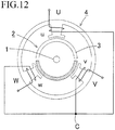
- a three-phase brushless direct current (DC) motor is shown in Fig. 12 as an example of a sensorless motor having no position sensor.
- a rotor 2 is capable of rotating about a rotor shaft 1 and has a permanent magnet 3 having a pair of magnetic poles, i.e., S-pole and N-pole.
- a type of magnetic pole structure e.g., IPM, SPM
- armature coils (coils) U, V and W are formed on pole teeth, which are arranged with a phase difference of 120°, and they are star-connected through a common point C.
- armature coils (coils) U, V and W are formed on pole teeth, which are arranged with a phase difference of 120°, and they are star-connected through a common point C.
- In a three-line type motor only coil lines are extended outward from the motor; in a four-line type motor, a common line too is extended outward.
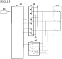
- An example of a block diagram of a conventional three-phase sensorless drive unit is shown in Fig. 13 .
- An MCU (Micro-Control Unit) 51 is a control circuit.
- the MCU 51 stores six energization patterns for the three-phase coils (U, V and W) and magnetic field position information for assigning excitation switching sections (i.e., sections 1-6) of 120°-energization corresponding to each of the energization patterns, and switching-controls a motor driving circuit according to a rotation command sent from a superordinate controller so as to optionally switch an excitation state.
- the unit includes a timer for delaying excitation switching timing for 30°.
- An inverter circuit 52 amplifies control signals sent from the MCU 51, energizes the three-phase coils, and performs a switching action, which is excitation phase switching control or PWM control.
- Half-bridge type switching circuits which can be optionally connected to an electric power line and an earth line, are provided for three phases, and pre-drive circuits for driving output elements (e.g., FET) are also included.
- a comparator circuit (ZERO) 53 is constituted by three comparators, which compare common voltage COM with each of coil voltages U, V and W.
- the common voltage is generated by combining resistances of three phases. It is constituted by many discrete elements, not shown, e.g., hysteresis setting resistance, output level matching resistance, protection element, denoising element.
- Output signals of the comparator circuit 53 are sent to the MCU 51 as position signals.
- the MCU 51 detects a zero-cross point from an edge of output signal of the comparator, delays 30° by the timer, and switches an excitation phase of the inverter circuit 52.
- Fig. 14 Timing of excitation switching which is performed by a conventional position detection manner is shown in Fig. 14 (note that, a waveform of induced voltage will be shown as an approximately straight line in the following explanation). Rotational speed from 0°-phase to 30°-phase is varied with respect to that from -30°-phase to 0°-phase.
- a point A (E1, T1) indicates increasing speed
- a point B (E2, T2) indicate a constant speed
- a point C (E3, T3) indicates reducing speed.
- the timing of excitation switching must be varied in response to change of a rotational speed, but time is constant, i.e., T2, in the conventional delay timer manner, so an error of excitation switching angle, with respect to increasing and reducing speed in the 30°-section, will occur.
- T2 time is constant, i.e., a phase is excessively delayed, and deadlock will occur when accelerating speed, and a phase is excessively advanced, torque will be lowered and step-out will occur.
- position information i.e., rotor angle
- a time axis position information
- correct positions can be estimated only when performing at constant speed, and large errors of angle estimation will occur when increasing and reducing speed.
- estimating the rotor angle according to a time axis causes problems, e.g., lowering motor efficiency, reducing torque, vibration, step-out, increasing current, noise generation.
- step-out is prevented by: for example, stopping output of an energization control circuit when a step-out monitoring circuit detects predictive data of step-out; changing to a free-running state; and then restarting rotation (see Cited Document 1). Further, an electric power supplying to stator coils is restrained from a prescribed time before an energization direction switching point, at which an energization direction is switched, with delaying a prescribed electric angle from an induce voltage zero-cross point where an excitation current of the motor is switched, (see Cited Document 2).
- US2015/188467A1 discloses a motor driving control apparatus that includes: a back-electromotive force detecting unit detecting back-electromotive force generated by a motor apparatus; a zero crossing point estimating unit estimating a zero crossing point by performing at least one of differentiation and integration on a voltage difference between the back-electromotive force and a preset reference voltage; and a controlling unit controlling phase switching of the motor apparatus using the zero crossing point.
- US5023527A discloses control circuit for an electronically commutated motor which has a rotatable assembly and further has a stationary assembly with a plurality of winding stages having terminals for energization, and switches for applying a voltage to one or more of the terminals of the winding stages at a time and commutating the winding stages in a preselected sequence to rotate the rotatable assembly.
- a preselected sequence of winding stages are left correspondingly unpowered so that a plurality of the winding stages are unpowered at some time.
- the winding stages generate back emf signals and also couple electrical signals from each energized winding stage to the unpowered winding stages which signals can interfere with detection of back emf for position sensing purposes.
- the control circuit includes a first circuit for selecting at least two of the unpowered winding stages which have electrical signals coupled to them that have a predetermined relationship in polarity and magnitude.
- a second circuit produces an electrical output from the voltages on the winding stage terminals of the winding stages selected, so that the electrical signals coupled from each energized winding stage are substantially canceled when they have the predetermined relationship while the back emf is preserved for position sensing substantially free from interference from the electrical signals that are coupled from each energized winding stage to the unpowered winding stages.
- US4162435A discloses a method and apparatus for electronically commutating a direct current motor not requiring position sensors but rather sampling induced voltage across an unenergized motor winding to derive control signals therefrom.
- One motor winding is energized while the voltage across another winding is sampled and integrated to provide a flux indication.
- the integrated voltage sample is compared to a reference and when that integrated value exceeds the reference, the next winding of the motor is enabled and the voltage integral returned to an initial value.
- a ring counter maintains an indication of the currently energized winding and may also be employed to cause the sampling circuit to sample the induced voltage on the winding next in the motor sequence to be energized.
- the zero-cross point is selected, and excitation is switched by using timer, etc., so an excitation switching phase is advanced when a motor load is applied and the motor speed is reduced, so torque is reduced; and then if the load is released, the motor speed is increased and the excitation switching phase is delayed, so the torque is reduced.
- an excitation switching phase is advanced when a motor load is applied and the motor speed is reduced, so torque is reduced; and then if the load is released, the motor speed is increased and the excitation switching phase is delayed, so the torque is reduced.
- sensorless motors are not employed in some uses in each of which viscous load is extremely varied due to occurring of step-out, so they are mainly used in, for example, a spindle motor for a hard disk drive unit in which load variation is small.
- the present invention has been invented to solve the above described problems, and an object of the present is to provide a method for driving a three-phase permanent magnetic field-type DC brushless motor having no position sensor, wherein the method is different from a conventional rotor position estimation method according to a time axis and performs rotor position estimation according to an angle axis, thus making it possible for excitation switching to always be achieved at an optimal angle in response to a change in speed.
- the problems can be solved by detecting a rotor angle without using a time axis.
- the rotor angle is obtained by time-integrating angular speeds, i.e., induced voltage because the rotor position can be obtained by time-integrating rotor speeds.
- This position detecting manner is defined as an induced voltage time-integration manner. It will be explained later.
- the method performs rotor position estimation according to an angle axis, without performing estimation according to a time axis, thus making it possible for excitation switching to always be achieved at an optimal angle in response to a change in speed, so that a motor efficiency can be highly improved. Further, output voltage can be increased by reducing torque ripples, a consumption current can be simultaneously reduced, and heat generation of the motor can be reduced. Especially, in a small-sized brushless DC motor having a hall sensor, influences of sensor errors and magnetization errors are large, but the sensorless driving method is not influenced by the errors, so an operation efficiency thereof is higher than that of the motor having a hall sensor.
- the correction according to phase errors of lead angles and delay angles is repeated, so that excitation switching can be always performed at a desired position which is near a cross-point of induced voltage and at which a minute lead angle is set.
- torque ripples can be reduced, and torque can be increased, so that an effect like performing speed control can be obtained.
- the control circuit obtains neutral point potential offset voltage by "(Vb-Vc)/(a measured frequency of the resetting period)" and adds it to neutral point potential when ending the resetting period.
- control circuits stores an integration peak value of induced voltage component of the previous excitation section, calculates an average of the previous integration peak value and a present integration peak value so as to obtain a section angular moving average when detecting the integration peak value of induced voltage component of the present excitation section, sets the obtained integral value as a threshold value for determining an end of excitation section, switches an excitation section on the basis of the threshold value, and repeats to obtain a section angular moving average of two sections and corrects the threshold value with advancing excitation sections.
- a phase angle of the excitation section end-side is corrected to obtain an average angle of the present and previous excitation sections, so that vibration and occurring a long period excitation section can be prevented.
- control circuit may perform lead angle control by delaying an integration starting position for a prescribed time or shifting an integration threshold value, which is a standard value for determining an end of an excitation section, by a prescribed value so as to forwardly shift a phase angle for switching excitation.
- control circuit may start the motor by direct current energization, with performing PWM control with duty ratio of 100 % or linear drive in at least a first excitation section, when the rotor is started and positioned near a starting angle of an excitation section, then may measure induced voltage and may perform the integration
- the position detection of the rotor does not depend on a rotational speed, so the method can be useful even if induced voltage is gradually or intermittently induced; further, the detected minute induced voltages are integrated and made a large integral value, so that the rotor position can be stably detected.
- control circuit may measure non-energization phase voltage for each measuring period and make a present measured value zero or not perform the integration of induced voltage component when a present measured value is equal to a previous measurement value.
- the control circuit previously sets a prescribed prohibition period for an optional excitation section, during which determination of an end of the section is prohibited or during which determination of a section end is prohibited in case that the section end is detected in an abnormally short time when switching an excitation section after starting the rotation of the rotor, sets a measurement prohibition period, which is about an electric time constant ⁇ ⁇ , immediately after energization of an excitation section, then measures non-energization phase voltage for each measuring period and integrates them, and performs the integration only, without determining an end of excitation section, until elapsing the prohibition period during which determination of a section end is prohibited.
- the integral value never exceeds a threshold value, so that erroneous determination caused by a large signal or noise can be prevented.
- the suitable prohibition period may be previously set on the basis of starting conditions, etc. and may be changed according to the rotation speed.
- control circuit may detect an initial position in case that an end of excitation section is not detected until elapsing a stop determination period, which has been previously set, after beginning energization of the excitation section, may excite a relevant excitation section in case that the rotor exists in any of the present excitation section, the previous excitation section and a next excitation section, and may perform a first manner for restarting the motor or a second manner, in which self-excitation positioning is performed in a present excitation pattern, without detecting the initial position, so as to restart the motor, in case that the rotor exists in other excitation sections.
- the motor can be returned to a normal rotation state; and, by the second manner, probability of reverse rotation can be restrained, the rotor can be compulsorily stopped at a prescribed position, and the motor can be started by excitation corresponding to said position.
- the excitation switching can be always performed, at an optimum angle in response to a change in speed, by detecting the rotor angle without depending on a time axis, so that a motor efficiency can be highly improved.
- the output voltage can be increased by reducing torque ripples, a consumption current can be simultaneously reduced, and heat generation of the motor can be reduced.
- influences of sensor errors and magnetization errors are large, but the sensorless driving method is not influenced, so an operation efficiency is higher than that of the motor having a hall sensor.
- precise lead angle control can be performed when increasing and reducing speed, spike pulses occurring when the excitation switching is performed are reduced and high frequency waves are restrained, so that rotation noise, which is generated especially in a load operation, can be highly reduced.
- the lead angle control is capable of effectively generating reluctance torque and is capable of not only improving the motor efficiency but also increasing torque and reducing a consumption current.
- a field- oriented control in which the position can be detected while increasing and reducing speed without depending on the speed, is performed, a time of increasing speed can be shortened, the motor can be started in a short time, and deadlock and step-out can be prevented.
- a calculation time for position detection can be short, and a measuring period of induced voltage can be shortened, so a high-speed rotation, whose rotational speed is several times as fast as that of PWM-driven rotation, can be realized in case of performing linear drive.
- the method does not depend on motor properties and a load current and is capable of operating without selecting a type of motor and operation conditions, so it can be applied to wide uses. Further, the method can be easily used because setting parameters and adjustment are not required.
- a zero-cross comparator, a hysteresis setting circuit, a common generating circuit, etc. are not required, the circuits can be simpler, an interface part can be constituted by only six dividing resistances, no active parts are required, so that the method can easily applied to a high voltage system, and troubles can be reduced.
- Control programs can be simpler, a developing time of software can be shortened, a high-performance CPU is not required due to small calculation load, and cost for both of hardware and software relating to the driving circuit can be reduced.
- a high-performance system which basically has high noise resistance, can be constituted, and a starting performance can be improved so that the motor can be securely started. Therefore, secure operation under noise environment, stall operation, a reciprocating motion including butting and stopping actions, all of which cannot be performed by the conventional sensorless driving manner, can be performed.
- Embodiments of the method of the present invention for detecting a rotor position of a sensorless motor will now be described with reference to the attached drawings.
- the present invention can be widely applied to a sensorless driving method for sensorless-driving a sensorless motor comprising: a rotor 2 having a permanent magnetic field 3; and a stator 4 having star-connected coils, which are arranged with a phase difference of 120° and in which phase ends are connected to a motor driving circuit (see Fig. 12 ).
- a method for sensorless-driving a three-phase DC brushless motor will be explained, as an example, with reference to the structure thereof.
- the three-phase brushless DC motor has a two-pole permanent magnet rotor and a stator 4 having three slots.
- the motor may be an inner rotor type or an outer rotor type.
- the rotor 2 is integrated with a rotor shaft 1, and a two-pole permanent magnet 3 is provided as a magnetic field.
- the stator 4 facing the permanent magnet 3 has pole teeth U, V and W, which are arranged with a phase difference of 120°.
- Coils u, v and w are respectively formed on the pole teeth U, V and W, the phases are connected at common C, and they are connected to the motor driving system, which will be described later, as the three-phase brushless DC motor. Note that, a common line is not required, so it is omitted in the drawing.
- An excitation manner is "one-phase 120°-bipolar rectangular wave energization manner" or the like.
- An MCU 5 Micro-Control Unit: control circuit
- the MCU 5 controls output signals, which are outputted from output terminals OUT 1-OUT 6 and sent to an inverter circuit 7 (INV: a motor driving circuit), according to rotation commands (RUN) sent from a superordinate controller 6. Further, the MCU 5 sends rotor position information and rotational direction information to the superordinate controller 6.
- the inverter circuit 7 usually switches an excitation phase or performs switching actions, e.g., PWM control.
- the inverter circuit 7 includes diodes, which are respectively connected in reversely parallel to switching elements, and half-bridge type switching circuits for each phase, which are capable of being optionally connected to a positive pole power source line and an earth power source line (a three-phase bridge circuit).
- the MCU 5 controls the inverter circuit 7 so as to energize any two of the three phase coils according to the rotation commands sent from the superordinate controller 6.
- a voltage measuring circuit 8 measures voltages of the coils energized by the inverter circuit 7.
- the voltage measuring circuit 8 is connected to the MCU 5 through a voltage divider circuit 9 (RA), which matches voltage of each phase coil energized by the inverter circuit 7 within a measurable input range if necessary.
- the MCU 5 further includes: an A/D converter 10 (ADC) for measuring voltage of each phase coil inputted through the voltage divider circuit 9; and an integration counter 11 (CT) for integrating an induced voltage component included in the voltage of each phase coil.
- ADC A/D converter 10
- CT integration counter 11
- the zero-cross comparator (ZERO) is omitted, but the coil voltages are adjusted (conditioning) within the input range by the divider circuit 9 and inputted them to the A/C converter 10 in the MCU 5 instead of the zero-cross comparator. Note that, no common voltage is used, so the motor may be a three-line type motor.
- the divider circuit 9 is constituted by three sets of dividing resistances (r1, r2), (r3, r4) and (r5, r6), each of which is constituted by two resistances (e.g., r1 and r2) serially connected. One end of each dividing resistance is connected to the coil, and the other end thereof is connected to the earth. Output voltages are made small according to division rata (i.e., r2/(r1+r2), r4/(r3+r4), r6/(r5+r6)) and matched within the input range of the A/D converter 10. It can be applied to a high voltage driver circuit by increasing the partial voltage ratio. For example, in case that the partial voltage ratio is 1:99, a coil voltage becomes 1/100, so a voltage of 330V can be measured by a 3.3V-full range A/D converter.
- the MCU 5 includes the three-channel A/D converter 10 so as to measure coil voltages.
- the integration counter 11 (CT) for integrating the coil voltages is also included.
- the A/D converter 10 measures voltage of each phase at a certain period, a standard sample holding circuit having one channel may be used, but a three-channel sample holding circuit capable of performing simultaneous sampling is preferable so as to eliminate measurement timing errors.
- the sensorless driving controlled by the MCU 5 will be explained.
- the MCU 5 detects that the rotor 2 reaches an excitation section starting point while rotating at a rotation number enabling detecting induced voltage, and starts to energize the phase, which is energized by the inverter circuit 7, with switching a energization pattern of the energized phase to that corresponding to a present excitation section.
- a count value of the integration counter 11 is reset immediately after the inverter circuit 7 starts energization.
- the A/D converter 10 measures coil voltages at a certain measuring period. Induced voltage components are extracted from the coil voltages measured by the A/D converter 10 and integrated by the integration counter 11. If the integral value reaches or exceeds zero immediately after the integration counter 11 starts the integration, the excitation in the present excitation section is terminated. By repeating the above described steps, the motor can be continuously rotated.
- the above described manner for driving the sensorless motor is defines as an induced voltage time-integration manner, and this manner will be explained.
- an induced voltage E By integrating an induced voltage E with a time T from a starting position of an excitation section, an induced voltage is changed at a center position, so the integral value reaches zero at an excitation section ending position. Therefore, an excitation section switching position can be known (hereinafter merely referred to as "60°-excitation section").
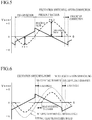
- Fig. 1 shows waveforms of induced voltage (solid lines) and a waveform of an integral value thereof (dotted line), with respect to an angle axis, while performing 120°-energization.
- a horizontal axis is an angle axis indicating a rotor angle ⁇
- a vertical axis an indicates induced voltage and an integral value (i.e., ET integration)
- the point 0 is neutral point potential.
- the waveforms indicate that the rotor 2 rotates at a constant speed
- shown waveforms relating to the following explanation are those at a constant rotational speed except some cases.
- An object non-energization phase is switched for each section, the U-phase is firstly selected as the non-energization phase in Fig. 1 , and induced voltage (high speed Eu; thick solid line) with respect to the 0 point is measured, then the phase is switched to the W-phase in the next section, and induced voltage (high speed Ew; thick solid line) is measured. For reference, induce voltage at low speeds (low speeds Eu and Ew; thin solid lines) are also shown.
- the integral value is an integral value of induced voltages measured at a minute measuring period. According to the waveform of the integral value of Eu, the integral value starts from zero and takes a negative value and returns to zero at the excitation switching point. Similarly, the integral value of Ew starts from zero and takes a positive value and returns to zero at the excitation switching point. Namely, the integral value becomes zero at two points whose angles centered at a zero-cross point are equal, so the excitation switching point, i.e., section ending point, is the position at which the integral value integrated from the section starting point becomes zero again. This is a principle of the induced voltage time-integration manner for detecting the position of the rotor.
- Fig. 2 is an explanation view of the integration, and integral values of the measured values Eu and Ew at constant speed are shown with respect to a time axis.
- a vertical axis indicates an induced voltage and an integral value
- a horizontal axis indicates time
- a measuring period t is, for example, a PWM carrier period.
- Waveforms of integral values show integral values which are obtained by integrating induced voltages e1-en at the measuring period t and which form Riemann integration waveforms. Note that, the integral value will exceed zero due to quantization errors, so resetting the integral value is performed when switching the excitation section.
- the excitation is started at the section starting point, induced voltages are measured and integrated at the certain period, and the section ending point is detected when the integral value becomes zero. Then, an energization pattern is changed to that for the next section, and the above described integration is repeated, so that the motor can be continuously rotated.
- the induced voltage time-integration manner is applied with being synchronized with the section starting point while rotating the motor at a rotation number enabling detecting the induced voltages. By treating only zero point of the integral value, the manner does not depend on the rotational speed, and adjusting time constant is not required.
- an induced voltage can be extract from a difference between "non-energization phase voltage or common voltage and neutral point potential (1/2 of energization inter-phase voltage)", or a difference between "common voltage and non-energization phase voltage”.
- An object is to perform the excitation switching at a cross-point of induce voltages of the adjacent sections, a state where the excitation switching is performed in an induce voltage cross-point phase is defined as a no error state, and a phase difference of the induced voltage occurring in a state where the excitation switching is performed at a position deviated from the induce voltage cross-point is defined as a phase error.
- the phase difference occurring in a state where the excitation switching is performed before reaching the induce voltage cross-point is defined as a lead angle error; the phase difference occurring in a state where the excitation switching is performed after reaching the induce voltage cross-point is defined as a delay angle error, and the both errors are respectively corrected by different correction manners in the present embodiment.
- Fig. 3 explains the lead angle error.
- the drawing shows a waveform of induced voltage (solid line), a waveform of the integral value thereof (thin dotted line) and a waveform of a corrected integral value (thin dotted line).
- the sections, each of which is sectioned at the induced voltage cross-points in the no error state, are indicated as desired section angles.
- a symbol ⁇ a stands for a phase error (lead angle)
- a symbol Va stands for a final measured value of induced voltage in the section 1
- a symbol Vb stands for a first measured value of induced voltage in the section 2
- a symbol Vc stands for voltage of theoretical induced voltage cross-point and is obtained by "Va+(Vb-Va)/2”.
- a symbol Voff stands for offset of neutral point potential 0 (described later).
- the value Va sharply increases to Vb.
- the lead angle occurs, and a period occurring the phase error ⁇ a, from Vb to the voltage Vc of the induced voltage cross-point, is a phase error period when occurring the lead angle, so the integration is prohibited.
- a resetting period during which the integral value is fixed to zero in the period occurring the phase error ⁇ a or until the measured value of induced voltage exceeds the voltage Vc of the induced voltage cross-point and during which the integration is not performed, is set.
- Fig. 4 explains the delay angle error.
- a symbol Vc' stands for voltage of a previous induced voltage cross-point
- a symbol Vd stands for an induced voltage threshold value for determining an end of a section.
- the cross-point (Voltage Vc') of induced voltage cannot be detected because the position of the rotor has already passed through the induced voltage cross-point, so correcting phase error cannot be performed.
- the integration is started immediately after an excitation section is changed and the first Vb is measured. In this case, a section angle after the correction is small, so a lead angle occurs in the next section.
- an excitation switching phase is determined under the following hypothetical conditions: the rotational speed is constant during the delay angle section; and the voltage Vc' of the previous induced voltage cross-point and the voltage Vd of the next cross-point are equal. Namely, the integration is not performed when the delay angle occurs, and the excitation switching is performed on the basis of the voltage Vd, which is a threshold value and at which an induced voltage exceeds a standard voltage Vref by a value equal to the previous cross-point voltage Vc'.
- a waveform of the induced voltage on the end-side of the section 2 and the excitation switching point are corrected by the second manner, and an excitation switching angle is shown.
- the delay angle can be rapidly corrected and advanced.
- the excitation switching can be always performed at a desired position which is near the cross-point of induced voltage and at which a minute lead angle is set.
- the MCU 5 obtains neutral point potential offset voltage by "(Vb-Vc)/(a measured frequency of the resetting period)" and adds it to neutral point potential when ending the resetting period.
- the neutral point potential is a standard voltage for measuring induced voltage, and high accuracy value is required.
- coil voltage of two energization phases, and "(energization inter-phase voltage)/2" must be set as the neutral point potential.
- the neutral point potential is varied by resistance deviation or variation of source voltage; if the neutral point potential is set as a constant value, offset errors will occur and will cause vibration.
- Voff ((Vb-Va)/2)/(measured frequency of the resetting period)”.
- the control circuits stores an integration peak value of the previous excitation section, calculates an average of the previous integration peak value and a present integration peak value so as to obtain a section angular moving average when detecting the present integration peak value, sets the obtained value as a threshold value for determining an end of integration section, switches an excitation section on the basis of the threshold value so as to correct an end phase of integration section, and repeats to obtain the section angular moving average of two sections and corrects an end phase of integration section with advancing excitation sections.
- the MCU 5 stores an integration peak value as an integration peak value of the previous section at the ending position of the section.
- an integration peak value is detected by comparing integral values, for each measuring period, in the present excitation section after switching the excitation section.
- the integration peak value it is set as the integration peak value of the present section, an average of the stored integration peak value of the previous section and the integration peak value of the present section is obtained, then the obtained value is set as the integration threshold value for determining the end of the section.
- the section ending position is determined when the measured value exceeds the threshold value, and the excitation is switched.
- the section angles are corrected as well.
- Fig. 5 is an explanation view of the section angular moving average.
- a symbol PK1 stands for the integration peak value of the previous section
- a symbol PK2 stands for the integration peak value of the present section
- the threshold value is "(PK1 + PK2)/2".
- the section ending point is forwardly moved by an amount of the correction.
- an average angle between the previous and the present sections is set by correcting a phase angle of the section end position, so that occurring vibration and a long period section can be prevented.
- the control circuit performs lead angle control by delaying the integration starting position for a prescribed time or shifting the integration threshold value, which is the standard value for determining the end of the excitation section, by a prescribed value so as to forwardly shift the phase angle for switching excitation.
- the lead angle control means that the section starting position and the section ending position are forwardly phase-shifted, with respect to the normal positions, without changing a width of the section.
- a phase of a coil current is delayed with respect to that of a coil voltage, so the lead angle control, in which the excitation switching is performed at a phase angle earlier than that of the induced voltage cross-point, has been widely performed. Further, it is used to increase torque by taking advantage of reluctance torque. Generating spike current and noise can be reduced by the lead angle control.
- a first manner of the lead angle control is delaying the integration starting position for an optional time (corresponding to the measured frequency). By this manner, a position exceeding zero on the section end-side is forwardly shifted for the optional time so as to delay the start of integration, and the excitation switching phase is advanced, so that the lead angle control is performed.
- An amount of leading angle may be set from 0° to about 30°, and the amount of leading angle may be changed for each section.
- Fig. 6 is an explanation view of the leading angle caused by delaying the start of integration.
- a waveform of induced voltage (solid line), a waveform of integral value under no lead angle control (thin dotted line) and a waveform of integral value under the lead angle control (dotted line) are shown in the drawing.
- the excitation switching is performed at a phase angle which is forwardly advanced, with respect to an induced voltage cross-point phase, by the angle of delaying the start of integration.
- a second manner of the lead angle control in which the threshold value for detecting the next excitation switching point from the integral value, will be explained.
- the threshold value is zero.
- desired offset is set on the positive side when the integral value is a positive value; and desired offset is set on the negative side when the integral value is a negative value.
- Fig. 7 is an explanation view of setting the lead angle on the basis of the threshold value.
- a waveform of induced voltage (solid line) and a waveform of integral value under the lead angle control (dotted line) are shown in the drawing.
- the excitation switching is performed before reaching zero on the basis of the integral value for determining the section end, so the difference makes the lead angles.
- the MCU 5 starts the motor by direct current energization, with performing PWM control with duty ratio of 100% or linear drive in at least a first excitation section, when the rotor is started and positioned near a starting angle of an excitation section, then measures induced voltages and performs the integration.
- the section starting position is the integration starting position, so it is necessary, in a case that the method is applied from starting the motor, to detect the initial position of the rotor in a stationary state and apply the method after rotating the rotor 60° or less until reaching the section starting position of the next section.
- Various manners for detecting a rotor position in a stationary state and a state of extremely low speed have been proposed, so any of the manners is not assigned in the present embodiment.
- the initial position (the section 1) is detected, and the excitation is performed on the basis of the initial position so as to start the rotation. Then, the position detection is periodically performed to check if the position reaches near the starting position of the next section 2 or not.
- the control method is switched to the method of the present invention.
- positioning at the section starting position can be performed by a manner of self-excitation positioning.
- the starting can be performed by a simple process, in which detecting the initial position can be omitted.
- an optional phase is energized by phase-locked energization so as to position the rotor 2 at a specific position.
- the rotor when energization is performed from the U-phase to the common, the rotor is rotated until a phase of 180°, and then torque becomes zero and the rotor stops there.
- the rotor 2 is stopped by a resultant force of the U- and V-phases and remains stationary at a position of 150° with a holding power which is a half of peak torque.
- This phase angle is the starting position of the section 3.
- the rotor 2 can be positioned at an optional section starting position, which starts from 30° and advances at 60°-step. This manner is the self-excitation positioning manner. In case that the initial position is unknown, the rotor is positioned at an optional section starting point, so, in some cases, the rotational angle for positioning becomes unstable, and reverse rotation occurs.
- the method of the present embodiment is applied to start the excitation, but the speed in the first excitation section is nearly zero and an induced voltage is scarcely generated.
- the ⁇ V is greater than an induced voltage
- voltage relating to inductance variation is overlapped with the non-energization phase voltage during the pulse drive, so it is impossible to detect correct induced voltages.
- the motor is started by direct current energization, with performing the PWM control with duty ratio of 100%, or linear drive in at least the first excitation section.
- the inductance variation is not reflected to the non-energization phase voltage, so that minute induced voltage can be detected.
- adjustment of a starting current or starting torque is performed by changing the source voltage V applied to the inverter circuit 7 without reference to the PWM drive and the linear drive (see Fig. 10 ).
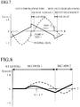
- Fig. 8 is a waveform chart showing a waveform (solid line) of induced voltages and a waveform (dotted line) of the integral values, with respect to a time axis, when starting.
- Vref stands for neutral point potential.
- the induced voltage is zero when starting, and then the induced voltage is gradually generated.
- the method does not depend on speed, so that the induced voltage which is gradually increased or intermittently generated can be used.
- the detected minute induced voltages are integrated to make a large integral value, so that the rotor position can be stably detected.
- the MCU 5 measures non-energization phase voltages at the measuring period, and it makes the present measured value zero or does not perform the integration when the present measured value and the previous measured value are equal, or an electric potential difference between the two is equal to a quantization error or less.
- the present measured value may be considered as "(previous measured value + present measured value)/2".
- the control circuit makes the present measured value zero or does not perform the integration when the present measured value and the previous measured value are equal or when an error is equal to a quantization error or less.
- the above described state in which the present measured value is equal to the previous measured value, indicates that the rotor is stopped and in the stationary state.
- the starting action is performed in several milliseconds, but if the rotor is held by an external force, it sometimes takes several seconds to start the motor.
- restriction of a stationary time is released, so that stall operation, etc. can be performed.
- the MCU 5 previously sets a prescribed prohibition period for an optional excitation section, during which determination of an end of the section is prohibited or during which determination of a section end is prohibited in case that the section end is detected in an abnormally short time when switching an excitation section after starting the rotation of the rotor, sets a measurement prohibition period, which is about an electric time constant ⁇ ⁇ , immediately after energization of an excitation section, then measures non-energization phase voltage for each measuring period and integrates them, and performs the integration only, without determining an end of excitation section, until elapsing the prohibition period during which determination of a section end is prohibited.
- a low speed rotation range can be advantageously extended and a starting performance can be improved by detecting minute induced voltage signals as much as possible, but it is improper to employ a lowpass filter so as to remove noise because the signals too will be removed by the filter.
- the induced voltage is not measured within an unstable period, which is immediately after the energization and in which spike pulses of about the electric time constant ⁇ ⁇ are generated.
- the non-energization phase voltages are directly integrated without passing through the lowpass filter.
- Noise components are usually positive and negative symmetrically appeared, so the noises cancel each other by performing the integration without processing the noises; on the other hand, the induced voltage is unevenly generated and shifted to the positive-side or the negative-side, so it can be effectively integrated without being cancelled. Therefore, noise cancellation with large S/N ratio can be performed without phase delay.
- the beginning period is a period sensitive to noise.
- the prohibition period during which the integration is performed until the integral value becomes sufficiently large and the determination of the section end is prohibited, is set.
- the period of the section 1 is a fixed value (e.g., 1 millisecond), that of the section 2 is 25% of the previous section, and no period is set for the section 3 and further sections.
- a fixed value e.g. 1 millisecond
- the period of the section 1 is a fixed value (e.g., 1 millisecond)
- that of the section 2 is 25% of the previous section
- no period is set for the section 3 and further sections.
- a certain determination prohibition period may be set so as to secure the minimum section time width. For example, 50% of the section time of the previous section is set as the determination prohibition period.
- noise can be strongly removed with detecting the minute induced voltages, so that the excitation switching can be performed at the correct positions.
- the MCU 5 detects the initial position again, performs the excitation in the present section when the rotor exists in the present section, the previous section or the next section, and performs a first manner, in which the motor is restarted, or a second manner, in which the self-excitation positioning is performed, by the present excitation pattern, to restart without detecting the initial position when the rotor exists in other sections.
- the rotation cannot be detected. If rotation at the extremely low speed, which is caused by an external force, etc., is continued, the section is advanced to the next one, but the circuit cannot be detected the advancement, then the rotation is stopped by holding torque, which is a half of the maximum torque, when reaching a self-excitation stopping position and becomes the deadlock state. If the rotor is compulsorily rotated by an external force, reverse rotation torque is generated and makes the rotor return to the deadlock position. These actions are unfavorable for the motor control, so constant torque should be generated in a constant direction.
- the first manner is performed by detecting the initial position as well as starting the motor so as to confirm the rotor position. The measurement of induced voltages and the integration are not performed.
- the present excitation As a result, if the rotor exists in the present section, the present excitation, the measurement of induced voltages and the integration are continued as they are. If the rotor forwardly advances to the next excitation section, the excitation pattern is switched to that for the next excitation section. If the rotor backwardly advances to the previous excitation section, the excitation pattern is switched to that for the previous excitation section.
- a position estimation error is determined, then the self-excitation positioning corresponding to the section is performed, on the basis of the redetected initial position, so as to restart, and the present manner is applied when detecting the section starting point of the next section.
- a time for detecting the section starting point of the next section is monitored using the stop determination period, and the step may be returned to the initial position detection when elapsing the detection time.
- the rotor can escape from the deadlock state and the reverse rotation state, which are caused by noise, unexpected external forces or position estimation errors, and can return to the normal rotation state.
- the stop determination period may be optionally set on the basis of use conditions; in case that, for example, the initial position detection time is about 1 millisecond and the stop determination period is set about 100 milliseconds, the initial position detection is repeated at about 100 milliseconds. In this case, energization efficiency is about 99%, sufficient torque can be secured, and sensing sound caused by the position detection action is 10 Hz which is lower than an audible range.
- the state is considered as the deadlock state when elapsing the stop determination period. It is thought that the deadlock state is occurred by the self-excitation positioning with the present excitation pattern. Therefore, the rotor may be restarted by performing the self-excitation positioning with the present excitation pattern. By this manner, a probability of reverse rotation is reduced, the rotor 2 is compulsorily stopped at a prescribed position, and it can be restarted by the excitation corresponding to that position.
- any one of the manners may be performed.
- the superordinate controller 6 sends the rotation command RUN to the MCU 5 to start the motor, and the method relating to the present invention is applied when the rotation number of the rotor 2 reaches the rotation number enabling detecting induced voltages, thus basic actions will be explained.
- the motor is started, and the excitation is started with the energization pattern corresponding to number of the present excitation section when the MCU 5 detects the excitation section starting position after the rotation number reaches the rotation number enabling detecting induced voltages (STEP 1).
- the integral value (CNT) is reset to zero (STEP 2).
- the MCU 5 measures the coil voltages of the energization phases, by A/D-converting the coil voltages of the energization phases with the A/D converter 10, at a certain period T (STEP 3).
- the induced voltage value E is calculated by obtaining a difference between non-energization phase voltage Vz and 1/2 of energization inter-phase voltage V (i.e., "V/2" is neutral point potential) (STEP 4).
- the integration counter 11 adds the induced voltage value E to the integral value (CNT) (the integration: STEP 5).
- a step of extracting the induced voltage components from the coil voltages and integrating them is performed, by PWM interrupt control, at the certain period T (STEP 6).
- the MCU 5 stops the energization and terminates the routine (STEP 7).
- determining if the integral value (CNT) of the integration counter 11 reaches zero or not is performed (STEP 8: waiting for ending of the excitation section). If the integral value (CNT) of the integration counter 11 does not exceed zero, the action is returned to STEP 3 so as to continue the integration. On the other hand, if the integral value (CNT) of the integration counter 11 exceeds zero, the excitation section is ended, and the excitation is advanced to the excitation section of the next number (STATE+1), and the action is returned to STEP 1 so as to start the excitation for the next excitation section (STEP 9).
- the above described basic position detection and energization routine are simply performed by: measuring the induced voltages, by, for example, PWM interrupt control, at the certain period; integrating the measured voltages; and switching the excitation section to the next excitation section when the integral value exceeds zero. Therefore, calculation time can be shortened, and a speed control process of a main routine, etc. can be performed in good time.
- a practical program can be produced by adding the functions of the phase compensation for the excitation switching and the lead angle control. In the present embodiment, calculation loads relating to these additional functions are reduced. Further, by adding the functions of the initial position detection and the self-excitation positioning, the method of the present embodiment can be applied from starting the motor.
- the structure of the motor circuits and the structure of the control programs may be variously varied, and they are not limited to the above described embodiment.
- the present invention is capable of making a contribution to widely extend use of the sensorless motors having superior properties, e.g., low cost, high environment resistance, high reliability, high resource saving, high energy saving, and its social significance is great.
Claims (8)
- Verfahren zum Ansteuern eines sensorlosen Motors, der einen bürstenlosen Dreiphasen-Gleichstrommotor ohne Positionssensor ausbildet, wobei der sensorlose Motor Folgendes umfasst:eine Motoransteuerschaltung (7), die eine Dreiphasen-Brückenschaltung umfasst, um beliebige zwei der Dreiphasen-Spulen zu bestromen, die durch einen gemeinsamen neutralen Punkt (C) sterngeschaltet sind;eine Steuerschaltung (5) zum Steuern der Motoransteuerschaltung (7) gemäß einem Drehbefehl, der von einer übergeordneten Steuerung (6) gesendet wird; undeine Spannungsmessschaltung (8) zum Messen einer Spannung der Spulen, die von der Motoransteuerschaltung (7) bestromt werden,wobei die Spannungsmessschaltung (8) Folgendes umfasst: eine Spannungsteilerschaltung (9) zum Abgleich einer Spulenspannung jeder der Phasen-Spulen, die von der Motoransteuerschaltung (7) bestromt werden, innerhalb eines messbaren Eingangssignalbereichs, falls erforderlich; einen Analog-Digital-Wandler (10) zum Messen der Spulenspannung jeder der Phasen-Spulen, die durch die Spannungsteilerschaltung (9) eingespeist wird; und einen Integrationszähler (11) zum Integrieren einer induzierten Spannungskomponente, die in der gemessenen Spulenspannung jeder der Phasen-Spulen enthalten ist,wobei das Verfahren zum Ansteuern des sensorlosen Motors das kontinuierliche Drehen des Motors durch das Wiederholen der folgenden Schritte durch die Steuerschaltung (5) umfasst: das Detektieren einer Erregungsabschnitt-Startposition durch den Integrationszähler (11), während ein Rotor (2) mit einer Drehzahl, die das Detektieren einer induzierten Spannung ermöglicht, oder höher gedreht wird; das Beginnen, die Phase zu bestromen, die von der Motoransteuerschaltung (7) bestromt wird, wobei von einem Bestromungsmuster der bestromten Phase auf jene, die einem gegenwärtigen Erregungsabschnitt entspricht, umgeschaltet wird, wenn der Integrationszähler (11) die Erregungsabschnitt-Startposition detektiert; das Zurücksetzen des Integrationszählers (11) unmittelbar nachdem die Motoransteuerschaltung (7) mit der Bestromung beginnt; das Messen einer Spulenspannung zu einer bestimmten Zeitspanne durch den Analog-Digital-Wandler (10), das Extrahieren einer induzierten Spannungskomponente aus der Spulenspannung, die von dem Analog-Digital-Wandler (10) gemessen wird, und das Integrieren der induzierten Spannungskomponente durch den Integrationszähler (11); und das Beenden des Erregungsabschnitts, wenn der Integralwert null erreicht oder übersteigt, nachdem der Integrationszähler (11) mit dem Integrieren begonnen hat,wobei die induzierte Spannungskomponente aus einer Differenz zwischen einer Nichtbestromung-Phasenspannung oder einer gemeinsamen Spannung und einem Potenzial des neutralen Punkts oder aus einer Differenz zwischen der Nichtbestromung-Phasenspannung und der gemeinsamen Spannung extrahiert wird, undwobei das Verfahren außerdem das Durchführen eines Schritts einer Kompensation eines Phasenfehlers, der durch einen Vorauseilungswinkel und einen Verzögerungswinkel hervorgerufen wird, durch die Steuerschaltung (5) umfasst, wobei im Falle einer vorauseilenden Phase, in der "eine induzierte End-Spannung Va eines vorangegangenen Erregungsabschnitts < eine erste induzierte Spannung Vb des gegenwärtigen Erregungsabschnitts", wenn ein Erregungsabschnitt geschaltet wird, eine theoretische Durchgangspunktspannung Vc einer induzierten Spannung durch "Va+(Vb-Va)/2" erhalten wird, und eine Zurücksetzungszeitspanne, während der ein Integralwert zurückgesetzt wird, bis ein gemessener Wert einer induzierten Spannung Vc oder weniger erreicht, eingestellt wird; im Falle einer Verzögerungsphase, in der "Va > Vb" beim Schalten eines Errregungsabschnitts ist, eine beliebige Art einer ersten Art, wobei das Integrieren ab der ersten Messung von Vb beginnt, einer zweiten Art, wobei ein Schwellwert Vd durch "-(Va+Vb)/2" ohne Durchführen einer Integration erhalten wird und ein Erregungsabschnitt geschaltet wird, wenn ein gemessener Wert einer induzierten Spannung Vd erreicht oder übersteigt, und einer dritten Art, wobei der Schwellwert als "Vd=-Vb" ohne Durchführen einer Integration eingestellt wird, und ein Erregungsabschnitt geschaltet wird, wenn ein gemessener Wert von induzierter Spannung Vd erreicht oder übersteigt, ausgewählt und durchgeführt wird und wobei die Phasenkompensation jedes Mal beim Schalten eines Erregungsabschnitts wiederholt wird.
- Verfahren zum Ansteuern eines sensorlosen Motors nach Anspruch 1, wobei im Falle einer vorauseilenden Phase beim Schalten eines Erregungsabschnitts das Verfahren außerdem das Erhalten einer Offsetspannung des Potenzials des neutralen Punkts durch "(Vb-Vc)/(eine gemessene Häufigkeit der Zurücksetzungszeitspanne)" durch die Steuerschaltung (5) und deren Addieren zu dem Potenzial des neutralen Punkts bei Beendigung der Zurücksetzungszeitspanne umfasst.
- Verfahren zum Ansteuern eines sensorlosen Motors nach Anspruch 1, wobei das Verfahren außerdem das Speichern eines Integrationsspitzenwerts einer induzierten Spannungskomponente des vorangegangenen Erregungsabschnitts durch die Steuerschaltung (5), das Berechnen eines Mittelwerts des vorangegangenen Integrationsspitzenwerts und eines gegenwärtigen Integrationsspitzenwerts, um einen Abschnittswinkelbewegungsmittelwert beim Detektieren des Integrationsspitzenwerts der induzierten Spannungskomponente des gegenwärtigen Erregungsabschnitts zu erhalten, das Einstellen des erhaltenen Integralwerts als Schwellwert zur Bestimmung eines Erregungsabschnittendes, das Schalten eines Erregungsabschnitts auf Basis des Schwellwerts und das Wiederholen, um einen Abschnittswinkelbewegungsmittelwert aus zwei Abschnitten zu erhalten, und das Korrigieren des Schwellwerts mit fortschreitenden Erregungsabschnitten umfasst.
- Verfahren zum Ansteuern eines sensorlosen Motors nach Anspruch 3, wobei das Verfahren außerdem das Durchführen einer Vorauseilender-Winkelsteuerung durch die Steuerschaltung (5) umfasst, indem eine Integrationsstartposition für eine vorgeschriebene Zeitspanne verzögert oder ein Integrationsschwellwert, der ein Standardwert zur Bestimmung eines Endes eines Erregungsabschnitts ist, um einen vorgeschriebenen Wert verschoben wird, um einen Phasenwinkel zum Schalten der Erregung vorwärts zu verschieben.
- Verfahren zum Ansteuern eines sensorlosen Motors nach Anspruch 1, wobei das Verfahren außerdem das Starten des Motors mittels Gleichstrom-Bestromung durch die Steuerschaltung (5) mit der Durchführung einer Pulsdauermodulation mit einem Tastverhältnis von 100 % oder einer Linearansteuerung in zumindest einem ersten Erregungsabschnitt, wenn der Rotor (2) gestartet und in der Nähe eines Startwinkels eines Erregungsabschnitts positioniert wird, dann das Messen einer induzierten Spannung und das Durchführen der Integration umfasst.
- Verfahren zum Ansteuern eines sensorlosen Motors nach Anspruch 1, wobei das Verfahren außerdem das Messen einer Nichtbestromung-Phasenspannung für jede Messzeitspanne durch die Steuerschaltung (5) und das Setzen eines gegenwärtigen gemessenen Werts auf null oder das Nichtdurchführen der Integration der induzierten Spannungskomponente umfasst, wenn ein gegenwärtiger gemessener Wert gleich einem vorangegangenen Messwert ist.
- Verfahren zum Ansteuern eines sensorlosen Motors nach Anspruch 1, wobei das Verfahren außerdem das vorangehende Einstellen einer vorgeschriebenen Sperrzeitspanne für einen optionalen Erregungsabschnitt durch die Steuerschaltung (5), während der die Bestimmung eines Abschnittsendes gesperrt ist oder während der die Bestimmung eines Abschnittsendes gesperrt ist, für den Fall, dass das Abschnittsende in einer abnormal kurzen Zeitspanne detektiert wird, wenn ein Erregungsabschnitt nach dem Starten der Rotation des Rotors (2) geschaltet wird, das Festlegen einer Sperrmesszeitspanne, die etwa eine elektrische Zeitkonstante τ Θ ist, unmittelbar nach Bestromung eines Erregungsabschnitts, dann das Messen der Nichtbestromung-Phasenspannung für jede Messzeitspanne und das Integrieren davon und das Durchführen der Integration allein ohne Bestimmung eines Erregungsabschnittsendes umfasst, bis die Sperrzeitspanne, während der die Bestimmung eines Abschnittsendes gesperrt ist, abgelaufen ist.
- Verfahren zum Ansteuern eines sensorlosen Motors nach Anspruch 1, wobei das Verfahren außerdem das Detektieren einer Anfangsposition durch die Steuerschaltung (5) für den Fall, dass ein Ende des Erregungsabschnitts nicht detektiert wird, bis eine zuvor festgelegte Stoppbestimmungszeitspanne abgelaufen ist, nach Beginn der Bestromung des Erregungsabschnitts, das Erregen eines relevanten Erregungsabschnitts für den Fall, dass der Rotor (2) in einem beliebigen aus dem gegenwärtigen Erregungsabschnitt, dem vorangegangenen Erregungsabschnitt und einem nachfolgenden Erregungsabschnitt vorliegt, und das Durchführen einer ersten Art zum Neustarten des Motors oder einer zweiten Art umfasst, wobei eine Selbsterregungspositionierung in einem gegenwärtigen Erregungsmuster ohne Detektion der Anfangsposition durchgeführt wird, um den Motor neu zu starten, für den Fall, dass der Rotor (2) in anderen Erregungsabschnitten vorliegt.
Applications Claiming Priority (2)
| Application Number | Priority Date | Filing Date | Title |
|---|---|---|---|
| JP2017021145A JP6274466B1 (ja) | 2017-02-08 | 2017-02-08 | センサレスモータの駆動方法 |
| PCT/JP2017/046181 WO2018146957A1 (ja) | 2017-02-08 | 2017-12-22 | センサレスモータの駆動方法 |
Publications (3)
| Publication Number | Publication Date |
|---|---|
| EP3540933A1 EP3540933A1 (de) | 2019-09-18 |
| EP3540933A4 EP3540933A4 (de) | 2019-11-27 |
| EP3540933B1 true EP3540933B1 (de) | 2021-10-13 |
Family
ID=61158369
Family Applications (1)
| Application Number | Title | Priority Date | Filing Date |
|---|---|---|---|
| EP17895920.1A Active EP3540933B1 (de) | 2017-02-08 | 2017-12-22 | Verfahren zur ansteuerung eines sensorlosen motors |
Country Status (5)
| Country | Link |
|---|---|
| US (1) | US10840834B2 (de) |
| EP (1) | EP3540933B1 (de) |
| JP (1) | JP6274466B1 (de) |
| CN (1) | CN110291712A (de) |
| WO (1) | WO2018146957A1 (de) |
Families Citing this family (11)
| Publication number | Priority date | Publication date | Assignee | Title |
|---|---|---|---|---|
| JP7324008B2 (ja) * | 2019-01-22 | 2023-08-09 | キヤノン株式会社 | モータ制御装置及び画像形成装置 |
| JP7205306B2 (ja) * | 2019-03-01 | 2023-01-17 | 株式会社Ihi | 回転機システム及び鎖交磁束推定方法 |
| JP7269824B2 (ja) * | 2019-08-07 | 2023-05-09 | ミネベアミツミ株式会社 | モータ駆動制御装置、モータユニット、およびモータ駆動制御方法 |
| TWI717001B (zh) * | 2019-09-05 | 2021-01-21 | 登騰電子股份有限公司 | 電動機控制器與電動機控制方法 |
| CN112688601A (zh) * | 2019-10-17 | 2021-04-20 | 半导体元件工业有限责任公司 | 用于反电动势过零检测的无传感器电路及相关方法 |
| KR102333125B1 (ko) * | 2019-11-01 | 2021-11-30 | 효성전기주식회사 | 차량용 공기정화장치에 설치되는 모터 |
| CN113131806A (zh) * | 2019-12-31 | 2021-07-16 | 广东美的白色家电技术创新中心有限公司 | 一种无刷直流电机的控制装置及方法 |
| KR102487686B1 (ko) * | 2020-07-10 | 2023-01-12 | 효성전기주식회사 | 차량에 설치되는 공기정화장치의 모터시스템 |
| KR102494056B1 (ko) * | 2020-12-18 | 2023-02-06 | 현대엘리베이터주식회사 | 선형전동기의 자기각 오차 보정 장치 및 방법 |
| KR20240021566A (ko) * | 2022-08-10 | 2024-02-19 | 주식회사 엘엑스세미콘 | 모터 드라이버 및 모터 구동 방법 |
| KR102574474B1 (ko) * | 2023-04-26 | 2023-09-06 | 포스인주식회사 | 공연장 무대장치의 방화막 구동을 위한 bldc 모터의 저소음 인버터 |
Family Cites Families (15)
| Publication number | Priority date | Publication date | Assignee | Title |
|---|---|---|---|---|
| US5023527A (en) * | 1974-06-24 | 1991-06-11 | General Electric Company | Control circuits, electronically commutated motor systems and methods |
| US4654566A (en) * | 1974-06-24 | 1987-03-31 | General Electric Company | Control system, method of operating an electronically commutated motor, and laundering apparatus |
| US4162435A (en) * | 1976-10-05 | 1979-07-24 | General Electric Company | Method and apparatus for electronically commutating a direct current motor without position sensors |
| JP4269376B2 (ja) | 1998-12-16 | 2009-05-27 | パナソニック電工株式会社 | ブラシレスモータの駆動制御装置及び駆動制御方法 |
| JP3804019B2 (ja) * | 2004-03-15 | 2006-08-02 | 株式会社ルネサステクノロジ | ブラシレスモータ駆動制御方法 |
| US7202617B2 (en) * | 2004-04-12 | 2007-04-10 | Delta Electronics, Inc. | Circuit and method for controlling brushless DC motor |
| JP2006034049A (ja) * | 2004-07-20 | 2006-02-02 | Asmo Co Ltd | ブラシレスモータの制御装置およびブラシレスモータ装置 |
| JP4614728B2 (ja) * | 2004-10-14 | 2011-01-19 | ルネサスエレクトロニクス株式会社 | モータの駆動制御装置および起動方法 |
| US7301298B2 (en) * | 2005-01-07 | 2007-11-27 | Stmicroelectronics, Inc. | Back EMF detection circuit and method for a sensorless brushless DC (BLDC) motor |
| US7288911B2 (en) * | 2005-09-29 | 2007-10-30 | Agile Systems Inc. | System and method for commutating a motor |
| US7592761B2 (en) * | 2005-09-29 | 2009-09-22 | Agile Systems Inc. | System and method for starting and operating a motor |
| JP2008141828A (ja) | 2006-11-30 | 2008-06-19 | Denso Corp | モータ駆動装置及びモータ駆動方法 |
| US8558495B2 (en) * | 2011-08-01 | 2013-10-15 | Atmel Corporation | Sensorless BLDC motor control by comparing instantaneous and average BEMF voltages |
| KR20150077769A (ko) * | 2013-12-30 | 2015-07-08 | 삼성전기주식회사 | 영교차 추정 회로, 그를 이용한 모터 구동 제어 장치 및 방법 |
| KR102520720B1 (ko) * | 2015-11-30 | 2023-05-02 | 삼성전자주식회사 | 브러시리스 직류 전동기의 센서리스 구동 장치 및 그 제어 방법 |
-
2017
- 2017-02-08 JP JP2017021145A patent/JP6274466B1/ja active Active
- 2017-12-22 CN CN201780085896.XA patent/CN110291712A/zh active Pending
- 2017-12-22 US US16/477,476 patent/US10840834B2/en active Active
- 2017-12-22 EP EP17895920.1A patent/EP3540933B1/de active Active
- 2017-12-22 WO PCT/JP2017/046181 patent/WO2018146957A1/ja unknown
Also Published As
| Publication number | Publication date |
|---|---|
| WO2018146957A1 (ja) | 2018-08-16 |
| US10840834B2 (en) | 2020-11-17 |
| EP3540933A4 (de) | 2019-11-27 |
| CN110291712A (zh) | 2019-09-27 |
| US20190372489A1 (en) | 2019-12-05 |
| JP2018129930A (ja) | 2018-08-16 |
| JP6274466B1 (ja) | 2018-02-07 |
| EP3540933A1 (de) | 2019-09-18 |
Similar Documents
| Publication | Publication Date | Title |
|---|---|---|
| EP3540933B1 (de) | Verfahren zur ansteuerung eines sensorlosen motors | |
| US8461796B2 (en) | Motor drive circuit for driving a synchronous motor | |
| US9093931B2 (en) | Driving apparatus and stop position detection method | |
| US9106167B2 (en) | Method and apparatus for driving a sensorless BLDC/PMSM motor | |
| US7288956B2 (en) | Device and method for detecting rotor speed of a multiple phase motor with bipolar drive | |
| US11050370B2 (en) | Method for detecting magnetic field location in electric motor | |
| JP6992938B2 (ja) | 無鉄pmsmモータのロータの配向をセンサフリーで決定する為の方法 | |
| US6850022B2 (en) | Method and system for determining electronic commutation in brushless DC machines irrespective of the placement of rotor position sensors | |
| JP2010193707A (ja) | ブラシレスdcモータを駆動するための方法 | |
| EP3522361A1 (de) | Verfahren zur korrektur eines feldpositionsfehlers in einem elektromotor | |
| CA2727125C (en) | Control of brushless motor | |
| US20170163185A1 (en) | Method for sensorless commutation of a brushless direct current motor | |
| JP5173209B2 (ja) | 並列に接続された複数のブラシレスモータの駆動装置及び並列に接続された複数のブラシレスモータの始動方法並びに並列に接続された複数のブラシレスモータのロータ停止位置検出方法 | |
| US10326388B2 (en) | Lead angle controller | |
| CN110476348B (zh) | 电动机的磁场位置检测方法 | |
| KR101448677B1 (ko) | Bldc 모터의 회전자 위치 추정 장치 및 방법 | |
| JP4051833B2 (ja) | 永久磁石式同期電動機のベクトル制御装置 | |
| JP5330728B2 (ja) | ブラシレスモータの駆動装置 | |
| JP2014087113A (ja) | モータ駆動装置 | |
| JP2006121798A (ja) | モータ駆動装置 | |
| JP7433113B2 (ja) | モータ制御装置、モータシステム及びモータ制御方法 | |
| US10686392B2 (en) | Driving permanent magnet motor based on neutral point voltage | |
| JP2004336866A (ja) | 同期モータのセンサレス駆動装置 | |
| JPH0670586A (ja) | センサレスブラシレスモータの駆動装置 | |
| JP2008295260A (ja) | ブラシレスモータの駆動装置 |
Legal Events
| Date | Code | Title | Description |
|---|---|---|---|
| STAA | Information on the status of an ep patent application or granted ep patent |
Free format text: STATUS: THE INTERNATIONAL PUBLICATION HAS BEEN MADE |
|
| PUAI | Public reference made under article 153(3) epc to a published international application that has entered the european phase |
Free format text: ORIGINAL CODE: 0009012 |
|
| STAA | Information on the status of an ep patent application or granted ep patent |
Free format text: STATUS: REQUEST FOR EXAMINATION WAS MADE |
|
| 17P | Request for examination filed |
Effective date: 20190614 |
|
| AK | Designated contracting states |
Kind code of ref document: A1 Designated state(s): AL AT BE BG CH CY CZ DE DK EE ES FI FR GB GR HR HU IE IS IT LI LT LU LV MC MK MT NL NO PL PT RO RS SE SI SK SM TR |
|
| AX | Request for extension of the european patent |
Extension state: BA ME |
|
| A4 | Supplementary search report drawn up and despatched |
Effective date: 20191030 |
|
| RIC1 | Information provided on ipc code assigned before grant |
Ipc: H02P 6/182 20160101AFI20191024BHEP Ipc: H02P 6/15 20160101ALI20191024BHEP |
|
| DAV | Request for validation of the european patent (deleted) | ||
| DAX | Request for extension of the european patent (deleted) | ||
| GRAP | Despatch of communication of intention to grant a patent |
Free format text: ORIGINAL CODE: EPIDOSNIGR1 |
|
| STAA | Information on the status of an ep patent application or granted ep patent |
Free format text: STATUS: GRANT OF PATENT IS INTENDED |
|
| INTG | Intention to grant announced |
Effective date: 20210519 |
|
| GRAS | Grant fee paid |
Free format text: ORIGINAL CODE: EPIDOSNIGR3 |
|
| GRAA | (expected) grant |
Free format text: ORIGINAL CODE: 0009210 |
|
| STAA | Information on the status of an ep patent application or granted ep patent |
Free format text: STATUS: THE PATENT HAS BEEN GRANTED |
|
| AK | Designated contracting states |
Kind code of ref document: B1 Designated state(s): AL AT BE BG CH CY CZ DE DK EE ES FI FR GB GR HR HU IE IS IT LI LT LU LV MC MK MT NL NO PL PT RO RS SE SI SK SM TR |
|
| REG | Reference to a national code |
Ref country code: GB Ref legal event code: FG4D |
|
| REG | Reference to a national code |
Ref country code: CH Ref legal event code: EP |
|
| REG | Reference to a national code |
Ref country code: DE Ref legal event code: R096 Ref document number: 602017047752 Country of ref document: DE |
|
| REG | Reference to a national code |
Ref country code: IE Ref legal event code: FG4D |
|
| REG | Reference to a national code |
Ref country code: AT Ref legal event code: REF Ref document number: 1438906 Country of ref document: AT Kind code of ref document: T Effective date: 20211115 |
|
| REG | Reference to a national code |
Ref country code: LT Ref legal event code: MG9D |
|
| REG | Reference to a national code |
Ref country code: NL Ref legal event code: MP Effective date: 20211013 |
|
| REG | Reference to a national code |
Ref country code: AT Ref legal event code: MK05 Ref document number: 1438906 Country of ref document: AT Kind code of ref document: T Effective date: 20211013 |
|
| PG25 | Lapsed in a contracting state [announced via postgrant information from national office to epo] |
Ref country code: RS Free format text: LAPSE BECAUSE OF FAILURE TO SUBMIT A TRANSLATION OF THE DESCRIPTION OR TO PAY THE FEE WITHIN THE PRESCRIBED TIME-LIMIT Effective date: 20211013 Ref country code: LT Free format text: LAPSE BECAUSE OF FAILURE TO SUBMIT A TRANSLATION OF THE DESCRIPTION OR TO PAY THE FEE WITHIN THE PRESCRIBED TIME-LIMIT Effective date: 20211013 Ref country code: FI Free format text: LAPSE BECAUSE OF FAILURE TO SUBMIT A TRANSLATION OF THE DESCRIPTION OR TO PAY THE FEE WITHIN THE PRESCRIBED TIME-LIMIT Effective date: 20211013 Ref country code: BG Free format text: LAPSE BECAUSE OF FAILURE TO SUBMIT A TRANSLATION OF THE DESCRIPTION OR TO PAY THE FEE WITHIN THE PRESCRIBED TIME-LIMIT Effective date: 20220113 Ref country code: AT Free format text: LAPSE BECAUSE OF FAILURE TO SUBMIT A TRANSLATION OF THE DESCRIPTION OR TO PAY THE FEE WITHIN THE PRESCRIBED TIME-LIMIT Effective date: 20211013 |
|
| PG25 | Lapsed in a contracting state [announced via postgrant information from national office to epo] |
Ref country code: IS Free format text: LAPSE BECAUSE OF FAILURE TO SUBMIT A TRANSLATION OF THE DESCRIPTION OR TO PAY THE FEE WITHIN THE PRESCRIBED TIME-LIMIT Effective date: 20220213 Ref country code: SE Free format text: LAPSE BECAUSE OF FAILURE TO SUBMIT A TRANSLATION OF THE DESCRIPTION OR TO PAY THE FEE WITHIN THE PRESCRIBED TIME-LIMIT Effective date: 20211013 Ref country code: PT Free format text: LAPSE BECAUSE OF FAILURE TO SUBMIT A TRANSLATION OF THE DESCRIPTION OR TO PAY THE FEE WITHIN THE PRESCRIBED TIME-LIMIT Effective date: 20220214 Ref country code: PL Free format text: LAPSE BECAUSE OF FAILURE TO SUBMIT A TRANSLATION OF THE DESCRIPTION OR TO PAY THE FEE WITHIN THE PRESCRIBED TIME-LIMIT Effective date: 20211013 Ref country code: NO Free format text: LAPSE BECAUSE OF FAILURE TO SUBMIT A TRANSLATION OF THE DESCRIPTION OR TO PAY THE FEE WITHIN THE PRESCRIBED TIME-LIMIT Effective date: 20220113 Ref country code: NL Free format text: LAPSE BECAUSE OF FAILURE TO SUBMIT A TRANSLATION OF THE DESCRIPTION OR TO PAY THE FEE WITHIN THE PRESCRIBED TIME-LIMIT Effective date: 20211013 Ref country code: LV Free format text: LAPSE BECAUSE OF FAILURE TO SUBMIT A TRANSLATION OF THE DESCRIPTION OR TO PAY THE FEE WITHIN THE PRESCRIBED TIME-LIMIT Effective date: 20211013 Ref country code: HR Free format text: LAPSE BECAUSE OF FAILURE TO SUBMIT A TRANSLATION OF THE DESCRIPTION OR TO PAY THE FEE WITHIN THE PRESCRIBED TIME-LIMIT Effective date: 20211013 Ref country code: GR Free format text: LAPSE BECAUSE OF FAILURE TO SUBMIT A TRANSLATION OF THE DESCRIPTION OR TO PAY THE FEE WITHIN THE PRESCRIBED TIME-LIMIT Effective date: 20220114 Ref country code: ES Free format text: LAPSE BECAUSE OF FAILURE TO SUBMIT A TRANSLATION OF THE DESCRIPTION OR TO PAY THE FEE WITHIN THE PRESCRIBED TIME-LIMIT Effective date: 20211013 |
|
| REG | Reference to a national code |
Ref country code: DE Ref legal event code: R097 Ref document number: 602017047752 Country of ref document: DE |
|
| PG25 | Lapsed in a contracting state [announced via postgrant information from national office to epo] |
Ref country code: SM Free format text: LAPSE BECAUSE OF FAILURE TO SUBMIT A TRANSLATION OF THE DESCRIPTION OR TO PAY THE FEE WITHIN THE PRESCRIBED TIME-LIMIT Effective date: 20211013 Ref country code: SK Free format text: LAPSE BECAUSE OF FAILURE TO SUBMIT A TRANSLATION OF THE DESCRIPTION OR TO PAY THE FEE WITHIN THE PRESCRIBED TIME-LIMIT Effective date: 20211013 Ref country code: RO Free format text: LAPSE BECAUSE OF FAILURE TO SUBMIT A TRANSLATION OF THE DESCRIPTION OR TO PAY THE FEE WITHIN THE PRESCRIBED TIME-LIMIT Effective date: 20211013 Ref country code: MC Free format text: LAPSE BECAUSE OF FAILURE TO SUBMIT A TRANSLATION OF THE DESCRIPTION OR TO PAY THE FEE WITHIN THE PRESCRIBED TIME-LIMIT Effective date: 20211013 Ref country code: EE Free format text: LAPSE BECAUSE OF FAILURE TO SUBMIT A TRANSLATION OF THE DESCRIPTION OR TO PAY THE FEE WITHIN THE PRESCRIBED TIME-LIMIT Effective date: 20211013 Ref country code: DK Free format text: LAPSE BECAUSE OF FAILURE TO SUBMIT A TRANSLATION OF THE DESCRIPTION OR TO PAY THE FEE WITHIN THE PRESCRIBED TIME-LIMIT Effective date: 20211013 Ref country code: CZ Free format text: LAPSE BECAUSE OF FAILURE TO SUBMIT A TRANSLATION OF THE DESCRIPTION OR TO PAY THE FEE WITHIN THE PRESCRIBED TIME-LIMIT Effective date: 20211013 |
|
| REG | Reference to a national code |
Ref country code: CH Ref legal event code: PL |
|
| PLBE | No opposition filed within time limit |
Free format text: ORIGINAL CODE: 0009261 |
|
| STAA | Information on the status of an ep patent application or granted ep patent |
Free format text: STATUS: NO OPPOSITION FILED WITHIN TIME LIMIT |
|
| 26N | No opposition filed |
Effective date: 20220714 |
|
| REG | Reference to a national code |
Ref country code: BE Ref legal event code: MM Effective date: 20211231 |
|
| GBPC | Gb: european patent ceased through non-payment of renewal fee |
Effective date: 20220113 |
|
| PG25 | Lapsed in a contracting state [announced via postgrant information from national office to epo] |
Ref country code: LU Free format text: LAPSE BECAUSE OF NON-PAYMENT OF DUE FEES Effective date: 20211222 Ref country code: IE Free format text: LAPSE BECAUSE OF NON-PAYMENT OF DUE FEES Effective date: 20211222 Ref country code: GB Free format text: LAPSE BECAUSE OF NON-PAYMENT OF DUE FEES Effective date: 20220113 Ref country code: AL Free format text: LAPSE BECAUSE OF FAILURE TO SUBMIT A TRANSLATION OF THE DESCRIPTION OR TO PAY THE FEE WITHIN THE PRESCRIBED TIME-LIMIT Effective date: 20211013 |
|
| PG25 | Lapsed in a contracting state [announced via postgrant information from national office to epo] |
Ref country code: SI Free format text: LAPSE BECAUSE OF FAILURE TO SUBMIT A TRANSLATION OF THE DESCRIPTION OR TO PAY THE FEE WITHIN THE PRESCRIBED TIME-LIMIT Effective date: 20211013 Ref country code: FR Free format text: LAPSE BECAUSE OF NON-PAYMENT OF DUE FEES Effective date: 20211231 Ref country code: BE Free format text: LAPSE BECAUSE OF NON-PAYMENT OF DUE FEES Effective date: 20211231 |
|
| PG25 | Lapsed in a contracting state [announced via postgrant information from national office to epo] |
Ref country code: LI Free format text: LAPSE BECAUSE OF NON-PAYMENT OF DUE FEES Effective date: 20211231 Ref country code: CH Free format text: LAPSE BECAUSE OF NON-PAYMENT OF DUE FEES Effective date: 20211231 |
|
| PG25 | Lapsed in a contracting state [announced via postgrant information from national office to epo] |
Ref country code: IT Free format text: LAPSE BECAUSE OF FAILURE TO SUBMIT A TRANSLATION OF THE DESCRIPTION OR TO PAY THE FEE WITHIN THE PRESCRIBED TIME-LIMIT Effective date: 20211013 |
|
| PG25 | Lapsed in a contracting state [announced via postgrant information from national office to epo] |
Ref country code: CY Free format text: LAPSE BECAUSE OF FAILURE TO SUBMIT A TRANSLATION OF THE DESCRIPTION OR TO PAY THE FEE WITHIN THE PRESCRIBED TIME-LIMIT Effective date: 20211013 |
|
| PG25 | Lapsed in a contracting state [announced via postgrant information from national office to epo] |
Ref country code: HU Free format text: LAPSE BECAUSE OF FAILURE TO SUBMIT A TRANSLATION OF THE DESCRIPTION OR TO PAY THE FEE WITHIN THE PRESCRIBED TIME-LIMIT; INVALID AB INITIO Effective date: 20171222 |
|
| REG | Reference to a national code |
Ref country code: DE Ref legal event code: R081 Ref document number: 602017047752 Country of ref document: DE Owner name: SHINANO KENSHI KABUSHIKI KAISHA, UEDA-SHI, JP Free format text: FORMER OWNER: HOKUTO CONTROL CO., LTD., IIDA-SHI, NAGANO, JP |
|
| PGFP | Annual fee paid to national office [announced via postgrant information from national office to epo] |
Ref country code: DE Payment date: 20231124 Year of fee payment: 7 |