EP3540820A1 - Bloc-batterie - Google Patents
Bloc-batterie Download PDFInfo
- Publication number
- EP3540820A1 EP3540820A1 EP19161221.7A EP19161221A EP3540820A1 EP 3540820 A1 EP3540820 A1 EP 3540820A1 EP 19161221 A EP19161221 A EP 19161221A EP 3540820 A1 EP3540820 A1 EP 3540820A1
- Authority
- EP
- European Patent Office
- Prior art keywords
- battery
- modules
- bus bar
- heat
- heat conductive
- Prior art date
- Legal status (The legal status is an assumption and is not a legal conclusion. Google has not performed a legal analysis and makes no representation as to the accuracy of the status listed.)
- Granted
Links
- 230000017525 heat dissipation Effects 0.000 claims abstract description 24
- 230000000712 assembly Effects 0.000 description 43
- 238000000429 assembly Methods 0.000 description 43
- 238000005304 joining Methods 0.000 description 16
- 238000003466 welding Methods 0.000 description 13
- 230000002093 peripheral effect Effects 0.000 description 4
- 238000007711 solidification Methods 0.000 description 4
- 230000008023 solidification Effects 0.000 description 4
- CSCPPACGZOOCGX-UHFFFAOYSA-N Acetone Chemical compound CC(C)=O CSCPPACGZOOCGX-UHFFFAOYSA-N 0.000 description 3
- LYCAIKOWRPUZTN-UHFFFAOYSA-N Ethylene glycol Chemical compound OCCO LYCAIKOWRPUZTN-UHFFFAOYSA-N 0.000 description 3
- 239000000470 constituent Substances 0.000 description 3
- 230000002452 interceptive effect Effects 0.000 description 3
- 239000007769 metal material Substances 0.000 description 3
- 230000004048 modification Effects 0.000 description 3
- 238000012986 modification Methods 0.000 description 3
- OKTJSMMVPCPJKN-UHFFFAOYSA-N Carbon Chemical compound [C] OKTJSMMVPCPJKN-UHFFFAOYSA-N 0.000 description 2
- RYGMFSIKBFXOCR-UHFFFAOYSA-N Copper Chemical compound [Cu] RYGMFSIKBFXOCR-UHFFFAOYSA-N 0.000 description 2
- PEDCQBHIVMGVHV-UHFFFAOYSA-N Glycerine Chemical compound OCC(O)CO PEDCQBHIVMGVHV-UHFFFAOYSA-N 0.000 description 2
- XEEYBQQBJWHFJM-UHFFFAOYSA-N Iron Chemical compound [Fe] XEEYBQQBJWHFJM-UHFFFAOYSA-N 0.000 description 2
- 241000156302 Porcine hemagglutinating encephalomyelitis virus Species 0.000 description 2
- 238000009825 accumulation Methods 0.000 description 2
- 229910052782 aluminium Inorganic materials 0.000 description 2
- XAGFODPZIPBFFR-UHFFFAOYSA-N aluminium Chemical compound [Al] XAGFODPZIPBFFR-UHFFFAOYSA-N 0.000 description 2
- 239000004020 conductor Substances 0.000 description 2
- 229910052802 copper Inorganic materials 0.000 description 2
- 239000010949 copper Substances 0.000 description 2
- 230000000694 effects Effects 0.000 description 2
- 230000009969 flowable effect Effects 0.000 description 2
- 229910002804 graphite Inorganic materials 0.000 description 2
- 239000010439 graphite Substances 0.000 description 2
- 239000007788 liquid Substances 0.000 description 2
- 238000004519 manufacturing process Methods 0.000 description 2
- 239000000025 natural resin Substances 0.000 description 2
- 239000003921 oil Substances 0.000 description 2
- HBBGRARXTFLTSG-UHFFFAOYSA-N Lithium ion Chemical compound [Li+] HBBGRARXTFLTSG-UHFFFAOYSA-N 0.000 description 1
- XUIMIQQOPSSXEZ-UHFFFAOYSA-N Silicon Chemical compound [Si] XUIMIQQOPSSXEZ-UHFFFAOYSA-N 0.000 description 1
- 238000005452 bending Methods 0.000 description 1
- 239000012267 brine Substances 0.000 description 1
- 239000011231 conductive filler Substances 0.000 description 1
- 238000010276 construction Methods 0.000 description 1
- 230000002708 enhancing effect Effects 0.000 description 1
- 235000011187 glycerol Nutrition 0.000 description 1
- 239000012212 insulator Substances 0.000 description 1
- 229910052742 iron Inorganic materials 0.000 description 1
- 229910001416 lithium ion Inorganic materials 0.000 description 1
- 239000000463 material Substances 0.000 description 1
- 229910052751 metal Inorganic materials 0.000 description 1
- 239000002184 metal Substances 0.000 description 1
- 150000002739 metals Chemical class 0.000 description 1
- 229910052710 silicon Inorganic materials 0.000 description 1
- 239000010703 silicon Substances 0.000 description 1
- HPALAKNZSZLMCH-UHFFFAOYSA-M sodium;chloride;hydrate Chemical compound O.[Na+].[Cl-] HPALAKNZSZLMCH-UHFFFAOYSA-M 0.000 description 1
- 238000006467 substitution reaction Methods 0.000 description 1
- 229920003002 synthetic resin Polymers 0.000 description 1
- 239000000057 synthetic resin Substances 0.000 description 1
- XLYOFNOQVPJJNP-UHFFFAOYSA-N water Substances O XLYOFNOQVPJJNP-UHFFFAOYSA-N 0.000 description 1
Images


Classifications
-
- H—ELECTRICITY
- H01—ELECTRIC ELEMENTS
- H01M—PROCESSES OR MEANS, e.g. BATTERIES, FOR THE DIRECT CONVERSION OF CHEMICAL ENERGY INTO ELECTRICAL ENERGY
- H01M10/00—Secondary cells; Manufacture thereof
- H01M10/60—Heating or cooling; Temperature control
- H01M10/65—Means for temperature control structurally associated with the cells
- H01M10/655—Solid structures for heat exchange or heat conduction
-
- H—ELECTRICITY
- H01—ELECTRIC ELEMENTS
- H01M—PROCESSES OR MEANS, e.g. BATTERIES, FOR THE DIRECT CONVERSION OF CHEMICAL ENERGY INTO ELECTRICAL ENERGY
- H01M10/00—Secondary cells; Manufacture thereof
- H01M10/60—Heating or cooling; Temperature control
- H01M10/61—Types of temperature control
- H01M10/613—Cooling or keeping cold
-
- H—ELECTRICITY
- H01—ELECTRIC ELEMENTS
- H01M—PROCESSES OR MEANS, e.g. BATTERIES, FOR THE DIRECT CONVERSION OF CHEMICAL ENERGY INTO ELECTRICAL ENERGY
- H01M10/00—Secondary cells; Manufacture thereof
- H01M10/60—Heating or cooling; Temperature control
- H01M10/62—Heating or cooling; Temperature control specially adapted for specific applications
- H01M10/625—Vehicles
-
- H—ELECTRICITY
- H01—ELECTRIC ELEMENTS
- H01M—PROCESSES OR MEANS, e.g. BATTERIES, FOR THE DIRECT CONVERSION OF CHEMICAL ENERGY INTO ELECTRICAL ENERGY
- H01M10/00—Secondary cells; Manufacture thereof
- H01M10/60—Heating or cooling; Temperature control
- H01M10/64—Heating or cooling; Temperature control characterised by the shape of the cells
- H01M10/643—Cylindrical cells
-
- H—ELECTRICITY
- H01—ELECTRIC ELEMENTS
- H01M—PROCESSES OR MEANS, e.g. BATTERIES, FOR THE DIRECT CONVERSION OF CHEMICAL ENERGY INTO ELECTRICAL ENERGY
- H01M10/00—Secondary cells; Manufacture thereof
- H01M10/60—Heating or cooling; Temperature control
- H01M10/65—Means for temperature control structurally associated with the cells
- H01M10/653—Means for temperature control structurally associated with the cells characterised by electrically insulating or thermally conductive materials
-
- H—ELECTRICITY
- H01—ELECTRIC ELEMENTS
- H01M—PROCESSES OR MEANS, e.g. BATTERIES, FOR THE DIRECT CONVERSION OF CHEMICAL ENERGY INTO ELECTRICAL ENERGY
- H01M10/00—Secondary cells; Manufacture thereof
- H01M10/60—Heating or cooling; Temperature control
- H01M10/65—Means for temperature control structurally associated with the cells
- H01M10/655—Solid structures for heat exchange or heat conduction
- H01M10/6551—Surfaces specially adapted for heat dissipation or radiation, e.g. fins or coatings
-
- H—ELECTRICITY
- H01—ELECTRIC ELEMENTS
- H01M—PROCESSES OR MEANS, e.g. BATTERIES, FOR THE DIRECT CONVERSION OF CHEMICAL ENERGY INTO ELECTRICAL ENERGY
- H01M10/00—Secondary cells; Manufacture thereof
- H01M10/60—Heating or cooling; Temperature control
- H01M10/65—Means for temperature control structurally associated with the cells
- H01M10/655—Solid structures for heat exchange or heat conduction
- H01M10/6554—Rods or plates
- H01M10/6555—Rods or plates arranged between the cells
-
- H—ELECTRICITY
- H01—ELECTRIC ELEMENTS
- H01M—PROCESSES OR MEANS, e.g. BATTERIES, FOR THE DIRECT CONVERSION OF CHEMICAL ENERGY INTO ELECTRICAL ENERGY
- H01M50/00—Constructional details or processes of manufacture of the non-active parts of electrochemical cells other than fuel cells, e.g. hybrid cells
- H01M50/20—Mountings; Secondary casings or frames; Racks, modules or packs; Suspension devices; Shock absorbers; Transport or carrying devices; Holders
- H01M50/204—Racks, modules or packs for multiple batteries or multiple cells
- H01M50/207—Racks, modules or packs for multiple batteries or multiple cells characterised by their shape
- H01M50/213—Racks, modules or packs for multiple batteries or multiple cells characterised by their shape adapted for cells having curved cross-section, e.g. round or elliptic
-
- H—ELECTRICITY
- H01—ELECTRIC ELEMENTS
- H01M—PROCESSES OR MEANS, e.g. BATTERIES, FOR THE DIRECT CONVERSION OF CHEMICAL ENERGY INTO ELECTRICAL ENERGY
- H01M50/00—Constructional details or processes of manufacture of the non-active parts of electrochemical cells other than fuel cells, e.g. hybrid cells
- H01M50/50—Current conducting connections for cells or batteries
- H01M50/502—Interconnectors for connecting terminals of adjacent batteries; Interconnectors for connecting cells outside a battery casing
- H01M50/509—Interconnectors for connecting terminals of adjacent batteries; Interconnectors for connecting cells outside a battery casing characterised by the type of connection, e.g. mixed connections
-
- H—ELECTRICITY
- H01—ELECTRIC ELEMENTS
- H01M—PROCESSES OR MEANS, e.g. BATTERIES, FOR THE DIRECT CONVERSION OF CHEMICAL ENERGY INTO ELECTRICAL ENERGY
- H01M2220/00—Batteries for particular applications
- H01M2220/20—Batteries in motive systems, e.g. vehicle, ship, plane
-
- Y—GENERAL TAGGING OF NEW TECHNOLOGICAL DEVELOPMENTS; GENERAL TAGGING OF CROSS-SECTIONAL TECHNOLOGIES SPANNING OVER SEVERAL SECTIONS OF THE IPC; TECHNICAL SUBJECTS COVERED BY FORMER USPC CROSS-REFERENCE ART COLLECTIONS [XRACs] AND DIGESTS
- Y02—TECHNOLOGIES OR APPLICATIONS FOR MITIGATION OR ADAPTATION AGAINST CLIMATE CHANGE
- Y02E—REDUCTION OF GREENHOUSE GAS [GHG] EMISSIONS, RELATED TO ENERGY GENERATION, TRANSMISSION OR DISTRIBUTION
- Y02E60/00—Enabling technologies; Technologies with a potential or indirect contribution to GHG emissions mitigation
- Y02E60/10—Energy storage using batteries
Definitions
- the present invention relates to a battery pack.
- Japanese Patent Application Laid-open No. 2002-373708 discloses a battery pack including a plurality of unit cells and a heat dissipation unit that dissipates heat generated by the plurality of unit cells.
- the heat dissipation unit includes a heat pipe that extends in an arrangement direction of the plurality of unit cells and is in contact with surfaces of the plurality of unit cells, and a heat dissipation fin that dissipates heat that is transferred to the heat pipe.
- the invention has been made in consideration of such circumstances, and an object thereof is to provide a battery pack capable of appropriately dissipating heat of a battery body.
- a battery pack includes a battery module group that includes a plurality of battery modules including a plurality of battery bodies which include one battery cell (21a) or a plurality of the battery cells connected to each other in parallel, which are provided to be erected in a height direction in which a positive electrode and a negative electrode are opposite to each other, and which are arranged in an even number in a first direction orthogonal to the height direction, and a bus bar for battery bodies which connects the battery bodies adjacent to each other in the first direction in series, and a bus bar for modules which connects the battery modules, which are adjacent to each other in a second direction among the plurality of battery modules arranged in the second direction orthogonal to the first direction, in series; a heat conductive member that has heat conductivity, and is provided between the plurality of battery modules adjacent to each other in the second direction; and a heat dissipation unit that dissipates heat conducted to the heat conductive member,
- a housing that has heat conductivity and accommodates the battery module group and the heat conductive member, wherein the extended portion is in contact with an inner side of the housing, and the housing functions as the heat dissipation unit.
- the heat conductive member in the battery pack, it is preferable that the heat conductive member includes a plurality of heat conductive sheets which are formed in the same sheet shape, and each of the heat conductive sheets is provided between the plurality of battery modules adjacent to each other.
- the plurality of battery cells are arranged in two rows in the first direction.
- the bus bar for modules includes a first bus bar for modules which is provided in a battery module on one side between the battery modules adjacent to each other, a second bus bar for modules which is provided in the battery module on the other side and is different from the first bus bar for modules, and a connection portion that connects the first bus bar for modules and the second bus bar for modules.
- the battery pack 1 is mounted on a vehicle such as an electric vehicle (EV), a hybrid vehicle (HEV), and a plug-in hybrid vehicle (PHEV).
- the battery pack 1 is a power supply that supplies electric power to a drive source such as a motor of the vehicle.
- the battery pack 1 includes a housing 10, a plurality of battery modules 20, a plurality of bus bars 30 for modules, a heat conductive member 50, and a heat dissipation unit 60.
- a depth direction is a direction in which a plurality of battery assemblies 21 of the battery modules 20 are arranged.
- a width direction (second direction) is a direction in which the plurality of battery modules 20 are arranged.
- a height direction is a direction in which a positive electrode and a negative electrode of a battery cell 21a are opposite to each other.
- the depth direction, the width direction, and the height direction intersect each other.
- the depth direction, the width direction, and the height direction are orthogonal to each other.
- a mounting surface side in which the battery pack 1 is mounted on the vehicle is referred to as a lower side in the height direction, and a side opposite to the mounting surface side is referred to as an upper side in the height direction.
- the housing 10 accommodates the respective battery modules 20 and the respective bus bars 30 for modules.
- the housing 10 is formed from a material having heat conductivity higher than that of a natural resin, and is formed from by iron, copper, aluminum, or the like as an example.
- the housing 10 is formed in a box shape having an inner space portion 11.
- the housing 10 includes a box main body 12 that is formed in a rectangular shape or a cubic shape.
- the box main body 12 includes a bottom portion 12a that is located on a lower side in the height direction, a pair of first lateral surface portions (not illustrated) which face each other in the depth direction, and a pair of second lateral surface portions 12c which face each other in the width direction.
- the housing 10 includes an opening portion 13 that is formed by opening an upper side of the box main body 12 in the height direction, and a cover portion 14 that closes the opening portion 13. Furthermore, in the housing 10, in a case where a waterproof property is required in the battery pack 1, a waterproof structure is formed between the opening portion 13 and the cover portion 14 of the housing 10, and thus the inner space portion 11 is hermetically sealed.
- the housing 10 functions as the heat dissipation unit 60, and is provided at a location at which it is easy to release heat of the housing 10. For example, the housing 10 is provided at a location at which an outer surface of the housing 10 can come into contact with an outer heat medium such as external air that is received from the outside of the vehicle.
- each of the battery modules 20 includes a plurality of battery assemblies (battery bodies) 21 and a bus bar 22 for battery assemblies (refer to FIG. 2 and the like).
- Each of the battery assemblies 21 includes a plurality of battery cells 21a (for example, four battery cells 21a).
- Each of the battery cells 21a is configured as a secondary battery capable of being charged and discharged, and is configured as a cylindrical lithium ion battery that extends in the height direction as an example.
- the battery cells 21a are arranged in two rows in the depth direction.
- the battery cells 21a are electrically connected to each other in parallel.
- the battery cells 21a are provided to be erected in the height direction, and the battery cells 21a are disposed to be adjacent to each other.
- the bus bar 22 for battery assemblies electrically connects the battery assemblies 21 to each other.
- the bus bar 22 for battery assemblies electrically connects a positive electrode of a battery assembly 21A on one side and a negative electrode of a battery assembly 21B on the other side, thereby connecting the battery assemblies 21A and 21B to each other in series.
- the bus bar 22 for battery assemblies is formed from a metallic material having conductivity.
- the bus bar 22 for battery assemblies includes a bus bar main body 22a that is formed in a flat plate shape, and a plurality of terminals 22b which are provided in the bus bar main body 22a.
- the terminals 22b for example, eight pieces are provided and are located at sites which face electrodes of the battery cells 21a of the battery assemblies 21 adjacent to each other. That is, in the battery assemblies 21A and 21B which are adjacent to each other, the terminals 22b are located at sites which face positive electrodes of the battery cells 21a of the battery assembly 21A on one side and negative electrodes of the battery cells 21a of the battery assembly 21B on the other side.
- the terminals 22b protrude from the bus bar main body 22a toward an electrode side of the battery cells 21a.
- the terminals 22b are electrically connected to electrodes of the battery cells 21a in the battery assemblies 21 adjacent to each other through resistance welding.
- the bus bar 22 for battery assemblies can connect the battery assemblies 21, which are adjacent to each other, in series.
- even-numbered (for example, four) battery assemblies 21 are arranged to be adjacent to each other in the depth direction.
- four battery assemblies 21 are connected to each other in series, and thus the one battery module 20 includes a total of sixteen battery cells 21a.
- Each of the bus bars 30 for modules electrically connects the battery modules 20 to each other (refer to FIG. 1 , FIG. 2 , and the like).
- the bus bar 30 for modules In the battery modules 20 which are adjacent in the width direction, the bus bar 30 for modules electrically connect positive electrodes of a battery module 20A on one side and negative electrodes of a battery module 20B on the other side in series, thereby connecting the battery modules 20A and 20B in series.
- the bus bar 30 for modules is provided on an upper side in the height direction of the battery modules 20. The reason for this is because each of the battery modules 20 is constructed by arranging the battery assemblies 21 in an even number.
- the bus bar 30 for modules includes a first bus bar piece 31 as a first bus bar for modules, a second bus bar piece 32 as a second bus bar for modules, and a connection portion 33.
- the first bus bar piece 31 is formed from a metallic material having conductivity.
- the first bus bar piece 31 includes a bus bar main body 31a that is formed in a flat plate shape, and a plurality of terminals 31b which are provided in the bus bar main body 31a.
- the bus bar main body 31a includes a first joining surface 31c (refer to FIG. 2 ).
- the first joining surface 31c is an end surface that is provided on an adjacent battery module 20 side.
- the first joining surface 31c is joined to a second joining surface 32c of the second bus bar piece 32 to be described later.
- As the plurality of terminals 31b for example, four pieces are provided and are located at sites which face electrodes of the battery cells 21a in the battery assembly 21 of the battery modules 20 adjacent to each other.
- the terminals 31b are located at sites which face one side between positive electrodes and negative electrodes of the battery cells 21a in the battery assembly 21 of the battery module 20A on one side.
- the terminals 31b protrude from the bus bar main body 31a toward electrodes of the battery cells 21a.
- the terminals 31b are electrically connected to the electrodes of the battery cells 21a of the battery assembly 21 in the battery module 20A on one side through resistance welding.
- the second bus bar piece 32 is a bus bar different from the first bus bar piece 31. That is, the first bus bar piece 31 and the second bus bar piece 32 as individual bodies are connected by the connection portion 33 to form the bus bar 30 for modules.
- the second bus bar piece 32 is formed from a metallic material having conductivity.
- the second bus bar piece 32 includes a bus bar main body 32a that is formed in a flat plate shape, and a plurality of terminals 32b which are provided in the bus bar main body 32a.
- the bus bar main body 32a includes the second joining surface 32c (refer to FIG. 2 ).
- the second joining surface 32c is an end surface that is provided on an adjacent battery module 20 side.
- the second joining surface 32c is connected to the first joining surface 31c of the first bus bar piece 31.
- the terminals 32b for example, four pieces are provided and are located at sites which face electrodes of the battery cells 21a in the battery assembly 21 of the battery modules 20 adjacent to each other. That is, in the battery modules 20 which are adjacent to each other, the terminals 32b are located at sites which face the other side between positive electrodes and negative electrodes of the battery cells 21a in the battery assembly 21 of the battery module 20B on the other side.
- the terminals 32b protrude from the bus bar main body 32a toward electrodes of the battery cells 21a.
- the terminals 32b are electrically connected to the electrodes of the battery cells 21a of the battery assembly 21 in the battery module 20B on the other side through resistance welding.
- connection portion 33 connects the first bus bar piece 31 and the second bus bar piece 32.
- the connection portion 33 includes a solidification portion 33a that is melted by using laser light as a heat source and is solidified.
- the solidification portion 33a is formed as follows. A joining site at which the first joining surface 31c and the second joining surface 32c are joined is irradiated with laser light, and the joining site is melted by the laser light and is solidified to form the solidification portion 33a.
- the connection portion 33 can connect the first bus bar piece 31 and the second bus bar piece 32 in a state in which the first joining surface 31c and the second joining surface 32c are joined to each other.
- the bus bar 30 for modules can connect the battery modules 20 adjacent to each other in series.
- the heat conductive member 50 conducts heat.
- the heat conductive member 50 includes a plurality of heat conductive sheets 51 which are formed in a sheet shape.
- the heat conductive sheets 51 are formed form a heat conductive material having heat conductivity higher than that of a natural resin. Examples of the heat conductive material include graphite, a synthetic resin that contains a heat conductive filler, and metals such as copper and aluminum.
- the heat conductive sheets 51 in this embodiment are formed from sheet-shaped graphite, and have flexibility.
- each of the heat conductive sheets 51 is formed in the same shape (for example, a rectangular shape).
- the heat conductive sheet 51 is provided between the plurality of battery modules 20 which are adjacent to each other in the width direction.
- the heat conductive sheet 51 is located in a state of being interposed between the battery module 20A on one side and the battery module 20B on the other side in the battery modules 20 which are adjacent to each other.
- the battery modules 20 which are adjacent to each other face each other with the heat conductive sheet 51 interposed therebetween.
- the heat conductive sheet 51 is in contact with outer peripheral surfaces of the battery cells 21a of the battery modules 20 which are adjacent each other and is connected to the battery cells 21a in a heat conductive manner.
- a configuration in which the heat conductive sheet 51 is connected to the battery cells 21a in a heat conductive manner includes a case where the heat conductive sheet 51 and the battery cells 21a are in direct contact with each other and heat (heat energy) transfer is possible therebetween, a case where the heat conductive sheet 51 and the battery cells 21a are in indirect contact with each other through an insulator and the like, and heat transfer is possible therebetween, and the like.
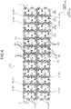
- the heat conductive sheet 51 when viewed from the height direction, is formed in a wave shape along outer peripheral surfaces of the battery cells 21a arranged in the depth direction in the battery modules 20. That is, the heat conductive sheet 51 is interposed between the battery modules 20 which are adjacent to each other, and is deformed in a wave shape along the shape of the outer peripheral surfaces of the battery cells 21a.
- the heat conductive sheet 51 includes a contact portion 51a and an extended portion 51b.
- the contact portion 51a is a portion that is in contact with the outer peripheral surfaces of the battery cells 21a of the battery modules 20 which are adjacent to each other in the width direction.
- the contact portion 51a extends from one end of the battery modules 20 to the other end thereof in the depth direction, and extends from an upper end of the battery modules 20 to a lower end of the battery modules 20 in the height direction. That is, when the battery modules 20 are viewed from the width direction, the contact portion 51a extends in a range corresponding to the entirety of an end surface of the battery modules 20 (refer to FIG. 2 ).
- the extended portion 51b extends from one end of the battery modules 20 to the other end thereof in the depth direction, and extends from a lower end of the battery modules 20 to the bottom portion 12a of the housing 10 in the height direction. In this manner, the extended portion 51b extends from a lower end of the battery modules 20 in the height direction to the bottom portion 12a of the housing 10. That is, the extended portion 51b extends from an end of the battery modules 20 on a side opposite to the bus bar 30 for modules to the bottom portion 12a of the housing 10. According to this, in the heat conductive sheet 51, it is possible to prevent the bus bar 30 for modules from interfering with the extended portion 51b. For example, as illustrated in FIG.
- the extended portion 51b in a state of being accommodated in the housing 10, the extended portion 51b is formed in an L-shape by bending an end of the extended portion 51b on the bottom portion 12a side of the housing 10.
- the L-shaped end In the extended portion 51b, the L-shaped end is in surface contact with the bottom portion 12a of the housing 10 (heat dissipation unit), and thus heat conduction from the heat conductive sheet 51 to the bottom portion 12a of the housing 10 is promoted, thereby enhancing heat dissipation effect.
- the heat dissipation unit 60 is a heat dissipating portion.
- the housing 10 also has a function of the heat dissipation unit 60.
- the housing 10 is connected to the extended portion 51b of the heat conductive sheet 51.
- the housing 10 has heat conductivity and is provided at a location that can come into contact with an outer heat medium such as external air. According to this, the housing 10 can dissipate heat of the battery cells 21a which is conducted through the heat conductive sheet 51.
- the battery modules 20 constitute a battery module group 40 in which the battery assemblies 21 are connected in series by the bus bar 22 for battery assemblies, and the battery modules 20 are connected in series by the bus bar 30 for modules.
- the battery module group 40 is accommodated in the inner space portion 11 of the housing 10.
- the battery module group 40 includes a holding member (not illustrated), and is held to the housing 10 by the holding member.
- twelve battery modules 20 are connected in series, and thus the battery module group 40 includes a total of 192 battery cells 21a.
- the battery pack 1 is mounted on a vehicle and the like in a state in which the battery module group 40 is held in the housing 10.
- the battery pack 1 includes the battery module group 40, the heat conductive member 50, and the heat dissipation unit 60.
- the battery module group 40 includes the plurality of battery modules 20 and the bus bar 30 for modules.
- the plurality of battery modules 20 include the plurality of battery assemblies 21 and the bus bar 22 for battery assemblies.
- the plurality of battery assemblies 21 include the plurality of battery cells 21a which are connected in parallel, are provided to be erected in the height direction in which a positive electrode and a negative electrode are opposite to each other, and are arranged in an even number in the depth direction orthogonal to the height direction.
- the bus bar 22 for battery assemblies connects the battery assemblies 21, which are adjacent to each other in the depth direction, in series.
- the bus bar 30 for modules connects the battery modules 20, which are adjacent to each other in the width direction among the plurality of battery modules 20 arranged in the width direction intersecting in the depth direction, in series.
- the heat conductive member 50 has heat conductivity, and is provided between the plurality of battery modules 20 which are adjacent to each other in the width direction.
- the heat dissipation unit 60 dissipates heat that is conducted to the heat conductive member 50.
- the bus bar 30 for modules is provided on one side of the battery modules 20 in the height direction.
- the heat conductive member 50 includes the contact portion 51a and the extended portion 51b.
- the contact portion 51a is in contact with the plurality of battery modules 20 which are adjacent to each other in the width direction.
- the extended portion 51b extends from a side of the battery modules 20 which is opposite to the bus bar 30 for modules in the height direction, and is connected to the heat dissipation unit 60.
- the heat conductive member 50 extends in the height direction, it is possible to dissipate heat of the battery assemblies 21 in a more uniform manner in comparison to a case where the heat conductive member extends in an arrangement direction (depth direction) of the plurality of battery assemblies 21 as in the related art.
- the heat conductive member 50 extends from a side opposite to the bus bar 30 for modules, it is possible to prevent the bus bar 30 for modules from interfering with the heat conductive member 50.
- the heat conductive member 50 that is formed in the same shape, and thus it is possible to uniformly dissipate heat of the battery assemblies 21 of the battery modules 20. As a result, in the battery pack 1, it is possible to appropriately dissipate heat of the battery assemblies 21.
- the battery pack 1 includes the housing 10 that has heat conductivity and accommodates the battery module group 40 and the heat conductive member 50.
- the extended portion 51b is in contact with an inner side of the housing 10.
- the housing 10 functions as the heat dissipation unit 60. According to this configuration, in the battery pack 1, heat of the battery cells 21a is conducted to the housing 10 through the extended portion 51b, and it is possible to dissipate heat conducted to the housing 10.
- the housing 10 is also allowed to function as the heat dissipation unit 60, and thus it is possible to simplify a configuration of the battery pack 1.
- the heat conductive member 50 includes the plurality of heat conductive sheets 51 which are formed in the same sheet shape, and each of the heat conductive sheets 51 is provided between the plurality of battery modules 20 which are adjacent to each other.
- the battery assemblies 21 are arranged in an odd number, and thus the bus bar 30 for modules is provided on an upper side and a lower side of the battery modules 20 in the height direction.
- the bus bar 30 for modules may interfere with the heat conductive sheets 51. In this case, it is necessary to provide a notch and the like in the heat conductive sheets 51, and thus shapes of the heat conductive sheets 51 are not the same as each other.
- the heat conductive sheets of the related art Accordingly, in the heat conductive sheets of the related art, a difference in heat conduction from the battery cells 21a occurs, and it is difficult to uniformly dissipate heat of the battery cells 21a.
- the heat conductive sheets of the related art it is necessary to prepare a plurality of the heat conductive sheets having shapes different from each other, and thus there is a problem that management of part numbers of the heat conductive sheets becomes complicate.
- the bus bar 30 for modules is provided on one side of the battery modules 20 in the height direction, and thus the heat conductive sheets 51 can be formed in the same shape. According to this, in the battery pack 1, it is possible to uniformly dissipate heat of the battery cells 21a, and it is possible to easily manage part numbers of the heat conductive sheets 51.
- the plurality of battery cells 21a are arranged in two rows in the depth direction. According to this configuration, in the battery pack 1, the heat conductive sheet 51 can come into contact with the entirety of the battery cells 21a, and it is possible to effectively dissipate heat of the battery cells 21a.
- the bus bar 30 for modules include the first bus bar piece 31 that is provided in a battery module 20 on one side between the battery modules 20 which are adjacent to each other, and the second bus bar piece 32 that is provided in a battery module 20 on the other side and is different from the first bus bar piece 31, and the connection portion 33 that connects the first bus bar piece 31 and the second bus bar piece 32.
- the battery assemblies 21 are connected to each other by the bus bar 22 for battery assemblies, and it is possible to form individual battery modules 20 which are subdivided from the entirety of the battery modules 20 (battery module group 40).
- the entirety of the battery assemblies 21 are connected through resistance welding.
- the battery assemblies 21 are connected through resistance welding in a unit of the battery module 20. Accordingly, even when welding failure occurs in the resistance welding in the course of the resistance welding, the battery cells 21a (for example, sixteen pieces) corresponding to one battery module 20 to the maximum may be discarded, and thus it is possible to further suppress the manufacturing loss in comparison to the battery pack of the related art.
- the first bus bar piece 31 and the second bus bar piece 32 are welded with a laser to connect the battery modules 20 to each other, and thus even when the welding failure occurs in the laser welding, it is possible to attempt the laser welding again, and thus it is also possible to suppress the battery modules 20 from being discarded.
- the entirety of a plurality of the bus bar 30 for modules are provided on an upper side of the battery modules 20 in the height direction, and thus it is possible to weld the entirety of a plurality of the first bus bar pieces 31 and a plurality of the second bus bar pieces 32 with a laser from an upper side in the height direction. As a result, it is possible to improve workability.
- total positive electrodes P and total negative electrodes N which are connected to a load unit (not illustrated) that supplies electric power, can be located on one side (for example, an upper side) in the height direction, and thus it is possible to improve workability of wiring connection to the load unit.
- the bus bar 30 for modules which includes the connection portion 33 that connects the first bus bar piece 31 and the second bus bar piece 32, but there is no limitation thereto.
- the bus bar 30 for modules may be configured as one sheet of flat plate-shaped bus bar that does not include the connection portion 33. That is, the bus bar 30 for modules may be configured as one sheet of flat plate-shaped bus bar that does not include joining surfaces for joining bus bars different from each other.
- the contact portion 51a of the heat conductive sheets 51 extends from one end of the battery modules 20 to the other end thereof in the depth direction, but there is no limitation thereto.
- the contact portion 51a may extend only to the central portion excluding both ends of the battery modules 20 in the depth direction.
- the contact portion 51a may extend in a range excluding the battery cells 21a on both ends of the battery modules 20 in the depth direction. The reason for this is because a temperature of the battery cells 21a on both ends of the battery modules 20 may be lower in comparison to the battery cells 21a at the central portion, and thus the heat conductive sheets 51 may not be used.
- the extended portion 51b is in contact with the bottom portion 12a of the housing 10 to dissipate heat, but there is no limitation thereto.
- the extended portion 51b may be immersed in a flowable member stored in the bottom portion 12a of the housing 10 to dissipate heat.
- the flowable member is a liquid having flowability, heat conductivity, and a heat accumulation property. Examples of the liquid having the flowability, the heat conductivity, and the heat accumulation property include water, oils such as silicon oil, ethylene glycol, glycerin, acetone, brine, and the like.
- the plurality of battery cells 21a are arranged in two rows in the depth direction, but there is no limitation thereto.
- the plurality of battery cells 21a may be arranged in three rows.
- connection portion 33 includes a solidification portion 33a that is melted by using laser light as a heat source and is solidified, but there is no limitation thereto.
- the connection portion 33 may be provided with a screw fastening unit that includes a nut having a fastening opening, and a bolt inserted into the opening and is fastened to the nut.
- the connection portion 33 may include a connector connection portion including a male connector provided with a first terminal, and a female connector provided with a second terminal that is fitted around the male connector and is electrically connected to the first terminal.
- the number of the battery cells 21a of each of the battery assemblies 21 may be two or greater without limitation to four.
- the number of the terminals 22b of the bus bar 22 for battery assemblies is appropriately changed in correspondence with the number of the battery cells 21a of each of the battery assemblies 21.
- the number of the terminals 31b and 32b of the bus bar 30 for modules is appropriately changed in correspondence with the number of the battery cells 21a of the battery assembly 21.
- the number of the battery assemblies 21 of the battery module 20 may be an even number of two or greater without limitation to four.
- the heat conductive member since the heat conductive member includes the extended portion that extends in the height direction from a side opposite to the bus bar for modules of the battery module, and is connected to the heat dissipation unit, it is possible to prevent the bus bar for modules from interfering the heat conductive member, and thus it is possible to appropriately dissipate heat of the battery body.
Landscapes
- Chemical & Material Sciences (AREA)
- Chemical Kinetics & Catalysis (AREA)
- Electrochemistry (AREA)
- General Chemical & Material Sciences (AREA)
- Engineering & Computer Science (AREA)
- Manufacturing & Machinery (AREA)
- Secondary Cells (AREA)
- Battery Mounting, Suspending (AREA)
- Connection Of Batteries Or Terminals (AREA)
- Sealing Battery Cases Or Jackets (AREA)
Applications Claiming Priority (1)
| Application Number | Priority Date | Filing Date | Title |
|---|---|---|---|
| JP2018049451A JP6976890B2 (ja) | 2018-03-16 | 2018-03-16 | 電池パック |
Publications (2)
| Publication Number | Publication Date |
|---|---|
| EP3540820A1 true EP3540820A1 (fr) | 2019-09-18 |
| EP3540820B1 EP3540820B1 (fr) | 2022-06-29 |
Family
ID=65724236
Family Applications (1)
| Application Number | Title | Priority Date | Filing Date |
|---|---|---|---|
| EP19161221.7A Active EP3540820B1 (fr) | 2018-03-16 | 2019-03-07 | Bloc-batterie |
Country Status (4)
| Country | Link |
|---|---|
| US (1) | US11018386B2 (fr) |
| EP (1) | EP3540820B1 (fr) |
| JP (1) | JP6976890B2 (fr) |
| CN (1) | CN110277519B (fr) |
Families Citing this family (1)
| Publication number | Priority date | Publication date | Assignee | Title |
|---|---|---|---|---|
| GB2590615B (en) * | 2019-12-19 | 2024-05-29 | Dyson Technology Ltd | Battery module and battery pack |
Citations (4)
| Publication number | Priority date | Publication date | Assignee | Title |
|---|---|---|---|---|
| JP2002373708A (ja) | 2001-06-15 | 2002-12-26 | Hitachi Koki Co Ltd | 電池パック |
| EP2031672A1 (fr) * | 2007-08-27 | 2009-03-04 | Toyoda Gosei Co., Ltd. | Ensemble de batterie |
| US20090297892A1 (en) * | 2008-04-14 | 2009-12-03 | A123 Systems, Inc. | Flexible Voltage Nested Battery Module Design |
| FR2963486A1 (fr) * | 2010-07-29 | 2012-02-03 | E4V | Systeme de refroidissement de batterie electrique |
Family Cites Families (23)
| Publication number | Priority date | Publication date | Assignee | Title |
|---|---|---|---|---|
| JP4025928B2 (ja) * | 1995-02-17 | 2007-12-26 | 株式会社ジーエス・ユアサコーポレーション | 円筒型電池及び組電池 |
| US6087036A (en) * | 1997-07-25 | 2000-07-11 | 3M Innovative Properties Company | Thermal management system and method for a solid-state energy storing device |
| JPH11213976A (ja) * | 1998-01-21 | 1999-08-06 | Nissan Motor Co Ltd | 電気自動車のバッテリ固定構造およびバッテリ冷却方法 |
| US20070009787A1 (en) * | 2005-05-12 | 2007-01-11 | Straubel Jeffrey B | Method and apparatus for mounting, cooling, connecting and protecting batteries |
| CN102257652B (zh) * | 2008-11-12 | 2014-04-02 | 江森自控帅福得先进能源动力系统有限责任公司 | 具有热交换器的电池系统 |
| US8288035B2 (en) * | 2009-01-09 | 2012-10-16 | Electrochem Solutions, Inc. | Modular battery pack |
| DE102009043443A1 (de) * | 2009-09-29 | 2011-03-31 | Volkswagen Ag | Verfahren zur Kühlung eines Batteriemoduls und Batteriemodul für ein Fahrzeug |
| WO2011052699A1 (fr) * | 2009-10-28 | 2011-05-05 | 矢崎総業株式会社 | Barre omnibus pour la connexion de pôles de batterie, et dispositif de contrôle de tension de batterie l'utilisant |
| JP5343048B2 (ja) * | 2010-07-29 | 2013-11-13 | 日立ビークルエナジー株式会社 | 蓄電モジュールおよび蓄電装置 |
| ES2621135T3 (es) * | 2010-07-29 | 2017-07-03 | E4V | Sistema de refrigeración de batería eléctrica y batería que comprende dicho sistema |
| KR20130003390U (ko) * | 2010-10-01 | 2013-06-07 | 그라프텍 인터내셔널 홀딩스 인코포레이티드 | 전지 팩용 열 관리 구조물 |
| US9088031B2 (en) * | 2010-11-05 | 2015-07-21 | Panasonic Intellectual Property Management Co., Ltd. | Battery module |
| CN102208573B (zh) * | 2011-04-22 | 2013-07-31 | 东风汽车公司 | 动力电池组排列连接组装结构 |
| JP2014191968A (ja) * | 2013-03-27 | 2014-10-06 | Toyoda Gosei Co Ltd | 電池装置 |
| KR101749509B1 (ko) * | 2013-09-13 | 2017-06-21 | 삼성에스디아이 주식회사 | 용접부를 포함하는 배터리 팩 |
| CN204361163U (zh) * | 2014-12-23 | 2015-05-27 | 比亚迪股份有限公司 | 一种电池连接片、电池组、电池包和电动汽车 |
| DE102015013377A1 (de) * | 2015-10-18 | 2017-04-20 | Kreisel Electric GmbH | Temperiereinrichtung für ein Batteriesystem |
| US11128012B2 (en) * | 2016-06-29 | 2021-09-21 | Panasonic Intellectual Property Management Co., Ltd. | Battery module including thermal insulator disposed between battery blocks |
| JP6929623B2 (ja) * | 2016-08-29 | 2021-09-01 | 矢崎総業株式会社 | 車両用電池パック |
| CN106207072B (zh) * | 2016-09-14 | 2018-11-13 | 恒大法拉第未来智能汽车(广东)有限公司 | 电池组极耳冷却结构、电池组以及具有该电池组的车辆 |
| CN206992176U (zh) * | 2017-05-17 | 2018-02-09 | 东莞市联洲知识产权运营管理有限公司 | 一种应用于新能源汽车电池的散热外壳 |
| CN206893674U (zh) * | 2017-06-30 | 2018-01-16 | 东莞市沃泰通新能源有限公司 | 一种散热电池箱 |
| US10847760B2 (en) * | 2017-11-13 | 2020-11-24 | Lg Chem, Ltd. | Battery module having heat pipe and battery pack including the same |
-
2018
- 2018-03-16 JP JP2018049451A patent/JP6976890B2/ja active Active
-
2019
- 2019-03-07 EP EP19161221.7A patent/EP3540820B1/fr active Active
- 2019-03-12 US US16/351,427 patent/US11018386B2/en active Active
- 2019-03-14 CN CN201910194418.3A patent/CN110277519B/zh active Active
Patent Citations (4)
| Publication number | Priority date | Publication date | Assignee | Title |
|---|---|---|---|---|
| JP2002373708A (ja) | 2001-06-15 | 2002-12-26 | Hitachi Koki Co Ltd | 電池パック |
| EP2031672A1 (fr) * | 2007-08-27 | 2009-03-04 | Toyoda Gosei Co., Ltd. | Ensemble de batterie |
| US20090297892A1 (en) * | 2008-04-14 | 2009-12-03 | A123 Systems, Inc. | Flexible Voltage Nested Battery Module Design |
| FR2963486A1 (fr) * | 2010-07-29 | 2012-02-03 | E4V | Systeme de refroidissement de batterie electrique |
Also Published As
| Publication number | Publication date |
|---|---|
| JP6976890B2 (ja) | 2021-12-08 |
| CN110277519A (zh) | 2019-09-24 |
| JP2019160732A (ja) | 2019-09-19 |
| US11018386B2 (en) | 2021-05-25 |
| CN110277519B (zh) | 2021-12-21 |
| US20190288356A1 (en) | 2019-09-19 |
| EP3540820B1 (fr) | 2022-06-29 |
Similar Documents
| Publication | Publication Date | Title |
|---|---|---|
| CN110710051B (zh) | 电池组 | |
| CN107369863B (zh) | 子组件和具有该子组件的电池组件 | |
| KR101509474B1 (ko) | 단일 전극단자 결합부를 가진 전지 조합체 | |
| EP2654101B1 (fr) | Bloc-batteries | |
| KR102059077B1 (ko) | 배터리 모듈 및 이를 포함하는 배터리 팩, 자동차 | |
| US20180151862A1 (en) | Power supply device and bus bar for battery cell | |
| KR102619201B1 (ko) | 이차 전지 및 이를 포함한 배터리 모듈 | |
| KR20170053429A (ko) | 내충격성이 향상된 배터리 모듈 | |
| KR20180131602A (ko) | 에너지 저장 디바이스를 위한 냉각 장치 | |
| US9786879B2 (en) | Battery module | |
| KR102589964B1 (ko) | 전지 팩 커넥터 및 이를 포함하는 전지 팩 | |
| JP6715942B2 (ja) | 電池モジュール、及び電池パック | |
| EP3540819B1 (fr) | Bloc-batterie | |
| US11018386B2 (en) | Battery pack | |
| US11984612B2 (en) | Battery module comprising module housing | |
| KR101717199B1 (ko) | 전압 센싱용 접속 돌기부가 형성되어 있는 전지셀 및 이를 포함하는 전지모듈 | |
| JP2022545245A (ja) | 電池モジュール | |
| JP2011129310A (ja) | 電池モジュール | |
| JP2020155340A (ja) | 車載用バッテリ | |
| JP2024501574A (ja) | バッテリーモジュール、該バッテリーモジュールを含むバッテリーパック及び該バッテリーパックを含む自動車 | |
| CN116057773A (zh) | 包括多个并联电池单元的电池模块 | |
| TW201826589A (zh) | 電池組 |
Legal Events
| Date | Code | Title | Description |
|---|---|---|---|
| PUAI | Public reference made under article 153(3) epc to a published international application that has entered the european phase |
Free format text: ORIGINAL CODE: 0009012 |
|
| STAA | Information on the status of an ep patent application or granted ep patent |
Free format text: STATUS: REQUEST FOR EXAMINATION WAS MADE |
|
| 17P | Request for examination filed |
Effective date: 20190307 |
|
| AK | Designated contracting states |
Kind code of ref document: A1 Designated state(s): AL AT BE BG CH CY CZ DE DK EE ES FI FR GB GR HR HU IE IS IT LI LT LU LV MC MK MT NL NO PL PT RO RS SE SI SK SM TR |
|
| AX | Request for extension of the european patent |
Extension state: BA ME |
|
| RBV | Designated contracting states (corrected) |
Designated state(s): AL AT BE BG CH CY CZ DE DK EE ES FI FR GB GR HR HU IE IS IT LI LT LU LV MC MK MT NL NO PL PT RO RS SE SI SK SM TR |
|
| STAA | Information on the status of an ep patent application or granted ep patent |
Free format text: STATUS: EXAMINATION IS IN PROGRESS |
|
| 17Q | First examination report despatched |
Effective date: 20220104 |
|
| REG | Reference to a national code |
Ref country code: DE Ref legal event code: R079 Ref document number: 602019016303 Country of ref document: DE Free format text: PREVIOUS MAIN CLASS: H01M0002200000 Ipc: H01M0010655100 |
|
| GRAP | Despatch of communication of intention to grant a patent |
Free format text: ORIGINAL CODE: EPIDOSNIGR1 |
|
| STAA | Information on the status of an ep patent application or granted ep patent |
Free format text: STATUS: GRANT OF PATENT IS INTENDED |
|
| RIC1 | Information provided on ipc code assigned before grant |
Ipc: H01M 50/502 20210101ALI20220322BHEP Ipc: H01M 10/655 20140101ALI20220322BHEP Ipc: H01M 10/6555 20140101ALI20220322BHEP Ipc: H01M 10/6551 20140101AFI20220322BHEP |
|
| INTG | Intention to grant announced |
Effective date: 20220421 |
|
| GRAS | Grant fee paid |
Free format text: ORIGINAL CODE: EPIDOSNIGR3 |
|
| GRAA | (expected) grant |
Free format text: ORIGINAL CODE: 0009210 |
|
| STAA | Information on the status of an ep patent application or granted ep patent |
Free format text: STATUS: THE PATENT HAS BEEN GRANTED |
|
| AK | Designated contracting states |
Kind code of ref document: B1 Designated state(s): AL AT BE BG CH CY CZ DE DK EE ES FI FR GB GR HR HU IE IS IT LI LT LU LV MC MK MT NL NO PL PT RO RS SE SI SK SM TR |
|
| REG | Reference to a national code |
Ref country code: CH Ref legal event code: EP |
|
| REG | Reference to a national code |
Ref country code: AT Ref legal event code: REF Ref document number: 1501922 Country of ref document: AT Kind code of ref document: T Effective date: 20220715 |
|
| REG | Reference to a national code |
Ref country code: IE Ref legal event code: FG4D |
|
| REG | Reference to a national code |
Ref country code: DE Ref legal event code: R096 Ref document number: 602019016303 Country of ref document: DE |
|
| REG | Reference to a national code |
Ref country code: LT Ref legal event code: MG9D |
|
| PG25 | Lapsed in a contracting state [announced via postgrant information from national office to epo] |
Ref country code: SE Free format text: LAPSE BECAUSE OF FAILURE TO SUBMIT A TRANSLATION OF THE DESCRIPTION OR TO PAY THE FEE WITHIN THE PRESCRIBED TIME-LIMIT Effective date: 20220629 Ref country code: NO Free format text: LAPSE BECAUSE OF FAILURE TO SUBMIT A TRANSLATION OF THE DESCRIPTION OR TO PAY THE FEE WITHIN THE PRESCRIBED TIME-LIMIT Effective date: 20220929 Ref country code: LT Free format text: LAPSE BECAUSE OF FAILURE TO SUBMIT A TRANSLATION OF THE DESCRIPTION OR TO PAY THE FEE WITHIN THE PRESCRIBED TIME-LIMIT Effective date: 20220629 Ref country code: HR Free format text: LAPSE BECAUSE OF FAILURE TO SUBMIT A TRANSLATION OF THE DESCRIPTION OR TO PAY THE FEE WITHIN THE PRESCRIBED TIME-LIMIT Effective date: 20220629 Ref country code: GR Free format text: LAPSE BECAUSE OF FAILURE TO SUBMIT A TRANSLATION OF THE DESCRIPTION OR TO PAY THE FEE WITHIN THE PRESCRIBED TIME-LIMIT Effective date: 20220930 Ref country code: FI Free format text: LAPSE BECAUSE OF FAILURE TO SUBMIT A TRANSLATION OF THE DESCRIPTION OR TO PAY THE FEE WITHIN THE PRESCRIBED TIME-LIMIT Effective date: 20220629 Ref country code: BG Free format text: LAPSE BECAUSE OF FAILURE TO SUBMIT A TRANSLATION OF THE DESCRIPTION OR TO PAY THE FEE WITHIN THE PRESCRIBED TIME-LIMIT Effective date: 20220929 |
|
| REG | Reference to a national code |
Ref country code: NL Ref legal event code: MP Effective date: 20220629 |
|
| REG | Reference to a national code |
Ref country code: AT Ref legal event code: MK05 Ref document number: 1501922 Country of ref document: AT Kind code of ref document: T Effective date: 20220629 |
|
| PG25 | Lapsed in a contracting state [announced via postgrant information from national office to epo] |
Ref country code: RS Free format text: LAPSE BECAUSE OF FAILURE TO SUBMIT A TRANSLATION OF THE DESCRIPTION OR TO PAY THE FEE WITHIN THE PRESCRIBED TIME-LIMIT Effective date: 20220629 Ref country code: LV Free format text: LAPSE BECAUSE OF FAILURE TO SUBMIT A TRANSLATION OF THE DESCRIPTION OR TO PAY THE FEE WITHIN THE PRESCRIBED TIME-LIMIT Effective date: 20220629 |
|
| PG25 | Lapsed in a contracting state [announced via postgrant information from national office to epo] |
Ref country code: NL Free format text: LAPSE BECAUSE OF FAILURE TO SUBMIT A TRANSLATION OF THE DESCRIPTION OR TO PAY THE FEE WITHIN THE PRESCRIBED TIME-LIMIT Effective date: 20220629 |
|
| PG25 | Lapsed in a contracting state [announced via postgrant information from national office to epo] |
Ref country code: SM Free format text: LAPSE BECAUSE OF FAILURE TO SUBMIT A TRANSLATION OF THE DESCRIPTION OR TO PAY THE FEE WITHIN THE PRESCRIBED TIME-LIMIT Effective date: 20220629 Ref country code: SK Free format text: LAPSE BECAUSE OF FAILURE TO SUBMIT A TRANSLATION OF THE DESCRIPTION OR TO PAY THE FEE WITHIN THE PRESCRIBED TIME-LIMIT Effective date: 20220629 Ref country code: RO Free format text: LAPSE BECAUSE OF FAILURE TO SUBMIT A TRANSLATION OF THE DESCRIPTION OR TO PAY THE FEE WITHIN THE PRESCRIBED TIME-LIMIT Effective date: 20220629 Ref country code: PT Free format text: LAPSE BECAUSE OF FAILURE TO SUBMIT A TRANSLATION OF THE DESCRIPTION OR TO PAY THE FEE WITHIN THE PRESCRIBED TIME-LIMIT Effective date: 20221031 Ref country code: ES Free format text: LAPSE BECAUSE OF FAILURE TO SUBMIT A TRANSLATION OF THE DESCRIPTION OR TO PAY THE FEE WITHIN THE PRESCRIBED TIME-LIMIT Effective date: 20220629 Ref country code: EE Free format text: LAPSE BECAUSE OF FAILURE TO SUBMIT A TRANSLATION OF THE DESCRIPTION OR TO PAY THE FEE WITHIN THE PRESCRIBED TIME-LIMIT Effective date: 20220629 Ref country code: AT Free format text: LAPSE BECAUSE OF FAILURE TO SUBMIT A TRANSLATION OF THE DESCRIPTION OR TO PAY THE FEE WITHIN THE PRESCRIBED TIME-LIMIT Effective date: 20220629 |
|
| PG25 | Lapsed in a contracting state [announced via postgrant information from national office to epo] |
Ref country code: PL Free format text: LAPSE BECAUSE OF FAILURE TO SUBMIT A TRANSLATION OF THE DESCRIPTION OR TO PAY THE FEE WITHIN THE PRESCRIBED TIME-LIMIT Effective date: 20220629 Ref country code: IS Free format text: LAPSE BECAUSE OF FAILURE TO SUBMIT A TRANSLATION OF THE DESCRIPTION OR TO PAY THE FEE WITHIN THE PRESCRIBED TIME-LIMIT Effective date: 20221029 |
|
| REG | Reference to a national code |
Ref country code: DE Ref legal event code: R097 Ref document number: 602019016303 Country of ref document: DE |
|
| PG25 | Lapsed in a contracting state [announced via postgrant information from national office to epo] |
Ref country code: AL Free format text: LAPSE BECAUSE OF FAILURE TO SUBMIT A TRANSLATION OF THE DESCRIPTION OR TO PAY THE FEE WITHIN THE PRESCRIBED TIME-LIMIT Effective date: 20220629 |
|
| PG25 | Lapsed in a contracting state [announced via postgrant information from national office to epo] |
Ref country code: DK Free format text: LAPSE BECAUSE OF FAILURE TO SUBMIT A TRANSLATION OF THE DESCRIPTION OR TO PAY THE FEE WITHIN THE PRESCRIBED TIME-LIMIT Effective date: 20220629 Ref country code: CZ Free format text: LAPSE BECAUSE OF FAILURE TO SUBMIT A TRANSLATION OF THE DESCRIPTION OR TO PAY THE FEE WITHIN THE PRESCRIBED TIME-LIMIT Effective date: 20220629 |
|
| PLBE | No opposition filed within time limit |
Free format text: ORIGINAL CODE: 0009261 |
|
| STAA | Information on the status of an ep patent application or granted ep patent |
Free format text: STATUS: NO OPPOSITION FILED WITHIN TIME LIMIT |
|
| 26N | No opposition filed |
Effective date: 20230330 |
|
| PG25 | Lapsed in a contracting state [announced via postgrant information from national office to epo] |
Ref country code: SI Free format text: LAPSE BECAUSE OF FAILURE TO SUBMIT A TRANSLATION OF THE DESCRIPTION OR TO PAY THE FEE WITHIN THE PRESCRIBED TIME-LIMIT Effective date: 20220629 |
|
| PG25 | Lapsed in a contracting state [announced via postgrant information from national office to epo] |
Ref country code: MC Free format text: LAPSE BECAUSE OF FAILURE TO SUBMIT A TRANSLATION OF THE DESCRIPTION OR TO PAY THE FEE WITHIN THE PRESCRIBED TIME-LIMIT Effective date: 20220629 |
|
| REG | Reference to a national code |
Ref country code: CH Ref legal event code: PL |
|
| GBPC | Gb: european patent ceased through non-payment of renewal fee |
Effective date: 20230307 |
|
| REG | Reference to a national code |
Ref country code: BE Ref legal event code: MM Effective date: 20230331 |
|
| PG25 | Lapsed in a contracting state [announced via postgrant information from national office to epo] |
Ref country code: LU Free format text: LAPSE BECAUSE OF NON-PAYMENT OF DUE FEES Effective date: 20230307 |
|
| REG | Reference to a national code |
Ref country code: IE Ref legal event code: MM4A |
|
| PG25 | Lapsed in a contracting state [announced via postgrant information from national office to epo] |
Ref country code: GB Free format text: LAPSE BECAUSE OF NON-PAYMENT OF DUE FEES Effective date: 20230307 |
|
| PG25 | Lapsed in a contracting state [announced via postgrant information from national office to epo] |
Ref country code: LI Free format text: LAPSE BECAUSE OF NON-PAYMENT OF DUE FEES Effective date: 20230331 Ref country code: IT Free format text: LAPSE BECAUSE OF FAILURE TO SUBMIT A TRANSLATION OF THE DESCRIPTION OR TO PAY THE FEE WITHIN THE PRESCRIBED TIME-LIMIT Effective date: 20220629 Ref country code: IE Free format text: LAPSE BECAUSE OF NON-PAYMENT OF DUE FEES Effective date: 20230307 Ref country code: GB Free format text: LAPSE BECAUSE OF NON-PAYMENT OF DUE FEES Effective date: 20230307 Ref country code: FR Free format text: LAPSE BECAUSE OF NON-PAYMENT OF DUE FEES Effective date: 20230331 Ref country code: CH Free format text: LAPSE BECAUSE OF NON-PAYMENT OF DUE FEES Effective date: 20230331 |
|
| PG25 | Lapsed in a contracting state [announced via postgrant information from national office to epo] |
Ref country code: BE Free format text: LAPSE BECAUSE OF NON-PAYMENT OF DUE FEES Effective date: 20230331 |
|
| PGFP | Annual fee paid to national office [announced via postgrant information from national office to epo] |
Ref country code: DE Payment date: 20240130 Year of fee payment: 6 |