EP3540135A1 - Montagesatz für in einer gebäudewand zu montierendes element - Google Patents
Montagesatz für in einer gebäudewand zu montierendes element Download PDFInfo
- Publication number
- EP3540135A1 EP3540135A1 EP18161484.3A EP18161484A EP3540135A1 EP 3540135 A1 EP3540135 A1 EP 3540135A1 EP 18161484 A EP18161484 A EP 18161484A EP 3540135 A1 EP3540135 A1 EP 3540135A1
- Authority
- EP
- European Patent Office
- Prior art keywords
- mounting
- wall
- assembly
- aid
- receptacle
- Prior art date
- Legal status (The legal status is an assumption and is not a legal conclusion. Google has not performed a legal analysis and makes no representation as to the accuracy of the status listed.)
- Granted
Links
Images
Classifications
-
- E—FIXED CONSTRUCTIONS
- E03—WATER SUPPLY; SEWERAGE
- E03D—WATER-CLOSETS OR URINALS WITH FLUSHING DEVICES; FLUSHING VALVES THEREFOR
- E03D11/00—Other component parts of water-closets, e.g. noise-reducing means in the flushing system, flushing pipes mounted in the bowl, seals for the bowl outlet, devices preventing overflow of the bowl contents; devices forming a water seal in the bowl after flushing, devices eliminating obstructions in the bowl outlet or preventing backflow of water and excrements from the waterpipe
- E03D11/13—Parts or details of bowls; Special adaptations of pipe joints or couplings for use with bowls, e.g. provisions in bowl construction preventing backflow of waste-water from the bowl in the flushing pipe or cistern, provisions for a secondary flushing, for noise-reducing
- E03D11/14—Means for connecting the bowl to the wall, e.g. to a wall outlet
- E03D11/143—Mounting frames for toilets and urinals
- E03D11/146—Mounting frames for toilets and urinals with incorporated cistern
-
- E—FIXED CONSTRUCTIONS
- E03—WATER SUPPLY; SEWERAGE
- E03D—WATER-CLOSETS OR URINALS WITH FLUSHING DEVICES; FLUSHING VALVES THEREFOR
- E03D1/00—Water flushing devices with cisterns ; Setting up a range of flushing devices or water-closets; Combinations of several flushing devices
- E03D1/01—Shape or selection of material for flushing cisterns
- E03D1/012—Details of shape of cisterns, e.g. for connecting to wall, for supporting or connecting flushing-device actuators
- E03D1/0125—Details of shape of cisterns, e.g. for connecting to wall, for supporting or connecting flushing-device actuators of built-in cisterns
-
- E—FIXED CONSTRUCTIONS
- E04—BUILDING
- E04F—FINISHING WORK ON BUILDINGS, e.g. STAIRS, FLOORS
- E04F19/00—Other details of constructional parts for finishing work on buildings
- E04F19/08—Built-in cupboards; Masks of niches; Covers of holes enabling access to installations
-
- E—FIXED CONSTRUCTIONS
- E03—WATER SUPPLY; SEWERAGE
- E03C—DOMESTIC PLUMBING INSTALLATIONS FOR FRESH WATER OR WASTE WATER; SINKS
- E03C1/00—Domestic plumbing installations for fresh water or waste water; Sinks
- E03C1/01—Domestic plumbing installations for fresh water or waste water; Sinks for combinations of baths, showers, sinks, wash-basins, closets, urinals, or the like
-
- E—FIXED CONSTRUCTIONS
- E03—WATER SUPPLY; SEWERAGE
- E03D—WATER-CLOSETS OR URINALS WITH FLUSHING DEVICES; FLUSHING VALVES THEREFOR
- E03D1/00—Water flushing devices with cisterns ; Setting up a range of flushing devices or water-closets; Combinations of several flushing devices
- E03D1/006—Realisations of and provisions for preventing "sweating" of cisterns
Definitions
- the present invention relates to a mounting kit with which an element can be mounted in a building wall.
- Said box could also be a leakage protection device for a water dispenser, such as a cistern, a valve or a valve or part of a wall drain for z. B. shower water. It can be z. B. also be closed by doors furniture-like element, for. B. a mirror cabinet.
- a water dispenser such as a cistern, a valve or a valve or part of a wall drain for z. B. shower water. It can be z. B. also be closed by doors furniture-like element, for. B. a mirror cabinet.
- ⁇ For mounting objects on or in walls various mounting devices are known, in the simplest case nails and screws for hanging or screwing, but also z. B. to be fastened to a wall rail systems for system shelf elements.
- a wall such as a drywall or a pretext in a bathroom
- mounting racks in common use, with which z. B. WCs or washbasins can be freely suspended, hanging in the mounted state on the one hand in front of the wall and on the other hand anchored in the wall.
- This mounting racks are basically made of stabilized by cross struts vertical supports that derive the corresponding forces down to the ground and on which a sanitary object is in turn screwed.
- the prior art mounting racks are covered by wall panels, preferably first a panel with wall panels (drywall elements) and then followed by further steps. For example. For example, a waterproofing layer and then a paneling with bathroom tiles, natural stone slabs or other wall designs may be applied.
- the invention has for its object to provide an advantageous in terms of mounting an element in a building wall mounting kit.
- a mounting set of an element to be mounted in a building wall and a mounting aid for mounting the element in the building wall by mounting the mounting aid in the building wall and mounting the element in the mounting aid, which mounting aid has plate elements, which in the mounted state define an outer contour of a surface requirement of the element to be assembled from horizontal and vertical boundary lines in a wall-parallel plane and which in the mounted state in a depth direction perpendicular to the wall-parallel plane have at least the depth of the element to be mounted in this depth direction, and by an advantageous use of the mounting kit and its elements.
- a set of the element to be mounted and an associated auxiliary assembly device is provided.
- the assembly aid serves to prepare for assembly and as a means of assembly.
- the elements to be mounted is in fact mounted after installation of the auxiliary assembly device in the wall in the correspondingly designed auxiliary assembly device, the auxiliary assembly device mounted as the first. It is designed so that it even before the later installation of the element itself marks the required space in the wall. It thus serves to keep free and to prevent other devices are installed unintentionally or due to lack of coordination between different trades in the space provided for the element volume when this is due to be assembled.
- plate elements of the assembly aid on the one hand define the horizontal and vertical boundary lines in that the plate elements with their plates, ie their flat parts, at least embody a part of the corresponding lines.
- the plate elements should have the required depth and thus clarify.
- the assembly aid thus provides a mounting means and at the same time a placeholder.
- the plate elements are provided in the form of elbows for the corners of a rectangle formed from the vertical and horizontal boundary lines, so that each one leg of each elbow in the mounted state horizontally and the other is vertical and the horizontal legs of pairs of elbows with each other the horizontal boundary lines and Similarly, the vertical legs of (differently formed) pairs of elbows form the vertical boundary lines. You may be able to leave a gap between the legs, which will be discussed in more detail.
- a further preferred embodiment provides that the plate elements protrude so far in the depth direction in the mounted state that it results in a limitation in the cladding of the wall with wall cladding panels, for example drywall panel panels.
- wall cladding panels for example drywall panel panels.
- These can be applied in horizontal or vertical direction to the wall cladding panels.
- wall cladding panels are generally limited by horizontal and vertical edges, and these boundary edges play an essential role in the cladding, because they allow the panels to abut against each other or from panels to one end of the wall (eg the floor or ceiling or a wall) already existing other wall) and thus also determine desired recesses in the wall paneling.
- the cladding panels can also be cut to size before they are accordingly brought into abutment with the assembly aid; but the assembly aid is to serve to keep free from the beginning when disguising a desired recess for the subsequent assembly of the element and not have to cut it later from already attached cladding panels.
- the elbows can then z. B. are each mounted on a vertical support of a mounting frame or other support means in the wall. If z. B. between two horizontally adjacent such elbows remains a free distance which is smaller than the typical size of a wall cladding panel, such a plate can be applied with a horizontal boundary edge to both elbows.
- gaps between the parts of the auxiliary installation device defining the area requirement, such as the angle pieces each amount to at most 50% of the respective length of the outer contour to be kept clear.
- the respective leg lengths of the angle pieces together preferably amount to at least 50% of the distance between the actual corners defined by the angle pieces.
- the angle pieces or other parts of the assembly aid usually provide sufficient contact surface for wall cladding panels. Preferred lower limits are 60%, 70% and 80%.
- leg of elbows is accordingly also considered to divide a distance therebetween by one or a plurality of individual parts, such as tabs, which in turn can serve as an attachment.
- the described angle pieces or other parts can in principle be mounted independently or z. B. be connected in pairs.
- the mounting aid has a peripheral frame, so that the outer contour of the space requirement defining parts held together and can be mounted together.
- the frame is open for mounting the element to be mounted in the building wall and designed to cover it in the assembled state.
- the plate elements with respect to the horizontal direction in the wall plane can define a smaller distance from each other than area required as the distance in the wall predetermined vertical supports from each other.
- the assembly aid according to the invention has contact surfaces for mounting on these vertical Supports which are spaced horizontally from the plate members to the outside and z. B. can be screwed to the supports. In the exemplary embodiment that applies top right and left.
- a further preferred embodiment relates to at least one wall-parallel abutment surface of the auxiliary assembly device, which is provided in addition to the plate elements and serves to fasten the element to be mounted.
- These can by the element and by a wall panel, z. B. a typical panel plate drywall, and finally be passed through said wall-parallel contact surface bolts, especially screws.
- self-tapping screws can penetrate into the wall-parallel abutment surface and intersect a mating thread there in order to improve the retention of the screws (as opposed to screwing them only into the panel plates).
- the element to be mounted is preferably a Wandeinbaubox, z. B. may have a furniture-like function or simply a shelf. It is preferably closed apart from a front opening, moreover. Other options have already been mentioned at the very beginning.
- the element to be mounted can be fastened by means of a mounting device designated here as a form-locking device.
- the form-locking device has a receptacle on the element or the auxiliary assembly device on the one hand and on the other hand, a projection on the mounting auxiliary device or the element for engaging in the recording, both of which can be clamped by a clamping device against each other.
- the projection can be introduced into the receptacle and displaced therein in the depth direction, up to a mounting position that can be selected in terms of depth adjustment or adjustment and is fixed by clamping.
- the bearing surfaces running along one another can be height-structured (or one of the abutment surfaces), eg. B. corrugated or serrated to produce by the clamping the positive connection.
- this positive locking device is used for mounting the wall box in a mounting receiving device, namely a watertight box, which in turn is accommodated in the auxiliary assembly device. If one thinks away this box, one can easily imagine a mounting of the installation box in the assembly aid means of the form-locking device.
- the functions of the assembly aid and the watertight box could also be realized in one part, that is, the assembly aid could also form a watertight box, in particular have a rear wall and be sealed on the front side.
- an assembly aid namely first a closed sheet metal frame 1 with in perspective on a wall (in Fig. 1 to 3 from below obliquely left) rectangular basic form and portrait format.
- the walls of this frame 1 are (without the forward tabs 3) about 10 mm deep.
- the frame 1 also has to the front a bent and circumferential flange 2, wherein at the vertical portions of each six rectangular sheet metal tabs 3 are recessed from the flange 2 and instead protrude forward in the depth direction (vertical to the wall plane).
- Analog are also up and down metal tabs 4 at the same depth forward, but connect the top and bottom side tabs 3. These metal tabs 4 are recessed from the bent flange 2.
- the plate elements with the exception of the foremost level of the tabs 3 and 4 merge into one another and form a closed frame; in the foremost plane they are interrupted at the vertical edges for ease of manufacture.
- the bent flange 2 can be made of the same piece of sheet metal by simple punching and bending operations.
- the distances between the tabs 3 are each less than one tenth of the total edge length, which is defined by the respective tabs 3 on the right or left side with each other.
- the Fig. 2 shows more clearly, joins the sheet metal frame 1, a downwardly open U-profile 5 (in the perspective of the front), the depth of the sheet metal frame 1 receives and corresponds in width to the flange 2. At the relatively short legs of this U-profile 5 are relatively far forward vertically downwardly projecting protrusions. 6
- Fig. 3 shows the assembly aid, which is hereby summarily denoted by 7, in the assembled state between two vertical supports 8 of a common mounting frame for sanitary articles. But it could also be drywall or similar.
- the assembly aid which is hereby summarily denoted by 7, in the assembled state between two vertical supports 8 of a common mounting frame for sanitary articles. But it could also be drywall or similar.
- For assembly serve two in Fig. 1 visible above and laterally beyond the sheet metal frame 1 protruding support 9, which ends in vertical and perpendicular to the wall bearing surfaces 10. With these contact surfaces 10, the mounting receiving device 7 in Fig. 3 screwed to the supports 8, wherein the correct position in the depth direction is achieved by conditioning of the contact surfaces 10 rectangular sheet metal pieces 11 from behind to the supports eighth
- the auxiliary assembly device 7 is seated in the lower region with the U-profile 5 on a frame 12, which is already known per se.
- a frame 12 can z. B. are used for mounting a mixer tap for a shower or the like and are so far available in many cases anyway.
- a frame 12 may have openings provided on its upper side for other reasons, to which the abovementioned projections 6 are adapted and in which they can intervene in a form-fitting manner (with respect to a horizontal displacement).
- the elements 10 and 11 are necessary only in the upper area, which of course also below and thus z. B. four times may be provided if, for example, no frame 12 is available.
- a crossbeam between the supports 8 are mounted and take on a similar function.
- the sheet metal piece protruding upwards beyond the frame 1 beyond this allows the installation of a fire protection panel which closes the frame 1 at the rear, if necessary.
- the drywall or pretext can be further developed in the 8 standard wall panels are mounted as cladding panels in front of the supports, which are typically installed in relatively large formats and with horizontal and vertical edges.
- the tabs 3 and 4 are used to create wall panels. The latter are thereby pushed in the horizontal direction with a vertical boundary edge to the tabs 3 and adjusted by conditioning it. Conversely, panels can be pushed with horizontal boundary edge to the tabs 4, in the vertical direction.
- the in Fig. 4 shown panel wall 13 to create so that this precisely matches the defined by the tabs 3 and 4 pieces of sheet metal front opening of the mounting auxiliary device 7.
- a further circular opening for a mixing fitting is drawn under the opening, but this does not play a significant role for the invention.
- the flaps 3 and 4 are dimensioned in depth so as to be at most the thickness of the thinnest material of the panels to be considered. So they do not protrude over this wall cladding forward but in many cases remain behind in the depth direction behind the panels, which does not affect their function as an attachment.
- an in Fig. 4 also be installed there and before the opening of the assembly aid device 7 drawn device.
- It is a box 14, which consists of thermoformed plastic and which is provided with three horizontally extending and it laterally and rearwardly comprehensive brackets 15. The brackets each end on the front side in wall-parallel end sections 16, each with a central mounting hole.
- This box 14 forms a mounting receiving device in the sense of the above description and can, as Fig. 4 clarified, are inserted into the assembly aid 7. In it he is housed with a slight undersize (ie game), but is ultimately mounted by screwing by means of the mounting holes in the end portions 16 of the brackets 15 on the panel wall 13. In this case, a seal not shown here for sealing the gap between the mounting receiving device (the box) 14 and the auxiliary assembly device 7 can be used.
- the flange 2 of the auxiliary assembly device 7 proves to be favorable. It can z. B. self-tapping screws are used, which penetrate after passing through the corresponding panel wall of the panel 13 in the flange and there intersect a mating thread.
- the flange 2 could also have corresponding holes or threads, with the assembly then becoming slightly more adjustable.
- the flange 2 could also be replaced by individual tabs, so in the wall plane laterally projecting tabs similar to the forward tabs 3 and z. B. between these tabs. 3
- the panel wall 13 can then be provided with the top wall cladding in a manner known per se, ie z. B. with the interposition of sealing layers and the like.
- a manner known per se ie z. B. with the interposition of sealing layers and the like.
- the edge of the box 14 in the depth direction is dimensioned so that it protrudes at most as far as the end portions 16 of the brackets 15 or at most as far as the additional thickness of the thinnest eligible material for the top wall cladding. So it does not protrude over this top wall cladding forward, but remains in many cases in the depth direction behind it.
- a built-in box 18 there as an element to be mounted, wherein the mounting box 18 has a slightly outwardly projecting flange to cover the edges of the top wall cladding 17. In the assembled state so only this Einbaubox 18 is visible.
- Mounting equipment plays a role in this Fig. 4 and also in Fig. 5 are shown and will be explained in more detail with reference to the following figures.
- Fig. 6 shows concretely a perspective detail view of the pick-up forks 19 and the rails 20 in the same perspective as Fig. 5 and Fig. 7 shows a sectional plan view with a sectional plane which is perpendicular to the wall plane and vertical.
- Fig. 7 shows something clearer than Fig. 6 in that the abutting contact surfaces 21, 22 of the receiving forks 19 and the rail 20 are each toothed, the respective outer (in Fig. 7 left) area is untoothed. This affects about 20% of the respective length. If at the beginning of the insertion of the toothed portion of the two contact surfaces 22 (top and bottom) of the rail 20 along a unge leopardten part of the contact surfaces 21 of the receiving forks 19, this facilitates the insertion. In the area of actually desired mounting positions, in a slightly more retracted state than in Fig. 7 in turn, substantially the non-toothed portions abut each other.
- chamfers for facilitating the insertion of the rail 20 can be seen at the input end of the contact surfaces 21 in the receiving fork 19.
- the rail 20 in turn also has a fork shape with two prongs 23, which can be spread apart by a wedge 24 in its width (in the mounted position vertically).
- This wedge 24 has the shape of a rectangular nut and is in Fig. 7 in plan view and in Fig. 8 to see in section along the axis of an associated bolt 25, ie corresponding to the section line CC in Fig. 7 ,
- the bolt 25 has a hexagonal engagement on an operating head, which accordingly Fig. 8 is mounted on the opposite side of the wall of the mounting box 18, on which the rail 20 is mounted. Accordingly, by tightening the bolt 25, the wedge 24 in Fig. 8 to be moved to the left and presses with his in Fig. 8 well recognizable wedge surfaces complementary sloping surfaces on the inner sides of the tines 23 of the rail 20 apart.
- the two prongs 23 are pressed apart, so that the teeth of the contact surfaces 21 and 22 engage each other and a positive connection in the depth direction, ie in the direction in Fig. 7 horizontally to the left or right, arises.
- the mounting device from the receiving fork 19 and the rail 20 together with the clamping device in the form of the wedge 24 with the screw bolt 25 are referred to as a form-locking device in the sense of the above description.
- the form-locking device allows a simple insertion of the mounting box 18 in the assembly aid, ie in the box 14, while z. B. the front of the Einbaubox 18 with a flange in a desired manner flush or otherwise to the tile panel 17 can be adjusted. The desired depth can be easily selected and then fixed by the operating heads of the bolts are tightened from within the Einbaubox 18, see. Fig. 9 , This blocks the corresponding form-fitting devices. Accordingly simply the Einbaubox 18 can be reversely removed again, namely by loosening the bolts and pulling out.
- the bolt 25 via the wedge 24, the rail 20 at its in the 6 and 7 right end and the rail 20 is held at its left end via another bolt.
- the actuator heads of the two bolts are used accordingly Fig. 9 as conditions for here grid-like built-in parts 26, namely shelves.
- the shelves are in accordance with Fig. 10 downwardly directed U-shaped holding devices into which the actuating heads of the bolts can engage.
- the bolts meet a multiple function for holding the shelves 26 and for holding the machines 20 and at the same time, in the form of the bolt 25, for bracing the tines 23 of the rail 20th
- the mounting bracket 14 also serves the mounting bracket 14 in this case as leakage protection, because it is also a waterproof plastic box that is sealed in a non-illustrated manner forward. Note that there is a flange on the mounting box 18, but not on the box 14.
- the latter in turn can be mounted in a simple manner in the assembly aid device 7.
- This could also be used to attach the mounting receptacle 14, so the box 14, serve, but this is not the case.
- the mounting box 18 could in principle be mounted directly in the assembly aid 7, even with analog form-fitting devices.
- the assembly aid serves firstly to facilitate the Paneelbeplankung the drywall, as explained above, and secondly to keep free the corresponding surface area in the wall, as already explained above.
- the mounting device 7 could well be run as a watertight box or the box 14, if it would be provided with corresponding tabs or frame parts, be installed as mounting aid device before the planking.
Landscapes
- Engineering & Computer Science (AREA)
- Architecture (AREA)
- Health & Medical Sciences (AREA)
- Life Sciences & Earth Sciences (AREA)
- Hydrology & Water Resources (AREA)
- Public Health (AREA)
- Water Supply & Treatment (AREA)
- Civil Engineering (AREA)
- Structural Engineering (AREA)
- Finishing Walls (AREA)
Abstract
Description
- Die vorliegende Erfindung betrifft einen Montagesatz mit dem ein Element in einer Gebäudewand montiert werden kann.
- Die genannte Box könnte auch eine Leckageschutzeinrichtung für ein Wasserabgabegerät, etwa einen Spülkasten, eine Armatur oder ein Ventil sein oder Teil eines Wandablaufs für z. B. Duschwasser. Es kann sich z. B. auch um ein durch Türen verschlossenes möbelähnliches Element handeln, z. B. einen Spiegelschrank.
- Zum Montieren von Gegenständen an oder in Wänden sind verschiedene Montagevorrichtungen bekannt, im einfachsten Fall Nägel und Schrauben zum Aufhängen oder Anschrauben, aber auch z. B. an einer Wand zu befestigende Schienensysteme für Systemregalelemente. Beim Einbau in eine Wand, etwa eine Trockenbauwand oder eine Vorwand in einem Badezimmer, sind außerdem Montagegestelle in allgemeinem Gebrauch, mit denen z. B. WCs oder Waschbecken frei hängend angebracht werden können, wobei sie im montierten Zustand einerseits vor der Wand hängen und andererseits in der Wand verankert sind. Diese Montagegestelle bestehen im Grunde aus durch Querverstrebungen stabilisierten Vertikalstützen, die die entsprechenden Kräfte nach unten auf den Boden ableiten und an denen ein Sanitärgegenstand seinerseits angeschraubt wird.
- Die vorbekannten Montagegestelle werden durch Wandverkleidungen verdeckt, wobei vorzugsweise zunächst eine Verkleidung mit Wandpaneelen (Trockenbauelementen) und dann weitere Schritte folgen. Bspw. können eine Abdichtungsschicht und dann eine Verkleidung mit Badezimmerfliesen, Natursteinplatten oder eine andere Wandgestaltung aufgebracht werden.
- Der Erfindung liegt die Aufgabe zugrunde, einen hinsichtlich der Montage eines Elements in einer Gebäudewand vorteilhaften Montagesatz zur Verfügung zu stellen.
- Diese Aufgabe wird gelöst durch einen Montagesatz aus einem in einer Gebäudewand zu montierenden Element und einer Montagehilfseinrichtung für das Montieren des Elements in der Gebäudewand durch Montieren der Montagehilfseinrichtung in der Gebäudewand und Montieren des Elements in der Montagehilfseinrichtung, welche Montagehilfseinrichtung Plattenelemente aufweist, welche im montierten Zustand in einer wandparallelen Ebene eine Außenkontur eines Flächenbedarfs des zu montierenden Elements aus horizontalen und vertikalen Begrenzungslinien festlegen und welche im montierten Zustand in einer Tiefenrichtung senkrecht zu der wandparallelen Ebene mindestens die Tiefe des zu montierenden Elements in dieser Tiefenrichtung haben,
sowie durch eine vorteilhafte Verwendung des Montagesatzes und seiner Elemente. - Bevorzugte Ausgestaltungen sind Gegenstand der abhängigen Ansprüche.
- Erfindungsgemäß ist ein Satz aus dem zu montierenden Element und einer zugehörigen Montagehilfseinrichtung vorgesehen. Die Montagehilfseinrichtung dient dabei zur Vorbereitung der Montage und als Montagemittel. Das zu montierende Elemente wird nämlich nach der Montage der Montagehilfseinrichtung in der Wand in der entsprechend ausgelegten Montagehilfseinrichtung angebracht, die Montagehilfseinrichtung als zuerst montiert. Dabei ist sie so ausgestaltet, dass sie noch vor der späteren Montage des Elements selbst den dafür benötigten Bauraum in der Wand markiert. Sie dient also zur Freihaltung und soll verhindern, dass andere Einrichtungen unbeabsichtigt oder mangels Abstimmung zwischen verschiedenen Gewerken in dem für das Element vorgesehen Bauvolumen angebracht sind, wenn dieses zur Montage ansteht.
- "Freihalten" bedeutet dabei nicht zwingend, dass das Volumen vollständig ausgefüllt, also im engsten Sinn des Wortes eine Montage anderer Einrichtungen verhindert wird. Vielmehr soll durch die Montagehilfseinrichtung deutlich umrissen werden, welches Bauvolumen nicht mehr zur Verfügung steht, und zwar durch erstens eine Festlegung des Flächenbedarfs des zu montierenden Elements durch horizontale und vertikale Begrenzungslinien und zweitens dadurch, dass in der zu der Gebäudewand senkrechten Richtung (Tiefenrichtung) durch die Montagehilfseinrichtung eine mindestens die Tiefe des zu montierenden Elements betragende Tiefe bereits vorhanden ist. Wenn z. B. nur der Flächenbedarf umrissen werden würde, könnte immer noch innerhalb dieses Flächenbedarfs, aber scheinbar weit genug nach "hinten", also in der Tiefenrichtung in die Wand hinein versetzt, z. B. eine Elektroleitung quer verlegt werden, die dann wegen der Tiefe des zu montierenden Elements später doch im Weg ist.
- Erzielt wird dies durch Plattenelemente der Montagehilfseinrichtung, die einerseits die horizontalen und vertikalen Begrenzungslinien dadurch festlegen, dass die Plattenelemente mit ihren Platten, also ihren flachen Teilen, mindestens einen Teil der entsprechenden Linien verkörpern. Andererseits sollen die Plattenelemente die benötigte Bautiefe haben und damit verdeutlichen.
- In anderen Worten bietet die Montagehilfseinrichtung also einen Montagemittler und gleichzeitig einen Platzhalter.
- Vorzugsweise sind die Plattenelemente in Form von Winkelstücken für die Ecken eines aus den vertikalen und horizontalen Begrenzungslinien gebildeten Rechtecks vorgesehen, sodass also je ein Schenkel jedes Winkelstücks im montierten Zustand horizontal und der andere vertikal liegt und die horizontalen Schenkel von Winkelstückpaaren miteinander jeweils die horizontalen Begrenzungslinien und analog die vertikalen Schenkel von (anders gebildeten) Winkelstückpaaren die vertikalen Begrenzungslinien bilden. Möglicherweise kann dabei zwischen den Schenkeln ein Abstand frei bleiben, worauf noch näher eingegangen wird.
- Eine weitere bevorzugte Ausgestaltung sieht vor, dass die Plattenelemente in der Tiefenrichtung nach vorn im montierten Zustand so weit vorstehen, dass sich daraus eine Begrenzung bei der Verkleidung der Wand mit Wandverkleidungsplatten, bspw. Trockenbau-Paneelplatten, ergibt. Dazu können diese in horizontaler oder vertikaler Richtung an die Wandverkleidungsplatten angelegt werden. Solche Wandverkleidungsplatten sind nämlich im Regelfall von horizontalen und vertikalen Kanten begrenzt und diese Begrenzungskanten spielen bei der Verkleidung eine wesentliche Rolle, weil sie das Aneinanderstoßen der Platten untereinander oder von Platten an ein Ende der Wand (z. B. den Boden oder die Decke oder eine schon bestehende andere Wand) und damit aber auch gewünschte Aussparungen in der Wandverkleidung bestimmen.
- Natürlich können die Verkleidungsplatten auch zugeschnitten werden, bevor sie dementsprechend in Anlage an die Montagehilfseinrichtung gebracht werden; die Montagehilfseinrichtung soll aber dazu dienen, von Anfang an beim Verkleiden eine gewünschte Aussparung für die spätere Montage des Elements freizuhalten und diese nicht etwa später aus bereits angebrachten Verkleidungsplatten ausschneiden zu müssen.
- Die Winkelstücke können dann z. B. jeweils an einer Vertikalstütze eines Montagegestells oder einer anderen Trageinrichtung in der Wand angebracht werden. Wenn z. B. zwischen zwei horizontal benachbarten solchen Winkelstücken ein freier Abstand bleibt, der kleiner als das typische Maß einer Wandverkleidungsplatte ist, kann eine solche Platte mit einer horizontalen Begrenzungskante an beide Winkelstücke angelegt werden.
- In diesem Sinn betragen solche Lücken zwischen den den Flächenbedarf definierenden Teilen der Montagehilfseinrichtung, etwa den Winkelstücken, jeweils höchstens 50 % der jeweiligen Länge der freizuhaltenden Außenkontur. Z. B. betragen also in einer vertikalen oder horizontalen Richtung die jeweiligen Schenkellängen der Winkelstücke zusammen vorzugsweise mindestens 50 % des Abstands zwischen den eigentlichen durch die Winkelstücke definierten Ecken. Das gibt insbesondere auch für die Ebene der Verkleidungsplatten. Damit bieten die Winkelstücke oder andere Teile der Montagehilfseinrichtung gewöhnlich genügend Anlagefläche für Wandverkleidungsplatten. Bevorzugte Untergrenzen sind 60 %, 70 % und 80 %.
- Neben einer Verlängerung z. B. der Schenkel von Winkelstücken kommt dementsprechend auch in Betracht, einen Abstand dazwischen durch ein oder eine Mehrzahl einzelne Teile, etwa Laschen, zu unterteilen, die ihrerseits wieder als Anlage dienen können. Dies gilt beim Ausführungsbeispiel in der Ebene der Verkleidungsplatten für die vertikale Richtung, während in der horizontalen Richtung die entsprechenden Winkelstücke miteinander verbunden sind, also quasi eine durchgehende Seite bilden.
- Die beschriebenen Winkelstücke oder andere Teile können im Prinzip unabhängig voneinander montiert werden oder z. B. paarweise verbunden sein. Vorzugsweise allerdings weist die Montagehilfseinrichtung einen umlaufenden Rahmen auf, sodass die Außenkontur des Flächenbedarfs definierende Teile dadurch zusammengehalten und gemeinsam montiert werden können. Der Rahmen ist zur Montage des in der Gebäudewand zu montierenden Elements offen und dazu ausgelegt, dieses im montierten Zustand zu umfassen.
- Das bedeutet nicht zwingend, dass dieser / ein umlaufender Rahmen auch für das Anlegen der Wandverkleidungsplatten zuständig ist. Es sind auch Fälle umfasst, in denen der Rahmen nicht ausreichend weit nach vorne aus der Wand herausragt (bezogen auf seinen montierten Zustand) und er z. B. nach vorne herausragende Winkelstücke oder sonstige die Außenkontur definierenden Teile trägt.
- Bei einer weiteren Ausgestaltung der Erfindung ist vorgesehen, dass die Plattenelemente hinsichtlich der horizontalen Richtung in der Wandebene einen kleineren Abstand voneinander als Flächenbedarf definieren können als der Abstand in der Wand vorgegebene vertikaler Stützen voneinander. Dazu weist die erfindungsgemäße Montagehilfseinrichtung Anlageflächen zur Montage an diesen vertikalen Stützen auf, die horizontal von den Plattenelementen nach außen beabstandet sind und z. B. an den Stützen festgeschraubt werden können. Im Ausführungsbeispiel gilt das oben rechts und links.
- Eine weitere bevorzugte Ausgestaltung betrifft zumindest eine wandparallele Anlagefläche der Montagehilfseinrichtung, die zusätzlich zu den Plattenelementen vorgesehen ist und zur Befestigung des zu montierenden Elements dient. Dazu können durch das Element und durch eine Wandverkleidungsplatte, z. B. eine typische Paneelplatte einer Trockenbauwand, und schließlich durch die genannte wandparallele Anlagefläche Bolzen hindurchgeführt werden, insbesondere Schrauben. Z. B. können selbstschneidende Schrauben in die wandparallele Anlagefläche eindringen und sich dort ein Gegengewinde schneiden, um den Halt der Schrauben (gegenüber einem Einschrauben nur in die Paneelplatten) zu verbessern.
- Das zu montierende Element ist vorzugsweise eine Wandeinbaubox, die z. B. eine möbelähnliche Funktion oder einfach eine Ablage haben kann. Sie ist vorzugsweise abgesehen von einer vorderseitigen Öffnung im Übrigen geschlossen. Andere Möglichkeiten wurden bereits ganz zu Anfang genannt.
- Schließlich kann das zu montierende Element über eine hier als Formschlusseinrichtung bezeichnete Montageeinrichtung befestigt werden. Dabei weist die Formschlusseinrichtung eine Aufnahme an dem Element oder der Montagehilfseinrichtung einerseits und andererseits einen Vorsprung an der Montagehilfseinrichtung bzw. dem Element zum Eingriff in die Aufnahme auf, wobei beide durch eine Spanneinrichtung gegeneinander verspannt werden können. Bei der Montage kann durch Bewegung des Elements der Vorsprung in die Aufnahme eingeführt und in der Tiefenrichtung darin verschoben werden bis zu einer Montageposition, die im Sinne einer Tiefeneinstellung oder -justage wählbar ist und durch Verspannen fixiert wird. Insbesondere können die dabei aneinander entlanglaufenden Anlageflächen höhenstrukturiert sein (oder eine der Anlageflächen), z. B. gewellt oder gezahnt, um durch die Verspannung den Formschluss herzustellen.
- Diese Formschlusseinrichtung wird beim Ausführungsbeispiel allerdings zur Montage der Wandeinbaubox in einer Montageaufnahmeeinrichtung, nämlich einem wasserdichten Kasten, benutzt, welche ihrerseits in der Montagehilfseinrichtung untergebracht ist. Wenn man sich diesen Kasten wegdenkt, kann man sich leicht eine Montage der Einbaubox in der Montagehilfseinrichtung mittels der Formschlusseinrichtung vorstellen. Insbesondere könnten die Funktionen der Montagehilfseinrichtung und des wasserdichten Kastens auch in einem Teil realisiert sein, könnte also die Montagehilfseinrichtung auch einen wasserdichten Kasten bilden, insbesondere eine Rückwand aufweisen und vorderseitig abgedichtet sein.
- Die Erfindung wird im Folgenden anhand eines Ausführungsbeispiels näher erläutert. Die darin enthaltenen Merkmale und auch die Offenbarung der folgenden Beschreibung sind grundsätzlich im Hinblick auf alle Erfindungskategorien zu verstehen, ohne dass hier zwischen immer im Einzelnen explizit unterschieden wird.
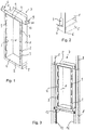
- Figur 1
- zeigt eine erfindungsgemäße Montageaufnahmeeinrichtung;
- Figur 2
- zeigt ein Detail aus
Fig. 1 unten rechts vergrößert; - Figur 3
- zeigt die Montageaufnahmeeinrichtung aus
Fig. 1 und 2 eingebaut in einem Montagegestell; - Figur 4
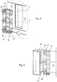
- zeigt die Montageaufnahmeeinrichtung aus
Fig. 3 nach Anbringung von Wandpaneelen vor dem Montagegestell und der Montageaufnahmeeinrichtung ausFig. 3 zusammen mit einem davor gezeichneten Kasten als Montagehilfseinrichtung; - Figur 5
- zeigt die Situation aus
Fig. 4 nach Einbau der Montagehilfseinrichtung in der Wand und in der Montageaufnahmeeinrichtung und nach Verkleiden der Paneele mit Fliesen und darüber hinaus davor eine Einbaubox zum Einbau in die Montagehilfseinrichtung; - Figur 6
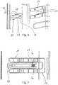
- zeigt einen mittleren Teil der
Fig. 5 vergrößert zur Verdeutlichung einer erfindungsgemäßen Formschlusseinrichtung; - Figur 7
- zeigt eine solche Formschlusseinrichtung wie in
Fig. 6 , allerdings nicht perspektivisch, sondern in Seitenansicht und im eingeführten Zustand; - Figur 8
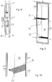
- zeigt eine Schnittdarstellung entsprechend der Linie C-C in
Fig. 7 ; - Figur 9
- zeigt die Situation aus
Fig. 5 nach Einbau der Einbaubox in der Wand in Verbindung mit Ablageböden; - Figur 10
- zeigt den oberen der Ablageböden aus
Fig. 9 in der Einbaubox in perspektivischer Ansicht von schräg unten. -
Fig. 1, 2 und 3 zeigen zunächst eine erfindungsgemäße Montagehilfseinrichtung, nämlich zunächst einen geschlossenen Blechrahmen 1 mit in Perspektive auf eine Wand (inFig. 1 bis 3 von unten schräg links) rechteckiger Grundform und Hochkantformat. Die Wände dieses Rahmens 1 sind dabei (ohne die nach vorne stehenden Laschen 3) etwa 10 mm tief. Der Rahmen 1 weist zudem nach vorn einen umgebogenen und umlaufenden Flansch 2 auf, wobei an dessen vertikalen Teilen jeweils sechs rechteckige Blechlaschen 3 aus dem Flansch 2 ausgespart sind und stattdessen in der Tiefenrichtung (vertikal zur Wandebene) nach vorn vorstehen. Analog stehen auch oben und unten Blechlaschen 4 in gleicher Tiefe nach vorn vor, verbinden aber dabei die jeweils obersten und untersten seitlichen Laschen 3. Auch diese Blechlaschen 4 sind aus dem umgebogenen Flansch 2 ausgespart. Damit bilden also die Blechwände des Rahmens 1 gemeinsam mit den Blechlaschen 3 und 4 Plattenelemente im Sinn der Ansprüche, die in den Ecken Winkelstücke bilden. Dabei gehen die Plattenelemente mit Ausnahme der vordersten Ebene der Laschen 3 und 4 ineinander über und bilden einen geschlossenen Rahmen; in der vordersten Ebene sind sie an den vertikalen Kanten zugunsten einer einfacheren Herstellung unterbrochen. Dadurch kann der umgebogene Flansch 2 aus dem gleichen Blechstück durch einfache Stanz- und Biegevorgänge hergestellt werden. Gleichzeitig betragen die Abstände zwischen den Laschen 3 jeweils weniger als ein Zehntel der Gesamtkantenlänge, die durch die jeweiligen Laschen 3 auf der rechten bzw. linken Seite miteinander definiert ist. - Im unteren Bereich, den
Fig. 2 deutlicher zeigt, schließt sich an den Blechrahmen 1 ein nach unten offenes U-Profil 5 (in der Perspektive von vorn) an, das die Tiefe des Blechrahmens 1 aufnimmt und in der Breite dem Flansch 2 entspricht. An den relativ kurzen Schenkeln dieses U-Profils 5 finden sich relativ weit vorn vertikal nach unten vorstehende Vorsprünge 6. -
Fig. 3 zeigt die Montagehilfseinrichtung, die hier summarisch mit 7 bezeichnet wird, im montierten Zustand zwischen zwei vertikalen Stützen 8 eines üblichen Montagegestells für Sanitärgegenstände. Es könnte sich hier aber auch um Trockenbauständer oder Ähnliches handeln. Zur Montage dienen zunächst zwei inFig. 1 oben sichtbare und seitlich über den Blechrahmen 1 hinausstehende Träger 9, die in vertikalen und zur Wand senkrecht stehenden Anlageflächen 10 enden. Mit diesen Anlageflächen 10 ist die Montageaufnahmeeinrichtung 7 inFig. 3 an die Stützen 8 angeschraubt, wobei die richtige Position in der Tiefenrichtung erreicht ist durch Anlage von zu den Anlageflächen 10 rechtwinkligen Blechstücken 11 von hinten an die Stützen 8. - Andererseits sitzt die Montagehilfseinrichtung 7 im unteren Bereich mit dem U-Profil 5 auf einem Rahmen 12 auf, der an sich vorbekannt ist. Solche Rahmen 12 können z. B. zur Montage einer Wassermischarmatur für eine Dusche oder Ähnliches benutzt werden und sind insoweit in vielen Fällen ohnehin vorhanden. Bspw. kann ein solcher Rahmen 12 bereits aus anderen Gründen vorgesehene Öffnungen auf seiner Oberseite aufweisen, an die die oben erwähnten Vorsprünge 6 angepasst sind und in die sie dementsprechend (bzgl. einer horizontalen Verschiebung) formschlüssig eingreifen können. Damit sind die Elemente 10 und 11 nur im oberen Bereich nötig, wobei diese natürlich auch unten und damit z. B. insgesamt vierfach vorgesehen sein können, wenn bspw. kein Rahmen 12 verfügbar ist. Statt des Rahmens 12 kann aber z. B. auch eine Quertraverse zwischen die Stützen 8 montiert werden und eine ähnliche Funktion übernehmen.
- Das hinten oben an dem Rahmen 1 über diesen hinaus nach oben ragende Blechstück erlaubt übrigens bei Bedarf die Montage einer den Rahmen 1 rückseitig schließenden Brandschutzplatte.
- Wie sich aus
Fig. 3 und auch der nachfolgenden Beschreibung deutlich ergibt, hält der Blechrahmen 1 mit seinen Seitenwänden und den Laschen 3 und 4 in der noch nicht fertiggestellten Trockenbauwand ein im Folgenden noch benötigtes Bauvolumen frei. Insbesondere verhindert er durch seine beträchtliche Tiefe (im Vergleich zu den Stützen 8) ein Verbauen des Bauvolumens mit anderen Einrichtungen, insbesondere das Verlegen von Wasser- oder Elektroleitungen durch das Bauvolumen hindurch, die dann später den Einbau des eigentlich zu installierenden Elements verhindern könnten. Damit wird dem Umstand Rechnung getragen, dass auf einer Baustelle häufig verschiedene Gewerke parallel und faktisch auch unkoordiniert arbeiten. Sollte z. B. eine Elektroleitung hinter dem Blechrahmen 1 quer verlegt werden, stört dies nicht, denn die Tiefe des Blechrahmens 1 (einschließlich der Laschen 3 und 4) genügt als Bauvolumen. - In dem in
Fig. 3 dargestellten Zustand kann die Trockenbau- oder Vorwand weitergebaut werden, in dem vor die Stützen 8 übliche Wandpaneele als Verkleidungsplatten montiert werden, die typischerweise in relativ großen Formaten und mit horizontalen und vertikalen Kanten verbaut werden. Dabei dienen die Laschen 3 und 4 zur Anlage von Wandpaneelen. Letztere werden dabei in horizontaler Richtung mit einer vertikalen Begrenzungskante an die Laschen 3 herangeschoben und durch Anlage daran justiert. Umgekehrt können Paneele mit horizontaler Begrenzungskante an die Laschen 4 herangeschoben werden, und zwar in vertikaler Richtung. Jedenfalls fällt es dem Trockenbauer oder sonstigen Monteur leicht, die inFig. 4 dargestellte Paneelwand 13 so zu erstellen, dass diese passgenau an die durch die Laschen 3 und Blechstücke 4 definierte vorderseitige Öffnung der Montagehilfsrichtung 7 anschließt. Dabei ist hier beispielhaft unter der Öffnung eine weitere kreisrunde Öffnung für eine Mischarmatur gezeichnet, die aber für die Erfindung keine wesentliche Rolle spielt. - Dabei sind die Laschen 3 und 4 übrigens in ihrer Tiefe so bemessen, dass sie höchstens die Stärke des dünnsten in Betracht kommenden Materials der Paneele ausmachen. Sie ragen also keinesfalls über diese Wandverkleidung nach vorne vor, sondern bleiben in vielen Fällen in der Tiefenrichtung hinter den Paneelen zurück, was ihre Funktion als Anlage nicht berührt.
- In diesem Zustand kann eine in
Fig. 4 ebenfalls und dort noch vor der Öffnung der Montagehilfseinrichtung 7 gezeichnetes Einrichtung eingebaut werden. Dabei handelt es sich um einen Kasten 14, der aus tiefgezogenem Kunststoff besteht und der mit drei horizontal verlaufenden und ihn seitlich und hinten umfassenden Klammern 15 versehen ist. Die Klammern enden jeweils vorderseitig in wandparallelen Endabschnitten 16 mit jeweils einem zentralen Montageloch. Dieser Kasten 14 bildet eine Montageaufnahmeeinrichtung im Sinn der vorstehenden Beschreibung und kann, wieFig. 4 verdeutlicht, in die Montagehilfseinrichtung 7 eingeschoben werden. Darin ist er mit leichtem Untermaß (also Spiel) untergebracht, wird aber letztlich durch Aufschrauben mittels der Montagelöcher in den Endabschnitten 16 der Klammern 15 auf die Paneelwand 13 montiert. Dabei kann eine hier nicht näher dargestellte Dichtung zum Abdichten des Spalts zwischen der Montageaufnahmeeinrichtung (dem Kasten) 14 und der Montagehilfseinrichtung 7 eingesetzt werden. - Hierbei erweist sich der Flansch 2 der Montagehilfseinrichtung 7 als günstig. Es können z. B. selbstschneidende Schrauben eingesetzt werden, die nach Durchtritt durch die entsprechende Paneelwand der Verkleidung 13 in den Flansch eindringen und sich dort ein Gegengewinde schneiden. Natürlich könnte der Flansch 2 auch entsprechende Löcher oder Gewinde aufweisen, wobei die Montage dann etwas justagesensibler wird. Außerdem könnte der Flansch 2 auch ersetzt sein durch einzelne Laschen, also in der Wandebene seitlich wegstehende Laschen ähnlich den nach vorne stehenden Laschen 3 und z. B. zwischen diesen Laschen 3.
- Die Paneelwand 13 kann daraufhin mit der obersten Wandverkleidung in einer an sich bekannten Weise versehen werden, also z. B. unter Zwischenschaltung von Dichtlagen und ähnlichem. Bspw. kann die Wandverkleidung aus großen Fliesenplatten 17 wie in
Fig. 5 oder auch aus Natursteinplatten oder ähnlichem bestehen. Dabei ist der Rand des Kastens 14 in der Tiefenrichtung so bemessen, dass er höchstens so weit vorragt wie die Endabschnitte 16 der Klammern 15 oder jedenfalls höchstens so weit wie die zusätzliche Stärke des dünnsten in Betracht kommenden Materials für die oberste Wandverkleidung. Er ragt also keinesfalls über diese oberste Wandverkleidung nach vorn vor, sondern bleibt in vielen Fällen in der Tiefenrichtung dahinter zurück. - In der Situation gemäß
Fig. 5 kann wiederum eine dort eingezeichnete Einbaubox 18 als zu montierendes Element eingeschoben werden, wobei die Einbaubox 18 einen nach außen etwas wegstehenden Flansch zur Abdeckung der Kanten der obersten Wandverkleidung 17 aufweist. Im fertig montierten Zustand ist also nur dies Einbaubox 18 sichtbar. Dabei spielen Montageeinrichtungen eine Rolle, die schon inFig. 4 und auch inFig. 5 dargestellt sind und anhand der folgenden Figuren noch näher erläutert werden. - Dabei handelt es sich um insgesamt sechs untereinander gleiche Paare von Aufnahmen, nämlich Aufnahmegabeln 19, und Vorsprüngen, nämlich Schienen 20, vgl. die
Fig. 6 und 7 . Übrigens sind nur zwei Paare Schienen 20 an der Einbaubox 18 vorgesehen, aber sechs Paare Aufnahmegabeln 19 in dem Kasten 14. Das liegt bei diesem Ausführungsbeispiel daran, dass letzterer eine Oben/unten-Symmetrie hat, also auch umgekehrt montiert werden kann, wohingegen die Einbaubox 18 nur eine Montage ungefähr mittig und unten benötigt. -
Fig. 6 zeigt konkret eine perspektivische Detailansicht der Aufnahmegabeln 19 und der Schienen 20 in der gleichen Perspektive wieFig. 5 undFig. 7 zeigt eine geschnittene Draufsicht mit einer Schnittebene, die senkrecht zur Wandebene und vertikal verläuft. - Man sieht, dass die Schiene 20 zwischen die Zinken der Aufnahmegabeln 19 passt und eingeschoben werden kann, was einem Einschieben der Einbaubox 18 in die Montagehilfseinrichtung, also den Kasten 14, entspricht.
Fig. 7 zeigt dabei etwas deutlicher alsFig. 6 , dass die aneinander entlang laufenden Anlageflächen 21, 22 der Aufnahmegabeln 19 und der Schiene 20 jeweils gezahnt sind, wobei der jeweils äußere (inFig. 7 linke) Bereich ungezahnt ist. Dies betrifft ganz ungefähr 20 % der jeweiligen Länge. Wenn dabei zu Anfang des Einschiebens der gezahnte Abschnitt der beiden Anlageflächen 22 (oben und unten) der Schiene 20 entlang einem noch ungezahnten Teil der Anlageflächen 21 der Aufnahmegabeln 19 läuft, erleichtert das das Einführen. Im Bereich der eigentlich angestrebten Montagepositionen, in noch etwas stärker eingefahrenem Zustand als inFig. 7 dargestellt, liegen wiederum im Wesentlichen die ungezahnten Abschnitte aneinander an. - Ferner erkennt man am eingangsseitigen Ende der Anlageflächen 21 in der Aufnahmegabel 19 Anschrägungen zur Erleichterung des Einführens der Schiene 20.
- Die Schiene 20 hat ihrerseits ebenfalls eine Gabelform mit zwei Zinken 23, welche durch einen Keil 24 in ihrer Breite (in montierter Lage vertikal) auseinandergespreizt werden können. Dieser Keil 24 hat die Form einer rechteckigen Mutter und ist in
Fig. 7 in Draufsicht und inFig. 8 im Schnitt entlang der Achse eines zugehörigen Schraubbolzens 25 zu sehen, also entsprechend der Schnittlinie C-C inFig. 7 . Der Schraubbolzen 25 weist einen Innensechskanteingriff auf an einem Betätigungskopf, der entsprechendFig. 8 auf der entgegengesetzten Seite der Wand der Einbaubox 18 angebracht ist, an der die Schiene 20 montiert ist. Dementsprechend kann durch Anziehen des Schraubbolzens 25 der Keil 24 inFig. 8 nach links bewegt werden und drückt dabei mit seinen inFig. 8 gut erkennbaren Keilflächen komplementäre Schragflächen an den Innenseiten der Zinken 23 der Schiene 20 auseinander. - Durch dieses Verspannen werden die beiden Zinken 23 auseinandergedrückt, sodass die Verzahnungen der Anlageflächen 21 und 22 ineinander einrücken und ein Formschluss in der Tiefenrichtung, also in der Richtung in
Fig. 7 horizontal nach links oder rechts, entsteht. Dementsprechend kann die Montageeinrichtung aus der Aufnahmegabel 19 und der Schiene 20 zusammen mit der Verspanneinrichtung in Form des Keils 24 mit dem Schraubbolzen 25 als Formschlusseinrichtung im Sinne der oben stehenden Beschreibung bezeichnet werden. - Man erkennt, dass die Formschlusseinrichtung ein einfaches Einschieben der Einbaubox 18 in die Montagehilfseinrichtung, also in den Kasten 14, erlaubt und dabei z. B. die Vorderseite der Einbaubox 18 mit einem Flansch in einer gewünschten Weise bündig oder anderweitig zu der Fliesenverkleidung 17 eingestellt werden kann. Die gewünschte Tiefe lässt sich einfach wählen und dann fixieren, indem die Betätigungsköpfe der Schraubbolzen von innerhalb der Einbaubox 18 angezogen werden, vgl.
Fig. 9 . Dies versperrt die entsprechenden Formschlusseinrichtungen. Dementsprechend einfach kann die Einbaubox 18 umgekehrt wieder entnommen werden, nämlich durch Lösen der Schraubbolzen und Herausziehen. - Andererseits hält der Schraubbolzen 25 über den Keil 24 die Schiene 20 an ihrem in den
Fig. 6 und 7 rechten Ende und ist die Schiene 20 an ihrem linken Ende über einen weiteren Schraubbolzen gehalten. Die Betätigungsköpfe der beiden Schraubbolzen dienen gemäßFig. 9 als Auflagen für hier gitterartige Einbauteile 26, nämlich Ablageböden. Die Ablageböden haben dabei gemäßFig. 10 nach unten gerichtete U-förmige Haltevorrichtungen, in die die Betätigungsköpfe der Schraubbolzen in Eingriff kommen können. Damit erfüllen die Schraubbolzen eine Mehrfachfunktion zur Halterung der Einlageböden 26 und zur Halterung der Schinen 20 sowie gleichzeitig, in Form des Schraubbolzens 25, zum Verspannen der Zinken 23 der Schiene 20. - Wie sich aus den Figuren ergibt, dient ferner die Montageaufnahmeeinrichtung 14 in diesem Fall auch als Leckageschutz, denn es handelt sich auch um einen wasserdichten Kunststoffkasten, der in nicht gezeichneter Weise nach vorn abgedichtet ist. Man beachte, dass dabei an der Einbaubox 18 ein Flansch vorliegt, aber nicht an dem Kasten 14.
- Letzterer wiederum kann in einfacher Weise in der Montagehilfseinrichtung 7 angebracht werden. Diese könnte auch zur Befestigung der Montageaufnahmevorrichtung 14, also des Kastens 14, dienen, was aber hier nicht der Fall ist. Auch könnte die Einbaubox 18 im Prinzip direkt in der Montagehilfseinrichtung 7 montiert werden, und zwar auch mit analogen Formschlusseinrichtungen. Im vorliegenden Ausführungsbeispiel aber dient die Montagehilfseinrichtung erstens zur Erleichterung der Paneelbeplankung der Trockenbauwand, wie oben erläutert, und zweitens zur Freihaltung des entsprechenden Flächenbereichs in der Wand, wie oben bereits erläutert.
- Ferner könnte natürlich die Montageaufnahmeeinrichtung 7 durchaus auch als wasserdichter Kasten ausgeführt werden oder könnte der Kasten 14, wenn er mit entsprechenden Laschen oder Rahmenteilen versehen wäre, als Montagehilfseinrichtung vor der Beplankung verbaut werden.
Claims (15)
- Montagesatz aus
einem in einer Gebäudewand zu montierenden Element (14, 18) und einer Montagehilfseinrichtung (7) für das Montieren des Elements (14, 18) in der Gebäudewand durch Montieren der Montagehilfseinrichtung (7) in der Gebäudewand und Montieren des Elements (14, 18) in der Montagehilfseinrichtung (7),
welche Montagehilfseinrichtung (7) Plattenelemente (1, 3, 4) aufweist, welche im montierten Zustand in einer wandparallelen Ebene eine Außenkontur eines Flächenbedarfs des zu montierenden Elements (14, 18) aus horizontalen und vertikalen Begrenzungslinien festlegen und welche im montierten Zustand in einer Tiefenrichtung senkrecht zu der wandparallelen Ebene mindestens die Tiefe des zu montierenden Elements (14, 18) in dieser Tiefenrichtung haben. - Montagesatz nach Anspruch 1, bei dem die Plattenelemente (1, 3, 4) in der Tiefenrichtung zumindest abschnittsweise so weit vorstehen, dass beim Anlegen horizontal und vertikal begrenzter Wandverkleidungsplatten (13) in der wandparallelen Ebene von außen an die Plattenelemente (1, 3, 4) der für die Montage des zu montierenden Elements (14, 18) nötige Flächenbedarf frei bleibt.
- Montagesatz nach Anspruch 1 oder 2, bei dem die Montagehilfseinrichtung (7) vier Winkelstücke (1, 3, 4), jeweils für eine Ecke eines Rechtecks in der wandparallelen Ebene, aufweist.
- Montagesatz nach einem der vorstehenden Ansprüche, bei dem die Montagehilfseinrichtung (7) so ausgelegt ist, dass die Lücken entlang der Außenkontur zwischen den diese definierenden Plattenelementen (3) der Montagehilfseinrichtung (7) jeweils höchstens 50 % der jeweiligen Länge der Außenkontur in der betreffenden Richtung ausmachen.
- Montagesatz nach einem der vorstehenden Ansprüche, bei dem die Montagehilfseinrichtung (7) einen umlaufenden Rahmen (1) aufweist, der im montierten Zustand in der wandparallelen Ebene nach vorn für die Montage des zu montierenden Elements (14, 18) offen ist und im montierten Zustand des Elements (14, 18) dieses in der wandparallelen Ebene umfasst.
- Montagesatz nach einem der vorstehenden Ansprüche, bei dem die Montagehilfseinrichtung (7) von den die Außenkontur definierenden Plattenelementen (1, 3, 4) horizontal nach außen beabstandete Anlageflächen (10, 11) zu ihrer Befestigung an vertikalen Stützen (8) in der Wand aufweist.
- Montagesatz nach einem der vorstehenden Ansprüche, bei dem die Montagehilfseinrichtung (7) zusätzlich zu den die Außenkontur definierenden Plattenelementen (3) in der wandparallelen Ebene und nach außen davon beabstandet eine wandparallele Anlagefläche (2) aufweist zur Befestigung des zu montierenden Elements (14, 18) mittels durch das Element (14, 18), durch eine bei der Montage anzubringende Wandverkleidungsplatte (13) und durch die wandparallele Anlagefläche (2) der Montagehilfseinrichtung (7) durchzuführende Bolzen.
- Montagesatz nach einem der vorstehenden Ansprüche, bei dem das zu montierende Element eine Wandeinbaubox (18) ist, die, abgesehen von einer Öffnung in der Vorderseite, im Übrigen geschlossen ist.
- Montagesatz nach einem der vorstehenden Ansprüche mit zusätzlich
einer Formschlusseinrichtung zu dem Montieren des Elements in der Montagehilfseinrichtung, welche Formschlusseinrichtung aufweist
eine Aufnahme an dem Element oder der Montagehilfseinrichtung,
einen Vorsprung an der Montagehilfseinrichtung bzw. dem Element, und zwar zum Eingriff in die Aufnahme,
eine Spanneinrichtung zum Verspannen der Aufnahme und des Vorsprungs gegeneinander,
wobei bei der Montage des Elements in der Montagehilfseinrichtung der Vorsprung in die Aufnahme eingeführt und darin in einer Tiefenrichtung verschoben werden kann bis zu einer Montageposition des Vorsprungs in der Aufnahme,
wobei der Vorsprung und die Aufnahme dann mit der Spanneinrichtung gegeneinander verspannt werden können und im verspannten Zustand nicht mehr verschiebbar sind,
wobei bei dem Verschieben der Vorsprung an einer Anlagefläche der Aufnahme oder die Aufnahme entlang einer Anlagefläche des Vorsprungs läuft und bei dem Verspannen dagegen verspannt wird,
und wobei die Anlagefläche höhenstrukturiert ist und die höhenstrukturierte Form bei dem Verschieben an verschiedenen Montagepositionen einen Formschluss mit dem Vorsprung bzw. der Aufnahme bezüglich der Tiefeneinrichtung durch die Verspannung ermöglicht. - Montagesatz nach Anspruch 5, optional in Verbindung mit einem weiteren der Ansprüche 6 bis 9, mit zusätzlich einem rückseitigen wandparallelen Anlagestück zur optionalen Montage einer Rückwand, bspw. Feuerschutzplatte, wobei das wandparallele Anlagestück vorzugsweise über den freigehaltenen Flächenbedarf hinausragt und vorzugsweise in Bezug auf diesen oben an dessen Rand vorgesehen ist.
- Montagesatz nach einem der vorstehenden Ansprüche mit zusätzlich einem in Bezug auf die freigehaltene Fläche nach außen vorstehenden Stift (6) zum Eingriff in ein Loch eines Montagegestells (12) bei der Montage, wobei der Stift (6) vorzugsweise vertikal, vorzugsweise nach unten und vorzugsweise in einer Mehrzahl vorgesehen ist.
- Verwendung einer Montagehilfseinrichtung (7) in einem Montagesatz nach einem der vorstehenden Ansprüche zur Montage des Elements (14, 18) in der Gebäudewand durch Montieren der Montagehilfseinrichtung (7) in der Gebäudewand und Montieren des Elements (14, 18) in der Montagehilfseinrichtung (7), wobei die Plattenelemente (1, 3, 4) der Montagehilfseinrichtung (7) im montierten Zustand in einer wandparallelen Ebene eine Außenkontur eines Flächenbedarfs des zu montierenden Elements (14, 18) aus horizontalen und vertikalen Begrenzungslinien festlegen und im montierten Zustand in der Tiefenrichtung den für das Element (14, 18) benötigten Bauraum umreißen.
- Verwendung nach Anspruch 12, bei der die Plattenelemente (3, 4) in der Tiefenrichtung zumindest abschnittsweise so weit vorstehen, dass beim Anlegen horizontal und vertikal begrenzter Wandverkleidungsplatten (13) in der wandparallelen Ebene von außen an die Plattenelemente (3, 4) der für die Montage des zu montierenden Elements (14, 18) nötige Flächenbedarf frei bleibt.
- Verwendung nach Anspruch 12 oder 13, bei welcher in der Wand vertikale Stützen (8) vorgesehen sind und die Montagehilfseinrichtung (7) zwischen und an den Stützen (8) montiert wird.
- Verwendung nach Anspruch 14, bei welcher die Montagehilfseinrichtung (7) auf einem zwischen den Stützen (8) vorgesehenen Untergestell (12) oder einer zwischen den Stützen vorgesehenen Quertraverse abgesetzt wird.
Priority Applications (1)
| Application Number | Priority Date | Filing Date | Title |
|---|---|---|---|
| EP18161484.3A EP3540135B1 (de) | 2018-03-13 | 2018-03-13 | Verwendung eines montagesatzes |
Applications Claiming Priority (1)
| Application Number | Priority Date | Filing Date | Title |
|---|---|---|---|
| EP18161484.3A EP3540135B1 (de) | 2018-03-13 | 2018-03-13 | Verwendung eines montagesatzes |
Publications (2)
| Publication Number | Publication Date |
|---|---|
| EP3540135A1 true EP3540135A1 (de) | 2019-09-18 |
| EP3540135B1 EP3540135B1 (de) | 2021-02-24 |
Family
ID=61628215
Family Applications (1)
| Application Number | Title | Priority Date | Filing Date |
|---|---|---|---|
| EP18161484.3A Active EP3540135B1 (de) | 2018-03-13 | 2018-03-13 | Verwendung eines montagesatzes |
Country Status (1)
| Country | Link |
|---|---|
| EP (1) | EP3540135B1 (de) |
Citations (4)
| Publication number | Priority date | Publication date | Assignee | Title |
|---|---|---|---|---|
| US3620404A (en) * | 1969-12-04 | 1971-11-16 | Accessory Specialties Inc | Fastener assembly for mounting of wall-recessed cabinets and similar fixtures |
| DE4124460A1 (de) * | 1991-07-24 | 1993-01-28 | Mero Werke Kg | Installationsblock |
| DE4309107A1 (de) * | 1993-03-22 | 1994-09-29 | Mepa Pauli Und Menden Gmbh | Vorwandmontage-Anordnung für Sanitärzwecke |
| EP2896756A1 (de) * | 2014-01-20 | 2015-07-22 | Easy Sanitary Solutions B.V. | Vorrichtung zum einbau in einer vorwand |
-
2018
- 2018-03-13 EP EP18161484.3A patent/EP3540135B1/de active Active
Patent Citations (4)
| Publication number | Priority date | Publication date | Assignee | Title |
|---|---|---|---|---|
| US3620404A (en) * | 1969-12-04 | 1971-11-16 | Accessory Specialties Inc | Fastener assembly for mounting of wall-recessed cabinets and similar fixtures |
| DE4124460A1 (de) * | 1991-07-24 | 1993-01-28 | Mero Werke Kg | Installationsblock |
| DE4309107A1 (de) * | 1993-03-22 | 1994-09-29 | Mepa Pauli Und Menden Gmbh | Vorwandmontage-Anordnung für Sanitärzwecke |
| EP2896756A1 (de) * | 2014-01-20 | 2015-07-22 | Easy Sanitary Solutions B.V. | Vorrichtung zum einbau in einer vorwand |
Also Published As
| Publication number | Publication date |
|---|---|
| EP3540135B1 (de) | 2021-02-24 |
Similar Documents
| Publication | Publication Date | Title |
|---|---|---|
| DE10136681C2 (de) | Rahmengestell | |
| DE102008012144B4 (de) | Haltebeschlag und Bodenbelag | |
| DE3004245C2 (de) | Deckenschalung mit Fallköpfen | |
| EP3540136B1 (de) | Wandmontagevorrichtung | |
| DE202007019167U1 (de) | Anordnung mit in einer Trockenbauwand angeordneten Schrankkorpussen zur Aufbewahrung von Gegenständen | |
| DE202018001321U1 (de) | Behältnis zum Wandeinbau | |
| DE2814713A1 (de) | Zerlegbare trennwand | |
| DE19618138A1 (de) | Raumhohe Absperrvorrichtung | |
| EP3540135B1 (de) | Verwendung eines montagesatzes | |
| EP3321430A1 (de) | Befestigung einer abdeckplatte einer revisionsöffnung | |
| DE4342362C1 (de) | Tragestruktur zum Ausrichten eines Möbels, insbesondere für höhenverstellbare Sockel für Einzelschränke und/oder Schränke einer Schrankwand | |
| DE202018001322U1 (de) | Montagesatz für in einer Gebäudewand zu montierendes Element | |
| DE202018001323U1 (de) | Wandmontagevorrichtung | |
| DE29509555U1 (de) | Schaltschrank mit Montageplatte als Einzel- oder Anreihschrank | |
| WO2011131641A1 (de) | Einbauschrankanordnung | |
| DE202009001539U1 (de) | Beschlagsystem zur wandhängenden Montage von Möbelkorpussen | |
| DE10033304C1 (de) | Verbindersystem für Bauelemente und Möbelkonstruktionen | |
| EP1384421B1 (de) | Sockelblende | |
| DE102016111211A1 (de) | Schalungssystem für die Errichtung niedriger Bauabschnitte aus Ortbeton | |
| DE10320003A1 (de) | Positioniervorrichtung, Schalungseinheit und Wandschalung | |
| AT403306B (de) | Anordnung zur zumindest vorübergehenden halterung des in gebrauchslage unteren randbereiches einer schalplatte, einer schaltafel, eines wandelementes oder dergleichen | |
| EP3540147B1 (de) | Behältnis zum wandeinbau | |
| DE202010000963U1 (de) | Duschablaufanordnung | |
| DE29713041U1 (de) | Duschwannenträger | |
| DE202017002529U1 (de) | Montageeinrichtung für einen Sanitärgegenstand |
Legal Events
| Date | Code | Title | Description |
|---|---|---|---|
| PUAI | Public reference made under article 153(3) epc to a published international application that has entered the european phase |
Free format text: ORIGINAL CODE: 0009012 |
|
| STAA | Information on the status of an ep patent application or granted ep patent |
Free format text: STATUS: REQUEST FOR EXAMINATION WAS MADE |
|
| 17P | Request for examination filed |
Effective date: 20181115 |
|
| AK | Designated contracting states |
Kind code of ref document: A1 Designated state(s): AL AT BE BG CH CY CZ DE DK EE ES FI FR GB GR HR HU IE IS IT LI LT LU LV MC MK MT NL NO PL PT RO RS SE SI SK SM TR |
|
| AX | Request for extension of the european patent |
Extension state: BA ME |
|
| STAA | Information on the status of an ep patent application or granted ep patent |
Free format text: STATUS: EXAMINATION IS IN PROGRESS |
|
| 17Q | First examination report despatched |
Effective date: 20200317 |
|
| RBV | Designated contracting states (corrected) |
Designated state(s): AL AT BE BG CH CY CZ DE DK EE ES FI FR GB GR HR HU IE IS IT LI LT LU LV MC MK MT NL NO PL PT RO RS SE SI SK SM TR |
|
| GRAP | Despatch of communication of intention to grant a patent |
Free format text: ORIGINAL CODE: EPIDOSNIGR1 |
|
| STAA | Information on the status of an ep patent application or granted ep patent |
Free format text: STATUS: GRANT OF PATENT IS INTENDED |
|
| RIC1 | Information provided on ipc code assigned before grant |
Ipc: E03D 11/14 20060101AFI20200910BHEP Ipc: E03D 1/00 20060101ALN20200910BHEP Ipc: E04F 19/08 20060101ALI20200910BHEP Ipc: E03D 1/01 20060101ALN20200910BHEP Ipc: E03D 1/012 20060101ALI20200910BHEP Ipc: E03C 1/01 20060101ALN20200910BHEP Ipc: A47B 96/00 20060101ALI20200910BHEP |
|
| GRAJ | Information related to disapproval of communication of intention to grant by the applicant or resumption of examination proceedings by the epo deleted |
Free format text: ORIGINAL CODE: EPIDOSDIGR1 |
|
| STAA | Information on the status of an ep patent application or granted ep patent |
Free format text: STATUS: EXAMINATION IS IN PROGRESS |
|
| GRAP | Despatch of communication of intention to grant a patent |
Free format text: ORIGINAL CODE: EPIDOSNIGR1 |
|
| STAA | Information on the status of an ep patent application or granted ep patent |
Free format text: STATUS: GRANT OF PATENT IS INTENDED |
|
| INTG | Intention to grant announced |
Effective date: 20201006 |
|
| INTC | Intention to grant announced (deleted) | ||
| RIC1 | Information provided on ipc code assigned before grant |
Ipc: E04F 19/08 20060101ALI20201022BHEP Ipc: E03D 1/00 20060101ALN20201022BHEP Ipc: E03D 1/01 20060101ALN20201022BHEP Ipc: A47B 96/00 20060101ALI20201022BHEP Ipc: E03D 11/14 20060101AFI20201022BHEP Ipc: E03C 1/01 20060101ALN20201022BHEP Ipc: E03D 1/012 20060101ALI20201022BHEP |
|
| INTG | Intention to grant announced |
Effective date: 20201103 |
|
| GRAS | Grant fee paid |
Free format text: ORIGINAL CODE: EPIDOSNIGR3 |
|
| GRAA | (expected) grant |
Free format text: ORIGINAL CODE: 0009210 |
|
| STAA | Information on the status of an ep patent application or granted ep patent |
Free format text: STATUS: THE PATENT HAS BEEN GRANTED |
|
| AK | Designated contracting states |
Kind code of ref document: B1 Designated state(s): AL AT BE BG CH CY CZ DE DK EE ES FI FR GB GR HR HU IE IS IT LI LT LU LV MC MK MT NL NO PL PT RO RS SE SI SK SM TR |
|
| REG | Reference to a national code |
Ref country code: CH Ref legal event code: EP |
|
| REG | Reference to a national code |
Ref country code: DE Ref legal event code: R096 Ref document number: 502018003952 Country of ref document: DE |
|
| REG | Reference to a national code |
Ref country code: AT Ref legal event code: REF Ref document number: 1364596 Country of ref document: AT Kind code of ref document: T Effective date: 20210315 |
|
| REG | Reference to a national code |
Ref country code: IE Ref legal event code: FG4D Free format text: LANGUAGE OF EP DOCUMENT: GERMAN |
|
| REG | Reference to a national code |
Ref country code: CH Ref legal event code: NV Representative=s name: TR-IP CONSULTING LLC, CH |
|
| REG | Reference to a national code |
Ref country code: LT Ref legal event code: MG9D |
|
| REG | Reference to a national code |
Ref country code: NL Ref legal event code: MP Effective date: 20210224 |
|
| PG25 | Lapsed in a contracting state [announced via postgrant information from national office to epo] |
Ref country code: GR Free format text: LAPSE BECAUSE OF FAILURE TO SUBMIT A TRANSLATION OF THE DESCRIPTION OR TO PAY THE FEE WITHIN THE PRESCRIBED TIME-LIMIT Effective date: 20210525 Ref country code: HR Free format text: LAPSE BECAUSE OF FAILURE TO SUBMIT A TRANSLATION OF THE DESCRIPTION OR TO PAY THE FEE WITHIN THE PRESCRIBED TIME-LIMIT Effective date: 20210224 Ref country code: FI Free format text: LAPSE BECAUSE OF FAILURE TO SUBMIT A TRANSLATION OF THE DESCRIPTION OR TO PAY THE FEE WITHIN THE PRESCRIBED TIME-LIMIT Effective date: 20210224 Ref country code: NO Free format text: LAPSE BECAUSE OF FAILURE TO SUBMIT A TRANSLATION OF THE DESCRIPTION OR TO PAY THE FEE WITHIN THE PRESCRIBED TIME-LIMIT Effective date: 20210524 Ref country code: PT Free format text: LAPSE BECAUSE OF FAILURE TO SUBMIT A TRANSLATION OF THE DESCRIPTION OR TO PAY THE FEE WITHIN THE PRESCRIBED TIME-LIMIT Effective date: 20210624 Ref country code: BG Free format text: LAPSE BECAUSE OF FAILURE TO SUBMIT A TRANSLATION OF THE DESCRIPTION OR TO PAY THE FEE WITHIN THE PRESCRIBED TIME-LIMIT Effective date: 20210524 Ref country code: LT Free format text: LAPSE BECAUSE OF FAILURE TO SUBMIT A TRANSLATION OF THE DESCRIPTION OR TO PAY THE FEE WITHIN THE PRESCRIBED TIME-LIMIT Effective date: 20210224 |
|
| PG25 | Lapsed in a contracting state [announced via postgrant information from national office to epo] |
Ref country code: SE Free format text: LAPSE BECAUSE OF FAILURE TO SUBMIT A TRANSLATION OF THE DESCRIPTION OR TO PAY THE FEE WITHIN THE PRESCRIBED TIME-LIMIT Effective date: 20210224 Ref country code: RS Free format text: LAPSE BECAUSE OF FAILURE TO SUBMIT A TRANSLATION OF THE DESCRIPTION OR TO PAY THE FEE WITHIN THE PRESCRIBED TIME-LIMIT Effective date: 20210224 Ref country code: NL Free format text: LAPSE BECAUSE OF FAILURE TO SUBMIT A TRANSLATION OF THE DESCRIPTION OR TO PAY THE FEE WITHIN THE PRESCRIBED TIME-LIMIT Effective date: 20210224 Ref country code: LV Free format text: LAPSE BECAUSE OF FAILURE TO SUBMIT A TRANSLATION OF THE DESCRIPTION OR TO PAY THE FEE WITHIN THE PRESCRIBED TIME-LIMIT Effective date: 20210224 Ref country code: PL Free format text: LAPSE BECAUSE OF FAILURE TO SUBMIT A TRANSLATION OF THE DESCRIPTION OR TO PAY THE FEE WITHIN THE PRESCRIBED TIME-LIMIT Effective date: 20210224 |
|
| PG25 | Lapsed in a contracting state [announced via postgrant information from national office to epo] |
Ref country code: IS Free format text: LAPSE BECAUSE OF FAILURE TO SUBMIT A TRANSLATION OF THE DESCRIPTION OR TO PAY THE FEE WITHIN THE PRESCRIBED TIME-LIMIT Effective date: 20210624 |
|
| PG25 | Lapsed in a contracting state [announced via postgrant information from national office to epo] |
Ref country code: SM Free format text: LAPSE BECAUSE OF FAILURE TO SUBMIT A TRANSLATION OF THE DESCRIPTION OR TO PAY THE FEE WITHIN THE PRESCRIBED TIME-LIMIT Effective date: 20210224 Ref country code: EE Free format text: LAPSE BECAUSE OF FAILURE TO SUBMIT A TRANSLATION OF THE DESCRIPTION OR TO PAY THE FEE WITHIN THE PRESCRIBED TIME-LIMIT Effective date: 20210224 Ref country code: CZ Free format text: LAPSE BECAUSE OF FAILURE TO SUBMIT A TRANSLATION OF THE DESCRIPTION OR TO PAY THE FEE WITHIN THE PRESCRIBED TIME-LIMIT Effective date: 20210224 |
|
| REG | Reference to a national code |
Ref country code: DE Ref legal event code: R097 Ref document number: 502018003952 Country of ref document: DE |
|
| PG25 | Lapsed in a contracting state [announced via postgrant information from national office to epo] |
Ref country code: MC Free format text: LAPSE BECAUSE OF FAILURE TO SUBMIT A TRANSLATION OF THE DESCRIPTION OR TO PAY THE FEE WITHIN THE PRESCRIBED TIME-LIMIT Effective date: 20210224 Ref country code: RO Free format text: LAPSE BECAUSE OF FAILURE TO SUBMIT A TRANSLATION OF THE DESCRIPTION OR TO PAY THE FEE WITHIN THE PRESCRIBED TIME-LIMIT Effective date: 20210224 Ref country code: SK Free format text: LAPSE BECAUSE OF FAILURE TO SUBMIT A TRANSLATION OF THE DESCRIPTION OR TO PAY THE FEE WITHIN THE PRESCRIBED TIME-LIMIT Effective date: 20210224 Ref country code: DK Free format text: LAPSE BECAUSE OF FAILURE TO SUBMIT A TRANSLATION OF THE DESCRIPTION OR TO PAY THE FEE WITHIN THE PRESCRIBED TIME-LIMIT Effective date: 20210224 |
|
| REG | Reference to a national code |
Ref country code: BE Ref legal event code: MM Effective date: 20210331 |
|
| PLBE | No opposition filed within time limit |
Free format text: ORIGINAL CODE: 0009261 |
|
| STAA | Information on the status of an ep patent application or granted ep patent |
Free format text: STATUS: NO OPPOSITION FILED WITHIN TIME LIMIT |
|
| PG25 | Lapsed in a contracting state [announced via postgrant information from national office to epo] |
Ref country code: ES Free format text: LAPSE BECAUSE OF FAILURE TO SUBMIT A TRANSLATION OF THE DESCRIPTION OR TO PAY THE FEE WITHIN THE PRESCRIBED TIME-LIMIT Effective date: 20210224 Ref country code: AL Free format text: LAPSE BECAUSE OF FAILURE TO SUBMIT A TRANSLATION OF THE DESCRIPTION OR TO PAY THE FEE WITHIN THE PRESCRIBED TIME-LIMIT Effective date: 20210224 Ref country code: LU Free format text: LAPSE BECAUSE OF NON-PAYMENT OF DUE FEES Effective date: 20210313 Ref country code: IE Free format text: LAPSE BECAUSE OF NON-PAYMENT OF DUE FEES Effective date: 20210313 |
|
| 26N | No opposition filed |
Effective date: 20211125 |
|
| PG25 | Lapsed in a contracting state [announced via postgrant information from national office to epo] |
Ref country code: SI Free format text: LAPSE BECAUSE OF FAILURE TO SUBMIT A TRANSLATION OF THE DESCRIPTION OR TO PAY THE FEE WITHIN THE PRESCRIBED TIME-LIMIT Effective date: 20210224 |
|
| PG25 | Lapsed in a contracting state [announced via postgrant information from national office to epo] |
Ref country code: IS Free format text: LAPSE BECAUSE OF FAILURE TO SUBMIT A TRANSLATION OF THE DESCRIPTION OR TO PAY THE FEE WITHIN THE PRESCRIBED TIME-LIMIT Effective date: 20210624 |
|
| PG25 | Lapsed in a contracting state [announced via postgrant information from national office to epo] |
Ref country code: BE Free format text: LAPSE BECAUSE OF NON-PAYMENT OF DUE FEES Effective date: 20210331 |
|
| P01 | Opt-out of the competence of the unified patent court (upc) registered |
Effective date: 20230507 |
|
| PG25 | Lapsed in a contracting state [announced via postgrant information from national office to epo] |
Ref country code: CY Free format text: LAPSE BECAUSE OF FAILURE TO SUBMIT A TRANSLATION OF THE DESCRIPTION OR TO PAY THE FEE WITHIN THE PRESCRIBED TIME-LIMIT Effective date: 20210224 |
|
| PG25 | Lapsed in a contracting state [announced via postgrant information from national office to epo] |
Ref country code: HU Free format text: LAPSE BECAUSE OF FAILURE TO SUBMIT A TRANSLATION OF THE DESCRIPTION OR TO PAY THE FEE WITHIN THE PRESCRIBED TIME-LIMIT; INVALID AB INITIO Effective date: 20180313 |
|
| PG25 | Lapsed in a contracting state [announced via postgrant information from national office to epo] |
Ref country code: MK Free format text: LAPSE BECAUSE OF FAILURE TO SUBMIT A TRANSLATION OF THE DESCRIPTION OR TO PAY THE FEE WITHIN THE PRESCRIBED TIME-LIMIT Effective date: 20210224 |
|
| PG25 | Lapsed in a contracting state [announced via postgrant information from national office to epo] |
Ref country code: TR Free format text: LAPSE BECAUSE OF FAILURE TO SUBMIT A TRANSLATION OF THE DESCRIPTION OR TO PAY THE FEE WITHIN THE PRESCRIBED TIME-LIMIT Effective date: 20210224 |
|
| PG25 | Lapsed in a contracting state [announced via postgrant information from national office to epo] |
Ref country code: MT Free format text: LAPSE BECAUSE OF FAILURE TO SUBMIT A TRANSLATION OF THE DESCRIPTION OR TO PAY THE FEE WITHIN THE PRESCRIBED TIME-LIMIT Effective date: 20210224 |
|
| REG | Reference to a national code |
Ref country code: AT Ref legal event code: PC Ref document number: 1364596 Country of ref document: AT Kind code of ref document: T Owner name: GEBERIT INTERNATIONAL AG, CH Effective date: 20241118 |
|
| REG | Reference to a national code |
Ref country code: DE Ref legal event code: R082 Ref document number: 502018003952 Country of ref document: DE Representative=s name: SZYNKA SMORODIN PATENTANWAELTE PARTNERSCHAFT M, DE |
|
| PGFP | Annual fee paid to national office [announced via postgrant information from national office to epo] |
Ref country code: IT Payment date: 20250327 Year of fee payment: 8 |
|
| PGFP | Annual fee paid to national office [announced via postgrant information from national office to epo] |
Ref country code: CH Payment date: 20250401 Year of fee payment: 8 |
|
| REG | Reference to a national code |
Ref country code: CH Ref legal event code: R17 Free format text: ST27 STATUS EVENT CODE: U-0-0-R10-R17 (AS PROVIDED BY THE NATIONAL OFFICE) Effective date: 20251024 |
|
| REG | Reference to a national code |
Ref country code: CH Ref legal event code: U11 Free format text: ST27 STATUS EVENT CODE: U-0-0-U10-U11 (AS PROVIDED BY THE NATIONAL OFFICE) Effective date: 20260401 |
|
| PGFP | Annual fee paid to national office [announced via postgrant information from national office to epo] |
Ref country code: GB Payment date: 20260324 Year of fee payment: 9 |
|
| PGFP | Annual fee paid to national office [announced via postgrant information from national office to epo] |
Ref country code: DE Payment date: 20260320 Year of fee payment: 9 |
|
| PGFP | Annual fee paid to national office [announced via postgrant information from national office to epo] |
Ref country code: AT Payment date: 20260319 Year of fee payment: 9 |
|
| PGFP | Annual fee paid to national office [announced via postgrant information from national office to epo] |
Ref country code: FR Payment date: 20260324 Year of fee payment: 9 |