EP3540077B1 - Verfahren zur erzeugung von doppelschichten zur verwendung mit nanoporensensoren - Google Patents
Verfahren zur erzeugung von doppelschichten zur verwendung mit nanoporensensoren Download PDFInfo
- Publication number
- EP3540077B1 EP3540077B1 EP19165626.3A EP19165626A EP3540077B1 EP 3540077 B1 EP3540077 B1 EP 3540077B1 EP 19165626 A EP19165626 A EP 19165626A EP 3540077 B1 EP3540077 B1 EP 3540077B1
- Authority
- EP
- European Patent Office
- Prior art keywords
- nanopore
- molecule
- nucleic acid
- probe
- electrode
- Prior art date
- Legal status (The legal status is an assumption and is not a legal conclusion. Google has not performed a legal analysis and makes no representation as to the accuracy of the status listed.)
- Active
Links
- 238000000034 method Methods 0.000 title claims description 145
- 239000000523 sample Substances 0.000 claims description 266
- 150000007523 nucleic acids Chemical class 0.000 claims description 131
- 150000002632 lipids Chemical class 0.000 claims description 117
- 102000039446 nucleic acids Human genes 0.000 claims description 113
- 108020004707 nucleic acids Proteins 0.000 claims description 113
- 239000011148 porous material Substances 0.000 claims description 91
- 108091006146 Channels Proteins 0.000 claims description 80
- 239000000232 Lipid Bilayer Substances 0.000 claims description 80
- 239000000463 material Substances 0.000 claims description 75
- 239000000243 solution Substances 0.000 claims description 71
- 102000017033 Porins Human genes 0.000 claims description 61
- 108010013381 Porins Proteins 0.000 claims description 61
- 102000004169 proteins and genes Human genes 0.000 claims description 61
- 108090000623 proteins and genes Proteins 0.000 claims description 61
- 239000007788 liquid Substances 0.000 claims description 48
- 239000012528 membrane Substances 0.000 claims description 37
- 230000027455 binding Effects 0.000 claims description 34
- 239000007853 buffer solution Substances 0.000 claims description 32
- DIOQZVSQGTUSAI-UHFFFAOYSA-N decane Chemical compound CCCCCCCCCC DIOQZVSQGTUSAI-UHFFFAOYSA-N 0.000 claims description 32
- 229920000642 polymer Polymers 0.000 claims description 28
- 238000003780 insertion Methods 0.000 claims description 24
- 230000037431 insertion Effects 0.000 claims description 24
- 101710092462 Alpha-hemolysin Proteins 0.000 claims description 21
- 238000012163 sequencing technique Methods 0.000 claims description 21
- WTJKGGKOPKCXLL-RRHRGVEJSA-N phosphatidylcholine Chemical compound CCCCCCCCCCCCCCCC(=O)OC[C@H](COP([O-])(=O)OCC[N+](C)(C)C)OC(=O)CCCCCCCC=CCCCCCCCC WTJKGGKOPKCXLL-RRHRGVEJSA-N 0.000 claims description 15
- 108091028043 Nucleic acid sequence Proteins 0.000 claims description 14
- 238000000527 sonication Methods 0.000 claims description 12
- KILNVBDSWZSGLL-KXQOOQHDSA-N 1,2-dihexadecanoyl-sn-glycero-3-phosphocholine Chemical compound CCCCCCCCCCCCCCCC(=O)OC[C@H](COP([O-])(=O)OCC[N+](C)(C)C)OC(=O)CCCCCCCCCCCCCCC KILNVBDSWZSGLL-KXQOOQHDSA-N 0.000 claims description 10
- 239000012460 protein solution Substances 0.000 claims description 10
- 230000003993 interaction Effects 0.000 claims description 9
- 241000187480 Mycobacterium smegmatis Species 0.000 claims description 8
- 239000003960 organic solvent Substances 0.000 claims description 8
- PORPENFLTBBHSG-MGBGTMOVSA-N 1,2-dihexadecanoyl-sn-glycerol-3-phosphate Chemical compound CCCCCCCCCCCCCCCC(=O)OC[C@H](COP(O)(O)=O)OC(=O)CCCCCCCCCCCCCCC PORPENFLTBBHSG-MGBGTMOVSA-N 0.000 claims description 6
- TZCPCKNHXULUIY-RGULYWFUSA-N 1,2-distearoyl-sn-glycero-3-phosphoserine Chemical compound CCCCCCCCCCCCCCCCCC(=O)OC[C@H](COP(O)(=O)OC[C@H](N)C(O)=O)OC(=O)CCCCCCCCCCCCCCCCC TZCPCKNHXULUIY-RGULYWFUSA-N 0.000 claims description 6
- JZNWSCPGTDBMEW-UHFFFAOYSA-N Glycerophosphorylethanolamin Natural products NCCOP(O)(=O)OCC(O)CO JZNWSCPGTDBMEW-UHFFFAOYSA-N 0.000 claims description 6
- ZWZWYGMENQVNFU-UHFFFAOYSA-N Glycerophosphorylserin Natural products OC(=O)C(N)COP(O)(=O)OCC(O)CO ZWZWYGMENQVNFU-UHFFFAOYSA-N 0.000 claims description 6
- 150000008104 phosphatidylethanolamines Chemical class 0.000 claims description 6
- 150000003905 phosphatidylinositols Chemical class 0.000 claims description 6
- 239000004094 surface-active agent Substances 0.000 claims description 6
- ATBOMIWRCZXYSZ-XZBBILGWSA-N [1-[2,3-dihydroxypropoxy(hydroxy)phosphoryl]oxy-3-hexadecanoyloxypropan-2-yl] (9e,12e)-octadeca-9,12-dienoate Chemical compound CCCCCCCCCCCCCCCC(=O)OCC(COP(O)(=O)OCC(O)CO)OC(=O)CCCCCCC\C=C\C\C=C\CCCCC ATBOMIWRCZXYSZ-XZBBILGWSA-N 0.000 claims description 5
- AWUCVROLDVIAJX-UHFFFAOYSA-N alpha-glycerophosphate Natural products OCC(O)COP(O)(O)=O AWUCVROLDVIAJX-UHFFFAOYSA-N 0.000 claims description 5
- 108091023037 Aptamer Proteins 0.000 claims description 4
- 238000000151 deposition Methods 0.000 claims description 4
- 230000005661 hydrophobic surface Effects 0.000 claims description 4
- VEXZGXHMUGYJMC-UHFFFAOYSA-M Chloride anion Chemical compound [Cl-] VEXZGXHMUGYJMC-UHFFFAOYSA-M 0.000 claims description 3
- VMHLLURERBWHNL-UHFFFAOYSA-M Sodium acetate Chemical compound [Na+].CC([O-])=O VMHLLURERBWHNL-UHFFFAOYSA-M 0.000 claims description 3
- 239000000693 micelle Substances 0.000 claims description 3
- 235000017281 sodium acetate Nutrition 0.000 claims description 3
- 239000001632 sodium acetate Substances 0.000 claims description 3
- 239000002253 acid Substances 0.000 claims 1
- 102000040430 polynucleotide Human genes 0.000 description 120
- 108091033319 polynucleotide Proteins 0.000 description 120
- 239000002157 polynucleotide Substances 0.000 description 120
- 238000012360 testing method Methods 0.000 description 69
- 108020004414 DNA Proteins 0.000 description 52
- 102000053602 DNA Human genes 0.000 description 52
- WCUXLLCKKVVCTQ-UHFFFAOYSA-M Potassium chloride Chemical compound [Cl-].[K+] WCUXLLCKKVVCTQ-UHFFFAOYSA-M 0.000 description 52
- 125000003729 nucleotide group Chemical group 0.000 description 51
- 239000010410 layer Substances 0.000 description 46
- 239000002773 nucleotide Substances 0.000 description 45
- 239000004065 semiconductor Substances 0.000 description 36
- 239000000203 mixture Substances 0.000 description 30
- 230000015572 biosynthetic process Effects 0.000 description 29
- 239000001103 potassium chloride Substances 0.000 description 26
- 235000011164 potassium chloride Nutrition 0.000 description 26
- 108091034117 Oligonucleotide Proteins 0.000 description 21
- 229920002477 rna polymer Polymers 0.000 description 20
- 101100284769 Drosophila melanogaster hemo gene Proteins 0.000 description 17
- 239000003228 hemolysin Substances 0.000 description 17
- 230000008569 process Effects 0.000 description 17
- 238000003860 storage Methods 0.000 description 17
- 108010006464 Hemolysin Proteins Proteins 0.000 description 16
- 230000015654 memory Effects 0.000 description 16
- 238000001514 detection method Methods 0.000 description 15
- 230000000638 stimulation Effects 0.000 description 13
- PEDCQBHIVMGVHV-UHFFFAOYSA-N Glycerine Chemical compound OCC(O)CO PEDCQBHIVMGVHV-UHFFFAOYSA-N 0.000 description 12
- 239000003153 chemical reaction reagent Substances 0.000 description 12
- 239000000872 buffer Substances 0.000 description 11
- 239000003446 ligand Substances 0.000 description 9
- 238000012545 processing Methods 0.000 description 9
- YBJHBAHKTGYVGT-ZKWXMUAHSA-N (+)-Biotin Chemical compound N1C(=O)N[C@@H]2[C@H](CCCCC(=O)O)SC[C@@H]21 YBJHBAHKTGYVGT-ZKWXMUAHSA-N 0.000 description 8
- 208000035657 Abasia Diseases 0.000 description 8
- 229910021607 Silver chloride Inorganic materials 0.000 description 8
- 230000002209 hydrophobic effect Effects 0.000 description 8
- 108090000765 processed proteins & peptides Proteins 0.000 description 8
- XLYOFNOQVPJJNP-UHFFFAOYSA-N water Substances O XLYOFNOQVPJJNP-UHFFFAOYSA-N 0.000 description 8
- 108010090804 Streptavidin Proteins 0.000 description 7
- XAGFODPZIPBFFR-UHFFFAOYSA-N aluminium Chemical compound [Al] XAGFODPZIPBFFR-UHFFFAOYSA-N 0.000 description 7
- 230000000692 anti-sense effect Effects 0.000 description 7
- 238000004891 communication Methods 0.000 description 7
- 238000002474 experimental method Methods 0.000 description 7
- 239000012634 fragment Substances 0.000 description 7
- 102000004196 processed proteins & peptides Human genes 0.000 description 7
- HKZLPVFGJNLROG-UHFFFAOYSA-M silver monochloride Chemical compound [Cl-].[Ag+] HKZLPVFGJNLROG-UHFFFAOYSA-M 0.000 description 7
- 102000004190 Enzymes Human genes 0.000 description 6
- 108090000790 Enzymes Proteins 0.000 description 6
- BQCADISMDOOEFD-UHFFFAOYSA-N Silver Chemical compound [Ag] BQCADISMDOOEFD-UHFFFAOYSA-N 0.000 description 6
- 239000011324 bead Substances 0.000 description 6
- 238000002844 melting Methods 0.000 description 6
- 230000008018 melting Effects 0.000 description 6
- 150000003839 salts Chemical class 0.000 description 6
- 229910052709 silver Inorganic materials 0.000 description 6
- 239000004332 silver Substances 0.000 description 6
- 239000000126 substance Substances 0.000 description 6
- 239000000758 substrate Substances 0.000 description 6
- 150000001413 amino acids Chemical class 0.000 description 5
- 238000004458 analytical method Methods 0.000 description 5
- 238000012512 characterization method Methods 0.000 description 5
- 230000000295 complement effect Effects 0.000 description 5
- 238000012986 modification Methods 0.000 description 5
- 230000004048 modification Effects 0.000 description 5
- 230000003287 optical effect Effects 0.000 description 5
- 230000002269 spontaneous effect Effects 0.000 description 5
- CIWBSHSKHKDKBQ-JLAZNSOCSA-N Ascorbic acid Chemical compound OC[C@H](O)[C@H]1OC(=O)C(O)=C1O CIWBSHSKHKDKBQ-JLAZNSOCSA-N 0.000 description 4
- 101710088194 Dehydrogenase Proteins 0.000 description 4
- 102000003992 Peroxidases Human genes 0.000 description 4
- 229910052581 Si3N4 Inorganic materials 0.000 description 4
- XUIMIQQOPSSXEZ-UHFFFAOYSA-N Silicon Chemical compound [Si] XUIMIQQOPSSXEZ-UHFFFAOYSA-N 0.000 description 4
- FAPWRFPIFSIZLT-UHFFFAOYSA-M Sodium chloride Chemical compound [Na+].[Cl-] FAPWRFPIFSIZLT-UHFFFAOYSA-M 0.000 description 4
- ISAKRJDGNUQOIC-UHFFFAOYSA-N Uracil Chemical compound O=C1C=CNC(=O)N1 ISAKRJDGNUQOIC-UHFFFAOYSA-N 0.000 description 4
- JLCPHMBAVCMARE-UHFFFAOYSA-N [3-[[3-[[3-[[3-[[3-[[3-[[3-[[3-[[3-[[3-[[3-[[5-(2-amino-6-oxo-1H-purin-9-yl)-3-[[3-[[3-[[3-[[3-[[3-[[5-(2-amino-6-oxo-1H-purin-9-yl)-3-[[5-(2-amino-6-oxo-1H-purin-9-yl)-3-hydroxyoxolan-2-yl]methoxy-hydroxyphosphoryl]oxyoxolan-2-yl]methoxy-hydroxyphosphoryl]oxy-5-(5-methyl-2,4-dioxopyrimidin-1-yl)oxolan-2-yl]methoxy-hydroxyphosphoryl]oxy-5-(6-aminopurin-9-yl)oxolan-2-yl]methoxy-hydroxyphosphoryl]oxy-5-(6-aminopurin-9-yl)oxolan-2-yl]methoxy-hydroxyphosphoryl]oxy-5-(6-aminopurin-9-yl)oxolan-2-yl]methoxy-hydroxyphosphoryl]oxy-5-(6-aminopurin-9-yl)oxolan-2-yl]methoxy-hydroxyphosphoryl]oxyoxolan-2-yl]methoxy-hydroxyphosphoryl]oxy-5-(5-methyl-2,4-dioxopyrimidin-1-yl)oxolan-2-yl]methoxy-hydroxyphosphoryl]oxy-5-(4-amino-2-oxopyrimidin-1-yl)oxolan-2-yl]methoxy-hydroxyphosphoryl]oxy-5-(5-methyl-2,4-dioxopyrimidin-1-yl)oxolan-2-yl]methoxy-hydroxyphosphoryl]oxy-5-(5-methyl-2,4-dioxopyrimidin-1-yl)oxolan-2-yl]methoxy-hydroxyphosphoryl]oxy-5-(6-aminopurin-9-yl)oxolan-2-yl]methoxy-hydroxyphosphoryl]oxy-5-(6-aminopurin-9-yl)oxolan-2-yl]methoxy-hydroxyphosphoryl]oxy-5-(4-amino-2-oxopyrimidin-1-yl)oxolan-2-yl]methoxy-hydroxyphosphoryl]oxy-5-(4-amino-2-oxopyrimidin-1-yl)oxolan-2-yl]methoxy-hydroxyphosphoryl]oxy-5-(4-amino-2-oxopyrimidin-1-yl)oxolan-2-yl]methoxy-hydroxyphosphoryl]oxy-5-(6-aminopurin-9-yl)oxolan-2-yl]methoxy-hydroxyphosphoryl]oxy-5-(4-amino-2-oxopyrimidin-1-yl)oxolan-2-yl]methyl [5-(6-aminopurin-9-yl)-2-(hydroxymethyl)oxolan-3-yl] hydrogen phosphate Polymers Cc1cn(C2CC(OP(O)(=O)OCC3OC(CC3OP(O)(=O)OCC3OC(CC3O)n3cnc4c3nc(N)[nH]c4=O)n3cnc4c3nc(N)[nH]c4=O)C(COP(O)(=O)OC3CC(OC3COP(O)(=O)OC3CC(OC3COP(O)(=O)OC3CC(OC3COP(O)(=O)OC3CC(OC3COP(O)(=O)OC3CC(OC3COP(O)(=O)OC3CC(OC3COP(O)(=O)OC3CC(OC3COP(O)(=O)OC3CC(OC3COP(O)(=O)OC3CC(OC3COP(O)(=O)OC3CC(OC3COP(O)(=O)OC3CC(OC3COP(O)(=O)OC3CC(OC3COP(O)(=O)OC3CC(OC3COP(O)(=O)OC3CC(OC3COP(O)(=O)OC3CC(OC3COP(O)(=O)OC3CC(OC3COP(O)(=O)OC3CC(OC3CO)n3cnc4c(N)ncnc34)n3ccc(N)nc3=O)n3cnc4c(N)ncnc34)n3ccc(N)nc3=O)n3ccc(N)nc3=O)n3ccc(N)nc3=O)n3cnc4c(N)ncnc34)n3cnc4c(N)ncnc34)n3cc(C)c(=O)[nH]c3=O)n3cc(C)c(=O)[nH]c3=O)n3ccc(N)nc3=O)n3cc(C)c(=O)[nH]c3=O)n3cnc4c3nc(N)[nH]c4=O)n3cnc4c(N)ncnc34)n3cnc4c(N)ncnc34)n3cnc4c(N)ncnc34)n3cnc4c(N)ncnc34)O2)c(=O)[nH]c1=O JLCPHMBAVCMARE-UHFFFAOYSA-N 0.000 description 4
- 230000003213 activating effect Effects 0.000 description 4
- 238000003491 array Methods 0.000 description 4
- 229960002685 biotin Drugs 0.000 description 4
- 235000020958 biotin Nutrition 0.000 description 4
- 239000011616 biotin Substances 0.000 description 4
- 230000008859 change Effects 0.000 description 4
- 238000006243 chemical reaction Methods 0.000 description 4
- 150000001875 compounds Chemical class 0.000 description 4
- OPTASPLRGRRNAP-UHFFFAOYSA-N cytosine Chemical compound NC=1C=CNC(=O)N=1 OPTASPLRGRRNAP-UHFFFAOYSA-N 0.000 description 4
- UYTPUPDQBNUYGX-UHFFFAOYSA-N guanine Chemical compound O=C1NC(N)=NC2=C1N=CN2 UYTPUPDQBNUYGX-UHFFFAOYSA-N 0.000 description 4
- 239000001257 hydrogen Substances 0.000 description 4
- 229910052739 hydrogen Inorganic materials 0.000 description 4
- 125000004435 hydrogen atom Chemical class [H]* 0.000 description 4
- 238000002347 injection Methods 0.000 description 4
- 239000007924 injection Substances 0.000 description 4
- 150000002500 ions Chemical class 0.000 description 4
- 238000002955 isolation Methods 0.000 description 4
- 239000006193 liquid solution Substances 0.000 description 4
- 108040007629 peroxidase activity proteins Proteins 0.000 description 4
- 239000000843 powder Substances 0.000 description 4
- 229910052710 silicon Inorganic materials 0.000 description 4
- 239000010703 silicon Substances 0.000 description 4
- RWQNBRDOKXIBIV-UHFFFAOYSA-N thymine Chemical compound CC1=CNC(=O)NC1=O RWQNBRDOKXIBIV-UHFFFAOYSA-N 0.000 description 4
- DEQPBRIACBATHE-FXQIFTODSA-N 5-[(3as,4s,6ar)-2-oxo-1,3,3a,4,6,6a-hexahydrothieno[3,4-d]imidazol-4-yl]-2-iminopentanoic acid Chemical compound N1C(=O)N[C@@H]2[C@H](CCCC(=N)C(=O)O)SC[C@@H]21 DEQPBRIACBATHE-FXQIFTODSA-N 0.000 description 3
- UHOVQNZJYSORNB-UHFFFAOYSA-N Benzene Chemical compound C1=CC=CC=C1 UHOVQNZJYSORNB-UHFFFAOYSA-N 0.000 description 3
- 108091008103 RNA aptamers Proteins 0.000 description 3
- VYPSYNLAJGMNEJ-UHFFFAOYSA-N Silicium dioxide Chemical compound O=[Si]=O VYPSYNLAJGMNEJ-UHFFFAOYSA-N 0.000 description 3
- 238000007792 addition Methods 0.000 description 3
- 229910052782 aluminium Inorganic materials 0.000 description 3
- 230000001745 anti-biotin effect Effects 0.000 description 3
- 230000005540 biological transmission Effects 0.000 description 3
- 150000001720 carbohydrates Chemical class 0.000 description 3
- 235000014633 carbohydrates Nutrition 0.000 description 3
- 238000004520 electroporation Methods 0.000 description 3
- 238000009499 grossing Methods 0.000 description 3
- 238000005259 measurement Methods 0.000 description 3
- 230000009149 molecular binding Effects 0.000 description 3
- BASFCYQUMIYNBI-UHFFFAOYSA-N platinum Substances [Pt] BASFCYQUMIYNBI-UHFFFAOYSA-N 0.000 description 3
- 238000006116 polymerization reaction Methods 0.000 description 3
- 238000002360 preparation method Methods 0.000 description 3
- 230000004044 response Effects 0.000 description 3
- HQVNEWCFYHHQES-UHFFFAOYSA-N silicon nitride Chemical compound N12[Si]34N5[Si]62N3[Si]51N64 HQVNEWCFYHHQES-UHFFFAOYSA-N 0.000 description 3
- 239000007787 solid Substances 0.000 description 3
- 239000006228 supernatant Substances 0.000 description 3
- 238000011282 treatment Methods 0.000 description 3
- KHWCHTKSEGGWEX-RRKCRQDMSA-N 2'-deoxyadenosine 5'-monophosphate Chemical group C1=NC=2C(N)=NC=NC=2N1[C@H]1C[C@H](O)[C@@H](COP(O)(O)=O)O1 KHWCHTKSEGGWEX-RRKCRQDMSA-N 0.000 description 2
- NCMVOABPESMRCP-SHYZEUOFSA-N 2'-deoxycytosine 5'-monophosphate Chemical compound O=C1N=C(N)C=CN1[C@@H]1O[C@H](COP(O)(O)=O)[C@@H](O)C1 NCMVOABPESMRCP-SHYZEUOFSA-N 0.000 description 2
- LTFMZDNNPPEQNG-KVQBGUIXSA-N 2'-deoxyguanosine 5'-monophosphate Chemical compound C1=2NC(N)=NC(=O)C=2N=CN1[C@H]1C[C@H](O)[C@@H](COP(O)(O)=O)O1 LTFMZDNNPPEQNG-KVQBGUIXSA-N 0.000 description 2
- FZWGECJQACGGTI-UHFFFAOYSA-N 2-amino-7-methyl-1,7-dihydro-6H-purin-6-one Chemical compound NC1=NC(O)=C2N(C)C=NC2=N1 FZWGECJQACGGTI-UHFFFAOYSA-N 0.000 description 2
- ASJSAQIRZKANQN-CRCLSJGQSA-N 2-deoxy-D-ribose Chemical group OC[C@@H](O)[C@@H](O)CC=O ASJSAQIRZKANQN-CRCLSJGQSA-N 0.000 description 2
- OIVLITBTBDPEFK-UHFFFAOYSA-N 5,6-dihydrouracil Chemical compound O=C1CCNC(=O)N1 OIVLITBTBDPEFK-UHFFFAOYSA-N 0.000 description 2
- KDCGOANMDULRCW-UHFFFAOYSA-N 7H-purine Chemical compound N1=CNC2=NC=NC2=C1 KDCGOANMDULRCW-UHFFFAOYSA-N 0.000 description 2
- LRFVTYWOQMYALW-UHFFFAOYSA-N 9H-xanthine Chemical compound O=C1NC(=O)NC2=C1NC=N2 LRFVTYWOQMYALW-UHFFFAOYSA-N 0.000 description 2
- XFXPMWWXUTWYJX-UHFFFAOYSA-N Cyanide Chemical compound N#[C-] XFXPMWWXUTWYJX-UHFFFAOYSA-N 0.000 description 2
- 238000000018 DNA microarray Methods 0.000 description 2
- 108010067770 Endopeptidase K Proteins 0.000 description 2
- CWYNVVGOOAEACU-UHFFFAOYSA-N Fe2+ Chemical compound [Fe+2] CWYNVVGOOAEACU-UHFFFAOYSA-N 0.000 description 2
- -1 Na+ Chemical class 0.000 description 2
- 239000004820 Pressure-sensitive adhesive Substances 0.000 description 2
- 108091027967 Small hairpin RNA Proteins 0.000 description 2
- 108020004459 Small interfering RNA Proteins 0.000 description 2
- DJJCXFVJDGTHFX-UHFFFAOYSA-N Uridinemonophosphate Natural products OC1C(O)C(COP(O)(O)=O)OC1N1C(=O)NC(=O)C=C1 DJJCXFVJDGTHFX-UHFFFAOYSA-N 0.000 description 2
- OIRDTQYFTABQOQ-KQYNXXCUSA-N adenosine group Chemical group [C@@H]1([C@H](O)[C@H](O)[C@@H](CO)O1)N1C=NC=2C(N)=NC=NC12 OIRDTQYFTABQOQ-KQYNXXCUSA-N 0.000 description 2
- 239000012491 analyte Substances 0.000 description 2
- 239000000427 antigen Substances 0.000 description 2
- 108091007433 antigens Proteins 0.000 description 2
- 102000036639 antigens Human genes 0.000 description 2
- 239000007864 aqueous solution Substances 0.000 description 2
- 229960005070 ascorbic acid Drugs 0.000 description 2
- 235000010323 ascorbic acid Nutrition 0.000 description 2
- 239000011668 ascorbic acid Substances 0.000 description 2
- 239000003990 capacitor Substances 0.000 description 2
- 239000000470 constituent Substances 0.000 description 2
- 230000001276 controlling effect Effects 0.000 description 2
- IERHLVCPSMICTF-XVFCMESISA-N cytidine 5'-monophosphate Chemical compound O=C1N=C(N)C=CN1[C@H]1[C@H](O)[C@H](O)[C@@H](COP(O)(O)=O)O1 IERHLVCPSMICTF-XVFCMESISA-N 0.000 description 2
- IERHLVCPSMICTF-UHFFFAOYSA-N cytidine monophosphate Natural products O=C1N=C(N)C=CN1C1C(O)C(O)C(COP(O)(O)=O)O1 IERHLVCPSMICTF-UHFFFAOYSA-N 0.000 description 2
- 229940104302 cytosine Drugs 0.000 description 2
- GYOZYWVXFNDGLU-XLPZGREQSA-N dTMP Chemical compound O=C1NC(=O)C(C)=CN1[C@@H]1O[C@H](COP(O)(O)=O)[C@@H](O)C1 GYOZYWVXFNDGLU-XLPZGREQSA-N 0.000 description 2
- 238000013500 data storage Methods 0.000 description 2
- 230000001419 dependent effect Effects 0.000 description 2
- 238000003487 electrochemical reaction Methods 0.000 description 2
- 230000005669 field effect Effects 0.000 description 2
- 238000011049 filling Methods 0.000 description 2
- RQFCJASXJCIDSX-UUOKFMHZSA-N guanosine 5'-monophosphate Chemical compound C1=2NC(N)=NC(=O)C=2N=CN1[C@@H]1O[C@H](COP(O)(O)=O)[C@@H](O)[C@H]1O RQFCJASXJCIDSX-UUOKFMHZSA-N 0.000 description 2
- 235000013928 guanylic acid Nutrition 0.000 description 2
- FDGQSTZJBFJUBT-UHFFFAOYSA-N hypoxanthine Chemical compound O=C1NC=NC2=C1NC=N2 FDGQSTZJBFJUBT-UHFFFAOYSA-N 0.000 description 2
- 230000003100 immobilizing effect Effects 0.000 description 2
- 238000010348 incorporation Methods 0.000 description 2
- 229910044991 metal oxide Inorganic materials 0.000 description 2
- 150000004706 metal oxides Chemical class 0.000 description 2
- 125000004573 morpholin-4-yl group Chemical group N1(CCOCC1)* 0.000 description 2
- 230000002093 peripheral effect Effects 0.000 description 2
- 125000002467 phosphate group Chemical group [H]OP(=O)(O[H])O[*] 0.000 description 2
- 239000004033 plastic Substances 0.000 description 2
- 229920003023 plastic Polymers 0.000 description 2
- 229910052697 platinum Inorganic materials 0.000 description 2
- 229920001184 polypeptide Polymers 0.000 description 2
- 238000007781 pre-processing Methods 0.000 description 2
- 238000000746 purification Methods 0.000 description 2
- 238000004445 quantitative analysis Methods 0.000 description 2
- 230000002441 reversible effect Effects 0.000 description 2
- 239000012266 salt solution Substances 0.000 description 2
- 239000004055 small Interfering RNA Substances 0.000 description 2
- 239000011780 sodium chloride Substances 0.000 description 2
- 241000894007 species Species 0.000 description 2
- 229940113082 thymine Drugs 0.000 description 2
- 108020005087 unfolded proteins Proteins 0.000 description 2
- 229940035893 uracil Drugs 0.000 description 2
- DJJCXFVJDGTHFX-XVFCMESISA-N uridine 5'-monophosphate Chemical compound O[C@@H]1[C@H](O)[C@@H](COP(O)(O)=O)O[C@H]1N1C(=O)NC(=O)C=C1 DJJCXFVJDGTHFX-XVFCMESISA-N 0.000 description 2
- XKKCQTLDIPIRQD-JGVFFNPUSA-N 1-[(2r,5s)-5-(hydroxymethyl)oxolan-2-yl]-5-methylpyrimidine-2,4-dione Chemical compound O=C1NC(=O)C(C)=CN1[C@@H]1O[C@H](CO)CC1 XKKCQTLDIPIRQD-JGVFFNPUSA-N 0.000 description 1
- WVXRAFOPTSTNLL-NKWVEPMBSA-N 2',3'-dideoxyadenosine Chemical compound C1=NC=2C(N)=NC=NC=2N1[C@H]1CC[C@@H](CO)O1 WVXRAFOPTSTNLL-NKWVEPMBSA-N 0.000 description 1
- JKMHFZQWWAIEOD-UHFFFAOYSA-N 2-[4-(2-hydroxyethyl)piperazin-1-yl]ethanesulfonic acid Chemical compound OCC[NH+]1CCN(CCS([O-])(=O)=O)CC1 JKMHFZQWWAIEOD-UHFFFAOYSA-N 0.000 description 1
- OCLZPNCLRLDXJC-NTSWFWBYSA-N 2-amino-9-[(2r,5s)-5-(hydroxymethyl)oxolan-2-yl]-3h-purin-6-one Chemical compound C1=2NC(N)=NC(=O)C=2N=CN1[C@H]1CC[C@@H](CO)O1 OCLZPNCLRLDXJC-NTSWFWBYSA-N 0.000 description 1
- LOJNBPNACKZWAI-UHFFFAOYSA-N 3-nitro-1h-pyrrole Chemical compound [O-][N+](=O)C=1C=CNC=1 LOJNBPNACKZWAI-UHFFFAOYSA-N 0.000 description 1
- LRSASMSXMSNRBT-UHFFFAOYSA-N 5-methylcytosine Chemical compound CC1=CNC(=O)N=C1N LRSASMSXMSNRBT-UHFFFAOYSA-N 0.000 description 1
- OZFPSOBLQZPIAV-UHFFFAOYSA-N 5-nitro-1h-indole Chemical compound [O-][N+](=O)C1=CC=C2NC=CC2=C1 OZFPSOBLQZPIAV-UHFFFAOYSA-N 0.000 description 1
- 229930024421 Adenine Natural products 0.000 description 1
- GFFGJBXGBJISGV-UHFFFAOYSA-N Adenine Chemical compound NC1=NC=NC2=C1N=CN2 GFFGJBXGBJISGV-UHFFFAOYSA-N 0.000 description 1
- 101001007348 Arachis hypogaea Galactose-binding lectin Proteins 0.000 description 1
- JBRZTFJDHDCESZ-UHFFFAOYSA-N AsGa Chemical compound [As]#[Ga] JBRZTFJDHDCESZ-UHFFFAOYSA-N 0.000 description 1
- 241000894006 Bacteria Species 0.000 description 1
- 239000002126 C01EB10 - Adenosine Substances 0.000 description 1
- ZAMOUSCENKQFHK-UHFFFAOYSA-N Chlorine atom Chemical compound [Cl] ZAMOUSCENKQFHK-UHFFFAOYSA-N 0.000 description 1
- RYGMFSIKBFXOCR-UHFFFAOYSA-N Copper Chemical compound [Cu] RYGMFSIKBFXOCR-UHFFFAOYSA-N 0.000 description 1
- 229920002943 EPDM rubber Polymers 0.000 description 1
- 229910001218 Gallium arsenide Inorganic materials 0.000 description 1
- 101150050733 Gnas gene Proteins 0.000 description 1
- UGQMRVRMYYASKQ-UHFFFAOYSA-N Hypoxanthine nucleoside Natural products OC1C(O)C(CO)OC1N1C(NC=NC2=O)=C2N=C1 UGQMRVRMYYASKQ-UHFFFAOYSA-N 0.000 description 1
- 208000026350 Inborn Genetic disease Diseases 0.000 description 1
- 108010014603 Leukocidins Proteins 0.000 description 1
- 102000003960 Ligases Human genes 0.000 description 1
- 108090000364 Ligases Proteins 0.000 description 1
- 108010036176 Melitten Proteins 0.000 description 1
- 102000018697 Membrane Proteins Human genes 0.000 description 1
- 108010052285 Membrane Proteins Proteins 0.000 description 1
- 108091005804 Peptidases Proteins 0.000 description 1
- 108091093037 Peptide nucleic acid Proteins 0.000 description 1
- 102000004160 Phosphoric Monoester Hydrolases Human genes 0.000 description 1
- 108090000608 Phosphoric Monoester Hydrolases Proteins 0.000 description 1
- 239000004365 Protease Substances 0.000 description 1
- CZPWVGJYEJSRLH-UHFFFAOYSA-N Pyrimidine Chemical compound C1=CN=CN=C1 CZPWVGJYEJSRLH-UHFFFAOYSA-N 0.000 description 1
- 102100037486 Reverse transcriptase/ribonuclease H Human genes 0.000 description 1
- BLRPTPMANUNPDV-UHFFFAOYSA-N Silane Chemical compound [SiH4] BLRPTPMANUNPDV-UHFFFAOYSA-N 0.000 description 1
- 239000004809 Teflon Substances 0.000 description 1
- 229920006362 Teflon® Polymers 0.000 description 1
- WREGKURFCTUGRC-POYBYMJQSA-N Zalcitabine Chemical compound O=C1N=C(N)C=CN1[C@@H]1O[C@H](CO)CC1 WREGKURFCTUGRC-POYBYMJQSA-N 0.000 description 1
- 230000005856 abnormality Effects 0.000 description 1
- 229960000643 adenine Drugs 0.000 description 1
- 229960005305 adenosine Drugs 0.000 description 1
- UDMBCSSLTHHNCD-KQYNXXCUSA-N adenosine 5'-monophosphate Chemical compound C1=NC=2C(N)=NC=NC=2N1[C@@H]1O[C@H](COP(O)(O)=O)[C@@H](O)[C@H]1O UDMBCSSLTHHNCD-KQYNXXCUSA-N 0.000 description 1
- 125000003277 amino group Chemical group 0.000 description 1
- 238000013459 approach Methods 0.000 description 1
- 230000008901 benefit Effects 0.000 description 1
- 239000012472 biological sample Substances 0.000 description 1
- 239000006227 byproduct Substances 0.000 description 1
- 108010043595 captavidin Proteins 0.000 description 1
- 239000000969 carrier Substances 0.000 description 1
- 239000003054 catalyst Substances 0.000 description 1
- 239000000460 chlorine Substances 0.000 description 1
- 229910052801 chlorine Inorganic materials 0.000 description 1
- GTKRFUAGOKINCA-UHFFFAOYSA-M chlorosilver;silver Chemical compound [Ag].[Ag]Cl GTKRFUAGOKINCA-UHFFFAOYSA-M 0.000 description 1
- 229910052681 coesite Inorganic materials 0.000 description 1
- 239000002299 complementary DNA Substances 0.000 description 1
- 230000006835 compression Effects 0.000 description 1
- 238000007906 compression Methods 0.000 description 1
- 238000010276 construction Methods 0.000 description 1
- 238000001816 cooling Methods 0.000 description 1
- 230000008878 coupling Effects 0.000 description 1
- 238000010168 coupling process Methods 0.000 description 1
- 238000005859 coupling reaction Methods 0.000 description 1
- 229910052906 cristobalite Inorganic materials 0.000 description 1
- 230000009849 deactivation Effects 0.000 description 1
- 238000009792 diffusion process Methods 0.000 description 1
- 201000010099 disease Diseases 0.000 description 1
- 208000037265 diseases, disorders, signs and symptoms Diseases 0.000 description 1
- 238000009826 distribution Methods 0.000 description 1
- 230000000694 effects Effects 0.000 description 1
- 229920001971 elastomer Polymers 0.000 description 1
- 239000000806 elastomer Substances 0.000 description 1
- 230000005684 electric field Effects 0.000 description 1
- 239000007772 electrode material Substances 0.000 description 1
- 239000003792 electrolyte Substances 0.000 description 1
- 238000005538 encapsulation Methods 0.000 description 1
- 238000005516 engineering process Methods 0.000 description 1
- 230000001973 epigenetic effect Effects 0.000 description 1
- LYCAIKOWRPUZTN-UHFFFAOYSA-N ethylene glycol Natural products OCCO LYCAIKOWRPUZTN-UHFFFAOYSA-N 0.000 description 1
- 239000000835 fiber Substances 0.000 description 1
- 238000013100 final test Methods 0.000 description 1
- 238000007667 floating Methods 0.000 description 1
- 239000007789 gas Substances 0.000 description 1
- 208000016361 genetic disease Diseases 0.000 description 1
- 150000002334 glycols Chemical class 0.000 description 1
- 229910052737 gold Inorganic materials 0.000 description 1
- 238000010438 heat treatment Methods 0.000 description 1
- 239000008241 heterogeneous mixture Substances 0.000 description 1
- 239000008240 homogeneous mixture Substances 0.000 description 1
- 238000009396 hybridization Methods 0.000 description 1
- 239000000017 hydrogel Substances 0.000 description 1
- 230000005660 hydrophilic surface Effects 0.000 description 1
- RWSOTUBLDIXVET-UHFFFAOYSA-M hydrosulfide Chemical compound [SH-] RWSOTUBLDIXVET-UHFFFAOYSA-M 0.000 description 1
- WGCNASOHLSPBMP-UHFFFAOYSA-N hydroxyacetaldehyde Natural products OCC=O WGCNASOHLSPBMP-UHFFFAOYSA-N 0.000 description 1
- 238000012966 insertion method Methods 0.000 description 1
- 239000011810 insulating material Substances 0.000 description 1
- 238000011068 loading method Methods 0.000 description 1
- 125000001921 locked nucleotide group Chemical group 0.000 description 1
- 238000012423 maintenance Methods 0.000 description 1
- 238000007726 management method Methods 0.000 description 1
- 238000004519 manufacturing process Methods 0.000 description 1
- 239000011159 matrix material Substances 0.000 description 1
- 230000007246 mechanism Effects 0.000 description 1
- 230000001404 mediated effect Effects 0.000 description 1
- VDXZNPDIRNWWCW-JFTDCZMZSA-N melittin Chemical compound NCC(=O)N[C@@H]([C@@H](C)CC)C(=O)NCC(=O)N[C@@H](C)C(=O)N[C@@H](C(C)C)C(=O)N[C@@H](CC(C)C)C(=O)N[C@@H](CCCCN)C(=O)N[C@@H](C(C)C)C(=O)N[C@@H](CC(C)C)C(=O)N[C@@H]([C@@H](C)O)C(=O)N[C@@H]([C@@H](C)O)C(=O)NCC(=O)N[C@@H](CC(C)C)C(=O)N1CCC[C@H]1C(=O)N[C@@H](C)C(=O)N[C@@H](CC(C)C)C(=O)N[C@@H]([C@@H](C)CC)C(=O)N[C@@H](CO)C(=O)N[C@H](C(=O)N[C@@H]([C@@H](C)CC)C(=O)N[C@@H](CCCCN)C(=O)N[C@@H](CCCNC(N)=N)C(=O)N[C@@H](CCCCN)C(=O)N[C@@H](CCCNC(N)=N)C(=O)N[C@@H](CCC(N)=O)C(=O)N[C@@H](CCC(N)=O)C(N)=O)CC1=CNC2=CC=CC=C12 VDXZNPDIRNWWCW-JFTDCZMZSA-N 0.000 description 1
- 230000003278 mimic effect Effects 0.000 description 1
- 238000002156 mixing Methods 0.000 description 1
- 150000002772 monosaccharides Chemical class 0.000 description 1
- 244000052769 pathogen Species 0.000 description 1
- 230000035699 permeability Effects 0.000 description 1
- 150000003904 phospholipids Chemical class 0.000 description 1
- 229920003229 poly(methyl methacrylate) Polymers 0.000 description 1
- 239000004926 polymethyl methacrylate Substances 0.000 description 1
- 229920001296 polysiloxane Polymers 0.000 description 1
- 229910001414 potassium ion Inorganic materials 0.000 description 1
- 239000000047 product Substances 0.000 description 1
- 230000007398 protein translocation Effects 0.000 description 1
- 230000006432 protein unfolding Effects 0.000 description 1
- 150000003212 purines Chemical class 0.000 description 1
- 150000003230 pyrimidines Chemical class 0.000 description 1
- 239000011541 reaction mixture Substances 0.000 description 1
- 230000001105 regulatory effect Effects 0.000 description 1
- 238000009877 rendering Methods 0.000 description 1
- 238000011160 research Methods 0.000 description 1
- 238000007789 sealing Methods 0.000 description 1
- 229910000077 silane Inorganic materials 0.000 description 1
- 239000002924 silencing RNA Substances 0.000 description 1
- 239000000377 silicon dioxide Substances 0.000 description 1
- 229910052814 silicon oxide Inorganic materials 0.000 description 1
- 239000002356 single layer Substances 0.000 description 1
- 238000005507 spraying Methods 0.000 description 1
- 229910052682 stishovite Inorganic materials 0.000 description 1
- 238000006467 substitution reaction Methods 0.000 description 1
- 238000003786 synthesis reaction Methods 0.000 description 1
- 238000010361 transduction Methods 0.000 description 1
- 230000026683 transduction Effects 0.000 description 1
- 230000007704 transition Effects 0.000 description 1
- 229910052905 tridymite Inorganic materials 0.000 description 1
- 238000012795 verification Methods 0.000 description 1
- 238000005406 washing Methods 0.000 description 1
- 229940075420 xanthine Drugs 0.000 description 1
- 229960000523 zalcitabine Drugs 0.000 description 1
Images


Classifications
-
- C—CHEMISTRY; METALLURGY
- C12—BIOCHEMISTRY; BEER; SPIRITS; WINE; VINEGAR; MICROBIOLOGY; ENZYMOLOGY; MUTATION OR GENETIC ENGINEERING
- C12Q—MEASURING OR TESTING PROCESSES INVOLVING ENZYMES, NUCLEIC ACIDS OR MICROORGANISMS; COMPOSITIONS OR TEST PAPERS THEREFOR; PROCESSES OF PREPARING SUCH COMPOSITIONS; CONDITION-RESPONSIVE CONTROL IN MICROBIOLOGICAL OR ENZYMOLOGICAL PROCESSES
- C12Q1/00—Measuring or testing processes involving enzymes, nucleic acids or microorganisms; Compositions therefor; Processes of preparing such compositions
- C12Q1/68—Measuring or testing processes involving enzymes, nucleic acids or microorganisms; Compositions therefor; Processes of preparing such compositions involving nucleic acids
- C12Q1/6869—Methods for sequencing
-
- C—CHEMISTRY; METALLURGY
- C12—BIOCHEMISTRY; BEER; SPIRITS; WINE; VINEGAR; MICROBIOLOGY; ENZYMOLOGY; MUTATION OR GENETIC ENGINEERING
- C12N—MICROORGANISMS OR ENZYMES; COMPOSITIONS THEREOF; PROPAGATING, PRESERVING, OR MAINTAINING MICROORGANISMS; MUTATION OR GENETIC ENGINEERING; CULTURE MEDIA
- C12N15/00—Mutation or genetic engineering; DNA or RNA concerning genetic engineering, vectors, e.g. plasmids, or their isolation, preparation or purification; Use of hosts therefor
- C12N15/09—Recombinant DNA-technology
- C12N15/11—DNA or RNA fragments; Modified forms thereof; Non-coding nucleic acids having a biological activity
- C12N15/111—General methods applicable to biologically active non-coding nucleic acids
-
- G—PHYSICS
- G01—MEASURING; TESTING
- G01N—INVESTIGATING OR ANALYSING MATERIALS BY DETERMINING THEIR CHEMICAL OR PHYSICAL PROPERTIES
- G01N33/00—Investigating or analysing materials by specific methods not covered by groups G01N1/00 - G01N31/00
- G01N33/48—Biological material, e.g. blood, urine; Haemocytometers
- G01N33/483—Physical analysis of biological material
- G01N33/487—Physical analysis of biological material of liquid biological material
- G01N33/48707—Physical analysis of biological material of liquid biological material by electrical means
- G01N33/48721—Investigating individual macromolecules, e.g. by translocation through nanopores
-
- G—PHYSICS
- G01—MEASURING; TESTING
- G01N—INVESTIGATING OR ANALYSING MATERIALS BY DETERMINING THEIR CHEMICAL OR PHYSICAL PROPERTIES
- G01N33/00—Investigating or analysing materials by specific methods not covered by groups G01N1/00 - G01N31/00
- G01N33/48—Biological material, e.g. blood, urine; Haemocytometers
- G01N33/50—Chemical analysis of biological material, e.g. blood, urine; Testing involving biospecific ligand binding methods; Immunological testing
- G01N33/53—Immunoassay; Biospecific binding assay; Materials therefor
- G01N33/543—Immunoassay; Biospecific binding assay; Materials therefor with an insoluble carrier for immobilising immunochemicals
- G01N33/54313—Immunoassay; Biospecific binding assay; Materials therefor with an insoluble carrier for immobilising immunochemicals the carrier being characterised by its particulate form
- G01N33/5432—Liposomes or microcapsules
-
- B—PERFORMING OPERATIONS; TRANSPORTING
- B01—PHYSICAL OR CHEMICAL PROCESSES OR APPARATUS IN GENERAL
- B01J—CHEMICAL OR PHYSICAL PROCESSES, e.g. CATALYSIS OR COLLOID CHEMISTRY; THEIR RELEVANT APPARATUS
- B01J2219/00—Chemical, physical or physico-chemical processes in general; Their relevant apparatus
- B01J2219/00274—Sequential or parallel reactions; Apparatus and devices for combinatorial chemistry or for making arrays; Chemical library technology
- B01J2219/00277—Apparatus
- B01J2219/00279—Features relating to reactor vessels
- B01J2219/00306—Reactor vessels in a multiple arrangement
- B01J2219/00313—Reactor vessels in a multiple arrangement the reactor vessels being formed by arrays of wells in blocks
-
- B—PERFORMING OPERATIONS; TRANSPORTING
- B01—PHYSICAL OR CHEMICAL PROCESSES OR APPARATUS IN GENERAL
- B01J—CHEMICAL OR PHYSICAL PROCESSES, e.g. CATALYSIS OR COLLOID CHEMISTRY; THEIR RELEVANT APPARATUS
- B01J2219/00—Chemical, physical or physico-chemical processes in general; Their relevant apparatus
- B01J2219/00274—Sequential or parallel reactions; Apparatus and devices for combinatorial chemistry or for making arrays; Chemical library technology
- B01J2219/00583—Features relative to the processes being carried out
- B01J2219/00603—Making arrays on substantially continuous surfaces
- B01J2219/00653—Making arrays on substantially continuous surfaces the compounds being bound to electrodes embedded in or on the solid supports
-
- B—PERFORMING OPERATIONS; TRANSPORTING
- B01—PHYSICAL OR CHEMICAL PROCESSES OR APPARATUS IN GENERAL
- B01J—CHEMICAL OR PHYSICAL PROCESSES, e.g. CATALYSIS OR COLLOID CHEMISTRY; THEIR RELEVANT APPARATUS
- B01J2219/00—Chemical, physical or physico-chemical processes in general; Their relevant apparatus
- B01J2219/00274—Sequential or parallel reactions; Apparatus and devices for combinatorial chemistry or for making arrays; Chemical library technology
- B01J2219/00718—Type of compounds synthesised
- B01J2219/0072—Organic compounds
- B01J2219/00734—Lipids
-
- C—CHEMISTRY; METALLURGY
- C12—BIOCHEMISTRY; BEER; SPIRITS; WINE; VINEGAR; MICROBIOLOGY; ENZYMOLOGY; MUTATION OR GENETIC ENGINEERING
- C12N—MICROORGANISMS OR ENZYMES; COMPOSITIONS THEREOF; PROPAGATING, PRESERVING, OR MAINTAINING MICROORGANISMS; MUTATION OR GENETIC ENGINEERING; CULTURE MEDIA
- C12N2310/00—Structure or type of the nucleic acid
- C12N2310/10—Type of nucleic acid
- C12N2310/11—Antisense
-
- C—CHEMISTRY; METALLURGY
- C12—BIOCHEMISTRY; BEER; SPIRITS; WINE; VINEGAR; MICROBIOLOGY; ENZYMOLOGY; MUTATION OR GENETIC ENGINEERING
- C12N—MICROORGANISMS OR ENZYMES; COMPOSITIONS THEREOF; PROPAGATING, PRESERVING, OR MAINTAINING MICROORGANISMS; MUTATION OR GENETIC ENGINEERING; CULTURE MEDIA
- C12N2310/00—Structure or type of the nucleic acid
- C12N2310/10—Type of nucleic acid
- C12N2310/16—Aptamers
-
- C—CHEMISTRY; METALLURGY
- C12—BIOCHEMISTRY; BEER; SPIRITS; WINE; VINEGAR; MICROBIOLOGY; ENZYMOLOGY; MUTATION OR GENETIC ENGINEERING
- C12N—MICROORGANISMS OR ENZYMES; COMPOSITIONS THEREOF; PROPAGATING, PRESERVING, OR MAINTAINING MICROORGANISMS; MUTATION OR GENETIC ENGINEERING; CULTURE MEDIA
- C12N2310/00—Structure or type of the nucleic acid
- C12N2310/30—Chemical structure
- C12N2310/35—Nature of the modification
- C12N2310/351—Conjugate
- C12N2310/3517—Marker; Tag
-
- C—CHEMISTRY; METALLURGY
- C12—BIOCHEMISTRY; BEER; SPIRITS; WINE; VINEGAR; MICROBIOLOGY; ENZYMOLOGY; MUTATION OR GENETIC ENGINEERING
- C12N—MICROORGANISMS OR ENZYMES; COMPOSITIONS THEREOF; PROPAGATING, PRESERVING, OR MAINTAINING MICROORGANISMS; MUTATION OR GENETIC ENGINEERING; CULTURE MEDIA
- C12N2320/00—Applications; Uses
- C12N2320/10—Applications; Uses in screening processes
-
- C—CHEMISTRY; METALLURGY
- C12—BIOCHEMISTRY; BEER; SPIRITS; WINE; VINEGAR; MICROBIOLOGY; ENZYMOLOGY; MUTATION OR GENETIC ENGINEERING
- C12N—MICROORGANISMS OR ENZYMES; COMPOSITIONS THEREOF; PROPAGATING, PRESERVING, OR MAINTAINING MICROORGANISMS; MUTATION OR GENETIC ENGINEERING; CULTURE MEDIA
- C12N2320/00—Applications; Uses
- C12N2320/30—Special therapeutic applications
- C12N2320/32—Special delivery means, e.g. tissue-specific
-
- C—CHEMISTRY; METALLURGY
- C12—BIOCHEMISTRY; BEER; SPIRITS; WINE; VINEGAR; MICROBIOLOGY; ENZYMOLOGY; MUTATION OR GENETIC ENGINEERING
- C12Q—MEASURING OR TESTING PROCESSES INVOLVING ENZYMES, NUCLEIC ACIDS OR MICROORGANISMS; COMPOSITIONS OR TEST PAPERS THEREFOR; PROCESSES OF PREPARING SUCH COMPOSITIONS; CONDITION-RESPONSIVE CONTROL IN MICROBIOLOGICAL OR ENZYMOLOGICAL PROCESSES
- C12Q2565/00—Nucleic acid analysis characterised by mode or means of detection
- C12Q2565/60—Detection means characterised by use of a special device
- C12Q2565/607—Detection means characterised by use of a special device being a sensor, e.g. electrode
-
- C—CHEMISTRY; METALLURGY
- C12—BIOCHEMISTRY; BEER; SPIRITS; WINE; VINEGAR; MICROBIOLOGY; ENZYMOLOGY; MUTATION OR GENETIC ENGINEERING
- C12Q—MEASURING OR TESTING PROCESSES INVOLVING ENZYMES, NUCLEIC ACIDS OR MICROORGANISMS; COMPOSITIONS OR TEST PAPERS THEREFOR; PROCESSES OF PREPARING SUCH COMPOSITIONS; CONDITION-RESPONSIVE CONTROL IN MICROBIOLOGICAL OR ENZYMOLOGICAL PROCESSES
- C12Q2565/00—Nucleic acid analysis characterised by mode or means of detection
- C12Q2565/60—Detection means characterised by use of a special device
- C12Q2565/631—Detection means characterised by use of a special device being a biochannel or pore
Definitions
- Nucleic acid sequencing is a process that may be used to provide sequence information for a nucleic acid sample. Such sequence information may be helpful in diagnosing and/or treating a subject. For example, the nucleic acid sequence of a subject may be used to identify, diagnose and potentially develop treatments for genetic diseases. As another example, research into pathogens may lead to treatment for contagious diseases. Molecular detection (e.g., of proteins) may also be helpful in diagnosing and/or treating a subject.
- WO2011097028 describes systems and methods for manipulating a molecule in a nanopore.
- WO2007047498 discloses compositions, methods, and devices related to bilayer and monolayer membranes, their encapsulation in a hydrogel, and their formation.
- WO2009077734 describes the formation of layers of amphiphilic molecules.
- JP2006312141 describes a method for forming lipid double membrane and its apparatus.
- EP2219032 describes a planar lipid-bilayer array formed using microfluidics and a method of analysis using the planar lipid-bilayers.
- Nanopores can be used to sequence polymers including nucleic acid molecules and/or detect molecules such as proteins.
- polymers include deoxyribonucleic acid (DNA) and ribonucleic acid (RNA). Recognized herein is the need for improved methods for nucleic acid molecule identification, nucleic acid sequencing and molecular detection. Described herein are methods for forming a lipid bilayer (also "bi-layer” herein) and inserting a nanopore into the bilayer in proximity to a sensor.
- the polymer e.g., nucleic acid
- various subunits of the polymer e.g., adenine (A), cytosine (C), guanine (G), thymine (T) and/or uracil (U) bases of the nucleic acid
- A adenine
- C cytosine
- G guanine
- T thymine
- U uracil
- the various subunits can be identified by measuring the current at a plurality of voltages applied across the nanopore and/or membrane.
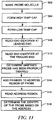
- a method for forming a membrane (e.g., lipid bilayer) for use in a nanopore sensor comprises (a) directing a buffer solution in flow channel comprising an electrode having a material layer thereon, wherein the buffer solution is electrically conductive, and wherein the material layer comprises one or more constituents of the membrane (e.g., lipids); (b) bringing the buffer solution in contact with the material layer; (c) measuring a current through the electrode to determine if at least a portion of the material layer has formed a membrane (e.g., lipid bilayer) over all or a portion of the electrode; and (d) based on the determination of (c), applying a stimulus to the electrode to induce the at least the portion of the material layer to form the membrane adjacent to the electrode.
- a buffer solution in flow channel comprising an electrode having a material layer thereon, wherein the buffer solution is electrically conductive, and wherein the material layer comprises one or more constituents of the membrane (e.g., lipids); (b)
- one or more voltages are applied to the electrodes in (c).
- the voltage is high enough to break the bilayer over the electrode.
- the stimulus is applied simultaneously to all the electrodes.
- the stimulus comprises at least one of a liquid flow over the surface of the electrode, a sequential flow of one or more different liquids over the surface of the electrode, the flow of one or more bubbles over the surface of the electrode, an electrical pulse, sonication pulse, pressure pulse, or sound pulse.
- the material layer comprising one or more porin proteins comprises one or more surfactants at a concentration less than the critical micelle concentration of the surfactant.
- the flow channel comprises a plurality of electrodes.
- the material layer comprises a lipid. In some cases, the material layer comprises at least two, three, four, five, or ten types of lipids.
- the material layer comprises a pore protein.
- the pore protein is mycobacterium smegmatis porin A (MspA), alpha-hemolysin, any protein having at least 70% homology to at least one of smegmatis porin A (MspA) or alpha-hemolysin, or any combination thereof.
- MspA mycobacterium smegmatis porin A
- MspA alpha-hemolysin
- any protein having at least 70% homology to at least one of smegmatis porin A (MspA) or alpha-hemolysin or any combination thereof.
- the method further comprises, after (d), applying an electrical stimulus through the electrode to facilitate the insertion of the pore protein in the membrane (e.g., lipid bilayer).
- an electrical stimulus through the electrode to facilitate the insertion of the pore protein in the membrane (e.g., lipid bilayer).
- the membrane and the pore protein together exhibit a resistance of about 1 G ⁇ or less.
- the membrane without a pore protein exhibits a resistance greater than about 1 G ⁇ .
- a pressure of the buffer solution is selected such that the material layer forms the membrane without the stimulus.
- the method further comprises, prior to (a), generating the material layer adjacent to the electrode.
- the generating operation comprises: directing a lipid solution comprising one or more lipids through the flow channel; and depositing the material layer on the electrode.
- the lipid solution comprises an organic solvent.
- the organic solvent comprises decane.
- the buffer solution comprises an ionic solution.
- the ionic solution comprises a chloride anion.
- the ionic solution comprises sodium acetate.
- the method further comprises, after (a): directing a bubble through the flow channel; and bringing the bubble in contact with the material layer to smooth and/or thin the material layer.
- the bubble is a vapor bubble.
- the method further comprises: flowing a pore protein solution adjacent to the material layer to deposit a pore protein in the material layer; and thinning the material layer with ionic solution and/or another bubble in the flow channel.
- lipids can be selected from the group consisting of diphytanoylphosphatidylcholine (DPhPC), palmitoyl-oleoyl-phosphatidyl-choline (POPC), dioleoyl-phosphatidyl-methylester (DOPME), dipalmitoylphosphatidylcholine (DPPC), phosphatidylcholine, phosphatidylethanolamine, phosphatidylserine, phosphatidic acid, phosphatidylinositol, phosphatidylglycerol and sphingomyelin.
- DPhPC diphytanoylphosphatidylcholine
- POPC palmitoyl-oleoyl-phosphatidyl-choline
- DOPME dioleoyl-phosphatidyl-methylester
- DPPC dipalmitoylphosphatidylcholine
- phosphatidylcholine phosphat
- a surface of the electrode that is exposed to the flow channel is hydrophilic.
- the electrode is disposed adjacent to one or more hydrophobic surfaces of the flow channel.
- the one or more hydrophobic surfaces are silanized.
- the flow channel is formed in a chip.
- the electrode is formed in a surface of the flow channel.
- the flow channel is sealed.
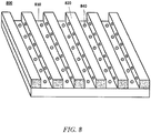
- the one or more flow channels comprise a plurality of flow channels.
- the plurality of flow channels are fluidically separated from one another with the aid of guide rails along the plurality of flow channels.
- the electrode is an individually addressable electrode.
- a method for forming a membrane (e.g., lipid bilayer) for use in a nanopore sensing device comprises: (a) providing a chip comprising a plurality of electrodes and material layers adjacent to the plurality of electrodes, wherein each of the material layers comprises one or more constituents (e.g., lipids) of the membranes; (b) contacting the material layers with a buffer solution, wherein the buffer solution is electrically conductive; (c) applying a stimulus to at least a subset of the plurality of electrodes to induce the material layers to form membranes adjacent to the plurality of the electrodes; and (d) repeating steps (b) and (c), as needed, until at least about 20% of the plurality of electrodes deactivate at a voltage pulse between about -100 millivolts (mV) and -1000 mV applied to the plurality of electrodes.
- mV millivolts
- the plurality of electrodes are each individually addressable.
- steps (b) and (c) are repeated as needed until at least about 60% of the plurality of electrodes deactivate at the applied voltage pulse.
- the applied voltage pulse is between about -400 mV and -700 mV.
- the stimulus comprises at least one of a liquid flow over the surface of the electrode, a sequential flow of one or more different liquids over the surface of the electrode, the flow of one or more bubbles over the surface of the electrode, an electrical pulse, sonication pulse, pressure pulse, or sound pulse.
- each of the material layers comprises a pore protein.
- the pore protein is mycobacterium smegmatis porin A (MspA), alpha-hemolysin, any protein having at least 70% homology to at least one of smegmatis porin A (MspA) or alpha-hemolysin, or any combination thereof.
- MspA mycobacterium smegmatis porin A
- MspA alpha-hemolysin
- any protein having at least 70% homology to at least one of smegmatis porin A (MspA) or alpha-hemolysin or any combination thereof.
- the method further comprises, after (c), applying an electrical stimulus through at least a subset of the electrodes to facilitate the insertion of the pore protein in each of the lipid bilayers.
- the method further comprises: contacting the plurality of electrodes with a lipid solution to form the material layers, wherein the lipid solution comprises the lipid.
- the lipid solution comprises an organic solvent.
- the organic solvent comprises decane.
- the buffer solution comprises an ionic solution.
- the ionic solution comprises a chloride anion.
- the ionic solution comprises sodium acetate.
- the method further comprises, between steps (a) and (b), directing a bubble adjacent to each of the material layers.
- the electrodes are sealed in one or more flow channels of the chip.
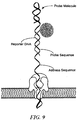
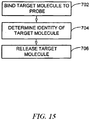
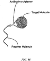
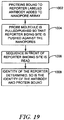
- a method for detecting a target molecule comprises: (a) providing a chip comprising a nanopore in a membrane that is disposed adjacent or in proximity to a sensing electrode; (b) directing a nucleic acid molecule through the nanopore, wherein the nucleic acid molecule is associated with a reporter molecule, wherein the nucleic acid molecule comprises an address region and a probe region, wherein the reporter molecule is associated with the nucleic acid molecule at the probe region, and wherein the reporter molecule is coupled to a target molecule; (c) sequencing the address region while the nucleic acid molecule is directed through the nanopore to determine a nucleic acid sequence of the address region; and (d) identifying, with the aid of a computer processor, the target molecule based upon a nucleic acid sequence of the address region determined in (c).
- the probe molecule in (b) is held in the pore by the binding of a reporter molecule to the probe region of the nucleic acid molecule.
- up to three bases of the nucleic acid molecule are identified when the rate of progression of the nucleic acid molecule through the nanopore is reduced.
- up to five bases of the nucleic acid molecule are identified when the rate of progression of the nucleic acid molecule through the nanopore is reduced.
- the rate of progression of the nucleic acid molecule through the nanopore is reduced upon the interaction of the reporter molecule with the nanopore.
- a rate of progression of the nucleic acid molecule through the nanopore is stopped or stalled.
- the method further comprises, prior to (d), determining whether a rate of progression of the nucleic molecule through the nanopore has been reduced.
- the target molecule is identified if it is determined that the rate of progression of the nucleic acid molecule through the nanopore has been reduced.
- the target molecule is identified based upon a correlation between (i) a nucleic acid sequence of the address region and an association and (ii) a rate of progression of the nucleic acid molecule through the nanopore.
- the nanopore is individually addressable.
- the nucleic acid molecule is single-stranded.
- the method further comprises trapping the nucleic acid molecule in the nanopore.
- the nucleic acid molecule is trapped in the nanopore with the aid of bulky structures formed at one or more end portions of the nucleic acid molecule.
- the nucleic acid molecule is trapped in the nanopore with the aid of bulky structures affixed to one or more end portions of the nucleic acid molecule.
- the method further comprises reversing a direction of flow of the nucleic acid molecule through the nanopore.
- the method further comprises re-sequencing at least a portion of the address region upon reversing the direction of flow of the nucleic acid molecule.
- the reporter molecule comprises an antibody or aptamer at an end portion of the reporter molecule, and wherein the antibody or aptamer is associated with the target molecule.
- address region and probe region have known nucleic acid sequences.
- the reporter molecule comprises a nucleic acid sequence that is complimentary to a nucleic acid sequence of the probe region.
- the nucleic acid molecule is associated with the reporter molecule prior to being directed through the.
- the nucleic acid molecule prior to (b), is threaded through the nanopore, and wherein, in (b), the reporter molecule is associated with the nucleic acid molecule that has been threaded through the nanopore.
- nanopore generally refers to a pore, channel or passage formed or otherwise provided in a membrane.
- a membrane may be an organic membrane, such as a lipid bilayer, or a synthetic membrane, such as a membrane formed of a polymeric material.
- the membrane may be a polymeric material.
- the nanopore may be disposed adjacent or in proximity to a sensing circuit or an electrode coupled to a sensing circuit, such as, for example, a complementary metal-oxide semiconductor (CMOS) or field effect transistor (FET) circuit.
- CMOS complementary metal-oxide semiconductor
- FET field effect transistor
- a nanopore has a characteristic width or diameter on the order of 0.1 nanometers (nm) to about 1000 nm.
- Some nanopores are proteins. Alpha hemolysin is an example of a protein nanopore.
- polymerase generally refers to any enzyme or other molecular catalyst that is capable of catalyzing a polymerization reaction.
- examples of polymerases include, without limitation, a nucleic acid polymerase or a ligase.
- a polymerase can be a polymerization enzyme.
- nucleic acid generally refers to a molecule comprising one or more nucleic acid subunits.
- a nucleic acid may include one or more subunits selected from adenosine (A), cytosine (C), guanine (G), thymine (T) and uracil (U), or variants thereof.
- a nucleotide can include A, C, G, T or U, or variants thereof.
- a nucleotide can include any subunit that can be incorporated into a growing nucleic acid strand.
- Such subunit can be an A, C, G, T, or U, or any other subunit that is specific to one or more complementary A, C, G, T or U, or complementary to a purine (i.e., A or G, or variant thereof) or a pyrimidine (i.e., C, T or U, or variant thereof).
- a subunit can enable individual nucleic acid bases or groups of bases (e.g., AA, TA, AT, GC, CG, CT, TC, GT, TG, AC, CA, or uracil-counterparts thereof) to be resolved.
- a nucleic acid is deoxyribonucleic acid (DNA) or ribonucleic acid (RNA), or variants or derivatives thereof.
- a nucleic acid may be single-stranded or double stranded.
- polynucleotide or "oligonucleotide,” as used herein, generally refers to a polymer or oligomer comprising one or more nucleotides.
- a polynucleotide or oligonucleotide may comprise a DNA polynucleotide or oligonucleotide, a RNA polynucleotide or oligonucleotide, or one or more sections of DNA polynucleotide or oligonucleotide and/or RNA polynucleotide or oligonucleotide.
- a "nucleotide” or “base” can be a primary nucleotide or a nucleotide analog.
- a primary nucleotide is deoxyadenosine mono-phosphate (dAMP), deoxycytidine mono-phosphate (dCMP), deoxyguanosine mono-phosphate (dGMP), deoxythymidine mono-phosphate (dTMP), adenosine mono-phosphate (AMP), cytidine mono-phosphate (CMP), guanosine mono-phosphate (GMP) or uridine mono-phosphate (UMP).
- dAMP deoxyadenosine mono-phosphate
- dCMP deoxycytidine mono-phosphate
- dGMP deoxythymidine mono-phosphate
- AMP adenosine mono-phosphate
- CMP cytidine mono-phosphate
- GMP guanosine mono-phosphate
- UMP uridine mono-phosphate
- a nucleotide analog is an analog or mimic of a primary nucleotide having modification on the primary nucleobase (A, C, G, T and U), the deoxyribose/ribose structure, the phosphate group of the primary nucleotide, or any combination thereof.
- a nucleotide analog can have a modified base, either naturally existing or man-made.
- modified bases include, without limitation, methylated nucleobases, modified purine bases (e.g. hypoxanthine, xanthine, 7-methylguanine, isodG), modified pyrimidine bases (e.g. 5,6-dihydrouracil and 5-methylcytosine, isodC), universal bases (e.g.
- nucleotide analogs having modified deoxyribose e.g. dideoxynucleosides such as dideoxyguanosine, dideoxyadenosine, dideoxythymidine, and dideoxycytidine
- phosphate structure (together referred to as the backbone structure) includes, without limitation, glycol nucleotides, morpholinos, and locked nucleotides.
- test polymer generally refers to a polymer molecule that passes through or adjacent to a nanopore for detection purposes.
- the test polymer may comprise multiple building blocks that have similar chemical structures.
- test polymers include, without limitation, test polynucleotides, test peptides/proteins, and test carbohydrates.
- a test polynucleotide can be a single-stranded test polynucleotide (i.e., ss test polynucleotide) or a double-stranded test polynucleotide (i.e., ds test polynucleotide).
- building blocks include, without limitation, nucleotides, amino acids, and monosaccharides.
- sample polynucleotide generally refers to a nucleic acid molecule which can comprise a polynucleotide of interest, such as, for example, a single-stranded (“ss”) sample polynucleotide (ss sample polynucleotide) or a double-stranded (“ds”) sample polynucleotide (i.e., ds sample polynucleotide, such as, e.g. ds sample DNA, ds sample RNA, and ds sample DNA-RNA hybrid).
- ss sample polynucleotide such as, e.g. ds sample DNA, ds sample RNA, and ds sample DNA-RNA hybrid.
- a sample polynucleotide can be a natural polynucleotide obtained from a biological sample or a synthetic polynucleotide.
- the synthetic polynucleotide may be a polynucleotide obtained by modification of a natural polynucleotide, such as pre-processed polynucleotide intended for use in polynucleotide identification and/or sequencing.
- pre-processings include, without limitation, enrichment of the sample polynucleotide for desired fragments, paired-end processing, mated pair read processing, epigenetic pre-processing including bisulfide treatment, focused fragment analysis via PCR, PCR fragment sequencing, and short polynucleotide fragment analysis.
- test polynucleotide generally refers to a polynucleotide molecule that passes through or adjacent to a nanopore for detection purposes.
- a test polynucleotide can be a single-stranded test polynucleotide (i.e., ss test polynucleotide) and a double-stranded test polynucleotide (i.e., ds test polynucleotide, such as, e.g. ds test DNA, ds test RNA, and ds test DNA-RNA hybrid).
- a ss test polynucleotide as used herein, comprises a section of ss polynucleotide that is to be bound by a speed bump in a method described herein.
- a ss test polynucleotide may further comprise a sample polynucleotide and other functional moieties (e.g., pre-bulky structure, identifiers and isolation tags).
- pre-bulky structure generally refers to a molecular structure in a polynucleotide molecule which can form a bulky structure under certain conditions (e.g., at certain temperature, presence/absence of certain compound(s)).
- pre-bulky structures include oligonucleotide structures.
- a pre-bulky structure can be a ss polynucleotide or a ds polynucleotide.
- the term "bulky structure”, as used herein, generally refers to a structure (e.g., nucleotide) formed from a pre-bulky structure in a ss test polynucleotide molecule.
- the bulky structure can slow or stall the test polynucleotide molecule in a nanopore at a working condition until the working condition is changed to another condition wherein the bulky structure is converted to the pre-bulky structure or other structures that may stall the test polynucleotide molecule.
- Examples of bulky structures include, without limitation, 2-D and 3-D structures such as polynucleotide duplex structures (RNA duplex, DNA duplex or RNA-DNA hybrid), polynucleotide hairpin structures, multi-hairpin structures and multi-arm structures.
- the pre-bulky structure forms a bulky structure via interaction with a ligand specific to the pre-bulky structure. Examples of such pre-bulky structure/ligand pair include, without limitation, biotin/streptavidin, antigen/antibody, and carbohydrate/antibody.
- the bulky structure is formed from an oligonucleotide pre-bulky structure, e.g., an oligonucleotide structure formed from a pre-bulky structure in a ss test polynucleotide molecule.
- polynucleotide or oligonucleotide bulky structures include, without limitation, hairpin nucleic acid strands, hybridized antisense nucleic acid strands, multiple arms and three dimensional DNA or RNA molecules that are self-hybridized.
- the bulky structure is formed via interactions of a pre-bulky structure/ligand pair as described herein.
- duplex generally refers to a duplex structure, section, region or segment.
- a duplex can include an RNA duplex, DNA duplex or a DNA-RNA duplex structure, section, region or segment.
- speed bump generally refers to a molecule, such as an oligonucleotide, that forms a complex with a binding segment of a test polynucleotide molecule.
- a test polynucleotide molecule travels through or adjacent to a nanopore under an applied electric potential
- the complex formed between a speed bump and the binding segment slows or stalls the test polynucleotide molecule in or adjacent to the nanopore for a dwelling time long enough for the nanopore detector to obtain a signal from the test polynucleotide molecule, which signal can provide structure or sequence information for the test polynucleotide molecule.
- the complex dissociates and the test polynucleotide molecule moves forward through the nanopore.
- known speed bump generally refers to a speed bump that specifically binds to a known sequence in a ss test polynucleotide. Because the binding segment on the ss test polynucleotide (the known sequence) is known, the speed bump structure can also be known (e.g. complementary to the known sequence on the ss test polynucleotide).
- random speed bump pool generally refers to a collection of speed bumps that can bind to all or substantially all sections of a test polynucleotide molecule or a fragment thereof.
- An example of random speed bump pool comprises oligonucleotides having universal nucleobases which base-pair with all primary nucleobases (A, T, C, G and U).
- Another example of random speed bump pool comprises oligonucleotides of a given length having all possible combinations of primary nucleobases.
- Another example of random speed bump pool comprises oligonucleotides of a given length having every possible combination of primary nucleobases and universal nucleobases.
- random speed bump pool comprises speed bumps having universal nucleobases at designated positions and all combinations of primary nucleobases at the other positions.
- Another example of random speed bumps is a combination of ss speed bumps, which form duplex sections with ss test polynucleotide, and the duplex sections have about the same melting temperatures. These ss speed bumps may have the same or different lengths, and/or the same or different nucleotides.
- stopper generally refers to a structure that can form a stopper-test polynucleotide complex with the test polynucleotide and stop the flow of the stopper-test polynucleotide complex before the constriction area of the nanopore for the dwelling time.
- the stopper can be part of the test polynucleotide, or a separate structure (e.g. a speed bump described herein, and an antisense strand of the test polynucleotide formed in the presence of a nucleotide polymerase), or an enzyme that can bind to the test polynucleotide and, in some cases, move the test polynucleotide through the nanopore.
- identifier generally refers to a known sequence or structure in a test polynucleotide that can be detected or identified by the method described herein.
- identifiers include, without limitation, direction identifiers, reference signal identifiers, sample source identifiers, and sample identifiers.
- the identifiers may comprise one or more nucleotides or structures that provide distinctive electrical signals that are identifiable. Examples of such nucleotides and structures include, without limitation, isodG, isodC, methylated nucleotides, locked nucleic acids, universal nucleotides, and abasic nucleotides.
- an abasic nucleotide provides a stronger signal than a primary nucleotide.
- the electrical signal detected by a nanopore for a sequence comprising both abasic nucleotides and primary nucleotides may provide a signal more intense than the electrical signal obtained from primary nucleotide only sequences.
- a 4 to 5 base sequence comprising about 25% abasic nucleotides may provide a signal more than twice as strong as a 4 to 5 base sequence comprising only primary nucleotides. The more abasic nucleotides the sequence have, the stronger electrical signal the sequence.
- identifiers may provide electrical signals of a desired intensity (e.g., about twice, about 3, 4, 5, 6, 7, 8, 9, or about 10 times stronger than that of primary oligonucleotides having the same length) by changing the amount of abasic nucleotides in the identifier sequences.
- a desired intensity e.g., about twice, about 3, 4, 5, 6, 7, 8, 9, or about 10 times stronger than that of primary oligonucleotides having the same length
- direction identifier generally refers to a known sequence positioned at least 0, 1, 2, 3, 4, 5, 6, 7, 8, 9, 10, 11, 12, 13, 14, 15, 16, 17, 18, 19, 20, or 50 bases from a bulky structure formed from a pre-bulky structure (the shaded section in the ss test polynucleotide molecule as depicted in Figure 17 ).
- a bulky structure when a bulky structure is formed, it can stop a ss test polynucleotide molecule from flowing through a nanopore within which the ss test polynucleotide molecule is incorporated.
- a set of electrical signals may be obtained, which can provide sequence information of the sequence that is in front of the bulky structure and the first base pair of the bulky structure, in the flow direction of the ss test polynucleotide molecule.
- such electrical signals can, without limitation: (1) verify that the pre-bulky structure has properly formed into the bulky structure such that the bulky structure stops the ss test polynucleotide molecule from flowing through the nanopore; (2) indicate that the ss test polynucleotide molecule has reached one end of the single strand section of the ss test polynucleotide, and/or (3) serve as a reference or calibration read to base line other electrical signals obtained in the same nanopore.
- the direction identifier comprises one or more nucleotides or structures that provide distinctive electrical signals that are readily identified. Examples of such nucleotides and structures include, without limitation, isodG, isodC and abasic nucleotides.
- reference signal identifier generally refers to a known sequence in a test polynucleotide, which when detected or identified by the methods described herein, can serve as a reference or calibration read to base line other electrical signals obtained in the same nanopore.
- sample source identifier generally refers to a known sequence in a test polynucleotide, which when detected or identified by the methods described herein, can be used to identify the source of the sample polynucleotide.
- sample identifier generally refers to a known sequence in a test polynucleotide, which when detected or identified by the methods described herein, can be used to identify the individual sample polynucleotide.
- linker identifier generally refers to a known sequence in a test polynucleotide, which when detected or identified by the methods described herein, can be used to indicate the transition between the sample polynucleotide section and the antisense polynucleotide section. In an example, when the linker identifier is detected or identified, the sample/antisense polynucleotide section has passed through the nanopore.
- Probe source identifier is a known sequence in a probe polynucleotide, when detected or identified by the method described herein, is used to identify the source that the probe polynucleotide is from.
- Probe identifier is a known sequence in a probe polynucleotide, when detected or identified by the method described herein, is used to identify the individual sample polynucleotide.
- the "Binding Site for Reporter Molecule” section binds to a reporter molecule as described herein.
- the reporter molecule comprises DNA, RNA or any combinations thereof.
- Reporter identifier is a known sequence in a probe polynucleotide, when detected or identified by the method described herein, is used to indicate the binding of reporter molecule to the probe polynucleotide.
- a method for identifying a species, such as a molecule or portion thereof, with a nanopore can comprise providing a biochip (also "chip” herein) comprising at least one nanopore in a membrane that is disposed adjacent or in proximity to an electrode.
- the electrode can be adapted to detect a current passing through the nanopore.
- the method can further include inserting a molecule or portion thereof into the nanopore and varying a voltage applied across the nanopore and/or across the membrane.
- the method includes measuring the current at a plurality of voltages to identify the molecule or portion thereof.
- the current at a plurality of voltages comprises an electronic signature and further comprises comparing the electronic signature to a plurality of reference electronic signatures to identify the molecule or portion thereof.
- the nanopore may be formed or otherwise embedded in a membrane disposed adjacent to a sensing electrode of a sensing circuit, such as an integrated circuit.
- the integrated circuit may be an application specific integrated circuit (ASIC).
- the integrated circuit is a field effect transistor or a complementary metal-oxide semiconductor (CMOS).
- CMOS complementary metal-oxide semiconductor
- the sensing circuit may be situated in a chip or other device having the nanopore, or off of the chip or device, such as in an off-chip configuration.
- the semiconductor can be any semiconductor, including, without limitation, Group IV (e.g., silicon) and Group III-V semiconductors (e.g., gallium arsenide).
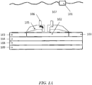
- FIG. 1 shows an example of a nanopore detector (or sensor) having temperature control, as may be prepared according to methods described in U.S. Patent Application Publication No. 2011/0193570 .
- the nanopore detector comprises a top electrode 101 in contact with a conductive solution (e.g., salt solution) 107.
- a bottom conductive electrode 102 is near, adjacent, or in proximity to a nanopore 106, which is inserted in a membrane 105.
- the bottom conductive electrode 102 is embedded in a semiconductor 103 in which is embedded electrical circuitry in a semiconductor substrate 104.
- a surface of the semiconductor 103 may be treated to be hydrophobic.
- a sample being detected goes through the pore in the nanopore 106.
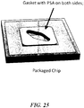
- the semiconductor chip sensor is placed in package 208 and this, in turn, is in the vicinity of a temperature control element 109.
- the temperature control element 109 may be a thermoelectric heating and/or cooling device (e.g., Peltier device).
- the bilayer spans and covers the electrode 202.
- a nanopore array can include one or more nanopore detectors. In some cases, a nanopore array includes at least 1, 2, 3, 4, 5, 6, 7, 8, 9, 10, 100, 1000, 10000, or 100,000 nanopore detectors.
- An individual nanopore detector can include one or more nanopores adjacent to a sensing electrode (e.g., bottom conductive electrode 102 ). In some cases, an individual nanopore detector includes at least 1, 2, 3, 4, 5, 6, 7, 8, 9, 10, or 100 nanopores adjacent to a sensing electrode.
- the membrane 105 can be disposed over a well 110, where the sensor 102 forms part of the surface of the well.
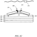
- Figure 1C shows an example in which the electrode 102 protrudes from the treated semiconductor surface 103.
- the membrane 105 forms on the bottom conductive electrode 102 and not on the semiconductor 103.
- the membrane 105 in such a case may form coupling interactions with the bottom conductive electrode 102. In some cases, however, the membrane 105 forms on the bottom conductive electrode 102 and the semiconductor 103.
- the membrane 105 can form on the semiconductor 103 and not on the bottom conductive electrode 102, but may extend over the bottom conductive electrode 102.
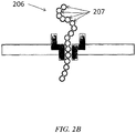
- Figure 2 shows some examples of molecules that can be detected and methods for sequencing polymers including nucleic acids.
- the molecule 201 passes through the nanopore 202 from the cis side 203 (away from the electrode) to the trans side 204 (toward to the electrode) of the membrane 205.
- the molecule can be a polymer molecule 206 and portions of the polymer molecule 207 can be identified as the polymer molecule passes through the nanopore.
- the polymer molecule can be a biological molecule such as a nucleic acid or a protein.
- the polymer molecule is a nucleic acid and the portions of the polymer molecule are nucleic acids or groups of nucleic acids (e.g., 2, 3, 4, 5, 6, 7, or 8 nucleic acids).
- the polymer molecule is a polypeptide and the portions of the polypeptide are amino acids or groups of nucleic acids (e.g., 2, 3, 4, 5, 6, 7, or 8 amino acids).
- the sensing circuit detects an electrical signal associated with the nucleic acid or tag.
- the nucleic acid may be a subunit of a larger strand.
- the tag may be a byproduct of a nucleotide incorporation event or other interaction between a tagged nucleic acid and the nanopore or a species adjacent to the nanopore, such as an enzyme that cleaves a tag from a nucleic acid.
- the tag may remain attached to the nucleotide.
- a detected signal may be collected and stored in a memory location, and later used to construct a sequence of the nucleic acid. The collected signal may be processed to account for any abnormalities in the detected signal, such as errors.
- the molecule 208 (e.g., a "tag molecule”) is bound to a nucleotide 209.
- the molecule can be identified while the nucleotide is being incorporated into a growing nucleic acid chain 210 (e.g., by a polymerase 211 ).
- the nucleotide can be incorporated according to base pair matching with a template nucleic acid 212. If different tags are bound to each of the different nucleotides (e.g., A, C, T and G), the sequence of the template nucleic acid can be determined by detecting the tag molecules with the nanopore (e.g., without the template nucleic acid passing through the nanopore).
- the molecule is released 213 from the nucleotide upon incorporation of the nucleotide into a growing nucleic acid chain. As shown in Figure 2D , the molecule can be detected while the nucleotide is being incorporated into the growing strand and/or before being released from the nucleotide 214. In some cases, the address region of the probe or reporter region is sequenced using tags.
- FIG. 3 schematically illustrates a nanopore device 300 (or sensor) that may be used to detect a molecule(and/or sequence a nucleic acid) as described herein.
- the nanopore containing lipid bilayer may be characterized by a resistance and capacitance.
- the nanopore device 300 includes a lipid bilayer 302 formed on a lipid bilayer compatible surface 304 of a conductive solid substrate 306, where the lipid bilayer compatible surface 304 may be isolated by lipid bilayer incompatible surfaces 305 and the conductive solid substrate 306 may be electrically isolated by insulating materials 307, and where the lipid bilayer 302 may be surrounded by amorphous lipid 303 formed on the lipid bilayer incompatible surface 305.
- the lipid bilayer 302 may be embedded with a single nanopore structure 308 having a nanopore 310 large enough for passing of the molecules being detected and/or small ions (e.g., Na + , K + , Ca 2+ , Cl -" ) between the two sides of the lipid bilayer 302.
- a layer of water molecules 314 may be adsorbed on the lipid bilayer compatible surface 304 and sandwiched between the lipid bilayer 302 and the lipid bilayer compatible surface 304.
- the aqueous film 314 adsorbed on the hydrophilic lipid bilayer compatible surface 304 may promote the ordering of lipid molecules and facilitate the formation of lipid bilayer on the lipid bilayer compatible surface 304.
- a sample chamber 316 containing a solution of the molecule to be detected (e.g., nucleic acid molecule, in some cases with tagged nucleotides or other components as needed) 312 may be provided over the lipid bilayer 302.
- the solution may be an aqueous solution containing electrolytes and buffered to an optimum ion concentration and maintained at an optimum pH to keep the nanopore 310 open.
- the device includes a pair of electrodes 318 (including a negative node 318a and a positive node 318b) coupled to a variable voltage source 320 for providing electrical stimulus (e.g., voltage bias) across the lipid bilayer and for sensing electrical characteristics of the lipid bilayer (e.g., resistance, capacitance, and ionic current flow).
- the surface of the positive electrode 318b is or forms a part of the lipid bilayer compatible surface 304.
- the conductive solid substrate 306 may be coupled to or forms a part of one of the electrodes 318.
- the device 300 may also include an electrical circuit 322 for controlling electrical stimulation and for processing the signal detected.
- the (e.g., variable) voltage source 320 is included as a part of the electrical circuit 322.
- the electrical circuitry 322 may include amplifier, integrator, noise filter, feedback control logic, and/or various other components.
- the electrical circuitry 322 may be integrated electrical circuitry integrated within a silicon substrate 328 and may be further coupled to a computer processor 324 coupled to a memory 326.
- the lipid bilayer compatible surface 304 may be formed from various materials that are suitable for ion transduction and gas formation to facilitate lipid bilayer formation.
- conductive or semi-conductive hydrophilic materials may be used because they may allow better detection of a change in the lipid bilayer electrical characteristics.
- Example materials include Ag-AgCl, Au, Pt, or doped silicon or other semiconductor materials.
- the electrode is not a sacrificial electrode.
- the lipid bilayer incompatible surface 305 may be formed from various materials that are not suitable for lipid bilayer formation and they are typically hydrophobic. In some embodiments, non-conductive hydrophobic materials are preferred, since it electrically insulates the lipid bilayer regions in addition to separate the lipid bilayer regions from each other.
- Example lipid bilayer incompatible materials include for example silicon nitride ( e.g. , Si 3 N 4 ) and Teflon, silicon oxide (e.g., SiO 2 ) silanized with hydrophobic molecules.
- the nanopore device 300 of Figure 3 is a alpha hemolysin (aHL) nanopore device having a single alpha hemolysin (aHL) protein 308 embedded in a diphytanoylphosphatidylcholine (DPhPC) lipid bilayer 302 formed over a lipid bilayer compatible silver (Ag) surface 304 coated on an aluminum material 306.
- the lipid bilayer compatible Ag surface 304 is isolated by lipid bilayer incompatible silicon nitride surfaces 305, and the aluminum material 306 is electrically insulated by silicon nitride materials 307.
- the aluminum 306 is coupled to electrical circuitry 322 that is integrated in a silicon substrate 328.
- a silver-silver chloride electrode placed on-chip or extending down from a cover plate 328 contacts an aqueous solution containing (e.g., nucleic acid) molecules.
- the aHL nanopore is an assembly of seven individual peptides.
- the entrance or vestibule of the aHL nanopore is approximately 26 Angstroms in diameter, which is wide enough to accommodate a portion of a dsDNA molecule.
- the aHL nanopore first widens and then narrows to a barrel having a diameter of approximately 15 Angstroms, which is wide enough to allow a single ssDNA molecule (or smaller tag molecules) to pass through but not wide enough to allow a dsDNA molecule (or larger tag molecules) to pass through.
- the lipid bilayer of the nanopore device may be assembled from various other suitable amphiphilic materials, selected based on various considerations, such as the type of nanopore used, the type of molecule being characterized, and various physical, chemical and/or electrical characteristics of the lipid bilayer formed, such as stability and permeability, resistance, and capacitance of the lipid bilayer formed.
- Example amphiphilic materials include various phospholipids such as palmitoyl-oleoyl- phosphatidyl-choline (POPC) and dioleoyl-phosphatidyl-methylester (DOPME), diphytanoylphosphatidylcholine (DPhPC) dipalmitoylphosphatidylcholine (DPPC), phosphatidylcholine, phosphatidylethanolamine, phosphatidylserine, phosphatidic acid, phosphatidylinositol, phosphatidylglycerol, and sphingomyelin.
- POPC palmitoyl-oleoyl- phosphatidyl-choline
- DOPME dioleoyl-phosphatidyl-methylester
- DPhPC diphytanoylphosphatidylcholine
- DPPC dipalmitoylphosphatidylcholine
- the nanopore may be of various other types of nanopores. Examples include ⁇ -hemolysin, leukocidin, melittin, mycobacterium smegmatis porin A (MspA) and various other naturally occurring, modified natural, and synthetic nanopores.
- a suitable nanopore may be selected based on various characteristics of the analyte molecule such as the size of the analyte molecule in relation to the pore size of the nanopore. For example, the aHL nanopore that has a restrictive pore size of approximately 15 Angstroms.
- current may be measured at different applied voltages.
- a desired potential may be applied to the electrode, and the applied potential may be subsequently maintained throughout the measurement.
- an opamp integrator topology may be used for this purpose as described herein.
- the integrator maintains the voltage potential at the electrode by means of capacitive feedback.
- the integrator circuit may provide outstanding linearity, cell-to-cell matching, and offset characteristics.
- the opamp integrator typically requires a large size in order to achieve the required performance. A more compact integrator topology is described herein.
- a voltage potential "Vliquid” may be applied to the chamber which provides a common electrical potential (e.g., 350 mV) for all of the cells on the chip.
- the integrator circuit may initialize the electrode (which is electrically the top plate of the integrating capacitor) to a potential greater than the common liquid potential. For example, biasing at 450 mV may give a positive 100 mV potential between electrode and liquid. This positive voltage potential may cause a current to flow from the electrode to the liquid chamber contact.
- the carriers are: (a) K+ ions which flow through the pore from the electrode (trans) side of the bi-layer to the liquid reservoir (cis) side of the bi-layer and (b) chlorine (Cl-) ions on the trans side which reacts with the silver electrode according to the following electro-chemical reaction: Ag + Cl- ⁇ AgCl + e-.
- K+ flows out of the enclosed cell (from trans to cis side of bi-layer) while Cl- is converted to silver chloride.
- the electrode side of the bilayer may become desalinated as a result of the current flow.
- a silver/silver-chloride liquid spongy material or matrix may serve as a reservoir to supply Cl- ions in the reverse reaction which occur at the electrical chamber contact to complete the circuit.
- Electrodes ultimately flow onto the top side of the integrating capacitor which creates the electrical current that is measured.
- the electrochemical reaction converts silver to silver chloride and current will continue to flow only as long as there is available silver to be converted.
- the limited supply of silver leads to a current dependent electrode life in some cases.
- electrode materials that are not depleted e.g., platinum are used.
- FIG. 4 An example of cell circuitry is shown in Figure 4 .
- An applied voltage Va is applied to an opamp 1200 ahead of a MOSFET current conveyor gate 401. Also shown here are an electrode 402 and the resistance of the nucleic acid and/or tag detected by the device 403.
- An applied voltage Va can drive the current conveyor gate 401.
- the resulting voltage on the electrode sis then Va-Vt where Vt is the threshold voltage of the MOSFET.
- Vt is the threshold voltage of the MOSFET.
- this results in limited control of the actual voltage applied to the electrode as a MOSFET threshold voltage can vary considerably over process, voltage, temperature, and even between devices within a chip.
- This Vt variation can be greater at low current levels where sub-threshold leakage effects can come into play. Therefore, in order to provide better control of the applied voltage, an opamp can be used in a follower feedback configuration with the current conveyor device. This ensures that the voltage applied to the electrode is Va, independent of variation of the MOSFET threshold voltage.
- each nanopore location (e.g., 501 ) comprises a nanopore, which in some cases can be attached to a polymerase enzyme and/or phosphatase enzymes.
- a sensor at each array location as described herein.
- an array of nanopores attached to a nucleic acid polymerase is provided, and tagged nucleotides are incorporated with the polymerase.
- a tag is detected by the nanopore (e.g., by releasing and passing into or through the nanopore, or by being presented to the nanopore).
- the array of nanopores may have any suitable number of nanopores.
- the array comprises about 200, about 400, about 600, about 800, about 1000, about 1500, about 2000, about 3000, about 4000, about 5000, about 10000, about 15000, about 20000, about 40000, about 60000, about 80000, about 100000, about 200000, about 400000, about 600000, about 800000, about 1000000, and the like nanopores.
- the array comprises at least 200, at least 400, at least 600, at least 800, at least 1000, at least 1500, at least 2000, at least 3000, at least 4000, at least 5000, at least 10000, at least 15000, at least 20000, at least 40000, at least 60000, at least 80000, at least 100000, at least 200000, at least 400000, at least 600000, at least 800000, or at least 1000000 nanopores.
- the array of nanopore detectors may have a high density of discrete sites. For example, a relatively large number of sites per unit area (i.e., density) allows for the construction of smaller devices, which are portable, low-cost, or have other advantageous features.
- An individual site in the array can be an individually addressable site.
- a large number of sites comprising a nanopore and a sensing circuit may allow for a relatively large number of nucleic acid molecules to be sequenced at once, such as, for example, through parallel sequencing. Such a system may increase the through-put and/or decrease the cost of sequencing a nucleic acid sample.
- the surface comprises any suitable density of discrete sites (e.g., a density suitable for sequencing a nucleic acid sample in a given amount of time or for a given cost). Each discrete site can include a sensor.
- the surface may have a density of discrete sites greater than or equal to about 500 sites per 1 mm 2 . In some embodiments, the surface has a density of discrete sites of about 200, about 300, about 400, about 500, about 600, about 700, about 800, about 900, about 1000, about 2000, about 3000, about 4000, about 5000, about 6000, about 7000, about 8000, about 9000, about 10000, about 20000, about 40000, about 60000, about 80000, about 100000, or about 500000 sites per 1 mm 2 .
- the surface has a density of discrete sites of at least 200, at least 300, at least 400, at least 500, at least 600, at least 700, at least 800, at least 900, at least 1000, at least 2000, at least 3000, at least 4000, at least 5000, at least 6000, at least 7000, at least 8000, at least 9000, at least 10000, at least 20000, at least 40000, at least 60000, at least 80000, at least 100000, or at least 500000 sites per 1 mm 2 .
- a test chip includes an array of 264 sensors arranged in four separate groups (aka banks) of 66 sensor cells each. Each group is in turn divided into three “columns” with 22 sensors “cells” in each column.
- the "cell” name is apropos given that ideally a virtual cell comprising a bi-lipid layer and inserted nanopore is formed above each of the 264 sensors in the array (although the device may operate successfully with only a fraction of the sensor cells so populated).
- Figure 6 shows a system 600 comprising a computer system 601 coupled to a nanopore detection and/or nucleic acid sequencing system 602.
- the computer system 601 may be a server or a plurality of servers.
- the computer system 601 may be programmed to regulate sample preparation and processing, and nucleic acid sequencing by the sequencing system 602.
- the nanopore detection and/or sequencing system 602 may be a nanopore-based sequencer (or detector), as described herein.
- the computer system may be programmed to implement the methods of the disclosure.
- the computer system 601 includes a central processing unit (CPU, also "processor” herein) 605, which can be a single core or multi core processor, or a plurality of processors for parallel processing.
- the processor 605 can be part of a circuit, such as an integrated circuit. In some examples, the processor 605 can be integrated in an application specific integrated circuit (ASIC).
- the computer system 601 also includes memory 610 (e.g., random-access memory, read-only memory, flash memory), electronic storage unit 615 (e.g., hard disk), communications interface 620 (e.g., network adapter) for communicating with one or more other systems, and peripheral devices 625, such as cache, other memory, data storage and/or electronic display adapters.
- memory 610 e.g., random-access memory, read-only memory, flash memory
- electronic storage unit 615 e.g., hard disk
- communications interface 620 e.g., network adapter
- the memory 610, storage unit 615, interface 620 and peripheral devices 625 are in communication with the CPU 605 through a communications bus (solid lines), such as a motherboard.
- the storage unit 615 can be a data storage unit (or data repository) for storing data.
- the computer system 601 may be operatively coupled to a computer network ("network") with the aid of the communications interface 620.
- the network can be the Internet, an internet and/or extranet, or an intranet and/or extranet that is in communication with the Internet.
- the network can include one or more computer servers, which can enable distributed computing.
- the computer system 601 includes a field-programmable gate array (FPGA).
- the processor 605 in such a case may be excluded.
- Methods of the disclosure can be implemented by way of machine (or computer processor) executable code (or software) stored on an electronic storage location of the computer system 601, such as, for example, on the memory 610 or electronic storage unit 615.
- the code can be executed by the processor 605.
- the code can be retrieved from the storage unit 615 and stored on the memory 610 for ready access by the processor 605.
- the electronic storage unit 615 can be precluded, and machine-executable instructions are stored on memory 610.
- the code can be pre-compiled and configured for use with a machine have a processer adapted to execute the code, or can be compiled during runtime.
- the code can be supplied in a programming language that can be selected to enable the code to execute in a pre-compiled or as-compiled fashion.
- the computer system 601 can be adapted to store user profile information, such as, for example, a name, physical address, email address, telephone number, instant messaging (IM) handle, educational information, work information, social likes and/or dislikes, and other information of potential relevance to the user or other users.
- user profile information such as, for example, a name, physical address, email address, telephone number, instant messaging (IM) handle, educational information, work information, social likes and/or dislikes, and other information of potential relevance to the user or other users.
- profile information can be stored on the storage unit 615 of the computer system 601.
- the nanopore detection and/or nucleic acid sequencing system 602 can be directly coupled to the computer system 601 or go through the cloud (e.g., internet) 630.
- aspects of the systems and methods provided herein can be embodied in programming.
- Various aspects of the technology may be thought of as “products” or “articles of manufacture” typically in the form of machine (or processor) executable code and/or associated data that is carried on or embodied in a type of machine readable medium.
- Machine-executable code can be stored on an electronic storage unit, such memory (e.g., ROM, RAM) or a hard disk.
- “Storage” type media can include any or all of the tangible memory of the computers, processors or the like, or associated modules thereof, such as various semiconductor memories, tape drives, disk drives and the like, which may provide non-transitory storage at any time for the software programming.
- All or portions of the software may at times be communicated through the Internet or various other telecommunication networks. Such communications, for example, may enable loading of the software from one computer or processor into another, for example, from a management server or host computer into the computer platform of an application server.
- another type of media that may bear the software elements includes optical, electrical and electromagnetic waves, such as used across physical interfaces between local devices, through wired and optical landline networks and over various air-links.
- the physical elements that carry such waves, such as wired or wireless links, optical links or the like, also may be considered as media bearing the software.
- terms such as computer or machine "readable medium” refer to any medium that participates in providing instructions to a processor for execution.
- a machine readable medium such as computer-executable code
- a tangible storage medium such as computer-executable code
- Non-volatile storage media include, for example, optical or magnetic disks, such as any of the storage devices in any computer(s) or the like, such as may be used to implement the databases, etc. shown in the drawings.
- Volatile storage media include dynamic memory, such as main memory of such a computer platform.
- Tangible transmission media include coaxial cables; copper wire and fiber optics, including the wires that comprise a bus within a computer system.
- Carrier-wave transmission media may take the form of electric or electromagnetic signals, or acoustic or light waves such as those generated during radio frequency (RF) and infrared (IR) data communications.
- RF radio frequency
- IR infrared
- Common forms of computer-readable media therefore include for example: a floppy disk, a flexible disk, hard disk, magnetic tape, any other magnetic medium, a CD-ROM, DVD or DVD-ROM, any other optical medium, punch cards paper tape, any other physical storage medium with patterns of holes, a RAM, a ROM, a PROM and EPROM, a FLASH-EPROM, any other memory chip or cartridge, a carrier wave transporting data or instructions, cables or links transporting such a carrier wave, or any other medium from which a computer may read programming code and/or data.
- Many of these forms of computer readable media may be involved in carrying one or more sequences of one or more instructions to a processor for execution.
- lipid bilayers and nanopores on an array of electrodes e.g., individually controlled
- the chip can be used for determining polymer sequence such as nucleic acid sequence.
- liquids containing lipid molecules are inserted to the surface of the chip.
- the liquids are separated by bubbles.
- the lipid molecules can be distributed on the surface and the bubbles thin out the lipids to spontaneously form a lipid bilayer over each of the electrodes.
- Additional electrical stimulus may be applied to the electrodes to facilitate the bilayer formation.
- Solutions containing nanopore protein may be further applied on top of the deposited lipids. More bubbles may be rolled across the chip to facilitate the nanopore insertion into the bilayers. These techniques may occur with or without flow cells.
- additional stimulus can be applied to induce bilayer or pore creation including, pressure, sonication, and/or sound pulses.
- a method for forming a lipid bilayer for use in a nanopore sensor comprises: (a) directing a buffer solution in flow channel comprising an electrode having a material layer thereon.
- the buffer solution can be electrically conductive, and the material layer can comprise one or more lipids.
- the method can comprise bringing the buffer solution in contact with the material layer, and applying one or more voltages to the electrodes and measuring a current through the electrodes to determine if at least a portion of the material layer has covered and sealed the electrodes and/or formed a bilayer over all or a portion of the electrode.
- the applied voltage may be sufficient to break the bilayer seal over the electrode and cause short circuit current flow.
- a stimulus may be applied simultaneously to all the electrodes, groups of the electrodes, or individual electrodes to induce the at least the portion of the material layer to form the lipid bilayer adjacent to the electrode.
- the stimulus comprises at least one of a liquid flow over the surface of the electrode array, the sequential flow of one or more different liquids over the surface of the array, the sequential flow of any combination of one or more different liquids and bubbles over the surface of the array, an electrical pulse, sonication pulse, pressure pulse, or sound pulse.
- the material layer comprises at least two types of lipids.
- the material layer comprises a pore protein.
- the pore protein is mycobacterium smegmatis porin A (MspA) and/or alpha-hemolysin or a derivative of thereof with at least 70% homology to the amino acid sequence.
- the material layer comprising one or more porin proteins includes one or more surfactants at a concentration less than the surfactant's critical micelle concentration.
- the stimulus comprises at least one of a liquid flow over the surface of the electrode array, the sequential flow of one or more different liquids over the surface of the array, the sequential flow of any combination of one or more different liquids and bubbles over the surface of the array, an electrical pulse, sonication pulse, pressure pulse, or sound pulse.
- an automated method for creating a lipid bilayer on top of each one of multiple electrodes that make up an array of individually controlled electrodes and a method to insert a single pore into each bilayer atop each electrode in an array of individually controlled electrodes on a semiconductor sensor is described.
- an appropriate external stimulus e.g., electrical stimulus, pressure stimulus, sonication, or sound
- a bilayer can be induced to form over the electrode in an array of electrodes.
- an appropriate external stimulus e.g., including electrical stimulus, pressure stimulus, sonication, or sound
- an individual electrode to the entire sensor chip that has lipid bilayers on one or more electrodes and that are covered with a solution containing nanopore proteins
- a pore may be induced to insert into the bilayer.
- an appropriate external stimulus e.g., including electrical stimulus, pressure stimulus, sonication, or sound
- a pore may be induced to insert into the bilayer.
- methods to create bilayers and pores on arrays of individually controlled electrical/ nanopore sensors that are cost effective and simple are disclosed in this application and include; 1) activating lipid or lipid-porin protein mixes already on the sensor (pre-applied) and causing spontaneous bilayer creation or bilayer-pore creation, 2) activating lipid or lipid-porin protein mixes already on the sensor (pre-applied) and directly creating bilayers and or pores via electrical stimulation at the electrodes or stimulation to the system to create bilayers and or pores 3) activating lipid or lipid-porin protein mixes already on the sensor (pre-applied) and directly creating bilayers and or pores via contacting a bubble to or running a bubble across the surface of a sensor chip, 4) activating lipid or lipid-porin protein mixes already on the sensor (pre-applied) and distributing, and thinning the mixture on the surface of a sensor array using a bubble that prepares the surface for subsequent electrical stimulation at the electrodes or stimulation
- a semiconductor chip with multiple electrodes is presented.
- a liquid lipid solution is applied to the silanized prepared surface of the chip.
- the liquid lipid solution may be a solution of Decane and lipid molecules such as diphytanoylphosphatidylcholine (DPhPC).
- DPhPC diphytanoylphosphatidylcholine
- the solution may be applied on the surface by pouring, spraying, squeegee.
- the solution is dried down on the surface.
- the solution may be completely dried so that only powder form of DPhPC molecules are left. Or the solution may be dried down to a sticky state.
- the surface of the chip is functionalized by the pre-applied lipid molecules in a powder form or a sticky solution form.
- the chip is sealed and may be handled and shipped.
- the semiconductor chip may contain a cover and the cover allows the user to pump in and pump out liquid across the chip.
- the user applies a buffer liquid, such as salt water, into the chip to activate lipid molecules. Once the dried lipid molecules contact with the buffer solution, the lipid molecules are hydrated.
- the pressure of the incoming buffer liquid may facilitate the spontaneous formation of a lipid bilayer on top of each electrode surface.
- the semiconductor chip may not contain a cover and the user applies a buffer liquid, such as salt water, onto the chip surface using a pipette or other instrument to activate lipid molecules. Once the dried lipid molecules contact with the buffer solution, the lipid molecules are hydrated. The pressure of the incoming buffer liquid may facilitate the spontaneous formation of a lipid bilayer on top of each electrode surface.
- a buffer liquid such as salt water
- the semiconductor chip contains a cover
- a bubble is pumped in and behind the bubble there is more buffer solution.
- the bubble sweeps across the chip and smoothes and thins out the newly hydrated pre-deposited lipid mix and cause the lipid molecules to sweep across the surface.
- a lipid bilayer may be formed on top of each electrode surface.
- an electrical signal is applied to the electrode(s) and the electrical stimulus may cause bilayer(s) to form on the electrode(s).
- the electrical stimulus with a voltage potential may disrupt the interface between the surface of the electrode and the lipid material around the electrodes to cause the abrupt quick formation of bilayers.
- the liquid lipid solution may further contain pore proteins, such as mycobacterium smegmatis porin A (MspA) or alpha-hemolysin.
- MspA mycobacterium smegmatis porin A
- the solution containing lipid molecules and pore proteins are dried.
- the surface of the chip is prepared with silane molecules to make the surface hydrophobic. Lipid molecules and pore proteins in are deposited in a powder form or in a sticky state. The user may activate the chip by applying a buffer solution to the chip. The lipid molecules and the pore proteins are hydrated. A lipid layer with nanopore inserted may be spontaneously formed on top of each electrode surface.
- a bubble is pumped in and behind the bubble there is more buffer solution.
- the bubble sweeps across the chip and smoothes and thins out the newly hydrated pre-deposited lipid and pore mix and cause the lipid and/or pore molecules to sweep across the surface.
- a lipid bilayer may be formed on top of each electrode surface and pore proteins are also inserted in the bilayer as nanopores.
- an electrical signal is applied to the electrode and the electrical stimulus may cause bilayer to form on the electrode and nanopore to be inserted in the bilayer.
- the electrical stimulus with a voltage potential may disrupt the surface of the electrode and affects the lipid material around the electrodes to cause the abrupt quick formation of bilayers and nanopores in the bilayers.
- the semiconductor chip is just silanized and does not have any pre-applied molecules, such as lipid molecules or pore proteins, functionalizing the surface of the chip.
- the user first flushes the surface of the chip using salt water. Then an aliquot of lipid and Decane is inserted onto the chip. A bubble is followed to smear the lipid material and distributes and thins it out on the surface of the chip. Lipid bilayers are spontaneously created over multiple electrodes via contact and distribution of the bubble.
- the lipid bilayers may not be spontaneously created after the bubble.
- a subsequent electrical stimulation is applied to the electrodes.
- the electrical pulse causes the bilayers to be formed on the electrodes.
- a salt water flow follows. After the salt water, a pore protein solution is inserted into the chip. Another bubble is followed to smear and thin the pore protein mixture on the surface of the chip so that pores are inserted over the multiple independent electrodes in an array via a form of contact or pressure from the bubble.
- a subsequent electrical stimulation is applied at the electrodes to create nanopores in the lipid bilayers over the multiple electrodes in an array.
- an aliquot of lipid and Decane gets inserted into the chip filled or covered with an ionic solution (such as salt water).
- a subsequent electrical stimulation is applied to the electrodes.
- the electrical pulse causes the bilayers to be formed on the electrodes.
- the lipid is well distributed around the electrodes over the surface of the chip.
- a voltage applied on the electrodes causes the disruption the lipid material at the edge of the electrodes and induces formation of a lipid bilayer.
- the semiconductor nanopore sensor chip may contain one or more channels through which liquid and reagents can flow.
- each channel has two rails, one on each side of the channel.
- the electrodes may be on the bottom surface of the channel.
- the electrodes may further be on the sidewall surface of the channel (on the rails).
- the density of electrodes for each channel may be increased by creating electrodes on the bottom and sidewall surfaces.
- one or more flow cells may be utilized on the semiconductor chip.
- Each flow cell may be used to insert solutions and bubbles for one of the channels on the chip.
- a flow cell is a path that liquids, bubbles and reagents can pass through.
- the channels on the chip acting as entire or portions of a flow cell may be independent so that the chip can process multiple different samples independently and simultaneously.
- the chip is pre-applied with liquid lipid solution, or liquid lipid-pore mixture solution.
- the solution is dried to a powder form or a sticky state.
- a liquid buffer solution is applied to the chip to activate the lipid or lipid-pore mixture.
- An electrical signal is applied to the electrode and the electrical stimulus may cause bilayer to form on the electrode.
- the electrical stimulus with a voltage potential may disrupt the surface of the electrode and affects the lipid material around the electrodes to cause the abrupt quick formation of bilayers.
- the electrical stimulus may further facilitate the insertion of pore molecules into the lipid bilayers.
- the pressure of the liquid or bubble may be varied to improve the bilayer or nanopore creation.
- the temperature of the chip and the liquid may be varied to improve the bilayer or pore creation. For example, slightly cooler than room temperature may be applied when the bilayer is formed; slightly warmer than room temperature may be applied when the nanopore is inserted into the lipid bilayer.
- a chip may have one of the four sides of the sealed chip left open and accessible.
- the opposite side may also have a single hole to which a tube can contact and connect. If the chip is stood up so that it is vertical with the hole and tube at the bottom and the open end of the chip at the top, buffer liquid and reagents can be added through the top and bubbles can then be released, at a controlled pace, from the bottom and travel up the sealed cavity and flow across the chip.
- This system may not have trains of bubbles separating liquid fractions roll across the chip. It smoothes out any substances that are added through the open top of the packaged chip and runs down the surface of the chip inside. Conversely, it is possible to insert liquids and reagents through the single tube at the bottom of the apparatus and this may be advantageous when automated time series additions of reagents may be required.
- the sensor chips it is possible to couple the sensor chips to, or place the sensor chips in, an apparatus that will in an automated fashion apply any combination of liquids, reagents, bubbles, electrical stimulus pulses, pressure or pressure pulses, temperature or temperature pulses, sonication pulses, and or sound pulses to the sensor chip to cause the automated creation of bilayers, creation of pores, maintenance of bilayers and pores including their re-creation, capture and reading of the biological molecules applied to the nanopore sensor chip, and to provide real-time and/or end-point details of the status of all sensors and all characteristics of the instrument' performance.
- the apparatus can allow any level of operator manual intervention or to allow creation of custom tests.
- the apparatus may apply different signals and /or reagents or act upon the sample or chip in response to the result of a prior test signal or reagent addition allowing the apparatus to operate fully automatically.
- Such a system can allow the operator-free running of time-course experiments or allow the refreshing of the nanopore system to re-functionalize the surface of the sensor chip to continue testing.
- the application of a stimulus to induce creation of bilayers or creation of pores can also include the application of pressure, temperature, sonication, or sound to the chip to stimulate the desired bilayer/pore creation events.
- the semiconductor chip may not contain a cover and the user applies any and all buffers, reagents, and bubbles manually through the use of a pipette or other instrument.
- This manual application of these techniques can be coupled with any applied stimulus outlined herein to induce the desired bilayer and/or pore formation.
- Flow cell or simple bubble system can also greatly help the insertion of pores by applying the pore protein solution evenly around the sensor chip surface and causing spontaneous pore insertion or setting up the surface so that electrical stimulus encourages the quick insertion of pores into the bilayers.
- a flow cell or simple bubble system can also help hydrate a dried lipid-pore-protein mix that may form both spontaneous bilayers and pores after smoothing or mixing in an appropriate buffer with or without bubbles.
- Figure 7 illustrates a sample method for forming a lipid layer over the electrodes on one or more flow channels of a sensor chip.
- the sensor chip may be a planar chip contains multiple electrodes embedded in, and essentially planar to, a non-conductive or semiconductor surface on which is located on the surface of flow channels.
- the method comprises steps of 701 flowing in a lipid solution comprising at least one type of lipids through each of the flow channels; 702 depositing the lipids on the surface of electrodes; 703 smoothing and thinning the deposited lipids with a follow-on bubble in each of the flow channels; 704 filling each of the flow channels with a buffer solution, the buffer solution being electrically conductive; 705 measuring currents through the electrodes to determine if a lipid bilayer is formed over each the electrodes; and 706 if the lipid bilayers are not formed on any of the electrodes yet, applying a stimulus (e.g., electrical stimulus) to induce the lipids on the surfaces to form lipid bilayers over the electrodes.
- a stimulus e.g., electrical stimulus
- a voltage is applied to test bilayers and then to insert pores. In some instances, however, the voltage is not applied to create bilayers.
- the lipid solution may comprise at least two types of lipids.
- the lipid solution may further comprise at least one type of pore proteins.
- the pore proteins may comprise mycobacterium smegmatis porin A (MspA) or alpha-hemolysin.
- the method may further comprises step of flowing a non-lipid solution containing pore proteins over the deposited lipids in each of the flow channels; thinning the pore proteins and deposited lipids with a second bubble in each of the flow channels.
- the method may further comprises flowing a pore protein solution, an additional air bubble and an additional liquid solution through the flow channel, the pore protein solution and the liquid solution being separated by the air bubble; and applying an electrical stimulus through at least some of the electrodes to facilitate an insertion of the pore protein in the lipid bilayer. All the steps of flowing solutions and bubbles may be repeated in any order and combination to achieve the lipid bilayer formation and nanopore insertion in the bilayer.
- the lipid may be diphytanoylphosphatidylcholine (DPhPC), palmitoyl-oleoyl-phosphatidyl-choline (POPC), dioleoyl-phosphatidyl-methylester (DOPME), dipalmitoylphosphatidylcholine (DPPC), phosphatidylcholine, phosphatidylethanolamine, phosphatidylserine, phosphatidic acid, phosphatidylinositol, phosphatidylglycerol, or sphingomyelin.
- the liquid lipid solution may further contain organic solvent such as Decane.
- the buffer solution may contain ionic solution, such as sodium chloride or potassium chloride solution.
- the buffer solution may further contain Ferrous Cyanide or Ascorbic Acid.
- the pressure of the bubbles is adjusted substantially at or slightly above the atmospheric pressure to improve the bilayer formation or nanopore insertion.
- FIG. 8 illustrates a sample semiconductor sensor chip, in accordance with an embodiment of the present disclosure.
- the sensor chip 800 comprises multiple flow channels 810.
- Each flow channel has multiple electrodes 820 embedded in, and essentially planar to, a non-conductive or semiconductor surface on which is located on the surface of the flow channels 810.
- the surface of the electrodes is silanized to be hydrophilic.
- the surface of the flow channel other than the electrodes is hydrophobic.
- the flow channels 810 are separated by guide rails 840 along the flow channels.
- the channel width may be wide enough to accommodate two or more rows of electrodes.
- the electrodes may be fabricated on the bottom surface of the flow channels, as well as the side walls of the guide rails, as shown in Figure 8 . In some embodiment, the top side of the flow channels may be sealed.
- a method for forming a lipid bilayer over the electrodes on one or more flow channels of a sensor chip comprises: (a) flowing in a lipid solution comprising at least one type of lipids through each of the flow channels; (b) depositing the lipids on the surface of electrodes; (c) smoothing and thinning the deposited lipids with a follow-on bubble in each of the flow channels; (d) filling each of the flow channels with a buffer solution, the buffer solution being electrically conductive; (e) measuring currents through the electrodes to determine if a lipid bilayer is formed over each the electrodes; and (f) if the lipid bilayers are not formed on any of the electrodes yet, applying a stimulus to at least one of the electrodes to induce the lipids on the surfaces to form lipid bilayers over the electrodes.
- the stimulus can comprise at least one of electrical pulse, sonication pulse, pressure pulse, or sound pulse.
- the lipid solution comprises at least two types of lipids. In some embodiments, the lipid solution further comprises at least one type of pore proteins.
- the method further comprises, after (c): (c1) flowing a non-lipid solution containing pore proteins over the deposited lipids in each of the flow channels; and (c2) thinning the pore proteins and deposited lipids with a second bubble in each of the flow channels.
- the method further comprises, after (c2): (c3) repeating steps (b), (c), (c1), or (c2) in any order or combination.
- the method further comprises: (g) flowing a pore protein solution, an additional air bubble and an additional liquid solution through the flow channel, the pore protein solution and the liquid solution being separated by the air bubble. In some embodiments, the method further comprises: (h) applying an electrical stimulus through at least some of the electrodes to facilitate an insertion of the pore protein in the lipid bilayer.
- the lipid is diphytanoylphosphatidylcholine (DPhPC), palmitoyl-oleoyl-phosphatidyl-choline (POPC), dioleoyl-phosphatidyl-methylester (DOPME), dipalmitoylphosphatidylcholine (DPPC), phosphatidylcholine, phosphatidylethanolamine, phosphatidylserine, phosphatidic acid, phosphatidylinositol, phosphatidylglycerol, or sphingomyelin.
- DPhPC diphytanoylphosphatidylcholine
- POPC palmitoyl-oleoyl-phosphatidyl-choline
- DOPME dioleoyl-phosphatidyl-methylester
- DPPC dipalmitoylphosphatidylcholine
- phosphatidylcholine phosphatidylethanolamine
- the liquid lipid solutions contain an organic solvent (e.g., decane).
- the pore proteins can comprise mycobacterium smegmatis porin A (MspA) or alpha-hemolysin.
- the buffer solution contain ionic solution (e.g., sodium chloride or potassium chloride). In some instances, at least some of the buffer solution contains Ferrous Cyanide or Ascorbic Acid.
- the pressure of the bubbles is substantially at or slightly above the atmospheric pressure.
- the surface of the electrodes is hydrophilic. In some instances, the surface of the flow channel other than the electrodes is hydrophobic.
- the method further comprises, before (a), any one or more of of: (a1) rendering the surface of the flow channel other than the electrodes hydrophobic by silanized the surface of the flow channel other than the electrodes; (a2) forming a plurality of flow channels on a surface of the chip; (a3) fabricating the electrodes on a surface of each of the flow channels; (a4) separating the flow channels by building guide rails along the flow channels; (a5) fabricating the electrodes on a side surface of each of the guide rails; and (a6) sealing the top side of each of the flow channels.
- a method of creating a chip having a bilayer is to flow an ionic solution across the chip.
- the flow is a "train" of interspersed lipid solution and ionic solution aliquots (e.g., alternating lipid solution and ionic solution).
- the flow can go through supply tubing and across the chip.
- the train can have approximately 5 uL of lipid and then 5 uL of ionic solution, and can be repeated 1, 2, 3, 4, 5, 6, 7, 8, 9, 10, or more times.
- the train of solutions can be pumped back and forth across the surface of the biochip approximately 2, 3, 4, 5, 6, 7, 8, 9, 10, or more times. The coverage and/or seal can then be electrically checked.
- the train of solutions is followed by an assembly step.
- the assembly step involves flowing a bubble across the chip.
- the assembly operation is repeated until approximately the following test results are attained: (1) about 190 or more electrodes are covered; (2) At least about 120 membranes (e.g., lipid layers) are popped at an applied voltage of less than -IV; (3) of the lipid layers that popped in (2), 69 or more have popped between about -300mV to -700mV; (4) the number of electrodes with a seal resistance less than about 50 Giga-ohms is less than 15; and (5) if the number of cells which show any recorded leakage current exceeds 50 then the median of the seal resistance is greater than 150 Giga-ohms.
- membranes e.g., lipid layers
- a bubble of approximately 10 uL can be flowed across the chip and a final test of (1), (4), and (5) can be performed. If this passes, then the program moves to pore insertion protocol.
- the program can be implemented with the aid of a computer system (e.g., upon execution by a processor), such as, for example, the computer system 601 of FIG. 6 .
- the pore insertion protocol includes applying 5 uL of pore protein solution to the chip and electroporating to insert the pores into the bilayer. At the end of the electroporation operation, the chip is checked for pore yield and if the criteria are passed, sample and test reagents are applied.
- the total time for bilayer and pore insertion is, on average, 15 minutes for bilayer creation and 20 minutes for pore insertion for a total of 35 minutes.
- any number of wells can be covered by a membrane (e.g., lipid bilayer) with inserted pore (e.g., pore yield).
- the pore yield is about 10%, about 20%, about 30%, about 40%, about 50%, about 60%, about 70%, about 80%, about 90%, and the like.
- the pore yield is at least about 10%, at least about 20%, at least about 30%, at least about 40%, at least about 50%, at least about 60%, at least about 70%, at least about 80%, at least about 90%, and the like.
- the parameters applied to the electrode chip and to a test set-up are 1M KCl, pH 7.5, current fluidic flow rates, sea level atmospheric pressure, and room temperature.
- the present disclosure provides methods of capturing, detecting, counting, sorting, binning, and enriching individual molecules (e.g., proteins) from a heterogeneous or homogeneous mixture.
- a probe molecule trapped in a nanopore is used for such purposes.
- a Nanopore Readable Complex (NRC) that includes a probe molecule is used for such purposes.
- the NRC includes a probe molecule that can be captured, trapped, threaded through, and/or read by a nanopore.
- the probe molecule (“Probe”) includes one or more of the following portions: (1) a probe section or sequence that can bind to a target molecule directly or bind to a reporter molecule that binds to a target molecule; (2) variable temperature caps (VTC) attached to one or more ends of the probe molecule, the variable temperature caps are temperature sensitive and can assume bulky 2-dimensional and/or 3 dimensional structures at certain temperature ranges and linear structure at other temperature range; (4) one or more verification section(s) that can be read by a nanopore to identify the NRC, the probe molecule incorporated in the NRC, target molecule attached directly to the probe molecule or via a reporter molecule, and/or state of the NRC (e.g., where there is a reporter molecule and/or a target molecule attached to the NRC); (5) a reporter binding section for binding to a reporter molecule; (6) purification tags for subsequent isolation or purification; (7) unique address ID section; and/or (8) one or more "read switches" sections that change states
- a method for detecting a target molecule comprises: (a) providing a chip comprising a nanopore in a membrane that is disposed adjacent or in proximity to a sensing electrode; (b) directing a nucleic acid molecule through the nanopore.
- the nucleic acid molecule can be associated with a reporter molecule.
- the nucleic acid molecule can comprise an address region and a probe region.
- the reporter molecule can be associated with the nucleic acid molecule at the probe region.
- the reporter molecule can be coupled to a target molecule.
- the method further comprises (c) sequencing the address region while the nucleic acid molecule is directed through the nanopore to determine a nucleic acid sequence of the address region; and (d) identifying, with the aid of a computer processor, the target molecule based upon a nucleic acid sequence of the address region determined in (c).
- the probe molecule in (b) is stopped and held in the pore by the binding of the reporter molecule to the probe region of the molecule in (b) (and the rate of progression of the probe through the nanopore may be reduced based upon the association of the reporter molecule with the nucleic acid molecule).
- the bound reporter completely stops the molecule that is in the pore.
- the hybridized complex can comprise the probe molecule in the pore and the reporter attached to the probe molecule. The reading can be accomplished by the addition of speed bumps.
- the probe forms a bulky structure at one end so the probe will stay in the pore.
- the NRC also includes a reporter molecule (“Reporter”) that binds to the probe molecule.
- the reporter molecule can be (a) any molecule that may bind to a single polymer, including peptides, proteins, nucleic acids, nucleic acid analogues, DNA, RNA, siRNA, shRNA, peptide nucleic acids, glycol nucleic acids, methylated and/or non-methylated nucleic acids, etc., and/or (b) any molecule that may bind to a multi-strand polymer, including peptide strands, proteins, nucleic acids, and other biological and chemical polymers.
- the reporter molecule can be made unique for a particular source of a target molecule (e.g., from a particular sample) and identification of the reporter molecule can be used to identify the source of the target molecule.
- the reporter molecule can be captured and bound to a probe molecule, and counted, sorted, collected and/or binned using the techniques disclosed herein.
- the Nanopore Readable Complex allows Probe or Probe-NRC to be inserted in a pore in a unidirectional manner.
- the NRC forms a bulky structure at one end and remains in its linear form at the other end under certain conditions. Since the formed bulky structure is too large to be threaded through the nanopore of the nanopore detector (e.g., temperature range), the NRC can only be captured and threaded through a nanopore from the linear end of the NRC, resulting in directional reading of the NRC by the nanopore. In some embodiments, directional threading and reading (e.g., from 5' end of the NRC) can provide cleaner read signals of the NRC in nanopore.
- the NRC is trapped in a nanopore of a nanopore detector, consequently trapping the Probe included in the NRC in the nanopore.
- trapping the probe molecule in the nanopore allows the same probe molecule to be used repeatedly to capture, detect, characterize, sort, collect, and/or bin sample molecules.
- the NRC may include a leading end identifier (e.g., an unique sequence present at the leading end that can be read when the NRC is threaded to the leading end to give a distinguishable signal level) identifying the correct leading end and/or a trailing end identifier (e.g., an unique sequence present at the trailing end and can be read when the NRC is threaded to the trailing end to give a distinguishable signal level) identifying the correct trailing end.
- a leading end identifier e.g., an unique sequence present at the leading end that can be read when the NRC is threaded to the leading end to give a distinguishable signal level
- a trailing end identifier e.g., an unique sequence present at the trailing end and can be read when the NRC is threaded to the trailing end to give a distinguishable signal level
- the NRC When the NRC is inserted into a nanopore of a nanopore detector, the NRC can be threaded to its trailing end and the sequence at the trailing end is read by the nanopore detector. If the sequence read matches the signal for the correct trailing end, it confirms that the NRC has been inserted correctly (e.g., inserted from the 5' end) and the trailing end cap (e.g., trailing end hairpin structure) has been properly formed.
- the NRC trapped in the nanopore is threaded to its leading end and the sequence at the leading end is read by the nanopore detector, if the sequence read matches the signal for the correct leading end, it confirms that the NRC has been inserted correctly and the leading end cap (e.g., leading end hairpin structure) has been properly formed. If it is shown that the NRC has been properly inserted and the end caps have been properly formed, the Probe (included in the NRC) trapped in the nanopore is ready for use.
- the NRC may include "read switch" section that can be used to determine whether the probe molecule has been read once. In some embodiments, the characteristics and/or properties of the read switch alters once the probe has been read once. In some embodiments, one or more molecules or molecular fragments are attached to a probe molecule to serve as a molecular read switch. The molecule or molecular fragments fall off from the probe molecule once the probe passes through the nanopore.
- the presence of the molecular read switch indicates that the probe has not been read (since the probe molecule has not been threaded through the nanopore to cause the read switch to change state), the absence of the molecular switch indicates that the probe molecule has been read (since the probe has been threaded through the nanopore to cause the read switch to change state).
- the read switch allows quantitative analysis of probe molecules and consequently the reporter molecules and/or the sample molecules attached to the probe molecules in a sample.
- one or more types of probe molecules are incubated with sample molecules to form probe-sample molecule complexes.
- the probe-sample molecule complexes can be placed on a single nanopore detector array for analysis.
- Each nanopore can grab one probe-sample molecule complex and read it to determine what type of probe-sample molecule/probe/sample that has been captured.
- the read switch changes its state (e.g., the switch molecule falls off from the probe).
- the read probe-sample molecule complex is released back into the buffer surrounding the nanopore.
- the nanopore then grabs another probe ample molecule and read it again. If the probe-sample molecule has been read before, the read switch will not be detected. If the probe-sample molecule has not been read before, the read switch will be detected. Probe-sample molecules that have been read before can be identified and not counted, so no double counting of probe-sample will occur. In this way, a particular type of probe-sample molecules and sample molecules can be accurately counted.
- the right molecule e.g., the right sample molecule or reporter molecule
- the probe-molecule since a given molecule will bind to specific region on a probe molecule.
- the electrical signal read when the molecule is stalled corresponds to the structure/sequence of the section of probe in front of the molecule binding site on the probe. It can be used to identify the structure/sequence of the section of probe in front of the molecule binding site on the probe. If the structure/sequence of the probe in front of the binding site of the molecule is unique and gives distinguishable electrical signal, the electrical signal can be used to identify the molecule and determine whether the correct molecule has been bound to the probe.
- sample molecules bind to probe molecules via intermediary molecules (e.g., reporter molecules), each type of molecules bind to a unique type of intermediary molecules, each type of intermediary molecules bind to a unique location on a probe molecule. If sample molecules from a first sample are allowed to bind to a first type of intermediary molecules, sample molecules from a second sample are allowed to bind to a second type of intermediary molecules, the origin of a molecule in a mixture containing molecules from the first and the second samples can be determined by determining the identity of the intermediary molecule bound to the molecule. In some embodiments, the identity of an intermediary molecule (e.g., reporter molecule) can be determined from the signal generated when the intermediary molecule is bound to a probe molecule and the sequence before the intermediary molecule binding location on the probe is read.
- intermediary molecules e.g., reporter molecules
- relative counts or concentrations of a particular type of molecule from different samples can be accurately determined. For example if a first type of dehydrogenase binding intermediary molecules are incubated with a healthy tissue sample, a second type of dehydrogenase binding intermediary molecules are incubated with a diseased tissue sample. The two samples are then mixed together an analyzed using a single nanopore detector array.
- the dehydrogenase molecules from a particular sample can be selectively counted, released, and collected without disrupting the probe molecule and/or the nanopore detector.
- the relative concentration of the dehydrogenase molecules from the healthy sample and the diseased sample can be accurately determined by comparing the intermediary molecules from the healthy sample and diseased sample bound to the probe molecules on the nanopore array.
- a NRC molecule includes one or more isolation tags that help to isolate the NRC molecule and other molecules (e.g., reporter and sample molecule) attached to the NRC molecule.
- the isolation tags are attracted to magnetic sources and can be used to pin the NRC molecules and other molecules attached to the NRC molecules to a magnetic source for isolating the NRC molecules and the other molecules attached to the NRC molecules.
- the probe molecule can be dissociated from reporter/sample molecule without damaging the probe molecule.
- temperature can be increased to dissociated reporter molecule/sample molecule without damaging the probe molecule and the nanopore.
- Figure 9 illustrates an example of probe molecule trapped in a nanopore.
- the probe molecule includes a probe sequence for binding to a reporter that binds to a target molecule.
- the target molecule can be any suitable molecule such as proteins and peptides, etc.
- the probe molecule is trapped in the nanopore using bulky structures as end caps.
- the bulky structures may be temperature sensitive, and may form and disassociate depending on the temperature.
- Figure 10 illustrates an example probe molecule trapped in nanopore.
- the probe molecule includes a probe sequence for binding to a reporter molecule that binds to a ligand that binds to a target molecule.
- the ligand is an antibody that binds to the target molecule.
- the target molecule can be any suitable molecule such as proteins, peptides, bacteria, or chemical moieties, etc.
- the reporter molecule is a single stranded polymer sequence.
- the probe molecule is trapped in the nanopore using bulky structures as end caps. The bulky structures may be temperature sensitive and form and disassociate depending on the temperature.
- target DNA, RNA, or other nucleotide molecules can directly bind to the probe molecule at the probe sequence. The identity of the target nucleotide can be determined based on the signals generated when the sequence in front of probe molecule, the address sequence is read using a nanopore.
- Figure 11 illustrates an example linear sequence of a probe molecule.
- the probe molecule includes a leading end (at the 5' end) and a trailing end (at the 3' end).
- the trailing end includes IJ.
- an antisense strand can be bound to J to form a double stranded cap that is bulky enough to be excluded to from nanopore.
- J may fold and bind upon itself in a 2D or 3D conformation to form the trialing end cap.
- the leading end includes ONML. O folds back to bind to M to form a cap having a hairpin structure.
- the double stranded cap forms at a higher temperature than the leading end cap.
- the orientation of leading and trailing ends of the polymer can be changed by adjusting the melting temperatures of the cap.
- the high melting temperature cap becomes the trailing end and the low melting temperature becomes the leading end.
- the leading end also includes an end identifier sequence L that can be used to identify the leading end when it is read by the nanopore when the low temperature cap at the leading end is pushed against the nanopore.
- the trailing end includes an end identifier sequence I that can be used to identify the trailing end when it is read by the nanopore when the high temperature cap at the trailing end is pushed against the nanopore.
- Figure 13 illustrates a process flow for trapping and characterizing a probe molecule using a nanopore.
- probe molecule with the proper sequence is made.
- a high temperature cap is formed at one end of the probe, by for example lowering the temperature to below the melting temperature of the high temperature cap structure.
- the probe molecule is threaded through the nanopore from the leading end (low temperature cap end).
- the temperature is lowed to below the melting temperature of the low temperature cap structure to allow the low temperature cap to form on the leading end.
- the probe is pulled to one end (either leading end or trailing end), the end identifier is read.
- the probe is pulled to the other end and the end identifier is read.
- speed bumps are attached to an address region of the probe.
- the probe sequence at the address region is read when each primer stalls the progression of the probe molecule.
- Figure 14 is a process flow for capturing and identifying, counting, sorting and/or collecting target molecules using a nanopore trapped probe.
- target molecule is bound to a known probe captured in nanopore. The binding may be direct binding or indirect binding through an intermediate molecule or molecules.
- the probe molecule is pulled/pushed through the nanopore so that the probe-reporter binding site is pushed against the nanopore.
- sequence in front of the binding site is read.
- the read sequence is used to determine that a reporter-target molecule has been captured and in some instances this reading can be used to determine what sample the reporter-target came from in a multi-sample experiment.
- the target molecule can bind to a specific site on the probe molecule and give a unique sequence.
- the target molecule Since the identity of the target molecule is known.
- the target molecule can be selective released, collected, counted, and binned for further processing and/or use.
- the sequence of the probe in front of the binding site is read using sequencing by synthesis with tags (see, e.g.,
- Figure 15 is a process flow for counting, binning, collecting of target molecule using nanopore trapped probe molecule.
- target molecule is bound to a known probe molecule trapped in nanopore.
- identity of the target molecule is determined based on probe sequence in front of the binding site of the reporter-target molecule on the probe.
- the reporter-target molecule is released from the probe to be collected, binned, and/or counted for further processing and/or use.
- Figure 16 is a process flow for detecting, identifying, counting, binning, and/or collecting target protein molecules using nanopore trapped probe molecule.
- proteins are isolated from sample.
- isolated proteins are labeled with either imino biotin, biotin, or an antiavidin RNA adptamer.
- reporter labeled antibody is added to the proteins and allowed to incubate and bind.
- all unbound antibodies and reporter DNA molecules are washed away by putting in the mixture magnetic beads coated with streptavidin or magnetic beads coated with anti-biotin RNA aptamer.
- the beads/proteins/antibody reporter DNA are rinsed with new buffer solutions a multitude of times.
- the sample protein molecules are released from magnetic attraction and resuspended.
- streptavadin/iminobiotin links can be broken by lowering the pH of the solution, or RNAase enzyme is added to destroy the antibiotin or antiavidin RNA aptamer.
- 816 is captavidin, which can release molecules when the pH is changed. The result is a pool of sample proteins that are labeled with antibody and reporter molecules and no free-standing, and no non-protein bound antibodies/reporter molecules are in solution.
- Figure 17 is a process flow for detecting, identifying, counting, binning, and/or collecting target protein molecules using nanopore trapped probe molecule.
- proteins are isolated from sample.
- isolated proteins are labeled with either imino biotin, biotin, or an antiavidin RNA adptamer.
- reporter labeled antibody is added to the proteins and allowed to incubate and bind.
- all unbound antibodies and reporter DNA molecules are washed away by putting in the mixture magnetic beads coated with streptavidin or magnetic beads coated with anti-biotin RNA aptamer.
- the beads/proteins/antibody reporter DNA are rinsed with new buffer solutions a multitude of times.
- the sample protein molecules are released from magnetic attraction and resuspended.
- protease K is added to dissolve all proteins.
- temperature is raised to denature protease K.
- the sample is cooled for use on the nanopore array or stored for possible further characterization or use.
- Figure 18 illustrates the structure of a protein molecule bound to reporter labeled antibody.
- the reporter molecule can be any molecule that can bind to the probe sequence.
- Example reporter molecules include DNA, RNA, cDNA, siRNA, shRNA, PNAs, GNAs, morpholinos, or any other polymer or moiety that binds to polymer probe strand.
- Figure 19 is a flow process for characterizing the reporter and antibody bound target molecule (e.g., protein) using a nanopore trapped probe molecule.
- protein molecules bound to reporter labeled antibodies are added to nanopore array.
- An array of probe molecules is trapped in the nanopores of the nanopore array. The identities and location of the trapped probe molecules can be determined using techniques described above. You begin operating your nanopore arrays, pulling in probe molecules to the nanopores to be trapped and verified.
- the probe molecule is pulled/pushed under for example electrical field so that the binding site of the reporter molecule is pushed against the nanopore.
- the sequence in front of the reporter binding site is read.
- the identity of the reporter molecule, thus the antibody bound to the reporter molecule and the protein molecule bound to the antibody can be determined based on the read probe sequence.
- Figure 20 is a flow process for characterizing target molecules from different samples using nanopore trapped probe molecules. Since the probe binding site of a reporter molecule is unique to the reporter molecule. If the reporter molecules for the same antibodies used for different samples are made to be different from each other, we can identify which sample the target molecule is from by looking at the signal produced when a particular reporter molecule is bound. For example, antibodies used to bind hydrogen peroxidase in sample A are labeled with reporter molecule M, antibodies for binding hydrogen peroxidase in sample B are labeled with reporter molecules N. M and N are the same except N is three nucleotides longer than M. M and N will produce different signals when they are bound to the probe molecule and when the probe sequence is read when the reporter binding site is pushed against the nanopore.
- the source of the proteins bound to the probe can be determined based on such signals.
- proteins from different samples are isolated and bound to unique reporter labeled antibodies separately.
- the reporter molecules bound to a particular type of antibody are different and bound to different locations on the probe molecule for different samples.
- antibody reporter-protein molecules from different samples are mixed.
- antibody-reporter-protein molecules from different samples are characterized together using the same nanopore array.
- the identity of the protein bound to a probe molecule trapped in nanopore can be determined from the electrical signal of the probe molecule when the probe molecule is positioned in such a way that the reporter binding site is pushed against the nanopore and the sequence in front of the reporter molecule is read.
- Characterizing different samples together using the same nanopore array allows superior quantitative comparison of two samples since they are subjected to the same characterization conditions. For example the number of hydrogen peroxidase from sample A and B can be counted and their ratio determined.
- probe captured molecules can be selectively released, binned, counted, collected, and/or sorted for further analysis and/or use.
- captured hydrogen peroxidase from sample A can be released from the nanopore array at the same time and collected and counted since the nanopores are individually and electrically addressable.
- the target molecules can be collected and recovered at the end of characterization for further processing and/or use.
- the techniques disclosed herein allow for real-time single molecule characterization since the characterized target molecule can be collected, counted, and isolated as the molecule is characterized.
- target molecules and target reporter molecules (whichever binds to the probe sequence) can be attached with one-time-read labels (e.g., chemical label that peels off and give a signal when the target molecule is read the first time.
- the one-time-read labels cannot reattach to the target molecules.
- the presence or absence of the signal given off when the on-time-read label is peeled off can be used to determine whether the molecule has been counted or previously characterized.
- the techniques described herein can be applied to detect, count, sort, bin, and/or enrich low concentration samples, such as a few molecules at a time.
- an ssDNA reporter can be attached to each protein in a solution having an unknown composition.
- the reporter molecule can then be pulled into a pore and stopped. A single reading can be taken identifying the protein. This method may be limited in the number of different proteins that can be identified because there is only one stop position to read.
- an ssDNA reporter can be attached to each protein in a solution having unknown composition.
- the reporter can attach to a probe molecule that is trapped in a pore.
- the probe molecule may have an address region that is read either before or after hybridization with a reporter by using speed bumps.
- speed bumps there are many more probes that can therefore be used in an array of pores.
- the address can allow the identification of many different strands.
- the probe can have 4 levels for each speed bump stop and 6 speed bump stops, giving 4096 different addresses. Using this approach, select molecules can be released from the array of nanopores and sorted, binned, and archived.
- an ssDNA reporters can be attached to proteins in a solution having unknown composition.
- many or all of the proteins can be isolated from the bulk supernatant.
- free floating, unbound reporter molecules are washed away.
- the proteins may then be destroyed and/or degraded (e.g., with Protease). In some cases, this leaves only the reporter ssDNA in the reaction mix representing the original proteins that were in the original solution.
- These ssDNA reporters can then be placed on an array with probe ssDNA bound in the pores. In some instances, the reporters bind to the probes and the resulting stopped signal represents a catch or read of a protein.
- the proteins no longer exist so they cannot be subsequently released from the nanopore array and sorted, binned, and archived.
- the molecule in solution is not a protein.
- the molecule can be ssDNA for example.
- the binding of free DNA in solution to a trapped ssDNA probe in the pore may allow for detection of specific DNA strands and the sorting, binning, and archiving of these select strands.
- the array probes are ejected from the array and collected.
- Methods for detecting molecules may employ the use of speed bumps. Examples of speed bumps and uses thereof are described in U.S. Patent Publication Nos. 2012/0160681 and 2012/0160688 .
- Figure 21 illustrates binding of speed bumps to an address region of a probe molecule trapped in nanopore.
- the address-region-specific speed bumps can be bound to this region to allow it to be quickly identified and read using a nanopore detector. This region can be quickly identified by threading the probe molecule in a nanopore until the speed bumps are stop at the entrance of the nanopore and electrical signals are measured as the probe is stalled in the pore.
- the address region may be engineered so that it binds to specific types of speed bumps. For example, polynucleotides made of isodG and poly isodC in unique patterns may be engineered into the address region.
- Speed bumps e.g., speed bumps made of isodG and/or isodC
- Speed bumps that bind specifically to isodG and isodC in the address region can be positioned to allow easy reading of address information.
- Figure 22 illustrates an example nanopore detector comprising electrodes A, a hydrophilic surface B which separates two purposely constructed independent wells with a small hole between them over which a bilayer C of lipid material is created.
- Nanopore D is inserted (e.g., by diffusion) through a conductive salt solution E.
- the nanopore detector of Figure 22 may be one of a plurality of nanopore detectors in a nanopore detector array.
- a probe polynucleotide comprises a structure shown in Figure 23 .
- the probe molecule comprises a first pre-bulky structure on one end, a second pre-bulky structure on the other end, a first direction identifier (DI1), a second direction identifier (DI2), Binding Site for Reporter DNA, and reporter identifier.
- DI1 first direction identifier
- DI2 second direction identifier
- Binding Site for Reporter DNA and reporter identifier.
- the first pre-bulky structure forms a first bulky structure at a first condition.
- the second pre-bulky structure forms a second bulky structure at a second condition.
- a pre-bulky structure is a structure that can form a bulky structure under certain conditions (e.g. at certain temperature, presence/absence of certain compound(s)).
- a bulky structure is a structure that stalls the test polynucleotide molecule in a nanopore at a working condition until the working condition is changed to another condition wherein the bulky structure is converted to the pre-bulky structure or other structures that cannot stall the test polynucleotide molecule any more.
- a pre-bulky structure is an oligonucleotide structure in a polynucleotide molecule which can form a bulky structure under certain conditions.
- the pre-bulky structure can be a ss polynucleotide or a ds polynucleotide.
- the bulky structures include, without limitation, 2-D and 3-D structures such as polynucleotide duplex structures (RNA duplex, DNA duplex or RNA-DNA hybrid), polynucleotide hairpin structures, multi-hairpin structures and multi-arm structures.
- the pre-bulky structure forms a bulky structure via interaction with a ligand specific to the pre-bulky structure.
- ligand specific to the pre-bulky structure examples include, without limitation, biotin/streptavidin, antigen/antibody, and carbohydrate/antibody.
- the bulky structure is formed from an oligonucleotide pre-bulky structure, e.g., an oligonucleotide structure formed from a pre-bulky structure in a ss test polynucleotide molecule.
- polynucleotide or oligonucleotide bulky structures include, without limitation, hairpin nucleic acid strands, hybridized antisense nucleic acid strands, multiple arms and three dimensional DNA or RNA molecules that are self-hybridized.
- the bulky structure is formed via interactions of a pre-bulky structure/ligand pair as described herein.
- both the first and second pre-bulky structures are polynucleotide/oligonucleotide pre-bulky structures.
- the first pre-bulky structure forms the corresponding first bulky structure at a first temperature.
- the second pre-bulky structure forms the corresponding second bulky structure at a second temperature. And the first temperature is higher than the second temperature.
- the first pre-bulky structure is a polynucleotide/oligonucleotide pre-bulky structure that forms the first bulky structure via interaction with a ligand specific to the first pre-bulky structure.
- the formation of the first bulky structure is temperature-independent.
- the second pre-bulky structure is preferred to be such that the conversion between the pre-bulky structure and the corresponding bulky structure is temperature-dependent.
- the probe molecule further comprises direction identifiers: a first direction identifier close to the first pre-bulky structure, and a second direction identifier close to the second pre-bulky structure.
- Sections DI1, and DI2 may further comprise one or more other identifiers such as reference signal identifiers, probe source identifiers, and probe identifiers.
- Sections I1 and I2 in Figure 23 can comprise one or more identifiers as described herein.
- a method of immobilizing a target that forms a complex/compound with a reporter molecule comprises:
- the method described herein can be used to detect and/or quantify the reporter molecule and the target attached to the reporter molecule at a molecular level.
- the reporter molecule is the target.
- the method can be further applied to immobilizing multiple reporter/target molecules using an array of nanopores, wherein the method described herein is applied to individual probe polynucleotide, individual reporter/target molecule and each individually addressable nanopore. After the reporter/target molecules are immobilized and identified, the reporter/target molecules are detected/quantified at a molecular level. Furthermore, the reporter/target molecules immobilized can be further concentrated/sorted/purified by controlling the condition of the individual nanopores (e.g. electric potential thereof) wherein the probe polynucleotide is trapped.
- This invention can be used on massively parallel, individually controllable, electrode/nanopore sensors.
- An array of these electrode/nanopore sensors containing more than 1,000, 10,000, 100,000, or millions of electrode/nanopore sensors can be fabricated on an essentially planar semiconductor surface.
- Control circuitry can be incorporated into the semiconductor to create individually controllable and individually readable electrode/nanopore sensors and these sensors can be used to read any polymer that will fit into the nanopore; including all forms of DNA and RNA including but not limited to methylated DNA.
- Methods for detecting molecules may, in some cases, employ protein unfolding and flow-through a nanopore. See, e.g., J. Nivala, D. B. Marks and M. Akeson, "Unfoldase-mediated protein translocation through an ⁇ -hemolysin nanopore," Nature Biotechnology, 2013, DOI: 10.1038/nbt.2503 .
- An unfolded protein may be threaded through a nanopore of the present disclosure.
- An amino acid sequence of the unfolded protein may be generated upon flowing the protein through the nanopore.
- Bilayers are formed on both setups via flowing 1M or 0.3M KCl solution and air bubbles across a lipid covered chip surface and applying electrical stimuli.
- Two hemolysin application methods result in high single pore yield.
- One method involves the following steps: (1) premix hemolysin with lipid in decane, (2) flow the hemolysin-lipid mixture over the chip surface and incubate for a few minutes, (3) form bilayers, and (4) apply an electrical stimulus to electroporate pores into bilayers.
- the second method involves the following steps: (1) flow lipid in decane over the chip surface, (2) form bilayers, (3) flow hemolysin across the chip surface, (4) immediately flow KCl wash, and (5) apply an electrical stimulus to electroporate pores into bilayers.
- the chip can be heated up to make bilayers more fluidic for hemolysin insertion. The temperature is reduced to room temp or lower either during or after the electroporation step to increase longevity of pore life.
- the flow cell is assembled on the chip package by directly placing a gasket on top of the semiconductor chip.
- the gasket thickness varies from 50 um to 500 um.
- the gasket can be composed of plastic with pressure sensitive adhesives on one or both sides, silicone membrane, or flexible elastomer, such as EPDM.
- the gasket can be made into any shape.
- a rigid plastic top e.g., made from PMMA
- top of the gasket e.g., made from PSA laminated PMMA
- the top has single or multiple inlet and outlet ports used to flow reagents and air through the flow cell.
- the overall gasket size is 4 mm by 4 mm square. In some cases, the flowcell volume is about 1.5 ul for the 500 um thick gasket configuration. About 15 to 20 electrodes are covered under the gasket in some embodiments.
- the rate of air and liquid flow across the chip is controlled via a fluidic pump and injection valves.
- the flow rate generated by the pump varies from 0.01 ul/s to greater than 100 ul/s.
- the fluidic controller has a multi-port selection valve with a buffer inlet port, an outlet port, and lipid/hemo injection ports.
- V6 Kloehn Versapump 6
- the pump has a face mount 5 port injection valve. During the experiment, different samples are pulled into the syringe and pushed out through the outlet port, flowing into the flow cell. The flow rate is controlled by a stepper motor in the pump.
- the example achieves over 90% lipid coverage and 30% hemolysin pore insertion. Injection of a mixture of DPhPC and Hemolysin across the chip surface also achieved over 50% pore insertion yield.
- the temperature of the chip can be modulated during the experiment.
- the reference electrode setup will also be adjusted to potentially include Ag/AgCl ink painted on the flow cell.
- Figure 28 shows bilayer pop voltage vs. cell location under repeated bilayer generation wash conditions. Automated bubble and KCl washing protocol allow consistent bilayer formation.
- Table 1 shows bilayer formation and pop yield under various conditions (e.g., with hemolysin and lipid or without hemolysin).
- Table 1. Bilayer formation and pop Chip ID % Covered % Pop 120830_CC 01-1 99% 76% 120824_CC 06-1 94% 59% 120801_CC 01-1 92% 81% 120803_MT 01-1 73% 51% 120802_CC - 01-1 87% 93% 120731_MT 01-1 100% 89% 120803_MT 01-1 73% 51%
- Figure 29 shows an example of an applied waveform of open channel and DNA capture data.
- the waveform is entitled chipcode042b and has applied voltage on the vertical axis ranging from -0.1 to 0.2 volts. Time is displayed on the horizontal axis and ranges from 0 to 6 seconds. The trap waveform is followed by a -50 mV recharge for 33 seconds.
- Method 1 of Example 8 is used to conduct various protocols. The results of the protocols are provided in Figures 30-32 .
- Figure 30 shows a plot of current on the vertical axis ranging from 0 to 160 pA and time on the horizontal axis ranging from 0 to 4 seconds. There are 151 lines between 7.02211 and 73.6021 pA.
- the protocol is Method 1 of Example 8.
- Figure 31 shows a plot of current on the vertical axis ranging from 0 to 300 pA and time on the horizontal axis ranging from 0 to 4.5 seconds. There are 80 lines between 12.0879 and 100 pA. The graph depicts data collected when using a syringe pump.
- the protocol is Method 1 of Example 8.
- Figure 32 shows a plot of current on the vertical axis ranging from 0 to 160 pA and time on the horizontal axis ranging from 0 to 4 seconds. There are 117 lines between 26.2679 and 75.6827 pA.
- the protocol is Method 2 of Example 8.
- Table 2 shows a summary of open channel data. Table 2. Open channel data Experiment Hemo Insertion Method Pore Count 01-1_120830 Mix hemo and lipid 151 02-1_120830 Mix hemo and lipid 67 01-1_120829 Mix hemo and lipid 135 02-1_120829 Mix hemo and lipid 80 01-1_120828 Mix hemo and lipid 50 01-1_120823 Mix hemo and lipid 70 02-1_120823 Mix hemo and lipid 56 04-1_120824 Flow hemo over bilayer 46 06-1_120824 Flow hemo over bilayer 117 07-1_120824 Flow hemo over bilayer 85
- Method 1 of Example 8 is used to conduct various protocols. The results of the protocols are provided in Figures 33-37 .
- Figure 33 shows a plot of current on the vertical axis ranging from 0 to 300 pA and time on the horizontal axis ranging from 0 to 4 seconds.
- the protocol is Method 1 of Example 8 and at 160 mV.
- Figure 34 shows a plot of current on the vertical axis ranging from 0 to 300 pA and time on the horizontal axis ranging from 0 to 4 seconds.
- the protocol is Method 1 of Example 8 and at 80 mV.
- Figure 35 shows a plot of current on the vertical axis ranging from 0 to 300 pA and time on the horizontal axis ranging from 0 to 4 seconds.
- the protocol is Method 1 of Example 8 and at 220 mV.
- increasing voltage increases the capture rate.
- Increasing the voltage does not necessarily increase DNA catches.
- adding DNA breaks the bilayer and/or knocks the pore out of the bilayer.
- Figure 36 shows a plot of current on the vertical axis ranging from 0 to 100 pA and time on the horizontal axis ranging from 0 to 4 seconds.
- the protocol is Method 2 of Example 8.
- the capture rate is 30T DNA at 0.3M KCl on the flow cell using a 160 mV capture voltage.
- Figure 37 shows a plot of current on the vertical axis ranging from 0 to 100 pA and time on the horizontal axis ranging from 0 to 4 seconds.
- the protocol is Method 2 of Example 8 with 0.3M KCl and 30 uM 30T DNA with 7.5 uM streptavidin.
- Figure 38 shows a plot of current versus time or cell count for pores after bilayer formation (e.g., following an automated protocol).
- the pore formation conditions are 1M KCl, pH 7.5, room temperature, 15 mg/mL DPhPC lipid in decane and 20 ug/mL hemolysin in pH 7.5 water.
Claims (13)
- Ein Verfahren für die Bildung einer Doppellipidschicht für die Verwendung in einem Nanoporensensor, das Verfahren umfassend:(a) Einführen einer Pufferlösung in einen oder mehrere Fließkanäle, der eine oder die mehreren Fließkanäle umfassen eine Vielzahl von Löchern, jedes Loch hat eine Öffnung und eine Elektrode und eine Materialschicht, die über der Öffnung des Lochs angeordnet ist, wobei die Pufferlösung elektrisch leitfähig ist und wobei die Materialschicht ein oder mehrere Lipide oder Polymere umfasst;(b) das in Kontakt bringen dieser Pufferlösung mit der Materialschicht;(c) Messen einer elektrischen Eigenschaft der Materialschicht mit der Elektrode, um die Materialschicht zu charakterisieren, wobei die elektrische Eigenschaft ausgewählt ist aus der Gruppe bestehend aus Strom, Kapazität und Widerstand; und(d) Anwenden eines Impulses auf die Elektrode, um mindestens den Teil der Materialschicht zu induzieren, um die Doppelschicht über der Öffnung des Lochs zu bilden.
- Das Verfahren nach Anspruch 1, wobei der Impuls in Schritt (d) basierend auf der gemessenen elektrischen Eigenschaft der Materialschicht in Schritt (c) angewendet wird.
- Das Verfahren nach Anspruch 1, wobei der Impuls mindestens entweder einen Flüssigkeitsstrom über der Öffnung des Lochs, einen sequentiellen Strom einer oder mehrerer verschiedener Flüssigkeiten über der Öffnung des Lochs, den Strom einer oder mehrerer Blasen über der Öffnung des Lochs, einen elektrischen Impuls, Ultraschallimpuls, Druckimpuls oder Schallimpuls umfasst.
- Das Verfahren nach Anspruch 1, wobei die Materialschicht ein oder mehrere Porin-Proteine und ein oder mehrere Netzmittel bei einer Konzentration unter der kritischen Micellen-Konzentration des Netzmittels beinhaltet oder wobei die Materialschicht mindestens zwei Typen von Lipiden umfasst.
- Das Verfahren nach Anspruch 1, wobei der Impuls gleichzeitig auf die Vielzahl der Elektroden angewendet wird.
- Das Verfahren nach Anspruch 1, wobei die Materialschicht ein Porenprotein umfasst, vorzugsweise wobei das Porenprotein ein Mycobacterium Smegmatis-Porin A (MspA), Alpha-Hämolysin ist, jedes Protein mindestens 70 % Homologie mit mindestens einem Smegmatis Porin A (MspA) oder Alpha-Hämolysin hat, oder jede Kombination daraus; und optional ferner umfassend, nach (d), die Anwendung eines elektrischen Impulses durch die besagte Elektrode, um das Einfügen des Porenproteins in die Doppellipidschicht zu ermöglichen, vorzugsweise wobei diese Doppellipidschicht und das Porenprotein zusammen einen Widerstand von ungefähr 1 GΩ oder weniger aufweisen oder wobei diese Doppellipidschicht ohne ein Porenprotein einen Widerstand über ungefähr 1 GΩ aufweist.
- Das Verfahren nach Anspruch 1, wobei ein Druck der Pufferlösung so ausgewählt wird, dass die Materialschicht die besagte Doppellipidschicht ohne einen weiteren Impuls bildet.
- Verfahren nach Anspruch 1, ferner umfassend:Leiten einer Lipidlösung, umfassend das eine oder die mehreren Lipide, durch den einen oder die mehreren Fließkanäle und über die Vielzahl der Löcher; unddas Ablagern der Materialschicht über der Öffnung des Lochs, optional wobei die Lipidlösung ein organisches Lösungsmittel umfasst, beispielsweise wobei das organische Lösungsmittel Decan umfasst; und optional das Verfahren ferner Folgendes umfasst:Fließen einer Porenprotein-Lösung neben der Materialschicht, um ein Porenprotein in der Materialschicht abzulagern; undVerdünnen dieser Materialschicht mit einer ionischen Lösung und/oder einer weiteren Blase in dem einen oder den mehreren Fließkanälen.
- Das Verfahren nach Anspruch 1, wobei die Pufferlösung eine ionische Lösung umfasst, vorzugsweise wobei die ionische Lösung ein Chloridanion umfasst und optional wobei die ionische Lösung ein Natriumacetat umfasst.
- Das Verfahren nach Anspruch 1, ferner umfassend, nach (a):
Leiten einer Blase, beispielsweise einer Dampfblase, durch den einen oder die mehreren Fließkanäle; und in Kontakt bringen der Blase mit der Materialschicht, um die Materialschicht zu glätten und/oder zu verdünnen. - Das Verfahren nach Anspruch 1 und mindestens eine weitere Eigenschaft ausgewählt aus (i) bis (ix):(i) wobei das eine oder die mehreren Lipide ausgewählt sind aus der Gruppe bestehend aus Diphytanoylphosphatidylcholin (DPhPC), Palmitoyl-oleoyl-phosphatidyl-cholin (POPC), Dioleoyl-phosphatidyl-methylester (DOPME), Dipalmitoylphosphatidylcholin (DPPC), Phosphatidylcholin, Phosphatidylethanolamin, Phosphatidylserin, Phosphatsäure, Phosphatidylinositol, Phosphatidylethanolamin, Phosphatidylserin, Phosphatsäure, Phosphatidylinositol, Phosphatidylglycerol und Sphingomyelin(ii) wobei eine Oberfläche der Elektrode, die dem einen oder den mehreren Fließkanälen ausgesetzt ist, hydrophil ist,(iii) wobei die Elektrode neben einer oder mehreren hydrophoben Oberflächen des einen oder der mehreren Fließkanäle angeordnet ist, beispielsweise wobei die eine oder die mehreren hydrophoben Oberflächen silanisiert sind,(iv) wobei der eine oder die mehreren Fließkanäle in einem Chip gebildet sind,(v) wobei die Elektrode an einer Oberfläche des einen oder der mehreren Fließkanäle gebildet ist,(vi) wobei der eine oder die mehreren Fließkanäle versiegelt sind,(vii) wobei der eine oder die mehreren Fließkanäle eine Vielzahl von Fließkanälen umfassen, optional wobei die Vielzahl der Fließkanäle mithilfe von Spurrillen entlang der Vielzahl der Fließkanäle fluidisch voneinander getrennt sind,(viii) wobei die Elektrode eine einzeln adressierbare Elektrode ist,(ix) wobei (c) ferner das Bestimmen umfasst, ob mindestens ein Teil der Materialschicht eine Doppellipidschicht über die gesamte oder einen Teil der Öffnung des Loches gebildet hat.
- Ein Verfahren für das Erfassen eines Zielmoleküls, umfassend:(a) Bereitstellen eines Chips, umfassend eine Nanopore in einer Membran, umfassend eine Doppellipidschicht, die an oder in der Nähe einer Messelektrode angeordnet ist, wobei die Doppellipidschicht durch ein Verfahren nach Anspruch 1 gebildet wird;(b) Leiten eines Nukleinsäuremoleküls durch die Nanopore, wobei das Nukleinsäuremolekül mit einem Reportermolekül verbunden ist, wobei das Nukleinsäuremolekül eine Adressregion und eine Sondenregion umfasst, wobei das Reportermolekül mit dem Nukleinsäuremolekül in der Sondenregion verbunden ist und wobei das Reportermolekül an ein Zielmolekül gekoppelt ist;(c) Sequenzierung der Adressregion während das Nukleinsäuremolekül durch die Nanopore geleitet wird, um eine Nukleinsäuresequenz der Adressregion zu bestimmen; und(d) Identifizieren, mithilfe eines Computerprozessors, des Zielmoleküls basierend auf einer Nukleinsäuresequenz der in (c) bestimmten Adressregion.
- Das Verfahren nach Anspruch 12 und mindestens eine weitere Eigenschaft ausgewählt aus (i) bis (xv):(i) wobei das Sondenmolekül in (b) in der Pore durch die Bindung eines Reportermoleküls an der Sondenregion des Nukleinsäuremoleküls gehalten wird und optional wobei bis zu drei Basen oder bis zu fünf Basen des Nukleinsäuremoleküls identifiziert werden, wenn die Progressionsrate des Nukleinsäuremoleküls durch die Nanopore reduziert wird(ii) wobei die Progressionsrate des Nukleinsäuremoleküls durch die Nanopore durch die Interaktion des Reportermoleküls mit der Nanopore reduziert wird(iii) wobei in (b) eine Progressionsrate des Nukleinsäuremoleküls durch die Nanopore gestoppt oder verzögert wird(iv) ferner umfassend, vor (d), das Bestimmen, ob eine Progressionsrate des Nukleinsäuremoleküls durch die Nanopore reduziert wurde(v) wobei, in (d), das Zielmolekül identifiziert wird, wenn bestimmt wird, dass die Progressionsrate des Nukleinsäuremoleküls durch die Nanopore reduziert wurde(vi) wobei, in (d), das Zielmolekül identifiziert wird basierend auf einer Korrelation zwischen (i) einer Nukleinsäuresequenz der Adressregion und einer Assoziation und (ii) einer Progressionsrate des Nukleinsäuremoleküls durch die Nanopore(vii) wobei die Nanopore individuell adressierbar ist(viii) wobei das Nukleinsäuremolekül einzelsträngig ist(ix) ferner umfassend das Trapping des Nukleinsäuremoleküls in der Nanopore, beispielsweise wobei das Nukleinsäuremolekül in der Nanopore mithilfe von sperrigen Strukturen, die an einem oder mehreren Endabschnitten des Nukleinsäuremoleküls gebildet werden, gefangen wird oder wobei das Nukleinsäuremolekül in der Nanopore mithilfe von sperrigen Strukturen, die an einem oder mehreren Endabschnitten des Nukleinsäuremoleküls anhaften, gefangen wird(x) ferner umfassend die Umkehrung einer Fließrichtung des Nukleinsäuremoleküls durch die Nanopore, optional ferner umfassend eine Neusequenzierung mindestens eines Teils der Adressregion bei der Umkehrung der Fließrichtung des Nukleinsäuremoleküls(xi) wobei das Reportermolekül einen Antikörper oder Aptamer an einem Endabschnitt des Reportermoleküls umfasst und wobei der Antikörper oder Aptamer mit dem Zielmolekül verbunden ist(xii) wobei die Adressregion und die Sondenregion bekannte Nukleinsäuresequenzen haben(xiii) wobei das Reportermolekül eine Nukleinsäuresequenz umfasst, die ergänzend zu einer Nukleinsäuresequenz der Sondenregion ist(xiv) wobei das Nukleinsäuremolekül mit dem Reportermolekül verbunden wird bevor es durch die Nanopore geleitet wird(xv) wobei, vor (b), das Nukleinsäuremolekül durch die Nanopore gezogen wird und wobei, in (b), das Reportermolekül mit dem Nukleinsäuremolekül verbunden wird, das durch die Nanopore gezogen wurde.
Applications Claiming Priority (4)
| Application Number | Priority Date | Filing Date | Title |
|---|---|---|---|
| US201261599871P | 2012-02-16 | 2012-02-16 | |
| US201261600398P | 2012-02-17 | 2012-02-17 | |
| EP13748712.0A EP2814983B1 (de) | 2012-02-16 | 2013-02-15 | Verfahren zur erzeugung von doppelschichten zur verwendung mit nanoporensensoren |
| PCT/US2013/026514 WO2013123450A1 (en) | 2012-02-16 | 2013-02-15 | Methods for creating bilayers for use with nanopore sensors |
Related Parent Applications (1)
| Application Number | Title | Priority Date | Filing Date |
|---|---|---|---|
| EP13748712.0A Division EP2814983B1 (de) | 2012-02-16 | 2013-02-15 | Verfahren zur erzeugung von doppelschichten zur verwendung mit nanoporensensoren |
Publications (2)
| Publication Number | Publication Date |
|---|---|
| EP3540077A1 EP3540077A1 (de) | 2019-09-18 |
| EP3540077B1 true EP3540077B1 (de) | 2021-01-27 |
Family
ID=48984792
Family Applications (2)
| Application Number | Title | Priority Date | Filing Date |
|---|---|---|---|
| EP19165626.3A Active EP3540077B1 (de) | 2012-02-16 | 2013-02-15 | Verfahren zur erzeugung von doppelschichten zur verwendung mit nanoporensensoren |
| EP13748712.0A Active EP2814983B1 (de) | 2012-02-16 | 2013-02-15 | Verfahren zur erzeugung von doppelschichten zur verwendung mit nanoporensensoren |
Family Applications After (1)
| Application Number | Title | Priority Date | Filing Date |
|---|---|---|---|
| EP13748712.0A Active EP2814983B1 (de) | 2012-02-16 | 2013-02-15 | Verfahren zur erzeugung von doppelschichten zur verwendung mit nanoporensensoren |
Country Status (7)
| Country | Link |
|---|---|
| US (4) | US9850534B2 (de) |
| EP (2) | EP3540077B1 (de) |
| JP (4) | JP6178805B2 (de) |
| CN (2) | CN108949944A (de) |
| CA (1) | CA2864125C (de) |
| ES (1) | ES2732256T3 (de) |
| WO (1) | WO2013123450A1 (de) |
Families Citing this family (65)
| Publication number | Priority date | Publication date | Assignee | Title |
|---|---|---|---|---|
| US10443096B2 (en) | 2010-12-17 | 2019-10-15 | The Trustees Of Columbia University In The City Of New York | DNA sequencing by synthesis using modified nucleotides and nanopore detection |
| CN104254771B (zh) * | 2012-01-20 | 2018-01-12 | 吉尼亚科技公司 | 基于纳米孔的分子检测与测序 |
| EP3540077B1 (de) | 2012-02-16 | 2021-01-27 | Genia Technologies, Inc. | Verfahren zur erzeugung von doppelschichten zur verwendung mit nanoporensensoren |
| JP6456816B2 (ja) | 2012-04-09 | 2019-01-23 | ザ・トラスティーズ・オブ・コランビア・ユニバーシティー・イン・ザ・シティー・オブ・ニューヨーク | ナノ細孔の調製方法およびその使用 |
| JP2015525077A (ja) * | 2012-06-15 | 2015-09-03 | ジェニア・テクノロジーズ・インコーポレイテッド | チップの構成および高精度な核酸配列決定 |
| EP3674412A1 (de) * | 2012-06-20 | 2020-07-01 | The Trustees of Columbia University in the City of New York | Nukleinsäuresequenzierung durch nanoporendetektion von markierungsmolekülen |
| WO2014144883A1 (en) | 2013-03-15 | 2014-09-18 | The Trustees Of Columbia University In The City Of New York | Raman cluster tagged molecules for biological imaging |
| US10732183B2 (en) | 2013-03-15 | 2020-08-04 | The Trustees Of Columbia University In The City Of New York | Method for detecting multiple predetermined compounds in a sample |
| KR102245192B1 (ko) * | 2013-05-06 | 2021-04-29 | 온테라 인크. | 나노포어를 이용한 표적 검출 |
| EP2994751B1 (de) * | 2013-05-06 | 2018-10-10 | Two Pore Guys, Inc. | Bestimmungsverfahren für biologische zielkomplexe mittles eine nanopore und eines fusionsproteins bindemittel |
| WO2014190299A2 (en) * | 2013-05-23 | 2014-11-27 | Arizona Board Of Regents Acting For And On Behalf Of Arizona State University | Chemistry, systems and methods of translocation of a polymer through a nanopore |
| US9567630B2 (en) | 2013-10-23 | 2017-02-14 | Genia Technologies, Inc. | Methods for forming lipid bilayers on biochips |
| EP3640349A3 (de) | 2013-10-23 | 2020-07-29 | Roche Sequencing Solutions, Inc. | Schnelle molekulare erfassung mit nanoporen |
| US10240195B2 (en) | 2014-03-24 | 2019-03-26 | The Trustees Of Columbia University In The City Of New York | Chemical methods for producing tagged nucleotides |
| EP3982121B1 (de) * | 2014-07-31 | 2024-04-24 | Illumina, Inc. | Nukleinsäuresequenzierung mit hybriden nanoporensensoren |
| EP3212810B1 (de) * | 2014-10-31 | 2020-01-01 | Genia Technologies, Inc. | Alpha-haemolysin-varianten mit veränderten eigenschaften |
| US10036739B2 (en) | 2015-01-27 | 2018-07-31 | Genia Technologies, Inc. | Adjustable bilayer capacitance structure for biomedical devices |
| CN104651500B (zh) * | 2015-01-30 | 2017-06-30 | 华东理工大学 | 气单胞菌溶素纳米孔通道的制备方法及其应用 |
| EP3253867B1 (de) | 2015-02-02 | 2020-05-06 | H. Hoffnabb-La Roche Ag | Polymerasevarianten |
| US9791432B2 (en) * | 2015-03-20 | 2017-10-17 | Genia Technologies, Inc. | Serpentine flow channels for flowing fluids over chip sensors |
| TWI571626B (zh) * | 2015-07-15 | 2017-02-21 | 力晶科技股份有限公司 | 具有奈米腔的集成生物感測器及其製作方法 |
| US10809243B2 (en) | 2015-08-31 | 2020-10-20 | Roche Sequencing Solutions, Inc. | Small aperture large electrode cell |
| WO2017050723A1 (en) | 2015-09-22 | 2017-03-30 | Genia Technologies, Inc. | Pol7 polymerase variants |
| US10935512B2 (en) * | 2015-09-24 | 2021-03-02 | Roche Sequencing Solutions, Inc. | Encoding state change of nanopore to reduce data size |
| CN108137656A (zh) | 2015-09-24 | 2018-06-08 | 豪夫迈·罗氏有限公司 | α-溶血素变体 |
| US10102338B2 (en) * | 2015-09-24 | 2018-10-16 | Genia Technologies, Inc. | Adaptive compression and modification of nanopore measurement data |
| CA3002886A1 (en) * | 2015-10-21 | 2017-04-27 | F. Hoffmann-La Roche Ag | Use of fluoropolymers as a hydrophobic layer to support lipid bilayer formation for nanopore based dna sequencing |
| CN105368938B (zh) * | 2015-11-06 | 2018-09-21 | 中国科学院重庆绿色智能技术研究院 | 一种基于电击穿在氮化硅薄膜上精确制备纳米孔的方法 |
| US10718737B2 (en) | 2016-01-21 | 2020-07-21 | Roche Sequencing Solutions, Inc. | Molded flow channel |
| EP3423575B1 (de) | 2016-02-29 | 2021-06-16 | Genia Technologies, Inc. | Exonukleasearme polymerasen |
| US10465240B2 (en) | 2016-03-30 | 2019-11-05 | Roche Sequencing Solutions, Inc. | Electrical enhancement of bilayer formation |
| WO2017167811A1 (en) | 2016-03-31 | 2017-10-05 | Genia Technologies, Inc. | Nanopore protein conjugates and uses thereof |
| WO2017184866A1 (en) | 2016-04-21 | 2017-10-26 | F. Hoffmann-La Roche Ag | Alpha-hemolysin variants and uses thereof |
| JP6695450B2 (ja) * | 2016-06-27 | 2020-05-20 | エフ.ホフマン−ラ ロシュ アーゲーF. Hoffmann−La Roche Aktiengesellschaft | 二重層形成のための浸透性不均衡法 |
| WO2018002125A1 (en) | 2016-06-30 | 2018-01-04 | F. Hoffmann-La Roche Ag | Long lifetime alpha-hemolysin nanopores |
| GB201612458D0 (en) * | 2016-07-14 | 2016-08-31 | Howorka Stefan And Pugh Genevieve | Membrane spanning DNA nanopores for molecular transport |
| CN106443008A (zh) * | 2016-08-31 | 2017-02-22 | 中国科学院重庆绿色智能技术研究院 | 一种基于固态纳米孔的hiv‑1蛋白酶检测方法 |
| US10829747B2 (en) | 2016-09-22 | 2020-11-10 | Roche Sequencing Solutions, Inc. | Polymerase variants |
| US10975427B2 (en) | 2017-01-20 | 2021-04-13 | Omniome, Inc. | Process for cognate nucleotide detection in a nucleic acid sequencing workflow |
| CN113755319A (zh) * | 2017-02-14 | 2021-12-07 | 阿克斯比尔公司 | 用于大分子的连续诊断的设备和方法 |
| WO2019018398A1 (en) * | 2017-07-17 | 2019-01-24 | President And Fellows Of Harvard College | PROTEIN SHUTTLE WITH NANOPORA MATCHING FOR MOLECULAR CHARACTERIZATION |
| WO2019079593A1 (en) * | 2017-10-19 | 2019-04-25 | Omniome, Inc. | BACKGROUND NOISE REDUCTION AND STABILIZATION OF SIMULTANEOUS COMPLEXES IN LINKED ASSAY WORKFLOWS |
| WO2019081442A1 (en) * | 2017-10-23 | 2019-05-02 | F. Hoffmann-La Roche Ag | REMOVAL AND REINTEGRATION OF PROTEIN NANOPORES IN A MEMBRANE USING AN OSMOTIC IMBALANCE |
| CN109709185A (zh) * | 2017-10-25 | 2019-05-03 | 深圳宣泽生物医药有限公司 | 一种修饰生物探针的纳米孔检测装置及制作方法 |
| KR20200119291A (ko) | 2018-02-15 | 2020-10-19 | 에프. 호프만-라 로슈 아게 | 분석물의 검출 및 분석을 위한 나노포어 단백질 접합체 |
| JP7157164B2 (ja) | 2018-02-28 | 2022-10-19 | エフ.ホフマン-ラ ロシュ アーゲー | アルファ溶血素バリアントおよびその使用 |
| CN111919118A (zh) * | 2018-04-13 | 2020-11-10 | 豪夫迈·罗氏有限公司 | 用于检测和分析分析物的方法和组合物 |
| CN112204154A (zh) | 2018-05-28 | 2021-01-08 | 豪夫迈·罗氏有限公司 | Dna-孔隙-聚合酶复合物的酶促富集 |
| WO2020002621A2 (en) | 2018-06-29 | 2020-01-02 | F. Hoffmann-La Roche Ag | Detection of microsatellite instability |
| CN113260449B (zh) * | 2018-12-11 | 2023-09-29 | 豪夫迈·罗氏有限公司 | 用于膜中自限性蛋白质孔插入的系统和方法 |
| JP7162283B2 (ja) * | 2019-05-27 | 2022-10-28 | 国立大学法人山形大学 | 脂質二分子膜チャネル評価チップ及びその製造方法並びに評価装置 |
| CN114207727A (zh) | 2019-07-22 | 2022-03-18 | 豪夫迈·罗氏有限公司 | 用于从变体识别数据确定起源细胞的系统和方法 |
| WO2021053008A1 (en) | 2019-09-20 | 2021-03-25 | F. Hoffmann-La Roche Ag | Immune repertoire profiling by primer extension target enrichment |
| WO2021099521A1 (en) | 2019-11-21 | 2021-05-27 | F. Hoffmann-La Roche Ag | Systems and methods for contamination detection in next generation sequencing samples |
| CN115698330A (zh) | 2020-05-28 | 2023-02-03 | 豪夫迈·罗氏有限公司 | 识别高错误单分子读段中的短基序的序列比对系统和方法 |
| JP2023540776A (ja) * | 2020-09-08 | 2023-09-26 | ザ リージェンツ オブ ザ ユニバーシティ オブ カリフォルニア | 一体化された細孔ベースの検出によるラテラルフロー核酸アッセイ |
| US20220177950A1 (en) | 2020-12-03 | 2022-06-09 | Roche Sequencing Solutions, Inc. | Whole transcriptome analysis in single cells |
| JP2024506899A (ja) | 2021-02-09 | 2024-02-15 | エフ. ホフマン-ラ ロシュ アーゲー | 核酸中のメチル化の塩基レベル検出のための方法 |
| WO2022184836A1 (en) | 2021-03-03 | 2022-09-09 | F. Hoffmann-La Roche Ag | Devices and methods for electrophoretic extraction of nucleic acids from biological samples |
| CN117730155A (zh) | 2021-05-24 | 2024-03-19 | 豪夫迈·罗氏有限公司 | 用于核酸杂交的增强子寡核苷酸 |
| WO2023107899A2 (en) | 2021-12-07 | 2023-06-15 | Caribou Biosciences, Inc. | A method of capturing crispr endonuclease cleavage products |
| CN114410459A (zh) * | 2022-01-11 | 2022-04-29 | 深圳清华大学研究院 | 基因测序装置和测序方法 |
| WO2023242075A1 (en) | 2022-06-14 | 2023-12-21 | F. Hoffmann-La Roche Ag | Detection of epigenetic cytosine modification |
| WO2024038069A1 (en) | 2022-08-18 | 2024-02-22 | F. Hoffmann-La Roche Ag | Detection of epigenetic modifications |
| CN115651821B (zh) | 2022-12-07 | 2023-04-07 | 北京齐碳科技有限公司 | 一种分子检测单元、芯片以及制备方法 |
Family Cites Families (29)
| Publication number | Priority date | Publication date | Assignee | Title |
|---|---|---|---|---|
| WO1993021528A1 (en) * | 1992-04-22 | 1993-10-28 | Ecole Polytechnique Federale De Lausanne (Epfl) | Lipid membrane sensors |
| US6413792B1 (en) * | 2000-04-24 | 2002-07-02 | Eagle Research Development, Llc | Ultra-fast nucleic acid sequencing device and a method for making and using the same |
| US6952651B2 (en) * | 2002-06-17 | 2005-10-04 | Intel Corporation | Methods and apparatus for nucleic acid sequencing by signal stretching and data integration |
| AU2004223493A1 (en) * | 2003-02-28 | 2004-10-07 | Brown University | Nanopores, methods for using same, methods for making same and methods for characterizing biomolecules using same |
| US20050023156A1 (en) * | 2003-07-30 | 2005-02-03 | Ramsey J. Michael | Nanostructured material transport devices and their fabrication by application of molecular coatings to nanoscale channels |
| US20050136408A1 (en) * | 2003-12-19 | 2005-06-23 | May Tom-Moy | Methods and systems for characterizing a polymer |
| JP4953044B2 (ja) * | 2005-05-09 | 2012-06-13 | 財団法人生産技術研究奨励会 | 脂質二重膜の形成方法およびその装置 |
| EP1885891A2 (de) * | 2005-05-26 | 2008-02-13 | Ensemble Discovery Corporation | Biodetektion durch nukleinsäuretemplierte chemie |
| WO2007047498A2 (en) * | 2005-10-14 | 2007-04-26 | The Regents Of The University Of California | Formation and encapsulation of molecular bilayer and monolayer membranes |
| US7777505B2 (en) * | 2006-05-05 | 2010-08-17 | University Of Utah Research Foundation | Nanopore platforms for ion channel recordings and single molecule detection and analysis |
| WO2008102121A1 (en) | 2007-02-20 | 2008-08-28 | Oxford Nanopore Technologies Limited | Formation of lipid bilayers |
| EP3798317B1 (de) * | 2007-04-04 | 2024-01-03 | The Regents of the University of California | Zusammensetzungen, vorrichtungen, systeme und verfahren zur verwendung einer nanopore |
| GB0713402D0 (en) | 2007-07-11 | 2007-08-22 | Cardiff & Vale Nhs Trust | A method of diagnosing a condition using a neural network |
| BRPI0813718A2 (pt) * | 2007-07-13 | 2014-12-30 | Univ Leland Stanford Junior | Método e aparelho que utilizam um campo elétrico para ensaios biológicos aperfeiçoados |
| JP5441142B2 (ja) * | 2007-11-26 | 2014-03-12 | 国立大学法人 東京大学 | マイクロ流体による平面脂質二重膜アレイ及びその平面脂質二重膜を用いた分析方法 |
| WO2009073622A1 (en) * | 2007-11-30 | 2009-06-11 | Electronic Bio Sciences, Llc | Method and apparatus for single side bilayer formation |
| GB0724736D0 (en) * | 2007-12-19 | 2008-01-30 | Oxford Nanolabs Ltd | Formation of layers of amphiphilic molecules |
| US8628649B2 (en) * | 2008-03-18 | 2014-01-14 | Arizona Board Of Regents Acting For And On Behalf Of Arizona State University | Nanopore and carbon nanotube based DNA sequencer and a serial recognition sequencer |
| WO2010082860A1 (en) * | 2009-01-19 | 2010-07-22 | Instituto De Biologia Experimental E Tecnologia (Ibet) | Method and device for nanopore based single-molecule protein/ protein interaction detection |
| JP5372570B2 (ja) * | 2009-03-30 | 2013-12-18 | 株式会社日立ハイテクノロジーズ | ナノポアを用いたバイオポリマー決定方法、システム、及びキット |
| EP2483680A4 (de) * | 2009-09-30 | 2014-01-01 | Quantapore Inc | Ultraschnelle sequenzierung biologischer polymere mithilfe einer markierten nanopore |
| US9605307B2 (en) * | 2010-02-08 | 2017-03-28 | Genia Technologies, Inc. | Systems and methods for forming a nanopore in a lipid bilayer |
| US8324914B2 (en) | 2010-02-08 | 2012-12-04 | Genia Technologies, Inc. | Systems and methods for characterizing a molecule |
| CN103298984B (zh) * | 2010-02-08 | 2015-11-25 | 吉尼亚科技公司 | 用于在纳米孔中操作分子的系统和方法 |
| EP3190193A1 (de) * | 2010-07-14 | 2017-07-12 | The Curators Of The University Of Missouri | Nanoporengeförderte einzelmolekülerkennung von nukleinsäuren |
| GB2500360B (en) | 2010-12-22 | 2019-10-23 | Genia Tech Inc | Nanopore-based single DNA molecule characterization, identification and isolation using speed bumps |
| US8968539B2 (en) * | 2011-03-08 | 2015-03-03 | Electronic Biosciences, Inc. | Methods for voltage-induced protein incorporation into planar lipid bilayers |
| US9957560B2 (en) * | 2011-07-25 | 2018-05-01 | Oxford Nanopore Technologies Ltd. | Hairpin loop method for double strand polynucleotide sequencing using transmembrane pores |
| EP3540077B1 (de) | 2012-02-16 | 2021-01-27 | Genia Technologies, Inc. | Verfahren zur erzeugung von doppelschichten zur verwendung mit nanoporensensoren |
-
2013
- 2013-02-15 EP EP19165626.3A patent/EP3540077B1/de active Active
- 2013-02-15 ES ES13748712T patent/ES2732256T3/es active Active
- 2013-02-15 WO PCT/US2013/026514 patent/WO2013123450A1/en active Application Filing
- 2013-02-15 CA CA2864125A patent/CA2864125C/en active Active
- 2013-02-15 EP EP13748712.0A patent/EP2814983B1/de active Active
- 2013-02-15 CN CN201810865708.1A patent/CN108949944A/zh active Pending
- 2013-02-15 US US14/376,836 patent/US9850534B2/en active Active
- 2013-02-15 CN CN201380015148.6A patent/CN104254619B/zh active Active
- 2013-02-15 JP JP2014557852A patent/JP6178805B2/ja active Active
-
2017
- 2017-03-15 JP JP2017049533A patent/JP6431108B2/ja active Active
- 2017-11-10 US US15/809,725 patent/US10316360B2/en active Active
-
2018
- 2018-02-28 JP JP2018034689A patent/JP6617167B2/ja active Active
-
2019
- 2019-04-26 US US16/396,284 patent/US11299781B2/en active Active
- 2019-05-20 JP JP2019094447A patent/JP2019164155A/ja not_active Withdrawn
-
2022
- 2022-03-04 US US17/687,003 patent/US20220333187A1/en active Pending
Non-Patent Citations (1)
| Title |
|---|
| None * |
Also Published As
| Publication number | Publication date |
|---|---|
| US9850534B2 (en) | 2017-12-26 |
| WO2013123450A1 (en) | 2013-08-22 |
| JP2018112557A (ja) | 2018-07-19 |
| ES2732256T3 (es) | 2019-11-21 |
| EP3540077A1 (de) | 2019-09-18 |
| CN104254619B (zh) | 2018-08-24 |
| JP6431108B2 (ja) | 2018-11-28 |
| JP6617167B2 (ja) | 2019-12-11 |
| EP2814983B1 (de) | 2019-04-24 |
| EP2814983A1 (de) | 2014-12-24 |
| US10316360B2 (en) | 2019-06-11 |
| JP2015508896A (ja) | 2015-03-23 |
| JP2017106933A (ja) | 2017-06-15 |
| CA2864125C (en) | 2021-08-31 |
| CA2864125A1 (en) | 2013-08-22 |
| US11299781B2 (en) | 2022-04-12 |
| CN108949944A (zh) | 2018-12-07 |
| US20190085386A1 (en) | 2019-03-21 |
| US20190249244A1 (en) | 2019-08-15 |
| JP2019164155A (ja) | 2019-09-26 |
| JP6178805B2 (ja) | 2017-08-09 |
| US20220333187A1 (en) | 2022-10-20 |
| CN104254619A (zh) | 2014-12-31 |
| US20150337366A1 (en) | 2015-11-26 |
| EP2814983A4 (de) | 2016-02-10 |
Similar Documents
| Publication | Publication Date | Title |
|---|---|---|
| US11299781B2 (en) | Methods for creating bilayers for use with nanopore sensors | |
| US11965210B2 (en) | Nanopore based molecular detection and sequencing | |
| EP3060646B1 (de) | Verfahren zur biosensor-muldenformung | |
| US9494554B2 (en) | Chip set-up and high-accuracy nucleic acid sequencing | |
| EP2917732B1 (de) | Konzentration eines zielmoleküls zur messung durch eine nanopore | |
| EP3733874A1 (de) | Nukleinsäuresequenzierung unter verwendung von tags | |
| Choi et al. | Label‐Free Identification of Single Mononucleotides by Nanoscale Electrophoresis |
Legal Events
| Date | Code | Title | Description |
|---|---|---|---|
| PUAI | Public reference made under article 153(3) epc to a published international application that has entered the european phase |
Free format text: ORIGINAL CODE: 0009012 |
|
| STAA | Information on the status of an ep patent application or granted ep patent |
Free format text: STATUS: THE APPLICATION HAS BEEN PUBLISHED |
|
| AC | Divisional application: reference to earlier application |
Ref document number: 2814983 Country of ref document: EP Kind code of ref document: P |
|
| AK | Designated contracting states |
Kind code of ref document: A1 Designated state(s): AL AT BE BG CH CY CZ DE DK EE ES FI FR GB GR HR HU IE IS IT LI LT LU LV MC MK MT NL NO PL PT RO RS SE SI SK SM TR |
|
| STAA | Information on the status of an ep patent application or granted ep patent |
Free format text: STATUS: REQUEST FOR EXAMINATION WAS MADE |
|
| 17P | Request for examination filed |
Effective date: 20200316 |
|
| RBV | Designated contracting states (corrected) |
Designated state(s): AL AT BE BG CH CY CZ DE DK EE ES FI FR GB GR HR HU IE IS IT LI LT LU LV MC MK MT NL NO PL PT RO RS SE SI SK SM TR |
|
| GRAP | Despatch of communication of intention to grant a patent |
Free format text: ORIGINAL CODE: EPIDOSNIGR1 |
|
| STAA | Information on the status of an ep patent application or granted ep patent |
Free format text: STATUS: GRANT OF PATENT IS INTENDED |
|
| INTG | Intention to grant announced |
Effective date: 20200909 |
|
| GRAS | Grant fee paid |
Free format text: ORIGINAL CODE: EPIDOSNIGR3 |
|
| GRAA | (expected) grant |
Free format text: ORIGINAL CODE: 0009210 |
|
| STAA | Information on the status of an ep patent application or granted ep patent |
Free format text: STATUS: THE PATENT HAS BEEN GRANTED |
|
| AC | Divisional application: reference to earlier application |
Ref document number: 2814983 Country of ref document: EP Kind code of ref document: P |
|
| AK | Designated contracting states |
Kind code of ref document: B1 Designated state(s): AL AT BE BG CH CY CZ DE DK EE ES FI FR GB GR HR HU IE IS IT LI LT LU LV MC MK MT NL NO PL PT RO RS SE SI SK SM TR |
|
| REG | Reference to a national code |
Ref country code: GB Ref legal event code: FG4D |
|
| REG | Reference to a national code |
Ref country code: CH Ref legal event code: EP |
|
| REG | Reference to a national code |
Ref country code: AT Ref legal event code: REF Ref document number: 1358386 Country of ref document: AT Kind code of ref document: T Effective date: 20210215 |
|
| REG | Reference to a national code |
Ref country code: IE Ref legal event code: FG4D |
|
| REG | Reference to a national code |
Ref country code: DE Ref legal event code: R096 Ref document number: 602013075563 Country of ref document: DE |
|
| REG | Reference to a national code |
Ref country code: NL Ref legal event code: MP Effective date: 20210127 |
|
| REG | Reference to a national code |
Ref country code: LT Ref legal event code: MG9D |
|
| REG | Reference to a national code |
Ref country code: AT Ref legal event code: MK05 Ref document number: 1358386 Country of ref document: AT Kind code of ref document: T Effective date: 20210127 |
|
| PG25 | Lapsed in a contracting state [announced via postgrant information from national office to epo] |
Ref country code: FI Free format text: LAPSE BECAUSE OF FAILURE TO SUBMIT A TRANSLATION OF THE DESCRIPTION OR TO PAY THE FEE WITHIN THE PRESCRIBED TIME-LIMIT Effective date: 20210127 Ref country code: HR Free format text: LAPSE BECAUSE OF FAILURE TO SUBMIT A TRANSLATION OF THE DESCRIPTION OR TO PAY THE FEE WITHIN THE PRESCRIBED TIME-LIMIT Effective date: 20210127 Ref country code: GR Free format text: LAPSE BECAUSE OF FAILURE TO SUBMIT A TRANSLATION OF THE DESCRIPTION OR TO PAY THE FEE WITHIN THE PRESCRIBED TIME-LIMIT Effective date: 20210428 Ref country code: BG Free format text: LAPSE BECAUSE OF FAILURE TO SUBMIT A TRANSLATION OF THE DESCRIPTION OR TO PAY THE FEE WITHIN THE PRESCRIBED TIME-LIMIT Effective date: 20210427 Ref country code: LT Free format text: LAPSE BECAUSE OF FAILURE TO SUBMIT A TRANSLATION OF THE DESCRIPTION OR TO PAY THE FEE WITHIN THE PRESCRIBED TIME-LIMIT Effective date: 20210127 Ref country code: PT Free format text: LAPSE BECAUSE OF FAILURE TO SUBMIT A TRANSLATION OF THE DESCRIPTION OR TO PAY THE FEE WITHIN THE PRESCRIBED TIME-LIMIT Effective date: 20210527 Ref country code: NO Free format text: LAPSE BECAUSE OF FAILURE TO SUBMIT A TRANSLATION OF THE DESCRIPTION OR TO PAY THE FEE WITHIN THE PRESCRIBED TIME-LIMIT Effective date: 20210427 |
|
| PG25 | Lapsed in a contracting state [announced via postgrant information from national office to epo] |
Ref country code: AT Free format text: LAPSE BECAUSE OF FAILURE TO SUBMIT A TRANSLATION OF THE DESCRIPTION OR TO PAY THE FEE WITHIN THE PRESCRIBED TIME-LIMIT Effective date: 20210127 Ref country code: RS Free format text: LAPSE BECAUSE OF FAILURE TO SUBMIT A TRANSLATION OF THE DESCRIPTION OR TO PAY THE FEE WITHIN THE PRESCRIBED TIME-LIMIT Effective date: 20210127 Ref country code: PL Free format text: LAPSE BECAUSE OF FAILURE TO SUBMIT A TRANSLATION OF THE DESCRIPTION OR TO PAY THE FEE WITHIN THE PRESCRIBED TIME-LIMIT Effective date: 20210127 Ref country code: LV Free format text: LAPSE BECAUSE OF FAILURE TO SUBMIT A TRANSLATION OF THE DESCRIPTION OR TO PAY THE FEE WITHIN THE PRESCRIBED TIME-LIMIT Effective date: 20210127 Ref country code: SE Free format text: LAPSE BECAUSE OF FAILURE TO SUBMIT A TRANSLATION OF THE DESCRIPTION OR TO PAY THE FEE WITHIN THE PRESCRIBED TIME-LIMIT Effective date: 20210127 |
|
| PG25 | Lapsed in a contracting state [announced via postgrant information from national office to epo] |
Ref country code: IS Free format text: LAPSE BECAUSE OF FAILURE TO SUBMIT A TRANSLATION OF THE DESCRIPTION OR TO PAY THE FEE WITHIN THE PRESCRIBED TIME-LIMIT Effective date: 20210527 |
|
| REG | Reference to a national code |
Ref country code: BE Ref legal event code: MM Effective date: 20210228 |
|
| REG | Reference to a national code |
Ref country code: DE Ref legal event code: R097 Ref document number: 602013075563 Country of ref document: DE |
|
| PG25 | Lapsed in a contracting state [announced via postgrant information from national office to epo] |
Ref country code: MC Free format text: LAPSE BECAUSE OF FAILURE TO SUBMIT A TRANSLATION OF THE DESCRIPTION OR TO PAY THE FEE WITHIN THE PRESCRIBED TIME-LIMIT Effective date: 20210127 Ref country code: LU Free format text: LAPSE BECAUSE OF NON-PAYMENT OF DUE FEES Effective date: 20210215 Ref country code: CZ Free format text: LAPSE BECAUSE OF FAILURE TO SUBMIT A TRANSLATION OF THE DESCRIPTION OR TO PAY THE FEE WITHIN THE PRESCRIBED TIME-LIMIT Effective date: 20210127 Ref country code: EE Free format text: LAPSE BECAUSE OF FAILURE TO SUBMIT A TRANSLATION OF THE DESCRIPTION OR TO PAY THE FEE WITHIN THE PRESCRIBED TIME-LIMIT Effective date: 20210127 Ref country code: SM Free format text: LAPSE BECAUSE OF FAILURE TO SUBMIT A TRANSLATION OF THE DESCRIPTION OR TO PAY THE FEE WITHIN THE PRESCRIBED TIME-LIMIT Effective date: 20210127 |
|
| PG25 | Lapsed in a contracting state [announced via postgrant information from national office to epo] |
Ref country code: SK Free format text: LAPSE BECAUSE OF FAILURE TO SUBMIT A TRANSLATION OF THE DESCRIPTION OR TO PAY THE FEE WITHIN THE PRESCRIBED TIME-LIMIT Effective date: 20210127 Ref country code: RO Free format text: LAPSE BECAUSE OF FAILURE TO SUBMIT A TRANSLATION OF THE DESCRIPTION OR TO PAY THE FEE WITHIN THE PRESCRIBED TIME-LIMIT Effective date: 20210127 Ref country code: DK Free format text: LAPSE BECAUSE OF FAILURE TO SUBMIT A TRANSLATION OF THE DESCRIPTION OR TO PAY THE FEE WITHIN THE PRESCRIBED TIME-LIMIT Effective date: 20210127 |
|
| PLBE | No opposition filed within time limit |
Free format text: ORIGINAL CODE: 0009261 |
|
| STAA | Information on the status of an ep patent application or granted ep patent |
Free format text: STATUS: NO OPPOSITION FILED WITHIN TIME LIMIT |
|
| 26N | No opposition filed |
Effective date: 20211028 |
|
| PG25 | Lapsed in a contracting state [announced via postgrant information from national office to epo] |
Ref country code: AL Free format text: LAPSE BECAUSE OF FAILURE TO SUBMIT A TRANSLATION OF THE DESCRIPTION OR TO PAY THE FEE WITHIN THE PRESCRIBED TIME-LIMIT Effective date: 20210127 Ref country code: ES Free format text: LAPSE BECAUSE OF FAILURE TO SUBMIT A TRANSLATION OF THE DESCRIPTION OR TO PAY THE FEE WITHIN THE PRESCRIBED TIME-LIMIT Effective date: 20210127 Ref country code: IE Free format text: LAPSE BECAUSE OF NON-PAYMENT OF DUE FEES Effective date: 20210215 |
|
| PG25 | Lapsed in a contracting state [announced via postgrant information from national office to epo] |
Ref country code: SI Free format text: LAPSE BECAUSE OF FAILURE TO SUBMIT A TRANSLATION OF THE DESCRIPTION OR TO PAY THE FEE WITHIN THE PRESCRIBED TIME-LIMIT Effective date: 20210127 |
|
| PG25 | Lapsed in a contracting state [announced via postgrant information from national office to epo] |
Ref country code: IT Free format text: LAPSE BECAUSE OF FAILURE TO SUBMIT A TRANSLATION OF THE DESCRIPTION OR TO PAY THE FEE WITHIN THE PRESCRIBED TIME-LIMIT Effective date: 20210127 |
|
| PG25 | Lapsed in a contracting state [announced via postgrant information from national office to epo] |
Ref country code: IS Free format text: LAPSE BECAUSE OF FAILURE TO SUBMIT A TRANSLATION OF THE DESCRIPTION OR TO PAY THE FEE WITHIN THE PRESCRIBED TIME-LIMIT Effective date: 20210527 |
|
| PG25 | Lapsed in a contracting state [announced via postgrant information from national office to epo] |
Ref country code: BE Free format text: LAPSE BECAUSE OF NON-PAYMENT OF DUE FEES Effective date: 20210228 |
|
| PGFP | Annual fee paid to national office [announced via postgrant information from national office to epo] |
Ref country code: FR Payment date: 20230109 Year of fee payment: 11 Ref country code: CH Payment date: 20230307 Year of fee payment: 11 |
|
| PGFP | Annual fee paid to national office [announced via postgrant information from national office to epo] |
Ref country code: GB Payment date: 20230111 Year of fee payment: 11 Ref country code: DE Payment date: 20230111 Year of fee payment: 11 |
|
| PG25 | Lapsed in a contracting state [announced via postgrant information from national office to epo] |
Ref country code: NL Free format text: LAPSE BECAUSE OF NON-PAYMENT OF DUE FEES Effective date: 20210127 Ref country code: CY Free format text: LAPSE BECAUSE OF FAILURE TO SUBMIT A TRANSLATION OF THE DESCRIPTION OR TO PAY THE FEE WITHIN THE PRESCRIBED TIME-LIMIT Effective date: 20210127 |
|
| PG25 | Lapsed in a contracting state [announced via postgrant information from national office to epo] |
Ref country code: HU Free format text: LAPSE BECAUSE OF FAILURE TO SUBMIT A TRANSLATION OF THE DESCRIPTION OR TO PAY THE FEE WITHIN THE PRESCRIBED TIME-LIMIT; INVALID AB INITIO Effective date: 20130215 |
|
| REG | Reference to a national code |
Ref country code: DE Ref legal event code: R082 Ref document number: 602013075563 Country of ref document: DE Representative=s name: KRAUS & LEDERER PARTGMBB, DE |
|
| REG | Reference to a national code |
Ref country code: DE Ref legal event code: R081 Ref document number: 602013075563 Country of ref document: DE Owner name: ROCHE DIAGNOSTICS GMBH, DE Free format text: FORMER OWNER: GENIA TECHNOLOGIES, INC., SANTA CLARA, CA, US |
|
| REG | Reference to a national code |
Ref country code: GB Ref legal event code: 732E Free format text: REGISTERED BETWEEN 20240125 AND 20240131 |
|
| PG25 | Lapsed in a contracting state [announced via postgrant information from national office to epo] |
Ref country code: MK Free format text: LAPSE BECAUSE OF FAILURE TO SUBMIT A TRANSLATION OF THE DESCRIPTION OR TO PAY THE FEE WITHIN THE PRESCRIBED TIME-LIMIT Effective date: 20210127 |
|
| PGFP | Annual fee paid to national office [announced via postgrant information from national office to epo] |
Ref country code: DE Payment date: 20240123 Year of fee payment: 12 Ref country code: GB Payment date: 20240123 Year of fee payment: 12 Ref country code: CH Payment date: 20240301 Year of fee payment: 12 |