EP3539720B1 - Schleifwerkzeug zum schleifen eines motorblocks - Google Patents
Schleifwerkzeug zum schleifen eines motorblocks Download PDFInfo
- Publication number
- EP3539720B1 EP3539720B1 EP19156235.4A EP19156235A EP3539720B1 EP 3539720 B1 EP3539720 B1 EP 3539720B1 EP 19156235 A EP19156235 A EP 19156235A EP 3539720 B1 EP3539720 B1 EP 3539720B1
- Authority
- EP
- European Patent Office
- Prior art keywords
- main body
- passages
- grinding
- grinding tool
- cover plate
- Prior art date
- Legal status (The legal status is an assumption and is not a legal conclusion. Google has not performed a legal analysis and makes no representation as to the accuracy of the status listed.)
- Active
Links
Images


Classifications
-
- B—PERFORMING OPERATIONS; TRANSPORTING
- B24—GRINDING; POLISHING
- B24B—MACHINES, DEVICES, OR PROCESSES FOR GRINDING OR POLISHING; DRESSING OR CONDITIONING OF ABRADING SURFACES; FEEDING OF GRINDING, POLISHING, OR LAPPING AGENTS
- B24B41/00—Component parts such as frames, beds, carriages, headstocks
- B24B41/04—Headstocks; Working-spindles; Features relating thereto
-
- B—PERFORMING OPERATIONS; TRANSPORTING
- B24—GRINDING; POLISHING
- B24B—MACHINES, DEVICES, OR PROCESSES FOR GRINDING OR POLISHING; DRESSING OR CONDITIONING OF ABRADING SURFACES; FEEDING OF GRINDING, POLISHING, OR LAPPING AGENTS
- B24B33/00—Honing machines or devices; Accessories therefor
- B24B33/02—Honing machines or devices; Accessories therefor designed for working internal surfaces of revolution, e.g. of cylindrical or conical shapes
-
- B—PERFORMING OPERATIONS; TRANSPORTING
- B24—GRINDING; POLISHING
- B24B—MACHINES, DEVICES, OR PROCESSES FOR GRINDING OR POLISHING; DRESSING OR CONDITIONING OF ABRADING SURFACES; FEEDING OF GRINDING, POLISHING, OR LAPPING AGENTS
- B24B55/00—Safety devices for grinding or polishing machines; Accessories fitted to grinding or polishing machines for keeping tools or parts of the machine in good working condition
- B24B55/02—Equipment for cooling the grinding surfaces, e.g. devices for feeding coolant
-
- B—PERFORMING OPERATIONS; TRANSPORTING
- B24—GRINDING; POLISHING
- B24B—MACHINES, DEVICES, OR PROCESSES FOR GRINDING OR POLISHING; DRESSING OR CONDITIONING OF ABRADING SURFACES; FEEDING OF GRINDING, POLISHING, OR LAPPING AGENTS
- B24B23/00—Portable grinding machines, e.g. hand-guided; Accessories therefor
- B24B23/02—Portable grinding machines, e.g. hand-guided; Accessories therefor with rotating grinding tools; Accessories therefor
-
- B—PERFORMING OPERATIONS; TRANSPORTING
- B24—GRINDING; POLISHING
- B24B—MACHINES, DEVICES, OR PROCESSES FOR GRINDING OR POLISHING; DRESSING OR CONDITIONING OF ABRADING SURFACES; FEEDING OF GRINDING, POLISHING, OR LAPPING AGENTS
- B24B5/00—Machines or devices designed for grinding surfaces of revolution on work, including those which also grind adjacent plane surfaces; Accessories therefor
- B24B5/36—Single-purpose machines or devices
-
- B—PERFORMING OPERATIONS; TRANSPORTING
- B24—GRINDING; POLISHING
- B24D—TOOLS FOR GRINDING, BUFFING OR SHARPENING
- B24D5/00—Bonded abrasive wheels, or wheels with inserted abrasive blocks, designed for acting only by their periphery; Bushings or mountings therefor
- B24D5/10—Bonded abrasive wheels, or wheels with inserted abrasive blocks, designed for acting only by their periphery; Bushings or mountings therefor with cooling provisions, e.g. with radial slots
-
- B—PERFORMING OPERATIONS; TRANSPORTING
- B24—GRINDING; POLISHING
- B24D—TOOLS FOR GRINDING, BUFFING OR SHARPENING
- B24D7/00—Bonded abrasive wheels, or wheels with inserted abrasive blocks, designed for acting otherwise than only by their periphery, e.g. by the front face; Bushings or mountings therefor
- B24D7/10—Bonded abrasive wheels, or wheels with inserted abrasive blocks, designed for acting otherwise than only by their periphery, e.g. by the front face; Bushings or mountings therefor with cooling provisions
Definitions
- the invention relates to a grinding tool for grinding an engine block, comprising a base body, which comprises a central coupling area for connecting the base body to a rotary drive of a grinding machine, the base body being essentially rotationally symmetrical with respect to an axis of rotation, a grinding surface which is arranged on the base body and extends at least over an outer annular zone of the base body, at least one supply for a cooling fluid, and a substantially circular cover plate, which is arranged substantially normal to the axis of rotation and with the formation of an axial gap on the base body, the axial gap being in fluid communication with the at least one is a feed and the abrasive coating, so that a cooling fluid supplied via the at least one feed can be directed via the axial gap to the abrasive coating.
- the invention further relates to an arrangement of such a grinding tool and an HSK receptacle connected thereto at least via the central coupling area of the base body.
- grinding tools for grinding engine blocks are known per se from the prior art.
- the grinding process used is also known as “micro milling” or “smear grinding”.
- the material subjected to the grinding process is removed and “lubricated” via the microporosity of the surface to be ground.
- the grinding tools are often cooled by means of a cooling fluid, a cooling fluid supplied via a feed being led to the grinding lining via an axial gap.
- the cover plate is positioned at a distance from the base body, which results in a cylindrical gap between the cover plate and the base body, over which the cooling fluid is distributed.
- the EP 1 859 904 A1 proposes to arrange a flange on a grinding tool which forms a gap with a base body of the grinding tool. This gap is in fluid communication with a supply for cooling fluid and serves to direct the cooling fluid more effectively to a grinding surface of the grinding tool.
- the DE10 2008 025 120 B3 proposes a split grinding wheel, which consists of two part wheels that can be rotated and fixed against each other.
- the dividing disks have spacing ramps on the basis of which the spacing of the dividing disks changes when they are rotated relative to one another. Due to the rotation of the dividing disks relative to one another, gaps arise between the dividing disks, which can be used to conduct cooling fluid.
- the object of the present invention is therefore to improve the service life of the grinding tool and the surface quality of the surface of the engine blocks to be processed with the grinding tool compared to the prior art, and an arrangement of an improved grinding tool compared to the prior art and at least above the central one Specify the coupling area of the base body associated HSK recording.
- the base body and the cover plate have an inclined surface which adjoins the abrasive coating, the inclined surfaces contacting each other in regions, and that second channels are arranged on the inclined surface for the targeted conduction of the cooling fluid, and that the second Channels are arranged offset to the first channels, and / or more second channels are provided as first channels.
- the cooling fluid can thus be directed in a targeted manner via first and second channels from the at least one feed to the abrasive coating, as a result of which a more uniform and controlled distribution of the cooling fluid is possible.
- sanded material can be removed more efficiently. Overall, this leads to an approximately 30% longer service life compared to the prior art.
- protection is also sought for an arrangement comprising a grinding tool according to the invention and an HSK receptacle connected to it at least via the central coupling area of the base body.
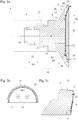
- the Figures 1 , 2nd and 3a show an arrangement 25 of a grinding tool 1 for grinding an engine block and an HSK receptacle 23.
- the grinding tool 1 comprises a base body 2, which has a central coupling area 3 for connecting the base body 2 to a rotary drive 4 of a grinding machine 5 (in FIG Figure 3a indicated by dashed lines), wherein the base body 2 is essentially rotationally symmetrical with respect to an axis of rotation 6.
- the central coupling area 3 is designed such that the grinding tool 1 can be connected to an HSK receptacle 23.
- the grinding tool 1 further comprises an abrasive coating 7, which extends at least over an outer annular zone 8 of the base body 2, at least one feed 9 for a cooling fluid 10, and an essentially circular cover plate 11, which is essentially normal to the axis of rotation 6 and with the formation of a Axial gap 12 is arranged on the base body 2, the axial gap 12 being in fluid communication with the at least one feed line 9 and the abrasive coating 7, so that a cooling fluid 10 supplied via the at least one feed line 9 is conducted via the axial gap 12 to the abrasive coating 7 can (compare Figure 3a ).
- the circular ring zone 8 of the base body 2 is oriented essentially normal to the axis of rotation 6.
- first channels 15 are arranged for the targeted conduction of the cooling fluid 10 from the at least one feed 9 to the abrasive coating 7.
- first channels 15 on a surface 14 of the cover plate 11 facing the base body 2 for the targeted routing of the cooling fluid 10 from the at least one feed 9 to the abrasive coating 7.
- first channels 15 for the targeted conduction of the cooling fluid 10 from the at least one on both the surface 13 of the base body 2 facing the cover plate 11 and the surface 14 facing the base body 2 Feed 9 to the abrasive coating 7 are arranged.
- the feed 9 for the cooling fluid 10 runs essentially parallel to the axis of rotation 6 or in the axial direction 29, and is designed as a bore in the base body 2. This feed 9 can continue in the HSK receptacle 23 in the form of an opening 33.
- the cover plate 11, the base body 2 and the HSK receptacle 23 are detachably connected to one another via connecting means 24 in the form of screws.
- the screws penetrate recesses 30 in the cover plate 11 and recesses 31 in the base body 2 and are mounted in bores 32 in the HSK receptacle 23.
- the screws 24 can have an external thread and the bores 32 can have a corresponding internal thread.
- cover plate 11 is connected to the base body 2, and on the other hand the package of cover plate 11 and base body 2 is connected to the HSK receptacle 23.
- the surface 13 of the base body 2 facing the cover plate 11 and the surface 14 of the cover plate 11 facing the base body 2 make contact in regions, specifically at the points at which no first channels 15 are provided.
- the base body 2 and the cover plate 11 each have an inclined surface 17, 18 which adjoins the abrasive coating 7, the inclined surfaces 17, 18 making contact in some areas.
- Second channels 19 are arranged on the inclined surface 17 for the targeted conduction of the cooling fluid 10.
- second channels 19 can be arranged for the targeted conduction of the cooling fluid 10.
- third channels 20 are arranged for the targeted conduction of the cooling fluid 10, the third channels 20 being connected to the second channels 19.
- An annular channel 26 is arranged between the base body 2 and the cover plate 11 for the targeted conduction of the cooling fluid 10.
- a cooling fluid 10 supplied in the axial direction 29 is conducted radially via the first channels 15 in the direction of the outer edge 21 of the base body 2, reaches the annular channel 26, from there into the second channels 19 and finally into the third channels 20, which are arranged in the abrasive coating 7.
- the outer annular zone 8 of the base body 2 is shown in detail.
- the abrasive coating 7 arranged in this circular ring zone 8 on the base body 2 comprises diamonds, is galvanically connected to the base body 2, and has a thickness 22 of 0.1 mm to 1 mm, preferably approximately 0.3 mm.
- the abrasive coating is not only oriented substantially normal to the axis of rotation 6, but also encloses part of the outer edge 21 of the base body 2.
- the Figures 4a and 4b details of the cooling fluid distribution system can be found: Starting from the feed 9, the first channels 15 run outward in a substantially radial direction 16. The channels 15 are each at the same angular distance from one another.
- the first channels 15 open into the annular channel 26, and the annular channel 26 is formed by a cavity between a partial surface 27 arranged on the base body 2 and a partial surface 28 arranged on the cover plate 11 (see also Figure 5 ).
- the cooling fluid 10 reaches the second channels 19. These are offset from the first channels 15. More second channels 19 than first channels 15 are provided. The second channels 19 likewise run outward in the radial direction 16.
- the cooling fluid 10 passes from the second channels 19 into the third channels 20, which are connected to the second channels 19.
- the same number of third channels 20 as second channels 19 are provided.
- the third channels 20 run obliquely with respect to the radial direction 16 and widen towards the outer edge 21 of the base body 2.
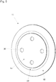
- the Figure 5 shows the cover plate 11 of the grinding tool 1 from behind.
- the surface 14 facing the base body 2, the partial surface 28, which, together with the partial surface 27 of the base body 2, delimits the annular channel 26 in the axial direction 29, and the inclined surface 18 can be seen.
- no channels for the targeted conduction of the cooling fluid 10 are arranged on the surface 14 and the inclined surface 18.
- 15 and 19 channels can be provided here in addition to or instead of the channels 15 and 19 provided on the base body.
Landscapes
- Engineering & Computer Science (AREA)
- Mechanical Engineering (AREA)
- Physics & Mathematics (AREA)
- Geometry (AREA)
- Polishing Bodies And Polishing Tools (AREA)
Priority Applications (1)
| Application Number | Priority Date | Filing Date | Title |
|---|---|---|---|
| PL19156235T PL3539720T3 (pl) | 2018-03-12 | 2019-02-08 | Narzędzie szlifierskie do szlifowania bloku silnika |
Applications Claiming Priority (1)
| Application Number | Priority Date | Filing Date | Title |
|---|---|---|---|
| ATA50211/2018A AT520966A1 (de) | 2018-03-12 | 2018-03-12 | Schleifwerkzeug zum Schleifen eines Motorblocks |
Publications (2)
| Publication Number | Publication Date |
|---|---|
| EP3539720A1 EP3539720A1 (de) | 2019-09-18 |
| EP3539720B1 true EP3539720B1 (de) | 2020-03-25 |
Family
ID=65365876
Family Applications (1)
| Application Number | Title | Priority Date | Filing Date |
|---|---|---|---|
| EP19156235.4A Active EP3539720B1 (de) | 2018-03-12 | 2019-02-08 | Schleifwerkzeug zum schleifen eines motorblocks |
Country Status (7)
| Country | Link |
|---|---|
| US (1) | US11969852B2 (pl) |
| EP (1) | EP3539720B1 (pl) |
| CN (1) | CN110253429B (pl) |
| AT (2) | AT520966A1 (pl) |
| ES (1) | ES2800431T3 (pl) |
| HU (1) | HUE049607T2 (pl) |
| PL (1) | PL3539720T3 (pl) |
Family Cites Families (28)
| Publication number | Priority date | Publication date | Assignee | Title |
|---|---|---|---|---|
| DE544374C (de) | 1932-02-17 | Wuelfel Eisenwerk | Luftgekuehlte Schleifscheibe fuer Trockenschliff | |
| US2410812A (en) * | 1945-06-30 | 1946-11-12 | Walter J Jacobsen | Support for abrasive disks |
| CH460572A (fr) | 1966-07-26 | 1968-07-31 | Juillerat Henri | Procédé de lubrification d'une meule et meule pour la mise en oeuvre du procédé |
| US3754359A (en) * | 1970-09-16 | 1973-08-28 | Spam D Avray | Abrasion tools |
| NL8006599A (nl) * | 1980-02-01 | 1981-09-01 | Disco Co Ltd | Slijpwiel voor vlakke platen alsmede werkwijze voor het vervaardigen daarvan. |
| SU901039A1 (ru) | 1980-06-09 | 1982-01-30 | Ульяновский политехнический институт | Устройство дл подачи смазочно-охлаждающей жидкости |
| US4854087A (en) * | 1987-02-28 | 1989-08-08 | Zahnradfabrik Friedrichshafen A.G. | Grinding disc |
| US5423717A (en) * | 1993-10-04 | 1995-06-13 | Ford Motor Company | Grinding wheel assembly |
| US5993297A (en) * | 1994-09-06 | 1999-11-30 | Makino Inc. | Superabrasive grinding wheel with integral coolant passage |
| FR2752762B1 (fr) * | 1996-08-29 | 1998-10-02 | Snecma | Meule de rectification avec arrosage incorpore |
| US6358133B1 (en) * | 1998-02-06 | 2002-03-19 | 3M Innovative Properties Company | Grinding wheel |
| SG119140A1 (en) | 2001-07-04 | 2006-02-28 | Disco Corp | Grinding wheel |
| RU2228832C1 (ru) | 2002-09-27 | 2004-05-20 | Институт технологических наук и проблем реструктурирования в промышленности | Абразивный инструмент для плоского шлифования |
| AT414105B (de) * | 2003-09-04 | 2006-09-15 | Schrottner Gerhard | Abdeckung zur mediumsführung bei schleifscheiben |
| AT502503B1 (de) | 2003-09-04 | 2007-04-15 | Schrottner Gerhard | Ringsystem zur mediumsführung bei schleifscheiben |
| EP1533078B1 (de) * | 2003-11-12 | 2008-04-30 | Erwin Junker Grinding Technology a.s. | Geteiltes Schleifwerkzeug |
| DE102005026648B4 (de) | 2005-06-09 | 2008-07-31 | Kennametal Inc. | Werkzeug und Verfahren zur Bearbeitung eines Werkstücks |
| US7384329B2 (en) * | 2006-05-23 | 2008-06-10 | Saint-Gobain Abrasives Technology Company | Coolant delivery system for grinding tools |
| AT505124B1 (de) | 2007-04-20 | 2010-02-15 | Swarovski Tyrolit Schleif | Schleifscheibe |
| JP2009208215A (ja) | 2008-03-06 | 2009-09-17 | Jtekt Corp | 溝入回転砥石及び研削盤 |
| DE102008025120B3 (de) * | 2008-05-26 | 2009-03-19 | Erwin Junker Maschinenfabrik Gmbh | Geteilte Schleifscheibe |
| JP5550940B2 (ja) | 2010-02-23 | 2014-07-16 | 株式会社ディスコ | 搬送機構 |
| JP5632215B2 (ja) | 2010-06-28 | 2014-11-26 | 株式会社ディスコ | 研削加工ツール |
| CN103249528B (zh) * | 2010-12-06 | 2014-11-12 | 小松Ntc株式会社 | 磨削砂轮 |
| KR20140121416A (ko) * | 2012-01-17 | 2014-10-15 | 구일린 챔피온 유니온 다이아몬드 컴퍼니 리미티드 | 실형방지 고효율 절삭 그라인더 |
| AT515475B1 (de) * | 2014-02-28 | 2016-04-15 | Swarovski Tyrolit Schleif | Herstellung einer Topfscheibe |
| MX369370B (es) * | 2015-04-08 | 2019-11-06 | Decatur Diamond Llc | Fresa con conductos lubricacion. |
| DE102016217344A1 (de) * | 2016-09-12 | 2018-03-15 | Deckel Maho Pfronten Gmbh | Kühlmittelzufuhreinrichtung und schleifwerkzeug mit einer kühlmittelzufuhreinrichtung für eine werkzeugmaschine |
-
2018
- 2018-03-12 AT ATA50211/2018A patent/AT520966A1/de active IP Right Grant
- 2018-03-12 AT ATGM8030/2022U patent/AT17877U1/de unknown
-
2019
- 2019-02-08 EP EP19156235.4A patent/EP3539720B1/de active Active
- 2019-02-08 ES ES19156235T patent/ES2800431T3/es active Active
- 2019-02-08 PL PL19156235T patent/PL3539720T3/pl unknown
- 2019-02-08 HU HUE19156235A patent/HUE049607T2/hu unknown
- 2019-02-13 US US16/274,489 patent/US11969852B2/en active Active
- 2019-03-12 CN CN201910182219.0A patent/CN110253429B/zh active Active
Non-Patent Citations (1)
| Title |
|---|
| None * |
Also Published As
| Publication number | Publication date |
|---|---|
| HUE049607T2 (hu) | 2020-09-28 |
| CN110253429B (zh) | 2021-10-15 |
| US20190275631A1 (en) | 2019-09-12 |
| ES2800431T3 (es) | 2020-12-30 |
| PL3539720T3 (pl) | 2020-09-07 |
| EP3539720A1 (de) | 2019-09-18 |
| CN110253429A (zh) | 2019-09-20 |
| AT520966A1 (de) | 2019-09-15 |
| AT17877U1 (de) | 2023-06-15 |
| US11969852B2 (en) | 2024-04-30 |
Similar Documents
| Publication | Publication Date | Title |
|---|---|---|
| EP2999566B1 (de) | Rotierendes werkzeug mit einer internen kühl- und/oder schmiermittelzuführung | |
| EP2550126B1 (de) | Hochleistungsreibahle mit kühlmittelkanälen | |
| EP2509745B1 (de) | Bausatz zum nachrüsten einer elektrodenschleifvorrichtung und elektrodenschleifvorrichtung | |
| DE10159431A1 (de) | Werkzeug für Feinstbearbeitung von Oberflächen | |
| DE10322360A1 (de) | Vorrichtung zum Feinbearbeiten von ebenen Flächen | |
| EP1533078B1 (de) | Geteiltes Schleifwerkzeug | |
| DE102016218103B3 (de) | Vorrichtung zur Kühlschmierstoff-Versorgung einer Werkzeugscheibe | |
| EP1834731B1 (de) | Verfahren zum Schleifen von Zerspanungswerkzeugen | |
| EP3826807B1 (de) | Trenn-, schleif- und polierscheibe, trennvorrichtung und verfahren zur bearbeitung von werkstücken | |
| DE10251922B4 (de) | Proben-Fräsmaschine | |
| EP3539720B1 (de) | Schleifwerkzeug zum schleifen eines motorblocks | |
| DE3108996A1 (de) | Vorrichtung zur bearbeitung von zylinderflaechen fuer spanabhebende werkzeugmaschinen | |
| DE102006014972B4 (de) | Kombiniertes Bearbeitungsverfahren und Bearbeitungseinrichtung | |
| CH661238A5 (de) | Schleiforgan zum schleifen von ventilsitzen in motoren sowie ein werkzeug mit dem schleiforgan. | |
| EP3496896A1 (de) | Werkzeugaufnahme | |
| DE102017102883A1 (de) | Verfahren und Werkzeug zum Entfernen einer Beschichtung von einem Substrat | |
| DE602004006149T2 (de) | Schleifgerät, dessen Anwendung zum Schleifen von zylindrischen Gegenständen , Vorrichtung und Verfahren zum Schleifen von zylindrischen Gegenständen | |
| DE102009044857A1 (de) | Anordnung zum Schleifen von Elektroden und Schleifscheibe | |
| DE19643192A1 (de) | Verfahren zum Bearbeiten von rotationssymmetrischen Werkstückflächen sowie Werkzeug zur Durchführung eines solchen Verfahrens | |
| WO2006002862A1 (de) | Werkzeug und vorrichtung zur bearbeitung von werkstücken | |
| DE102007037791A1 (de) | Kombiniertes Präzisionshartdrehen und Trockenschleifen | |
| DE202007016019U1 (de) | Werkzeug zur spanabhebenden Feinbearbeitung von Werkstücken | |
| EP3787835B1 (de) | Kombinierte schleif- und bürstenvorrichtung | |
| DE102015219786A1 (de) | Hartbearbeitungseinrichtung und Verfahren zur Hartbearbeitung eines Werkstoffs unter Einsatz einer solchen Hartbearbeitungseinrichtung | |
| DE29708235U1 (de) | Schleifkörper |
Legal Events
| Date | Code | Title | Description |
|---|---|---|---|
| PUAI | Public reference made under article 153(3) epc to a published international application that has entered the european phase |
Free format text: ORIGINAL CODE: 0009012 |
|
| STAA | Information on the status of an ep patent application or granted ep patent |
Free format text: STATUS: THE APPLICATION HAS BEEN PUBLISHED |
|
| AK | Designated contracting states |
Kind code of ref document: A1 Designated state(s): AL AT BE BG CH CY CZ DE DK EE ES FI FR GB GR HR HU IE IS IT LI LT LU LV MC MK MT NL NO PL PT RO RS SE SI SK SM TR |
|
| AX | Request for extension of the european patent |
Extension state: BA ME |
|
| STAA | Information on the status of an ep patent application or granted ep patent |
Free format text: STATUS: REQUEST FOR EXAMINATION WAS MADE |
|
| 17P | Request for examination filed |
Effective date: 20190925 |
|
| RBV | Designated contracting states (corrected) |
Designated state(s): AL AT BE BG CH CY CZ DE DK EE ES FI FR GB GR HR HU IE IS IT LI LT LU LV MC MK MT NL NO PL PT RO RS SE SI SK SM TR |
|
| GRAP | Despatch of communication of intention to grant a patent |
Free format text: ORIGINAL CODE: EPIDOSNIGR1 |
|
| STAA | Information on the status of an ep patent application or granted ep patent |
Free format text: STATUS: GRANT OF PATENT IS INTENDED |
|
| RIC1 | Information provided on ipc code assigned before grant |
Ipc: B24D 7/10 20060101ALI20191118BHEP Ipc: B24B 55/02 20060101AFI20191118BHEP Ipc: B24D 5/10 20060101ALI20191118BHEP |
|
| INTG | Intention to grant announced |
Effective date: 20191206 |
|
| GRAS | Grant fee paid |
Free format text: ORIGINAL CODE: EPIDOSNIGR3 |
|
| GRAA | (expected) grant |
Free format text: ORIGINAL CODE: 0009210 |
|
| STAA | Information on the status of an ep patent application or granted ep patent |
Free format text: STATUS: THE PATENT HAS BEEN GRANTED |
|
| AK | Designated contracting states |
Kind code of ref document: B1 Designated state(s): AL AT BE BG CH CY CZ DE DK EE ES FI FR GB GR HR HU IE IS IT LI LT LU LV MC MK MT NL NO PL PT RO RS SE SI SK SM TR |
|
| REG | Reference to a national code |
Ref country code: GB Ref legal event code: FG4D Free format text: NOT ENGLISH |
|
| REG | Reference to a national code |
Ref country code: AT Ref legal event code: REF Ref document number: 1248028 Country of ref document: AT Kind code of ref document: T Effective date: 20200415 Ref country code: IE Ref legal event code: FG4D Free format text: LANGUAGE OF EP DOCUMENT: GERMAN |
|
| REG | Reference to a national code |
Ref country code: DE Ref legal event code: R096 Ref document number: 502019000015 Country of ref document: DE |
|
| REG | Reference to a national code |
Ref country code: SE Ref legal event code: TRGR |
|
| PG25 | Lapsed in a contracting state [announced via postgrant information from national office to epo] |
Ref country code: RS Free format text: LAPSE BECAUSE OF FAILURE TO SUBMIT A TRANSLATION OF THE DESCRIPTION OR TO PAY THE FEE WITHIN THE PRESCRIBED TIME-LIMIT Effective date: 20200325 Ref country code: FI Free format text: LAPSE BECAUSE OF FAILURE TO SUBMIT A TRANSLATION OF THE DESCRIPTION OR TO PAY THE FEE WITHIN THE PRESCRIBED TIME-LIMIT Effective date: 20200325 Ref country code: NO Free format text: LAPSE BECAUSE OF FAILURE TO SUBMIT A TRANSLATION OF THE DESCRIPTION OR TO PAY THE FEE WITHIN THE PRESCRIBED TIME-LIMIT Effective date: 20200625 |
|
| PG25 | Lapsed in a contracting state [announced via postgrant information from national office to epo] |
Ref country code: HR Free format text: LAPSE BECAUSE OF FAILURE TO SUBMIT A TRANSLATION OF THE DESCRIPTION OR TO PAY THE FEE WITHIN THE PRESCRIBED TIME-LIMIT Effective date: 20200325 Ref country code: GR Free format text: LAPSE BECAUSE OF FAILURE TO SUBMIT A TRANSLATION OF THE DESCRIPTION OR TO PAY THE FEE WITHIN THE PRESCRIBED TIME-LIMIT Effective date: 20200626 Ref country code: BG Free format text: LAPSE BECAUSE OF FAILURE TO SUBMIT A TRANSLATION OF THE DESCRIPTION OR TO PAY THE FEE WITHIN THE PRESCRIBED TIME-LIMIT Effective date: 20200625 Ref country code: LV Free format text: LAPSE BECAUSE OF FAILURE TO SUBMIT A TRANSLATION OF THE DESCRIPTION OR TO PAY THE FEE WITHIN THE PRESCRIBED TIME-LIMIT Effective date: 20200325 |
|
| REG | Reference to a national code |
Ref country code: NL Ref legal event code: MP Effective date: 20200325 |
|
| REG | Reference to a national code |
Ref country code: LT Ref legal event code: MG4D |
|
| REG | Reference to a national code |
Ref country code: HU Ref legal event code: AG4A Ref document number: E049607 Country of ref document: HU |
|
| PG25 | Lapsed in a contracting state [announced via postgrant information from national office to epo] |
Ref country code: NL Free format text: LAPSE BECAUSE OF FAILURE TO SUBMIT A TRANSLATION OF THE DESCRIPTION OR TO PAY THE FEE WITHIN THE PRESCRIBED TIME-LIMIT Effective date: 20200325 |
|
| PG25 | Lapsed in a contracting state [announced via postgrant information from national office to epo] |
Ref country code: IS Free format text: LAPSE BECAUSE OF FAILURE TO SUBMIT A TRANSLATION OF THE DESCRIPTION OR TO PAY THE FEE WITHIN THE PRESCRIBED TIME-LIMIT Effective date: 20200725 Ref country code: SK Free format text: LAPSE BECAUSE OF FAILURE TO SUBMIT A TRANSLATION OF THE DESCRIPTION OR TO PAY THE FEE WITHIN THE PRESCRIBED TIME-LIMIT Effective date: 20200325 Ref country code: EE Free format text: LAPSE BECAUSE OF FAILURE TO SUBMIT A TRANSLATION OF THE DESCRIPTION OR TO PAY THE FEE WITHIN THE PRESCRIBED TIME-LIMIT Effective date: 20200325 Ref country code: SM Free format text: LAPSE BECAUSE OF FAILURE TO SUBMIT A TRANSLATION OF THE DESCRIPTION OR TO PAY THE FEE WITHIN THE PRESCRIBED TIME-LIMIT Effective date: 20200325 Ref country code: RO Free format text: LAPSE BECAUSE OF FAILURE TO SUBMIT A TRANSLATION OF THE DESCRIPTION OR TO PAY THE FEE WITHIN THE PRESCRIBED TIME-LIMIT Effective date: 20200325 Ref country code: PT Free format text: LAPSE BECAUSE OF FAILURE TO SUBMIT A TRANSLATION OF THE DESCRIPTION OR TO PAY THE FEE WITHIN THE PRESCRIBED TIME-LIMIT Effective date: 20200818 Ref country code: LT Free format text: LAPSE BECAUSE OF FAILURE TO SUBMIT A TRANSLATION OF THE DESCRIPTION OR TO PAY THE FEE WITHIN THE PRESCRIBED TIME-LIMIT Effective date: 20200325 |
|
| REG | Reference to a national code |
Ref country code: DE Ref legal event code: R097 Ref document number: 502019000015 Country of ref document: DE |
|
| PG25 | Lapsed in a contracting state [announced via postgrant information from national office to epo] |
Ref country code: DK Free format text: LAPSE BECAUSE OF FAILURE TO SUBMIT A TRANSLATION OF THE DESCRIPTION OR TO PAY THE FEE WITHIN THE PRESCRIBED TIME-LIMIT Effective date: 20200325 |
|
| PLBE | No opposition filed within time limit |
Free format text: ORIGINAL CODE: 0009261 |
|
| STAA | Information on the status of an ep patent application or granted ep patent |
Free format text: STATUS: NO OPPOSITION FILED WITHIN TIME LIMIT |
|
| 26N | No opposition filed |
Effective date: 20210112 |
|
| PG25 | Lapsed in a contracting state [announced via postgrant information from national office to epo] |
Ref country code: MC Free format text: LAPSE BECAUSE OF FAILURE TO SUBMIT A TRANSLATION OF THE DESCRIPTION OR TO PAY THE FEE WITHIN THE PRESCRIBED TIME-LIMIT Effective date: 20200325 |
|
| REG | Reference to a national code |
Ref country code: BE Ref legal event code: MM Effective date: 20210228 |
|
| PG25 | Lapsed in a contracting state [announced via postgrant information from national office to epo] |
Ref country code: LU Free format text: LAPSE BECAUSE OF NON-PAYMENT OF DUE FEES Effective date: 20210208 |
|
| PG25 | Lapsed in a contracting state [announced via postgrant information from national office to epo] |
Ref country code: IE Free format text: LAPSE BECAUSE OF NON-PAYMENT OF DUE FEES Effective date: 20210208 |
|
| PG25 | Lapsed in a contracting state [announced via postgrant information from national office to epo] |
Ref country code: BE Free format text: LAPSE BECAUSE OF NON-PAYMENT OF DUE FEES Effective date: 20210228 |
|
| REG | Reference to a national code |
Ref country code: CH Ref legal event code: PL |
|
| PG25 | Lapsed in a contracting state [announced via postgrant information from national office to epo] |
Ref country code: LI Free format text: LAPSE BECAUSE OF NON-PAYMENT OF DUE FEES Effective date: 20220228 Ref country code: CH Free format text: LAPSE BECAUSE OF NON-PAYMENT OF DUE FEES Effective date: 20220228 |
|
| PG25 | Lapsed in a contracting state [announced via postgrant information from national office to epo] |
Ref country code: CY Free format text: LAPSE BECAUSE OF FAILURE TO SUBMIT A TRANSLATION OF THE DESCRIPTION OR TO PAY THE FEE WITHIN THE PRESCRIBED TIME-LIMIT Effective date: 20200325 |
|
| PG25 | Lapsed in a contracting state [announced via postgrant information from national office to epo] |
Ref country code: SI Free format text: LAPSE BECAUSE OF FAILURE TO SUBMIT A TRANSLATION OF THE DESCRIPTION OR TO PAY THE FEE WITHIN THE PRESCRIBED TIME-LIMIT Effective date: 20200325 |
|
| PG25 | Lapsed in a contracting state [announced via postgrant information from national office to epo] |
Ref country code: MK Free format text: LAPSE BECAUSE OF FAILURE TO SUBMIT A TRANSLATION OF THE DESCRIPTION OR TO PAY THE FEE WITHIN THE PRESCRIBED TIME-LIMIT Effective date: 20200325 |
|
| PG25 | Lapsed in a contracting state [announced via postgrant information from national office to epo] |
Ref country code: TR Free format text: LAPSE BECAUSE OF FAILURE TO SUBMIT A TRANSLATION OF THE DESCRIPTION OR TO PAY THE FEE WITHIN THE PRESCRIBED TIME-LIMIT Effective date: 20200325 |
|
| PG25 | Lapsed in a contracting state [announced via postgrant information from national office to epo] |
Ref country code: MT Free format text: LAPSE BECAUSE OF FAILURE TO SUBMIT A TRANSLATION OF THE DESCRIPTION OR TO PAY THE FEE WITHIN THE PRESCRIBED TIME-LIMIT Effective date: 20200325 |
|
| PGFP | Annual fee paid to national office [announced via postgrant information from national office to epo] |
Ref country code: HU Payment date: 20250121 Year of fee payment: 7 |
|
| PGFP | Annual fee paid to national office [announced via postgrant information from national office to epo] |
Ref country code: ES Payment date: 20250311 Year of fee payment: 7 |
|
| PGFP | Annual fee paid to national office [announced via postgrant information from national office to epo] |
Ref country code: SE Payment date: 20250217 Year of fee payment: 7 |
|
| PGFP | Annual fee paid to national office [announced via postgrant information from national office to epo] |
Ref country code: AT Payment date: 20250224 Year of fee payment: 7 |
|
| PGFP | Annual fee paid to national office [announced via postgrant information from national office to epo] |
Ref country code: FR Payment date: 20250217 Year of fee payment: 7 Ref country code: PL Payment date: 20250110 Year of fee payment: 7 Ref country code: CZ Payment date: 20250110 Year of fee payment: 7 |
|
| PGFP | Annual fee paid to national office [announced via postgrant information from national office to epo] |
Ref country code: IT Payment date: 20250123 Year of fee payment: 7 |
|
| PGFP | Annual fee paid to national office [announced via postgrant information from national office to epo] |
Ref country code: GB Payment date: 20260223 Year of fee payment: 8 |
|
| PGFP | Annual fee paid to national office [announced via postgrant information from national office to epo] |
Ref country code: DE Payment date: 20260220 Year of fee payment: 8 |