EP3532285B1 - Verfahren zum herstellen einer verbundscheibe für ein kraftfahrzeug - Google Patents
Verfahren zum herstellen einer verbundscheibe für ein kraftfahrzeug Download PDFInfo
- Publication number
- EP3532285B1 EP3532285B1 EP17783400.9A EP17783400A EP3532285B1 EP 3532285 B1 EP3532285 B1 EP 3532285B1 EP 17783400 A EP17783400 A EP 17783400A EP 3532285 B1 EP3532285 B1 EP 3532285B1
- Authority
- EP
- European Patent Office
- Prior art keywords
- plastic film
- pane
- light
- emitting diode
- led
- Prior art date
- Legal status (The legal status is an assumption and is not a legal conclusion. Google has not performed a legal analysis and makes no representation as to the accuracy of the status listed.)
- Active
Links
Images
Classifications
-
- B—PERFORMING OPERATIONS; TRANSPORTING
- B32—LAYERED PRODUCTS
- B32B—LAYERED PRODUCTS, i.e. PRODUCTS BUILT-UP OF STRATA OF FLAT OR NON-FLAT, e.g. CELLULAR OR HONEYCOMB, FORM
- B32B37/00—Methods or apparatus for laminating, e.g. by curing or by ultrasonic bonding
- B32B37/06—Methods or apparatus for laminating, e.g. by curing or by ultrasonic bonding characterised by the heating method
-
- B—PERFORMING OPERATIONS; TRANSPORTING
- B32—LAYERED PRODUCTS
- B32B—LAYERED PRODUCTS, i.e. PRODUCTS BUILT-UP OF STRATA OF FLAT OR NON-FLAT, e.g. CELLULAR OR HONEYCOMB, FORM
- B32B17/00—Layered products essentially comprising sheet glass, or glass, slag, or like fibres
- B32B17/06—Layered products essentially comprising sheet glass, or glass, slag, or like fibres comprising glass as the main or only constituent of a layer, next to another layer of a specific material
- B32B17/10—Layered products essentially comprising sheet glass, or glass, slag, or like fibres comprising glass as the main or only constituent of a layer, next to another layer of a specific material of synthetic resin
- B32B17/10005—Layered products essentially comprising sheet glass, or glass, slag, or like fibres comprising glass as the main or only constituent of a layer, next to another layer of a specific material of synthetic resin laminated safety glass or glazing
- B32B17/10009—Layered products essentially comprising sheet glass, or glass, slag, or like fibres comprising glass as the main or only constituent of a layer, next to another layer of a specific material of synthetic resin laminated safety glass or glazing characterized by the number, the constitution or treatment of glass sheets
- B32B17/10036—Layered products essentially comprising sheet glass, or glass, slag, or like fibres comprising glass as the main or only constituent of a layer, next to another layer of a specific material of synthetic resin laminated safety glass or glazing characterized by the number, the constitution or treatment of glass sheets comprising two outer glass sheets
-
- B—PERFORMING OPERATIONS; TRANSPORTING
- B32—LAYERED PRODUCTS
- B32B—LAYERED PRODUCTS, i.e. PRODUCTS BUILT-UP OF STRATA OF FLAT OR NON-FLAT, e.g. CELLULAR OR HONEYCOMB, FORM
- B32B17/00—Layered products essentially comprising sheet glass, or glass, slag, or like fibres
- B32B17/06—Layered products essentially comprising sheet glass, or glass, slag, or like fibres comprising glass as the main or only constituent of a layer, next to another layer of a specific material
- B32B17/10—Layered products essentially comprising sheet glass, or glass, slag, or like fibres comprising glass as the main or only constituent of a layer, next to another layer of a specific material of synthetic resin
- B32B17/10005—Layered products essentially comprising sheet glass, or glass, slag, or like fibres comprising glass as the main or only constituent of a layer, next to another layer of a specific material of synthetic resin laminated safety glass or glazing
- B32B17/10165—Functional features of the laminated safety glass or glazing
- B32B17/10541—Functional features of the laminated safety glass or glazing comprising a light source or a light guide
-
- B—PERFORMING OPERATIONS; TRANSPORTING
- B32—LAYERED PRODUCTS
- B32B—LAYERED PRODUCTS, i.e. PRODUCTS BUILT-UP OF STRATA OF FLAT OR NON-FLAT, e.g. CELLULAR OR HONEYCOMB, FORM
- B32B17/00—Layered products essentially comprising sheet glass, or glass, slag, or like fibres
- B32B17/06—Layered products essentially comprising sheet glass, or glass, slag, or like fibres comprising glass as the main or only constituent of a layer, next to another layer of a specific material
- B32B17/10—Layered products essentially comprising sheet glass, or glass, slag, or like fibres comprising glass as the main or only constituent of a layer, next to another layer of a specific material of synthetic resin
- B32B17/10005—Layered products essentially comprising sheet glass, or glass, slag, or like fibres comprising glass as the main or only constituent of a layer, next to another layer of a specific material of synthetic resin laminated safety glass or glazing
- B32B17/1055—Layered products essentially comprising sheet glass, or glass, slag, or like fibres comprising glass as the main or only constituent of a layer, next to another layer of a specific material of synthetic resin laminated safety glass or glazing characterized by the resin layer, i.e. interlayer
-
- B—PERFORMING OPERATIONS; TRANSPORTING
- B32—LAYERED PRODUCTS
- B32B—LAYERED PRODUCTS, i.e. PRODUCTS BUILT-UP OF STRATA OF FLAT OR NON-FLAT, e.g. CELLULAR OR HONEYCOMB, FORM
- B32B17/00—Layered products essentially comprising sheet glass, or glass, slag, or like fibres
- B32B17/06—Layered products essentially comprising sheet glass, or glass, slag, or like fibres comprising glass as the main or only constituent of a layer, next to another layer of a specific material
- B32B17/10—Layered products essentially comprising sheet glass, or glass, slag, or like fibres comprising glass as the main or only constituent of a layer, next to another layer of a specific material of synthetic resin
- B32B17/10005—Layered products essentially comprising sheet glass, or glass, slag, or like fibres comprising glass as the main or only constituent of a layer, next to another layer of a specific material of synthetic resin laminated safety glass or glazing
- B32B17/1055—Layered products essentially comprising sheet glass, or glass, slag, or like fibres comprising glass as the main or only constituent of a layer, next to another layer of a specific material of synthetic resin laminated safety glass or glazing characterized by the resin layer, i.e. interlayer
- B32B17/10761—Layered products essentially comprising sheet glass, or glass, slag, or like fibres comprising glass as the main or only constituent of a layer, next to another layer of a specific material of synthetic resin laminated safety glass or glazing characterized by the resin layer, i.e. interlayer containing vinyl acetal
-
- B—PERFORMING OPERATIONS; TRANSPORTING
- B32—LAYERED PRODUCTS
- B32B—LAYERED PRODUCTS, i.e. PRODUCTS BUILT-UP OF STRATA OF FLAT OR NON-FLAT, e.g. CELLULAR OR HONEYCOMB, FORM
- B32B17/00—Layered products essentially comprising sheet glass, or glass, slag, or like fibres
- B32B17/06—Layered products essentially comprising sheet glass, or glass, slag, or like fibres comprising glass as the main or only constituent of a layer, next to another layer of a specific material
- B32B17/10—Layered products essentially comprising sheet glass, or glass, slag, or like fibres comprising glass as the main or only constituent of a layer, next to another layer of a specific material of synthetic resin
- B32B17/10005—Layered products essentially comprising sheet glass, or glass, slag, or like fibres comprising glass as the main or only constituent of a layer, next to another layer of a specific material of synthetic resin laminated safety glass or glazing
- B32B17/10807—Making laminated safety glass or glazing; Apparatus therefor
- B32B17/10816—Making laminated safety glass or glazing; Apparatus therefor by pressing
- B32B17/10871—Making laminated safety glass or glazing; Apparatus therefor by pressing in combination with particular heat treatment
-
- B—PERFORMING OPERATIONS; TRANSPORTING
- B32—LAYERED PRODUCTS
- B32B—LAYERED PRODUCTS, i.e. PRODUCTS BUILT-UP OF STRATA OF FLAT OR NON-FLAT, e.g. CELLULAR OR HONEYCOMB, FORM
- B32B37/00—Methods or apparatus for laminating, e.g. by curing or by ultrasonic bonding
- B32B37/04—Methods or apparatus for laminating, e.g. by curing or by ultrasonic bonding characterised by the partial melting of at least one layer
-
- B—PERFORMING OPERATIONS; TRANSPORTING
- B29—WORKING OF PLASTICS; WORKING OF SUBSTANCES IN A PLASTIC STATE IN GENERAL
- B29L—INDEXING SCHEME ASSOCIATED WITH SUBCLASS B29C, RELATING TO PARTICULAR ARTICLES
- B29L2031/00—Other particular articles
- B29L2031/30—Vehicles, e.g. ships or aircraft, or body parts thereof
- B29L2031/3052—Windscreens
-
- B—PERFORMING OPERATIONS; TRANSPORTING
- B32—LAYERED PRODUCTS
- B32B—LAYERED PRODUCTS, i.e. PRODUCTS BUILT-UP OF STRATA OF FLAT OR NON-FLAT, e.g. CELLULAR OR HONEYCOMB, FORM
- B32B2605/00—Vehicles
- B32B2605/006—Transparent parts other than made from inorganic glass, e.g. polycarbonate glazings
-
- B—PERFORMING OPERATIONS; TRANSPORTING
- B60—VEHICLES IN GENERAL
- B60K—ARRANGEMENT OR MOUNTING OF PROPULSION UNITS OR OF TRANSMISSIONS IN VEHICLES; ARRANGEMENT OR MOUNTING OF PLURAL DIVERSE PRIME-MOVERS IN VEHICLES; AUXILIARY DRIVES FOR VEHICLES; INSTRUMENTATION OR DASHBOARDS FOR VEHICLES; ARRANGEMENTS IN CONNECTION WITH COOLING, AIR INTAKE, GAS EXHAUST OR FUEL SUPPLY OF PROPULSION UNITS IN VEHICLES
- B60K2360/00—Indexing scheme associated with groups B60K35/00 or B60K37/00 relating to details of instruments or dashboards
- B60K2360/77—Instrument locations other than the dashboard
- B60K2360/785—Instrument locations other than the dashboard on or in relation to the windshield or windows
-
- B—PERFORMING OPERATIONS; TRANSPORTING
- B60—VEHICLES IN GENERAL
- B60K—ARRANGEMENT OR MOUNTING OF PROPULSION UNITS OR OF TRANSMISSIONS IN VEHICLES; ARRANGEMENT OR MOUNTING OF PLURAL DIVERSE PRIME-MOVERS IN VEHICLES; AUXILIARY DRIVES FOR VEHICLES; INSTRUMENTATION OR DASHBOARDS FOR VEHICLES; ARRANGEMENTS IN CONNECTION WITH COOLING, AIR INTAKE, GAS EXHAUST OR FUEL SUPPLY OF PROPULSION UNITS IN VEHICLES
- B60K35/00—Instruments specially adapted for vehicles; Arrangement of instruments in or on vehicles
- B60K35/20—Output arrangements, i.e. from vehicle to user, associated with vehicle functions or specially adapted therefor
- B60K35/21—Output arrangements, i.e. from vehicle to user, associated with vehicle functions or specially adapted therefor using visual output, e.g. blinking lights or matrix displays
- B60K35/23—Head-up displays [HUD]
-
- B—PERFORMING OPERATIONS; TRANSPORTING
- B60—VEHICLES IN GENERAL
- B60K—ARRANGEMENT OR MOUNTING OF PROPULSION UNITS OR OF TRANSMISSIONS IN VEHICLES; ARRANGEMENT OR MOUNTING OF PLURAL DIVERSE PRIME-MOVERS IN VEHICLES; AUXILIARY DRIVES FOR VEHICLES; INSTRUMENTATION OR DASHBOARDS FOR VEHICLES; ARRANGEMENTS IN CONNECTION WITH COOLING, AIR INTAKE, GAS EXHAUST OR FUEL SUPPLY OF PROPULSION UNITS IN VEHICLES
- B60K35/00—Instruments specially adapted for vehicles; Arrangement of instruments in or on vehicles
- B60K35/60—Instruments characterised by their location or relative disposition in or on vehicles
-
- G—PHYSICS
- G02—OPTICS
- G02B—OPTICAL ELEMENTS, SYSTEMS OR APPARATUS
- G02B27/00—Optical systems or apparatus not provided for by any of the groups G02B1/00 - G02B26/00, G02B30/00
- G02B27/01—Head-up displays
- G02B2027/0192—Supplementary details
- G02B2027/0196—Supplementary details having transparent supporting structure for display mounting, e.g. to a window or a windshield
Definitions
- the invention relates to a method for producing a composite pane for a motor vehicle.
- the CH 698260 B1 discloses, for example, a built-in element with a flexible polymer film coated translucently by means of conductive oxide or metal, such as PET, as well as with electronic components connected by electrically conductive adhesive dots, the electrically conductive adhesive dots between the conductive coating and the components against pressure by electrically non-conductive reinforcing adhesive dots -, tensile or shear forces are protected.
- the EP 2100722 A2 a light sensor which is laminated into a windshield, that is to say is arranged between the outer pane and the inner pane of the windshield, which are connected to one another by means of a thermoplastic intermediate layer.
- the light sensor is designed in the form of flip-chip photodiodes on a circuit board.
- the embedding of light-emitting diodes in a soft thermoplastic intermediate layer during the calendering of a composite pane by means of a pair of rollers is from the WO 2007/057454 A1 known.
- a disadvantage of this procedure is the possibility of damage to the light-emitting diodes, in particular sensitive electrical connections of the light-emitting diodes, during calendering by mechanical forces, in particular shear forces.
- the temperature during calendering must be matched to the embedding of the light-emitting diodes, which may deviate from an optimal temperature for the calendering process.
- the invention is therefore based on the object of specifying an improved method for producing the composite pane which enables the use of thicker electronic components without generating stresses in the composite pane.
- the object of the present invention is achieved according to the invention by a method for producing a composite pane for a motor vehicle according to the independent claim.
- the present invention shows a method for producing a composite window for a motor vehicle.
- the method comprises providing a first pane and a second pane, arranging a plastic film between the first pane and the second pane, and arranging a light-emitting diode on a surface of the plastic film.
- the method further comprises heating the plastic film at least in the area of the light-emitting diode into a flowable state and inserting the light-emitting diode into the plastic film heated into the flowable state while displacing a predetermined volume of the plastic film.
- the plastic film is heated locally by the heat source exclusively in a section or part of the plastic film. There is thus no heating of the entire plastic film, as occurs when laminating, in particular calendering, the composite pane.
- the first pane and the second pane are laminated with an interposed plastic film.
- laminate in the sense of the invention relates to the connection of the two panes by the interposed plastic film, the plastic film being heated not locally but as a whole.
- the light emitting diode is inserted before the first one
- the pane and the second pane are connected to form a composite ("laminated") by means of a thermoplastic intermediate layer.
- the plastic film is locally heated to the flowable state in the area of the light-emitting diode.
- the light-emitting diode can then penetrate the plastic film while displacing a predetermined volume and create a recess in the plastic film. Due to the displacement of the predetermined volume of the plastic film in the heated state of the plastic film, it is advantageously made possible that, in contrast to pressing the light-emitting diode into the plastic film in the cold state, a total thickness of the light-emitting diode and the plastic film does not exceed a reliable thickness and thus the generation of Tension in the discs is avoided.
- a displaced volume of the plastic film can thus advantageously flow off in other directions and a thickness of the plastic film with inserted light-emitting diode essentially corresponds to a thickness of the plastic film without inserted light-emitting diode.
- thicker light-emitting diodes which, in contrast to very thin light-emitting diodes, are significantly more cost-effective to manufacture, can be used. Since the light-emitting diode is inserted into the plastic film before the laminated pane is laminated, the light-emitting diode is mechanically well protected. Damage to the light-emitting diode, in particular to sensitive electrical connections, can be reliably and safely avoided.
- the light-emitting diode can be positioned with high precision.
- the disadvantages of embedding light-emitting diodes during lamination, known in the prior art, can be avoided. Due to the only local introduction of heat into the plastic film, it is advantageously avoided that the plastic film adheres to the panes of the composite pane and there is air inclusions associated therewith before the composite pane is degassed. In particular, the plastic film is heated to the flowable state, at least in the area of the light-emitting diode, before the laminated pane is vented.
- the heat source heats the plastic film, at least in the area of the light-emitting diode, into the flowable state while emitting radiant heat and / or convection heat.
- a large number of different heat sources can thus be used to introduce the heat into the plastic film.
- the heat source is formed by a heating foil which is glued onto the outer surface of the first pane or the second pane. Providing the heating foil is an advantageous cost-effective solution and enables a uniform input of heat in the area of a definable area.
- the heating foil is exclusively glued to a part or section of the outer surface of the first pane or the second pane.
- the plastic film is heated to a temperature of 50 to 150 ° C., preferably from 80 to 150 ° C., the plastic film retaining its shape after cooling below a temperature of 50 ° C.
- the temperature range mentioned above advantageously corresponds to a glass transition temperature at which the plastic changes to a rubber-like to viscous state and is therefore flowable.
- the light-emitting diode is inserted into the plastic film, which has been heated to the flowable state, using a force that is essentially perpendicular to the plastic film.
- the light-emitting diode can thus be inserted into the plastic film in a precisely positioned manner.
- the predetermined volume of the plastic film is displaced essentially in the longitudinal direction of the plastic film when the light-emitting diode is inserted into the plastic film heated to the flowable state.
- the thickness of the plastic film is advantageously not increased even when a relatively thick light-emitting diode is inserted.
- the light-emitting diode when the light-emitting diode is inserted into the plastic film heated to the flowable state, up to 100%, preferably up to 95%, particularly preferably up to 90% of the volume of the plastic film in the thickness direction of the plastic film is displaced by the light-emitting diode becomes.
- the light-emitting diode is thus advantageously inserted into the plastic film, with only a minimal thickness of essentially 0%, 5% or 10% of the plastic film remaining.
- the plastic film contains polyvinyl butyral, ethylene vinyl acetate, polyacrylate, polymethyl methacrylate or polyurethane or consists of one or more of these materials.
- a suitable material of the plastic film can be selected for a corresponding application.
- the light-emitting diode is arranged on a printed circuit board, in particular comprising a film.
- the power supply of the light-emitting diode can thus be ensured and a desired positioning can be made possible depending on the structural requirements in the area of the laminated pane.
- the light-emitting diode has a thickness of up to 1 mm, preferably of up to 0.7 mm. Light-emitting diodes of this thickness can be produced significantly more cost-effectively than thinner light-emitting diodes and thus contribute to a cost reduction of the composite pane equipped with the light-emitting diode or diodes.
- a light emission side of the light-emitting diode is oriented towards the first pane or towards the second pane.
- the light-emitting diode can be aligned, for example, towards a passenger compartment or towards an outside of the motor vehicle. This results in a different purpose depending on the orientation of the light-emitting diode.
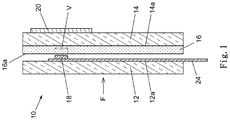
- the composite pane 10 for the motor vehicle has a first pane 12 and a second pane 14.
- a plastic film 16 is arranged between the first disk 12 and the second disk 14.
- a light-emitting diode 18 is arranged on a surface 16a of the plastic film 16.
- a heat source 20 is provided, which at least in the area of the light-emitting diode 18 rests or is arranged on an outer surface of the second pane 14.
- the heat source 20 can be spaced from the outer surface 14a of the second pane.
- the heat source 20 can be arranged, for example, on an outer surface 12a of the first pane 12 or arranged at a distance from the outer surface 12a of the first pane 12.
- the heat source 20 is formed by a heating foil.
- the heating film is glued to the outer surface 14 a of the second pane 14.
- another suitable heat source can be provided, which is designed, for example, to give off radiant heat and / or convection heat.
- the heating film heats the plastic film 16 locally, at least in the area of the light-emitting diode 18, into a flowable state.
- this flowable state of the plastic film 16 is the Light-emitting diode 18 can be inserted or pressed into the heated plastic film 16 while displacing a predetermined volume V of the plastic film 16 into the plastic film 16.
- the light-emitting diode 18 is inserted into the plastic film 16, which has been heated to the flowable state, preferably using a force F directed essentially perpendicularly to the plastic film 16. Alternatively, the force can also have a different direction.
- the plastic film is heated to a temperature of 50 to 150 ° C, preferably 80 to 150 ° C.
- the plastic film preferably retains its shape after cooling below a temperature of 50 ° C.
- the predetermined volume V of the plastic film 16 is displaced essentially in the longitudinal direction of the plastic film 16 when the light-emitting diode 18 is inserted into the plastic film 16 heated to the flowable state.
- a thickness of the plastic film 16 is maintained in an advantageous manner.
- up to 90% of the volume V of the plastic film 16 is displaced by the light-emitting diode 18 in the direction of the thickness of the plastic film 16.
- the plastic film 16 is preferably formed from polyvinyl butyral. Alternatively, the plastic film 16 can be formed from ethylene vinyl acetate, polyacrylate, polymethyl methacrylate or polyurethane, for example.
- the light-emitting diode 18 is arranged on a printed circuit board, in particular comprising a further film. Alternatively, the light-emitting diode 18 can be connected to an energy source, for example by a thin electrical cable. The number of LEDs used can be freely selected.
- a thickness of the light-emitting diode 18 is up to 1 mm, preferably up to 0.7 mm.
- a light emission side of the light-emitting diode 18 is preferably oriented towards the second pane 14. Alternatively, the light-emitting side of the light-emitting diode 18 can be oriented towards the first pane 12, for example.
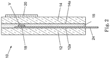
- Fig. 2 shows a side view of a composite pane for a motor vehicle after a light-emitting diode has been inserted into a plastic film according to a preferred embodiment of the invention.
- the plastic film has already been heated to the flowable state by the heating film and the light-emitting diode 18 has been inserted into the plastic film 16 heated to the flowable state, displacing the specified volume V of the plastic film 16.
- a distance between the first pane 12 and the second pane 14 of the composite pane is as in FIG Fig. 2 thus shown only minimally greater than a thickness of the light-emitting diode 18. This results because the plastic film 16 heated to the flowable state is displaced when the light-emitting diode 18 is inserted in the area of the light-emitting diode 18.
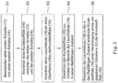
- FIG. 11 shows a flow chart of a method for producing the composite pane for the motor vehicle according to the preferred embodiment of the invention.
- the method comprises providing a first pane and a second pane, according to step S2 arranging a plastic film between the first pane and the second pane and according to step S3 arranging a light-emitting diode on a surface of the plastic film.
- the method further comprises, according to step S4, the heating of the plastic film at least in the area of the light-emitting diode into a flowable state and, according to step S5, the insertion of the light-emitting diode into the plastic film heated into the flowable state while displacing a predetermined volume of the plastic film, as well as the subsequent lamination of the first disc and the second disc with an interposed plastic film.
- the composite pane 10 of the present invention can be used not only in the area of motor vehicles, but also in the area of buildings in the context of building glazing.
Landscapes
- Physics & Mathematics (AREA)
- Thermal Sciences (AREA)
- Laminated Bodies (AREA)
- Joining Of Glass To Other Materials (AREA)
- Arrangements Of Lighting Devices For Vehicle Interiors, Mounting And Supporting Thereof, Circuits Therefore (AREA)
- Lining Or Joining Of Plastics Or The Like (AREA)
- Manufacture Of Motors, Generators (AREA)
Description
- Die Erfindung betrifft ein Verfahren zum Herstellen einer Verbundscheibe für ein Kraftfahrzeug.
- Herkömmlicherweise werden elektronische Komponenten zwischen jeweiligen Scheiben einer Verbundglasscheibe angeordnet, um je nach Einsatzzweck unterschiedliche Aufgaben zu erfüllen. Die
CH 698260 B1 - Ferner offenbart die
EP 2100722 A2 einen Lichtsensor, welcher in einer Windschutzscheibe einlaminiert ist, also zwischen der Außenscheibe und der Innenscheibe der Windschutzscheibe angeordnet ist, welche mittels einer thermoplastischen Zwischenschicht miteinander verbunden sind. So kann die Windschutzscheibe mit dem integrierten Lichtsensor kompakt bereitgestellt werden, eine nachträgliche Montage des Lichtsensors entfällt. Der Lichtsensor ist in Form von Flip-Chip-Fotodioden auf einer Leiterplatte ausgebildet.Ein Nachteil der vorstehend genannten Lösungen besteht jedoch darin, dass die jeweiligen Elektronikkomponenten derart benachbart zu der thermoplastischen Zwischenschicht angeordnet sind, dass diese an der Zwischenschicht anliegen und die Zwischenschicht somit eine Dicke der jeweiligen Elektronikkomponenten kompensiert. Deshalb ist es erforderlich, möglichst dünn ausgebildete Elektronikkomponenten zu verwenden, um zu gewährleisten, dass die Zwischenschicht die Dicke der Elektronikkomponenten ausgleichen kann. Bei Verwendung dickerer Elektronikkomponenten kann es daher in nachteilhafter Weise zu einem Glasbruch kommen, wenn die Zwischenschicht nicht in der Lage ist, die Dicke der Elektronikkomponenten auszugleichen und es somit zu Spannungen in den Scheiben kommt. - Das Einbetten von Leuchtdioden in eine weiche thermoplastische Zwischenschicht während des Kalandrierens einer Verbundscheibe durch ein Walzenpaar ist aus der
WO 2007/057454 A1 bekannt. Nachteilig bei dieser Vorgehensweise ist die Möglichkeit einer Schädigung der Leuchtdioden, insbesondere von empfindlichen elektrischen Anschlüssen der Leuchtdioden, beim Kalandrieren durch mechanische Kräfte, insbesondere Scherkräfte. Zudem ist die Temperatur beim Kalandrieren auf das Einbetten der Leuchtdioden abzustimmen, welche gegebenenfalls von einer optimalen Temperatur für den Kalandriervorgang abweicht. - Der Erfindung liegt somit die Aufgabe zugrunde, ein verbessertes Verfahren zum Herstellen der Verbundscheibe anzugeben, welche die Verwendung dickerer Elektronikkomponenten ermöglicht, ohne dabei in der Verbundscheibe Spannungen zu erzeugen. Zudem soll die Verbundscheibe mit einem möglichst geringen Ausschuß kostengünstig herstellbar sein.
- Die Aufgabe der vorliegenden Erfindung wird erfindungsgemäß durch ein Verfahren zum Herstellen einer Verbundscheibe für ein Kraftfahrzeug nach dem unabhängigen Anspruch gelöst.
- Die vorliegende Erfindung zeigt ein Verfahren zum Herstellen einer Verbundscheibe für ein Kraftfahrzeug. Das Verfahren umfasst das Bereitstellen einer ersten Scheibe und einer zweiten Scheibe, das Anordnen einer Kunststofffolie zwischen der ersten Scheibe und der zweiten Scheibe und das Anordnen einer Leuchtdiode an einer Oberfläche der Kunststofffolie.
- Das Verfahren umfasst des Weiteren das Erwärmen der Kunststofffolie zumindest im Bereich der Leuchtdiode in einen fließfähigen Zustand und ein Einsetzen der Leuchtdiode in die in den fließfähigen Zustand erwärmte Kunststofffolie unter Verdrängung eines vorgegebenen Volumens der Kunststofffolie. Dies erfolgt mittels einer an einer Außenoberfläche der ersten Scheibe oder der zweiten Scheibe anliegenden oder von der Außenoberfläche der ersten Scheibe oder der zweiten Scheibe beabstandet angeordneten Wärmequelle. Die Kunststofffolie wird durch die Wärmequelle ausschließlich in einem Abschnitt bzw. Teil der Kunststofffolie lokal erwärmt. Es erfolgt somit keine Erwärmung der gesamten Kunststofffolie, wie dies beim Laminieren, insbesondere Kalandrieren, der Verbundscheibe erfolgt.
- Nach dem Einsetzen der Leuchtdiode in die Kunststofffolie erfolgt ein Laminieren der ersten Scheibe und der zweiten Scheibe mit zwischengelegter Kunststofffolie. Der Ausdruck "Laminieren" bezieht sich im Sinne der Erfindung auf die Verbindung der beiden Scheiben durch die zwischengelegte Kunststofffolie, wobei die Kunststofffolie nicht lokal sondern im Gesamten erwärmt wird. Das Einsetzen der Leuchtdiode erfolgt demnach bevor die erste Scheibe und die zweite Scheibe mittels einer thermoplastischen Zwischenschicht zu einem Verbund verbunden ("laminiert") werden.
- Erfindungsgemäß wird die Kunststofffolie im Bereich der Leuchtdiode lokal in den fließfähigen Zustand erwärmt. Die Leuchtdiode kann daraufhin unter Verdrängung eines vorgegebenen Volumens in die Kunststofffolie eindringen und eine Ausnehmung in der Kunststofffolie schaffen. Aufgrund des Verdrängens des vorgegebenen Volumens der Kunststofffolie im erwärmten Zustand der Kunststofffolie wird in vorteilhafter Weise ermöglicht, dass im Gegensatz zu einem Einpressen der Leuchtdiode in die Kunststofffolie in kaltem Zustand eine Gesamtdicke der Leuchtdiode und der Kunststofffolie eine zuverlässige Dicke nicht überschreitet und somit das Erzeugen von Spannungen in den Scheiben vermieden wird. Ein verdrängtes Volumen der Kunststofffolie kann so in vorteilhafter Weise in andere Richtungen abfließen und eine Dicke der Kunststofffolie mit eingesetzter Leuchtdiode entspricht im Wesentlichen einer Dicke der Kunststofffolie ohne eingesetzte Leuchtdiode. Somit kann des Weiteren erreicht werden, dass dickere Leuchtdioden, die im Gegensatz zu sehr dünnen Leuchtdioden in der Herstellung deutlich kostengünstiger sind, eingesetzt werden können. Da das Einsetzen der Leuchtdiode in die Kunststofffolie vor dem Laminieren der Verbundscheibe erfolgt, ist die Leuchtdiode mechanisch gut geschützt. Eine Beschädigung der Leuchtdiode, insbesondere von empfindlichen elektrischen Anschlüssen, kann zuverlässig und sicher vermieden werden. Zudem kann die Leuchtdiode mit hoher Präzision positioniert werden. Die Nachteile des im Stand der Technik bekannten Einbettens von Leuchtdioden während des Laminierens können vermieden werden. Aufgrund der lediglich lokalen Einbringung von Wärme in die Kunststofffolie wird in vorteilhafter Weise vermieden, dass es bereits vor einer Entgasung der Verbundscheibe zu einem Verkleben und damit verbundenen Lufteinschlüssen der Kunststofffolie mit den Scheiben der Verbundscheibe kommt. Insbesondere wird das Erwärmen der Kunststofffolie zumindest im Bereich der Leuchtdiode in den fließfähigen Zustand vor einem Entlüften der Verbundscheibe durchgeführt.
- Gemäß einer Ausführungsform ist vorgesehen, dass die Wärmequelle die Kunststofffolie zumindest im Bereich der Leuchtdiode in den fließfähigen Zustand unter Abgabe von Strahlungswärme und/oder Konvektionswärme erwärmt. Es können somit eine Vielzahl unterschiedlicher Wärmequellen zur Einbringung der Wärme in die Kunststofffolie verwendet werden.
- Gemäß einer weiteren Ausführungsform ist vorgesehen, dass die Wärmequelle durch eine Heizfolie ausgebildet ist, welche auf die Außenoberfläche der ersten Scheibe oder der zweiten Scheibe aufgeklebt wird. Das Vorsehen der Heizfolie stellt in vorteilhafter Weise eine kostengünstige Lösung dar und ermöglicht einen gleichmäßigen Eintrag von Wärme im Bereich einer definierbaren Fläche.
- Gemäß einer weiteren Ausführungsform ist vorgesehen, dass die Heizfolie ausschließlich auf einen Teil bzw. Abschnitt der Außenoberfläche der ersten Scheibe oder der zweiten Scheibe aufgeklebt wird.
- Gemäß einer weiteren Ausführungsform ist vorgesehen, dass die Kunststofffolie auf eine Temperatur von 50 bis 150°C, vorzugsweise von 80 bis 150°C, erwärmt wird, wobei die Kunststofffolie nach Abkühlen unterhalb einer Temperatur von 50°C ihre Form beibehält. Vorstehend genannter Temperaturbereich entspricht in vorteilhafter Weise für die meisten Kunststofffolie einer Glasübergangstemperatur, in welcher der Kunststoff in einen gummiartigen bis zähflüssigen Zustand übergeht und somit fließfähig ist.
- Gemäß einer weiteren Ausführungsform ist vorgesehen, dass die Leuchtdiode in die in den fließfähigen Zustand erwärmte Kunststofffolie unter Anwendung einer im Wesentlichen senkrecht zur Kunststofffolie gerichteten Kraft eingesetzt wird. Somit ist die Leuchtdiode positionsgenau in die Kunststofffolie einsetzbar.
- Gemäß einer weiteren Ausführungsform ist vorgesehen, dass das vorgegebene Volumen der Kunststofffolie bei dem Einsetzen der Leuchtdiode in die in den fließfähigen Zustand erwärmte Kunststofffolie im Wesentlichen in Längsrichtung der Kunststofffolie verdrängt wird. Damit wird die Dicke der Kunststofffolie auch bei Einsetzen einer relativ dicken Leuchtdiode in vorteilhafter Weise nicht vergrößert.
- Gemäß einer weiteren Ausführungsform ist vorgesehen, dass bei dem Einsetzen der Leuchtdiode in die in den fließfähigen Zustand erwärmte Kunststofffolie bis zu 100 %, bevorzugt bis zu 95 %, besonders bevorzugt bis zu 90 % des Volumens der Kunststofffolie in Dickenrichtung der Kunststofffolie durch die Leuchtdiode verdrängt wird. Somit wird die Leuchtdiode in vorteilhafter Weise in die Kunststofffolie eingesetzt, wobei nur eine minimale Dicke von im Wesentlichen 0 %, 5 % oder 10 % der Kunststofffolie verbleibt.
- Gemäß einer weiteren Ausführungsform ist vorgesehen, dass die Kunststofffolie Polyvinylbutyral, Ethylenvinylacetat, Polyacrylat, Polymethylmethacrylat oder Polyurethan enthält oder aus einem oder mehreren dieser Materialien besteht. Somit kann je nach Anforderung ein geeignetes Material der Kunststofffolie für einen entsprechenden Einsatzzweck gewählt werden.
- Gemäß einer weiteren Ausführungsform ist vorgesehen, dass die Leuchtdiode auf einer, insbesondere eine Folie umfassenden, Leiterplatte angeordnet ist. Somit kann die Stromversorgung der Leuchtdiode sichergestellt und eine gewünschte Positionierung je nach baulichen Anforderungen im Bereich der Verbundscheibe ermöglicht werden.
- Gemäß einer weiteren Ausführungsform ist vorgesehen, dass die Leuchtdiode eine Dicke von bis zu 1 mm, vorzugsweise von bis zu 0,7 mm, aufweist. Leuchtdioden dieser Dicke sind deutlich kostengünstiger als dünnere Leuchtdioden herstellbar und tragen somit zu einer Kostensenkung der mit der bzw. den Leuchtdioden bestückten Verbundscheibe bei.
- Gemäß einer weiteren Ausführungsform ist vorgesehen, dass eine Lichtemissionsseite der Leuchtdiode zu der ersten Scheibe oder zu der zweiten Scheibe hin ausgerichtet ist. Somit ist die Leuchtdiode beispielsweise zu einem Fahrgastraum hin oder zu einer Außenseite des Kraftfahrzeugs hin ausrichtbar. Hierdurch ergibt sich je nach Ausrichtung der Leuchtdiode ein anderer Einsatzzweck.
- Die beschriebenen Ausgestaltungen und Weiterbildungen lassen sich beliebig miteinander kombinieren. Weitere mögliche Ausgestaltungen, Weiterbildungen und Implementierungen der Erfindung umfassen auch nicht explizit genannte Kombinationen von zuvor oder im Folgenden bezüglich der Ausführungsbeispiele beschriebenen Merkmale der Erfindung.
- Es zeigen:
- Fig. 1
- eine Seitenansicht einer Verbundscheibe für ein Kraftfahrzeug vor einem Einsetzen einer Leuchtdiode in eine Kunststofffolie gemäß einer bevorzugten Ausführungsform der Erfindung;
- Fig. 2
- eine Seitenansicht einer Verbundscheibe für ein Kraftfahrzeug nach einem Einsetzen einer Leuchtdiode in eine Kunststofffolie gemäß einer bevorzugten Ausführungsform der Erfindung; und
- Fig. 3
- ein Ablaufdiagramm eines Verfahrens zum Herstellen der Verbundscheibe für das Kraftfahrzeug gemäß der bevorzugten Ausführungsform der Erfindung.
- In den Figuren der Zeichnungen bezeichnen gleiche Bezugszeichen gleiche oder funktionsgleiche Elemente, Bauteile oder Komponenten, soweit nichts Gegenteiliges angegeben ist.
- Die Verbundscheibe 10 für das Kraftfahrzeug weist eine erste Scheibe 12 und eine zweite Scheibe 14 auf. Zwischen der ersten Scheibe 12 und der zweiten Scheibe 14 ist eine Kunststofffolie 16 angeordnet. Ferner ist eine Leuchtdiode 18 an einer Oberfläche 16a der Kunststofffolie 16 angeordnet.
- Des Weiteren ist eine Wärmequelle 20 vorgesehen, welche zumindest im Bereich der Leuchtdiode 18 an einer Außenoberfläche der zweiten Scheibe 14 anliegt bzw. angeordnet ist. Alternativ kann die Wärmequelle 20 von der Außenoberfläche 14a der zweiten Scheibe beabstandet angeordnet sein. Alternativ kann die Wärmequelle 20 beispielsweise an einer Außenoberfläche 12a der ersten Scheibe 12 angeordnet oder von der Außenoberfläche 12a der ersten Scheibe 12 beabstandet angeordnet sein.
- Die Wärmequelle 20 ist in der vorliegenden Ausführungsform durch eine Heizfolie ausgebildet. Die Heizfolie ist auf die Außenoberfläche 14a der zweiten Scheibe 14 aufgeklebt. Alternativ kann eine andere geeignete Wärmequelle vorgesehen sein, welche beispielsweise dazu ausgebildet ist, Strahlungswärme und/oder Konvektionswärme abzugeben.
- Die Heizfolie erwärmt die Kunststofffolie 16 lokal zumindest im Bereich der Leuchtdiode 18 in einen fließfähigen Zustand. In diesem fließfähigen Zustand der Kunststofffolie 16 ist die Leuchtdiode 18 in die erwärmte Kunststofffolie 16 unter Verdrängung eines vorgegebenen Volumens V der Kunststofffolie 16 in die Kunststofffolie 16 einsetzbar bzw. eindrückbar. Die Leuchtdiode 18 wird in die in den fließfähigen Zustand erwärmte Kunststofffolie 16 vorzugsweise unter Anwendung einer im Wesentlichen senkrecht zur Kunststofffolie 16 gerichteten Kraft F eingesetzt. Alternativ kann die Kraft auch eine andere Richtung aufweisen. Die Kunststofffolie wird auf eine Temperatur von 50 bis 150°C, vorzugsweise von 80 bis 150°C, erwärmt. Vorzugsweise behält die Kunststofffolie nach Abkühlen unterhalb einer Temperatur von 50°C ihre Form bei.
- Das vorgegebene Volumen V der Kunststofffolie 16 wird bei dem Einsetzen der Leuchtdiode 18 in die in den fließfähigen Zustand erwärmte Kunststofffolie 16 im Wesentlichen in Längsrichtung der Kunststofffolie 16 verdrängt. Somit wird in vorteilhafter Weise eine Dicke der Kunststofffolie 16 beibehalten. Beim Einsetzen der Leuchtdiode 18 in die in den fließfähigen Zustand erwärmte Kunststofffolie 16 wird bis zu 90 % des Volumens V der Kunststofffolie 16 in Dickenrichtung der Kunststofffolie 16 durch die Leuchtdiode 18 verdrängt.
- Die Kunststofffolie 16 ist vorzugsweise aus Polyvinylbutyral ausgebildet. Alternativ kann die Kunststofffolie 16 beispielsweise aus Ethylenvinylacetat, Polyacrylat, Polymethylmethacrylat oder Polyurethan ausgebildet sein. Die Leuchtdiode 18 ist auf einer, insbesondere eine weitere Folie umfassenden Leiterplatte angeordnet. Alternativ kann die Leuchtdiode 18 beispielsweise durch ein dünnes elektrisches Kabel mit einer Energiequelle verbunden sein. Die Anzahl der verwendeten Leuchtdioden ist frei wählbar.
- Das Erwärmen der Kunststofffolie 16 zumindest im Bereich der Leuchtdiode 18 in den fließfähigen Zustand wird vor dem Entlüften der Verbundscheibe 10 durchgeführt. Eine Dicke der Leuchtdiode 18 beträgt bis zu 1 mm, vorzugsweise bis zu 0,7 mm. Eine Lichtemissionsseite der Leuchtdiode 18 ist vorzugsweise zur zweiten Scheibe 14 hin ausgerichtet. Alternativ kann die Lichtemissionsseite der Leuchtdiode 18 beispielsweise zur ersten Scheibe 12 hin ausgerichtet sein.
-
Fig. 2 zeigt eine Seitenansicht einer Verbundscheibe für ein Kraftfahrzeug nach einem Einsetzen einer Leuchtdiode in eine Kunststofffolie gemäß einer bevorzugten Ausführungsform der Erfindung. - Im vorliegend gezeigten Zustand wurde die Kunststofffolie bereits durch die Heizfolie in den fließfähigen Zustand erwärmt und die Leuchtdiode 18 in die in den fließfähigen Zustand erwärmte Kunststofffolie 16 unter Verdrängung des vorgegebenen Volumens V der Kunststofffolie 16 eingesetzt.
- Ein Abstand zwischen der ersten Scheibe 12 und der zweiten Scheibe 14 der Verbundscheibe ist wie in
Fig. 2 dargestellt somit nur minimal größer als eine Dicke der Leuchtdiode 18. Dies resultiert daher, da die in den fließfähigen Zustand erwärmte Kunststofffolie 16 bei dem Einsetzen der Leuchtdiode 18 im Bereich der Leuchtdiode 18 verdrängt wird. - Insbesondere wird bis zu 90 % des Volumens V der Kunststofffolie 16 in Dickenrichtung der Kunststofffolie 16 durch die Leuchtdiode 18 verdrängt. Somit verbleiben lediglich 10 % des Volumens V der Kunststofffolie 16 in Dickenrichtung der Kunststofffolie 16 benachbart zur Leuchtdiode 18 in Dickenrichtung der Kunststofffolie 16.
-
Fig. 3 zeigt ein Ablaufdiagramm eines Verfahrens zum Herstellen der Verbundscheibe für das Kraftfahrzeug gemäß der bevorzugten Ausführungsform der Erfindung. - Das Verfahren umfasst gemäß Schritt S1 das Bereitstellen einer ersten Scheibe und einer zweiten Scheibe, gemäß Schritt S2 das Anordnen einer Kunststofffolie zwischen der ersten Scheibe und der zweiten Scheibe und gemäß Schritt S3 das Anordnen einer Leuchtdiode an einer Oberfläche der Kunststofffolie.
- Das Verfahren umfasst des Weiteren gemäß Schritt S4 das Erwärmen der Kunststofffolie zumindest im Bereich der Leuchtdiode in einen fließfähigen Zustand und gemäß Schritt S5 das Einsetzen der Leuchtdiode in die in den fließfähigen Zustand erwärmte Kunststofffolie unter Verdrängung eines vorgegebenen Volumens der Kunststofffolie, sowie das anschließende Laminieren der ersten Scheibe und der zweiten Scheibe mit zwischengelegter Kunststofffolie.
- Die Verbundscheibe 10 der vorliegenden Erfindung ist nicht nur im Bereich von Kraftfahrzeugen, sondern ebenfalls im Bereich von Gebäuden im Rahmen einer Gebäudeverglasung einsetzbar.
-
- 10
- Verbundscheibe
- 12
- erste Scheibe
- 12a
- Außenoberfläche der ersten Scheibe
- 14
- zweite Scheibe
- 14a
- Außenoberfläche der zweiten Scheibe
- 16
- Kunststofffolie
- 16a
- Oberfläche der Kunststofffolie
- 18
- Leuchtdiode
- 20
- Wärmequelle
- 22
- Ausnehmung
- 24
- Leiterplatte
- F
- Kraft
- V
- Volumen
Claims (8)
- Verfahren zum Herstellen einer Verbundscheibe (10) für ein Kraftfahrzeug,
mit den Schritten:Bereitstellen einer ersten Scheibe (12) und einer zweiten Scheibe (14);Anordnen einer Kunststofffolie (16) zwischen der ersten Scheibe (12) und der zweiten Scheibe (14);Anordnen einer Leuchtdiode (18) an einer Oberfläche (16a) der Kunststofffolie (16);Lokales Erwärmen der Kunststofffolie (16) zumindest im Bereich der Leuchtdiode (18) in einen fließfähigen Zustand mittels einer an einer Außenoberfläche (12a; 14a) der ersten Scheibe (12) oder der zweiten Scheibe (14) anliegenden oder von der Außenoberfläche (12a; 14a) der ersten Scheibe (12) oder der zweiten Scheibe (14) beabstandet angeordneten Wärmequelle (20); Einsetzen der Leuchtdiode (18) in die in den fließfähigen Zustand erwärmte Kunststofffolie (16) unter Verdrängung eines vorgegebenen Volumens (V) der Kunststofffolie (16);Nach Einsetzen der Leuchtdiode in die Kunststofffolie, Laminieren der ersten Scheibe (12) und der zweiten Scheibe (14) mit zwischengelegter Kunststofffolie (16). - Verfahren nach Anspruch 1, dadurch gekennzeichnet, dass die Wärmequelle (20) die Kunststofffolie (16) zumindest im Bereich der Leuchtdiode (18) unter Abgabe von Strahlungswärme und/oder Konvektionswärme erwärmt.
- Verfahren nach Anspruch 1 oder 2, dadurch gekennzeichnet, dass die Wärmequelle (20) durch eine Heizfolie ausgebildet ist, welche auf die Außenoberfläche (12a; 14a) der ersten Scheibe (12) oder der zweiten Scheibe (14) aufgeklebt wird.
- Verfahren nach Anspruch 3, dadurch gekennzeichnet, dass die Heizfolie ausschließlich auf einen Teil der Außenoberfläche (12a; 14a) der ersten Scheibe (12) oder der zweiten Scheibe (14) aufgeklebt wird.
- Verfahren nach einem der vorhergehenden Ansprüche 1 bis 4, dadurch gekennzeichnet, dass die Kunststofffolie auf eine Temperatur von 50 bis 150°C, vorzugsweise von 80 bis 150°C erwärmt wird, wobei die Kunststofffolie (16) nach Abkühlen unterhalb einer Temperatur von 50°C ihre F orm beibehält.
- Verfahren nach einem der vorhergehenden Ansprüche 1 bis 5, dadurch gekennzeichnet, dass die Leuchtdiode (18) in die in den fließfähigen Zustand erwärmte Kunststofffolie (16) unter Anwendung einer im Wesentlichen senkrecht zur Kunststofffolie (16) gerichteten Kraft (F) eingesetzt wird.
- Verfahren nach einem der vorhergehenden Ansprüche 1 bis 6, dadurch gekennzeichnet, dass das vorgegebene Volumen (V) der Kunststofffolie (16) bei dem Einsetzen der Leuchtdiode (18) in die in den fließfähigen Zustand erwärmte Kunststofffolie (16) im Wesentlichen in Längsrichtung der Kunststofffolie (16) verdrängt wird.
- Verfahren nach einem der vorhergehenden Ansprüche 1 bis 6, dadurch gekennzeichnet, dass bei dem Einsetzen der Leuchtdiode (18) in die in den fließfähigen Zustand erwärmte Kunststofffolie (16) bis zu 95% des Volumens (V) der Kunststofffolie (16) in Dickenrichtung der Kunststofffolie (16) durch die Leuchtdiode (18) verdrängt wird.
Applications Claiming Priority (2)
| Application Number | Priority Date | Filing Date | Title |
|---|---|---|---|
| EP16196251 | 2016-10-28 | ||
| PCT/EP2017/073927 WO2018077547A1 (de) | 2016-10-28 | 2017-09-21 | Verfahren zum herstellen einer verbundscheibe für ein kraftfahrzeug |
Publications (2)
| Publication Number | Publication Date |
|---|---|
| EP3532285A1 EP3532285A1 (de) | 2019-09-04 |
| EP3532285B1 true EP3532285B1 (de) | 2020-09-16 |
Family
ID=57211375
Family Applications (1)
| Application Number | Title | Priority Date | Filing Date |
|---|---|---|---|
| EP17783400.9A Active EP3532285B1 (de) | 2016-10-28 | 2017-09-21 | Verfahren zum herstellen einer verbundscheibe für ein kraftfahrzeug |
Country Status (14)
| Country | Link |
|---|---|
| US (1) | US11077650B2 (de) |
| EP (1) | EP3532285B1 (de) |
| JP (1) | JP6756917B2 (de) |
| KR (1) | KR102243053B1 (de) |
| CN (1) | CN108367544B (de) |
| BR (1) | BR112019007503A2 (de) |
| CA (1) | CA3041733A1 (de) |
| ES (1) | ES2834888T3 (de) |
| HU (1) | HUE052989T2 (de) |
| MA (1) | MA46604B1 (de) |
| MX (1) | MX384849B (de) |
| PL (1) | PL3532285T3 (de) |
| RU (1) | RU2705333C1 (de) |
| WO (1) | WO2018077547A1 (de) |
Families Citing this family (11)
| Publication number | Priority date | Publication date | Assignee | Title |
|---|---|---|---|---|
| FR3043951B1 (fr) * | 2015-11-23 | 2019-03-22 | Saint-Gobain Glass France | Vitrage a profile integre |
| JP7728756B2 (ja) | 2019-10-29 | 2025-08-25 | エイエムエス-オスラム インターナショナル ゲーエムベーハー | オプトエレクトロニクス装置 |
| US12083868B2 (en) | 2019-11-28 | 2024-09-10 | Saint-Gobain Glass France | Composite pane with functional element and deaeration structure incorporated into a thermoplastic intermediate layer |
| WO2021110332A1 (en) | 2019-12-06 | 2021-06-10 | Osram Opto Semiconductors Gmbh | Window or surface of a vehicle comprising at least one optoelectronic component |
| DE112020005977T5 (de) | 2019-12-06 | 2022-09-22 | Osram Opto Semiconductors Gmbh | Vorrichtung umfassend einen träger mit optoelektronischen elementen und verfahren zur herstellung der vorrichtung |
| CN114786943A (zh) | 2019-12-06 | 2022-07-22 | 奥斯兰姆奥普托半导体股份有限两合公司 | 光电装置 |
| US12040317B2 (en) | 2019-12-06 | 2024-07-16 | Osram Opto Semiconductors Gmbh | Optoelectronic device |
| CN114787996A (zh) | 2019-12-06 | 2022-07-22 | 奥斯兰姆奥普托半导体股份有限两合公司 | 光电装置 |
| US12092529B2 (en) * | 2021-11-29 | 2024-09-17 | Toyota Motor Engineering & Manufacturing North America, Inc. | Window-based object detection and/or identification |
| US11965374B2 (en) | 2021-11-29 | 2024-04-23 | Toyota Motor Engineering & Manufacturing North America, Inc. | Anti-pinching window |
| WO2025173523A1 (ja) * | 2024-02-14 | 2025-08-21 | Agc株式会社 | 合わせガラス |
Family Cites Families (18)
| Publication number | Priority date | Publication date | Assignee | Title |
|---|---|---|---|---|
| JPH0656485A (ja) * | 1992-08-14 | 1994-03-01 | Sumitomo Metal Ind Ltd | 装飾用合せガラスとその製造方法 |
| GB0216787D0 (en) * | 2002-07-19 | 2002-08-28 | Pilkington Plc | Laminated glazing panel |
| JP4630277B2 (ja) * | 2003-05-28 | 2011-02-09 | デプナー バウエレメンテ ゲーエムベーハー ウント コー カーゲー | 複合体を製造する方法および装置、並びに複合体 |
| JP2006244317A (ja) * | 2005-03-04 | 2006-09-14 | Nippon Sheet Glass Co Ltd | パネル用中間膜体、パネル、および、電子タグ |
| FR2892594B1 (fr) | 2005-10-21 | 2007-12-07 | Saint Gobain | Structure lumineuse comportant au moins une diode electroluminescente, sa fabrication et ses applications |
| KR20080079655A (ko) | 2005-11-21 | 2008-09-01 | 에이쥐씨 플랫 글래스 유럽 에스에이 | 발광 다이오드를 가진 라미네이트 조립체 |
| GB0600215D0 (en) | 2006-01-06 | 2006-02-15 | Pilkington Automotive D Gmbh | Vehicle glazing |
| WO2007077466A2 (en) | 2006-01-06 | 2007-07-12 | Pilkington Automotive Deutschland Gmbh | Glazing |
| US7504957B2 (en) | 2006-01-10 | 2009-03-17 | Guardian Industries Corp. | Light sensor embedded on printed circuit board |
| EP1979160A1 (de) | 2006-01-25 | 2008-10-15 | AGC Flat Glass Europe SA | Kraftfahrzeugverglasung |
| CH698260B1 (de) | 2006-06-28 | 2009-06-30 | Sun Tec Swiss United Technolog | Mit elektronischen Bauteilen bestücktes, transluzentes Einbauelement. |
| EP1886804A1 (de) * | 2006-08-02 | 2008-02-13 | AGC Flat Glass Europe SA | LED Beleuchtungsvorrichtung |
| GB0700509D0 (en) * | 2007-01-11 | 2007-02-21 | Pilkington Automotive D Gmbh | Laminated vehicle glazing |
| DE102007039416B4 (de) * | 2007-08-21 | 2018-03-29 | Diehl Aircabin Gmbh | Verbundbauteil mit Leuchtdioden |
| CN201413835Y (zh) * | 2009-06-01 | 2010-02-24 | 北京众智同辉科技有限公司 | 发光二极管集群埋设结构 |
| MX374232B (es) * | 2012-08-01 | 2025-03-05 | Saint Gobain | Panel de acristalamiento con medios de conexion electrica. |
| US9956752B2 (en) * | 2012-10-04 | 2018-05-01 | Guardian Glass, LLC | Methods of making laminated LED array and/or products including the same |
| EP2878443A1 (de) * | 2013-11-29 | 2015-06-03 | Kuraray Europe GmbH | Verbundglaslaminate mit eingebetteten elektrisch leitfähigen Strukturen |
-
2017
- 2017-09-21 HU HUE17783400A patent/HUE052989T2/hu unknown
- 2017-09-21 EP EP17783400.9A patent/EP3532285B1/de active Active
- 2017-09-21 PL PL17783400.9T patent/PL3532285T3/pl unknown
- 2017-09-21 RU RU2019116189A patent/RU2705333C1/ru active
- 2017-09-21 MA MA46604A patent/MA46604B1/fr unknown
- 2017-09-21 US US16/345,842 patent/US11077650B2/en active Active
- 2017-09-21 CA CA3041733A patent/CA3041733A1/en not_active Abandoned
- 2017-09-21 WO PCT/EP2017/073927 patent/WO2018077547A1/de not_active Ceased
- 2017-09-21 JP JP2019522846A patent/JP6756917B2/ja active Active
- 2017-09-21 KR KR1020197014817A patent/KR102243053B1/ko active Active
- 2017-09-21 ES ES17783400T patent/ES2834888T3/es active Active
- 2017-09-21 CN CN201780002612.6A patent/CN108367544B/zh active Active
- 2017-09-21 BR BR112019007503A patent/BR112019007503A2/pt active Search and Examination
- 2017-09-21 MX MX2019004819A patent/MX384849B/es unknown
Non-Patent Citations (1)
| Title |
|---|
| None * |
Also Published As
| Publication number | Publication date |
|---|---|
| CN108367544A (zh) | 2018-08-03 |
| JP6756917B2 (ja) | 2020-09-16 |
| HUE052989T2 (hu) | 2021-05-28 |
| JP2019535621A (ja) | 2019-12-12 |
| MX384849B (es) | 2025-03-14 |
| US20190248122A1 (en) | 2019-08-15 |
| KR20190075996A (ko) | 2019-07-01 |
| MA46604B1 (fr) | 2020-12-31 |
| US11077650B2 (en) | 2021-08-03 |
| RU2705333C1 (ru) | 2019-11-06 |
| CA3041733A1 (en) | 2018-05-03 |
| EP3532285A1 (de) | 2019-09-04 |
| MX2019004819A (es) | 2019-06-20 |
| BR112019007503A2 (pt) | 2019-07-02 |
| ES2834888T3 (es) | 2021-06-21 |
| PL3532285T3 (pl) | 2021-02-22 |
| CN108367544B (zh) | 2022-03-11 |
| WO2018077547A1 (de) | 2018-05-03 |
| KR102243053B1 (ko) | 2021-04-21 |
Similar Documents
| Publication | Publication Date | Title |
|---|---|---|
| EP3532285B1 (de) | Verfahren zum herstellen einer verbundscheibe für ein kraftfahrzeug | |
| DE3122981C2 (de) | ||
| DE102007039416B4 (de) | Verbundbauteil mit Leuchtdioden | |
| DE102007059818B3 (de) | Fensterscheibe mit einem elektrischen Flachanschlusselement | |
| DE112019001407T5 (de) | Laminatkamera-Heizsystem für Kraftfahrzeuge mit geringer Verzerrung | |
| DE102008004942A1 (de) | Mehrschichtelement mit einer ersten transparenten Flächenelektrode | |
| DE69835860T2 (de) | Beheizbare Verbundglasscheibe, insbesondere für Flugzeugcockpit | |
| EP3069858B1 (de) | Verfahren und Vorrichtung zur Herstellung eines Windenergieanlagenbauteils aus einem Faserverbundwerkstoff | |
| DE102014002365A1 (de) | Flugzeugpaneel für einen Innenraum eines Flugzeug und Verfahren zur Fertigung des Flugzeugpaneels | |
| EP3089567A1 (de) | Elektronische baugruppe, insbesondere für ein getriebesteuermodul | |
| DE102010034062B3 (de) | Anzeigevorrichtung und Verfahren und Vorrichtung zur Herstellung einer Anzeigevorrichtung | |
| EP2574454B1 (de) | Fensterscheibe mit einer gedruckten Struktur für ein Kraftfahrzeug | |
| DE102015002083B4 (de) | Wasserdicht integrierte Leiter in Sandwichbauteilenund Verfahren zur Herstellung der Sandwichbauteile | |
| WO2018077546A1 (de) | Verbundscheibe und verfahren zum herstellen einer verbundscheibe | |
| DE102020108236B4 (de) | Verfahren zum Fügen zweier Fügeteile, Klebfilm und Verwendung eines Klebfilms | |
| DE102020100992B4 (de) | Verfahren zur Herstellung eines abschnittsweise durchleuchtbaren Schichtverbundes, abschnittsweise durchleuchtbarer Schichtverbund, Verfahren zur Herstellung eines Interieurbauteils und damit hergestelltes Interieurbauteil | |
| EP0299454A1 (de) | Verfahren zur Herstellung von gedruckten Schaltungen in starrer oder starrflexibler Mehrlagentechnik | |
| DE102023101310B4 (de) | Verfahren zur Herstellung eines Hybridbauteils | |
| EP4222817B1 (de) | Elektrische leitungsverbindung zur elektrischen kontaktierung einer flächenelektrode | |
| DE102021107693B4 (de) | Formteil und Verfahren zur Herstellung eines Formteils | |
| EP3014706B1 (de) | Elektrische verbindungsanordnung | |
| DE102007040008A1 (de) | Fahrzeugdach mit einem durchsichtigen Bereich | |
| DE202023002842U1 (de) | Flachbandkabel, eine elektrische Leitungsverbindung, ein Substrat sowie eine Verbundscheibe | |
| DE102013214552A1 (de) | Verfahren zum Versiegeln eines Seitenbereichs eines Folienstapels, Folienstapel sowie Verbundglasscheibe | |
| EP2467003A2 (de) | Leiterplatte und Verfahren zur Herstellung von Leiterplatten |
Legal Events
| Date | Code | Title | Description |
|---|---|---|---|
| STAA | Information on the status of an ep patent application or granted ep patent |
Free format text: STATUS: UNKNOWN |
|
| STAA | Information on the status of an ep patent application or granted ep patent |
Free format text: STATUS: THE INTERNATIONAL PUBLICATION HAS BEEN MADE |
|
| PUAI | Public reference made under article 153(3) epc to a published international application that has entered the european phase |
Free format text: ORIGINAL CODE: 0009012 |
|
| STAA | Information on the status of an ep patent application or granted ep patent |
Free format text: STATUS: REQUEST FOR EXAMINATION WAS MADE |
|
| 17P | Request for examination filed |
Effective date: 20190409 |
|
| AK | Designated contracting states |
Kind code of ref document: A1 Designated state(s): AL AT BE BG CH CY CZ DE DK EE ES FI FR GB GR HR HU IE IS IT LI LT LU LV MC MK MT NL NO PL PT RO RS SE SI SK SM TR |
|
| AX | Request for extension of the european patent |
Extension state: BA ME |
|
| DAX | Request for extension of the european patent (deleted) | ||
| RAV | Requested validation state of the european patent: fee paid |
Extension state: MA Effective date: 20190409 |
|
| RAP1 | Party data changed (applicant data changed or rights of an application transferred) |
Owner name: SAINT-GOBAIN GLASS FRANCE |
|
| GRAP | Despatch of communication of intention to grant a patent |
Free format text: ORIGINAL CODE: EPIDOSNIGR1 |
|
| STAA | Information on the status of an ep patent application or granted ep patent |
Free format text: STATUS: GRANT OF PATENT IS INTENDED |
|
| INTG | Intention to grant announced |
Effective date: 20200612 |
|
| GRAS | Grant fee paid |
Free format text: ORIGINAL CODE: EPIDOSNIGR3 |
|
| GRAA | (expected) grant |
Free format text: ORIGINAL CODE: 0009210 |
|
| STAA | Information on the status of an ep patent application or granted ep patent |
Free format text: STATUS: THE PATENT HAS BEEN GRANTED |
|
| AK | Designated contracting states |
Kind code of ref document: B1 Designated state(s): AL AT BE BG CH CY CZ DE DK EE ES FI FR GB GR HR HU IE IS IT LI LT LU LV MC MK MT NL NO PL PT RO RS SE SI SK SM TR |
|
| REG | Reference to a national code |
Ref country code: GB Ref legal event code: FG4D Free format text: NOT ENGLISH |
|
| REG | Reference to a national code |
Ref country code: CH Ref legal event code: EP |
|
| REG | Reference to a national code |
Ref country code: DE Ref legal event code: R096 Ref document number: 502017007322 Country of ref document: DE |
|
| REG | Reference to a national code |
Ref country code: IE Ref legal event code: FG4D Free format text: LANGUAGE OF EP DOCUMENT: GERMAN |
|
| REG | Reference to a national code |
Ref country code: AT Ref legal event code: REF Ref document number: 1313792 Country of ref document: AT Kind code of ref document: T Effective date: 20201015 |
|
| REG | Reference to a national code |
Ref country code: RO Ref legal event code: EPE |
|
| REG | Reference to a national code |
Ref country code: NL Ref legal event code: FP |
|
| REG | Reference to a national code |
Ref country code: MA Ref legal event code: VAGR Ref document number: 46604 Country of ref document: MA Kind code of ref document: B1 |
|
| REG | Reference to a national code |
Ref country code: SK Ref legal event code: T3 Ref document number: E 35879 Country of ref document: SK |
|
| PG25 | Lapsed in a contracting state [announced via postgrant information from national office to epo] |
Ref country code: HR Free format text: LAPSE BECAUSE OF FAILURE TO SUBMIT A TRANSLATION OF THE DESCRIPTION OR TO PAY THE FEE WITHIN THE PRESCRIBED TIME-LIMIT Effective date: 20200916 Ref country code: BG Free format text: LAPSE BECAUSE OF FAILURE TO SUBMIT A TRANSLATION OF THE DESCRIPTION OR TO PAY THE FEE WITHIN THE PRESCRIBED TIME-LIMIT Effective date: 20201216 Ref country code: NO Free format text: LAPSE BECAUSE OF FAILURE TO SUBMIT A TRANSLATION OF THE DESCRIPTION OR TO PAY THE FEE WITHIN THE PRESCRIBED TIME-LIMIT Effective date: 20201216 Ref country code: GR Free format text: LAPSE BECAUSE OF FAILURE TO SUBMIT A TRANSLATION OF THE DESCRIPTION OR TO PAY THE FEE WITHIN THE PRESCRIBED TIME-LIMIT Effective date: 20201217 Ref country code: FI Free format text: LAPSE BECAUSE OF FAILURE TO SUBMIT A TRANSLATION OF THE DESCRIPTION OR TO PAY THE FEE WITHIN THE PRESCRIBED TIME-LIMIT Effective date: 20200916 |
|
| PG25 | Lapsed in a contracting state [announced via postgrant information from national office to epo] |
Ref country code: RS Free format text: LAPSE BECAUSE OF FAILURE TO SUBMIT A TRANSLATION OF THE DESCRIPTION OR TO PAY THE FEE WITHIN THE PRESCRIBED TIME-LIMIT Effective date: 20200916 Ref country code: LV Free format text: LAPSE BECAUSE OF FAILURE TO SUBMIT A TRANSLATION OF THE DESCRIPTION OR TO PAY THE FEE WITHIN THE PRESCRIBED TIME-LIMIT Effective date: 20200916 |
|
| REG | Reference to a national code |
Ref country code: LT Ref legal event code: MG4D |
|
| PG25 | Lapsed in a contracting state [announced via postgrant information from national office to epo] |
Ref country code: LT Free format text: LAPSE BECAUSE OF FAILURE TO SUBMIT A TRANSLATION OF THE DESCRIPTION OR TO PAY THE FEE WITHIN THE PRESCRIBED TIME-LIMIT Effective date: 20200916 Ref country code: PT Free format text: LAPSE BECAUSE OF FAILURE TO SUBMIT A TRANSLATION OF THE DESCRIPTION OR TO PAY THE FEE WITHIN THE PRESCRIBED TIME-LIMIT Effective date: 20210118 Ref country code: EE Free format text: LAPSE BECAUSE OF FAILURE TO SUBMIT A TRANSLATION OF THE DESCRIPTION OR TO PAY THE FEE WITHIN THE PRESCRIBED TIME-LIMIT Effective date: 20200916 Ref country code: SM Free format text: LAPSE BECAUSE OF FAILURE TO SUBMIT A TRANSLATION OF THE DESCRIPTION OR TO PAY THE FEE WITHIN THE PRESCRIBED TIME-LIMIT Effective date: 20200916 |
|
| REG | Reference to a national code |
Ref country code: CH Ref legal event code: PL |
|
| REG | Reference to a national code |
Ref country code: HU Ref legal event code: AG4A Ref document number: E052989 Country of ref document: HU |
|
| PG25 | Lapsed in a contracting state [announced via postgrant information from national office to epo] |
Ref country code: AL Free format text: LAPSE BECAUSE OF FAILURE TO SUBMIT A TRANSLATION OF THE DESCRIPTION OR TO PAY THE FEE WITHIN THE PRESCRIBED TIME-LIMIT Effective date: 20200916 Ref country code: IS Free format text: LAPSE BECAUSE OF FAILURE TO SUBMIT A TRANSLATION OF THE DESCRIPTION OR TO PAY THE FEE WITHIN THE PRESCRIBED TIME-LIMIT Effective date: 20210116 |
|
| VSFP | Annual fee paid to validation state [announced via postgrant information from national office to epo] |
Ref country code: MA Payment date: 20201009 Year of fee payment: 4 |
|
| REG | Reference to a national code |
Ref country code: DE Ref legal event code: R097 Ref document number: 502017007322 Country of ref document: DE |
|
| REG | Reference to a national code |
Ref country code: ES Ref legal event code: FG2A Ref document number: 2834888 Country of ref document: ES Kind code of ref document: T3 Effective date: 20210621 |
|
| PG25 | Lapsed in a contracting state [announced via postgrant information from national office to epo] |
Ref country code: MC Free format text: LAPSE BECAUSE OF FAILURE TO SUBMIT A TRANSLATION OF THE DESCRIPTION OR TO PAY THE FEE WITHIN THE PRESCRIBED TIME-LIMIT Effective date: 20200916 |
|
| PLBE | No opposition filed within time limit |
Free format text: ORIGINAL CODE: 0009261 |
|
| STAA | Information on the status of an ep patent application or granted ep patent |
Free format text: STATUS: NO OPPOSITION FILED WITHIN TIME LIMIT |
|
| 26N | No opposition filed |
Effective date: 20210617 |
|
| PG25 | Lapsed in a contracting state [announced via postgrant information from national office to epo] |
Ref country code: IE Free format text: LAPSE BECAUSE OF NON-PAYMENT OF DUE FEES Effective date: 20200921 Ref country code: LI Free format text: LAPSE BECAUSE OF NON-PAYMENT OF DUE FEES Effective date: 20200930 Ref country code: DK Free format text: LAPSE BECAUSE OF FAILURE TO SUBMIT A TRANSLATION OF THE DESCRIPTION OR TO PAY THE FEE WITHIN THE PRESCRIBED TIME-LIMIT Effective date: 20200916 Ref country code: SI Free format text: LAPSE BECAUSE OF FAILURE TO SUBMIT A TRANSLATION OF THE DESCRIPTION OR TO PAY THE FEE WITHIN THE PRESCRIBED TIME-LIMIT Effective date: 20200916 Ref country code: CH Free format text: LAPSE BECAUSE OF NON-PAYMENT OF DUE FEES Effective date: 20200930 |
|
| PGFP | Annual fee paid to national office [announced via postgrant information from national office to epo] |
Ref country code: CZ Payment date: 20210826 Year of fee payment: 5 Ref country code: NL Payment date: 20210915 Year of fee payment: 5 Ref country code: IT Payment date: 20210811 Year of fee payment: 5 Ref country code: LU Payment date: 20210910 Year of fee payment: 5 |
|
| PGFP | Annual fee paid to national office [announced via postgrant information from national office to epo] |
Ref country code: BE Payment date: 20210817 Year of fee payment: 5 Ref country code: HU Payment date: 20210815 Year of fee payment: 5 Ref country code: PL Payment date: 20210813 Year of fee payment: 5 Ref country code: RO Payment date: 20210831 Year of fee payment: 5 Ref country code: SK Payment date: 20210813 Year of fee payment: 5 Ref country code: TR Payment date: 20210916 Year of fee payment: 5 Ref country code: SE Payment date: 20210910 Year of fee payment: 5 |
|
| PGFP | Annual fee paid to national office [announced via postgrant information from national office to epo] |
Ref country code: ES Payment date: 20211006 Year of fee payment: 5 |
|
| PG25 | Lapsed in a contracting state [announced via postgrant information from national office to epo] |
Ref country code: MT Free format text: LAPSE BECAUSE OF FAILURE TO SUBMIT A TRANSLATION OF THE DESCRIPTION OR TO PAY THE FEE WITHIN THE PRESCRIBED TIME-LIMIT Effective date: 20200916 Ref country code: CY Free format text: LAPSE BECAUSE OF FAILURE TO SUBMIT A TRANSLATION OF THE DESCRIPTION OR TO PAY THE FEE WITHIN THE PRESCRIBED TIME-LIMIT Effective date: 20200916 |
|
| PG25 | Lapsed in a contracting state [announced via postgrant information from national office to epo] |
Ref country code: MK Free format text: LAPSE BECAUSE OF FAILURE TO SUBMIT A TRANSLATION OF THE DESCRIPTION OR TO PAY THE FEE WITHIN THE PRESCRIBED TIME-LIMIT Effective date: 20200916 |
|
| PG25 | Lapsed in a contracting state [announced via postgrant information from national office to epo] |
Ref country code: RO Free format text: LAPSE BECAUSE OF NON-PAYMENT OF DUE FEES Effective date: 20220921 Ref country code: CZ Free format text: LAPSE BECAUSE OF NON-PAYMENT OF DUE FEES Effective date: 20220921 |
|
| REG | Reference to a national code |
Ref country code: SE Ref legal event code: EUG |
|
| REG | Reference to a national code |
Ref country code: NL Ref legal event code: MM Effective date: 20221001 |
|
| REG | Reference to a national code |
Ref country code: SK Ref legal event code: MM4A Ref document number: E 35879 Country of ref document: SK Effective date: 20220921 |
|
| REG | Reference to a national code |
Ref country code: BE Ref legal event code: MM Effective date: 20220930 |
|
| PG25 | Lapsed in a contracting state [announced via postgrant information from national office to epo] |
Ref country code: NL Free format text: LAPSE BECAUSE OF NON-PAYMENT OF DUE FEES Effective date: 20221001 Ref country code: LU Free format text: LAPSE BECAUSE OF NON-PAYMENT OF DUE FEES Effective date: 20220921 |
|
| PG25 | Lapsed in a contracting state [announced via postgrant information from national office to epo] |
Ref country code: HU Free format text: LAPSE BECAUSE OF NON-PAYMENT OF DUE FEES Effective date: 20220922 |
|
| PG25 | Lapsed in a contracting state [announced via postgrant information from national office to epo] |
Ref country code: SK Free format text: LAPSE BECAUSE OF NON-PAYMENT OF DUE FEES Effective date: 20220921 Ref country code: SE Free format text: LAPSE BECAUSE OF NON-PAYMENT OF DUE FEES Effective date: 20220922 |
|
| PG25 | Lapsed in a contracting state [announced via postgrant information from national office to epo] |
Ref country code: BE Free format text: LAPSE BECAUSE OF NON-PAYMENT OF DUE FEES Effective date: 20220930 |
|
| REG | Reference to a national code |
Ref country code: ES Ref legal event code: FD2A Effective date: 20231027 |
|
| PG25 | Lapsed in a contracting state [announced via postgrant information from national office to epo] |
Ref country code: IT Free format text: LAPSE BECAUSE OF NON-PAYMENT OF DUE FEES Effective date: 20220921 |
|
| REG | Reference to a national code |
Ref country code: AT Ref legal event code: MM01 Ref document number: 1313792 Country of ref document: AT Kind code of ref document: T Effective date: 20220921 |
|
| PG25 | Lapsed in a contracting state [announced via postgrant information from national office to epo] |
Ref country code: ES Free format text: LAPSE BECAUSE OF NON-PAYMENT OF DUE FEES Effective date: 20220922 |
|
| PG25 | Lapsed in a contracting state [announced via postgrant information from national office to epo] |
Ref country code: ES Free format text: LAPSE BECAUSE OF NON-PAYMENT OF DUE FEES Effective date: 20220922 Ref country code: AT Free format text: LAPSE BECAUSE OF NON-PAYMENT OF DUE FEES Effective date: 20220921 |
|
| PG25 | Lapsed in a contracting state [announced via postgrant information from national office to epo] |
Ref country code: PL Free format text: LAPSE BECAUSE OF NON-PAYMENT OF DUE FEES Effective date: 20220921 |
|
| REG | Reference to a national code |
Ref country code: DE Ref legal event code: R081 Ref document number: 502017007322 Country of ref document: DE Owner name: SAINT-GOBAIN SEKURIT FRANCE, FR Free format text: FORMER OWNER: SAINT-GOBAIN GLASS FRANCE, COURBEVOIE, FR |
|
| REG | Reference to a national code |
Ref country code: GB Ref legal event code: 732E Free format text: REGISTERED BETWEEN 20250703 AND 20250709 |
|
| PGFP | Annual fee paid to national office [announced via postgrant information from national office to epo] |
Ref country code: DE Payment date: 20250730 Year of fee payment: 9 |
|
| PGFP | Annual fee paid to national office [announced via postgrant information from national office to epo] |
Ref country code: GB Payment date: 20250731 Year of fee payment: 9 |
|
| PGFP | Annual fee paid to national office [announced via postgrant information from national office to epo] |
Ref country code: FR Payment date: 20250808 Year of fee payment: 9 |
|
| VS25 | Lapsed in a validation state [announced via postgrant information from nat. office to epo] |
Ref country code: MA Free format text: LAPSE BECAUSE OF NON-PAYMENT OF DUE FEES Effective date: 20220922 |
|
| VSFP | Annual fee paid to validation state [announced via postgrant information from national office to epo] |
Ref country code: MA Payment date: 20210908 Year of fee payment: 5 |
|
| VSFP | Annual fee paid to validation state [announced via postgrant information from national office to epo] |
Ref country code: MA Payment date: 20201009 Year of fee payment: 4 |