EP3528028A1 - Mikroskopvorrichtung und objektiveinheit - Google Patents
Mikroskopvorrichtung und objektiveinheit Download PDFInfo
- Publication number
- EP3528028A1 EP3528028A1 EP16918557.6A EP16918557A EP3528028A1 EP 3528028 A1 EP3528028 A1 EP 3528028A1 EP 16918557 A EP16918557 A EP 16918557A EP 3528028 A1 EP3528028 A1 EP 3528028A1
- Authority
- EP
- European Patent Office
- Prior art keywords
- objective lens
- base
- pillar
- nosepiece
- disposed
- Prior art date
- Legal status (The legal status is an assumption and is not a legal conclusion. Google has not performed a legal analysis and makes no representation as to the accuracy of the status listed.)
- Granted
Links
Images


Classifications
-
- G—PHYSICS
- G02—OPTICS
- G02B—OPTICAL ELEMENTS, SYSTEMS OR APPARATUS
- G02B21/00—Microscopes
- G02B21/24—Base structure
- G02B21/241—Devices for focusing
-
- G—PHYSICS
- G02—OPTICS
- G02B—OPTICAL ELEMENTS, SYSTEMS OR APPARATUS
- G02B21/00—Microscopes
-
- G—PHYSICS
- G02—OPTICS
- G02B—OPTICAL ELEMENTS, SYSTEMS OR APPARATUS
- G02B21/00—Microscopes
- G02B21/0004—Microscopes specially adapted for specific applications
- G02B21/0088—Inverse microscopes
-
- G—PHYSICS
- G02—OPTICS
- G02B—OPTICAL ELEMENTS, SYSTEMS OR APPARATUS
- G02B21/00—Microscopes
- G02B21/02—Objectives
-
- G—PHYSICS
- G02—OPTICS
- G02B—OPTICAL ELEMENTS, SYSTEMS OR APPARATUS
- G02B21/00—Microscopes
- G02B21/06—Means for illuminating specimens
-
- G—PHYSICS
- G02—OPTICS
- G02B—OPTICAL ELEMENTS, SYSTEMS OR APPARATUS
- G02B21/00—Microscopes
- G02B21/24—Base structure
- G02B21/248—Base structure objective (or ocular) turrets
-
- G—PHYSICS
- G02—OPTICS
- G02B—OPTICAL ELEMENTS, SYSTEMS OR APPARATUS
- G02B21/00—Microscopes
- G02B21/24—Base structure
- G02B21/26—Stages; Adjusting means therefor
-
- G—PHYSICS
- G02—OPTICS
- G02B—OPTICAL ELEMENTS, SYSTEMS OR APPARATUS
- G02B7/00—Mountings, adjusting means, or light-tight connections, for optical elements
- G02B7/008—Mountings, adjusting means, or light-tight connections, for optical elements with means for compensating for changes in temperature or for controlling the temperature; thermal stabilisation
-
- G—PHYSICS
- G02—OPTICS
- G02B—OPTICAL ELEMENTS, SYSTEMS OR APPARATUS
- G02B7/00—Mountings, adjusting means, or light-tight connections, for optical elements
- G02B7/02—Mountings, adjusting means, or light-tight connections, for optical elements for lenses
- G02B7/04—Mountings, adjusting means, or light-tight connections, for optical elements for lenses with mechanism for focusing or varying magnification
- G02B7/09—Mountings, adjusting means, or light-tight connections, for optical elements for lenses with mechanism for focusing or varying magnification adapted for automatic focusing or varying magnification
-
- G—PHYSICS
- G02—OPTICS
- G02B—OPTICAL ELEMENTS, SYSTEMS OR APPARATUS
- G02B7/00—Mountings, adjusting means, or light-tight connections, for optical elements
- G02B7/02—Mountings, adjusting means, or light-tight connections, for optical elements for lenses
- G02B7/14—Mountings, adjusting means, or light-tight connections, for optical elements for lenses adapted to interchange lenses
- G02B7/16—Rotatable turrets
Definitions
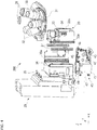
- the lower surface of the pillar 20 (pillar lower part 20b) has a fastening screw 20a screwed into a threaded hole 11a provided on the upper surface of the base 11 or a threaded hole 91b provided on the upper surface of the pillar spacer 91 (see Fig. 1 ).
- the upper surface of the base 11 has a pin 11b insertable into a hole (not shown in the drawings) provided on the upper surface of the pillar 20 (pillar lower part 20b) or the lower surface of the pillar spacer 91.
- the pin 11b is inserted into a hole (not shown in the drawings), whereby the pillar 20 (pillar lower part 20b) is positioned on the base 11.
- the stage 50 is attached to a side surface on the +X side of the pillar 20 (pillar lower part 20b) above the nosepiece unit 200.
- the stage 50 holds a specimen.
- the stage 50 has a through hole extending in the up/down direction (the Z direction).
- a specimen is held by the stage 50 in a state in which the specimen is placed on a transparent plate such as a glass plate or contained in a transparent container such as a glass container.
- the glass plate or the glass container is held on the stage 50 such that the specimen is disposed in the through hole.
- the stage 50 may have a jig for holding the glass plate, the glass container, or the like at a predetermined position.
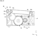
- Objective lenses having the function of correcting aberration (aberration correction objective lenses) 39 may be mounted on the nosepiece 31, in addition to the objective lenses 32.
- Each of the aberration correction objective lenses 39 is, for example, an objective lens including, for example, a lens for correcting chromatic aberration, a lens for correcting spherical aberration, a lens for correcting astigmatism, and a lens for correcting field curvature.
- the number of lenses installed in one aberration correction objective lens 39 increases as the kinds of aberration to be corrected increase.
- the aberration correction objective lenses 39 thus have a larger weight than that of the objective lenses 32.
- One or more aberration correction objective lenses 39 may be mounted on one nosepiece 31.
- the nosepiece support 30 has an autofocus 38 that automatically adjusts the height in the up/down direction (the position in the optical axis AX direction) of the objective lens 32 (nosepiece 31).
- the autofocus 38 drives the driver 40 described later such that a specimen is arranged at a focus position of the objective lens 32 selected by the nosepiece 31.
- the autofocus 38 includes, for example, a focus-detecting light source (not shown in the drawings) that emits infrared light for measurement and a sensor (not shown in the drawings) that detects reflected light that is infrared light emitted from the focus-detecting light source and reflected by a specimen or a glass plate. Examples of the kind of the light source include LED light source, LD light source, and laser light source.
- the autofocus 38 is not essential and may be disposed in the microscope separately from the nosepiece support 30.
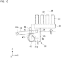
- Fig. 9 is a diagram illustrating an example of the operation of the driver 40 in a state in which the link rod 44 is elevated.
- Fig. 9 illustrates a state in which the cam follower 45 abuts on the largest diameter part 43b of the cam 43.
- the cam follower 45 is in contact with the largest diameter part 43b of the cam 43.
- the link rod 44 is thus disposed at a rotation position where the distal end side is at the highest position. Accordingly, the contact part 46 on the distal end side of the link rod 44 is also at the highest position.
- the objective lens 32 can be moved along the optical axis AX by manipulating the operation knob 14.
- the user manipulates the operation knob 14 to move the objective lens 32 while looking through the eyepieces 13 (see Fig. 1 and Fig. 2 ) so that the objective lens 32 can be disposed at a desired focus position for the specimen.
- the driver 40 may be driven based on the detection result of the autofocus 38 to adjust the position of the nosepiece support 30 (objective lens 32).
- the driver 40 allows the cam 43 to rotate the link rod 44 and elevate or lower the contact part 46 in the foregoing embodiment, the present invention is not limited thereto.
- the cam surface of the cam 43 may directly push the drive force receiver 34 of the nosepiece support 30 upward.
Landscapes
- Physics & Mathematics (AREA)
- General Physics & Mathematics (AREA)
- Optics & Photonics (AREA)
- Chemical & Material Sciences (AREA)
- Analytical Chemistry (AREA)
- Microscoopes, Condenser (AREA)
Applications Claiming Priority (1)
| Application Number | Priority Date | Filing Date | Title |
|---|---|---|---|
| PCT/JP2016/080619 WO2018070048A1 (ja) | 2016-10-14 | 2016-10-14 | 顕微鏡装置、及び対物レンズユニット |
Publications (3)
| Publication Number | Publication Date |
|---|---|
| EP3528028A1 true EP3528028A1 (de) | 2019-08-21 |
| EP3528028A4 EP3528028A4 (de) | 2020-07-22 |
| EP3528028B1 EP3528028B1 (de) | 2025-12-03 |
Family
ID=61905439
Family Applications (1)
| Application Number | Title | Priority Date | Filing Date |
|---|---|---|---|
| EP16918557.6A Active EP3528028B1 (de) | 2016-10-14 | 2016-10-14 | Mikroskopvorrichtung und objektiveinheit |
Country Status (4)
| Country | Link |
|---|---|
| US (1) | US11249296B2 (de) |
| EP (1) | EP3528028B1 (de) |
| JP (1) | JP6879310B2 (de) |
| WO (1) | WO2018070048A1 (de) |
Families Citing this family (7)
| Publication number | Priority date | Publication date | Assignee | Title |
|---|---|---|---|---|
| JP6879310B2 (ja) | 2016-10-14 | 2021-06-02 | 株式会社ニコン | 顕微鏡装置 |
| CN110967816B (zh) * | 2019-11-06 | 2021-06-15 | 浙江大学 | 基于多维调节架的近红外二区宽场显微成像系统 |
| USD1057792S1 (en) * | 2021-06-30 | 2025-01-14 | Carl Zeiss Microscopy Gmbh | Microscope |
| USD1055130S1 (en) * | 2021-06-30 | 2024-12-24 | Carl Zeiss Microscopy Gmbh | Microscope |
| USD1051197S1 (en) * | 2021-06-30 | 2024-11-12 | Carl Zeiss Microscopy Gmbh | Microscope |
| CN113640231A (zh) * | 2021-09-15 | 2021-11-12 | 重庆医科大学 | 高速自动显微成像装置 |
| CN114509868B (zh) * | 2022-01-27 | 2023-05-02 | 宁波大学 | 一种精密变焦多视野显微成像装置及方法 |
Family Cites Families (14)
| Publication number | Priority date | Publication date | Assignee | Title |
|---|---|---|---|---|
| NZ203838A (en) * | 1983-04-08 | 1988-02-12 | Donald Rivers Ensor | Inverted microscope |
| US4756611A (en) * | 1984-08-31 | 1988-07-12 | Olympus Optical Co., Ltd. | Multiple-purpose microscope |
| JP2966514B2 (ja) * | 1990-11-19 | 1999-10-25 | オリンパス光学工業株式会社 | 焦準機構付き顕微鏡 |
| JPH07120825A (ja) * | 1993-10-21 | 1995-05-12 | Olympus Optical Co Ltd | 拡大撮影装置 |
| JPH1138326A (ja) * | 1997-07-17 | 1999-02-12 | Nikon Corp | 倒立顕微鏡 |
| JP3885305B2 (ja) * | 1997-08-27 | 2007-02-21 | 株式会社ニコン | 倒立顕微鏡 |
| JPH11344675A (ja) | 1998-05-29 | 1999-12-14 | Nikon Corp | 倒立顕微鏡 |
| JP5586326B2 (ja) * | 2010-05-28 | 2014-09-10 | オリンパス株式会社 | 倒立顕微鏡 |
| JP5969808B2 (ja) * | 2012-04-27 | 2016-08-17 | オリンパス株式会社 | 顕微鏡装置 |
| JP2014106291A (ja) * | 2012-11-26 | 2014-06-09 | Olympus Corp | 対物レンズ駆動機構および倒立顕微鏡 |
| AU2014302078A1 (en) * | 2013-06-28 | 2016-02-11 | Echo Laboratories | Upright and inverted microscope |
| JP6411763B2 (ja) * | 2013-07-18 | 2018-10-24 | オリンパス株式会社 | 顕微鏡システムおよび対物レンズユニット |
| JP5804154B2 (ja) * | 2014-07-14 | 2015-11-04 | 株式会社ニコン | オートフォーカス光学装置、顕微鏡 |
| JP6879310B2 (ja) | 2016-10-14 | 2021-06-02 | 株式会社ニコン | 顕微鏡装置 |
-
2016
- 2016-10-14 JP JP2018544668A patent/JP6879310B2/ja active Active
- 2016-10-14 EP EP16918557.6A patent/EP3528028B1/de active Active
- 2016-10-14 WO PCT/JP2016/080619 patent/WO2018070048A1/ja not_active Ceased
-
2019
- 2019-04-15 US US16/383,809 patent/US11249296B2/en active Active
Also Published As
| Publication number | Publication date |
|---|---|
| US20190243116A1 (en) | 2019-08-08 |
| JP6879310B2 (ja) | 2021-06-02 |
| WO2018070048A1 (ja) | 2018-04-19 |
| EP3528028A4 (de) | 2020-07-22 |
| US11249296B2 (en) | 2022-02-15 |
| EP3528028B1 (de) | 2025-12-03 |
| JPWO2018070048A1 (ja) | 2019-08-08 |
Similar Documents
| Publication | Publication Date | Title |
|---|---|---|
| US11249296B2 (en) | Microscope apparatus and objective lens unit | |
| JP6411763B2 (ja) | 顕微鏡システムおよび対物レンズユニット | |
| JP6280770B2 (ja) | 測定装置 | |
| CA2676158A1 (en) | System and method for adjusting the spherical aberration of objective lenses | |
| US20190219808A1 (en) | Observation device | |
| TW554177B (en) | Microscope unit | |
| US9645345B2 (en) | Optical element alignment and retention for optical instruments | |
| JP2014160209A (ja) | ステージ装置 | |
| JP4539275B2 (ja) | ユニット型顕微鏡装置 | |
| JP6391328B2 (ja) | 顕微鏡システムおよび補正環操作装置 | |
| US20180045940A1 (en) | Microscope and optical unit | |
| US9989748B1 (en) | Upright and inverted microscope | |
| US9952419B2 (en) | Objective lens changer for optical instruments | |
| US7289265B2 (en) | Microscope illumination intensity measuring device | |
| EP2594982A1 (de) | Mikroskopsystem | |
| JP2018063408A (ja) | 上下動駆動装置及び顕微鏡装置 | |
| JPWO2018070049A1 (ja) | 顕微鏡装置、画像処理方法、及び処理装置 | |
| JP4837349B2 (ja) | 顕微鏡 | |
| JP2015127775A (ja) | 拡大観察装置 | |
| JP3125124U (ja) | 赤外顕微鏡 | |
| JP2018063409A (ja) | 照明装置、及び顕微鏡 | |
| JP2009098229A (ja) | 顕微鏡用照明制御装置、顕微鏡用照明装置、顕微鏡、および、プログラム | |
| JP2014219690A (ja) | オートフォーカス光学装置、顕微鏡 | |
| JP2010230865A (ja) | 対物レンズ、顕微鏡 | |
| JP2008175892A (ja) | 顕微鏡装置 |
Legal Events
| Date | Code | Title | Description |
|---|---|---|---|
| STAA | Information on the status of an ep patent application or granted ep patent |
Free format text: STATUS: THE INTERNATIONAL PUBLICATION HAS BEEN MADE |
|
| PUAI | Public reference made under article 153(3) epc to a published international application that has entered the european phase |
Free format text: ORIGINAL CODE: 0009012 |
|
| STAA | Information on the status of an ep patent application or granted ep patent |
Free format text: STATUS: REQUEST FOR EXAMINATION WAS MADE |
|
| 17P | Request for examination filed |
Effective date: 20190423 |
|
| AK | Designated contracting states |
Kind code of ref document: A1 Designated state(s): AL AT BE BG CH CY CZ DE DK EE ES FI FR GB GR HR HU IE IS IT LI LT LU LV MC MK MT NL NO PL PT RO RS SE SI SK SM TR |
|
| AX | Request for extension of the european patent |
Extension state: BA ME |
|
| DAV | Request for validation of the european patent (deleted) | ||
| DAX | Request for extension of the european patent (deleted) | ||
| A4 | Supplementary search report drawn up and despatched |
Effective date: 20200619 |
|
| RIC1 | Information provided on ipc code assigned before grant |
Ipc: G02B 7/16 20060101ALI20200615BHEP Ipc: G02B 21/24 20060101ALI20200615BHEP Ipc: G02B 21/02 20060101ALI20200615BHEP Ipc: G02B 21/00 20060101AFI20200615BHEP Ipc: G02B 7/04 20060101ALI20200615BHEP |
|
| STAA | Information on the status of an ep patent application or granted ep patent |
Free format text: STATUS: EXAMINATION IS IN PROGRESS |
|
| 17Q | First examination report despatched |
Effective date: 20220412 |
|
| P01 | Opt-out of the competence of the unified patent court (upc) registered |
Effective date: 20230517 |
|
| REG | Reference to a national code |
Ref country code: DE Ref legal event code: R079 Free format text: PREVIOUS MAIN CLASS: G02B0021000000 Ipc: G02B0007000000 Ref document number: 602016094282 Country of ref document: DE |
|
| GRAP | Despatch of communication of intention to grant a patent |
Free format text: ORIGINAL CODE: EPIDOSNIGR1 |
|
| STAA | Information on the status of an ep patent application or granted ep patent |
Free format text: STATUS: GRANT OF PATENT IS INTENDED |
|
| RIC1 | Information provided on ipc code assigned before grant |
Ipc: G02B 7/00 20060101AFI20250630BHEP Ipc: G02B 21/00 20060101ALI20250630BHEP Ipc: G02B 7/04 20060101ALI20250630BHEP Ipc: G02B 7/16 20060101ALI20250630BHEP Ipc: G02B 21/02 20060101ALI20250630BHEP Ipc: G02B 21/24 20060101ALI20250630BHEP |
|
| INTG | Intention to grant announced |
Effective date: 20250714 |
|
| RAP3 | Party data changed (applicant data changed or rights of an application transferred) |
Owner name: NIKON CORPORATION |
|
| RIN1 | Information on inventor provided before grant (corrected) |
Inventor name: AOYAMA, KAZUMASA |
|
| GRAS | Grant fee paid |
Free format text: ORIGINAL CODE: EPIDOSNIGR3 |
|
| GRAA | (expected) grant |
Free format text: ORIGINAL CODE: 0009210 |
|
| STAA | Information on the status of an ep patent application or granted ep patent |
Free format text: STATUS: THE PATENT HAS BEEN GRANTED |
|
| AK | Designated contracting states |
Kind code of ref document: B1 Designated state(s): AL AT BE BG CH CY CZ DE DK EE ES FI FR GB GR HR HU IE IS IT LI LT LU LV MC MK MT NL NO PL PT RO RS SE SI SK SM TR |
|
| REG | Reference to a national code |
Ref country code: CH Ref legal event code: F10 Free format text: ST27 STATUS EVENT CODE: U-0-0-F10-F00 (AS PROVIDED BY THE NATIONAL OFFICE) Effective date: 20251203 Ref country code: GB Ref legal event code: FG4D |
|
| REG | Reference to a national code |
Ref country code: DE Ref legal event code: R096 Ref document number: 602016094282 Country of ref document: DE |
|
| REG | Reference to a national code |
Ref country code: IE Ref legal event code: FG4D |