EP3528028A1 - Microscope apparatus and objective lens unit - Google Patents
Microscope apparatus and objective lens unit Download PDFInfo
- Publication number
- EP3528028A1 EP3528028A1 EP16918557.6A EP16918557A EP3528028A1 EP 3528028 A1 EP3528028 A1 EP 3528028A1 EP 16918557 A EP16918557 A EP 16918557A EP 3528028 A1 EP3528028 A1 EP 3528028A1
- Authority
- EP
- European Patent Office
- Prior art keywords
- objective lens
- base
- pillar
- nosepiece
- disposed
- Prior art date
- Legal status (The legal status is an assumption and is not a legal conclusion. Google has not performed a legal analysis and makes no representation as to the accuracy of the status listed.)
- Pending
Links
Images


Classifications
-
- G—PHYSICS
- G02—OPTICS
- G02B—OPTICAL ELEMENTS, SYSTEMS OR APPARATUS
- G02B21/00—Microscopes
- G02B21/24—Base structure
- G02B21/241—Devices for focusing
-
- G—PHYSICS
- G02—OPTICS
- G02B—OPTICAL ELEMENTS, SYSTEMS OR APPARATUS
- G02B21/00—Microscopes
-
- G—PHYSICS
- G02—OPTICS
- G02B—OPTICAL ELEMENTS, SYSTEMS OR APPARATUS
- G02B21/00—Microscopes
- G02B21/0004—Microscopes specially adapted for specific applications
- G02B21/0088—Inverse microscopes
-
- G—PHYSICS
- G02—OPTICS
- G02B—OPTICAL ELEMENTS, SYSTEMS OR APPARATUS
- G02B21/00—Microscopes
- G02B21/02—Objectives
-
- G—PHYSICS
- G02—OPTICS
- G02B—OPTICAL ELEMENTS, SYSTEMS OR APPARATUS
- G02B21/00—Microscopes
- G02B21/06—Means for illuminating specimens
-
- G—PHYSICS
- G02—OPTICS
- G02B—OPTICAL ELEMENTS, SYSTEMS OR APPARATUS
- G02B21/00—Microscopes
- G02B21/24—Base structure
- G02B21/248—Base structure objective (or ocular) turrets
-
- G—PHYSICS
- G02—OPTICS
- G02B—OPTICAL ELEMENTS, SYSTEMS OR APPARATUS
- G02B21/00—Microscopes
- G02B21/24—Base structure
- G02B21/26—Stages; Adjusting means therefor
-
- G—PHYSICS
- G02—OPTICS
- G02B—OPTICAL ELEMENTS, SYSTEMS OR APPARATUS
- G02B7/00—Mountings, adjusting means, or light-tight connections, for optical elements
- G02B7/008—Mountings, adjusting means, or light-tight connections, for optical elements with means for compensating for changes in temperature or for controlling the temperature; thermal stabilisation
-
- G—PHYSICS
- G02—OPTICS
- G02B—OPTICAL ELEMENTS, SYSTEMS OR APPARATUS
- G02B7/00—Mountings, adjusting means, or light-tight connections, for optical elements
- G02B7/02—Mountings, adjusting means, or light-tight connections, for optical elements for lenses
- G02B7/04—Mountings, adjusting means, or light-tight connections, for optical elements for lenses with mechanism for focusing or varying magnification
- G02B7/09—Mountings, adjusting means, or light-tight connections, for optical elements for lenses with mechanism for focusing or varying magnification adapted for automatic focusing or varying magnification
-
- G—PHYSICS
- G02—OPTICS
- G02B—OPTICAL ELEMENTS, SYSTEMS OR APPARATUS
- G02B7/00—Mountings, adjusting means, or light-tight connections, for optical elements
- G02B7/02—Mountings, adjusting means, or light-tight connections, for optical elements for lenses
- G02B7/14—Mountings, adjusting means, or light-tight connections, for optical elements for lenses adapted to interchange lenses
- G02B7/16—Rotatable turrets
Definitions
- the lower surface of the pillar 20 (pillar lower part 20b) has a fastening screw 20a screwed into a threaded hole 11a provided on the upper surface of the base 11 or a threaded hole 91b provided on the upper surface of the pillar spacer 91 (see Fig. 1 ).
- the upper surface of the base 11 has a pin 11b insertable into a hole (not shown in the drawings) provided on the upper surface of the pillar 20 (pillar lower part 20b) or the lower surface of the pillar spacer 91.
- the pin 11b is inserted into a hole (not shown in the drawings), whereby the pillar 20 (pillar lower part 20b) is positioned on the base 11.
- the stage 50 is attached to a side surface on the +X side of the pillar 20 (pillar lower part 20b) above the nosepiece unit 200.
- the stage 50 holds a specimen.
- the stage 50 has a through hole extending in the up/down direction (the Z direction).
- a specimen is held by the stage 50 in a state in which the specimen is placed on a transparent plate such as a glass plate or contained in a transparent container such as a glass container.
- the glass plate or the glass container is held on the stage 50 such that the specimen is disposed in the through hole.
- the stage 50 may have a jig for holding the glass plate, the glass container, or the like at a predetermined position.
- Objective lenses having the function of correcting aberration (aberration correction objective lenses) 39 may be mounted on the nosepiece 31, in addition to the objective lenses 32.
- Each of the aberration correction objective lenses 39 is, for example, an objective lens including, for example, a lens for correcting chromatic aberration, a lens for correcting spherical aberration, a lens for correcting astigmatism, and a lens for correcting field curvature.
- the number of lenses installed in one aberration correction objective lens 39 increases as the kinds of aberration to be corrected increase.
- the aberration correction objective lenses 39 thus have a larger weight than that of the objective lenses 32.
- One or more aberration correction objective lenses 39 may be mounted on one nosepiece 31.
- the nosepiece support 30 has an autofocus 38 that automatically adjusts the height in the up/down direction (the position in the optical axis AX direction) of the objective lens 32 (nosepiece 31).
- the autofocus 38 drives the driver 40 described later such that a specimen is arranged at a focus position of the objective lens 32 selected by the nosepiece 31.
- the autofocus 38 includes, for example, a focus-detecting light source (not shown in the drawings) that emits infrared light for measurement and a sensor (not shown in the drawings) that detects reflected light that is infrared light emitted from the focus-detecting light source and reflected by a specimen or a glass plate. Examples of the kind of the light source include LED light source, LD light source, and laser light source.
- the autofocus 38 is not essential and may be disposed in the microscope separately from the nosepiece support 30.
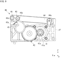
- Fig. 9 is a diagram illustrating an example of the operation of the driver 40 in a state in which the link rod 44 is elevated.
- Fig. 9 illustrates a state in which the cam follower 45 abuts on the largest diameter part 43b of the cam 43.
- the cam follower 45 is in contact with the largest diameter part 43b of the cam 43.
- the link rod 44 is thus disposed at a rotation position where the distal end side is at the highest position. Accordingly, the contact part 46 on the distal end side of the link rod 44 is also at the highest position.
- the objective lens 32 can be moved along the optical axis AX by manipulating the operation knob 14.
- the user manipulates the operation knob 14 to move the objective lens 32 while looking through the eyepieces 13 (see Fig. 1 and Fig. 2 ) so that the objective lens 32 can be disposed at a desired focus position for the specimen.
- the driver 40 may be driven based on the detection result of the autofocus 38 to adjust the position of the nosepiece support 30 (objective lens 32).
- the driver 40 allows the cam 43 to rotate the link rod 44 and elevate or lower the contact part 46 in the foregoing embodiment, the present invention is not limited thereto.
- the cam surface of the cam 43 may directly push the drive force receiver 34 of the nosepiece support 30 upward.
Landscapes
- Physics & Mathematics (AREA)
- General Physics & Mathematics (AREA)
- Optics & Photonics (AREA)
- Chemical & Material Sciences (AREA)
- Analytical Chemistry (AREA)
- Microscoopes, Condenser (AREA)
Abstract
Description
- The present invention relates to a microscope apparatus and an objective lens unit.
- As microscope apparatuses that observe a specimen, for example, those typically provided with a base, a pillar mounted on the base, a stage supported by the pillar, and a nosepiece support are known (for example, see Patent Literature 1). The nosepiece support has a nosepiece on which a plurality of objective lenses can be mounted, and the nosepiece is turned to select an objective lens to be used for observation. The nosepiece support is provided on a focusing device. A driver to move the nosepiece support upward and downward through the focusing device is disposed on the base.
- [Patent Literature 1] United States Patent No.
6, 239, 905 - According to a first aspect of the present invention, provided is a microscope apparatus including a base, a support disposed upright on the base, and an objective lens unit supported by the support and including an objective lens holder that holds an objective lens. The objective lens unit includes a drive source that moves the objective lens holder up and down and a driver that transmits a drive force of the drive source to the objective lens holder.
- According to a second aspect of the present invention, provided is an objective lens unit including an attachment and detachment mechanism that is attachable to and detachable from a base of a microscope apparatus, an objective lens holder on which an objective lens is mounted, a drive source that moves the objective lens holder up and down, and a driver that transmits a drive force of the drive source to the objective lens holder. The objective lens unit is mounted to a support disposed upright on the base.
-
-
Fig. 1 is an exploded perspective view of a microscope apparatus according to the present embodiment. -
Fig. 2 is a perspective view of an example of the microscope apparatus before a spacer is inserted. -
Fig. 3 is a perspective view of an example of an objective lens unit according to the present embodiment. -
Fig. 4 is an exploded perspective view of the objective lens unit. -
Fig. 5 is a side view of an example of a driver. -
Fig. 6 is a cross-sectional view taken along line A-A inFig. 5 . -
Fig. 7 is a diagram illustrating a link rod in a lowered state. -
Fig. 8 is a diagram schematically illustrating an example of a nosepiece support lowered. -
Fig. 9 is a diagram illustrating the link rod in an elevated state. -
Fig. 10 is a diagram schematically illustrating an example of the nosepiece support elevated. - In the microscope apparatus disclosed in Patent Literature 1 above, a spacer can be disposed between the base and the pillar in order to adjust the level position of the stage. However, when a spacer is disposed, the distance between the base having the driver thereon and the nosepiece moved by the driver increases. The configuration provided with a spacer thus involves increased shaking in the XY direction (lateral direction) of the nosepiece relative to the base. As a result, the objective lens may be displaced from the desired position, which can affect the accuracy of observation of a specimen.
- Embodiments described below provide a microscope apparatus and an objective lens unit with which a specimen can be observed accurately.
- Embodiments will be described with reference to the accompanying drawings. It should be noted that the present invention is not limited to the embodiments. The drawings are not to scale as necessary, for example, partially enlarged or enhanced. In the drawings, the directions are illustrated using the XYZ coordinate system as necessary. In each of the X direction, the Y direction, and the Z direction, the direction indicated by an arrow is a positive direction (for example, +X direction) and the opposite direction is a negative direction (for example, -X direction).
-
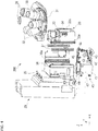
Fig. 1 is an exploded perspective view of an example of amicroscope apparatus 100.Fig. 2 is a perspective view of an example of themicroscope apparatus 100 with some components removed from the microscope apparatus inFig. 1 . As illustrated inFig. 1 andFig. 2 , themicroscope apparatus 100 is, for example, an inverted microscope. Themicroscope apparatus 100 includes abase unit 10, apillar 20, a nosepiece unit 200 (anosepiece support 30 and a driver 40) that is an objective lens unit, astage 50, a first illumination system (illumination apparatus) 60, and a second illumination system (illumination apparatus) 70. - The
base unit 10 includes abase 11, atube 12,eyepieces 13, anoperation knob 14, and aconnector 15.
Thebase 11 is placed on a plane such as a table. Optics, which are not shown in the drawings, such as a reflective mirror, a relay lens, a filter, and a prism are contained in thebase 11 and form an optical path of an observation system from the optical axis AX of anobjective lens 32 arranged at an observation position to thetube 12. These optics form part of an imaging optical system together with the optics in thetube 12, theeyepieces 13, andobjective lenses 32. Thetube 12 is detachably provided on thebase 11. Thetube 12 depicted inFig. 1 is detached upward from thebase 11. Thetube 12 contains a variety of optics such as a plurality of lenses, a filter or a prism. These optics form part of the imaging optical system as described above. - The
eyepieces 13 are mounted at the top of thetube 12. Theeyepieces 13 can be replaced from thetube 12. Theeyepieces 13 may have any desired construction. Theeyepieces 13 are used for the user to visually confirm an image. Although not shown, instead of theeyepieces 13, an image may be acquired by an imager (image sensor) such as a complementary metal oxide semiconductor (CMOS) or a charge coupled device (CCD). Alternatively, the optical path of the imaging optical system may be partially split so that one may be connected to theeyepieces 13 and the other may be connected to the imager. An image acquired by the imager may be displayed on a display device such as a liquid crystal display or may be captured by a processing device such as a personal computer for image processing. - The
operation knob 14 is provided on thebase 11. Theoperation knob 14 is disposed on a side surface of thebase 11, for example, so as to be manipulated by hand by the user looking through theeyepieces 13. Theoperation knob 14 is provided so as to be rotatable to set the amount of drive by thedriver 40 in accordance with the rotation position (or the amount of rotation) or to drive or stop anelectric drive source 41 of thedriver 40. The height of the nosepiece support 30 (the position in the Z direction) thus can be adjusted by manipulating theoperation knob 14. Theoperation knob 14 is not necessarily rotatable. For example, a button may be provided that electrically drives thedriver 40 so as to move thenosepiece support 30 upward or downward. - The
connector 15 is a terminal formed in an exposed state on the upper surface of thebase 11 to enable electrical connection. Theconnector 15 is disposed at a part connected to thepillar 20. Theconnector 15 of thebase 11 is provided on the rear surface region side on the upper surface of thebase 11 or on the upper surface of thebase 11 on the back side with respect to the observer side (user side). The rear surface region side on the upper surface of thebase 11 or the back side with respect to the observer side on the upper surface of thebase 11 is a region on the -X side with respect to the center of the upper surface of thebase 11 and including the part to which theconnector 15 illustrated inFig. 1 is provided. Since theconnector 15 is thus provided on the rear surface region side on the upper surface of the base 11 or on the back side with respect to the observer side on the upper surface of thebase 11, and a base-side connector 93 (described later) connectable to theconnector 15 is also provided on aspacer 90 described later, theconnector 15 can be disposed based on the mounting position of the spacer 90 (the mounting position where thespacer 90 does not interfere when thespacer 90 is mounted on the microscope apparatus 100). Theconnector 15 is electrically connected to a board M disposed on the base 11 through alead wire 15a. The board M is electrically connected to theoperation knob 14 through alead wire 15b. The board M includes, for example, a central processing unit (CPU) or a memory to configure a controller of the components including thedriver 40. The board M receives information input by manipulating theoperation knob 14 through thelead wire 15b and outputs a signal for controlling thedriver 40, electric power for driving thedriver 40, and the like to theconnector 15 through thelead wire 15a. - The
pillar 20 has a pillar lower part (support) 20b disposed upright on thebase 11. The pillarlower part 20b is attached to the base 11 with a pillar spacer (spacer 90) 91 interposed therebetween, which will be described later. The pillar 20 (pillarlower part 20b) is disposed to extend upward (+Z direction) from the base 11 (pillar spacer 91). The pillar 20 (pillarlower part 20b) may be attached to thebase 11 without thespacer 90. As illustrated inFig. 2 , the pillar 20 (pillarlower part 20b) is attached to the upper surface of thebase 11. The lower surface of the pillar 20 (pillarlower part 20b) has afastening screw 20a screwed into a threadedhole 11a provided on the upper surface of the base 11 or a threadedhole 91b provided on the upper surface of the pillar spacer 91 (seeFig. 1 ).
The upper surface of thebase 11 has apin 11b insertable into a hole (not shown in the drawings) provided on the upper surface of the pillar 20 (pillarlower part 20b) or the lower surface of thepillar spacer 91. Thepin 11b is inserted into a hole (not shown in the drawings), whereby the pillar 20 (pillarlower part 20b) is positioned on thebase 11. While in this state, thefastening screw 20a is screwed into the threadedhole 11a or the threadedhole 91b, so that the pillar 20 (pillarlower part 20b) is attached to thebase 11. The pillarlower part support 20b is a part of an illumination pillar including the first illumination system (illumination apparatus) 60 or is a member that supports an illumination pillar. - The
pillar 20 has aconnector 21 on its lower surface. When thepillar 20 is directly mounted on the base 11 (the case illustrated inFig. 2 ), theconnector 21 comes into contact with theconnector 15 of the base 11 to be electrically connected to theconnector 15. When thepillar 20 is mounted on the base 11 with thepillar spacer 91 interposed therebetween (the case illustrated inFig. 1 ), theconnector 21 comes into contact with a pillar-side connector 94 described later to be electrically connected to the pillar-side connector 94. As will be described later, in thepillar spacer 91, the pillar-side connector 94 is electrically connected to theconnector 15 of thebase 11. Thepillar 20 thus ensures electrical connection between theconnector 21 and theconnector 15 of the base 11 even when thepillar spacer 91 is used. - The
connector 21 is electrically connected to the drive source of thedriver 40, for example, through a lead wire (not shown in the drawings). Theconnector 21 may be electrically connected to thefirst illumination system 60 or thestage 50 described later or the like to transmit a signal controlling them or supply electricity for driving. Theconnectors pillar 20 is mounted. For example, when thepillar 20 is mounted, flat surfaces may come into contact with each other to ensure electrical connection. Alternatively, for example, one of the connectors may be shaped like a pin and the other may be shaped like a hole, so that the pin is inserted into the hole to ensure electrical connection when thepillar 20 is mounted. - The nosepiece unit 200 (the
nosepiece support 30 and the driver 40) is attached to a side surface on the +X side of the pillar 20 (pillarlower part 20b) and is disposed to extend from the pillar 20 (pillarlower part 20b) in the +X direction. The side surface on the +X side of thepillar 20 is a surface facing the direction in which theeyepieces 13 are installed and corresponds to the observer side during observation. Thenosepiece unit 200 therefore is disposed in a space between thepillar 20 and the eyepieces 13 (tube 12) in the X direction. The detail of thenosepiece unit 200 will be described later with reference to other drawings. - The
stage 50 is attached to a side surface on the +X side of the pillar 20 (pillarlower part 20b) above thenosepiece unit 200. Thestage 50 holds a specimen. Thestage 50 has a through hole extending in the up/down direction (the Z direction). A specimen is held by thestage 50 in a state in which the specimen is placed on a transparent plate such as a glass plate or contained in a transparent container such as a glass container. The glass plate or the glass container is held on thestage 50 such that the specimen is disposed in the through hole. Thestage 50 may have a jig for holding the glass plate, the glass container, or the like at a predetermined position. - The
stage 50 may be movable in the X direction and the Y direction (the horizontal direction or the direction orthogonal to the optical axis AX). Thestage 50 may be movable in the up/down direction (the Z direction) or the direction along the optical axis AX. Such movement of thestage 50 may be performed manually by the user or may be performed using a drive source such as an electric motor. When a drive source is used, a control signal as for the amount of movement, etc. and power supply to the drive source may be given from the base 11 through theconnector 21 of thepillar 20. An operation knob to operate the movement of thestage 50 may be provided at thebase 11. - The
first illumination system 60 is attached to the top of thepillar 20. The emission side of thefirst illumination system 60 is disposed above thestage 50. Thefirst illumination system 60 provides transmitted illumination to the specimen held on thestage 50. Thefirst illumination system 60 includes, for example, a light source emitting white light or visible light (light in a broad range of wavelengths), such as a halogen lamp or a white LED, and an illumination optical system including optics such as a relay lens, a variety of filters, an aperture stop, and a field stop to guide light emitted from the light source. Thefirst illumination system 60 emits illumination light along the optical axis AX. However, embodiments are not limited thereto, and illumination light may be emitted at an angle relative to the optical axis AX. - The illumination light emitted from the
first illumination system 60 illuminates the specimen from above (+Z side). The transmitted light (observation light) transmitted through the specimen passes through the optical path in thebase 11 and thetube 12 through theobjective lenses 32 described later and is guided to theeyepieces 13. The user can look through theeyepieces 13 to observe the specimen held on thestage 50 with illumination light from thefirst illumination system 60. An imaging device including an imager may be disposed so that the imager receives observation light. Thefirst illumination system 60 does not necessarily include a light source. For example, a light source may be disposed outside thefirst illumination system 60 to supply illumination light to thefirst illumination system 60, for example, through an optical fiber. The inclusion of thefirst illumination system 60 is optional and thefirst illumination system 60 may be eliminated. - The
second illumination system 70 is attached to a side surface on the -X side of the pillar 20 (pillarlower part 20b). The emission side of thesecond illumination system 70 is disposed below thestage 50 and thenosepiece unit 200. Thepillar 20 has a through hole to allow light from thesecond illumination system 70 to pass through.
Thesecond illumination system 70 provides epi-illumination to the specimen held on thestage 50. In addition to epi-illumination, thesecond illumination system 70 illuminates a fluorescent substance with activation light or excitation light when themicroscope apparatus 100 is used as a fluorescence microscope. Thesecond illumination system 70 is interchangeable for epi-illumination or for fluorescent observation. - When the
second illumination system 70 provides epi-illumination, thesecond illumination system 70 includes, for example, a light source that emits white light or visible light (light in a broad range of wavelengths), such as a halogen lamp or a white LED, and an illumination optical system including optics such as a relay lens, a variety of filters, an aperture stop, and a field stop to guide light emitted from the light source. Thesecond illumination system 70 includes amirror 72. When thesecond illumination system 70 provides epi-illumination, for example, a semitransparent mirror is used as themirror 72. Themirror 72 is disposed on the optical axis AX and contained in anoptical unit 72a provided under thenosepiece unit 200. - Illumination light emitted from the
second illumination system 70 is reflected by themirror 72 and illuminates a specimen from below (-Z side). The reflected light from the specimen by the illumination light is transmitted through themirror 72, passes through the optical path in thebase 11 and thetube 12 through theobjective lenses 32 described later, and is guided to theeyepieces 13. The user can look through theeyepieces 13 to observe the specimen held on thestage 50 with illumination light from thesecond illumination system 70. Thesecond illumination system 70 does not necessarily include a light source for epi-illumination. For example, a light source may be disposed outside thesecond illumination system 70 to supply illumination light to thesecond illumination system 70, for example, through an optical fiber. - When the
microscope apparatus 100 is used as a fluorescence microscope, thesecond illumination system 70 may emit either activation light that activates a fluorescent substance included in a specimen held on thestage 50 or excitation light that excites a fluorescent substance to produce fluorescence. The other one of activation light and excitation light is emitted from athird illumination system 80 described later. Thesecond illumination system 70 includes a laser light source that emits light with wavelengths corresponding to activation light or excitation light and an illumination optical system including optics such as a relay lens, a variety of filters, an aperture stop, and a field stop to guide light emitted from the laser light source. - When the
second illumination system 70 emits activation light or excitation light, for example, a dichroic mirror is used as themirror 72. The dichroic mirror reflects light with wavelengths of activation light or excitation light and transmits wavelengths of fluorescence. For example, when light emitted from thesecond illumination system 70 is activation light, the activation light is reflected by themirror 72 and illuminates a specimen from below (-Z side). After emission of activation light or simultaneously with emission of activation light, excitation light is emitted from thethird illumination system 80 described later to irradiate a specimen. - The fluorescent substance in a specimen is excited by radiation of activation light and excitation light to emit fluorescence. The fluorescence is transmitted through the
mirror 72, passes through the optical path in thebase 11 and thetube 12 through theobjective lenses 32 described later, and is guided to theeyepieces 13. The user can look through theeyepieces 13 to observe the fluorescence produced from the specimen. Activation light may be emitted from thethird illumination system 80 and excitation light may be emitted from thesecond illumination system 70. Thesecond illumination system 70 may be used, instead of thethird illumination system 80, to switch the light source so that activation light and excitation light are emitted from thesecond illumination system 70 in a switchable manner. - The
second illumination system 70 does not necessarily include a light source that emits activation light or excitation light. For example, a light source may be disposed outside thesecond illumination system 70 to supply activation light or excitation light to thesecond illumination system 70, for example, through an optical fiber. The inclusion of thesecond illumination system 70 is optional and thesecond illumination system 70 may be eliminated. - The
microscope apparatus 100 is used with thepillar 20 mounted on thebase 11, as illustrated inFig. 2 . However, as described above, when themicroscope apparatus 100 is used as a fluorescence microscope or when it is desired that the position of thestage 50 be lifted upward, as illustrated inFig. 1 , thespacer 90 is disposed between the base 11 and thepillar 20. As illustrated inFig. 2 , thepillar 20 is fixed to the upper surface of the base 11 with a fastener (not shown in the drawings) such as a bolt. When thespacer 90 is mounted, thepillar 20 can be removed from the base 11 by removing the fastener. - As illustrated in
Fig. 2 , asupport 12a is provided on the -X side of thetube 12 to support a supportedpart 50a provided on the +X side of thestage 50. By thus supporting the supportedpart 50a by thesupport 12a, shaking or vibration of thestage 50 is suppressed. Thesupport 12a and the supportedpart 50a are fixed to each other with a fastener (not shown in the drawings) such as a bolt. When thespacer 90 is mounted, the supportedpart 50a can be detached from thesupport 12a by removing the fastener. - As illustrated in
Fig. 1 , apillar spacer 91 and astage spacer 92 are used as thespacer 90. Thespacer 90 is used when thethird illumination system 80 is mounted on themicroscope apparatus 100 or when thestage 50 is adjusted upward (+Z direction) relative to thebase unit 10, and those spacers have the same size in the Z direction. - The pillar spacer 91 is disposed between the base 11 and the
pillar 20. The pillar spacer 91 has a base-side connector 93 and a pillar-side connector 94. The base-side connector 93 is a terminal electrically connected to theconnector 15 of the base 11 when thepillar spacer 91 is mounted on thebase 11. The pillar-side connector 94 is a terminal electrically connected to theconnector 21 of thepillar 20 when thepillar 20 is mounted on thepillar spacer 91. - The pillar spacer 91 has a
lead wire 91c that electrically connects the base-side connector 93 with the pillar-side connector 94. Thus, when thepillar spacer 91 is mounted between the base 11 and thepillar 20, theconnector 15 is electrically connected with the base-side connector 93 and the pillar-side connector 94 is electrically connected with theconnector 21. As a result, a control signal and power supply from the board M is fed to theconnector 21 through the base-side connector 93, thelead wire 91c, and the pillar-side connector 94 to enable the control of thedriver 40 or other components as described above. - The
stage spacer 92 is formed, for example, in a rectangular plate shape. Thestage spacer 92 is disposed between thesupport 12a of thetube 12 and the supportedpart 50a of thestage 50. Thestage spacer 92 is disposed on the +X side of thenosepiece unit 200. Thestage spacer 92 can support the supportedpart 50a to suppress shaking or vibration of thestage 50 even when thepillar spacer 91 is mounted to lift thestage 50 upward. - The pillar spacer 91 has a
fastening screw 91a that can be screwed into the threadedhole 11a of thebase 11, on its lower surface, and has a threadedhole 91b into which thefastening screw 20a of thepillar 20 can be screwed, on its upper surface. Thepin 11b of thebase 11 is inserted into a hole (not shown in the drawings) on the lower surface of thepillar spacer 91, whereby thepillar spacer 91 is positioned on thebase 11. The upper surface of thepillar spacer 91 further has apin 91d that can be inserted into a hole (not shown in the drawings) provided on the lower surface of thepillar 20. Thepin 91d is inserted into the hole on the lower surface of thepillar 20, whereby thepillar 20 is positioned on thepillar spacer 91. While in this state, thefastening screw 91a is screwed into the threadedhole 11a and thefastening screw 20a is screwed into the threadedhole 91b, whereby thepillar 20 is attached to the base 11 with thepillar spacer 91 interposed therebetween. Although a detailed description is omitted, thestage spacer 92 is also positioned using a pin or a hole. - For example, the
stage spacer 92 is fixed to thesupport 12a of thetube 12, and thestage spacer 92 is fixed to the supportedpart 50a of thestage 50 with a fastener (not shown in the drawings) such as a fastening screw, in the same manner as thepillar spacer 91 described above. - The
nosepiece unit 200, thestage 50, thefirst illumination system 60, and thesecond illumination system 70 are attached to thepillar 20. Therefore, when thepillar 20 is removed from thebase 11 and when thepillar 20 is attached to thepillar spacer 91, thenosepiece unit 200, thestage 50, thefirst illumination system 60, and thesecond illumination system 70 are removed or attached integrally with thepillar 20. Thenosepiece unit 200, thestage 50, and thesecond illumination system 70 are attached to the pillarlower part 20b. Therefore, while holding thenosepiece unit 200, thestage 50, and thesecond illumination system 70, the pillarlower part 20b is separable from the pillar upper part supporting thefirst illumination system 60. Thebase 11 and the objective lens unit (nosepiece unit 200) are separable. - As illustrated in
Fig. 1 , the third illumination system (illumination apparatus) 80 can be mounted on thepillar spacer 91. Thethird illumination system 80 is attached to a side surface on the -X side of thepillar spacer 91. Thethird illumination system 80 is disposed below (-Z side) thesecond illumination system 70. The pillar spacer 91 has a through hole to allow light from thethird illumination system 80 to pass through. When themicroscope apparatus 100 is used as a fluorescence microscope, thethird illumination system 80 emits either activation light that activates a fluorescent substance included in a specimen held on thestage 50 or excitation light that excites a fluorescent substance to produce fluorescence, as described above. - The
third illumination system 80 includes a laser light source that emits light with wavelengths corresponding to activation light or excitation light and an illumination optical system including optics such as a relay lens, a variety of filters, an aperture stop, and a field stop to guide light emitted from the laser light source. Thethird illumination system 80 includes amirror 82. When thethird illumination system 80 emits activation light or excitation light, for example, a dichroic mirror may be used as themirror 82, in the same manner as themirror 72 of thesecond illumination system 70 described above. Themirror 82 is disposed on the optical axis AX and contained in an optical unit 82a provided under theoptical unit 72a including themirror 72. - For example, when light emitted from the
third illumination system 80 is excitation light, the excitation light is reflected by themirror 82 and then transmitted through the mirror 72 (or themirror 72 is retreated from the optical axis AX) to irradiate a specimen from below (-Z side). Fluorescence from a fluorescent substance in the specimen is transmitted through themirror 82, passes through the optical path in thebase 11 and thetube 12 through theobjective lenses 32 described later, and is guided to theeyepieces 13. The user can look through theeyepieces 13 to observe fluorescence from the specimen, as described above. - The
third illumination system 80 may be used, instead of thesecond illumination system 70, to switch the light source so that activation light and excitation light are emitted from thethird illumination system 80 in a switchable manner. Thethird illumination system 80 does not necessarily include a light source. For example, the light source may be disposed outside thesecond illumination system 70 to supply white light, activation light, or excitation light to thethird illumination system 80, for example, through an optical fiber. Even when thepillar spacer 91 is mounted, the inclusion of thethird illumination system 80 is optional and thethird illumination system 80 may be eliminated. - The
third illumination system 80 may provide epi-illumination to the specimen held on thestage 50. Thethird illumination system 80 is interchangeable for epi-illumination or for fluorescence observation. When thethird illumination system 80 provides epi-illumination, a configuration similar to thesecond illumination system 70 above is employed. In such case, a semitransparent mirror, for example, is used as themirror 82. - The
nosepiece unit 200 will now be described. Thenosepiece unit 200 is attached to a side surface on the +X side of thepillar 20.Fig. 3 is a perspective view of an example of thenosepiece unit 200 according to an embodiment.Fig. 4 is an exploded perspective view of thenosepiece unit 200. As illustrated inFig. 3 andFig. 4 , thenosepiece unit 200 includes thenosepiece support 30 and thedriver 40. - The
nosepiece support 30 supports a nosepiece (objective lens holder) 31. A plurality ofobjective lenses 32 are mounted on thenosepiece 31. Thenosepiece 31 is provided so as to be rotatable, for example, in the direction around the axis at an angle relative to the Z axis. Thenosepiece 31 can be turned so that one of theobjective lenses 32 is disposed on the optical axis AX (observation position), whereby theobjective lenses 32 can be switched. Lenses for aberration correction may be mounted on thenosepiece 31, in addition to theobjective lenses 32. - Objective lenses having the function of correcting aberration (aberration correction objective lenses) 39 may be mounted on the
nosepiece 31, in addition to theobjective lenses 32. Each of the aberration correctionobjective lenses 39 is, for example, an objective lens including, for example, a lens for correcting chromatic aberration, a lens for correcting spherical aberration, a lens for correcting astigmatism, and a lens for correcting field curvature. The number of lenses installed in one aberration correctionobjective lens 39 increases as the kinds of aberration to be corrected increase. The aberration correctionobjective lenses 39 thus have a larger weight than that of theobjective lenses 32. One or more aberration correctionobjective lenses 39 may be mounted on onenosepiece 31. - The
nosepiece 31 may be turned manually by the user or may be turned by a drive source such as an electric motor. The drive source is disposed, for example, in thenosepiece support 30. A control signal or power supply to the drive source may be given from the base 11 through thepillar 20, in the same manner as thedriver 40 described later. When thenosepiece 31 is turned by an electric motor or the like, the operation knob may be disposed on the base 11 or may be disposed, for example, in a remote control unit at a distance from themicroscope apparatus 100. Thenosepiece 31 has any desired configuration that holds the turned position and holds the selectedobjective lens 32 on the optical axis AX. - The
nosepiece support 30 includes anosepiece receptacle 33 and adrive force receiver 34. Thenosepiece 31 is mounted on thenosepiece receptacle 33. Thenosepiece 31 can be fixed to thenosepiece receptacle 33 with an anchor (not shown in the drawings) such as a bolt and replaced with another nosepiece by removing the bolt. Thenosepiece 31 attached to thenosepiece receptacle 33 is kept rotatable. Thedrive force receiver 34 is attached to a side surface on the -Y side of thenosepiece receptacle 33. Thedrive force receiver 34 has a protrusion protruding in the -Y direction. The protrusion is a portion receiving a drive force from thedriver 40. Thenosepiece receptacle 33 has a throughhole 33b to allow light from thesecond illumination system 70 to pass through. - The
nosepiece receptacle 33 is held by thepillar 20 with abase 35 and aguide 36 interposed therebetween. Thebase 35 is attached to a side surface on the +X side of thepillar 20 with an anchor (not shown in the drawings) such as a bolt. Theguide 36 is attached to a side surface on the +X side of the base 35 with an anchor (not shown in the drawings) such as a bolt. The +X side of theguide 36 has a shape in which thenosepiece receptacle 33 is partially fitted so that thenosepiece receptacle 33 is guided in the up/down direction (optical axis AX direction). Thenosepiece receptacle 33 is held by thepillar 20 so as to be movable in the up/down direction through theguide 36. -
Bearings 37 are disposed between thenosepiece receptacle 33 and theguide 36. Twobearings 37 are disposed such that thenosepiece receptacle 33 is sandwiched therebetween in the Y direction. Thebearings 37 are formed such that a plurality of roller bearings are arranged in the up/down direction with their orientations alternately changed.Protrusions 33a extending in the up/down direction are provided on the side surfaces on the +Y side and on the -Y side of thenosepiece receptacle 33. Theprotrusions 33a come into contact with therespective bearings 37 to facilitate the movement of thenosepiece receptacle 33. Thebearings 37 guide theprotrusions 33a to restrict the movement of thenosepiece receptacle 33 in the X direction. - The
nosepiece support 30 is movable in the up/down direction as described above and receives a drive force from thedriver 40 described later at thedrive force receiver 34 to move in the up/down direction. In other words, thenosepiece support 30 moves in the up/down direction to move theobjective lens 32 closer to or away from the stage 50 (seeFig. 1 orFig. 2 ). As illustrated inFig. 4 , ascrew 36a protruding in the +X direction is provided on a surface on the +X side between two guides 36. Thescrew 36a is inserted into a slot (not shown in the drawings) in the up/down direction provided on a surface on the -X side of thenosepiece receptacle 33. The movement range (stroke) of thenosepiece support 30 in the up/down direction is set by thescrew 36a and the slot. The movement range is set, for example, such that the upper limit is reached before thecam 43 of thedriver 40 described later rotates to reach alargest diameter part 43b. Breakage of thedriver 40, thenosepiece support 30, and the like is thereby prevented. - The
nosepiece support 30 has anautofocus 38 that automatically adjusts the height in the up/down direction (the position in the optical axis AX direction) of the objective lens 32 (nosepiece 31). Theautofocus 38 drives thedriver 40 described later such that a specimen is arranged at a focus position of theobjective lens 32 selected by thenosepiece 31. Theautofocus 38 includes, for example, a focus-detecting light source (not shown in the drawings) that emits infrared light for measurement and a sensor (not shown in the drawings) that detects reflected light that is infrared light emitted from the focus-detecting light source and reflected by a specimen or a glass plate. Examples of the kind of the light source include LED light source, LD light source, and laser light source. Theautofocus 38 is not essential and may be disposed in the microscope separately from thenosepiece support 30. - The
autofocus 38 detects reflected light that is infrared light emitted from the focus-detecting light source and reflected by a specimen with the sensor and drives thedriver 40 to move theobjective lens 32 along the optical axis AX such that the specimen is arranged at the focus position of theobjective lens 32. Theautofocus 38 may have any desired configuration and is not limited to the configuration above. A switch indicating whether to operate theautofocus 38 may be disposed on the base 11 or may be disposed, for example, in a remote control unit at a distance from themicroscope apparatus 100. Examples of the light source include laser, LED, and laser diode (LD). - As illustrated in
Fig. 4 , thedriver 40 is fixed to the base 35 attached to thepillar 20 with an anchor (not shown in the drawings) such as a bolt. Thedriver 40 therefore can be replaced by removing the anchor. In the present embodiment, thedriver 40 is disposed on the -Y side of thenosepiece support 30. However, embodiments are not limited thereto depending on the configuration of the microscope. -
Fig. 5 is a side vide view of an example of thedriver 40.Fig. 6 is a cross-sectional view taken along line A-A inFig. 5 . As illustrated inFig. 5 andFig. 6 , thedriver 40 includes adrive source 41, agear train 42, acam 43, alink rod 44, acam follower 45, acontact part 46, aframe 47, and apin 49. Thepin 49 is illustrated inFig. 6 . - The
drive source 41 is supported by theframe 47. Thedrive source 41 generates a drive force for moving thenosepiece support 30 in the up/down direction (optical axis AX direction). For example, an electric motor is used as thedrive source 41. Thedrive source 41 is electrically connected to theconnector 21 of the pillar 20 (seeFig. 1 ), for example, through wiring. Thedrive source 41 is thus electrically connected to the board M (seeFig. 1 ) disposed inside thebase 11. Thedrive source 41 has anoutput shaft 41a driven to rotate. - The
gear train 42 transmits the drive force generated by thedrive source 41 to thecam 43. A plurality of gears included in thegear train 42 are supported by theframe 47 so as to be rotatable about the axis parallel to the Y direction. Thegear train 42 uses a plurality of gears for transmission to thecam 43 at a predetermined reduction ratio relative to theoutput shaft 41a. As illustrated inFig. 5 , thegear train 42 includes anoutput shaft gear 42a, afirst transmission gear 42b, asecond transmission gear 42c, athird transmission gear 42d, and acam rotating gear 42e. Theoutput shaft gear 42a, thefirst transmission gear 42b, thesecond transmission gear 42c, thethird transmission gear 42d, and thecam rotating gear 42e included in thegear train 42 are successively meshed and supported by theframe 47. - The
output shaft gear 42a is fixed to theoutput shaft 41a and rotates integrally with theoutput shaft 41a. Thefirst transmission gear 42b and thesecond transmission gear 42c are fixed to acommon shaft 42f. Thefirst transmission gear 42b, thesecond transmission gear 42c, and theshaft 42f rotate integrally. Thefirst transmission gear 42b has an outer diameter larger than that of theoutput shaft gear 42a. Thesecond transmission gear 42c has an outer diameter smaller than that of thefirst transmission gear 42b. Thefirst transmission gear 42b is meshed with theoutput shaft gear 42a. When theoutput shaft 41a rotates, the rotation is transmitted from theoutput shaft gear 42a to thefirst transmission gear 42b, and thesecond transmission gear 42c rotates integrally with the rotation of thefirst transmission gear 42b. - The
second transmission gear 42c is meshed with thethird transmission gear 42d. Thethird transmission gear 42d is rotatably supported by a shaft (not shown in the drawings). Thethird transmission gear 42d has an outer diameter larger than that of thesecond transmission gear 42c. Thethird transmission gear 42d rotates as thesecond transmission gear 42c rotates. - The
third transmission gear 42d is meshed with thecam rotating gear 42e. Thecam rotating gear 42e is rotatably supported by a shaft (not shown in the drawings). Thecam rotating gear 42e has a diameter smaller than that of thethird transmission gear 42d. Thecam rotating gear 42e is fixed to thecam 43 and rotates integrally with thecam 43. - The
cam 43 is rotatably supported on theframe 47 by a shaft (not shown in the drawings) supporting thecam rotating gear 42e. Thecam 43 can thus rotate about the Y-axis. With the rotation of theoutput shaft 41a described above, thecam 43 rotates at a predetermined reduction ratio through thegear train 42. The reduction ratio is adjusted by the outer diameter (the number of teeth) of each gear included in thegear train 42 or the number of gears to be used. For example, when theoutput shaft 41a rotates at a few thousands of revolutions per minute, the reduction ratio is set such that thecam 43 rotates at a few to a few tens of revolutions per minute. - The
cam 43 has a distance (radius) from the rotation center C1 gradually increasing about the Y-axis from asmallest diameter part 43a to alargest diameter part 43b. Astep 43c is formed between thelargest diameter part 43b and thesmallest diameter part 43a. Although the changing rate of the radius from thesmallest diameter part 43a to thelargest diameter part 43b is set constant, embodiments are not limited thereto. For example, the changing rate of the radius may be greater in the vicinity of thesmallest diameter part 43a or thelargest diameter part 43b and may be smaller at an intermediate part. - The
link rod 44 is a rod-shaped part and disposed to extend in the X direction above thegear train 42. One end side (proximal end side) in the longitudinal direction of thelink rod 44 is supported on theframe 47 by ashaft 44a. Thelink rod 44 is rotatable around theshaft 44a on the Y-axis. The other end side (distal end side) in the longitudinal direction of thelink rod 44 is thus rotatable in the direction in which thedrive force receiver 34 of thenosepiece support 30 is moved up and down. Thelink rod 44 is set such that the length in the X direction is fitted in theframe 47. Thelink rod 44 is thereby prevented from partially protruding from thedriver 40. - The
cam follower 45 is attached so as to protrude from the distal end side of thelink rod 44 in the Y direction. Thecam follower 45 is disposed above (+Z side) thecam 43 and lowers by gravity of thelink rod 44 to come into contact with thecam 43. Thecam follower 45 is pushed against the peripheral surface of thecam 43 with the rotation of thecam 43, thereby moving in the up/down direction (the Z direction). Since thecam follower 45 is provided integrally with thelink rod 44, thecam follower 45 moves in the up/down direction to allow thelink rod 44 to rotate around theshaft 44a on the Y-axis. The center C2 of thecam follower 45 is disposed so as to be shifted from the rotation center C1 of thecam 43 in the X direction. - The
cam follower 45 is a cylindrical or tubular part and rotatably attached to thelink rod 44. Thus, when thecam 43 rotates, thecam follower 45 rotates with the movement of the peripheral surface of thecam 43, so that friction between thecam follower 45 and thecam 43 can be reduced to facilitate the operation of thecam follower 45. Thecam follower 45 is not necessarily rotatable and may be a cam follower that does not rotate. Thecam follower 45 as illustrated in the drawing may be eliminated, and a part of the link rod 44 (for example, intermediate part) may serve as a part engaged with the cam. In such a case, the rotatable part as illustrated in the drawing is not necessarily employed and, for example, a plate-shaped part may be disposed so as to be fixed to thelink rod 44. - The
contact part 46 is attached so as to protrude from the distal end side of thelink rod 44 in the Y direction. Thecontact part 46 is disposed at a position in thelink rod 44 at a distance from theshaft 44a further than thecam follower 45, that is, closer to the distal end side than thecam follower 45. Thecontact part 46 is thus disposed in the longitudinal direction of thelink rod 44 together with thecam follower 45. Thecontact part 46 moves in the rotational direction around theshaft 44a of thelink rod 44 integrally with thelink rod 44 and thecam follower 45. - The
contact part 46 is disposed in contact with thedrive force receiver 34 of thenosepiece support 30. Thecontact part 46 receives the weight of thenosepiece support 30 through thedrive force receiver 34. Thecontact part 46 thus moves upward with the rotation of thelink rod 44 to apply an upward force to thedrive force receiver 34 and move thenosepiece support 30 upward. Since thecontact part 46 is disposed closer to the distal end side than thecam follower 45, the amount of movement in the up/down direction of thecontact part 46 is larger than that of thecam follower 45. Thelink rod 44 thus increases the amount of movement of thecam follower 45 to be transmitted to thecontact part 46. - The
contact part 46 is a cylindrical or tubular part similar to thecam follower 45 and rotatably attached to thelink rod 44. When moving upward, thecontact part 46 moves on the orbit around theshaft 44a of thelink rod 44 as described above. On the other hand, the nosepiece support 30 (drive force receiver 34) moves in the up/down direction (the Z direction). Accordingly, although thecontact part 46 and thedrive force receiver 34 move in different directions, since thecontact part 46 is rotatable, thecontact part 46, when moving upward, comes into contact with thedrive force receiver 34 while rotating. The friction between thecontact part 46 and thedrive force receiver 34 can thereby be reduced to facilitate the operation of thecontact part 46. Thecontact part 46 is not necessarily rotatable and may be a contact part that does not rotate. Thecontact part 46 as illustrated in the drawing may be eliminated and a part (for example, distal end portion) of thelink rod 44 may be used as a contact part. Thecam follower 45 may serve as thecontact part 46. In such a case, thecam follower 45 may be an engagement member that does not rotate as described above. - The
frame 47 is formed, for example, in a rectangular plate shape. Theframe 47 is attached to the base 35 (seeFig. 4 ) with an anchor such as a bolt. Theframe 47 is thus fixed to thepillar 20 with the base 35 interposed therebetween. Theframe 47 is fixed to thepillar 20, whereby the components in thedriver 40 are fixed to thepillar 20. Thus, by mounting theframe 47 on thebase 35, the components of thedriver 40 can be disposed at fixed positions to thepillar 20. - The
pin 49 is a rod-shaped part and disposed to extend from thenosepiece receptacle 33 of thenosepiece support 30 to be inserted into arecess 43d formed on a surface on the +Y side of thecam 43. Thepin 49 restricts the amount of thenosepiece support 30 lifted during transportation or when the user lifts thenosepiece support 30 by hand. Thenosepiece support 30 is thus restricted from moving up to the stroke upper limit and even when it falls from that position, damage (for example, dimple) to thegear train 42 or thecam 43 is prevented. - The rotation of the
cam 43 may be restricted by thepin 49. For example, the amount of rotation or the rotation position of thecam 43 may be detected by, for example, a sensor, and the driving of thedrive source 41 may be stopped when thecam follower 45 reaches thelargest diameter part 43b. A contact-type limit switch may be disposed, which operates at the highest position to which the distal end of thelink rod 44 is elevated, and the driving of thedrive source 41 may be stopped when the limit switch operates (that is, when thecam follower 45 reaches thelargest diameter part 43b). The sensor or the limit switch may be either of the contact type or the noncontact type. - The
nosepiece unit 200 can move the nosepiece support 30 (that is, the selected objective lens 32) in the up/down direction by manipulating theoperation knob 14 provided on thebase 11. For example, theoperation knob 14 is used to drive thedrive source 41 and rotate thecam 43, whereby the height of thecam follower 45 is determined according to the rotation position of thecam 43, and the height of thecontact part 46 is set according to the rotation position of thelink rod 44 corresponding to the height of thecam follower 45. Thenosepiece support 30 moves in the up/down direction in accordance with the height of thecontact part 46 to move the selectedobjective lens 32 to a desired position along the optical axis AX. In other words, the focus position of the selectedobjective lens 32 can be adjusted by manipulating theoperation knob 14. -
Fig. 7 is a diagram illustrating an example of the operation of thedriver 40 in a state in which thelink rod 44 is lowered.Fig. 7 illustrates a state in which thecam follower 45 abuts on thesmallest diameter part 43a of thecam 43. In the state illustrated inFig. 7 , thecam follower 45 is in contact with thesmallest diameter part 43a of thecam 43. Thelink rod 44 is thus disposed at a rotation position where the distal end side is moved to the lowest position. Accordingly, thecontact part 46 on the distal end side of thelink rod 44 is also at the lowest position. -
Fig. 8 is a diagram schematically illustrating an example of the state in which thenosepiece support 30 is lowered. InFig. 8 , the shape or the arrangement of each component is schematically illustrated and some components are not illustrated.Fig. 8 illustrates the position of thenosepiece support 30 when thecam follower 45 is in contact with thesmallest diameter part 43a of thecam 43, as illustrated inFig. 7 . As illustrated inFig. 8 , when thecam follower 45 is in contact with thesmallest diameter part 43a of thecam 43, thecontact part 46 is at the lowest position as described above. Thenosepiece support 30 thus lowers to the position supported by thecontact part 46 under its own weight and comes into a state of being lowered to the lowest position. In such a state, theobjective lens 32 is farthest from the stage 50 (specimen). - When the
drive source 41 is driven by manipulating theoperation knob 14 from the state illustrated inFig. 8 , the rotation of theoutput shaft 41a is transmitted to thegear train 42 to rotate thecam 43. The amount of drive of the drive source 41 (the amount of rotation of the cam 43) is preset in accordance with the amount of manipulating the operation knob 14 (for example, the amount of rotation). The rotation direction of thecam 43 is clockwise inFig. 7 and counterclockwise inFig. 8 . The rotation of thecam 43 also changes the position of thecam follower 45 from thesmallest diameter part 43a, and thecam follower 45 moves upward as the outer diameter of thecam 43 gradually increases. When thecam 43 receives a rotational drive force in the direction (the counterclockwise direction inFig. 7 , and the clockwise direction inFig. 8 ) opposite to the rotation direction above, thecam follower 45 locks thestep 43c to restrict the rotation of thecam 43. - As the
cam follower 45 moves up, the distal end side of thelink rod 44 also rotates upward, and thecontact part 46 moves up. As thecontact part 46 moves up, thenosepiece support 30 is subject to an upward force at thedrive force receiver 34 and moves up along theguide 36. The selectedobjective lens 32 thus moves in a direction to approach the stage 50 (specimen) along the optical axis AX. -
Fig. 9 is a diagram illustrating an example of the operation of thedriver 40 in a state in which thelink rod 44 is elevated.Fig. 9 illustrates a state in which thecam follower 45 abuts on thelargest diameter part 43b of thecam 43. In the state illustrated inFig. 9 , thecam follower 45 is in contact with thelargest diameter part 43b of thecam 43. Thelink rod 44 is thus disposed at a rotation position where the distal end side is at the highest position. Accordingly, thecontact part 46 on the distal end side of thelink rod 44 is also at the highest position. -
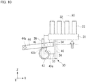
Fig. 10 is a diagram schematically illustrating an example of the state in which thenosepiece support 30 is elevated. InFig. 10 , as inFig. 8 described above, the shape or the arrangement of each component is schematically illustrated and some components are not illustrated.Fig. 10 illustrates the position of thenosepiece support 30 when thecam follower 45 is in contact with thelargest diameter part 43b of thecam 43, as illustrated inFig. 9 . As illustrated inFig. 10 , when thecam follower 45 is in contact with thelargest diameter part 43b of thecam 43, thecontact part 46 attains the highest position as described above. Thedrive force receiver 34 is thus pushed upward by thecontact part 46, whereby thenosepiece support 30 comes into a state of being elevated to the highest position. In such a state, theobjective lens 32 is closest to the stage 50 (specimen). - Even when the
cam 43 is further rotated from the state illustrated inFig. 9 andFig. 10 , thescrew 36a (seeFig. 3 ) reaches the upper end of the slot of thenosepiece receptacle 33, whereby the upward movement of thenosepiece support 30, that is, the upward movement of thelink rod 44 is restricted. As a result, the rotation of thecam 43 beyond thestep 43c is restricted, and therefore thenosepiece support 30 temporarily moved up does not suddenly move down. When thenosepiece support 30 is moved down, thecontact part 46 is moved down by manipulating theoperation knob 14 to rotate thecam 43 in the direction opposite to the direction above (counterclockwise inFig. 9 and clockwise inFig. 10 ). Thenosepiece support 30 moves down under its own weight as thecontact part 46 moves down. - Thus, the
objective lens 32 can be moved along the optical axis AX by manipulating theoperation knob 14. For example, the user manipulates theoperation knob 14 to move theobjective lens 32 while looking through the eyepieces 13 (seeFig. 1 andFig. 2 ) so that theobjective lens 32 can be disposed at a desired focus position for the specimen. When the autofocus 38 (seeFig. 3 andFig. 4 ) is driven, thedriver 40 may be driven based on the detection result of theautofocus 38 to adjust the position of the nosepiece support 30 (objective lens 32). - In the present embodiment, as described above, the
spacer 90 can be mounted on themicroscope apparatus 100 such that thenosepiece support 30 is disposed at a distance from thebase 11. However, even when thespacer 90 is mounted, thedriver 40 is disposed on thepillar 20 and therefore the distance from thedriver 40 to thenosepiece support 30 does not change. That is, in the present embodiment, the distance between the base having the driver thereon and the nosepiece moved by the driver does not increase as in Patent Literature 1. Accordingly, the distance between the base and the nosepiece is the same before and after the spacer is disposed, and the shaking in the lateral direction of the nosepiece relative to the base does not increase. A specimen thus can be observed accurately. - Specifically, for example, in a conventional configuration in which the driver is contained in the
base 11, the driver moves the focusing device up and down, and the nosepiece support having the nosepiece mounted thereon is disposed in the focusing device, the spacer is disposed between the nosepiece support and the focusing device. Such a configuration more largely affects shaking in the XY direction due to vibration and, in addition, may more largely affects deformation by thermal expansion of a component in the transmission path due to a change in the ambient temperature, and there arises a possibility that theobjective lens 32 is displaced in the XY direction. By contrast, in the present embodiment, even when thespacer 90 is not mounted, the distance between the driver 40 (drive source 41) and the nosepiece support 30 (objective lens 32) is smaller than in the conventional configuration, and thedrive source 41, thedriver 40, and thenosepiece support 30 are disposed in the pillarlower part 20b. The up/down movement of thenosepiece 31, which is an objective lens holder, can be thus stabilized. In the present embodiment, even when thespacer 90 is mounted, the positional relation between thedrive source 41 and thenosepiece support 30 does not change, and the effect by deformation of a component due to a change in the ambient temperature does not change before and after thespacer 90 is disposed, so that variations in the position in the XY direction of theobjective lens 32 can be suppressed. In other words, this configuration can prevent a phenomenon in which the focus position of theobjective lens 32 is shifted because of the ambient temperature before and after thespacer 90 is disposed. Accordingly, a specimen can be observed accurately. - For example, in a conventional configuration in which the driver is contained in the
base 11, when thespacer 90 is mounted, a transmission for drive force to thenosepiece support 30 has to be extended by the amount corresponding to thespacer 90, thereby increasing the transmission path of drive force. Consequently, deformation by thermal expansion of a component in the transmission path due to a change in the ambient temperature or the like may be large, and theobjective lens 32 may be displaced. By contrast, in the present embodiment, even when thespacer 90 is mounted, the transmission path of drive force from thedrive source 41 to thenosepiece support 30 is short and therefore deformation of a component due to a change in the ambient temperature is small, which suppresses variation in the position of theobjective lens 32. In other words, a phenomenon in which the focus position of theobjective lens 32 is shifted because of the ambient temperature is less likely to occur. Accordingly, a specimen can be observed accurately. - In the above-noted configuration in which the driver is contained in the
base 11, for example, when thespacer 90 is disposed between thenosepiece support 30 and the transmission, the distance between thenosepiece support 30 and the transmission is long when thespacer 90 is mounted. By contrast, in the present embodiment, even when thespacer 90 is mounted or when thespacer 90 is removed, there is no need for changing the positional relation between the transmission and the nosepiece support, and no additional operation for mounting or removing thespacer 90 is necessary, which facilitates the easy handling by the user. - Although embodiments have been described above, the present invention is not limited to the foregoing description, and various modifications can be made without departing from the spirit of the present invention. The configuration of the present embodiment may be partially omitted. For example, although the
nosepiece support 30 is moved by onedriver 40 in the foregoing embodiment, the present invention is not limited thereto. For example, two ormore drivers 40 may be installed in thenosepiece unit 200. In such a case, two ormore drivers 40 may be controlled simultaneously, or onedriver 40 may be used as a main driver and theother drivers 40 may be used as sub-drivers or backups. - Although the
driver 40 uses thegear train 42 to transmit the drive force of thedrive source 41 to thecam 43 in the foregoing embodiment, the present invention is not limited thereto. For example, the drive force may be transmitted using a belt or a chain. In such a case, a driving pulley or a driving sprocket may be attached to theoutput shaft 41a of thedrive source 41, a driven pulley or a driven sprocket may be attached to thecam 43, and a belt or a chain may be stretched between them. The outer diameter of the pulley or the sprocket is set for each of the driving side and the driven side, whereby the drive force can be transmitted to thecam 43 at a predetermined reduction ratio. - Although the
driver 40 allows thecam 43 to rotate thelink rod 44 and elevate or lower thecontact part 46 in the foregoing embodiment, the present invention is not limited thereto. For example, without the use of thelink rod 44, the cam surface of thecam 43 may directly push thedrive force receiver 34 of thenosepiece support 30 upward. - Although the
driver 40 uses the components such as thegear train 42, thecam 43, and thelink rod 44 to transmit the drive force of thedrive source 41 to thenosepiece support 30 in the foregoing embodiment, the present invention is not limited thereto. For example, the drive force of thedrive source 41 may be transmitted to thenosepiece support 30 using a rack and a pinion gear. For example, theoutput shaft 41a of thedrive source 41 is transmitted to a pinion gear, and the pinion gear is meshed with a rod-like rack movable in the up/down direction. Thedrive source 41 is driven to move the rack in the up/down direction. The upper end of the rack is brought into contact with the lower surface of thedrive force receiver 34 of thenosepiece support 30, whereby thenosepiece support 30 can move up and down as the rack moves up and down. - When a rack and a pinion gear are used as the
driver 40, for example, the rack may be attached to thenosepiece support 30, and thedrive source 41 may be driven to rotate the pinion gear, whereby thenosepiece support 30 integrated with the rack moves up and down. In such a case, thedrive source 41 and the pinion gear may be disposed in thenosepiece support 30, and the rack may be disposed, for example, at theframe 47 of thedriver 40. - AX ... optical axis, 10 ... base unit, 11 ... base, 12 ... tube, 13 ... eyepiece, 14 ... operation knob, 15, 21 ... connector, 20 ... pillar, 20b ... pillar lower part (support), 30 ... nosepiece support, 31 ... nosepiece (objective lens holder), 32 ... objective lens, 33 ... nosepiece receptacle, 34 ... drive force receiver, 36 ... guide, 40 ... driver, 41 ... drive source, 41a ... output shaft, 42 ... gear train, 43 ... cam, 43a ... smallest diameter part, 43b ... largest diameter part, 43c ... step part, 44 ... link rod, 44a ... shaft, 45 ... cam follower, 46 ... contact part, 47 ... frame, 49 ... pin, 50 ... stage, 60 ... first illumination system (illumination apparatus), 70 ... second illumination system (illumination apparatus), 72, 82 ... mirror, 80 ... third illumination system (illumination apparatus), 82a ... optical unit, 90 ... spacer, 91 ... pillar spacer, 92 ... stage spacer, 93 ... base-side connector, 94 ... pillar-side connector, 100 ... microscope apparatus, 200 ... nosepiece unit (objective lens unit)
Claims (11)
- A microscope apparatus comprising:a base;a support disposed upright on the base; andan objective lens unit supported by the support and including an objective lens holder that holds an objective lens, whereinthe objective lens unit includes a drive source that moves the objective lens holder up and down and a driver that transmits a drive force of the drive source to the objective lens holder.
- The microscope apparatus according to claim 1, wherein the support further supports a stage on which a specimen is disposed.
- The microscope apparatus according to claim 1 or 2, wherein the support is a part of an illumination pillar including an illumination apparatus or is a member that supports an illumination pillar.
- The microscope apparatus according to any one of claims 1 to 3, wherein the base and the objective lens unit are separable.
- The microscope apparatus according to any one of claims 1 to 4, wherein
the base and the objective lens unit are separable,
the microscope apparatus comprises a spacer optionally disposed between the base and the objective lens unit in a state in which the base and the objective lens unit are separated, and
the objective lens unit is disposed on the base with the spacer interposed therebetween. - The microscope apparatus according to claim 5, wherein the spacer includes a connector that electrically connects the base with the objective lens unit in a state in which the objective lens unit is disposed on the base with the spacer interposed therebetween.
- The microscope apparatus according to claim 6, wherein the base has a connector disposed on an upper surface of the base on a back side with respect to an observer side.
- The microscope apparatus according to any one of claims 1 to 7, wherein an optical unit is optionally disposed between the base and the objective lens unit in a state in which the support is disposed on the base with the spacer interposed therebetween.
- The microscope apparatus according to any one of claims 1 to 8, wherein the microscope apparatus is an inverted microscope.
- An objective lens unit comprising:an attachment and detachment mechanism that is attachable to and detachable from a base of a microscope apparatus;an objective lens holder on which an objective lens is mounted;a drive source that moves the objective lens holder up and down; anda driver that transmits a drive force of the drive source to the objective lens holder, whereinthe objective lens unit is mounted to a support disposed upright on the base.
- The objective lens unit according to claim 10, wherein the driver includes a guide that guides movement of the objective lens unit along the support.
Applications Claiming Priority (1)
| Application Number | Priority Date | Filing Date | Title |
|---|---|---|---|
| PCT/JP2016/080619 WO2018070048A1 (en) | 2016-10-14 | 2016-10-14 | Microscope apparatus and objective lens unit |
Publications (2)
| Publication Number | Publication Date |
|---|---|
| EP3528028A1 true EP3528028A1 (en) | 2019-08-21 |
| EP3528028A4 EP3528028A4 (en) | 2020-07-22 |
Family
ID=61905439
Family Applications (1)
| Application Number | Title | Priority Date | Filing Date |
|---|---|---|---|
| EP16918557.6A Pending EP3528028A4 (en) | 2016-10-14 | 2016-10-14 | Microscope apparatus and objective lens unit |
Country Status (4)
| Country | Link |
|---|---|
| US (1) | US11249296B2 (en) |
| EP (1) | EP3528028A4 (en) |
| JP (1) | JP6879310B2 (en) |
| WO (1) | WO2018070048A1 (en) |
Families Citing this family (4)
| Publication number | Priority date | Publication date | Assignee | Title |
|---|---|---|---|---|
| EP3528028A4 (en) | 2016-10-14 | 2020-07-22 | Nikon Corporation | Microscope apparatus and objective lens unit |
| CN110967816B (en) * | 2019-11-06 | 2021-06-15 | 浙江大学 | Near-infrared two-zone wide-field microscopic imaging system based on multi-dimensional adjusting frame |
| CN113640231A (en) * | 2021-09-15 | 2021-11-12 | 重庆医科大学 | High-speed automatic microscopic imaging device |
| CN114509868B (en) * | 2022-01-27 | 2023-05-02 | 宁波大学 | Precise zooming multi-field microscopic imaging device and method |
Family Cites Families (14)
| Publication number | Priority date | Publication date | Assignee | Title |
|---|---|---|---|---|
| NZ203838A (en) * | 1983-04-08 | 1988-02-12 | Donald Rivers Ensor | Inverted microscope |
| US4756611A (en) * | 1984-08-31 | 1988-07-12 | Olympus Optical Co., Ltd. | Multiple-purpose microscope |
| JP2966514B2 (en) * | 1990-11-19 | 1999-10-25 | オリンパス光学工業株式会社 | Microscope with focusing mechanism |
| JPH07120825A (en) * | 1993-10-21 | 1995-05-12 | Olympus Optical Co Ltd | Macro-photographing device |
| JPH1138326A (en) * | 1997-07-17 | 1999-02-12 | Nikon Corp | Inverted microscope |
| JP3885305B2 (en) * | 1997-08-27 | 2007-02-21 | 株式会社ニコン | Inverted microscope |
| JPH11344675A (en) | 1998-05-29 | 1999-12-14 | Nikon Corp | Inverted microscope |
| JP5586326B2 (en) * | 2010-05-28 | 2014-09-10 | オリンパス株式会社 | Inverted microscope |
| JP5969808B2 (en) * | 2012-04-27 | 2016-08-17 | オリンパス株式会社 | Microscope equipment |
| JP2014106291A (en) * | 2012-11-26 | 2014-06-09 | Olympus Corp | Object lens drive mechanism and inverted microscope |
| EP3014328B1 (en) * | 2013-06-28 | 2022-05-25 | Discover Echo Inc. | Upright and inverted microscope |
| JP6411763B2 (en) * | 2013-07-18 | 2018-10-24 | オリンパス株式会社 | Microscope system and objective lens unit |
| JP5804154B2 (en) | 2014-07-14 | 2015-11-04 | 株式会社ニコン | Autofocus optical device, microscope |
| EP3528028A4 (en) | 2016-10-14 | 2020-07-22 | Nikon Corporation | Microscope apparatus and objective lens unit |
-
2016
- 2016-10-14 EP EP16918557.6A patent/EP3528028A4/en active Pending
- 2016-10-14 WO PCT/JP2016/080619 patent/WO2018070048A1/en unknown
- 2016-10-14 JP JP2018544668A patent/JP6879310B2/en active Active
-
2019
- 2019-04-15 US US16/383,809 patent/US11249296B2/en active Active
Also Published As
| Publication number | Publication date |
|---|---|
| JPWO2018070048A1 (en) | 2019-08-08 |
| WO2018070048A1 (en) | 2018-04-19 |
| US11249296B2 (en) | 2022-02-15 |
| US20190243116A1 (en) | 2019-08-08 |
| EP3528028A4 (en) | 2020-07-22 |
| JP6879310B2 (en) | 2021-06-02 |
Similar Documents
| Publication | Publication Date | Title |
|---|---|---|
| US11249296B2 (en) | Microscope apparatus and objective lens unit | |
| JP6411763B2 (en) | Microscope system and objective lens unit | |
| US8053711B2 (en) | System and method for adjusting the spherical aberration of objective lenses | |
| JP5567020B2 (en) | Optical path length sensor and method for optimal absorbance measurement | |
| JP6280770B2 (en) | measuring device | |
| US20190219808A1 (en) | Observation device | |
| US7289265B2 (en) | Microscope illumination intensity measuring device | |
| JP2004302441A (en) | System microscope | |
| US9645345B2 (en) | Optical element alignment and retention for optical instruments | |
| JP4539275B2 (en) | Unit type microscope equipment | |
| US9989748B1 (en) | Upright and inverted microscope | |
| JP2014160209A (en) | Stage device | |
| CN110967821A (en) | Microscope device | |
| US9389407B2 (en) | Microscope system and microscope frame | |
| JP4837349B2 (en) | microscope | |
| JP2018063408A (en) | Vertical motion driving device and microscope device | |
| US10317658B2 (en) | Microscope system and correction collar operating device | |
| JP2014207271A (en) | Monitoring device and component mounting apparatus | |
| JP6247933B2 (en) | Magnifying observation device | |
| JP3125124U (en) | Infrared microscope | |
| JP5581752B2 (en) | Autofocus optical device, microscope | |
| JP2015127775A (en) | Magnifying observation device | |
| US20160282595A1 (en) | Objective lens changer | |
| JP2009098229A (en) | Illumination controller for microscope, illuminating device for microscope, microscope, and program | |
| WO2018070049A1 (en) | Microscope apparatus, image processing method, and processing device |
Legal Events
| Date | Code | Title | Description |
|---|---|---|---|
| STAA | Information on the status of an ep patent application or granted ep patent |
Free format text: STATUS: THE INTERNATIONAL PUBLICATION HAS BEEN MADE |
|
| PUAI | Public reference made under article 153(3) epc to a published international application that has entered the european phase |
Free format text: ORIGINAL CODE: 0009012 |
|
| STAA | Information on the status of an ep patent application or granted ep patent |
Free format text: STATUS: REQUEST FOR EXAMINATION WAS MADE |
|
| 17P | Request for examination filed |
Effective date: 20190423 |
|
| AK | Designated contracting states |
Kind code of ref document: A1 Designated state(s): AL AT BE BG CH CY CZ DE DK EE ES FI FR GB GR HR HU IE IS IT LI LT LU LV MC MK MT NL NO PL PT RO RS SE SI SK SM TR |
|
| AX | Request for extension of the european patent |
Extension state: BA ME |
|
| DAV | Request for validation of the european patent (deleted) | ||
| DAX | Request for extension of the european patent (deleted) | ||
| A4 | Supplementary search report drawn up and despatched |
Effective date: 20200619 |
|
| RIC1 | Information provided on ipc code assigned before grant |
Ipc: G02B 7/16 20060101ALI20200615BHEP Ipc: G02B 21/24 20060101ALI20200615BHEP Ipc: G02B 21/02 20060101ALI20200615BHEP Ipc: G02B 21/00 20060101AFI20200615BHEP Ipc: G02B 7/04 20060101ALI20200615BHEP |
|
| STAA | Information on the status of an ep patent application or granted ep patent |
Free format text: STATUS: EXAMINATION IS IN PROGRESS |
|
| 17Q | First examination report despatched |
Effective date: 20220412 |
|
| P01 | Opt-out of the competence of the unified patent court (upc) registered |
Effective date: 20230517 |