EP3526492B1 - Schaltungsgehäuse zum aufnehmen eines abschnitts eines wählhebels für ein fahrzeug und schaltungsbaugruppe - Google Patents
Schaltungsgehäuse zum aufnehmen eines abschnitts eines wählhebels für ein fahrzeug und schaltungsbaugruppe Download PDFInfo
- Publication number
- EP3526492B1 EP3526492B1 EP17772337.6A EP17772337A EP3526492B1 EP 3526492 B1 EP3526492 B1 EP 3526492B1 EP 17772337 A EP17772337 A EP 17772337A EP 3526492 B1 EP3526492 B1 EP 3526492B1
- Authority
- EP
- European Patent Office
- Prior art keywords
- base
- cover
- latching element
- selector
- selector lever
- Prior art date
- Legal status (The legal status is an assumption and is not a legal conclusion. Google has not performed a legal analysis and makes no representation as to the accuracy of the status listed.)
- Active
Links
Images



Classifications
-
- F—MECHANICAL ENGINEERING; LIGHTING; HEATING; WEAPONS; BLASTING
- F16—ENGINEERING ELEMENTS AND UNITS; GENERAL MEASURES FOR PRODUCING AND MAINTAINING EFFECTIVE FUNCTIONING OF MACHINES OR INSTALLATIONS; THERMAL INSULATION IN GENERAL
- F16H—GEARING
- F16H59/00—Control inputs to control units of change-speed- or reversing-gearings for conveying rotary motion
- F16H59/02—Selector apparatus
- F16H59/0278—Constructional features of the selector lever, e.g. grip parts, mounting or manufacturing
-
- B—PERFORMING OPERATIONS; TRANSPORTING
- B60—VEHICLES IN GENERAL
- B60K—ARRANGEMENT OR MOUNTING OF PROPULSION UNITS OR OF TRANSMISSIONS IN VEHICLES; ARRANGEMENT OR MOUNTING OF PLURAL DIVERSE PRIME-MOVERS IN VEHICLES; AUXILIARY DRIVES FOR VEHICLES; INSTRUMENTATION OR DASHBOARDS FOR VEHICLES; ARRANGEMENTS IN CONNECTION WITH COOLING, AIR INTAKE, GAS EXHAUST OR FUEL SUPPLY OF PROPULSION UNITS IN VEHICLES
- B60K20/00—Arrangement or mounting of change-speed gearing control devices in vehicles
- B60K20/02—Arrangement or mounting of change-speed gearing control devices in vehicles of initiating means
-
- B—PERFORMING OPERATIONS; TRANSPORTING
- B60—VEHICLES IN GENERAL
- B60K—ARRANGEMENT OR MOUNTING OF PROPULSION UNITS OR OF TRANSMISSIONS IN VEHICLES; ARRANGEMENT OR MOUNTING OF PLURAL DIVERSE PRIME-MOVERS IN VEHICLES; AUXILIARY DRIVES FOR VEHICLES; INSTRUMENTATION OR DASHBOARDS FOR VEHICLES; ARRANGEMENTS IN CONNECTION WITH COOLING, AIR INTAKE, GAS EXHAUST OR FUEL SUPPLY OF PROPULSION UNITS IN VEHICLES
- B60K20/00—Arrangement or mounting of change-speed gearing control devices in vehicles
- B60K20/02—Arrangement or mounting of change-speed gearing control devices in vehicles of initiating means
- B60K20/08—Dashboard means
-
- F—MECHANICAL ENGINEERING; LIGHTING; HEATING; WEAPONS; BLASTING
- F16—ENGINEERING ELEMENTS AND UNITS; GENERAL MEASURES FOR PRODUCING AND MAINTAINING EFFECTIVE FUNCTIONING OF MACHINES OR INSTALLATIONS; THERMAL INSULATION IN GENERAL
- F16H—GEARING
- F16H59/00—Control inputs to control units of change-speed- or reversing-gearings for conveying rotary motion
- F16H59/02—Selector apparatus
-
- F—MECHANICAL ENGINEERING; LIGHTING; HEATING; WEAPONS; BLASTING
- F16—ENGINEERING ELEMENTS AND UNITS; GENERAL MEASURES FOR PRODUCING AND MAINTAINING EFFECTIVE FUNCTIONING OF MACHINES OR INSTALLATIONS; THERMAL INSULATION IN GENERAL
- F16H—GEARING
- F16H59/00—Control inputs to control units of change-speed- or reversing-gearings for conveying rotary motion
- F16H59/02—Selector apparatus
- F16H2059/026—Details or special features of the selector casing or lever support
Definitions
- the present invention relates to a circuit housing for receiving a portion of a selector lever for a vehicle and a circuit assembly.
- the housing parts of a circuit housing for a vehicle can usually be screwed together.
- circuit housings with locking elements can be found in the documents EP-A1-0279087 or WO-A1-2015 / 152566 or JP-A-09159396 forth.
- circuit housing according to claim 1 and a circuit assembly according to claim 7.
- the circuit housing can be a housing for accommodating a shifting link electronically or mechanically coupled to a vehicle transmission act to shift the vehicle transmission.
- the shifting gate can alternatively be provided for selecting a program for controlling the vehicle, for example for controlling a drive of the vehicle.
- an end portion of the selector lever can be movably mounted in the shifting gate or in the cover part.
- the shift gate can be a suitable mechanism or sensor system for detecting a position or have movement of the selector lever.
- the circuit housing can be screwed to a vehicle console, for example.
- the circuit housing can be a multi-part molded plastic part.
- a base part can be understood as a shell-shaped part of the circuit housing.
- the base part can, for example, be shaped to accommodate the shifting gate.
- a cover part can be understood to mean, for example, a plate-shaped or also bowl-shaped part for covering the base part.
- a floor locking element and a cover locking element can be understood to mean elements which can be locked together without the aid of tools.
- the base latching element and the cover latching element can be locked to one another in a force-locking or positive-locking manner or both in a force-locking and positive-locking manner.
- one of the two locking elements can be designed as an eyelet and another of the two locking elements as a locking lug.
- the approach described here is based on the knowledge that the housing parts of a multi-part shift housing for a vehicle transmission can be locked together without screws using corresponding locking elements. This has the advantage that the circuit housing can be assembled without screws and corresponding tools, which means that the assembly time can be shortened and the production costs can be reduced.
- the cover latching element can be shaped as an eyelet.
- the floor latching element can be designed as a latching lug that can be hooked onto the eyelet.
- An eyelet can be understood to mean, for example, a U-shaped bracket with two legs and a cross strut connecting the two legs to one another.
- the cross strut can act as a stop for the floor locking element.
- the cover latching element can protrude from the cover part in the form of the eyelet.
- the cover latching element can protrude from the cover part perpendicular to a main plane of extent of the cover part. This embodiment can ensure a robust latching between the lid and bottom part.
- the bottom locking element can conversely be formed as an eyelet.
- the cover locking element can be designed as a locking lug that can be hooked onto the eyelet. This embodiment can also ensure a robust latching between the lid and bottom part.
- cover latching element projects from the cover part transversely, for example perpendicularly to a main plane of extent of the cover part.
- the floor locking element can protrude from the floor part transversely, for example perpendicularly to a main extension plane of the floor part.
- a main extension plane can be understood to mean a plane of the greatest extent of the cover part or of the base part. This can simplify the joining of the lid and base part.
- the base part can have at least one additional base locking element.
- the cover part can have at least one further cover locking element which can be locked with the further floor locking element. As a result, the cover part can be securely attached to the bottom part.
- the bottom part can be rectangular, for example. Additionally or alternatively, the cover part can also be rectangular.
- the floor latching element and the further floor latching element can be arranged on opposite sides of the floor part. Accordingly, the cover locking element and the further cover locking element can be arranged on opposite sides of the cover part. As a result, the cover part can be latched to the base part in a particularly simple manner using only two pairs of latching elements.
- the base part has at least one base projection with an insertion opening for inserting a screw.
- the cover part also has at least one cover projection with a push-through opening for pushing the screw through.
- the push-through opening is located here of the bottom protrusion and the push-through opening of the lid protrusion face each other when the lid part is attached to the bottom part.
- the base part can also have a plurality of base projections, for example at least four base projections.
- the cover part can have as many cover protrusions as the base part has base protrusions.
- the base or cover projections can each be arranged adjacent to a corner of the base or cover part. This embodiment enables the circuit housing to be screwed into the vehicle with the smallest possible number of screws. This reduces the assembly effort.
- the base projection is designed as a stop for mounting the circuit housing in a vehicle console. This further simplifies the assembly of the circuit housing.
- the cover part can have a selector lever opening for guiding the selector lever through.
- the selector lever can be inserted very easily into the circuit housing, for example even after the circuit housing has been installed in the vehicle.
- the base part or, additionally or alternatively, the cover part is designed as a molded plastic part.
- the circuit housing can be produced in a wide variety of forms at relatively low manufacturing costs.
- circuit assembly offers the advantage of particularly simple and quick installation.
- the circuit assembly can be used to control various functions in the vehicle.
- the circuit assembly can be used to shift a vehicle transmission or to control a drive or an information system of the vehicle.
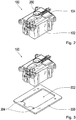
- FIG. 1 shows a schematic representation of a circuit housing 100 according to an embodiment, here in the disassembled state.
- the circuit housing 100 comprises a shell-shaped base part 102 and a plate-shaped cover part 104 for closing the base part 102.
- the base part 102 is formed with a base locking element 106 and a further base locking element 108.
- the base part 102 is, for example, rectangular in shape, the two base locking elements 106, 108 each being arranged centrally on a narrow side of the base part 102 and thus lying opposite one another.
- the cover part 104 has a cover latching element 110 which can be latched to the floor latching element 106 and a further lid latching element 112 which can be latched to the further floor latching element 108. Similar to the base part 102, the cover part 104 is also rectangular, the two cover latching elements 110, 112 also being arranged centrally on a narrow side of the cover part 104. By means of the four latching elements 106, 108, 110, 112, the cover part 102 can be fastened to the base part 104 without screws.
- the base part 102 can have more than two base locking elements and the cover part 104 can have more than two cover locking elements.
- the two cover latching elements 110, 112 are each designed as a U-shaped clamp or eyelet with two legs 114 and a cross strut 116 connecting the two legs 114 to one another.
- the two cover latching elements 110, 112 each protrude from the cover part 104 essentially perpendicularly to a main plane of extent of the cover part 104 in an assembly direction.
- the mounting direction is marked with a vertical arrow.
- the two floor latching elements 106, 108 are each formed as a latching lug which is hooked to the cross strut 116 in the assembled state of the circuit housing 100.
- the latching lug is designed, for example, as a tab which is elastically connected to a side wall of the base part 102 and which projects slightly obliquely from the side wall when not loaded.
- the bottom latching elements 106, 108 are formed in the form of a clip or eyelet, while the lid latching elements 110, 112 are shaped as a latching lug.
- the base part 102 realized with four floor projections 118.
- the four base projections 118 each have a push-through opening 120 for pushing a screw through.
- the four base projections 118 are each arranged on a corner of the base part 102 facing the cover part 104.
- the cover part 104 also has four cover projections 122, each with a push-through opening 124 for pushing a screw through.
- the cover projections 122 are arranged on the cover part 104 in such a way that in the assembled state of the circuit housing 100, one of the cover projections 122 lies flat on each of the bottom projections 120, the respective push-through openings 120, 124 lying congruently one above the other, that is to say flush with one another.
- Figure 2 shows a schematic representation of a circuit housing 100 from Figure 1 in the assembled state.
- the cover part 104 according to this exemplary embodiment is realized with a selector lever opening 200 for passing a section of a selector lever, for example a gear selector lever or a program selector lever.
- the selector lever can be provided to be operated by a driver of a vehicle.
- the selector lever opening 200 is placed essentially centrally on the cover part 104.
- FIG. 3 shows a schematic representation of a circuit housing 100 from FIG. 2 and a vehicle console 300.
- the vehicle console 300 is, for example, part of a vehicle in which the circuit housing 100 is to be mounted.
- the vehicle console 300 implemented here as a simple plate, comprises a cutout 302 for the circuit housing 100 and, by way of example, four screw holes 304 for inserting or screwing in one screw each.
- Figure 4 shows a schematic representation of a circuit housing 100 from FIG. 2 and a vehicle console 300.
- Figure 3 shows Figure 4 the circuit housing 100 and the vehicle console 300 in the assembled state.
- the Circuit housing 100 is partially passed through the cutout, the bottom projections 118 of the bottom part 102 functioning as stops and the respective push-through openings of the bottom projections 118 and the lid projections 122 being congruent with the screw holes in the vehicle console 300.
- FIG. 5 shows a schematic representation of a circuit housing 100 from FIG. 2 and a vehicle console 300.
- the circuit housing 100 and the vehicle console 300 in Figure 5 shown in the assembled state.
- four screws 500 for screwing the circuit housing 100 to the vehicle console 300 by means of the projections 118, 122 are shown.
- the housing parts 102, 104 are only finally joined together when the circuit housing 100 is installed in the vehicle using the screws 500.
- FIG. 6 shows a schematic representation of a circuit assembly 600 according to an embodiment.
- the circuit assembly 600 comprises the circuit housing 100, for example a circuit housing, as previously described with reference to FIG Figures 1 to 5 is described, a selector lever 602, which is inserted through the selector lever opening 200 of the cover part 104 into the circuit housing 100, and a shifting gate 604 arranged in the bottom part 102.
- the shifting gate 604 can be a shifting gate 604 mechanically actuated by the selector lever 602 or are a shift gate 604 which is designed to electronically detect a position or movement of the selector lever 602 using a suitable sensor system and to provide an actuating signal representing the position or movement.
- an end section of the selector lever 602 is movably arranged in the shifting gate 604.
- the selector lever 602 is used to select a transmission position of the vehicle transmission, which can in particular be an automatic transmission, or for example to select a driving program of the vehicle.
- the selector lever 602 is rotatably or pivotably mounted on the selector lever opening 200.
- an exemplary embodiment includes a "and / or" link between a first feature and a second feature, this can be read in such a way that the Embodiment according to one embodiment has both the first feature and the second feature and according to a further embodiment either only the first feature or only the second feature.
Landscapes
- Engineering & Computer Science (AREA)
- Mechanical Engineering (AREA)
- General Engineering & Computer Science (AREA)
- Chemical & Material Sciences (AREA)
- Combustion & Propulsion (AREA)
- Transportation (AREA)
- Arrangement Or Mounting Of Control Devices For Change-Speed Gearing (AREA)
- Switch Cases, Indication, And Locking (AREA)
Description
- Die vorliegende Erfindung bezieht sich auf ein Schaltungsgehäuse zum Aufnehmen eines Abschnitts eines Wählhebels für ein Fahrzeug und auf eine Schaltungsbaugruppe.
- Die Gehäuseteile eines Schaltungsgehäuses für ein Fahrzeug sind in der Regel miteinander verschraubbar.
- Aus dem Dokument
DE-A1-10 2007 005 496 ist ein Schaltungsgehäuse mit einem Bodenteil und einem Deckelteil bekannt, welche miteinander verrastet sind. - Weitere Schaltungsgehäuse mit Verrastungselementen gehen aus den Dokumenten
EP-A1-0279087 oderWO-A1-2015/152566 oderJP-A-09159396 - Es ist Aufgabe der Erfindung ein verbessertes Schalgungsgehäuse wie auch eine verbesserte Schaltungsbaugruppe zu schaffen, speziell um damit den Montageaufwand zu reduzieren.
- Die Aufgabe wird durch ein Schaltungsgehäuse gemäß Anspruch 1 und einer Schaltungsbaugruppe gemäß Anspruch 7 gelöst.
- Vorteilhafte Weiterbildungen der Erfindung ergeben sich aus den abhängigen Ansprüchen.
- Bei dem Schaltungsgehäuse kann es sich um ein Gehäuse zum Aufnehmen einer elektronisch oder mechanisch mit einem Fahrzeuggetriebe gekoppelten Schaltkulisse zum Schalten des Fahrzeuggetriebes handeln. Wenn es sich bei dem Wählhebel um einen Programmwählhebel handelt, kann die Schaltkulisse alternativ zum Auswählen eines Programms zum Steuern des Fahrzeugs, beispielsweise zum Steuern eines Antriebs des Fahrzeugs, vorgesehen sein. Hierbei kann ein Endabschnitt des Wählhebels beweglich in der Schaltkulisse oder auch im Deckelteil gelagert sein. Die Schaltkulisse kann eine geeignete Mechanik oder Sensorik zum Erfassen einer Stellung oder Bewegung des Wählhebels aufweisen. Das Schaltungsgehäuse kann beispielsweise mit einer Fahrzeugkonsole verschraubbar sein. Insbesondere kann es sich bei dem Schaltungsgehäuse um ein mehrteiliges Kunststoffformteil handeln. Unter einem Bodenteil kann ein schalenförmiges Teil des Schaltungsgehäuses verstanden werden. Das Bodenteil kann beispielsweise ausgeformt sein, um die Schaltkulisse aufzunehmen. Unter einem Deckelteil kann beispielsweise ein platten- oder ebenfalls schalenförmiges Teil zum Abdecken des Bodenteils verstanden werden. Unter einem Bodenverrastungselement und einem Deckelverrastungselement können Elemente verstanden werden, die ohne Zuhilfenahme von Werkzeug miteinander verrastbar sind. Im montierten Zustand des Schaltungsgehäuses können das Bodenverrastungselement und das Deckelverrastungselement kraft- oder formschlüssig oder sowohl kraft- als auch formschlüssig miteinander verrastet sein. Beispielsweise kann eines der beiden Verrastungselemente als Öse und ein anderes der beiden Verrastungselemente als Rastnase ausgeformt sein.
- Der hier beschriebene Ansatz beruht auf der Erkenntnis, dass die Gehäuseteile eines mehrteiligen Schaltungsgehäuses für ein Fahrzeuggetriebe mithilfe entsprechender Verrastungselemente schraubenlos miteinander verrastet werden können. Dies hat den Vorteil, dass das Schaltungsgehäuse ohne Schrauben und entsprechendes Werkzeug zusammengefügt werden kann, womit die Montagezeit verkürzt werden kann und die Herstellungskosten reduziert werden können.
- Gemäß einer Ausführungsform kann das Deckelverrastungselement als Öse ausgeformt sein. Das Bodenverrastungselement kann als eine mit der Öse verhakbare Rastnase ausgeformt sein. Unter einer Öse kann beispielsweise eine U-förmige Klammer mit zwei Schenkeln und einer die beiden Schenkel miteinander verbindenden Querstrebe verstanden werden. Dabei kann die Querstrebe als Anschlag für das Bodenverrastungselement fungieren. Beispielsweise kann das Deckelverrastungselement in Form der Öse von dem Deckelteil abragen. Insbesondere kann das Deckelverrastungselement dabei senkrecht zu einer Haupterstreckungsebene des Deckelteils von dem Deckelteil abragen. Durch diese Ausführungsform kann eine robuste Verrastung zwischen Deckel- und Bodenteil gewährleistet werden.
- Gemäß einer weiteren Ausführungsform kann umgekehrt das Bodenverrastungselement als Öse ausgeformt sein. Dabei kann das Deckelverrastungselement als eine mit der Öse verhakbare Rastnase ausgeformt sein. Auch durch diese Ausführungsform kann eine robuste Verrastung zwischen Deckel- und Bodenteil gewährleistet werden.
- Es ist ferner vorteilhaft, wenn das Deckelverrastungselement quer, beispielsweise senkrecht zu einer Haupterstreckungsebene des Deckelteils von dem Deckelteil abragt. Zusätzlich oder alternativ kann das Bodenverrastungselement quer, beispielsweise senkrecht zu einer Haupterstreckungsebene des Bodenteils von dem Bodenteil abragen. Unter einer Hauptstreckungsebene kann eine Ebene der größten Ausdehnung des Deckelteils bzw. des Bodenteils verstanden werden. Dadurch kann das Zusammenfügen von Deckel- und Bodenteil vereinfacht werden.
- Das Bodenteil kann gemäß einer weiteren Ausführungsform zumindest ein weiteres Bodenverrastungselement aufweisen. Dabei kann das Deckelteil zumindest ein mit dem weiteren Bodenverrastungselement verrastbares weiteres Deckelverrastungselement aufweisen. Dadurch kann das Deckelteil sicher an dem Bodenteil befestigt werden.
- Das Bodenteil kann beispielsweise rechteckig ausgeformt sein. Zusätzlich oder alternativ kann auch das Deckelteil rechteckig ausgeformt sein. Dabei können das Bodenverrastungselement und das weitere Bodenverrastungselement an einander gegenüberliegenden Seiten des Bodenteils angeordnet sein. Entsprechend können das Deckelverrastungselement und das weitere Deckelverrastungselement an einander gegenüberliegenden Seiten des Deckelteils angeordnet sein. Dadurch kann das Deckelteil mithilfe lediglich zweier Paare von Verrastungselementen und somit besonders einfach mit dem Bodenteil verrastet werden.
- Erfindungsgemäß weist das Bodenteil zumindest einen Bodenvorsprung mit einer Durchstecköffnung zum Durchstecken einer Schraube auf. Das Deckelteil weist ferner zumindest einen Deckelvorsprung mit einer Durchstecköffnung zum Durchstecken der Schraube auf. Dabei liegen die Durchstecköffnung des Bodenvorsprungs und die Durchstecköffnung des Deckelvorsprungs einander gegenüber, wenn das Deckelteil an dem Bodenteil befestigt ist. Je nach Ausführungsform kann das Bodenteil auch eine Mehrzahl von Bodenvorsprüngen, beispielsweise zumindest vier Bodenvorsprünge, aufweisen. Entsprechend kann das Deckelteil so viele Deckelvorsprünge aufweisen, wie das Bodenteil Bodenvorsprünge aufweist. Beispielsweise können die Boden- oder Deckelvorsprünge je benachbart zu je einer Ecke des Boden- bzw. Deckelteils angeordnet sein. Durch diese Ausführungsform wird eine Verschraubung des Schaltungsgehäuses im Fahrzeug mit einer geringstmöglichen Anzahl an Schrauben ermöglicht. Dadurch wird der Montageaufwand reduziert.
- Erfindungsgemäß ist der Bodenvorsprung als Anschlag zur Montage des Schaltungsgehäuses in einer Fahrzeugkonsole ausgebildet . Dadurch wird die Montage des Schaltungsgehäuses weiter vereinfacht.
- Gemäß einer weiteren Ausführungsform kann das Deckelteil eine Wählhebelöffnung zum Hindurchführen des Wählhebels aufweisen. Dadurch kann der Wählhebel sehr einfach in das Schaltungsgehäuse eingeführt werden, etwa auch nach der Montage des Schaltungsgehäuses im Fahrzeug.
- Ferner ist es vorteilhaft, wenn das Bodenteil oder, zusätzlich oder alternativ, das Deckelteil als Kunststoffformteil ausgebildet ist. Dadurch kann das Schaltungsgehäuse in unterschiedlichsten Formen bei verhältnismäßig geringen Fertigungskosten hergestellt werden.
- Der hier vorgestellte Ansatz schafft schließlich eine Schaltungsbaugruppe mit folgenden Merkmalen:
- einem Wählhebel;
- einer Schaltkulisse; und
- einem Schaltungsgehäuse gemäß einer vorstehenden Ausführungsform, wobei die Schaltkulisse in dem Bodenteil angeordnet ist, ein Abschnitt des Wählhebels durch die Wählhebelöffnung des Deckelteils hindurchgeführt ist und ein Endabschnitt des Wählhebels beweglich in der Schaltkulisse angeordnet ist.
- Eine derartige Schaltungsbaugruppe bietet den Vorteil einer besonders einfachen und schnellen Montage. Die Schaltungsbaugruppe kann zum Steuern unterschiedlicher Funktionen im Fahrzeug eingesetzt werden. Beispielsweise kann die Schaltungsbaugruppe zum Schalten eines Fahrzeuggetriebes oder zum Steuern eines Antriebs oder eines Informationssystems des Fahrzeugs verwendet werden.
- Die Erfindung wird anhand der beigefügten Zeichnungen beispielhaft näher erläutert. Es zeigen:
- Figur 1
- eine schematische Darstellung eines Schaltungsgehäuses gemäß einem Ausführungsbeispiel;
- Figur 2
- eine schematische Darstellung eines Schaltungsgehäuses aus
Figur 1 im montierten Zustand; - Figur 3
- eine schematische Darstellung eines Schaltungsgehäuses aus
Figur 2 und einer Fahrzeugkonsole; - Figur 4
- eine schematische Darstellung eines Schaltungsgehäuses aus
Figur 2 und einer Fahrzeugkonsole; - Figur 5
- eine schematische Darstellung eines Schaltungsgehäuses aus
Figur 2 und einer Fahrzeugkonsole; und - Figur 6
- eine schematische Darstellung einer Schaltungsbaugruppe gemäß einem Ausführungsbeispiel.
- In der nachfolgenden Beschreibung bevorzugter Ausführungsbeispiele der vorliegenden Erfindung werden für die in den verschiedenen Figuren dargestellten und ähnlich wirkenden Elemente gleiche oder ähnliche Bezugszeichen verwendet, wobei auf eine wiederholte Beschreibung dieser Elemente verzichtet wird.
-
Figur 1 zeigt eine schematische Darstellung eines Schaltungsgehäuses 100 gemäß einem Ausführungsbeispiel, hier im demontierten Zustand. Das Schaltungsgehäuse 100 umfasst ein schalenförmiges Bodenteil 102 und ein plattenförmiges Deckelteil 104 zum Verschließen des Bodenteils 102. Das Bodenteil 102 ist gemäß diesem Ausführungsbeispiel mit einem Bodenverrastungselement 106 und einem weiteren Bodenverrastungselement 108 ausgebildet. Das Bodenteil 102 ist beispielhaft rechteckig ausgeformt, wobei die beiden Bodenverrastungselemente 106, 108 je mittig an einer Schmalseite des Bodenteils 102 angeordnet sind und somit einander gegenüberliegen. Analog dazu weist das Deckelteil 104 ein mit dem Bodenverrastungselement 106 verrastbares Deckelverrastungselement 110 sowie ein mit dem weiteren Bodenverrastungselement 108 verrastbares weiteres Deckelverrastungselement 112 auf. Ähnlich wie das Bodenteil 102 ist auch das Deckelteil 104 rechteckförmig ausgestaltet, wobei die beiden Deckelverrastungselemente 110, 112 ebenfalls mittig an je einer Schmalseite des Deckelteils 104 angeordnet sind. Mittels der vier Verrastungselemente 106, 108, 110, 112 kann das Deckelteil 102 schraubenlos an dem Bodenteil 104 befestigt werden. - Je nach Ausführungsbeispiel kann das Bodenteil 102 mehr als zwei Bodenverrastungselemente und das Deckelteil 104 mehr als zwei Deckelverrastungselemente aufweisen.
- Gemäß dem in
Figur 1 gezeigten Ausführungsbeispiel sind die beiden Deckelverrastungselemente 110, 112 je als eine U-förmige Klammer oder Öse mit zwei Schenkeln 114 und einer die beiden Schenkel 114 miteinander verbindenden Querstrebe 116 ausgebildet. Dabei ragen die beiden Deckelverrastungselemente 110, 112 je im Wesentlichen senkrecht zu einer Haupterstreckungsebene des Deckelteils 104 in einer Montagerichtung von dem Deckelteil 104 ab. Die Montagerichtung ist mit einem vertikalen Pfeil gekennzeichnet. Die beiden Bodenverrastungselemente 106, 108 sind je als eine Rastnase ausgeformt, die im montierten Zustand des Schaltungsgehäuses 100 mit der Querstrebe 116 verhakt ist. Die Rastnase ist beispielsweise als eine elastisch mit einer Seitenwand des Bodenteils 102 verbundene und im unbelasteten Zustand leicht schräg von der Seitenwand abstehende Lasche ausgebildet. - Gemäß einem alternativen Ausführungsbeispiel sind umgekehrt die Bodenverrastungselemente 106, 108 als Klammer oder Öse ausgeformt, während die Deckelverrastungselemente 110, 112 als Rastnase ausgeformt sind.
- Beispielhaft ist das Bodenteil 102 gemäß
Figur 1 mit vier Bodenvorsprüngen 118 realisiert. Die vier Bodenvorsprüngen 118 weisen je eine Durchstecköffnung 120 zum Durchstecken einer Schraube auf. GemäßFigur 1 sind die vier Bodenvorsprünge 118 je an einer dem Deckelteil 104 zugewandten Ecke des Bodenteils 102 angeordnet. Analog dazu weist auch das Deckelteil 104 vier Deckelvorsprünge 122 mit je einer Durchstecköffnung 124 zum Durchstecken einer Schraube auf. Die Deckelvorsprünge 122 sind derart an dem Deckelteil 104 angeordnet, dass im montierten Zustand des Schaltungsgehäuses 100 je einer der Deckelvorsprünge 122 flächig auf je einem der Bodenvorsprünge 120 aufliegt, wobei die jeweiligen Durchstecköffnungen 120, 124 deckungsgleich übereinanderliegen, also miteinander fluchten. -
Figur 2 zeigt eine schematische Darstellung eines Schaltungsgehäuses 100 aus Figur 1 im montierten Zustand. Wie ausFigur 2 ersichtlich, ist das Deckelteil 104 gemäß diesem Ausführungsbeispiel mit einer Wählhebelöffnung 200 zum Hindurchführen eines Abschnitts eines Wählhebels, beispielsweise eines Gangwählhebels oder eines Programmwählhebels, realisiert. Der Wählhebel kann vorgesehen zu sein, um von einem Fahrer eines Fahrzeugs betätigt zu werden. Beispielhaft ist die Wählhebelöffnung 200 im Wesentlichen mittig an dem Deckelteil 104 platziert. -
Figur 3 zeigt eine schematische Darstellung eines Schaltungsgehäuses 100 aus Figur 2 und einer Fahrzeugkonsole 300. Die Fahrzeugkonsole 300 ist beispielsweise Teil eines Fahrzeugs, in dem das Schaltungsgehäuse 100 montiert werden soll. Die Fahrzeugkonsole 300, hier als einfache Platte realisiert, umfasst eine Aussparung 302 für das Schaltungsgehäuse 100 und beispielhaft vier Schraubenlöcher 304 zum Durchstecken oder Einschrauben je einer Schraube. -
Figur 4 zeigt eine schematische Darstellung eines Schaltungsgehäuses 100 aus Figur 2 und einer Fahrzeugkonsole 300. Im Unterschied zuFigur 3 zeigtFigur 4 das Schaltungsgehäuse 100 und die Fahrzeugkonsole 300 im montierten Zustand. Das Schaltungsgehäuse 100 ist teilweise durch die Aussparung hindurchgeführt, wobei die Bodenvorsprünge 118 des Bodenteils 102 als Anschläge fungieren und die jeweiligen Durchstecköffnungen der Bodenvorsprünge 118 und der Deckelvorsprünge 122 deckungsgleich mit den Schraubenlöchern in der Fahrzeugkonsole 300 sind. -
Figur 5 zeigt eine schematische Darstellung eines Schaltungsgehäuses 100 aus Figur 2 und einer Fahrzeugkonsole 300. Wie inFigur 4 sind das Schaltungsgehäuse 100 und die Fahrzeugkonsole 300 inFigur 5 im montierten Zustand gezeigt. Zusätzlich sind vier Schrauben 500 zum Verschrauben des Schaltungsgehäuses 100 mit der Fahrzeugkonsole 300 mittels der Vorsprünge 118, 122 eingezeichnet. Beispielsweise werden die Gehäuseteile 102, 104 erst bei Montage des Schaltungsgehäuses 100 im Fahrzeug mithilfe der Schrauben 500 endgültig zusammengefügt. -
Figur 6 zeigt eine schematische Darstellung einer Schaltungsbaugruppe 600 gemäß einem Ausführungsbeispiel. Die Schaltungsbaugruppe 600 umfasst das Schaltungsgehäuse 100, etwa ein Schaltungsgehäuse, wie es vorangehend anhand derFiguren 1 bis 5 beschrieben ist, einen Wählhebel 602, der durch die Wählhebelöffnung 200 des Deckelteils 104 in das Schaltungsgehäuse 100 eingeführt ist, sowie eine im Bodenteil 102 angeordnete Schaltkulisse 604. Bei der Schaltkulisse 604 kann es sich um eine durch den Wählhebels 602 mechanisch betätigbare Schaltkulisse 604 handeln oder um eine Schaltkulisse 604 handeln, die ausgebildet ist, um eine Stellung oder Bewegung des Wählhebels 602 elektronisch unter Verwendung einer geeigneten Sensorik zu erfassen und ein die Stellung oder Bewegung repräsentierendes Stellsignal bereitzugeben. Dazu ist ein Endabschnitt des Wählhebels 602 beweglich in der Schaltkulisse 604 angeordnet. Der Wählhebel 602 dient gemäß einem Ausführungsbeispiel zum Wählen einer Getriebestellung des Fahrzeuggetriebes, bei dem es sich insbesondere um ein Automatikgetriebe handeln kann, oder beispielsweise zum Wählen eines Fahrprogramms des Fahrzeugs. Gemäß einem Ausführungsbeispiel ist der Wählhebel 602 an der Wählhebelöffnung 200 dreh- oder schwenkbar gelagert. - Umfasst ein Ausführungsbeispiel eine "und/oder" Verknüpfung zwischen einem ersten Merkmal und einem zweiten Merkmal, so kann dies so gelesen werden, dass das Ausführungsbeispiel gemäß einer Ausführungsform sowohl das erste Merkmal als auch das zweite Merkmal und gemäß einer weiteren Ausführungsform entweder nur das erste Merkmal oder nur das zweite Merkmal aufweist.
-
- 100
- Schaltungsgehäuse
- 102
- Bodenteil
- 104
- Deckelteil
- 106
- Bodenverrastungselement
- 108
- weiteres Bodenverrastungselement
- 110
- Deckelverrastungselement
- 112
- weiteres Deckelverrastungselement
- 114
- Schenkel
- 116
- Querstrebe
- 118
- Bodenvorsprung
- 120
- Durchstecköffnung eines Bodenvorsprungs
- 122
- Durchstecköffnung eines Deckelvorsprungs
- 124
- Deckelvorsprung
- 200
- Wählhebelöffnung
- 300
- Fahrzeugkonsole
- 302
- Aussparung
- 304
- Schraubenloch
- 500
- Schraube
- 600
- Schaltungsbaugruppe
- 602
- Wählhebel
- 604
- Schaltkulisse
Claims (8)
- Schaltungsgehäuse (100) zum Aufnehmen eines Abschnitts eines Wählhebels (602) für ein Fahrzeug, wobei das Schaltungsgehäuse (100) folgende Merkmale aufweist:ein Bodenteil (102) mit zumindest einem Bodenverrastungselement (106); undein Deckelteil (104) zum Verschließen des Bodenteils (102), wobei das Deckelteil (104) zumindest ein mit dem Bodenverrastungselement (106) verrastbares Deckelverrastungselement (110) aufweist, um das Deckelteil (104) schraubenlos an dem Bodenteil (102) befestigen zu können,dadurch gekennzeichnet, dassdas Bodenteil (102) zumindest einen Bodenvorsprung (118) mit einer Durchstecköffnung (120) zum Durchstecken einer Schraube (500) aufweist und das Deckelteil (104) zumindest einen Deckelvorsprung (122) mit einer Durchstecköffnung (124) zum Durchstecken der Schraube (500) aufweist, wobei die Durchstecköffnung (120) des Bodenvorsprungs (118) und die Durchstecköffnung (124) des Deckelvorsprungs (122) einander gegenüberliegen, wenn das Deckelteil (104) an dem Bodenteil (102) befestigt ist, und wobei der Bodenvorsprung (118) als Anschlag zur Montage des Schaltungsgehäuses (100) in einer Fahrzeugkonsole (300) ausgebildet ist.
- Schaltungsgehäuse (100) gemäß Anspruch 1, bei dem das Deckelverrastungselement (110) als Öse ausgeformt und das Bodenverrastungselement (106) als eine mit der Öse verhakbare Rastnase ausgeformt ist, oder bei dem das Bodenverrastungselement (106) als Öse ausgeformt und das Deckelverrastungselement (110) als eine mit der Öse verhakbare Rastnase ausgeformt ist.
- Schaltungsgehäuse (100) gemäß einem der vorangegangenen Ansprüche, bei dem das Deckelverrastungselement (110) quer zu einer Haupterstreckungsebene des Deckelteils (104) von dem Deckelteil (104) abragt oder bei dem das Bodenverrastungselement (106) quer zu einer Haupterstreckungsebene des Bodenteils (102) von dem Bodenteil (102) abragt.
- Schaltungsgehäuse (100) gemäß einem der vorangegangenen Ansprüche, bei dem das Bodenteil (102) zumindest ein weiteres Bodenverrastungselement (108) aufweist und das Deckelteil (104) zumindest ein mit dem weiteren Bodenverrastungselement (108) verrastbares weiteres Deckelverrastungselement (112) aufweist.
- Schaltungsgehäuse (100) gemäß Anspruch 4, bei dem das Bodenteil (102) und/oder das Deckelteil (104) rechteckig ausgeformt ist, wobei das Bodenverrastungselement (106) und das weitere Bodenverrastungselement (108) an einander gegenüberliegenden Seiten des Bodenteils (102) angeordnet sind und/oder wobei das Deckelverrastungselement (110) und das weiteres Deckelverrastungselement (112) an einander gegenüberliegenden Seiten des Deckelteils (104) angeordnet sind.
- Schaltungsgehäuse (100) gemäß einem der vorangegangenen Ansprüche, bei dem das Bodenteil (102) und/oder das Deckelteil (104) als Kunststoffformteil ausgebildet ist.
- Schaltungsgehäuse (100) gemäß einem der vorangegangenen Ansprüche, bei dem das Deckelteil (104) eine Wählhebelöffnung (200) zum Hindurchführen des Wählhebels (602) aufweist.
- Schaltungsbaugruppe (600) mit folgenden Merkmalen:einem Wählhebel (602);einer Schaltkulisse (604); undeinem Schaltungsgehäuse (100) gemäß Anspruch 7, wobei die Schaltkulisse (604) in dem Bodenteil (102) angeordnet ist, ein Abschnitt des Wählhebels (602) durch die Wählhebelöffnung (200) des Deckelteils (104) hindurchgeführt ist und ein Endabschnitt des Wählhebels (602) beweglich in der Schaltkulisse (604) angeordnet ist.
Applications Claiming Priority (2)
| Application Number | Priority Date | Filing Date | Title |
|---|---|---|---|
| DE102016219925.0A DE102016219925A1 (de) | 2016-10-13 | 2016-10-13 | Schaltungsgehäuse zum Aufnehmen eines Abschnitts eines Wählhebels für ein Fahrzeug und Schaltungsbaugruppe |
| PCT/EP2017/073013 WO2018068974A2 (de) | 2016-10-13 | 2017-09-13 | Schaltungsgehäuse zum aufnehmen eines abschnitts eines wählhebels für ein fahrzeug und schaltungsbaugruppe |
Publications (2)
| Publication Number | Publication Date |
|---|---|
| EP3526492A2 EP3526492A2 (de) | 2019-08-21 |
| EP3526492B1 true EP3526492B1 (de) | 2020-07-15 |
Family
ID=59966712
Family Applications (1)
| Application Number | Title | Priority Date | Filing Date |
|---|---|---|---|
| EP17772337.6A Active EP3526492B1 (de) | 2016-10-13 | 2017-09-13 | Schaltungsgehäuse zum aufnehmen eines abschnitts eines wählhebels für ein fahrzeug und schaltungsbaugruppe |
Country Status (5)
| Country | Link |
|---|---|
| US (1) | US20190234512A1 (de) |
| EP (1) | EP3526492B1 (de) |
| CN (1) | CN109844376B (de) |
| DE (1) | DE102016219925A1 (de) |
| WO (1) | WO2018068974A2 (de) |
Citations (1)
| Publication number | Priority date | Publication date | Assignee | Title |
|---|---|---|---|---|
| EP3306143A1 (de) * | 2016-10-04 | 2018-04-11 | Fico Triad, S.A. | Schalthebelvorrichtung für motorfahrzeuge |
Family Cites Families (14)
| Publication number | Priority date | Publication date | Assignee | Title |
|---|---|---|---|---|
| NL8700145A (nl) * | 1987-01-21 | 1988-08-16 | Volvo Car Bv | Geleide- en bedieningsstelsel voor de bedieningshendel van een automobieltransmissie. |
| JP3191626B2 (ja) * | 1995-07-20 | 2001-07-23 | 三菱自動車工業株式会社 | 車両用変速操作装置 |
| JP3762468B2 (ja) * | 1995-12-06 | 2006-04-05 | デルタ工業株式会社 | 車両用シフトレバー装置のインジケータ取付構造 |
| US20080098849A1 (en) * | 2006-10-31 | 2008-05-01 | Yong Qiang Wang | Modular automatic transmission shifter |
| DE102007005496B4 (de) * | 2007-01-30 | 2018-08-02 | Küster Automotive Control Systems GmbH | Schaltbetätigung für ein Schaltgetriebe |
| DE102007021834B4 (de) * | 2007-05-07 | 2013-02-21 | Zf Friedrichshafen Ag | Schaltvorrichtung eines Kraftfahrzeuges und Montageverfahren hierfür |
| JP2009101914A (ja) * | 2007-10-24 | 2009-05-14 | Tsuda Industries Co Ltd | シフトレバー装置 |
| JP5120096B2 (ja) * | 2008-06-20 | 2013-01-16 | スズキ株式会社 | シフトレバー周辺構造 |
| DE202009016424U1 (de) * | 2009-12-04 | 2011-04-14 | Mühling, Oliver | Schalthebeldurchführung und Fahrzeugschaltung |
| DE102010038245A1 (de) * | 2010-10-18 | 2012-04-19 | Ecs Engineered Control Systems Ag | Schaltungsbauteil, insbesondere für ein Kraftfahrzeug |
| KR101536987B1 (ko) * | 2014-03-20 | 2015-07-15 | 경창산업주식회사 | 차량용 변속제어 레버 장치 |
| CN104943538A (zh) * | 2014-03-26 | 2015-09-30 | 广州汽车集团股份有限公司 | 汽车换挡板组件及汽车换挡器总成 |
| KR101415152B1 (ko) * | 2014-04-02 | 2014-07-04 | (주)에스엠씨 | 전자식 변속 레버장치 |
| JP6228954B2 (ja) * | 2015-07-13 | 2017-11-08 | 株式会社東海理化電機製作所 | レバー装置 |
-
2016
- 2016-10-13 DE DE102016219925.0A patent/DE102016219925A1/de not_active Withdrawn
-
2017
- 2017-09-13 CN CN201780063227.2A patent/CN109844376B/zh active Active
- 2017-09-13 EP EP17772337.6A patent/EP3526492B1/de active Active
- 2017-09-13 US US16/341,839 patent/US20190234512A1/en not_active Abandoned
- 2017-09-13 WO PCT/EP2017/073013 patent/WO2018068974A2/de not_active Ceased
Patent Citations (1)
| Publication number | Priority date | Publication date | Assignee | Title |
|---|---|---|---|---|
| EP3306143A1 (de) * | 2016-10-04 | 2018-04-11 | Fico Triad, S.A. | Schalthebelvorrichtung für motorfahrzeuge |
Also Published As
| Publication number | Publication date |
|---|---|
| DE102016219925A1 (de) | 2018-04-19 |
| CN109844376A (zh) | 2019-06-04 |
| EP3526492A2 (de) | 2019-08-21 |
| CN109844376B (zh) | 2021-06-15 |
| WO2018068974A3 (de) | 2018-11-01 |
| WO2018068974A2 (de) | 2018-04-19 |
| US20190234512A1 (en) | 2019-08-01 |
Similar Documents
| Publication | Publication Date | Title |
|---|---|---|
| DE102014226193B4 (de) | Befestigungsstruktur für eine fahrzeugmontierte Einrichtung | |
| EP2443350A1 (de) | Rastverbindungsanordnung | |
| EP1159158B1 (de) | Metallgehäuse, insbesondere für ein airbag-steuergerät | |
| EP3286807B1 (de) | Elektrisches steckverbinderteil | |
| EP3642082A1 (de) | Halterung zur befestigung eines sensors, insbesondere radarsensors, an einem fahrzeug und ein system aus einer halterung und dem sensor | |
| DE102016109499A1 (de) | System aus einem Bauteil und einer Befestigungsvorrichtung | |
| DE102004025698B4 (de) | Rastverbinder und Verfahren zur Qualitätskontrolle einer Rastverbindung | |
| EP0846351B1 (de) | Anordnung mit zwei steckerhälften zur fixierung in einer wandung | |
| DE4123261C1 (de) | ||
| EP3608588B1 (de) | Haltefeder für leuchte | |
| EP2542448B1 (de) | Fahrzeugleuchte und verfahren zum montieren einer fahrzeugleuchte | |
| EP3526492B1 (de) | Schaltungsgehäuse zum aufnehmen eines abschnitts eines wählhebels für ein fahrzeug und schaltungsbaugruppe | |
| EP2622950B1 (de) | Steuergerät | |
| EP1596134A2 (de) | Herdschaltuhr | |
| DE20012942U1 (de) | Bediensystem mit Modulelement zur Montage in einer Blende | |
| DE102010006571A1 (de) | Baugruppe zur Befestigung eines Bauteils eines Fahrzeugs | |
| DE202010000903U1 (de) | Vorrichtung zur Zugentlastung und Gehäusewand-Durchführung von Litzen und Encoder | |
| DE102007026261A1 (de) | Elektrischer Steckverbinder | |
| EP1266432B1 (de) | Vorrichtung zur schüttelfesten verriegelung eines steckers in seiner steckposition | |
| DE202017100199U1 (de) | Heizungs-, Lüftungs- und/oder Klimatisierungsvorrichtung für ein Kraftfahrzeug | |
| DE60027072T2 (de) | Elektrische Steckverbindung, insbesondere für Kraftfahrzeuganwendungen | |
| DE102016216751A1 (de) | Befestigungsanordnung zum Befestigen einer Sensorvorrichtung an einer Brennkraftmaschine | |
| EP1629739B1 (de) | Befestigungseinrichtung für einen Sicherheitsgurt | |
| EP0715382A1 (de) | Vorrichtung zur Befestigung eines Gehäuses | |
| WO2018149543A1 (de) | VORRICHTUNG ZUR SICHERSTELLUNG DER MONTAGE EINER KOMPONENTE AN IHREM BESTIMMUNGSGEMÄßEN EINBAUORT |
Legal Events
| Date | Code | Title | Description |
|---|---|---|---|
| STAA | Information on the status of an ep patent application or granted ep patent |
Free format text: STATUS: UNKNOWN |
|
| STAA | Information on the status of an ep patent application or granted ep patent |
Free format text: STATUS: THE INTERNATIONAL PUBLICATION HAS BEEN MADE |
|
| PUAI | Public reference made under article 153(3) epc to a published international application that has entered the european phase |
Free format text: ORIGINAL CODE: 0009012 |
|
| STAA | Information on the status of an ep patent application or granted ep patent |
Free format text: STATUS: REQUEST FOR EXAMINATION WAS MADE |
|
| 17P | Request for examination filed |
Effective date: 20190405 |
|
| AK | Designated contracting states |
Kind code of ref document: A2 Designated state(s): AL AT BE BG CH CY CZ DE DK EE ES FI FR GB GR HR HU IE IS IT LI LT LU LV MC MK MT NL NO PL PT RO RS SE SI SK SM TR |
|
| AX | Request for extension of the european patent |
Extension state: BA ME |
|
| DAV | Request for validation of the european patent (deleted) | ||
| DAX | Request for extension of the european patent (deleted) | ||
| GRAP | Despatch of communication of intention to grant a patent |
Free format text: ORIGINAL CODE: EPIDOSNIGR1 |
|
| STAA | Information on the status of an ep patent application or granted ep patent |
Free format text: STATUS: GRANT OF PATENT IS INTENDED |
|
| INTG | Intention to grant announced |
Effective date: 20200211 |
|
| GRAS | Grant fee paid |
Free format text: ORIGINAL CODE: EPIDOSNIGR3 |
|
| GRAA | (expected) grant |
Free format text: ORIGINAL CODE: 0009210 |
|
| STAA | Information on the status of an ep patent application or granted ep patent |
Free format text: STATUS: THE PATENT HAS BEEN GRANTED |
|
| AK | Designated contracting states |
Kind code of ref document: B1 Designated state(s): AL AT BE BG CH CY CZ DE DK EE ES FI FR GB GR HR HU IE IS IT LI LT LU LV MC MK MT NL NO PL PT RO RS SE SI SK SM TR |
|
| REG | Reference to a national code |
Ref country code: CH Ref legal event code: EP Ref country code: GB Ref legal event code: FG4D Free format text: NOT ENGLISH |
|
| REG | Reference to a national code |
Ref country code: DE Ref legal event code: R096 Ref document number: 502017006257 Country of ref document: DE |
|
| REG | Reference to a national code |
Ref country code: IE Ref legal event code: FG4D Free format text: LANGUAGE OF EP DOCUMENT: GERMAN |
|
| REG | Reference to a national code |
Ref country code: AT Ref legal event code: REF Ref document number: 1291392 Country of ref document: AT Kind code of ref document: T Effective date: 20200815 |
|
| REG | Reference to a national code |
Ref country code: LT Ref legal event code: MG4D |
|
| REG | Reference to a national code |
Ref country code: NL Ref legal event code: MP Effective date: 20200715 |
|
| PG25 | Lapsed in a contracting state [announced via postgrant information from national office to epo] |
Ref country code: FI Free format text: LAPSE BECAUSE OF FAILURE TO SUBMIT A TRANSLATION OF THE DESCRIPTION OR TO PAY THE FEE WITHIN THE PRESCRIBED TIME-LIMIT Effective date: 20200715 Ref country code: LT Free format text: LAPSE BECAUSE OF FAILURE TO SUBMIT A TRANSLATION OF THE DESCRIPTION OR TO PAY THE FEE WITHIN THE PRESCRIBED TIME-LIMIT Effective date: 20200715 Ref country code: SE Free format text: LAPSE BECAUSE OF FAILURE TO SUBMIT A TRANSLATION OF THE DESCRIPTION OR TO PAY THE FEE WITHIN THE PRESCRIBED TIME-LIMIT Effective date: 20200715 Ref country code: HR Free format text: LAPSE BECAUSE OF FAILURE TO SUBMIT A TRANSLATION OF THE DESCRIPTION OR TO PAY THE FEE WITHIN THE PRESCRIBED TIME-LIMIT Effective date: 20200715 Ref country code: NO Free format text: LAPSE BECAUSE OF FAILURE TO SUBMIT A TRANSLATION OF THE DESCRIPTION OR TO PAY THE FEE WITHIN THE PRESCRIBED TIME-LIMIT Effective date: 20201015 Ref country code: GR Free format text: LAPSE BECAUSE OF FAILURE TO SUBMIT A TRANSLATION OF THE DESCRIPTION OR TO PAY THE FEE WITHIN THE PRESCRIBED TIME-LIMIT Effective date: 20201016 Ref country code: ES Free format text: LAPSE BECAUSE OF FAILURE TO SUBMIT A TRANSLATION OF THE DESCRIPTION OR TO PAY THE FEE WITHIN THE PRESCRIBED TIME-LIMIT Effective date: 20200715 Ref country code: PT Free format text: LAPSE BECAUSE OF FAILURE TO SUBMIT A TRANSLATION OF THE DESCRIPTION OR TO PAY THE FEE WITHIN THE PRESCRIBED TIME-LIMIT Effective date: 20201116 Ref country code: BG Free format text: LAPSE BECAUSE OF FAILURE TO SUBMIT A TRANSLATION OF THE DESCRIPTION OR TO PAY THE FEE WITHIN THE PRESCRIBED TIME-LIMIT Effective date: 20201015 |
|
| PG25 | Lapsed in a contracting state [announced via postgrant information from national office to epo] |
Ref country code: RS Free format text: LAPSE BECAUSE OF FAILURE TO SUBMIT A TRANSLATION OF THE DESCRIPTION OR TO PAY THE FEE WITHIN THE PRESCRIBED TIME-LIMIT Effective date: 20200715 Ref country code: PL Free format text: LAPSE BECAUSE OF FAILURE TO SUBMIT A TRANSLATION OF THE DESCRIPTION OR TO PAY THE FEE WITHIN THE PRESCRIBED TIME-LIMIT Effective date: 20200715 Ref country code: LV Free format text: LAPSE BECAUSE OF FAILURE TO SUBMIT A TRANSLATION OF THE DESCRIPTION OR TO PAY THE FEE WITHIN THE PRESCRIBED TIME-LIMIT Effective date: 20200715 Ref country code: IS Free format text: LAPSE BECAUSE OF FAILURE TO SUBMIT A TRANSLATION OF THE DESCRIPTION OR TO PAY THE FEE WITHIN THE PRESCRIBED TIME-LIMIT Effective date: 20201115 |
|
| PG25 | Lapsed in a contracting state [announced via postgrant information from national office to epo] |
Ref country code: NL Free format text: LAPSE BECAUSE OF FAILURE TO SUBMIT A TRANSLATION OF THE DESCRIPTION OR TO PAY THE FEE WITHIN THE PRESCRIBED TIME-LIMIT Effective date: 20200715 |
|
| REG | Reference to a national code |
Ref country code: DE Ref legal event code: R097 Ref document number: 502017006257 Country of ref document: DE |
|
| PG25 | Lapsed in a contracting state [announced via postgrant information from national office to epo] |
Ref country code: SM Free format text: LAPSE BECAUSE OF FAILURE TO SUBMIT A TRANSLATION OF THE DESCRIPTION OR TO PAY THE FEE WITHIN THE PRESCRIBED TIME-LIMIT Effective date: 20200715 Ref country code: IT Free format text: LAPSE BECAUSE OF FAILURE TO SUBMIT A TRANSLATION OF THE DESCRIPTION OR TO PAY THE FEE WITHIN THE PRESCRIBED TIME-LIMIT Effective date: 20200715 Ref country code: EE Free format text: LAPSE BECAUSE OF FAILURE TO SUBMIT A TRANSLATION OF THE DESCRIPTION OR TO PAY THE FEE WITHIN THE PRESCRIBED TIME-LIMIT Effective date: 20200715 Ref country code: CZ Free format text: LAPSE BECAUSE OF FAILURE TO SUBMIT A TRANSLATION OF THE DESCRIPTION OR TO PAY THE FEE WITHIN THE PRESCRIBED TIME-LIMIT Effective date: 20200715 Ref country code: DK Free format text: LAPSE BECAUSE OF FAILURE TO SUBMIT A TRANSLATION OF THE DESCRIPTION OR TO PAY THE FEE WITHIN THE PRESCRIBED TIME-LIMIT Effective date: 20200715 Ref country code: RO Free format text: LAPSE BECAUSE OF FAILURE TO SUBMIT A TRANSLATION OF THE DESCRIPTION OR TO PAY THE FEE WITHIN THE PRESCRIBED TIME-LIMIT Effective date: 20200715 |
|
| REG | Reference to a national code |
Ref country code: CH Ref legal event code: PL |
|
| PLBE | No opposition filed within time limit |
Free format text: ORIGINAL CODE: 0009261 |
|
| STAA | Information on the status of an ep patent application or granted ep patent |
Free format text: STATUS: NO OPPOSITION FILED WITHIN TIME LIMIT |
|
| PG25 | Lapsed in a contracting state [announced via postgrant information from national office to epo] |
Ref country code: AL Free format text: LAPSE BECAUSE OF FAILURE TO SUBMIT A TRANSLATION OF THE DESCRIPTION OR TO PAY THE FEE WITHIN THE PRESCRIBED TIME-LIMIT Effective date: 20200715 |
|
| REG | Reference to a national code |
Ref country code: BE Ref legal event code: MM Effective date: 20200930 |
|
| 26N | No opposition filed |
Effective date: 20210416 |
|
| PG25 | Lapsed in a contracting state [announced via postgrant information from national office to epo] |
Ref country code: SK Free format text: LAPSE BECAUSE OF FAILURE TO SUBMIT A TRANSLATION OF THE DESCRIPTION OR TO PAY THE FEE WITHIN THE PRESCRIBED TIME-LIMIT Effective date: 20200715 Ref country code: LU Free format text: LAPSE BECAUSE OF NON-PAYMENT OF DUE FEES Effective date: 20200913 |
|
| PG25 | Lapsed in a contracting state [announced via postgrant information from national office to epo] |
Ref country code: FR Free format text: LAPSE BECAUSE OF NON-PAYMENT OF DUE FEES Effective date: 20200915 |
|
| PG25 | Lapsed in a contracting state [announced via postgrant information from national office to epo] |
Ref country code: LI Free format text: LAPSE BECAUSE OF NON-PAYMENT OF DUE FEES Effective date: 20200930 Ref country code: IE Free format text: LAPSE BECAUSE OF NON-PAYMENT OF DUE FEES Effective date: 20200913 Ref country code: SI Free format text: LAPSE BECAUSE OF FAILURE TO SUBMIT A TRANSLATION OF THE DESCRIPTION OR TO PAY THE FEE WITHIN THE PRESCRIBED TIME-LIMIT Effective date: 20200715 Ref country code: BE Free format text: LAPSE BECAUSE OF NON-PAYMENT OF DUE FEES Effective date: 20200930 Ref country code: CH Free format text: LAPSE BECAUSE OF NON-PAYMENT OF DUE FEES Effective date: 20200930 |
|
| GBPC | Gb: european patent ceased through non-payment of renewal fee |
Effective date: 20210913 |
|
| PG25 | Lapsed in a contracting state [announced via postgrant information from national office to epo] |
Ref country code: TR Free format text: LAPSE BECAUSE OF FAILURE TO SUBMIT A TRANSLATION OF THE DESCRIPTION OR TO PAY THE FEE WITHIN THE PRESCRIBED TIME-LIMIT Effective date: 20200715 Ref country code: MT Free format text: LAPSE BECAUSE OF FAILURE TO SUBMIT A TRANSLATION OF THE DESCRIPTION OR TO PAY THE FEE WITHIN THE PRESCRIBED TIME-LIMIT Effective date: 20200715 Ref country code: CY Free format text: LAPSE BECAUSE OF FAILURE TO SUBMIT A TRANSLATION OF THE DESCRIPTION OR TO PAY THE FEE WITHIN THE PRESCRIBED TIME-LIMIT Effective date: 20200715 |
|
| PG25 | Lapsed in a contracting state [announced via postgrant information from national office to epo] |
Ref country code: MK Free format text: LAPSE BECAUSE OF FAILURE TO SUBMIT A TRANSLATION OF THE DESCRIPTION OR TO PAY THE FEE WITHIN THE PRESCRIBED TIME-LIMIT Effective date: 20200715 Ref country code: MC Free format text: LAPSE BECAUSE OF FAILURE TO SUBMIT A TRANSLATION OF THE DESCRIPTION OR TO PAY THE FEE WITHIN THE PRESCRIBED TIME-LIMIT Effective date: 20200715 |
|
| PG25 | Lapsed in a contracting state [announced via postgrant information from national office to epo] |
Ref country code: GB Free format text: LAPSE BECAUSE OF NON-PAYMENT OF DUE FEES Effective date: 20210913 |
|
| PGFP | Annual fee paid to national office [announced via postgrant information from national office to epo] |
Ref country code: DE Payment date: 20220609 Year of fee payment: 6 |
|
| P01 | Opt-out of the competence of the unified patent court (upc) registered |
Effective date: 20230528 |
|
| REG | Reference to a national code |
Ref country code: DE Ref legal event code: R081 Ref document number: 502017006257 Country of ref document: DE Owner name: SIGNATA GMBH, DE Free format text: FORMER OWNER: ZF FRIEDRICHSHAFEN AG, 88046 FRIEDRICHSHAFEN, DE |
|
| REG | Reference to a national code |
Ref country code: AT Ref legal event code: MM01 Ref document number: 1291392 Country of ref document: AT Kind code of ref document: T Effective date: 20220913 |
|
| PG25 | Lapsed in a contracting state [announced via postgrant information from national office to epo] |
Ref country code: AT Free format text: LAPSE BECAUSE OF NON-PAYMENT OF DUE FEES Effective date: 20220913 |
|
| REG | Reference to a national code |
Ref country code: DE Ref legal event code: R119 Ref document number: 502017006257 Country of ref document: DE |
|
| PG25 | Lapsed in a contracting state [announced via postgrant information from national office to epo] |
Ref country code: DE Free format text: LAPSE BECAUSE OF NON-PAYMENT OF DUE FEES Effective date: 20240403 |