EP3524969B1 - Röntgenstrahlinspektionsvorrichtung - Google Patents
Röntgenstrahlinspektionsvorrichtung Download PDFInfo
- Publication number
- EP3524969B1 EP3524969B1 EP17858203.7A EP17858203A EP3524969B1 EP 3524969 B1 EP3524969 B1 EP 3524969B1 EP 17858203 A EP17858203 A EP 17858203A EP 3524969 B1 EP3524969 B1 EP 3524969B1
- Authority
- EP
- European Patent Office
- Prior art keywords
- ray
- measuring object
- threshold level
- inspection
- energy
- Prior art date
- Legal status (The legal status is an assumption and is not a legal conclusion. Google has not performed a legal analysis and makes no representation as to the accuracy of the status listed.)
- Active
Links
Images


Classifications
-
- G—PHYSICS
- G01—MEASURING; TESTING
- G01N—INVESTIGATING OR ANALYSING MATERIALS BY DETERMINING THEIR CHEMICAL OR PHYSICAL PROPERTIES
- G01N23/00—Investigating or analysing materials by the use of wave or particle radiation, e.g. X-rays or neutrons, not covered by groups G01N3/00 – G01N17/00, G01N21/00 or G01N22/00
- G01N23/02—Investigating or analysing materials by the use of wave or particle radiation, e.g. X-rays or neutrons, not covered by groups G01N3/00 – G01N17/00, G01N21/00 or G01N22/00 by transmitting the radiation through the material
- G01N23/06—Investigating or analysing materials by the use of wave or particle radiation, e.g. X-rays or neutrons, not covered by groups G01N3/00 – G01N17/00, G01N21/00 or G01N22/00 by transmitting the radiation through the material and measuring the absorption
- G01N23/18—Investigating the presence of flaws defects or foreign matter
-
- G—PHYSICS
- G01—MEASURING; TESTING
- G01N—INVESTIGATING OR ANALYSING MATERIALS BY DETERMINING THEIR CHEMICAL OR PHYSICAL PROPERTIES
- G01N23/00—Investigating or analysing materials by the use of wave or particle radiation, e.g. X-rays or neutrons, not covered by groups G01N3/00 – G01N17/00, G01N21/00 or G01N22/00
- G01N23/02—Investigating or analysing materials by the use of wave or particle radiation, e.g. X-rays or neutrons, not covered by groups G01N3/00 – G01N17/00, G01N21/00 or G01N22/00 by transmitting the radiation through the material
- G01N23/04—Investigating or analysing materials by the use of wave or particle radiation, e.g. X-rays or neutrons, not covered by groups G01N3/00 – G01N17/00, G01N21/00 or G01N22/00 by transmitting the radiation through the material and forming images of the material
-
- G—PHYSICS
- G01—MEASURING; TESTING
- G01N—INVESTIGATING OR ANALYSING MATERIALS BY DETERMINING THEIR CHEMICAL OR PHYSICAL PROPERTIES
- G01N23/00—Investigating or analysing materials by the use of wave or particle radiation, e.g. X-rays or neutrons, not covered by groups G01N3/00 – G01N17/00, G01N21/00 or G01N22/00
- G01N23/02—Investigating or analysing materials by the use of wave or particle radiation, e.g. X-rays or neutrons, not covered by groups G01N3/00 – G01N17/00, G01N21/00 or G01N22/00 by transmitting the radiation through the material
- G01N23/06—Investigating or analysing materials by the use of wave or particle radiation, e.g. X-rays or neutrons, not covered by groups G01N3/00 – G01N17/00, G01N21/00 or G01N22/00 by transmitting the radiation through the material and measuring the absorption
- G01N23/083—Investigating or analysing materials by the use of wave or particle radiation, e.g. X-rays or neutrons, not covered by groups G01N3/00 – G01N17/00, G01N21/00 or G01N22/00 by transmitting the radiation through the material and measuring the absorption the radiation being X-rays
- G01N23/087—Investigating or analysing materials by the use of wave or particle radiation, e.g. X-rays or neutrons, not covered by groups G01N3/00 – G01N17/00, G01N21/00 or G01N22/00 by transmitting the radiation through the material and measuring the absorption the radiation being X-rays using polyenergetic X-rays
-
- G—PHYSICS
- G01—MEASURING; TESTING
- G01T—MEASUREMENT OF NUCLEAR OR X-RADIATION
- G01T1/00—Measuring X-radiation, gamma radiation, corpuscular radiation, or cosmic radiation
- G01T1/16—Measuring radiation intensity
- G01T1/24—Measuring radiation intensity with semiconductor detectors
- G01T1/247—Detector read-out circuitry
-
- G—PHYSICS
- G01—MEASURING; TESTING
- G01N—INVESTIGATING OR ANALYSING MATERIALS BY DETERMINING THEIR CHEMICAL OR PHYSICAL PROPERTIES
- G01N2223/00—Investigating materials by wave or particle radiation
- G01N2223/10—Different kinds of radiation or particles
- G01N2223/101—Different kinds of radiation or particles electromagnetic radiation
- G01N2223/1016—X-ray
-
- G—PHYSICS
- G01—MEASURING; TESTING
- G01N—INVESTIGATING OR ANALYSING MATERIALS BY DETERMINING THEIR CHEMICAL OR PHYSICAL PROPERTIES
- G01N2223/00—Investigating materials by wave or particle radiation
- G01N2223/30—Accessories, mechanical or electrical features
- G01N2223/304—Accessories, mechanical or electrical features electric circuits, signal processing
-
- G—PHYSICS
- G01—MEASURING; TESTING
- G01N—INVESTIGATING OR ANALYSING MATERIALS BY DETERMINING THEIR CHEMICAL OR PHYSICAL PROPERTIES
- G01N2223/00—Investigating materials by wave or particle radiation
- G01N2223/40—Imaging
- G01N2223/423—Imaging multispectral imaging-multiple energy imaging
-
- G—PHYSICS
- G01—MEASURING; TESTING
- G01N—INVESTIGATING OR ANALYSING MATERIALS BY DETERMINING THEIR CHEMICAL OR PHYSICAL PROPERTIES
- G01N2223/00—Investigating materials by wave or particle radiation
- G01N2223/50—Detectors
- G01N2223/501—Detectors array
- G01N2223/5015—Detectors array linear array
-
- G—PHYSICS
- G01—MEASURING; TESTING
- G01N—INVESTIGATING OR ANALYSING MATERIALS BY DETERMINING THEIR CHEMICAL OR PHYSICAL PROPERTIES
- G01N2223/00—Investigating materials by wave or particle radiation
- G01N2223/60—Specific applications or type of materials
- G01N2223/643—Specific applications or type of materials object on conveyor
-
- G—PHYSICS
- G01—MEASURING; TESTING
- G01N—INVESTIGATING OR ANALYSING MATERIALS BY DETERMINING THEIR CHEMICAL OR PHYSICAL PROPERTIES
- G01N2223/00—Investigating materials by wave or particle radiation
- G01N2223/60—Specific applications or type of materials
- G01N2223/646—Specific applications or type of materials flaws, defects
Definitions
- the present invention relates to an X-ray inspection apparatus for inspecting foreign matter by emitting X-rays to a target product or the like.
- an inspection such as whether foreign matter is mixed in the product or the package, is performed by an inspection method suitable for a measuring object, which is an inspection target or for the type (material, size, or the like) of the foreign matter that may be contained in the measuring object.
- an X-ray inspection apparatus capable of nondestructively inspecting the product or the like, X-rays are emitted to a target product or the like, and the transmitted X-rays are detected so that the presence or absence of the foreign matter inside the product, which is invisible from the outside, can be inspected.
- an indirect conversion method in which an X-ray is first converted into visible light by a scintillator and then converted into an electric signal by a photodiode
- a direct conversion method in which an X-ray is directly converted into an electric signal by a semiconductor element such as CdTe.
- the indirect conversion method in principle, a loss occurs in the luminous efficiency of the scintillator and the charge conversion efficiency of the photodiode.
- the direct conversion method the conversion efficiency is high because the X-ray is directly converted into an electric charge.
- Document US 2015/287193 A1 describes an X-ray CT apparatus that includes an acquiring circuitry and a processing circuitry.
- the acquiring circuitry is configured to count photons derived from X-rays that have passed through a subject and to acquire a result obtained by discriminating energy levels of the count-ed photons as a counting result.
- the processing circuitry is configured to notify the acquiring circuitry of an energy dividing set that is set in accordance with an X-ray absorption characteristic of a substance designated by an operator, to receive the counting result acquired by the acquiring circuitry by allocating a counted value to each of a plurality of energy discrimination regions that are set in the energy di-viding set, and to reconstruct image data by using the received counting result.
- An object of the present invention is to provide an X-ray inspection apparatus capable of accurately inspecting a measuring object regardless of the physical properties of the measuring object and the like.
- Fig. 1 shows a functional block diagram of an X-ray inspection apparatus 100 of the present invention.
- the X-ray inspection apparatus 100 includes an X-ray emission means 110, a conveyance means 120, an X-ray detection means 130, a threshold setting means 140, a storage means 141, a display means 150, an input means 160 and an inspection means 170.
- the X-ray emission means 110 emits X-rays toward a measuring object W placed on the conveyance means 120.
- the conveyance means 120 is, a belt conveyor with high X-ray transmittance, is arranged between the X-ray emission means 110 and the X-ray detection means 130, which are arranged to oppose each other, and conveys the measuring object W placed thereon.
- the X-rays emitted from the X-ray emission means 110 toward the measuring object W reaches the X-ray detection means 130 after being absorbed by the measuring object W and the conveyance means 120 and transmitted therethrough.
- the X-ray detection means 130 adopts, for example, a so-called X-ray line sensor, in which a plurality of X-ray detection elements are aligned in a direction orthogonal to the conveyance direction of the conveyance means 120.
- X-ray photons transmitted from the measuring object W are successively scanned by the X-ray line sensor while the measuring object W is moved by the conveyance means 120.
- This embodiment adopts an X-ray line sensor of a direct conversion method capable of detecting photons by discriminating the energy of the photon into one or more energy region(s) in accordance with a predetermined threshold level for each reached X-ray photon.
- the X-ray detection elements capable of directly converting an X-ray into an electric signal include semiconductor elements such as CdTe.
- an integral charge amount which is obtained by integrating the charge amount of the detection signal whose energy has exceeded or has not exceeded the predetermined threshold level with the predetermined time, may be outputted as an integral charge amount of the X-ray detection element in the energy region defined by the threshold level.
- the output is the photon counting number
- a high-energy X-ray transmission image can be generated based on the photon counting number exceeding the threshold level Vth2 on the high-energy side in each X-ray detection element, and a low-energy X-ray transmission image can be generated based on the number obtained by subtracting the photon counting number exceeding the threshold level Vth2 on the high-energy side from the photon counting number exceeding the threshold level Vth1 on the low-energy side in each detection element.
- the energy regions for photon counting may be set to be partially overlapped to generate two or more X-ray transmission images, in which, for example, a high-energy X-ray transmission image is generated in the same way as above, and, instead of a low energy X-ray transmission image, a low-energy + high-energy X-ray transmission image is generated based on the photon counting number exceeding the threshold level Vth1 on the low-energy side.
- the threshold level setting method is not limited to the method shown in Fig. 2(a) . Any method may be adopted, for example, such as a method of setting a low-energy region for photon counting as an energy region lower than the threshold level Vth1 as shown in Fig. 2(b) , or the like. Moreover, as shown in Figs. 2(c) and (d) , one energy region for photon counting may be set so as to be a region exceeding or not exceeding a certain threshold level Vth. Furthermore, three or more energy regions for photon counting may be set, and the setting method is arbitrary.
- X-ray transmission images can be obtained in multiple stages by increasing the energy regions for photon counting, enabling finer image processing.
- the threshold level setting means 140 refers to the storage means 141, in which the measuring object W and the threshold level thereof are directly or indirectly associated and stored, and keeps the threshold level for the measuring object W specified by the inputted information so that the X-ray detection means 130 can refer to and set the threshold level as the predetermined threshold level.
- the association between the measuring object W and the threshold level thereof is stored in the storage means 141 as a table in which, for example, the association between the measuring object W as an index and the threshold level is recorded.
- the storage means 141 may be fixedly provided as a hard disk or a RAM in the apparatus or may be detachably provided as a memory card or the like.
- the threshold level setting means 140 also displays, for example, an input interface for selecting the measuring object W on the display means 150 such as a display or the like so that a user of the apparatus can input the information specifying the measuring object W.
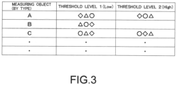
- Fig. 3 shows one example of a table in a case where one or two threshold level(s) are set for each measuring object W. On the table, one or two appropriate threshold level(s) are recorded for each measuring object W, taking into consideration the physical properties of the measuring object W.
- the measuring object W here is not limited to the measuring object itself, but may be set by being categorized appropriately by the name of the commodity, the name of the foreign matter desired to be detected, the type and material of the measuring object or foreign matter, or the like. Moreover, the measuring object W may be set as a set of the measuring object and the name of the foreign matter desired to be detected.
- the user is presented with a menu for selecting the measuring object W, which is the table index, and the user selects and inputs the measuring object W by using the input means 160 such as a mouse, a keyboard, a touch panel, a barcode reader, or the like.
- the threshold level setting means 140 reads threshold levels 1 and 2 for the selected measuring object W from the table and keeps the threshold levels so that the X-ray detection means 130 can refer to the threshold levels as predetermined threshold levels. At this time, the threshold levels do not have to be displayed on the selection menu presented to the user.
- the configuration for associating the measuring object W and the threshold level in the table is not limited to the configuration shown in Fig. 3 and may be arbitrarily determined according to a method of inputting the information specifying the measuring object W.
- a method of inputting the information specifying the measuring object W For example, in a case of presenting the measuring object W to the user to be selected and inputted as in the case of Fig. 3 , in addition to the method of constituting with one table as shown in Fig. 3 , it is also possible to adopt a method of constituting with two tables as shown in Figs. 4(a) and (b) .
- one table is constituted by a set of the measuring object W and a threshold number as shown in Fig.
- the other table is constituted by a set of a threshold number and a threshold level as shown in Fig. 4(b) , and the measuring object W and the threshold level are indirectly associated by relating both tables with the threshold number. Furthermore, in a case of inputting the information specifying the measuring object W by reading a barcode or QR code (registered trademark) with a barcode reader or by directly inputting the commodity number with the keyboard, by making the index in the table shown in Fig. 3 a number or a commodity number corresponding to the code indicating the measuring object W instead of the measuring object W, the measuring object W corresponding to the code or the commodity number and a threshold level can be associated.
- a barcode or QR code registered trademark
- the inspection means 170 inspects the measuring object based on the number of photons detected by the X-ray detection means 130 for each of one or more energy region(s). For example, an X-ray transmission image is generated based on the number of photons detected by the X-ray detection means 130 for each of the two energy regions shown in Fig. 2(a) , and predetermined processing such as calculating a difference between the images can be performed to generate an image, in which the measuring object W and the foreign matter contained therein are visualized with high contrast.
- the generated image is displayed on, for example, the display means 150.
- the result of the inspection itself does not necessarily have to be the output target, and, for example, a control signal of a sorter may be outputted based on the result of the inspection.
- the inspection means 170 may inspect the measuring object based on an amount corresponding to the number of photons detected by the X-ray detection means 130 for each of one or more energy region(s). For example, in the X-ray detection means 130, the energy of a detection signal, which is obtained by amplifying a charge of an electron-hole pair generated by the X-ray photons reached each X-ray detection element constituting the X-ray line sensor, is compared with the predetermined threshold level, and the charge amount, which is obtained by integrating the charge amount of the detection signal exceeded or not exceeded the threshold level with a predetermined time, is outputted as an integral charge amount of the X-ray detection element in the energy region defined by the threshold level.
- the integral charge amounts exceeding the respective threshold levels are successively taken into the memory. Then, a high-energy X-ray transmission image can be generated based on the integral charge amount exceeding the threshold level Vth2 on the high-energy side in each X-ray detection element. A low-energy X-ray transmission image can also be generated based on the charge amount obtained by subtracting the integral charge amount exceeding the threshold level Vth2 on the high-energy side from the integral charge amount exceeding the threshold level Vth1 on the low-energy side in each detection element.
- the inspection method performed by the inspection means 170 may be different for each measuring object W.
- image processing conditions e.g., a coefficient for each photon counting number and a calculation formula such as addition, subtraction, or the like
- the inspection method for the measuring object W selected and inputted in the threshold level setting means 140 may be executed with reference to the table at the time of execution of the processing by the inspection means 170.
- the inspection of the measuring object does not necessarily have to be performed by the image generation.
- the inspection of the measuring object may be performed by internally and directly calculating a difference between or comparing output data for each energy region (such as the number of photons for each detection element).
- an optimal threshold level can be set according to the physical properties of the measuring object itself and the foreign matter that may be contained therein, it is possible to generate a clear image with high contrast between the measuring object and the foreign matter, enabling accurate inspection of the measuring object regardless of the physical properties of the measuring object and the like. Furthermore, since it is necessary to only select the measuring object W in order to set the threshold level, even a user who is not familiar with the principle of X-ray inspection or the like can perform the setting quickly and correctly.
- the present invention is not limited to the above embodiments.
- the line sensor is exemplified as the X-ray sensor
- the X-ray sensor may be an area sensor or may adopt a time delay integration (TDI) sensor or a time-delayed summation (TDS) sensor to improve the contrast or the S/N ratio.
- TDI time delay integration
- TDS time-delayed summation
Landscapes
- Health & Medical Sciences (AREA)
- Physics & Mathematics (AREA)
- Life Sciences & Earth Sciences (AREA)
- General Physics & Mathematics (AREA)
- Immunology (AREA)
- Chemical & Material Sciences (AREA)
- Analytical Chemistry (AREA)
- Biochemistry (AREA)
- General Health & Medical Sciences (AREA)
- Pathology (AREA)
- Molecular Biology (AREA)
- Spectroscopy & Molecular Physics (AREA)
- Toxicology (AREA)
- High Energy & Nuclear Physics (AREA)
- Analysing Materials By The Use Of Radiation (AREA)
- Measurement Of Radiation (AREA)
Claims (4)
- Röntgenstrahlenprüfvorrichtung zum Prüfen eines Messobjekts (W), umfassend:ein Röntgenstrahlenemissionsmittel (110) zum Aussenden von Röntgenstrahlen auf ein Messobjekt (W);ein Fördermittel (120), welches das darauf platzierte Messobjekt (W) fördert, wobei das Fördermittel (120) ein Bandförderer ist;ein Röntgenstrahlenerfassungsmittel (130) zum Erfassen eines Röntgenstrahlenphotons, welches durch das Messobjekt (W) hindurchtritt, durch Unterscheiden von Energie, die das Röntgenstrahlenphoton besitzt, in einen oder mehrere Energiebereiche in Übereinstimmung mit einem vorbestimmten Schwellenwert, während das Messobjekt (W) durch das Fördermittel (120) bewegt wird;ein Speichermittel (141) zum Speichern des Messobjekts (W) und des Schwellenwerts, die einander direkt oder indirekt zugeordnet sind;ein Schwellenwerteinstellmittel (140) zum Zurückgreifen auf das Speichermittel (141), um einen Schwellenwert für das Messobjekt zu halten, der durch eingegebene Informationen spezifiziert wird, so dass das Röntgenstrahlenerfassungsmittel (130) auf den Schwellenwert als den vorbestimmten Schwellenwert zurückgreifen kann; undein Prüfmittel (170) zum Prüfen des Messobjekts (W) anhand einer Anzahl von Photonen oder einer Menge, die der Anzahl der Photonen entspricht, die von dem Röntgenstrahlenerfassungsmittel (130) für jeden der einen oder mehreren Energiebereiche erfasst werden.
- Röntgenstrahlenprüfvorrichtung nach Anspruch 1, wobei das Prüfmittel (170) ein Röntgenstrahlenübertragungsbild für jeden der einen oder mehreren Energiebereiche anhand der Anzahl der Photonen oder der Menge erzeugt, die der Anzahl der Photonen entspricht, die von dem Röntgenstrahlenerfassungsmittel (130) für jeden der einen oder mehreren Energiebereiche erfasst werden und als Prüfergebnis des Messobjekts (W) ein Bild ausgibt, das durch Ausführen eines vorbestimmten Verarbeitens an jedem Röntgenstrahlenübertragungsbild erhalten wird.
- Röntgenstrahlenprüfvorrichtung nach Anspruch 1, wobei das Speichermittel (141) ferner Informationen speichert, die ein Prüfverfahren des Messobjekts (W) in dem Prüfmittel (170) angeben, die dem Messobjekt (W) zugeordnet sind, und
das Prüfmittel (170) auf das Speichermittel (141) zurückgreift und das Messobjekt (W) durch ein Prüfverfahren für das Messobjekt (W) prüft, das durch Informationen spezifiziert wird, die in das Schwellenwerteinstellmittel (140) eingegeben werden. - Röntgenstrahlenprüfvorrichtung nach einem der Ansprüche 1 bis 3, wobei der Betrag, welcher der Anzahl der Photonen entspricht, ein Ladungsbetrag ist.
Applications Claiming Priority (2)
| Application Number | Priority Date | Filing Date | Title |
|---|---|---|---|
| JP2016196714 | 2016-10-04 | ||
| PCT/JP2017/033982 WO2018066364A1 (ja) | 2016-10-04 | 2017-09-20 | X線検査装置 |
Publications (4)
| Publication Number | Publication Date |
|---|---|
| EP3524969A1 EP3524969A1 (de) | 2019-08-14 |
| EP3524969A4 EP3524969A4 (de) | 2020-08-12 |
| EP3524969B1 true EP3524969B1 (de) | 2024-08-21 |
| EP3524969C0 EP3524969C0 (de) | 2024-08-21 |
Family
ID=61831446
Family Applications (1)
| Application Number | Title | Priority Date | Filing Date |
|---|---|---|---|
| EP17858203.7A Active EP3524969B1 (de) | 2016-10-04 | 2017-09-20 | Röntgenstrahlinspektionsvorrichtung |
Country Status (6)
| Country | Link |
|---|---|
| US (1) | US10859516B2 (de) |
| EP (1) | EP3524969B1 (de) |
| JP (1) | JP6569070B2 (de) |
| CN (1) | CN109804239B (de) |
| PL (1) | PL3524969T3 (de) |
| WO (1) | WO2018066364A1 (de) |
Families Citing this family (8)
| Publication number | Priority date | Publication date | Assignee | Title |
|---|---|---|---|---|
| US10859516B2 (en) * | 2016-10-04 | 2020-12-08 | System Square Inc. | X-ray inspection apparatus |
| US11047813B2 (en) * | 2018-05-21 | 2021-06-29 | Volodymyr Pavlovich ROMBAKH | Non-invasive monitoring of atomic reactions to detect structural failure |
| JP7123989B2 (ja) * | 2020-01-30 | 2022-08-23 | アンリツ株式会社 | X線検査装置 |
| JP2023056656A (ja) * | 2021-10-08 | 2023-04-20 | 株式会社 システムスクエア | X線検査装置及びプログラム |
| JP7630406B2 (ja) * | 2021-10-15 | 2025-02-17 | アンリツ株式会社 | 物品検査装置 |
| JP2023132587A (ja) | 2022-03-11 | 2023-09-22 | 株式会社イシダ | X線検査装置及びその調整方法 |
| WO2024180606A1 (ja) * | 2023-02-27 | 2024-09-06 | 株式会社システムスクエア | X線検査装置及びプログラム |
| JP2024132563A (ja) | 2023-03-17 | 2024-10-01 | 株式会社イシダ | X線検査装置及びx線検査装置の感度補正方法 |
Citations (6)
| Publication number | Priority date | Publication date | Assignee | Title |
|---|---|---|---|---|
| US20020191738A1 (en) | 2000-09-29 | 2002-12-19 | Mazess Richard B. | Method of inspecting meat for bone content using dual energy x-ray attenuation |
| JP2004008460A (ja) | 2002-06-06 | 2004-01-15 | Kawasaki Heavy Ind Ltd | X線エネルギー分析イメージング装置 |
| JP2007232586A (ja) | 2006-03-01 | 2007-09-13 | Anritsu Sanki System Co Ltd | X線検査装置 |
| JP2009014624A (ja) | 2007-07-06 | 2009-01-22 | Hamamatsu Photonics Kk | 放射線検出装置及び放射線検出方法 |
| JP2010091483A (ja) | 2008-10-09 | 2010-04-22 | Anritsu Sanki System Co Ltd | 異物検出方法および装置 |
| US20150287193A1 (en) | 2012-12-19 | 2015-10-08 | Kabushiki Kaisha Toshiba | X-ray ct apparatus, image processing apparatus, and image processing method |
Family Cites Families (12)
| Publication number | Priority date | Publication date | Assignee | Title |
|---|---|---|---|---|
| JPH0810250A (ja) | 1994-06-30 | 1996-01-16 | Toshiba Corp | X線ctスキャナ |
| JP4665358B2 (ja) | 2001-07-31 | 2011-04-06 | 株式会社島津製作所 | X線撮影装置 |
| DE102005037367B3 (de) * | 2005-08-08 | 2007-04-05 | Siemens Ag | Verfahren für eine Röntgeneinrichtung |
| CN101210971A (zh) * | 2006-12-31 | 2008-07-02 | 同方威视技术股份有限公司 | 一种放射性物质射线能区识别方法及射线能区探测系统 |
| JP5368772B2 (ja) * | 2008-11-11 | 2013-12-18 | 浜松ホトニクス株式会社 | 放射線検出装置、放射線画像取得システム及び放射線の検出方法 |
| JP2011203160A (ja) * | 2010-03-26 | 2011-10-13 | Tokyo Institute Of Technology | X線ct画像再構成方法及びx線ct画像再構成プログラム |
| WO2013024890A1 (ja) * | 2011-08-18 | 2013-02-21 | 株式会社東芝 | 光子計数型のx線コンピュータ断層装置及び散乱線補正方法 |
| US9285326B2 (en) * | 2012-06-19 | 2016-03-15 | Kabushiki Kaisha Toshiba | Sparse and energy discriminating collimated detector elements to assist scatter evaluation in CT imaging |
| DE102013204264A1 (de) * | 2013-03-12 | 2014-09-18 | Siemens Aktiengesellschaft | Verfahren zur Aufnahme eines Röntgenbildes und Röntgensystem |
| CN104422704B (zh) * | 2013-08-21 | 2017-07-25 | 同方威视技术股份有限公司 | 对x光能谱ct的能谱信息进行分解的方法和对应的重建方法 |
| EP2951615B1 (de) * | 2013-10-09 | 2016-08-24 | Koninklijke Philips N.V. | Verfahren und vorrichtung zur erzeugung eines energieaufgelösten röntgenbildes mit angepasster energieschwelle |
| US10859516B2 (en) * | 2016-10-04 | 2020-12-08 | System Square Inc. | X-ray inspection apparatus |
-
2017
- 2017-09-20 US US16/334,350 patent/US10859516B2/en active Active
- 2017-09-20 EP EP17858203.7A patent/EP3524969B1/de active Active
- 2017-09-20 CN CN201780054153.6A patent/CN109804239B/zh active Active
- 2017-09-20 PL PL17858203.7T patent/PL3524969T3/pl unknown
- 2017-09-20 WO PCT/JP2017/033982 patent/WO2018066364A1/ja not_active Ceased
- 2017-09-20 JP JP2018543830A patent/JP6569070B2/ja not_active Ceased
Patent Citations (6)
| Publication number | Priority date | Publication date | Assignee | Title |
|---|---|---|---|---|
| US20020191738A1 (en) | 2000-09-29 | 2002-12-19 | Mazess Richard B. | Method of inspecting meat for bone content using dual energy x-ray attenuation |
| JP2004008460A (ja) | 2002-06-06 | 2004-01-15 | Kawasaki Heavy Ind Ltd | X線エネルギー分析イメージング装置 |
| JP2007232586A (ja) | 2006-03-01 | 2007-09-13 | Anritsu Sanki System Co Ltd | X線検査装置 |
| JP2009014624A (ja) | 2007-07-06 | 2009-01-22 | Hamamatsu Photonics Kk | 放射線検出装置及び放射線検出方法 |
| JP2010091483A (ja) | 2008-10-09 | 2010-04-22 | Anritsu Sanki System Co Ltd | 異物検出方法および装置 |
| US20150287193A1 (en) | 2012-12-19 | 2015-10-08 | Kabushiki Kaisha Toshiba | X-ray ct apparatus, image processing apparatus, and image processing method |
Non-Patent Citations (7)
| Title |
|---|
| "Doctoral Thesis", 25 January 2012, FRIEDRICH-ALEXANDER-UNIVERSITÄT ERLANGEN-NÜRNBERG, Erlangen-Nürnberg, article GUNI EWALD: "Untersuchung von CdTe als Sensormaterial für die spektroskopische Röntgenbildgebung", pages: 1 - 121, XP093280960 |
| "Semiconductor Detector Systems", 1 August 2005, OXFORD UNIVERSITY PRESS, ISBN: 0-19-852784-5, article HELMUTH SPIELER: "4.7 Threshold discriminator systems", pages: 169 - 174, XP009561305, DOI: 10.1093/acprof:oso/9780198527848.003.0004 |
| "Semiconductor Detector Systems", 1 August 2005, OXFORD UNIVERSITY PRESS, ISBN: 0-19-852784-5, article HELMUTH SPIELER: "8.9 Emerging applications", pages: 367 - 372, XP009561304, DOI: 10.1093/acprof:oso/9780198527848.003.0008 |
| ANONYMOUS: "Multix NP 100 system", BROCHURE MULTIX NP 100 SYSTEM, MULTIX DETECTION, 1 October 2014 (2014-10-01), pages 1 - 2, XP093280949, Retrieved from the Internet <URL:https://web.archive.org/web/20110929213521/http://www.multixdetection.com/> |
| FULLADOSA E, GOU P, MUÑOZ I: "Effect of dry-cured ham composition on X-ray multi energy spectra", FOOD CONTROL, BUTTERWORTH, LONDON, GB, vol. 70, 20 May 2016 (2016-05-20), GB , pages 41 - 47, XP029651631, ISSN: 0956-7135, DOI: 10.1016/j.foodcont.2016.05.025 |
| WATABIKI HIROAKI, TOSHIKAZU TAKEDA, SATOSHI MITANI, TAKESHI YAMAZAKI, MANABU INOUE, HIROYUKI KOBA, ITARU MIYAZAKI, NAOYA SAITO, SY: "Development of Dual-Energy X-ray Inspection System", ANRITSU TECHNICAL REVIEW, no. 20, 1 March 2013 (2013-03-01), pages 59 - 66, XP093280976 |
| WHITWORTH JOSEPH JAMES: "Dylog targets detection of similar density contaminants", DISPATCHES FROM EMBALLAGE 2014, PARIS, FOOD NAVIGATOR EUROPE, 19 November 2014 (2014-11-19), pages 1 - 3, XP093280953, Retrieved from the Internet <URL:https://www.foodnavigator.com/Article/2014/11/19/Dylog-launches-Dynamite-XFAN-at-Emballage/> |
Also Published As
| Publication number | Publication date |
|---|---|
| US20190212464A1 (en) | 2019-07-11 |
| PL3524969T3 (pl) | 2024-10-14 |
| CN109804239B (zh) | 2021-10-15 |
| CN109804239A (zh) | 2019-05-24 |
| JP6569070B2 (ja) | 2019-09-04 |
| EP3524969A1 (de) | 2019-08-14 |
| US10859516B2 (en) | 2020-12-08 |
| JPWO2018066364A1 (ja) | 2019-03-22 |
| EP3524969C0 (de) | 2024-08-21 |
| WO2018066364A1 (ja) | 2018-04-12 |
| EP3524969A4 (de) | 2020-08-12 |
Similar Documents
| Publication | Publication Date | Title |
|---|---|---|
| EP3524969B1 (de) | Röntgenstrahlinspektionsvorrichtung | |
| CN100376212C (zh) | 具有能量识别探测器的计算机断层造影设备 | |
| US8374993B2 (en) | Radioactive isotope identification | |
| US10845319B2 (en) | Dual-energy microfocus radiographic imaging method for meat inspection | |
| JP2012513023A5 (de) | ||
| EP3048440A1 (de) | Inspektionsvorrichtung | |
| JP2018141736A (ja) | X線検査装置 | |
| US20180164231A1 (en) | Dual-energy microfocus radiographic imaging method for meat inspection | |
| JP5452131B2 (ja) | X線検出器およびx線検査装置 | |
| EP3546930B1 (de) | Strahlungserkennungsvorrichtung, strahlungsbilderfassungsvorrichtung und strahlungsbilderfassungsverfahren | |
| JP7001327B2 (ja) | 異物検出装置および異物検出方法 | |
| JP7060446B2 (ja) | X線ラインセンサ及びそれを用いたx線異物検出装置 | |
| JP5356184B2 (ja) | 物品検査装置 | |
| JP6979185B2 (ja) | X線検査装置 | |
| JP6797539B2 (ja) | 異物検出装置および異物検出方法 | |
| JP6491125B2 (ja) | 異物検出装置および異物検出方法 | |
| JP6625470B2 (ja) | 異物検出装置および異物検出方法 | |
| JP6655570B2 (ja) | 物品検査装置およびその検査対象品種切替方法 | |
| WO2024180606A1 (ja) | X線検査装置及びプログラム | |
| JP2009300295A (ja) | フォトンカウント検出器 | |
| EP4563985A1 (de) | Röntgenstrahlinspektionsvorrichtu ng | |
| JP6139391B2 (ja) | 放射能検査装置及び方法 | |
| JP6606454B2 (ja) | 異物検出装置および異物検出方法 | |
| CN205175930U (zh) | 用于物质分辨的标定装置和标定系统 | |
| JP2023056656A (ja) | X線検査装置及びプログラム |
Legal Events
| Date | Code | Title | Description |
|---|---|---|---|
| STAA | Information on the status of an ep patent application or granted ep patent |
Free format text: STATUS: THE INTERNATIONAL PUBLICATION HAS BEEN MADE |
|
| PUAI | Public reference made under article 153(3) epc to a published international application that has entered the european phase |
Free format text: ORIGINAL CODE: 0009012 |
|
| STAA | Information on the status of an ep patent application or granted ep patent |
Free format text: STATUS: REQUEST FOR EXAMINATION WAS MADE |
|
| 17P | Request for examination filed |
Effective date: 20190307 |
|
| AK | Designated contracting states |
Kind code of ref document: A1 Designated state(s): AL AT BE BG CH CY CZ DE DK EE ES FI FR GB GR HR HU IE IS IT LI LT LU LV MC MK MT NL NO PL PT RO RS SE SI SK SM TR |
|
| AX | Request for extension of the european patent |
Extension state: BA ME |
|
| DAV | Request for validation of the european patent (deleted) | ||
| DAX | Request for extension of the european patent (deleted) | ||
| A4 | Supplementary search report drawn up and despatched |
Effective date: 20200709 |
|
| RIC1 | Information provided on ipc code assigned before grant |
Ipc: G01N 23/087 20180101ALI20200704BHEP Ipc: G01N 23/18 20180101ALI20200704BHEP Ipc: G01N 23/04 20180101AFI20200704BHEP Ipc: G01T 1/36 20060101ALI20200704BHEP Ipc: G01T 1/17 20060101ALI20200704BHEP |
|
| STAA | Information on the status of an ep patent application or granted ep patent |
Free format text: STATUS: EXAMINATION IS IN PROGRESS |
|
| 17Q | First examination report despatched |
Effective date: 20220601 |
|
| GRAP | Despatch of communication of intention to grant a patent |
Free format text: ORIGINAL CODE: EPIDOSNIGR1 |
|
| STAA | Information on the status of an ep patent application or granted ep patent |
Free format text: STATUS: GRANT OF PATENT IS INTENDED |
|
| RIC1 | Information provided on ipc code assigned before grant |
Ipc: G01N 23/087 20180101ALI20240216BHEP Ipc: G01T 1/24 20060101ALI20240216BHEP Ipc: G01N 23/18 20180101ALI20240216BHEP Ipc: G01N 23/04 20180101AFI20240216BHEP |
|
| INTG | Intention to grant announced |
Effective date: 20240315 |
|
| GRAS | Grant fee paid |
Free format text: ORIGINAL CODE: EPIDOSNIGR3 |
|
| GRAA | (expected) grant |
Free format text: ORIGINAL CODE: 0009210 |
|
| STAA | Information on the status of an ep patent application or granted ep patent |
Free format text: STATUS: THE PATENT HAS BEEN GRANTED |
|
| RAP3 | Party data changed (applicant data changed or rights of an application transferred) |
Owner name: SYSTEM SQUARE INC. |
|
| AK | Designated contracting states |
Kind code of ref document: B1 Designated state(s): AL AT BE BG CH CY CZ DE DK EE ES FI FR GB GR HR HU IE IS IT LI LT LU LV MC MK MT NL NO PL PT RO RS SE SI SK SM TR |
|
| REG | Reference to a national code |
Ref country code: GB Ref legal event code: FG4D |
|
| REG | Reference to a national code |
Ref country code: CH Ref legal event code: EP |
|
| REG | Reference to a national code |
Ref country code: IE Ref legal event code: FG4D |
|
| REG | Reference to a national code |
Ref country code: DE Ref legal event code: R096 Ref document number: 602017084315 Country of ref document: DE |
|
| U01 | Request for unitary effect filed |
Effective date: 20240821 |
|
| U07 | Unitary effect registered |
Designated state(s): AT BE BG DE DK EE FI FR IT LT LU LV MT NL PT SE SI Effective date: 20240827 |
|
| U20 | Renewal fee for the european patent with unitary effect paid |
Year of fee payment: 8 Effective date: 20240924 |
|
| PG25 | Lapsed in a contracting state [announced via postgrant information from national office to epo] |
Ref country code: NO Free format text: LAPSE BECAUSE OF FAILURE TO SUBMIT A TRANSLATION OF THE DESCRIPTION OR TO PAY THE FEE WITHIN THE PRESCRIBED TIME-LIMIT Effective date: 20241121 |
|
| PG25 | Lapsed in a contracting state [announced via postgrant information from national office to epo] |
Ref country code: GR Free format text: LAPSE BECAUSE OF FAILURE TO SUBMIT A TRANSLATION OF THE DESCRIPTION OR TO PAY THE FEE WITHIN THE PRESCRIBED TIME-LIMIT Effective date: 20241122 |
|
| PG25 | Lapsed in a contracting state [announced via postgrant information from national office to epo] |
Ref country code: IS Free format text: LAPSE BECAUSE OF FAILURE TO SUBMIT A TRANSLATION OF THE DESCRIPTION OR TO PAY THE FEE WITHIN THE PRESCRIBED TIME-LIMIT Effective date: 20241221 |
|
| PG25 | Lapsed in a contracting state [announced via postgrant information from national office to epo] |
Ref country code: HR Free format text: LAPSE BECAUSE OF FAILURE TO SUBMIT A TRANSLATION OF THE DESCRIPTION OR TO PAY THE FEE WITHIN THE PRESCRIBED TIME-LIMIT Effective date: 20240821 |
|
| PG25 | Lapsed in a contracting state [announced via postgrant information from national office to epo] |
Ref country code: RS Free format text: LAPSE BECAUSE OF FAILURE TO SUBMIT A TRANSLATION OF THE DESCRIPTION OR TO PAY THE FEE WITHIN THE PRESCRIBED TIME-LIMIT Effective date: 20241121 Ref country code: ES Free format text: LAPSE BECAUSE OF FAILURE TO SUBMIT A TRANSLATION OF THE DESCRIPTION OR TO PAY THE FEE WITHIN THE PRESCRIBED TIME-LIMIT Effective date: 20240821 |
|
| PG25 | Lapsed in a contracting state [announced via postgrant information from national office to epo] |
Ref country code: RS Free format text: LAPSE BECAUSE OF FAILURE TO SUBMIT A TRANSLATION OF THE DESCRIPTION OR TO PAY THE FEE WITHIN THE PRESCRIBED TIME-LIMIT Effective date: 20241121 Ref country code: NO Free format text: LAPSE BECAUSE OF FAILURE TO SUBMIT A TRANSLATION OF THE DESCRIPTION OR TO PAY THE FEE WITHIN THE PRESCRIBED TIME-LIMIT Effective date: 20241121 Ref country code: IS Free format text: LAPSE BECAUSE OF FAILURE TO SUBMIT A TRANSLATION OF THE DESCRIPTION OR TO PAY THE FEE WITHIN THE PRESCRIBED TIME-LIMIT Effective date: 20241221 Ref country code: HR Free format text: LAPSE BECAUSE OF FAILURE TO SUBMIT A TRANSLATION OF THE DESCRIPTION OR TO PAY THE FEE WITHIN THE PRESCRIBED TIME-LIMIT Effective date: 20240821 Ref country code: GR Free format text: LAPSE BECAUSE OF FAILURE TO SUBMIT A TRANSLATION OF THE DESCRIPTION OR TO PAY THE FEE WITHIN THE PRESCRIBED TIME-LIMIT Effective date: 20241122 Ref country code: ES Free format text: LAPSE BECAUSE OF FAILURE TO SUBMIT A TRANSLATION OF THE DESCRIPTION OR TO PAY THE FEE WITHIN THE PRESCRIBED TIME-LIMIT Effective date: 20240821 |
|
| PG25 | Lapsed in a contracting state [announced via postgrant information from national office to epo] |
Ref country code: SM Free format text: LAPSE BECAUSE OF FAILURE TO SUBMIT A TRANSLATION OF THE DESCRIPTION OR TO PAY THE FEE WITHIN THE PRESCRIBED TIME-LIMIT Effective date: 20240821 |
|
| PG25 | Lapsed in a contracting state [announced via postgrant information from national office to epo] |
Ref country code: CZ Free format text: LAPSE BECAUSE OF FAILURE TO SUBMIT A TRANSLATION OF THE DESCRIPTION OR TO PAY THE FEE WITHIN THE PRESCRIBED TIME-LIMIT Effective date: 20240821 |
|
| PG25 | Lapsed in a contracting state [announced via postgrant information from national office to epo] |
Ref country code: SK Free format text: LAPSE BECAUSE OF FAILURE TO SUBMIT A TRANSLATION OF THE DESCRIPTION OR TO PAY THE FEE WITHIN THE PRESCRIBED TIME-LIMIT Effective date: 20240821 |
|
| REG | Reference to a national code |
Ref country code: CH Ref legal event code: PL |
|
| PLBI | Opposition filed |
Free format text: ORIGINAL CODE: 0009260 |
|
| PLAX | Notice of opposition and request to file observation + time limit sent |
Free format text: ORIGINAL CODE: EPIDOSNOBS2 |
|
| 26 | Opposition filed |
Opponent name: METTLER-TOLEDO GMBH Effective date: 20250520 |
|
| PG25 | Lapsed in a contracting state [announced via postgrant information from national office to epo] |
Ref country code: MC Free format text: LAPSE BECAUSE OF FAILURE TO SUBMIT A TRANSLATION OF THE DESCRIPTION OR TO PAY THE FEE WITHIN THE PRESCRIBED TIME-LIMIT Effective date: 20240821 |
|
| GBPC | Gb: european patent ceased through non-payment of renewal fee |
Effective date: 20241121 |
|
| PG25 | Lapsed in a contracting state [announced via postgrant information from national office to epo] |
Ref country code: CH Free format text: LAPSE BECAUSE OF NON-PAYMENT OF DUE FEES Effective date: 20240930 |
|
| PG25 | Lapsed in a contracting state [announced via postgrant information from national office to epo] |
Ref country code: IE Free format text: LAPSE BECAUSE OF NON-PAYMENT OF DUE FEES Effective date: 20240920 |
|
| PLBB | Reply of patent proprietor to notice(s) of opposition received |
Free format text: ORIGINAL CODE: EPIDOSNOBS3 |
|
| PGFP | Annual fee paid to national office [announced via postgrant information from national office to epo] |
Ref country code: PL Payment date: 20250905 Year of fee payment: 9 |
|
| PG25 | Lapsed in a contracting state [announced via postgrant information from national office to epo] |
Ref country code: GB Free format text: LAPSE BECAUSE OF NON-PAYMENT OF DUE FEES Effective date: 20241121 |
|
| U20 | Renewal fee for the european patent with unitary effect paid |
Year of fee payment: 9 Effective date: 20250925 |
|
| PG25 | Lapsed in a contracting state [announced via postgrant information from national office to epo] |
Ref country code: RO Free format text: LAPSE BECAUSE OF FAILURE TO SUBMIT A TRANSLATION OF THE DESCRIPTION OR TO PAY THE FEE WITHIN THE PRESCRIBED TIME-LIMIT Effective date: 20240821 |