EP3524317A1 - In einer hand haltbares gerät zur elektrisch unterstützten hautbehandlung - Google Patents
In einer hand haltbares gerät zur elektrisch unterstützten hautbehandlung Download PDFInfo
- Publication number
- EP3524317A1 EP3524317A1 EP19164931.8A EP19164931A EP3524317A1 EP 3524317 A1 EP3524317 A1 EP 3524317A1 EP 19164931 A EP19164931 A EP 19164931A EP 3524317 A1 EP3524317 A1 EP 3524317A1
- Authority
- EP
- European Patent Office
- Prior art keywords
- housing
- electrode
- vibrator
- skin
- batteries
- Prior art date
- Legal status (The legal status is an assumption and is not a legal conclusion. Google has not performed a legal analysis and makes no representation as to the accuracy of the status listed.)
- Granted
Links
Images



Classifications
-
- A—HUMAN NECESSITIES
- A61—MEDICAL OR VETERINARY SCIENCE; HYGIENE
- A61N—ELECTROTHERAPY; MAGNETOTHERAPY; RADIATION THERAPY; ULTRASOUND THERAPY
- A61N1/00—Electrotherapy; Circuits therefor
- A61N1/18—Applying electric currents by contact electrodes
- A61N1/32—Applying electric currents by contact electrodes alternating or intermittent currents
- A61N1/322—Electromedical brushes, combs, massage devices
-
- A—HUMAN NECESSITIES
- A61—MEDICAL OR VETERINARY SCIENCE; HYGIENE
- A61M—DEVICES FOR INTRODUCING MEDIA INTO, OR ONTO, THE BODY; DEVICES FOR TRANSDUCING BODY MEDIA OR FOR TAKING MEDIA FROM THE BODY; DEVICES FOR PRODUCING OR ENDING SLEEP OR STUPOR
- A61M37/00—Other apparatus for introducing media into the body; Percutany, i.e. introducing medicines into the body by diffusion through the skin
-
- A—HUMAN NECESSITIES
- A61—MEDICAL OR VETERINARY SCIENCE; HYGIENE
- A61N—ELECTROTHERAPY; MAGNETOTHERAPY; RADIATION THERAPY; ULTRASOUND THERAPY
- A61N1/00—Electrotherapy; Circuits therefor
- A61N1/18—Applying electric currents by contact electrodes
- A61N1/32—Applying electric currents by contact electrodes alternating or intermittent currents
- A61N1/328—Applying electric currents by contact electrodes alternating or intermittent currents for improving the appearance of the skin, e.g. facial toning or wrinkle treatment
-
- A—HUMAN NECESSITIES
- A61—MEDICAL OR VETERINARY SCIENCE; HYGIENE
- A61H—PHYSICAL THERAPY APPARATUS, e.g. DEVICES FOR LOCATING OR STIMULATING REFLEX POINTS IN THE BODY; ARTIFICIAL RESPIRATION; MASSAGE; BATHING DEVICES FOR SPECIAL THERAPEUTIC OR HYGIENIC PURPOSES OR SPECIFIC PARTS OF THE BODY
- A61H23/00—Percussion or vibration massage, e.g. using supersonic vibration; Suction-vibration massage; Massage with moving diaphragms
-
- A—HUMAN NECESSITIES
- A61—MEDICAL OR VETERINARY SCIENCE; HYGIENE
- A61H—PHYSICAL THERAPY APPARATUS, e.g. DEVICES FOR LOCATING OR STIMULATING REFLEX POINTS IN THE BODY; ARTIFICIAL RESPIRATION; MASSAGE; BATHING DEVICES FOR SPECIAL THERAPEUTIC OR HYGIENIC PURPOSES OR SPECIFIC PARTS OF THE BODY
- A61H23/00—Percussion or vibration massage, e.g. using supersonic vibration; Suction-vibration massage; Massage with moving diaphragms
- A61H23/02—Percussion or vibration massage, e.g. using supersonic vibration; Suction-vibration massage; Massage with moving diaphragms with electric or magnetic drive
-
- A—HUMAN NECESSITIES
- A61—MEDICAL OR VETERINARY SCIENCE; HYGIENE
- A61H—PHYSICAL THERAPY APPARATUS, e.g. DEVICES FOR LOCATING OR STIMULATING REFLEX POINTS IN THE BODY; ARTIFICIAL RESPIRATION; MASSAGE; BATHING DEVICES FOR SPECIAL THERAPEUTIC OR HYGIENIC PURPOSES OR SPECIFIC PARTS OF THE BODY
- A61H23/00—Percussion or vibration massage, e.g. using supersonic vibration; Suction-vibration massage; Massage with moving diaphragms
- A61H23/02—Percussion or vibration massage, e.g. using supersonic vibration; Suction-vibration massage; Massage with moving diaphragms with electric or magnetic drive
- A61H23/0254—Percussion or vibration massage, e.g. using supersonic vibration; Suction-vibration massage; Massage with moving diaphragms with electric or magnetic drive with rotary motor
- A61H23/0263—Percussion or vibration massage, e.g. using supersonic vibration; Suction-vibration massage; Massage with moving diaphragms with electric or magnetic drive with rotary motor using rotating unbalanced masses
-
- A—HUMAN NECESSITIES
- A61—MEDICAL OR VETERINARY SCIENCE; HYGIENE
- A61H—PHYSICAL THERAPY APPARATUS, e.g. DEVICES FOR LOCATING OR STIMULATING REFLEX POINTS IN THE BODY; ARTIFICIAL RESPIRATION; MASSAGE; BATHING DEVICES FOR SPECIAL THERAPEUTIC OR HYGIENIC PURPOSES OR SPECIFIC PARTS OF THE BODY
- A61H7/00—Devices for suction-kneading massage; Devices for massaging the skin by rubbing or brushing not otherwise provided for
- A61H7/002—Devices for suction-kneading massage; Devices for massaging the skin by rubbing or brushing not otherwise provided for by rubbing or brushing
-
- A—HUMAN NECESSITIES
- A61—MEDICAL OR VETERINARY SCIENCE; HYGIENE
- A61H—PHYSICAL THERAPY APPARATUS, e.g. DEVICES FOR LOCATING OR STIMULATING REFLEX POINTS IN THE BODY; ARTIFICIAL RESPIRATION; MASSAGE; BATHING DEVICES FOR SPECIAL THERAPEUTIC OR HYGIENIC PURPOSES OR SPECIFIC PARTS OF THE BODY
- A61H7/00—Devices for suction-kneading massage; Devices for massaging the skin by rubbing or brushing not otherwise provided for
- A61H7/002—Devices for suction-kneading massage; Devices for massaging the skin by rubbing or brushing not otherwise provided for by rubbing or brushing
- A61H7/004—Devices for suction-kneading massage; Devices for massaging the skin by rubbing or brushing not otherwise provided for by rubbing or brushing power-driven, e.g. electrical
- A61H7/005—Devices for suction-kneading massage; Devices for massaging the skin by rubbing or brushing not otherwise provided for by rubbing or brushing power-driven, e.g. electrical hand-held
-
- A—HUMAN NECESSITIES
- A61—MEDICAL OR VETERINARY SCIENCE; HYGIENE
- A61N—ELECTROTHERAPY; MAGNETOTHERAPY; RADIATION THERAPY; ULTRASOUND THERAPY
- A61N1/00—Electrotherapy; Circuits therefor
- A61N1/02—Details
- A61N1/04—Electrodes
- A61N1/0404—Electrodes for external use
- A61N1/0408—Use-related aspects
- A61N1/0412—Specially adapted for transcutaneous electroporation, e.g. including drug reservoirs
-
- A—HUMAN NECESSITIES
- A61—MEDICAL OR VETERINARY SCIENCE; HYGIENE
- A61N—ELECTROTHERAPY; MAGNETOTHERAPY; RADIATION THERAPY; ULTRASOUND THERAPY
- A61N1/00—Electrotherapy; Circuits therefor
- A61N1/02—Details
- A61N1/04—Electrodes
- A61N1/0404—Electrodes for external use
- A61N1/0408—Use-related aspects
- A61N1/0428—Specially adapted for iontophoresis, e.g. AC, DC or including drug reservoirs
-
- A—HUMAN NECESSITIES
- A61—MEDICAL OR VETERINARY SCIENCE; HYGIENE
- A61N—ELECTROTHERAPY; MAGNETOTHERAPY; RADIATION THERAPY; ULTRASOUND THERAPY
- A61N1/00—Electrotherapy; Circuits therefor
- A61N1/02—Details
- A61N1/04—Electrodes
- A61N1/0404—Electrodes for external use
- A61N1/0472—Structure-related aspects
-
- A—HUMAN NECESSITIES
- A61—MEDICAL OR VETERINARY SCIENCE; HYGIENE
- A61N—ELECTROTHERAPY; MAGNETOTHERAPY; RADIATION THERAPY; ULTRASOUND THERAPY
- A61N1/00—Electrotherapy; Circuits therefor
- A61N1/02—Details
- A61N1/04—Electrodes
- A61N1/0404—Electrodes for external use
- A61N1/0472—Structure-related aspects
- A61N1/0476—Array electrodes (including any electrode arrangement with more than one electrode for at least one of the polarities)
-
- A—HUMAN NECESSITIES
- A61—MEDICAL OR VETERINARY SCIENCE; HYGIENE
- A61N—ELECTROTHERAPY; MAGNETOTHERAPY; RADIATION THERAPY; ULTRASOUND THERAPY
- A61N1/00—Electrotherapy; Circuits therefor
- A61N1/18—Applying electric currents by contact electrodes
- A61N1/20—Applying electric currents by contact electrodes continuous direct currents
- A61N1/30—Apparatus for iontophoresis, i.e. transfer of media in ionic state by an electromotoric force into the body, or cataphoresis
-
- A—HUMAN NECESSITIES
- A61—MEDICAL OR VETERINARY SCIENCE; HYGIENE
- A61N—ELECTROTHERAPY; MAGNETOTHERAPY; RADIATION THERAPY; ULTRASOUND THERAPY
- A61N1/00—Electrotherapy; Circuits therefor
- A61N1/18—Applying electric currents by contact electrodes
- A61N1/32—Applying electric currents by contact electrodes alternating or intermittent currents
- A61N1/325—Applying electric currents by contact electrodes alternating or intermittent currents for iontophoresis, i.e. transfer of media in ionic state by an electromotoric force into the body
-
- A—HUMAN NECESSITIES
- A61—MEDICAL OR VETERINARY SCIENCE; HYGIENE
- A61N—ELECTROTHERAPY; MAGNETOTHERAPY; RADIATION THERAPY; ULTRASOUND THERAPY
- A61N1/00—Electrotherapy; Circuits therefor
- A61N1/18—Applying electric currents by contact electrodes
- A61N1/32—Applying electric currents by contact electrodes alternating or intermittent currents
- A61N1/327—Applying electric currents by contact electrodes alternating or intermittent currents for enhancing the absorption properties of tissue, e.g. by electroporation
-
- A—HUMAN NECESSITIES
- A61—MEDICAL OR VETERINARY SCIENCE; HYGIENE
- A61H—PHYSICAL THERAPY APPARATUS, e.g. DEVICES FOR LOCATING OR STIMULATING REFLEX POINTS IN THE BODY; ARTIFICIAL RESPIRATION; MASSAGE; BATHING DEVICES FOR SPECIAL THERAPEUTIC OR HYGIENIC PURPOSES OR SPECIFIC PARTS OF THE BODY
- A61H2201/00—Characteristics of apparatus not provided for in the preceding codes
- A61H2201/01—Constructive details
- A61H2201/0119—Support for the device
- A61H2201/0153—Support for the device hand-held
-
- A—HUMAN NECESSITIES
- A61—MEDICAL OR VETERINARY SCIENCE; HYGIENE
- A61H—PHYSICAL THERAPY APPARATUS, e.g. DEVICES FOR LOCATING OR STIMULATING REFLEX POINTS IN THE BODY; ARTIFICIAL RESPIRATION; MASSAGE; BATHING DEVICES FOR SPECIAL THERAPEUTIC OR HYGIENIC PURPOSES OR SPECIFIC PARTS OF THE BODY
- A61H2201/00—Characteristics of apparatus not provided for in the preceding codes
- A61H2201/10—Characteristics of apparatus not provided for in the preceding codes with further special therapeutic means, e.g. electrotherapy, magneto therapy or radiation therapy, chromo therapy, infrared or ultraviolet therapy
-
- A—HUMAN NECESSITIES
- A61—MEDICAL OR VETERINARY SCIENCE; HYGIENE
- A61H—PHYSICAL THERAPY APPARATUS, e.g. DEVICES FOR LOCATING OR STIMULATING REFLEX POINTS IN THE BODY; ARTIFICIAL RESPIRATION; MASSAGE; BATHING DEVICES FOR SPECIAL THERAPEUTIC OR HYGIENIC PURPOSES OR SPECIFIC PARTS OF THE BODY
- A61H2201/00—Characteristics of apparatus not provided for in the preceding codes
- A61H2201/10—Characteristics of apparatus not provided for in the preceding codes with further special therapeutic means, e.g. electrotherapy, magneto therapy or radiation therapy, chromo therapy, infrared or ultraviolet therapy
- A61H2201/105—Characteristics of apparatus not provided for in the preceding codes with further special therapeutic means, e.g. electrotherapy, magneto therapy or radiation therapy, chromo therapy, infrared or ultraviolet therapy with means for delivering media, e.g. drugs or cosmetics
-
- A—HUMAN NECESSITIES
- A61—MEDICAL OR VETERINARY SCIENCE; HYGIENE
- A61H—PHYSICAL THERAPY APPARATUS, e.g. DEVICES FOR LOCATING OR STIMULATING REFLEX POINTS IN THE BODY; ARTIFICIAL RESPIRATION; MASSAGE; BATHING DEVICES FOR SPECIAL THERAPEUTIC OR HYGIENIC PURPOSES OR SPECIFIC PARTS OF THE BODY
- A61H2201/00—Characteristics of apparatus not provided for in the preceding codes
- A61H2201/12—Driving means
- A61H2201/1207—Driving means with electric or magnetic drive
- A61H2201/1215—Rotary drive
-
- A—HUMAN NECESSITIES
- A61—MEDICAL OR VETERINARY SCIENCE; HYGIENE
- A61H—PHYSICAL THERAPY APPARATUS, e.g. DEVICES FOR LOCATING OR STIMULATING REFLEX POINTS IN THE BODY; ARTIFICIAL RESPIRATION; MASSAGE; BATHING DEVICES FOR SPECIAL THERAPEUTIC OR HYGIENIC PURPOSES OR SPECIFIC PARTS OF THE BODY
- A61H2201/00—Characteristics of apparatus not provided for in the preceding codes
- A61H2201/12—Driving means
- A61H2201/1253—Driving means driven by a human being, e.g. hand driven
-
- A—HUMAN NECESSITIES
- A61—MEDICAL OR VETERINARY SCIENCE; HYGIENE
- A61H—PHYSICAL THERAPY APPARATUS, e.g. DEVICES FOR LOCATING OR STIMULATING REFLEX POINTS IN THE BODY; ARTIFICIAL RESPIRATION; MASSAGE; BATHING DEVICES FOR SPECIAL THERAPEUTIC OR HYGIENIC PURPOSES OR SPECIFIC PARTS OF THE BODY
- A61H2201/00—Characteristics of apparatus not provided for in the preceding codes
- A61H2201/14—Special force transmission means, i.e. between the driving means and the interface with the user
- A61H2201/1418—Cam
-
- A—HUMAN NECESSITIES
- A61—MEDICAL OR VETERINARY SCIENCE; HYGIENE
- A61H—PHYSICAL THERAPY APPARATUS, e.g. DEVICES FOR LOCATING OR STIMULATING REFLEX POINTS IN THE BODY; ARTIFICIAL RESPIRATION; MASSAGE; BATHING DEVICES FOR SPECIAL THERAPEUTIC OR HYGIENIC PURPOSES OR SPECIFIC PARTS OF THE BODY
- A61H2201/00—Characteristics of apparatus not provided for in the preceding codes
- A61H2201/16—Physical interface with patient
- A61H2201/1602—Physical interface with patient kind of interface, e.g. head rest, knee support or lumbar support
- A61H2201/165—Wearable interfaces
-
- A—HUMAN NECESSITIES
- A61—MEDICAL OR VETERINARY SCIENCE; HYGIENE
- A61H—PHYSICAL THERAPY APPARATUS, e.g. DEVICES FOR LOCATING OR STIMULATING REFLEX POINTS IN THE BODY; ARTIFICIAL RESPIRATION; MASSAGE; BATHING DEVICES FOR SPECIAL THERAPEUTIC OR HYGIENIC PURPOSES OR SPECIFIC PARTS OF THE BODY
- A61H2201/00—Characteristics of apparatus not provided for in the preceding codes
- A61H2201/16—Physical interface with patient
- A61H2201/1602—Physical interface with patient kind of interface, e.g. head rest, knee support or lumbar support
- A61H2201/1654—Layer between the skin and massage elements, e.g. fluid or ball
-
- A—HUMAN NECESSITIES
- A61—MEDICAL OR VETERINARY SCIENCE; HYGIENE
- A61H—PHYSICAL THERAPY APPARATUS, e.g. DEVICES FOR LOCATING OR STIMULATING REFLEX POINTS IN THE BODY; ARTIFICIAL RESPIRATION; MASSAGE; BATHING DEVICES FOR SPECIAL THERAPEUTIC OR HYGIENIC PURPOSES OR SPECIFIC PARTS OF THE BODY
- A61H2201/00—Characteristics of apparatus not provided for in the preceding codes
- A61H2201/16—Physical interface with patient
- A61H2201/1657—Movement of interface, i.e. force application means
- A61H2201/1664—Movement of interface, i.e. force application means linear
- A61H2201/1669—Movement of interface, i.e. force application means linear moving along the body in a reciprocating manner
-
- A—HUMAN NECESSITIES
- A61—MEDICAL OR VETERINARY SCIENCE; HYGIENE
- A61H—PHYSICAL THERAPY APPARATUS, e.g. DEVICES FOR LOCATING OR STIMULATING REFLEX POINTS IN THE BODY; ARTIFICIAL RESPIRATION; MASSAGE; BATHING DEVICES FOR SPECIAL THERAPEUTIC OR HYGIENIC PURPOSES OR SPECIFIC PARTS OF THE BODY
- A61H2201/00—Characteristics of apparatus not provided for in the preceding codes
- A61H2201/16—Physical interface with patient
- A61H2201/1683—Surface of interface
- A61H2201/169—Physical characteristics of the surface, e.g. material, relief, texture or indicia
- A61H2201/1695—Enhanced pressure effect, e.g. substantially sharp projections, needles or pyramids
-
- A—HUMAN NECESSITIES
- A61—MEDICAL OR VETERINARY SCIENCE; HYGIENE
- A61H—PHYSICAL THERAPY APPARATUS, e.g. DEVICES FOR LOCATING OR STIMULATING REFLEX POINTS IN THE BODY; ARTIFICIAL RESPIRATION; MASSAGE; BATHING DEVICES FOR SPECIAL THERAPEUTIC OR HYGIENIC PURPOSES OR SPECIFIC PARTS OF THE BODY
- A61H2201/00—Characteristics of apparatus not provided for in the preceding codes
- A61H2201/50—Control means thereof
-
- A—HUMAN NECESSITIES
- A61—MEDICAL OR VETERINARY SCIENCE; HYGIENE
- A61H—PHYSICAL THERAPY APPARATUS, e.g. DEVICES FOR LOCATING OR STIMULATING REFLEX POINTS IN THE BODY; ARTIFICIAL RESPIRATION; MASSAGE; BATHING DEVICES FOR SPECIAL THERAPEUTIC OR HYGIENIC PURPOSES OR SPECIFIC PARTS OF THE BODY
- A61H2201/00—Characteristics of apparatus not provided for in the preceding codes
- A61H2201/50—Control means thereof
- A61H2201/5023—Interfaces to the user
-
- A—HUMAN NECESSITIES
- A61—MEDICAL OR VETERINARY SCIENCE; HYGIENE
- A61H—PHYSICAL THERAPY APPARATUS, e.g. DEVICES FOR LOCATING OR STIMULATING REFLEX POINTS IN THE BODY; ARTIFICIAL RESPIRATION; MASSAGE; BATHING DEVICES FOR SPECIAL THERAPEUTIC OR HYGIENIC PURPOSES OR SPECIFIC PARTS OF THE BODY
- A61H2205/00—Devices for specific parts of the body
- A61H2205/02—Head
- A61H2205/021—Scalp
-
- A—HUMAN NECESSITIES
- A61—MEDICAL OR VETERINARY SCIENCE; HYGIENE
- A61M—DEVICES FOR INTRODUCING MEDIA INTO, OR ONTO, THE BODY; DEVICES FOR TRANSDUCING BODY MEDIA OR FOR TAKING MEDIA FROM THE BODY; DEVICES FOR PRODUCING OR ENDING SLEEP OR STUPOR
- A61M37/00—Other apparatus for introducing media into the body; Percutany, i.e. introducing medicines into the body by diffusion through the skin
- A61M2037/0007—Other apparatus for introducing media into the body; Percutany, i.e. introducing medicines into the body by diffusion through the skin having means for enhancing the permeation of substances through the epidermis, e.g. using suction or depression, electric or magnetic fields, sound waves or chemical agents
-
- A—HUMAN NECESSITIES
- A61—MEDICAL OR VETERINARY SCIENCE; HYGIENE
- A61M—DEVICES FOR INTRODUCING MEDIA INTO, OR ONTO, THE BODY; DEVICES FOR TRANSDUCING BODY MEDIA OR FOR TAKING MEDIA FROM THE BODY; DEVICES FOR PRODUCING OR ENDING SLEEP OR STUPOR
- A61M2205/00—General characteristics of the apparatus
- A61M2205/05—General characteristics of the apparatus combined with other kinds of therapy
-
- A—HUMAN NECESSITIES
- A61—MEDICAL OR VETERINARY SCIENCE; HYGIENE
- A61M—DEVICES FOR INTRODUCING MEDIA INTO, OR ONTO, THE BODY; DEVICES FOR TRANSDUCING BODY MEDIA OR FOR TAKING MEDIA FROM THE BODY; DEVICES FOR PRODUCING OR ENDING SLEEP OR STUPOR
- A61M2210/00—Anatomical parts of the body
- A61M2210/04—Skin
-
- A—HUMAN NECESSITIES
- A61—MEDICAL OR VETERINARY SCIENCE; HYGIENE
- A61M—DEVICES FOR INTRODUCING MEDIA INTO, OR ONTO, THE BODY; DEVICES FOR TRANSDUCING BODY MEDIA OR FOR TAKING MEDIA FROM THE BODY; DEVICES FOR PRODUCING OR ENDING SLEEP OR STUPOR
- A61M2210/00—Anatomical parts of the body
- A61M2210/06—Head
Definitions
- Such a device is in the WO 2005/087308 A1 described.
- the user takes it in the hand and puts on an acting as an electrode cap on the skin areas to be treated.
- an electrically conductive contact to the hand and with the second electrode, an electrically conductive contact is made to the skin area to be treated. Since the two electrodes are connected to a respective pole of an electrical energy source, an electrical circuit is formed, which encloses the body of the user, wherein, depending on the polarity, a positive or a negative electric current flows from the cap into the skin area to be treated.
- the device is further provided with a variety of interchangeable caps, whose shape is adapted to the skin surface to be treated.
- the device achieves good results both in skin cleansing and in the incorporation of active ingredients. But this should be even more effective.
- the invention is thus based on the object to further improve the operation of the device.
- the second electrode is located on one side, namely the lower side of the housing, and that an electrically operated vibrator is mounted centrally above the second electrode by means of a socket on the lower wall of the housing and is designed such that to vibrate the wall together with the second electrode when it is put into operation.
- Such a vibrator sets the device in a swinging motion, so that during operation of the device creates an increased massage effect on the skin to be treated, whereby the skin pores are widened and even more better transfer of contaminants from the skin or the active ingredients is realized in the skin.
- the massaging effect is particularly pronounced when the vibrator is mounted near the second outer electrode, because then the area of the device which vibrates strongly at the area of the skin to be treated then vibrates.
- the invention is used in a device in which the housing is a flat housing having a top and a bottom formed by a bottom wall, the second outer electrode is at the bottom of the housing, occupying almost the entire underside, the first electrode is circumferentially located on the outer edge of the top of the housing and There is a display on the top and a treatment program selection button.
- the energy source can be batteries or even batteries that are inserted into a compartment of the base body. As far as batteries should be provided for the device, it is conceivable to provide the device with a charger, with which the batteries can be charged in the device.
- the vibrator must have an electric drive that is insensitive to reversal of the polarity.
- the vibrator is an electric motor, to whose shaft an eccentric is mounted.
- vibration exciters in which a mass is pulled by electromagnets in rapid succession in one direction and then in the other direction.
- an adjustable by the user of the device switching device is present in the base body, which makes the electrical connections of the power source to the electrodes, and that the vibrator is connected via the switching device to the electrical energy source , There is thus a common energy source for the electrode and the vibrator.
- the switching means is provided with an electronic memory in which are stored the parameters of operating states to be selected which are selectable by the user by means of a key, one of the parameters relating to the polarity of the electrodes, and the vibrator being of the type that it works independently of the polarity of the applied voltage.
- the invention provides that a device for detecting a current flow through the second electrode, a switch in the connection of the drive of the vibrator to batteries and a controller are provided, wherein the controller is arranged so that the switch is closed only when a current flows through the second electrode.
- the vibrator is turned on only when the second electrode is placed on the skin surface to be treated and through which a current flows through the skin.
- This current flow is detected and used by a controller to operate the switch.
- the device can be realized electronically. This means that the switch is designed as a transistor.
- the device has rechargeable batteries whose poles are in an electrical connection with the electrodes during operation of the device.
- the batteries are housed in a shaft which is covered by a cup-shaped housing cover whose outside forms a portion of the outer surface of the device housing.
- a charging circuit is provided.
- the well is covered by a removable manhole cover, the inside of which faces the batteries in the well, and on the outside of which is disposed an at least 2-pin female connector which communicates with the charging circuitry.
- the manhole cover is located inside the housing cover.
- the female connector is preferably a female connector according to the USB standard.
- the device 1 is about the size of a palm and has a rectangular, flat shape. It consists of a base body 2 and a cap 3 mounted thereon. On the lower short side of the base body 2 there is a compartment 4 for accommodating batteries, which act as an energy source for operating the device 1.
- the interchangeable cap 3 On the opposite upper, short side of the base body 2, which is not as wide as the lower side, the interchangeable cap 3 is attached.
- a key 5 for selecting a treatment program On the front of the base body 2, a key 5 for selecting a treatment program is arranged, wherein the selected treatment program is displayed in an overlying display 6.
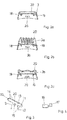
- FIG. 2 In the Fig. 2 are shown in longitudinal section different cap shapes.
- the Fig. 2a already shows in the Fig. 1 shown cap 3, this has a rounded upper end edge.
- the cap 3a according to the Fig. 2b has a comb-like structure and is therefore particularly suitable for the treatment of the scalp.
- the Fig. 2c shows a cap 3b with a wave-shaped edge, whereby the pressure on the skin can be selectively reinforced, so that when going back and forth of the cap 3b on the skin creates a massage effect.
- a further cap 9 which is a modification of the cap 3 according to Fig. 2a represents.
- two tongues 10, 11 join, which together form a platform 13 which is inclined relative to a base 12 of the cap 9.
- the top of the platform 13 forms a continuous Surface which can be placed on the skin and which is provided with ribs 14.
- This form is particularly suitable for connection to a vibrator 15. This is either preferably attached at an acute angle between the one tongue 11 and the base 12 of the cap 9 (dash-dotted) or in the head of the base 12 of the cap 9 (solid line). It would also be conceivable to accommodate one of the tongues 10, 11.
- the vibrator 15 is in the simplest case according to the Fig. 4 from an electric motor 16, on whose shaft an eccentric 17 is mounted.
- the orientation of the shaft in relation to the device is arbitrary. It is possible to align parallel to the upper edge of the cap. 9
- Fig. 2a to 2c can be found within the cap 3, 3a, 3b, two metallic contact pins 18, 19, wherein the one contact pin 18 is in electrical connection with the cap 3 and the other contact pin 19 is insulated from the cap 3, 3a, 3b.
- the caps 3, 3a, 3b are made of a conductive material or have at least a coating of a conductive material forming the second electrode 20. The first contact pin 18 is thus in communication with this material, while the second contact pin 19 is insulated therefrom.
- Fig. 7 schematically a circuit diagram is shown.
- the drive of the vibrator, so in the embodiment of the electric motor 16 is connected between the two contact pins 18, 19 in the cap 3, 9, while the first contact pin 18 is connected only to the second electrode 20 on the cap 3, 9.
- the base body 2 On the base body 2 are two counter pins 21, 22, which are connected via a switching device in the form of a changeover switch 29 with a voltage source 30 (batteries).
- the changeover switch is realized in the form of a transistor circuit which is controlled by a control device 31.
- the control device 31 contains an electronic memory in which a plurality of operating modes are stored. The operating modes are determined by the parameters (duration of treatment, polarization of the electrodes, connection of the vibrator). The user can select a specific mode by pressing the button 5, which is displayed in the display 6.
- a skin treatment consists of a first step, in which a cleansing cream is first applied and the device is operated in a first polarity, wherein the current flow causes pollutants to pass from the skin into the cleansing cream.
- This caps are used 3, which contain no vibrator, because the cream just should not be incorporated into the skin.
- a treatment cream is applied and the device 1 is operated in a second polarity so that the active ingredients can penetrate from the treatment cream into the skin.
- caps 9 are used, which have a vibrator 15, so that in addition to the current effect, which transports the active ingredients in the skin, also a Einmassage bin is present, with which the active ingredient is massaged into the skin.
- a vibrator 15 in addition to the current effect, which transports the active ingredients in the skin, also a Einmassage bin is present, with which the active ingredient is massaged into the skin.
- the Fig. 8 shows in cross section a device 40, which is particularly suitable for the treatment of cellulitis of large areas of skin.
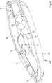
- a second electrode 20 On the underside of a flat housing 41 there is a second electrode 20 occupying almost the entire underside, which is placed on the skin surface to be treated. On the top there is a display 6 and a button 5 for selecting a treatment program.
- a first electrode 7 On the outer edge of the top of the housing 41 is circumferentially a first electrode 7, which is in contact with the device 40 holding the hand.
- a voltage source 30 in the form of batteries, and a vibrator 15, which consists of an electric motor 16 with an eccentric 17.
- the vibrator 15 is mounted centrally above the second electrode 20 by means of a socket not shown on the lower wall of the housing 41 and thus sets the wall together with the second electrode 20 in vibration when it is put into operation.
- connection of the electrodes 7, 20 of the electric motor 16 and the voltage source 30 corresponds to that in Fig. 7 however, the pins 18, 19; 21, 22 are replaced by continuous connections. The pins are not needed since the device 40 in this embodiment has no replaceable caps 3, 9 with second electrodes 20.
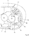
- the housing of the device 1 consists of two half-shells 70, 71, which are assembled to form a closed housing, wherein the bottom portion of the housing is substantially formed by an edge portion of one of the half-shells 70. In this edge, access to a slot 72 is accommodated in which rechargeable batteries 73 are used.
- the shaft 72 is formed by a circumferential ridge 74 on the edge portion of the half-shell 70. In the shaft 72, the batteries 73 are anti-parallel side by side.
- a half-shell-shaped housing cover 75 covers the shaft 72. For this purpose, it also has on its inside a circumferential counter-ridge 76 which is attached to the web 74 on the half-shell 70.
- the outer contour of the housing cover 75 is shaped such that a smooth transition to the outer contours of the half-shells 70, 71 is formed.
- a shaft cover 77 is further provided, which rests on the batteries 73 and to its inside a groove-shaped recess 78 and which has on its outer side a molding which forms a plug housing 79.
- the plug housing 79 abuts against the inside of the housing cover 75, so that in this way a holding force is exerted on the batteries 73 when the housing cover 75 with his counterpart 76 is attached to the circumferential ridge 74.
- the plug housing 79 is hollow and is open to the bottom of the manhole cover 77. On a wall of the plug housing 79 is a housing opening 80. In the plug housing 79, a connector board, not shown here with a USB connector socket is inserted such that the plug opening is located in front of the housing opening 80.
- the drive 90 of a vibrator is connected in series with the collector / emitter / path of a transistor 91.
- a control voltage is applied at the base 92 of the transistor 91. If this is the case, the transistor turns on, so that the motor has current flowing through it. If no voltage is present at the base 92, the transistor 91 blocks, so that the drive 90 is switched off.
- the switching voltage at the base is supplied by a control circuit which detects by means of a detector whether a current flows to the second electrode.
Landscapes
- Health & Medical Sciences (AREA)
- Life Sciences & Earth Sciences (AREA)
- Public Health (AREA)
- Animal Behavior & Ethology (AREA)
- General Health & Medical Sciences (AREA)
- Veterinary Medicine (AREA)
- Engineering & Computer Science (AREA)
- Biomedical Technology (AREA)
- Nuclear Medicine, Radiotherapy & Molecular Imaging (AREA)
- Radiology & Medical Imaging (AREA)
- Pain & Pain Management (AREA)
- Physical Education & Sports Medicine (AREA)
- Rehabilitation Therapy (AREA)
- Epidemiology (AREA)
- Biophysics (AREA)
- Bioinformatics & Cheminformatics (AREA)
- Dermatology (AREA)
- Plastic & Reconstructive Surgery (AREA)
- Oral & Maxillofacial Surgery (AREA)
- Medical Informatics (AREA)
- Anesthesiology (AREA)
- Heart & Thoracic Surgery (AREA)
- Hematology (AREA)
- Percussion Or Vibration Massage (AREA)
- Electrotherapy Devices (AREA)
- Radiation-Therapy Devices (AREA)
Abstract
Description
- Die Erfindung bezieht sich auf ein in einer Hand haltbares Gerät zur elektrisch unterstützten Hautbehandlung, aufweisend:
- Ein Gehäuse, das ausgebildet ist, um von einer Hand ergriffen zu werden,
- eine erste äußere Elektrode am Gehäuse, die in Kontakt zur Hand steht, wenn das Gerät vom Nutzer zum Gebrauch in der Hand gehalten wird, wobei an dem Gehäuse die erste äußere Elektrode vorhanden ist, eine zweite äußere Elektrode, die auf den zu behandelnden Hautbereich aufsetzbar ist, und eine elektrische Energiequelle im Gehäuse, deren Pole beim Betrieb des Gerätes mit den Elektroden in einer elektrischen Verbindung stehen, wobei die Energiequelle in dem Gehäuse angeordnet ist.
- Ein derartiges Gerät ist in der
WO 2005/087308 A1 beschrieben. Um das Gerät einzusetzen, nimmt der Nutzer es in die Hand und setzt eine als Elektrode fungierende Kappe auf die zu behandelnden Hautbereiche auf. Mit der ersten Elektrode wird ein elektrisch leitender Kontakt zur Hand und mit der zweiten Elektrode ein elektrisch leitender Kontakt zu dem zu behandelnden Hautbereich hergestellt. Da die beiden Elektroden an je einem Pol einer elektrischen Energiequelle angeschlossen sind, entsteht ein elektrischer Stromkreis, der den Körper des Nutzers mit einschließt, wobei je nach Polung ein positiver oder ein negativer elektrischer Strom von der Kappe in den zu behandelnden Hautbereich einfließt. - Dies kann dazu benutzt werden, die Wirkungsweise von Behandlungscremes bzw. Reinigungscremes zu erhöhen, da die Wirkstoffe einer Behandlungscreme mit dem elektrischen Strom in die Haut transportiert werden und bei einer entgegengesetzten Polung Schmutzstoffe aus der Haut in eine Reinigungscreme transportiert werden.
- Das Gerät ist weiterhin mit einer Vielzahl von auswechselbaren Kappen versehen, deren Form jeweils an die zu behandelnde Hautoberfläche angepasst ist. Es gibt eine erste Kappe mit einer relativ glatten Oberfläche, eine zweite Kappe, die kammartig gestaltet ist, die vor allem zur Behandlung der Kopfhaut eingesetzt werden kann, und eine dritte Kappe mit einer welligen Struktur, womit ein Massageeffekt verbunden ist. Mit dem Gerät werden gute Ergebnisse sowohl bei der Hautreinigung als auch bei der Einbringung von Wirkstoffen erzielt. Dies soll aber noch weiter effektiviert werden.
- Die Erfindung beruht somit auf der Aufgabe, die Wirkungsweise des Gerätes noch weiter zu verbessern.
- Zur Lösung der Aufgabe wird vorgeschlagen, dass die zweite Elektrode sich an einer Seite, nämlich der unteren Seite des Gehäuses, befindet und dass ein elektrisch betriebener Vibrator zentral oberhalb der zweiten Elektrode mittels eines Sockels an der unteren Wand des Gehäuses angebracht und derart ausgebildet ist, um die Wand zusammen mit der zweiten Elektrode in Schwingung zu versetzen, wenn er in Betrieb genommen wird.
- Ein solcher Vibrator setzt das Gerät in eine schwingende Bewegung, so dass beim Betrieb des Gerätes ein verstärkter Massageeffekt auf der zu behandelnden Haut entsteht, wodurch die Hautporen geweitet werden und ein noch besserer Übergang der Schmutzstoffe aus der Haut bzw. der Wirkstoffe in die Haut realisiert wird.
- Der Massageeffekt ist besonders ausgeprägt, wenn der Vibrator in der Nähe der zweiten äußeren Elektrode angebracht ist, weil dann der Bereich des Gerätes besonders stark vibriert, der sich an dem zu behandelnden Hautbereich befindet.
- Vorzugsweise wird die Erfindung bei einem Gerät eingesetzt, bei dem
das Gehäuse ein flaches Gehäuse mit einer Oberseite und einer Unterseite ist, die von einer unteren Wand gebildet ist,
die zweite äußere Elektrode sich an der Unterseite des Gehäuses befindet, wobei sie fast die gesamte Unterseite einnimmt,
die erste Elektrode sich umlaufend am Außenrand der Oberseite des Gehäuses befindet und
sich auf der Oberseite ein Display und eine Taste zur Auswahl eines Behandlungsprogramms befinden. - Bei der Energiequelle kann es sich um Batterien oder auch um Akkus handeln, die in ein Fach des Basiskörpers eingelegt werden. Soweit für das Gerät Akkus vorgesehen sein sollen, ist es denkbar, zu dem Gerät auch ein Ladegerät zu liefern, mit dem die Akkus im Gerät aufgeladen werden können.
- Da - wie oben erläutert - das Gerät vorsieht, dass die Polarität der Elektroden austauschbar ist, hat dies zur Folge, dass auch die Polarität der Stromversorgung des Vibrators sich umkehrt. Daher muss der Vibrator einen elektrischen Antrieb besitzen, der unempfindlich ist gegenüber einer Vertauschung der Polarität. Im einfachsten Fall handelt es sich bei dem Vibrator um einen elektrischen Motor, an dessen Welle ein Excenter befestigt ist. Denkbar wären aber auch Schwingungserreger, bei denen eine Masse durch Elektromagnete in schneller Folge mal in die eine, mal in die andere Richtung gezogen wird.
- Um den Aufbau des Gerätes einfach zu halten, ist vorgesehen, dass eine vom Nutzer des Gerätes einstellbare Schalteinrichtung im Basiskörper vorhanden ist, die die elektrischen Verbindungen der Energiequelle zu den Elektroden herstellt, und dass auch der Vibrator über die Schalteinrichtung mit der elektrischen Energiequelle verbunden ist. Es liegt somit eine gemeinsame Energiequelle für die Elektrode und den Vibrator vor.
- Vorzugsweise ist die Schalteinrichtung mit einem elektronischen Speicher versehen, in dem die Parameter von auszuwählenden Betriebszuständen gespeichert sind, die vom Benutzer mittels einer Taste auswählbar sind, wobei einer der Parameter sich auf die Polarität der Elektroden bezieht, und wobei der Vibrator von der Art ist, dass er unabhängig von der Polarität der angelegten Spannung arbeitet.
- Damit die Batterien möglichst selten geladen werden müssen, muss dafür gesorgt werden, dass der Stromverbrauch des Gerätes möglichst minimiert wird. Dies ist insbesondere dann der Fall, wenn das Gerät mit einem Vibrator versehen ist, der die zweite Elektrode, die auf die zu behandelnde Hautfläche aufgesetzt wird, in eine rüttelnde Bewegung versetzt. Um bei einem solchen Gerät den Stromverbrauch zu minimieren, sieht die Erfindung vor, dass eine Einrichtung zum Detektieren eines Stromflusses durch die zweite Elektrode, ein Schalter in der Verbindung des Antriebs des Vibrators zu Batterien und eine Steuerung vorgesehen sind, wobei die Steuerung so eingerichtet ist, dass der Schalter nur dann geschlossen ist, wenn durch die zweite Elektrode ein Strom fließt.
- Mit anderen Worten, der Vibrator wird nur dann eingeschaltet, wenn die zweite Elektrode auf die zu behandelnde Hautfläche aufgesetzt ist und durch sie ein Strom durch die Haut fließt. Dieser Stromfluss wird detektiert und von einer Steuerung genutzt, um den Schalter zu betätigen. Die Einrichtung lässt sich elektronisch realisieren. Dies bedeutet, dass der Schalter als ein Transistor ausgeführt ist.
- Weiterhin ist vorgesehen, dass das Gerät wiederaufladbare Batterien, deren Pole beim Betrieb des Gerätes mit den Elektroden in einer elektrischen Verbindung stehen, aufweist. Die Batterien sind in einem Schacht untergebracht, der von einem schalenförmigen Gehäusedeckel überdeckt ist, dessen Außenseite einen Abschnitt der Außenfläche des Gerätegehäuses bildet. Weiterhin ist eine Ladeschaltung vorgesehen. Der Schacht wird von einer entfernbaren Schachtabdeckung abgedeckt, deren Innenseite zu den Batterien im Schacht weist und auf deren Außenseite eine wenigstens 2-polige Steckerbuchse angeordnet ist, die mit der Ladeschaltung in Verbindung steht. Die Schachtabdeckung befindet sich innerhalb des Gehäusedeckels.
- Die Steckerbuchse ist vorzugsweise eine Steckerbuchse nach dem USB Standard.
- Im Folgenden soll anhand eines Ausführungsbeispiels, dargestellt in der
Fig. 8 , die Erfindung näher erläutert werden. Dabei beziehen sich die zusätzlichenFigur 7 und16 auf die mögliche Verschaltung der Elektroden und dieFig. 4 auf den Vibrator. Die zusätzlicheFig. 15 bezieht sich auf eine Aufnahme von Akkumulatoren im Gehäuse. Die Ausführungen nach denFig. 1-3 sind für sich genommen nicht Gegenstand der Ansprüche. Es zeigen: - Fig. 1 a, b, c
- die Ansichten eines Gerätes, wobei als Kappe eine gerundete Struktur vorgesehen ist,
- Fig.2 a, b, c
- verschiedene Kappenformen zur Verwendung mit dem Gerät,
- Fig. 3
- den Querschnitt einer Kappenform, die für den Betrieb mit einem Vibrator besonders geeignet ist,
- Fig. 4
- einen Motor mit einem Excenter,
- Fig. 7
- einen Schaltkreis zum Betrieb des Gerätes,
- Fig. 8
- eine Ausführung des erfindungsgemäßen Gerätes,
- Fig. 15
- einen Schnitt durch den Batterieschacht des Gerätes und
- Fig. 16
- eine Schaltung für die Steuerung eines Vibrationsmotors.
- Zunächst wird auf die
Fig. 1 Bezug genommen. Wie die drei Ansichten zeigen, ist das Gerät 1 etwa handtellergroß und hat eine rechteckige, flache Form. Es besteht aus einem Basiskörper 2 und einer darauf aufgesteckten Kappe 3. An der unteren kurzen Seite des Basiskörpers 2 befindet sich ein Fach 4 zur Aufnahme von Batterien, die als Energiequelle zum Betrieb des Gerätes 1 fungieren. - An der gegenüberliegenden oberen, kurzen Seite des Basiskörpers 2, die nicht so breit wie die untere Seite ist, ist die auswechselbare Kappe 3 aufgesteckt. Auf der Vorderseite des Basiskörpers 2 ist eine Taste 5 zur Auswahl eines Behandlungsprogramms angeordnet, wobei das ausgewählte Behandlungsprogramm in einem darüber liegenden Display 6 angezeigt wird. Auf der Rückseite befindet sich eine großflächige erste Elektrode 7 und darüber ein Druckknopf 8 zur Auslösung einer Raste, mit der die Kappe 3 am Basiskörper 2 gehalten wird.
- In der
Fig. 2 sind im Längsschnitt verschiedene Kappenformen dargestellt. DieFig. 2a zeigt die schon in derFig. 1 dargestellte Kappe 3, diese hat eine gerundete obere Abschlusskante. - Die Kappe 3a gemäß der
Fig. 2b hat eine kammartige Struktur und eignet sich daher besonders zur Behandlung der Kopfhaut. DieFig. 2c zeigt eine Kappe 3b mit einer wellenförmig ausgeführten Kante, wodurch der Druck auf die Haut punktuell verstärkt werden kann, so dass beim Hin- und Hergehen der Kappe 3b auf der Haut ein Massageeffekt entsteht. - Gemäß der
Fig. 3 ist im Querschnitt eine weitere Kappe 9 dargestellt, die eine Abwandlung der Kappe 3 gemäßFig. 2a darstellt. An der oberen Kante der Kappe 9 schließen sich zwei Zungen 10, 11 an, die zusammen eine gegenüber einer Basis 12 der Kappe 9 schräg gestellte Plattform 13 bilden. Die Oberseite der Plattform 13 bildet eine durchgehende Fläche, die auf die Haut aufsetzbar ist und die mit Rippen 14 versehen ist. - Diese Form ist besonders geeignet zur Verbindung mit einem Vibrator 15. Dieser ist entweder vorzugsweise im spitzen Winkel zwischen der einen Zunge 11 und der Basis 12 der Kappe 9 angebracht (strichpunktiert) oder im Kopf der Basis 12 der Kappe 9 (durchgehende Linie). Denkbar wäre auch eine Unterbringung in einer der Zungen 10, 11.
- Der Vibrator 15 besteht im einfachsten Fall gemäß der
Fig. 4 aus einem Elektromotor 16, an dessen Welle ein Excenter 17 angebracht ist. Die Ausrichtung der Welle im Bezug zum Gerät ist beliebig. Möglich ist eine Ausrichtung parallel zur oberen Kante der Kappe 9. - Wie man den
Fig. 2a bis 2c entnehmen kann, befinden sich innerhalb der Kappe 3, 3a, 3b zwei metallische Kontaktstifte 18, 19, wobei der eine Kontaktstift 18 mit der Kappe 3 in elektrischer Verbindung steht und der andere Kontaktstift 19 isoliert gegenüber der Kappe 3, 3a, 3b ist. Die Kappen 3, 3a, 3b bestehen aus einem leitfähigen Material oder besitzen zumindest einen Überzug aus einem leitfähigen Material, das die zweite Elektrode 20 bildet. Der erste Kontaktstift 18 steht somit in Verbindung zu diesem Material, während der zweite Kontaktstift 19 dazu isoliert ist. - In der
Fig. 7 ist schematisch ein Schaltplan dargestellt. Der Antrieb des Vibrators, also im Ausführungsbeispiel der Elektromotor 16, ist zwischen den beiden Kontaktstiften 18, 19 in der Kappe 3, 9 geschaltet, während der erste Kontaktstift 18 nur mit der zweiten Elektrode 20 an der Kappe 3, 9 verbunden ist. - Am Basiskörper 2 befinden sich zwei Gegenstifte 21, 22, die über eine Schalteinrichtung in Form eines Wechselschalters 29 mit einer Spannungsquelle 30 (Batterien) verbunden sind. Der Gegenstift 21, der mit dem isolierten Kontaktstift 18 in der Kappe 3, 9 in Kontakt tritt, hat eine Verbindung zur ersten Elektrode 7 am Basiskörper 2.
- Wird nun die Kappe 3, 9 - wie in der
Fig. 7 angedeutet - auf den Basiskörper 2 aufgesteckt (eine Codierung verhindert dabei eine Vertauschung der Kontakte), entsteht ein erster Stromkreis, bestehend aus der Spannungsquelle 30 und dem Elektromotor 16, der über die beiden Stiftpaare verläuft, sowie im Betrieb ein zweiter Stromkreis, der über den ersten Kontakt der zweiten Elektrode 20 über den Körper des Nutzers zur ersten Elektrode 7 und zurück zur Spannungsquelle 30 verläuft. - Der Wechselschalter ist in Form einer Transistorschaltung realisiert, die von einer Steuereinrichtung 31 angesteuert wird. Die Steuereinrichtung 31 enthält einen elektronischen Speicher, in dem mehrere Betriebsarten abgespeichert sind. Die Betriebsarten werden durch die Parameter (Dauer der Behandlung, Polarisierung der Elektroden, Zuschaltung des Vibrators) bestimmt. Der Nutzer kann durch Betätigung der Taste 5 eine bestimmte Betriebsart auswählen, die in dem Display 6 angezeigt wird.
- Eine Hautbehandlung besteht in der Regel aus einem ersten Schritt, bei dem zunächst eine Reinigungscreme aufgebracht wird und das Gerät in einer ersten Polung betrieben wird, wobei durch den Stromfluss Schadstoffe aus der Haut in die Reinigungscreme übergehen. Hierbei werden Kappen 3 genutzt, die keinen Vibrator enthalten, weil die Creme gerade nicht in die Haut eingearbeitet werden soll.
- In einem zweiten Schritt, nachdem die Reinigungscreme entfernt wurde, wird eine Behandlungscreme aufgetragen und das Gerät 1 in einer zweiten Polung betrieben, so dass die Wirkstoffe aus der Behandlungscreme in die Haut eindringen können. Bei dieser Vorgehensweise werden Kappen 9 benutzt, die einen Vibrator 15 aufweisen, so dass neben dem Stromeffekt, der die Wirkstoffe in die Haut transportiert, auch ein Einmassageeffekt vorhanden ist, mit dem der Wirkstoff in die Haut einmassiert wird. Neben der erhöhten Effektivität wird auch ein angenehmes Behandlungsgefühl erzeugt, da eine vibrierende Massage vom Nutzer als angenehm empfunden wird.
- Die
Fig. 8 zeigt im Querschnitt ein Gerät 40, das insbesondere zur Zellulitis-Behandlung von großen Hautflächen geeignet ist. - An der Unterseite eines flachen Gehäuses 41 befindet sich eine fast die gesamte Unterseite einnehmende zweite Elektrode 20, die auf die zu behandelnde Hautfläche aufgesetzt wird. Auf der Oberseite befinden sich ein Display 6 und eine Taste 5 zur Auswahl eines Behandlungsprogramms.
- Am Außenrand der Oberseite des Gehäuses 41 befindet sich umlaufend eine erste Elektrode 7, die in Kontakt zu der das Gerät 40 haltenden Hand steht. Innerhalb des Gehäuses 41 befinden sich eine Spannungsquelle 30 in Form von Batterien, sowie ein Vibrator 15, der aus einem Elektromotor 16 mit einem Excenter 17 besteht. Der Vibrator 15 ist zentral oberhalb der zweiten Elektrode 20 mittels eines nicht näher dargestellten Sockels an der unteren Wand des Gehäuses 41 angebracht und setzt somit die Wand zusammen mit der zweiten Elektrode 20 in Schwingung, wenn er in Betrieb genommen wird.
- Die Verschaltung der Elektroden 7, 20 des Elektromotors 16 und der Spannungsquelle 30 entspricht der, die in
Fig. 7 gezeigt ist, wobei allerdings die Stifte 18, 19; 21, 22 durch durchgehende Verbindungen ersetzt sind. Die Stifte werden nicht benötigt, da das Gerät 40 in dieser Ausführung keine auswechselbaren Kappen 3, 9 mit zweiten Elektroden 20 besitzt. - Wie der
Fig. 15 entnommen werden kann, besteht das Gehäuse des Gerätes 1 aus zwei Halbschalen 70, 71, die zu einem geschlossenen Gehäuse zusammengesetzt werden, wobei der Bodenbereich des Gehäuses im Wesentlichen von einem Randabschnitt einer der Halbschalen 70 gebildet wird. In diesem Rand ist der Zugang zu einem Schacht 72 untergebracht, in dem wiederaufladbare Batterien 73 eingesetzt werden. Der Schacht 72 wird von einem umlaufenden Steg 74 auf dem Randabschnitt der Halbschale 70 gebildet. In dem Schacht 72 liegen die Batterien 73 antiparallel nebeneinander. - Ein halbschalenförmiger Gehäusedeckel 75 deckt den Schacht 72 ab. Dazu besitzt er an seiner Innenseite ebenfalls einen umlaufenden Gegensteg 76, der auf den Steg 74 an der Halbschale 70 aufgesteckt wird. Die Außenkontur des Gehäusedeckels 75 ist dabei so geformt, dass sich ein glatter Übergang zu den Außenkonturen der Halbschalen 70, 71 bildet.
- In dem Schacht 72 selbst ist weiterhin eine Schachtabdeckung 77 vorgesehen, die auf den Batterien 73 aufliegt und dazu an ihrer Innenseite eine rinnenförmige Vertiefung 78 aufweist und die an ihrer Außenseite eine Ausformung besitzt, die ein Steckergehäuse 79 bildet. Das Steckergehäuse 79 liegt an der Innenseite des Gehäusedeckels 75 an, so dass auf diese Weise eine Haltekraft auf die Batterien 73 ausgeübt wird, wenn der Gehäusedeckel 75 mit seinem Gegensteg 76 auf den umlaufenden Steg 74 aufgesteckt ist.
- Das Steckergehäuse 79 ist hohl ausgeführt und ist zur Unterseite der Schachtabdeckung 77 hin offen. An einer Wand des Steckergehäuses 79 befindet sich eine Gehäuseöffnung 80. In das Steckergehäuse 79 ist eine hier nicht gezeigte Steckerplatine mit einer USB-Steckerbuchse derart eingesetzt, dass die Steckeröffnung sich vor der Gehäuseöffnung 80 befindet.
- Wie man der
Fig. 16 entnehmen kann, ist der Antrieb 90 eines Vibrators in Reihe geschaltet mit der Kollektor/Emitter/Strecke eines Transistors 91. An der Basis 92 des Transistors 91 wird eine Steuerspannung angelegt. Liegt diese vor, schaltet der Transistor durch, so dass der Motor Strom durchflossen ist. Liegt keine Spannung an der Basis 92 an, sperrt der Transistor 91, so dass der Antrieb 90 abgeschaltet wird. - Die Schaltspannung an der Basis wird von einer Steuerschaltung geliefert, die mittels eines Detektors feststellt, ob ein Strom zur zweiten Elektrode fließt.
-
- 1
- Gerät
- 2
- Basiskörper
- 3
- Kappe
- 3a
- Kappe
- 3b
- Kappe
- 4
- Fach
- 5
- Taste
- 6
- Display
- 7
- erste Elektrode
- 8
- Druckknopf
- 9
- Kappe
- 10
- Zunge
- 11
- Zunge
- 12
- Basis einer Kappe
- 13
- Plattform
- 14
- Rippen
- 15
- Vibrator
- 16
- Elektromotor
- 17
- Excenter
- 18
- Kontaktstift
- 19
- Kontaktstift
- 20
- zweite Elektrode
- 21
- Gegenstift
- 22
- Gegenstift
- 26
- Schlitz
- 29
- Wechselschalter
- 30
- Spannungsquelle
- 40
- Gerät
- 41
- Gehäuse
- 70
- Halbschale
- 71
- Halbschale
- 72
- Schacht
- 73
- Batterien
- 74
- Steg
- 75
- Gehäusedeckel
- 76
- Gegensteg
- 77
- Schachtabdeckung
- 78
- Vertiefung
- 79
- Steckergehäuse
- 80
- Gehäuseöffnung
- 90
- Antrieb
- 91
- Transistor
- 92
- Basis
Claims (7)
- In einer Hand haltbares Gerät zur elektrisch unterstützten Hautbehandlung, aufweisend:Ein Gehäuse (41), das ausgebildet ist, um von einer Hand ergriffen zu werden,eine erste äußere Elektrode (7) am Gehäuse (41), die in Kontakt zur Hand steht, wenn das Gerät vom Nutzer zum Gebrauch in der Hand gehalten wird, wobei an dem Gehäuse (41) die erste äußere Elektrode (7) vorhanden ist,eine zweite äußere Elektrode (20), die auf den zu behandelnden Hautbereich aufsetzbar ist, undeine elektrische Energiequelle im Gehäuse (41), deren Pole beim Betrieb des Gerätes mit den Elektroden (7, 20) in einer elektrischen Verbindung stehen, wobei die Energiequelle in dem Gehäuse angeordnet ist,dadurch gekennzeichnet, dassdie zweite Elektrode (20) sich an einer Seite, nämlich der unteren Seite des Gehäuses (41), befindet und dassein elektrisch betriebener Vibrator (15) zentral oberhalb der zweiten Elektrode (20) mittels eines Sockels an der unteren Wand des Gehäuses (41) angebracht und derart ausgebildet ist, um die Wand zusammen mit der zweiten Elektrode (20) in Schwingung zu versetzen, wenn er in Betrieb genommen wird, so dass beim Betrieb des Gerätes ein verstärkter Massageeffekt auf der zu behandelnden Haut entsteht, wodurch die Hautporen geweitet werden.
- Gerät nach Anspruch 1, dadurch gekennzeichnet, dass der Vibrator (15) in der Nähe der zweiten äußeren Elektrode (20) angebracht ist.
- Gerät nach Anspruch 1 oder 2 dadurch gekennzeichnet,
dass das Gehäuse (41) ein flaches Gehäuse mit einer Oberseite und einer Unterseite ist, die von einer unteren Wand gebildet ist,
dass die zweite äußere Elektrode (20) sich an der Unterseite des Gehäuses befindet, wobei sie fast die gesamte Unterseite einnimmt,
dass die erste Elektrode (7) sich umlaufend am Außenrand der Oberseite des Gehäuses (41) befindet und
dass sich auf der Oberseite ein Display (6) und eine Taste (5) zur Auswahl eines Behandlungsprogramms befinden. - Gerät nach einem der vorhergehenden Ansprüche, dadurch gekennzeichnet, dass der Vibrator (15) aus einem elektrischen Motor (16) besteht, an dessen Welle ein Excenter (17) befestigt ist.
- Gerät nach einem der vorhergehenden Ansprüche, dadurch gekennzeichnet, dass eine vom Nutzer des Gerätes einstellbare Schalteinrichtung im Basiskörper (2) vorhanden ist, die die elektrischen Verbindungen der Energiequelle zu den Elektroden (7, 20) herstellt, dass auch der Vibrator (15) über die Schalteinrichtung mit der elektrischen Energiequelle verbunden ist, dass die Schalteinrichtung mit einem elektronischen Speicher versehen ist, in dem die Parameter von auszuwählenden Betriebszuständen gespeichert sind, die vom Benutzer mittels einer Taste (5) auswählbar sind, wobei einer der Parameter sich auf die Polarität der Elektroden bezieht, und dass der Vibrator (15) von der Art ist, dass er unabhängig von der Polarität der angelegten Spannung arbeitet.
- Gerät nach einem der vorhergehenden Ansprüche, dadurch gekennzeichnet, dass eine Einrichtung zum Detektieren eines Stromflusses durch die zweite Elektrode (20), ein Schalter in der Verbindung des Antriebs des Vibrators zu Batterien und eine Steuerung vorgesehen sind, wobei die Steuerung so eingerichtet ist, dass der Schalter nur dann geschlossen ist, wenn durch die zweite Elektrode (20) ein Strom fließt.
- Gerät nach einem der vorhergehenden Ansprüche, dadurch gekennzeichnet, dass es wiederaufladbare Batterien (73) aufweist, deren Pole beim Betrieb des Gerätes mit den Elektroden in einer elektrischen Verbindung stehen,
und einen Schacht (72) zur Aufnahme der Batterien besitzt, der von einem schalenförmigen Gehäusedeckel (75) überdeckt ist, dessen Außenseite einen Abschnitt der Außenfläche des Gerätegehäuses bildet,
wobei eine Ladeschaltung vorgesehen ist, und
der Schacht (72) von einer entfernbaren Schachtabdeckung (77) abgedeckt ist, deren Innenseite zu den Batterien (73) im Schacht weist und auf deren Außenseite eine wenigstens 2-polige Steckerbuchse angeordnet ist, und
sich die Schachtabdeckung (77) innerhalb des Gehäusedeckels (75) befindet.
Priority Applications (5)
| Application Number | Priority Date | Filing Date | Title |
|---|---|---|---|
| SI201331895T SI3524317T1 (sl) | 2012-01-16 | 2013-01-16 | V roki držeča naprava za električno podprto obdelavo kože |
| RS20210758A RS61992B1 (sr) | 2012-01-16 | 2013-01-16 | Električni uređaj za tretiranje kože koji se drži u jednoj ruci |
| SM20210349T SMT202100349T1 (it) | 2012-01-16 | 2013-01-16 | Strumento tenibile in una mano per il trattamento dermatologico assistito elettricamente |
| PL19164931T PL3524317T3 (pl) | 2012-01-16 | 2013-01-16 | Ręczne urządzenie do wspomaganej elektrycznie pielęgnacji skóry |
| HRP20210954TT HRP20210954T1 (hr) | 2012-01-16 | 2021-06-14 | Uređaj za električno potpomognuti tretman kože, koji se može držati u jednoj ruci |
Applications Claiming Priority (4)
| Application Number | Priority Date | Filing Date | Title |
|---|---|---|---|
| DE102012000563 | 2012-01-16 | ||
| DE201210009514 DE102012009514A1 (de) | 2012-05-14 | 2012-05-14 | In einer Hand haltbares Gerät zur elektrisch unterstützten Hautbehandlung |
| EP13710970.8A EP2804663B1 (de) | 2012-01-16 | 2013-01-16 | In einer hand haltbares gerät zur elektrisch unterstützten hautbehandlung |
| PCT/EP2013/000112 WO2013107635A2 (de) | 2012-01-16 | 2013-01-16 | In einer hand haltbares gerät zur elektrisch unterstützten hautbehandlung |
Related Parent Applications (1)
| Application Number | Title | Priority Date | Filing Date |
|---|---|---|---|
| EP13710970.8A Division EP2804663B1 (de) | 2012-01-16 | 2013-01-16 | In einer hand haltbares gerät zur elektrisch unterstützten hautbehandlung |
Publications (2)
| Publication Number | Publication Date |
|---|---|
| EP3524317A1 true EP3524317A1 (de) | 2019-08-14 |
| EP3524317B1 EP3524317B1 (de) | 2021-03-24 |
Family
ID=47913364
Family Applications (2)
| Application Number | Title | Priority Date | Filing Date |
|---|---|---|---|
| EP19164931.8A Active EP3524317B1 (de) | 2012-01-16 | 2013-01-16 | In einer hand haltbares gerät zur elektrisch unterstützten hautbehandlung |
| EP13710970.8A Active EP2804663B1 (de) | 2012-01-16 | 2013-01-16 | In einer hand haltbares gerät zur elektrisch unterstützten hautbehandlung |
Family Applications After (1)
| Application Number | Title | Priority Date | Filing Date |
|---|---|---|---|
| EP13710970.8A Active EP2804663B1 (de) | 2012-01-16 | 2013-01-16 | In einer hand haltbares gerät zur elektrisch unterstützten hautbehandlung |
Country Status (28)
| Country | Link |
|---|---|
| US (2) | US10124165B2 (de) |
| EP (2) | EP3524317B1 (de) |
| JP (2) | JP6217048B2 (de) |
| KR (2) | KR101850129B1 (de) |
| CN (2) | CN104302352B (de) |
| AU (1) | AU2013211244B2 (de) |
| BR (1) | BR112014017355B1 (de) |
| CA (1) | CA2861238C (de) |
| CY (2) | CY1121904T1 (de) |
| DK (2) | DK2804663T3 (de) |
| ES (2) | ES2731955T3 (de) |
| HR (2) | HRP20191149T1 (de) |
| HU (2) | HUE043910T2 (de) |
| IL (1) | IL233505B (de) |
| LT (2) | LT2804663T (de) |
| MX (2) | MX382178B (de) |
| MY (1) | MY165900A (de) |
| NZ (2) | NZ719712A (de) |
| PH (1) | PH12014501597A1 (de) |
| PL (2) | PL2804663T3 (de) |
| PT (2) | PT3524317T (de) |
| RS (2) | RS61992B1 (de) |
| RU (2) | RU2645637C2 (de) |
| SG (1) | SG11201403906XA (de) |
| SI (2) | SI2804663T1 (de) |
| SM (2) | SMT201900374T1 (de) |
| WO (1) | WO2013107635A2 (de) |
| ZA (1) | ZA201405064B (de) |
Families Citing this family (20)
| Publication number | Priority date | Publication date | Assignee | Title |
|---|---|---|---|---|
| US10518097B2 (en) * | 2013-12-30 | 2019-12-31 | L'oreal | Workpiece with integrated battery |
| CA156468S (en) * | 2014-05-12 | 2015-01-27 | Ambient Therapeutics Inc | Personal cooling device |
| FR3020956B1 (fr) | 2014-05-19 | 2021-09-24 | Commissariat Energie Atomique | Dispositif medical cutane comprenant un moyen de controle amovible du type connecteur electrique. |
| JP6218039B2 (ja) * | 2014-05-29 | 2017-10-25 | パナソニックIpマネジメント株式会社 | 美容装置 |
| US20180126183A1 (en) * | 2015-05-29 | 2018-05-10 | Koninklijke Philips N.V. | A device for treating skin using non-thermal plasma |
| USD890941S1 (en) * | 2017-08-08 | 2020-07-21 | Reckitt Benckiser Health Limited | Skin treatment apparatus with roller |
| DE102017123809B4 (de) * | 2017-10-12 | 2025-10-30 | Swiss Spa System Ltd. | In einer Hand haltbares Gerät zur elektrisch unterstützten Hautbehandlung, Zusatzteil für dieses Gerät und Blister für dieses Zusatzteil |
| US11318307B2 (en) | 2018-01-03 | 2022-05-03 | Nse Products, Inc. | Fingertip mounted microcurrent device for skin |
| KR102106783B1 (ko) * | 2018-03-26 | 2020-05-06 | 트라이캠테크놀로지주식회사 | 전기 자극 장치 |
| CN108635664A (zh) * | 2018-05-10 | 2018-10-12 | 广州魔震电子科技有限公司 | 带电流的导入仪及护肤方法 |
| JP1635235S (de) * | 2018-07-04 | 2019-07-01 | ||
| JP7291703B2 (ja) * | 2018-07-27 | 2023-06-15 | ヤーマン株式会社 | 美容装置 |
| KR102135452B1 (ko) * | 2018-11-07 | 2020-07-17 | 주식회사 웨이브온 | 피부 접촉용 헤드 및 그를 이용한 휴대용 진동 장치 |
| US11730668B2 (en) | 2020-06-29 | 2023-08-22 | Therabody, Inc. | Vibrating therapy system and device |
| WO2022006086A1 (en) | 2020-06-29 | 2022-01-06 | Theragun, Inc. | Vibration therapy system and device |
| US11564863B2 (en) | 2020-06-29 | 2023-01-31 | Therabody, Inc. | Cooling attachment module for facial treatment device |
| TWM608619U (zh) * | 2020-11-12 | 2021-03-01 | 碧波庭國際有限公司 | 易於組裝的按摩棒結構 |
| USD976431S1 (en) | 2021-03-02 | 2023-01-24 | Therabody, Inc. | Facial treatment device |
| USD1004793S1 (en) | 2021-03-02 | 2023-11-14 | Therabody, Inc. | Facial treatment device |
| TWI828522B (zh) * | 2022-01-24 | 2024-01-01 | 鄭煜彬 | 手持式治療裝置 |
Citations (4)
| Publication number | Priority date | Publication date | Assignee | Title |
|---|---|---|---|---|
| US6385487B1 (en) * | 1996-05-08 | 2002-05-07 | Biophoretic Therapeutic Systems, Llc | Methods for electrokinetic delivery of medicaments |
| WO2005087308A1 (en) | 2004-02-12 | 2005-09-22 | Proventure (Far East) Limited | Skin/hair treatment method and system |
| EP2277585A2 (de) * | 1998-09-15 | 2011-01-26 | Biophoretic Therapeutic Systems, LLC | Elektroden zur iontophoretischen Verabreichung von Medikamenten |
| EP2384707A1 (de) * | 2010-05-06 | 2011-11-09 | Braun GmbH | Vorrichtung zur Zungenreinigung |
Family Cites Families (33)
| Publication number | Priority date | Publication date | Assignee | Title |
|---|---|---|---|---|
| CN2101489U (zh) * | 1991-04-25 | 1992-04-15 | 冉春风 | 一种偏心振动按摩器 |
| US5279284A (en) * | 1991-10-11 | 1994-01-18 | Frontier, Inc. | Skin stimulation device |
| JPH08252329A (ja) * | 1995-03-16 | 1996-10-01 | Advance Co Ltd | イオントフォレーゼ用インタフェース |
| US5925002A (en) * | 1995-09-22 | 1999-07-20 | Hwe, Inc. | Hand-held vibratory massager |
| US5607461A (en) * | 1995-10-20 | 1997-03-04 | Nexmed, Inc. | Apparatus and method for delivering electrical stimulus to tissue |
| US5676648A (en) * | 1996-05-08 | 1997-10-14 | The Aps Organization, Llp | Iontophoretic drug delivery apparatus and method for use |
| US6119038A (en) | 1998-11-20 | 2000-09-12 | Proventure, Llc | Handheld skin treatment system and method |
| KR100293459B1 (ko) * | 1998-12-07 | 2001-11-22 | 황현배 | 휴대용피부미용기기의제어방법및제어장치 |
| KR200219490Y1 (ko) * | 2000-10-31 | 2001-04-02 | 이양희 | 피부부착용 진동 마사지기 |
| US7496401B2 (en) * | 2001-04-06 | 2009-02-24 | Mattioli Engineering Ltd | Method and apparatus for skin absorption enhancement and transdermal drug delivery |
| US6980854B2 (en) * | 2001-04-06 | 2005-12-27 | Mattioli Engineering Ltd. | Method and apparatus for skin absorption enhancement and transdermal drug delivery of lidocaine and/or other drugs |
| US7083580B2 (en) * | 2001-04-06 | 2006-08-01 | Mattioli Engineering Ltd. | Method and apparatus for skin absorption enhancement and transdermal drug delivery |
| US20030164382A1 (en) * | 2002-02-27 | 2003-09-04 | Guy Thompson | Massage applicator for cosmetic compositions |
| US6766199B2 (en) * | 2002-10-10 | 2004-07-20 | Proventure (Far East), Limited | Skin/hair treatment method and system |
| US7228184B2 (en) * | 2003-02-22 | 2007-06-05 | Chester Heath | Viral-inhibiting method |
| RU2346709C2 (ru) * | 2003-06-13 | 2009-02-20 | Панасоник Электрик Уорк Ко., Лтд. | Устройство для ухода за кожей с использованием сонофореза |
| US20050234516A1 (en) * | 2004-02-16 | 2005-10-20 | Gueret Jean-Louis H | Treatment kit, composite structure, electric exciter, and cosmetic treatment method |
| JP4592329B2 (ja) * | 2004-05-24 | 2010-12-01 | 九州日立マクセル株式会社 | イオン導入器 |
| JP4668008B2 (ja) * | 2004-08-26 | 2011-04-13 | 株式会社資生堂 | 圧電部材を用いたイオン導入器 |
| CN2868326Y (zh) * | 2005-01-10 | 2007-02-14 | 上海竞骏工贸有限公司 | 量子洁肤美容仪 |
| JP2007037969A (ja) * | 2005-05-11 | 2007-02-15 | Beauty Clinical:Kk | 美容装置 |
| JP4744968B2 (ja) * | 2005-07-28 | 2011-08-10 | ヤーマン株式会社 | トリートメント装置 |
| US8874205B2 (en) * | 2009-03-20 | 2014-10-28 | ElectroCore, LLC | Device and methods for non-invasive electrical stimulation and their use for vagal nerve stimulation |
| KR100721794B1 (ko) * | 2006-02-13 | 2007-05-25 | 임수향 | 휴대용 통합 피부 미용장치 |
| US7495895B2 (en) * | 2006-04-19 | 2009-02-24 | Carnevali Jeffrey D | Protective cover for device having touch screen |
| US8700176B2 (en) * | 2006-07-27 | 2014-04-15 | Pollogen Ltd. | Apparatus and method for non-invasive treatment of skin tissue |
| CN201022903Y (zh) * | 2007-04-28 | 2008-02-20 | 吴琦 | 按摩热敷器 |
| JP5629586B2 (ja) * | 2008-02-20 | 2014-11-19 | シネロン メディカル リミテッド | 個人使用のための皮膚トリートメント装置及びこれを使用する方法 |
| US20090318852A1 (en) * | 2008-06-18 | 2009-12-24 | Jenu Biosciences, Inc. | Ultrasound based cosmetic therapy method and apparatus |
| JP4901818B2 (ja) * | 2008-07-10 | 2012-03-21 | 健康コーポレーション株式会社 | イオン導入機能付き超音波美容器 |
| US8821421B2 (en) * | 2009-08-26 | 2014-09-02 | Jj Acquisition, Llc | Massage device with flexible substructure |
| US8761874B2 (en) * | 2009-10-28 | 2014-06-24 | James M. Mantle | Electro-optical tissue stimulator and method of use |
| US10252051B2 (en) * | 2010-07-01 | 2019-04-09 | Thomas Nichols | Handheld facial massage and light therapy device |
-
2013
- 2013-01-16 ES ES13710970T patent/ES2731955T3/es active Active
- 2013-01-16 SG SG11201403906XA patent/SG11201403906XA/en unknown
- 2013-01-16 MX MX2017015454A patent/MX382178B/es unknown
- 2013-01-16 US US14/372,433 patent/US10124165B2/en active Active
- 2013-01-16 HU HUE13710970A patent/HUE043910T2/hu unknown
- 2013-01-16 CN CN201380014368.7A patent/CN104302352B/zh active Active
- 2013-01-16 RS RS20210758A patent/RS61992B1/sr unknown
- 2013-01-16 SI SI201331506T patent/SI2804663T1/sl unknown
- 2013-01-16 CA CA2861238A patent/CA2861238C/en active Active
- 2013-01-16 MX MX2014008575A patent/MX352817B/es active IP Right Grant
- 2013-01-16 PT PT191649318T patent/PT3524317T/pt unknown
- 2013-01-16 MY MYPI2014002095A patent/MY165900A/en unknown
- 2013-01-16 DK DK13710970.8T patent/DK2804663T3/da active
- 2013-01-16 HU HUE19164931A patent/HUE054901T2/hu unknown
- 2013-01-16 LT LTEP13710970.8T patent/LT2804663T/lt unknown
- 2013-01-16 BR BR112014017355-9A patent/BR112014017355B1/pt active IP Right Grant
- 2013-01-16 EP EP19164931.8A patent/EP3524317B1/de active Active
- 2013-01-16 KR KR1020147022906A patent/KR101850129B1/ko active Active
- 2013-01-16 RS RS20190721A patent/RS58883B1/sr unknown
- 2013-01-16 NZ NZ719712A patent/NZ719712A/en unknown
- 2013-01-16 LT LTEP19164931.8T patent/LT3524317T/lt unknown
- 2013-01-16 PL PL13710970T patent/PL2804663T3/pl unknown
- 2013-01-16 NZ NZ627047A patent/NZ627047A/en unknown
- 2013-01-16 JP JP2014552566A patent/JP6217048B2/ja active Active
- 2013-01-16 PT PT13710970T patent/PT2804663T/pt unknown
- 2013-01-16 RU RU2014130252A patent/RU2645637C2/ru active
- 2013-01-16 CN CN201710293173.0A patent/CN107252522B/zh active Active
- 2013-01-16 EP EP13710970.8A patent/EP2804663B1/de active Active
- 2013-01-16 SI SI201331895T patent/SI3524317T1/sl unknown
- 2013-01-16 AU AU2013211244A patent/AU2013211244B2/en active Active
- 2013-01-16 KR KR1020187008888A patent/KR20180037295A/ko not_active Ceased
- 2013-01-16 SM SM20190374T patent/SMT201900374T1/it unknown
- 2013-01-16 HR HRP20191149TT patent/HRP20191149T1/hr unknown
- 2013-01-16 ES ES19164931T patent/ES2876259T3/es active Active
- 2013-01-16 DK DK19164931.8T patent/DK3524317T3/da active
- 2013-01-16 WO PCT/EP2013/000112 patent/WO2013107635A2/de not_active Ceased
- 2013-01-16 PL PL19164931T patent/PL3524317T3/pl unknown
- 2013-01-16 SM SM20210349T patent/SMT202100349T1/it unknown
-
2014
- 2014-07-03 IL IL233505A patent/IL233505B/en active IP Right Grant
- 2014-07-10 ZA ZA2014/05064A patent/ZA201405064B/en unknown
- 2014-07-11 PH PH12014501597A patent/PH12014501597A1/en unknown
-
2017
- 2017-02-17 JP JP2017027956A patent/JP6688239B2/ja active Active
- 2017-12-22 RU RU2017145365A patent/RU2706139C2/ru active
-
2018
- 2018-10-11 US US16/158,037 patent/US11376426B2/en active Active
-
2019
- 2019-06-19 CY CY20191100637T patent/CY1121904T1/el unknown
-
2021
- 2021-06-14 HR HRP20210954TT patent/HRP20210954T1/hr unknown
- 2021-06-23 CY CY20211100556T patent/CY1124969T1/el unknown
Patent Citations (4)
| Publication number | Priority date | Publication date | Assignee | Title |
|---|---|---|---|---|
| US6385487B1 (en) * | 1996-05-08 | 2002-05-07 | Biophoretic Therapeutic Systems, Llc | Methods for electrokinetic delivery of medicaments |
| EP2277585A2 (de) * | 1998-09-15 | 2011-01-26 | Biophoretic Therapeutic Systems, LLC | Elektroden zur iontophoretischen Verabreichung von Medikamenten |
| WO2005087308A1 (en) | 2004-02-12 | 2005-09-22 | Proventure (Far East) Limited | Skin/hair treatment method and system |
| EP2384707A1 (de) * | 2010-05-06 | 2011-11-09 | Braun GmbH | Vorrichtung zur Zungenreinigung |
Also Published As
Similar Documents
| Publication | Publication Date | Title |
|---|---|---|
| EP2804663B1 (de) | In einer hand haltbares gerät zur elektrisch unterstützten hautbehandlung | |
| DE4108323C2 (de) | ||
| DE20019829U1 (de) | Massagekugel | |
| DE69018652T2 (de) | Elektrisches reizungsverfahren um die muskelansicht zu verbessern und vorrichtung dafür. | |
| EP1991195B1 (de) | Handgerät zur kombinierten gesichtspflege | |
| EP1233736B1 (de) | Punktual-stimulations-therapiegerät | |
| WO2018127257A1 (de) | Flächiges flexibles auflagestück für eine dielektrisch behinderte plasmabehandlung | |
| DE69903786T2 (de) | Rasiersystem mit transkutanem elektrischen Nervenstimulator | |
| DE3628216C2 (de) | Vorrichtung zur Erzeugung elektrischer Impulse zur therapeutischen Anwendung | |
| DE10210268A1 (de) | Kopfhautmassagegerät | |
| EP1269966A2 (de) | Pflege- oder Behandlungsaufsatz für ein Fusspflegegerät sowie Fusspflegegerät mit einem solchen Aufsatz | |
| DE2516592A1 (de) | Haarschneideeinheit | |
| DE1678187A1 (de) | Geraet zur elektrischen Muskelstimulation | |
| DE20300185U1 (de) | Massagevorrichtung | |
| DE202009007125U1 (de) | Vibratorbedienteil und Vibrator | |
| DE102012009514A1 (de) | In einer Hand haltbares Gerät zur elektrisch unterstützten Hautbehandlung | |
| DE19653919C2 (de) | Elektrischer Rasier-/Massageapparat | |
| DE3032017A1 (de) | Massagegeraet fuer trocken- und nassmassage | |
| DE29517727U1 (de) | Massagegerät | |
| WO2019057249A1 (de) | Iontophorese-handgerät | |
| DE10324368B3 (de) | Vorrichtung zur Behandlung einer Herpeserkrankung | |
| DE9301028U1 (de) | Massagegerät | |
| WO2019057250A1 (de) | Iontophorese-handgerät zur kopfhaut-behandlung | |
| DE3716816A1 (de) | Vorrichtung zur therapie von lymphstauungen u. dgl. | |
| EP3629424B1 (de) | Steckelement für fernsteuerbare massagevorrichtung |
Legal Events
| Date | Code | Title | Description |
|---|---|---|---|
| PUAI | Public reference made under article 153(3) epc to a published international application that has entered the european phase |
Free format text: ORIGINAL CODE: 0009012 |
|
| STAA | Information on the status of an ep patent application or granted ep patent |
Free format text: STATUS: THE APPLICATION HAS BEEN PUBLISHED |
|
| AC | Divisional application: reference to earlier application |
Ref document number: 2804663 Country of ref document: EP Kind code of ref document: P |
|
| AK | Designated contracting states |
Kind code of ref document: A1 Designated state(s): AL AT BE BG CH CY CZ DE DK EE ES FI FR GB GR HR HU IE IS IT LI LT LU LV MC MK MT NL NO PL PT RO RS SE SI SK SM TR |
|
| STAA | Information on the status of an ep patent application or granted ep patent |
Free format text: STATUS: REQUEST FOR EXAMINATION WAS MADE |
|
| 17P | Request for examination filed |
Effective date: 20200207 |
|
| RBV | Designated contracting states (corrected) |
Designated state(s): AL AT BE BG CH CY CZ DE DK EE ES FI FR GB GR HR HU IE IS IT LI LT LU LV MC MK MT NL NO PL PT RO RS SE SI SK SM TR |
|
| GRAP | Despatch of communication of intention to grant a patent |
Free format text: ORIGINAL CODE: EPIDOSNIGR1 |
|
| STAA | Information on the status of an ep patent application or granted ep patent |
Free format text: STATUS: GRANT OF PATENT IS INTENDED |
|
| INTG | Intention to grant announced |
Effective date: 20200610 |
|
| GRAS | Grant fee paid |
Free format text: ORIGINAL CODE: EPIDOSNIGR3 |
|
| GRAJ | Information related to disapproval of communication of intention to grant by the applicant or resumption of examination proceedings by the epo deleted |
Free format text: ORIGINAL CODE: EPIDOSDIGR1 |
|
| GRAL | Information related to payment of fee for publishing/printing deleted |
Free format text: ORIGINAL CODE: EPIDOSDIGR3 |
|
| STAA | Information on the status of an ep patent application or granted ep patent |
Free format text: STATUS: REQUEST FOR EXAMINATION WAS MADE |
|
| GRAP | Despatch of communication of intention to grant a patent |
Free format text: ORIGINAL CODE: EPIDOSNIGR1 |
|
| STAA | Information on the status of an ep patent application or granted ep patent |
Free format text: STATUS: GRANT OF PATENT IS INTENDED |
|
| INTC | Intention to grant announced (deleted) | ||
| INTG | Intention to grant announced |
Effective date: 20201123 |
|
| RAP1 | Party data changed (applicant data changed or rights of an application transferred) |
Owner name: SWISS SPA SYSTEM LTD. |
|
| GRAA | (expected) grant |
Free format text: ORIGINAL CODE: 0009210 |
|
| STAA | Information on the status of an ep patent application or granted ep patent |
Free format text: STATUS: THE PATENT HAS BEEN GRANTED |
|
| AC | Divisional application: reference to earlier application |
Ref document number: 2804663 Country of ref document: EP Kind code of ref document: P |
|
| AK | Designated contracting states |
Kind code of ref document: B1 Designated state(s): AL AT BE BG CH CY CZ DE DK EE ES FI FR GB GR HR HU IE IS IT LI LT LU LV MC MK MT NL NO PL PT RO RS SE SI SK SM TR |
|
| REG | Reference to a national code |
Ref country code: GB Ref legal event code: FG4D Free format text: NOT ENGLISH |
|
| REG | Reference to a national code |
Ref country code: CH Ref legal event code: EP |
|
| REG | Reference to a national code |
Ref country code: IE Ref legal event code: FG4D Free format text: LANGUAGE OF EP DOCUMENT: GERMAN |
|
| REG | Reference to a national code |
Ref country code: AT Ref legal event code: REF Ref document number: 1373872 Country of ref document: AT Kind code of ref document: T Effective date: 20210415 Ref country code: DE Ref legal event code: R096 Ref document number: 502013015595 Country of ref document: DE |
|
| REG | Reference to a national code |
Ref country code: PT Ref legal event code: SC4A Ref document number: 3524317 Country of ref document: PT Date of ref document: 20210603 Kind code of ref document: T Free format text: AVAILABILITY OF NATIONAL TRANSLATION Effective date: 20210528 |
|
| REG | Reference to a national code |
Ref country code: DK Ref legal event code: T3 Effective date: 20210610 |
|
| REG | Reference to a national code |
Ref country code: FI Ref legal event code: FGE |
|
| REG | Reference to a national code |
Ref country code: NO Ref legal event code: T2 Effective date: 20210324 |
|
| REG | Reference to a national code |
Ref country code: NL Ref legal event code: FP |
|
| REG | Reference to a national code |
Ref country code: SE Ref legal event code: TRGR |
|
| REG | Reference to a national code |
Ref country code: RO Ref legal event code: EPE |
|
| REG | Reference to a national code |
Ref country code: GR Ref legal event code: EP Ref document number: 20210401526 Country of ref document: GR Effective date: 20210709 |
|
| REG | Reference to a national code |
Ref country code: EE Ref legal event code: FG4A Ref document number: E020971 Country of ref document: EE Effective date: 20210623 |
|
| REG | Reference to a national code |
Ref country code: SK Ref legal event code: T3 Ref document number: E 37505 Country of ref document: SK |
|
| REG | Reference to a national code |
Ref country code: HR Ref legal event code: T1PR Ref document number: P20210954 Country of ref document: HR |
|
| REG | Reference to a national code |
Ref country code: HU Ref legal event code: AG4A Ref document number: E054901 Country of ref document: HU |
|
| REG | Reference to a national code |
Ref country code: ES Ref legal event code: FG2A Ref document number: 2876259 Country of ref document: ES Kind code of ref document: T3 Effective date: 20211112 |
|
| REG | Reference to a national code |
Ref country code: DE Ref legal event code: R097 Ref document number: 502013015595 Country of ref document: DE |
|
| PLBE | No opposition filed within time limit |
Free format text: ORIGINAL CODE: 0009261 |
|
| REG | Reference to a national code |
Ref country code: HR Ref legal event code: ODRP Ref document number: P20210954 Country of ref document: HR Payment date: 20220112 Year of fee payment: 10 |
|
| STAA | Information on the status of an ep patent application or granted ep patent |
Free format text: STATUS: NO OPPOSITION FILED WITHIN TIME LIMIT |
|
| 26N | No opposition filed |
Effective date: 20220104 |
|
| REG | Reference to a national code |
Ref country code: HR Ref legal event code: ODRP Ref document number: P20210954 Country of ref document: HR Payment date: 20230110 Year of fee payment: 11 |
|
| REG | Reference to a national code |
Ref country code: DE Ref legal event code: R082 Ref document number: 502013015595 Country of ref document: DE Representative=s name: RAUCH, UDO, DIPL.-PHYS. DR. PHIL. NAT., DE |
|
| REG | Reference to a national code |
Ref country code: HR Ref legal event code: ODRP Ref document number: P20210954 Country of ref document: HR Payment date: 20240104 Year of fee payment: 12 |
|
| PGFP | Annual fee paid to national office [announced via postgrant information from national office to epo] |
Ref country code: LT Payment date: 20241227 Year of fee payment: 13 |
|
| PGFP | Annual fee paid to national office [announced via postgrant information from national office to epo] |
Ref country code: GB Payment date: 20241125 Year of fee payment: 13 |
|
| REG | Reference to a national code |
Ref country code: HR Ref legal event code: ODRP Ref document number: P20210954 Country of ref document: HR Payment date: 20250103 Year of fee payment: 13 |
|
| PGFP | Annual fee paid to national office [announced via postgrant information from national office to epo] |
Ref country code: IE Payment date: 20241125 Year of fee payment: 13 |
|
| PGFP | Annual fee paid to national office [announced via postgrant information from national office to epo] |
Ref country code: SM Payment date: 20241223 Year of fee payment: 13 |
|
| PGFP | Annual fee paid to national office [announced via postgrant information from national office to epo] |
Ref country code: MT Payment date: 20241226 Year of fee payment: 13 |
|
| PGFP | Annual fee paid to national office [announced via postgrant information from national office to epo] |
Ref country code: NL Payment date: 20250121 Year of fee payment: 13 Ref country code: LU Payment date: 20250128 Year of fee payment: 13 |
|
| PGFP | Annual fee paid to national office [announced via postgrant information from national office to epo] |
Ref country code: HU Payment date: 20250123 Year of fee payment: 13 |
|
| PGFP | Annual fee paid to national office [announced via postgrant information from national office to epo] |
Ref country code: MC Payment date: 20250123 Year of fee payment: 13 |
|
| PGFP | Annual fee paid to national office [announced via postgrant information from national office to epo] |
Ref country code: PT Payment date: 20250103 Year of fee payment: 13 Ref country code: HR Payment date: 20250103 Year of fee payment: 13 Ref country code: IS Payment date: 20250113 Year of fee payment: 13 |
|
| PGFP | Annual fee paid to national office [announced via postgrant information from national office to epo] |
Ref country code: DK Payment date: 20250124 Year of fee payment: 13 Ref country code: FI Payment date: 20250124 Year of fee payment: 13 Ref country code: RO Payment date: 20250109 Year of fee payment: 13 |
|
| PGFP | Annual fee paid to national office [announced via postgrant information from national office to epo] |
Ref country code: BG Payment date: 20250123 Year of fee payment: 13 |
|
| PGFP | Annual fee paid to national office [announced via postgrant information from national office to epo] |
Ref country code: ES Payment date: 20250226 Year of fee payment: 13 |
|
| PGFP | Annual fee paid to national office [announced via postgrant information from national office to epo] |
Ref country code: SE Payment date: 20250121 Year of fee payment: 13 |
|
| PGFP | Annual fee paid to national office [announced via postgrant information from national office to epo] |
Ref country code: NO Payment date: 20250124 Year of fee payment: 13 |
|
| PGFP | Annual fee paid to national office [announced via postgrant information from national office to epo] |
Ref country code: LV Payment date: 20250116 Year of fee payment: 13 Ref country code: SI Payment date: 20250102 Year of fee payment: 13 Ref country code: EE Payment date: 20250116 Year of fee payment: 13 Ref country code: AT Payment date: 20250122 Year of fee payment: 13 Ref country code: GR Payment date: 20250122 Year of fee payment: 13 Ref country code: CH Payment date: 20250201 Year of fee payment: 13 Ref country code: BE Payment date: 20250121 Year of fee payment: 13 |
|
| PGFP | Annual fee paid to national office [announced via postgrant information from national office to epo] |
Ref country code: PL Payment date: 20250102 Year of fee payment: 13 Ref country code: CZ Payment date: 20250109 Year of fee payment: 13 |
|
| PGFP | Annual fee paid to national office [announced via postgrant information from national office to epo] |
Ref country code: IT Payment date: 20250122 Year of fee payment: 13 Ref country code: SK Payment date: 20250109 Year of fee payment: 13 |
|
| PGFP | Annual fee paid to national office [announced via postgrant information from national office to epo] |
Ref country code: RS Payment date: 20250103 Year of fee payment: 13 |
|
| PGFP | Annual fee paid to national office [announced via postgrant information from national office to epo] |
Ref country code: TR Payment date: 20250108 Year of fee payment: 13 |
|
| PGFP | Annual fee paid to national office [announced via postgrant information from national office to epo] |
Ref country code: AL Payment date: 20250106 Year of fee payment: 13 |
|
| PGFP | Annual fee paid to national office [announced via postgrant information from national office to epo] |
Ref country code: CY Payment date: 20250114 Year of fee payment: 13 |
|
| PGFP | Annual fee paid to national office [announced via postgrant information from national office to epo] |
Ref country code: MK Payment date: 20241220 Year of fee payment: 13 |
|
| PGFP | Annual fee paid to national office [announced via postgrant information from national office to epo] |
Ref country code: DE Payment date: 20260130 Year of fee payment: 14 |
|
| PGFP | Annual fee paid to national office [announced via postgrant information from national office to epo] |
Ref country code: FR Payment date: 20260130 Year of fee payment: 14 |
|
| REG | Reference to a national code |
Ref country code: HR Ref legal event code: PBON Ref document number: P20210954 Country of ref document: HR Effective date: 20260116 |
|
| REG | Reference to a national code |
Ref country code: LT Ref legal event code: MM4D Effective date: 20260116 |