US11730668B2 - Vibrating therapy system and device - Google Patents
Vibrating therapy system and device Download PDFInfo
- Publication number
- US11730668B2 US11730668B2 US17/705,300 US202217705300A US11730668B2 US 11730668 B2 US11730668 B2 US 11730668B2 US 202217705300 A US202217705300 A US 202217705300A US 11730668 B2 US11730668 B2 US 11730668B2
- Authority
- US
- United States
- Prior art keywords
- module
- attachment
- attachment member
- therapy
- reciprocating
- Prior art date
- Legal status (The legal status is an assumption and is not a legal conclusion. Google has not performed a legal analysis and makes no representation as to the accuracy of the status listed.)
- Active
Links
Images


Classifications
-
- A—HUMAN NECESSITIES
- A61—MEDICAL OR VETERINARY SCIENCE; HYGIENE
- A61H—PHYSICAL THERAPY APPARATUS, e.g. DEVICES FOR LOCATING OR STIMULATING REFLEX POINTS IN THE BODY; ARTIFICIAL RESPIRATION; MASSAGE; BATHING DEVICES FOR SPECIAL THERAPEUTIC OR HYGIENIC PURPOSES OR SPECIFIC PARTS OF THE BODY
- A61H23/00—Percussion or vibration massage, e.g. using supersonic vibration; Suction-vibration massage; Massage with moving diaphragms
- A61H23/02—Percussion or vibration massage, e.g. using supersonic vibration; Suction-vibration massage; Massage with moving diaphragms with electric or magnetic drive
- A61H23/0254—Percussion or vibration massage, e.g. using supersonic vibration; Suction-vibration massage; Massage with moving diaphragms with electric or magnetic drive with rotary motor
-
- A—HUMAN NECESSITIES
- A61—MEDICAL OR VETERINARY SCIENCE; HYGIENE
- A61H—PHYSICAL THERAPY APPARATUS, e.g. DEVICES FOR LOCATING OR STIMULATING REFLEX POINTS IN THE BODY; ARTIFICIAL RESPIRATION; MASSAGE; BATHING DEVICES FOR SPECIAL THERAPEUTIC OR HYGIENIC PURPOSES OR SPECIFIC PARTS OF THE BODY
- A61H23/00—Percussion or vibration massage, e.g. using supersonic vibration; Suction-vibration massage; Massage with moving diaphragms
- A61H23/006—Percussion or tapping massage
-
- A—HUMAN NECESSITIES
- A61—MEDICAL OR VETERINARY SCIENCE; HYGIENE
- A61H—PHYSICAL THERAPY APPARATUS, e.g. DEVICES FOR LOCATING OR STIMULATING REFLEX POINTS IN THE BODY; ARTIFICIAL RESPIRATION; MASSAGE; BATHING DEVICES FOR SPECIAL THERAPEUTIC OR HYGIENIC PURPOSES OR SPECIFIC PARTS OF THE BODY
- A61H23/00—Percussion or vibration massage, e.g. using supersonic vibration; Suction-vibration massage; Massage with moving diaphragms
- A61H23/02—Percussion or vibration massage, e.g. using supersonic vibration; Suction-vibration massage; Massage with moving diaphragms with electric or magnetic drive
- A61H23/0218—Percussion or vibration massage, e.g. using supersonic vibration; Suction-vibration massage; Massage with moving diaphragms with electric or magnetic drive with alternating magnetic fields producing a translating or oscillating movement
-
- A—HUMAN NECESSITIES
- A61—MEDICAL OR VETERINARY SCIENCE; HYGIENE
- A61F—FILTERS IMPLANTABLE INTO BLOOD VESSELS; PROSTHESES; DEVICES PROVIDING PATENCY TO, OR PREVENTING COLLAPSING OF, TUBULAR STRUCTURES OF THE BODY, e.g. STENTS; ORTHOPAEDIC, NURSING OR CONTRACEPTIVE DEVICES; FOMENTATION; TREATMENT OR PROTECTION OF EYES OR EARS; BANDAGES, DRESSINGS OR ABSORBENT PADS; FIRST-AID KITS
- A61F7/00—Heating or cooling appliances for medical or therapeutic treatment of the human body
- A61F7/007—Heating or cooling appliances for medical or therapeutic treatment of the human body characterised by electric heating
- A61F2007/0075—Heating or cooling appliances for medical or therapeutic treatment of the human body characterised by electric heating using a Peltier element, e.g. near the spot to be heated or cooled
-
- A—HUMAN NECESSITIES
- A61—MEDICAL OR VETERINARY SCIENCE; HYGIENE
- A61F—FILTERS IMPLANTABLE INTO BLOOD VESSELS; PROSTHESES; DEVICES PROVIDING PATENCY TO, OR PREVENTING COLLAPSING OF, TUBULAR STRUCTURES OF THE BODY, e.g. STENTS; ORTHOPAEDIC, NURSING OR CONTRACEPTIVE DEVICES; FOMENTATION; TREATMENT OR PROTECTION OF EYES OR EARS; BANDAGES, DRESSINGS OR ABSORBENT PADS; FIRST-AID KITS
- A61F7/00—Heating or cooling appliances for medical or therapeutic treatment of the human body
- A61F7/007—Heating or cooling appliances for medical or therapeutic treatment of the human body characterised by electric heating
-
- A—HUMAN NECESSITIES
- A61—MEDICAL OR VETERINARY SCIENCE; HYGIENE
- A61H—PHYSICAL THERAPY APPARATUS, e.g. DEVICES FOR LOCATING OR STIMULATING REFLEX POINTS IN THE BODY; ARTIFICIAL RESPIRATION; MASSAGE; BATHING DEVICES FOR SPECIAL THERAPEUTIC OR HYGIENIC PURPOSES OR SPECIFIC PARTS OF THE BODY
- A61H2201/00—Characteristics of apparatus not provided for in the preceding codes
- A61H2201/01—Constructive details
- A61H2201/0107—Constructive details modular
-
- A—HUMAN NECESSITIES
- A61—MEDICAL OR VETERINARY SCIENCE; HYGIENE
- A61H—PHYSICAL THERAPY APPARATUS, e.g. DEVICES FOR LOCATING OR STIMULATING REFLEX POINTS IN THE BODY; ARTIFICIAL RESPIRATION; MASSAGE; BATHING DEVICES FOR SPECIAL THERAPEUTIC OR HYGIENIC PURPOSES OR SPECIFIC PARTS OF THE BODY
- A61H2201/00—Characteristics of apparatus not provided for in the preceding codes
- A61H2201/01—Constructive details
- A61H2201/0119—Support for the device
- A61H2201/0153—Support for the device hand-held
-
- A—HUMAN NECESSITIES
- A61—MEDICAL OR VETERINARY SCIENCE; HYGIENE
- A61H—PHYSICAL THERAPY APPARATUS, e.g. DEVICES FOR LOCATING OR STIMULATING REFLEX POINTS IN THE BODY; ARTIFICIAL RESPIRATION; MASSAGE; BATHING DEVICES FOR SPECIAL THERAPEUTIC OR HYGIENIC PURPOSES OR SPECIFIC PARTS OF THE BODY
- A61H2201/00—Characteristics of apparatus not provided for in the preceding codes
- A61H2201/02—Characteristics of apparatus not provided for in the preceding codes heated or cooled
- A61H2201/0207—Characteristics of apparatus not provided for in the preceding codes heated or cooled heated
-
- A—HUMAN NECESSITIES
- A61—MEDICAL OR VETERINARY SCIENCE; HYGIENE
- A61H—PHYSICAL THERAPY APPARATUS, e.g. DEVICES FOR LOCATING OR STIMULATING REFLEX POINTS IN THE BODY; ARTIFICIAL RESPIRATION; MASSAGE; BATHING DEVICES FOR SPECIAL THERAPEUTIC OR HYGIENIC PURPOSES OR SPECIFIC PARTS OF THE BODY
- A61H2201/00—Characteristics of apparatus not provided for in the preceding codes
- A61H2201/02—Characteristics of apparatus not provided for in the preceding codes heated or cooled
- A61H2201/0214—Characteristics of apparatus not provided for in the preceding codes heated or cooled cooled
-
- A—HUMAN NECESSITIES
- A61—MEDICAL OR VETERINARY SCIENCE; HYGIENE
- A61H—PHYSICAL THERAPY APPARATUS, e.g. DEVICES FOR LOCATING OR STIMULATING REFLEX POINTS IN THE BODY; ARTIFICIAL RESPIRATION; MASSAGE; BATHING DEVICES FOR SPECIAL THERAPEUTIC OR HYGIENIC PURPOSES OR SPECIFIC PARTS OF THE BODY
- A61H2201/00—Characteristics of apparatus not provided for in the preceding codes
- A61H2201/02—Characteristics of apparatus not provided for in the preceding codes heated or cooled
- A61H2201/0221—Mechanism for heating or cooling
- A61H2201/0285—Mechanism for heating or cooling with Peltier elements
-
- A—HUMAN NECESSITIES
- A61—MEDICAL OR VETERINARY SCIENCE; HYGIENE
- A61H—PHYSICAL THERAPY APPARATUS, e.g. DEVICES FOR LOCATING OR STIMULATING REFLEX POINTS IN THE BODY; ARTIFICIAL RESPIRATION; MASSAGE; BATHING DEVICES FOR SPECIAL THERAPEUTIC OR HYGIENIC PURPOSES OR SPECIFIC PARTS OF THE BODY
- A61H2201/00—Characteristics of apparatus not provided for in the preceding codes
- A61H2201/10—Characteristics of apparatus not provided for in the preceding codes with further special therapeutic means, e.g. electrotherapy, magneto therapy or radiation therapy, chromo therapy, infrared or ultraviolet therapy
-
- A—HUMAN NECESSITIES
- A61—MEDICAL OR VETERINARY SCIENCE; HYGIENE
- A61H—PHYSICAL THERAPY APPARATUS, e.g. DEVICES FOR LOCATING OR STIMULATING REFLEX POINTS IN THE BODY; ARTIFICIAL RESPIRATION; MASSAGE; BATHING DEVICES FOR SPECIAL THERAPEUTIC OR HYGIENIC PURPOSES OR SPECIFIC PARTS OF THE BODY
- A61H2201/00—Characteristics of apparatus not provided for in the preceding codes
- A61H2201/12—Driving means
- A61H2201/1207—Driving means with electric or magnetic drive
- A61H2201/123—Linear drive
-
- A—HUMAN NECESSITIES
- A61—MEDICAL OR VETERINARY SCIENCE; HYGIENE
- A61H—PHYSICAL THERAPY APPARATUS, e.g. DEVICES FOR LOCATING OR STIMULATING REFLEX POINTS IN THE BODY; ARTIFICIAL RESPIRATION; MASSAGE; BATHING DEVICES FOR SPECIAL THERAPEUTIC OR HYGIENIC PURPOSES OR SPECIFIC PARTS OF THE BODY
- A61H2201/00—Characteristics of apparatus not provided for in the preceding codes
- A61H2201/14—Special force transmission means, i.e. between the driving means and the interface with the user
-
- A—HUMAN NECESSITIES
- A61—MEDICAL OR VETERINARY SCIENCE; HYGIENE
- A61H—PHYSICAL THERAPY APPARATUS, e.g. DEVICES FOR LOCATING OR STIMULATING REFLEX POINTS IN THE BODY; ARTIFICIAL RESPIRATION; MASSAGE; BATHING DEVICES FOR SPECIAL THERAPEUTIC OR HYGIENIC PURPOSES OR SPECIFIC PARTS OF THE BODY
- A61H2201/00—Characteristics of apparatus not provided for in the preceding codes
- A61H2201/16—Physical interface with patient
- A61H2201/1657—Movement of interface, i.e. force application means
- A61H2201/1664—Movement of interface, i.e. force application means linear
- A61H2201/1669—Movement of interface, i.e. force application means linear moving along the body in a reciprocating manner
-
- A—HUMAN NECESSITIES
- A61—MEDICAL OR VETERINARY SCIENCE; HYGIENE
- A61H—PHYSICAL THERAPY APPARATUS, e.g. DEVICES FOR LOCATING OR STIMULATING REFLEX POINTS IN THE BODY; ARTIFICIAL RESPIRATION; MASSAGE; BATHING DEVICES FOR SPECIAL THERAPEUTIC OR HYGIENIC PURPOSES OR SPECIFIC PARTS OF THE BODY
- A61H2201/00—Characteristics of apparatus not provided for in the preceding codes
- A61H2201/16—Physical interface with patient
- A61H2201/1683—Surface of interface
- A61H2201/1685—Surface of interface interchangeable
-
- A—HUMAN NECESSITIES
- A61—MEDICAL OR VETERINARY SCIENCE; HYGIENE
- A61H—PHYSICAL THERAPY APPARATUS, e.g. DEVICES FOR LOCATING OR STIMULATING REFLEX POINTS IN THE BODY; ARTIFICIAL RESPIRATION; MASSAGE; BATHING DEVICES FOR SPECIAL THERAPEUTIC OR HYGIENIC PURPOSES OR SPECIFIC PARTS OF THE BODY
- A61H2201/00—Characteristics of apparatus not provided for in the preceding codes
- A61H2201/16—Physical interface with patient
- A61H2201/1683—Surface of interface
- A61H2201/169—Physical characteristics of the surface, e.g. material, relief, texture or indicia
- A61H2201/1695—Enhanced pressure effect, e.g. substantially sharp projections, needles or pyramids
-
- A—HUMAN NECESSITIES
- A61—MEDICAL OR VETERINARY SCIENCE; HYGIENE
- A61H—PHYSICAL THERAPY APPARATUS, e.g. DEVICES FOR LOCATING OR STIMULATING REFLEX POINTS IN THE BODY; ARTIFICIAL RESPIRATION; MASSAGE; BATHING DEVICES FOR SPECIAL THERAPEUTIC OR HYGIENIC PURPOSES OR SPECIFIC PARTS OF THE BODY
- A61H2201/00—Characteristics of apparatus not provided for in the preceding codes
- A61H2201/50—Control means thereof
- A61H2201/5058—Sensors or detectors
- A61H2201/5064—Position sensors
-
- A—HUMAN NECESSITIES
- A61—MEDICAL OR VETERINARY SCIENCE; HYGIENE
- A61H—PHYSICAL THERAPY APPARATUS, e.g. DEVICES FOR LOCATING OR STIMULATING REFLEX POINTS IN THE BODY; ARTIFICIAL RESPIRATION; MASSAGE; BATHING DEVICES FOR SPECIAL THERAPEUTIC OR HYGIENIC PURPOSES OR SPECIFIC PARTS OF THE BODY
- A61H2205/00—Devices for specific parts of the body
- A61H2205/02—Head
- A61H2205/022—Face
-
- A—HUMAN NECESSITIES
- A61—MEDICAL OR VETERINARY SCIENCE; HYGIENE
- A61N—ELECTROTHERAPY; MAGNETOTHERAPY; RADIATION THERAPY; ULTRASOUND THERAPY
- A61N1/00—Electrotherapy; Circuits therefor
- A61N1/18—Applying electric currents by contact electrodes
- A61N1/32—Applying electric currents by contact electrodes alternating or intermittent currents
- A61N1/328—Applying electric currents by contact electrodes alternating or intermittent currents for improving the appearance of the skin, e.g. facial toning or wrinkle treatment
-
- A—HUMAN NECESSITIES
- A61—MEDICAL OR VETERINARY SCIENCE; HYGIENE
- A61N—ELECTROTHERAPY; MAGNETOTHERAPY; RADIATION THERAPY; ULTRASOUND THERAPY
- A61N5/00—Radiation therapy
- A61N5/06—Radiation therapy using light
- A61N2005/0635—Radiation therapy using light characterised by the body area to be irradiated
- A61N2005/0643—Applicators, probes irradiating specific body areas in close proximity
- A61N2005/0644—Handheld applicators
-
- A—HUMAN NECESSITIES
- A61—MEDICAL OR VETERINARY SCIENCE; HYGIENE
- A61N—ELECTROTHERAPY; MAGNETOTHERAPY; RADIATION THERAPY; ULTRASOUND THERAPY
- A61N5/00—Radiation therapy
- A61N5/06—Radiation therapy using light
- A61N2005/065—Light sources therefor
- A61N2005/0651—Diodes
- A61N2005/0652—Arrays of diodes
-
- A—HUMAN NECESSITIES
- A61—MEDICAL OR VETERINARY SCIENCE; HYGIENE
- A61N—ELECTROTHERAPY; MAGNETOTHERAPY; RADIATION THERAPY; ULTRASOUND THERAPY
- A61N5/00—Radiation therapy
- A61N5/06—Radiation therapy using light
- A61N2005/0658—Radiation therapy using light characterised by the wavelength of light used
- A61N2005/0659—Radiation therapy using light characterised by the wavelength of light used infrared
-
- A—HUMAN NECESSITIES
- A61—MEDICAL OR VETERINARY SCIENCE; HYGIENE
- A61N—ELECTROTHERAPY; MAGNETOTHERAPY; RADIATION THERAPY; ULTRASOUND THERAPY
- A61N5/00—Radiation therapy
- A61N5/06—Radiation therapy using light
- A61N2005/0658—Radiation therapy using light characterised by the wavelength of light used
- A61N2005/0662—Visible light
- A61N2005/0663—Coloured light
-
- A—HUMAN NECESSITIES
- A61—MEDICAL OR VETERINARY SCIENCE; HYGIENE
- A61N—ELECTROTHERAPY; MAGNETOTHERAPY; RADIATION THERAPY; ULTRASOUND THERAPY
- A61N5/00—Radiation therapy
- A61N5/06—Radiation therapy using light
- A61N5/0613—Apparatus adapted for a specific treatment
- A61N5/0616—Skin treatment other than tanning
Definitions
- the present invention relates generally to a vibration therapy system and device, and more particularly to a vibration therapy device with interchangeable attachments.
- Percussive massage devices that provide reciprocating motion and provide relief to sore muscles and other parts of the body are known. For example, see U.S. Pat. Nos. 10,857,064 and 10,945,915, the entireties of which are incorporated by reference herein. However, many percussive massage devices may be uncomfortable if used on the face and principally target the underlying muscles. The present invention addresses the needs discussed herein.
- a vibration therapy device that includes a housing with a handle portion and a head portion, an electrical source, a motor positioned in the housing, a switch for activating the motor, a push rod assembly operatively connected to the motor, and a reciprocating attachment.
- the push rod assembly includes an attachment member that defines the distal end of the push rod assembly.
- the attachment member (or the reciprocating attachment secured to the attachment member) is configured to reciprocate in response to activation of the motor at a linear velocity between 0.06 m/s and 0.5 m/s.
- the attachment member includes a first magnet.
- the reciprocating attachment is removably received on the attachment member.
- the reciprocating attachment includes a second magnet that is magnetically attracted to the first magnet to secure the reciprocating attachment on the attachment member.
- the reciprocating attachment includes an attachment member recess defined therein.
- the attachment member is received in the attachment member recess.
- the attachment member defines an attachment member diameter and the attachment member recess defines an attachment member recess diameter.
- the attachment member diameter is smaller than the attachment member recess diameter.
- the first and second magnets secure the reciprocating attachment on the attachment member during reciprocation.
- a module seat is defined on the head portion and a ring module is removably secured to the module seat.
- the ring module includes a central opening that defines a central opening diameter.
- the attachment member defines an attachment member diameter.
- the central opening diameter is larger than the attachment member diameter, such that the reciprocating attachment is configured to reciprocate within and relative to the ring module.
- a therapy device that includes a housing that includes a handle portion, a head portion and a module seat defined on the head portion.
- the module seat includes a first set of magnets associated therewith (on, in or adjacent to the module seat).
- the module seat includes a first securement protrusion extending therefrom and includes a first securement recess defined therein.
- the therapy device also includes an electrical source, and a therapy module removably secured to the module seat.
- the therapy module includes a second set of magnets that are magnetically attracted to the first set of magnets.
- the therapy module includes a second securement protrusion extending therefrom and includes a second securement recess defined therein.
- the first securement protrusion is received in the second securement recess.
- the second securement protrusion is received in the first securement recess.
- This type of therapy device may not include the reciprocating, vibration or percussive feature.
- one of the first securement protrusion and the second securement recess includes female electrical contacts and the other of the first securement protrusion and second securement recess includes male electrical contacts. Connection of the male electrical contacts and female electrical contacts provides electrical communication between the electrical source and the therapy module.
- the therapy module may provide at least one of cold therapy, heat therapy, LED light therapy, microcurrent therapy, photobiomodulation therapy, radio frequency therapy, cleansing therapy or ultrasound therapy.
- the therapy device may include a motor positioned in the housing, a switch for activating the motor, and a push rod assembly operatively connected to the motor.
- the push rod assembly includes an attachment member that defines the distal end of the push rod assembly.
- the therapy module includes a central opening defined therein, and the attachment member extends into the central opening.
- the male electrical contacts include four prongs. Two of the prongs provide electrical communication and two of the prongs provide data communication.
- a vibration therapy device that includes a housing that includes a handle portion and a head portion, an electrical source, a motor positioned in the housing,
- a switch for activating the motor a push rod assembly operatively connected to the motor and that includes a reciprocating shaft with an attachment member secured to its distal end, and a flexible sleeve that includes a proximal end and a distal end.
- the flexible sleeve at least partially surrounds the reciprocating shaft. The distal end of the flexible sleeve is secured to the attachment member and the proximal end of the flexible sleeve is secured to the housing.
- the reciprocating shaft may include an opening in a distal end thereof.
- the attachment member may include a shaft that is received in the opening in the reciprocating shaft.
- the distal end of the flexible sleeve may be secured between the distal end of the reciprocating shaft and the attachment member.
- the housing preferably includes a protrusive portion.
- the proximal end of the flexible sleeve is secured by the protrusive portion.
- the sleeve may include an annular ridge extending therefrom that is received in a groove in the housing.
- a vibration therapy device that includes a housing that includes a handle portion, a head portion and a module seat defined on the head portion, an electrical source,
- the module seat includes a first set of magnets.
- the push rod assembly includes an attachment member at a distal end thereof that is configured to reciprocate in response to activation of the motor.
- the attachment member includes a first magnet.
- the vibration therapy device also includes a cleansing attachment removably received on the attachment member.
- the cleansing attachment includes a second magnet that is magnetically attracted to the first magnet to secure the reciprocating attachment on the attachment member.
- the cleansing attachment includes a second set of magnets that are magnetically attracted to the first set of magnets to removably secure the cleansing attachment to the module seat.
- the cleansing attachment includes a central section, such that when the attachment member reciprocates, the central section flexes.
- the module seat includes a first securement protrusion extending therefrom and includes a first securement recess defined therein
- the cleansing attachment includes a second securement protrusion extending therefrom and includes a second securement recess defined therein and the first securement protrusion is received in the second securement recess, and wherein the second securement protrusion is received in the first securement recess.
- a vibration therapy device that includes a housing that includes a handle portion, a head portion and a module seat defined on the head portion, an electrical source, a motor positioned in the housing, a switch for activating the motor, a push rod assembly operatively connected to the motor and configured to reciprocate in response to activation of the motor, and a therapy module removably secured to the module seat.
- the distal end of the push rod assembly is configured to removably receive a reciprocating attachment thereon.
- the therapy module at least partially surrounds the distal end of the push rod assembly.
- the push rod assembly includes an attachment member that defines the distal end of the push rod assembly.
- the therapy module is coaxial with the distal end of the push rod assembly (e.g., the attachment member and/or the magnet seat), and at least a portion of the attachment member (e.g., the magnet member) extends into the therapy module.
- the therapy module is in electrical communication with the electrical source (so that it can be powered) and/or is in data communication with the controller/processor of the device (so that it can be operated as desired).
- the module seat preferably includes a first electrical connector (male or female), and wherein the therapy module includes a second electrical connector (female or male) in electrical communication with the first electrical connector.
- the male electrical connector includes a plurality of prongs, two of which are used for the electrical connection or communication (positive voltage and negative voltage) and two of which are used for data or information connection or communication (control signal). The prongs are inserted into the female electrical connector, which includes four openings for receiving the four prongs.
- the therapy module may comprise a ring module that includes a central opening and an outer surface.
- a reciprocating attachment that includes a contact surface is removably received on the distal end of the push rod assembly, the contact surface of the reciprocating attachment extends further from the module seat than the outer surface of the ring module.
- the therapy module may be a ring module that includes a plurality of LED's therein or thereon.
- the LEDs are configured to operate at a treatment level only when the outer surface is less than a predetermined distance from an operating surface.
- the ring module further includes at least first and second proximity sensors that are positioned approximately 180° from one another within the ring module (e.g., on the PCB). The first and second proximity sensors are each configured to activate the LEDs at the treatment level when the outer surface of the ring module is less than the predetermined distance from the operating surface.
- the therapy module may comprise a cap module that includes a main body portion and a rear recess and where at least a portion of the attachment member extends into the rear recess.
- the cap module may include an anode and a cathode and may be configured to provide micro-current therapy.
- the cap module may also be configured to be removably secured to the module seat and the attachment member. In this embodiment, the cap module may be removably secured to the module seat via magnets and/or one or more securement protrusions and recesses (that also help properly align the cap module).
- a vibration therapy system that includes a vibration therapy device, a ring module that includes a central opening and that is configured to be removably secured to the module seat, a cap module that includes a main body portion and a rear recess and that is configured to be removably secured to the module seat, and a reciprocating attachment that is configured to be removably received on the attachment member.
- a vibration therapy device that includes a housing that includes a handle portion and a head portion an electrical source, a motor positioned in the housing, a switch for activating the motor, a push rod assembly operatively connected to the motor and configured to reciprocate in response to activation of the motor, and a reciprocating attachment removably secured to a distal end of the push rod assembly.
- the reciprocating attachment includes a contact surface, and a skin treatment member is removably secured to the reciprocating attachment such that a delivery portion at least partially covers the contact surface.
- the reciprocating attachment includes a groove defined therein and at least a portion of the skin treatment member is received in the groove.
- the skin treatment member includes a main body portion that, together with the delivery portion, defines an attachment recess. At least one ridge member extends inwardly from the main body portion into the attachment recess and is received in the groove on the reciprocating attachment.
- the delivery portion includes a lotion or other formulation thereon.
- Described herein is a vibration therapy device that includes interchangeable attachments that provide therapy to a user.
- the interchangeable attachments can include, for example, LED light therapy, micro-current, etc.
- the present invention is a vibration therapy device that includes LED lights thereon that can be used for skin therapy.
- LED skin therapy is known. For example, see U.S. Pat. Nos. 6,524,329 and 6,974,224, the entireties of which are incorporated by reference herein.
- the present invention is a hand-held vibration facial massager or vibration therapy device that includes different therapy attachments compatible therewith.
- the hand-held device which is intended to be used on the face, but can also be used anywhere else on the body, combines vibration therapy with other facial treatment technologies, including, but not limited to, LED light therapy, micro-current treatments and radio frequency skin technology.
- the vibration therapy treatment can be delivered by a brushless motor-drive train system with the distal end of the reciprocating output shaft including an amplitude of preferably between 2.0 mm and 8.0 mm.
- this small amplitude of reciprocation is referred to herein as a vibrating movement or vibration, hence the phrase “vibration therapy device.”
- the amplitude can be anywhere between 1.0 mm and 25 mm. In a preferred embodiment, the amplitude is about 3.0 mm and the device provides the ability to operate at at least three different frequencies, e.g., 1750 (percussions per minute) ppm or 29 Hz, 2100 ppm or 35 Hz and 2400 ppm or 40 Hz.
- the frequency can be anywhere between about 900 ppm or 15 Hz and about 6000 ppm or 100 Hz.
- the combination of the about 3.0 amplitude and the frequencies between 1750 ppm and 2400 ppm is optimized for the face.
- the percussive therapy provided with these specifications helps reduce minor facial muscle pain and tension, helps reduce muscle tension often associated with headaches (this includes muscles of face, neck, and head) and provides a facial massage to reduce tension and relax facial muscles.
- the removable or interchangeable vibration therapy attachment on the end of the output shaft can be any type of attachment (see, e.g., the patents discussed above).
- the attachment is a foam/rubber attachment that is connected to the end of the shaft to deliver the vibration to the user's face. See, e.g., U.S. Pat. No. 10,758,452, the entirety of which is incorporated by reference herein.
- the present invention includes an attachment system to accommodate swappable or interchangeable rings or modules with different facial treatment technologies.
- the module can be a blue, red, amber and/or infrared LED light therapy light ring module or can be a module that includes micro-current therapy, RF (radio frequency) therapy, heat, cold, electric stimulation and/or vibration (e.g., the therapy module can include one or more motors or the like that provide vibration, separate from the reciprocation of the reciprocating attachment).
- the device includes an electrical connection system to deliver electric power to the ring or module and a magnet-based system to secure the ring or module in place.
- the magnets are programmed or polymagnets.
- Polymagnets are magnetic structures that incorporate correlated patterns of magnets with alternating polarity, designed to achieve a desired behavior and deliver stronger local force. By varying the magnetic fields and strengths, different mechanical behaviors can be controlled. Correlated magnet pairs can be programmed to attract or repel with a prescribed force and engagement distance, or, to attract or repel at a certain spatial orientation. Correlated magnets can be programmed to interact only with other magnetic structures that have been coded to respond. As a result, a strong force can be used to hold the module on the device, but a fairly weak force can be used for removing the module. For example, the user can rotate the module about the module's central axis to a predetermined point where the module can be easily removed.
- the polymagnets in the device can even repel the polymagnets in the module at a certain rotation point, thus making removal of the module very easy.
- the polymagnets change properties based on the distance and position of the magnets in the ring module and the device with respect to one another. This allows the locking and unlocking forces that the user needs to apply to connect and disconnect the module from the device to be reduced compared to the use of regular magnets. For example: the magnets can repel each other when the distance between them is more than one inch but if they are brought closer than one inch they attract each other.
- the force required to secure the module or push the module into place on the module seat (referred to herein as “attach the module”) is X and at the first distance and a second degree of rotation, the force required to attach the module is Y, where Y is less than X.
- the force required may be A at a first set of degrees of rotation and B at a second set of degrees of rotation, where A is less than B.
- the first set of degrees of rotation may be 0° to 15° and the second set of degrees of rotation may be 16° to 360°. Therefore, when the module or attachment is rotated to an angle between 0° to 15° it is easy to remove. At any other angle it is difficult for the user to remove.
- the device and/or system also includes a software application downloadable to a portable electronic device that includes the ability to control the treatment and build different protocols via Bluetooth and the like.
- the device and/or the therapy module includes a proximity sensor that detects the distance between the device and the user's face so that the therapy or treatment can be modified accordingly.
- the light ring module can include one or more proximity sensors so that the LED lights can be dimmed and/or turned off when the device is pulled away from the user's skin and is not within a predetermined distance (i.e., when the ring is far enough from the user's face that no treatment is being provided). This may be done to save battery, for eye safety purposes or for other skin safety issues or concerns.
- the handle forms an angle of about 120 degrees with the attachment arm or output shaft to avoid blocking the user's view during treatment.
- the housing includes a female charging jack for receiving a male connector and charging the battery.
- the device also includes one or more buttons or switches for controlling the device (e.g., on/off, speed control, change color of LEDs, etc.) and LEDs that provide indication of different functions, such as battery power or speed setting, etc.
- the vibration therapy device includes a motor, battery, housing, and push rod assembly with a reciprocating shaft.
- the reciprocating shaft includes a male or female attachment member on the end thereof to which a massage or vibration attachment (that includes a corresponding female or male attachment member thereon) can be attached.
- the massage attachment is secured to the vibration therapy device using magnets.
- the amplitude is between about 2 mm and about 8 mm, which is smaller than many percussive massage devices.
- the amplitude can be greater and between 1 mm and 26 mm or more.
- the motor converts power from the power source into motion.
- the motor is an electric motor.
- the electric motor may be any type of electric motor known in the art, including, but not limited to, a brushed motor, a brushless motor, a direct current (DC) motor, an alternating current (AC) motor, a mechanical-commutator motor, an electronic commutator motor, or an externally commutated motor.
- the motor is a brushless direct-current (BLDC) motor.
- the percussive massage device includes a voltage-sensing resistor electrically coupled to the BLDC motor and a controller.
- the vibration therapy device includes a removable light ring therapy module that surrounds the massage or reciprocating attachment.
- the light ring module includes a plurality of lights (e.g., LED's).
- the light ring module is electrically connected to the vibration therapy device when it is attached thereto so that the battery powers the lights.
- the light ring module includes a central opening that at least partially surrounds the reciprocating attachment.
- a plurality of different ring modules are included either separately or sold as a kit with the vibration therapy device.
- separate ring modules can include lights with different wavelengths (e.g., red LEDs on one ring and blue LEDs on another).
- lights with different wavelengths can be included on the same ring (e.g., blue and red LEDs on the same ring).
- the rings are interchangeable.
- the rings can be different sizes.
- Each of the ring modules can provide different functions or features. Some of the features can be used in conjunction with the vibration therapy massage attachment and others can be used with a massage attachment attached to the device.
- the ring modules can include (either individually or in combination) heat, vibrations, electrodes for electrolysis and/or emitting electromagnetic pulses.
- the main device acts as a power source for powering all of the different ring modules and the therapy modules that cover the attachment member where the reciprocating attachment is seated. Therefore, the connected ring module can be used in conjunction with the reciprocating attachment or without the reciprocating attachment (e.g., with the attachment removed), so the outer surface of the ring module can be placed against the user's skin, if necessary for the type of treatment being administered.
- the LEDs and/or one or more of any of the other treatments or discussed herein can be part of the vibration therapy device and not removable.
- the control center or user interface includes an up button, a down button and a select button, which can be used for scrolling or toggling through various modes, going up or down in intensity or mode and selecting the modes or modules or turning different functions (vibration, light, micro-current, etc.) on or off.
- vibration therapy device together with the therapy module and reciprocating attachment may be referred to herein as a vibration therapy system.
- the light ring module (or other ring module) includes alignment or securement recesses defined in a rear side thereof that receive the securement protrusions.
- Magnet members are positioned in the ring and adjacent the securement recesses. It will be appreciated that the magnet members associated with the securement recesses are magnetically attracted to the securement protrusions.
- the motor is preferably attached to a motor mount bracket that secures the motor to the housing.
- the motor mount bracket includes a middle member having first and second opposite sides.
- the motor is positioned on the first side and the eccentric weight is positioned on the second side of the middle member.
- the push rod assembly comprises an L-shaped or curved connector or push rod (connected to the eccentric weight) and the reciprocating shaft (with pivotal connections therebetween).
- the middle member includes a shaft opening defined therein.
- the motor includes a rotatable motor shaft extending therefrom that extends from the first side of the middle member, through the shaft opening and to the second side of the middle member.
- the motor mount bracket includes a battery bracket portion extending therefrom that secures the battery in place.
- the head portion of the vibration therapy device when the therapy module is attached, includes two concentric attachment rings, the inner one for the reciprocation or massage attachment (e.g., silicone vibration head) and the outer one for the therapy modules (e.g., LED, Micro-current etc.).
- the male attachment also includes magnets for attachment (or similar attachment mechanism) and can also include an electrical connection similar to the outer ring. Therefore, a single attachment that covers both the outer and inner part can be used that attaches to male attachment and securement protrusions, for example to accommodate more LEDs.
- the reciprocating attachment can includes hooks for securing a microfiber material on the reciprocating attachment that can be used on the user's face or other body part for the vibration therapy treatment.
- the microfiber material is secured on both sides and under the reciprocating attachment and stretches across the top contact surface of the reciprocating attachment.
- the microfiber material can include lotion therein for treating the persons' skin.
- one or more of the reciprocating attachments can include a groove extending therearound for attachment of a treatment member (for treating the user's skin).
- Another massage attachment can include a cone portion or be cone shaped.
- Another massage attachment can include a soft portion and a harder portion that are connected by velcro.
- Another massage attachment can include a plurality of spikes or needles that provide a microneedling type treatment.
- the present invention is a handheld device that helps to reduce tension, relax facial muscles, and achieve healthier-looking skin by gently stimulating the face.
- the system includes microcurrent, blue, red, and red+infrared light LED, and cleansing treatments, allowing a user to customize their facial therapy in one easy-to-use versatile device.
- the variety of treatment rings can be used to help lift, tone, rejuvenate, and deep clean.
- percussive therapy is the rapid and repetitive application of pressure perpendicular to the body.
- the percussive stimulus of the device causes the targeted tissues to experience both pressure and vibration stimuli simultaneously. We know that these stimuli have therapeutic benefits related to reduced tension, pain relief, and increased circulation.
- the percussive therapy of the present invention has been optimized for the face through a reduced amplitude (compared to the prior art).
- Photobiomodulation also referred to as “phototherapy” or “light therapy”, utilizes non-ionizing forms of light sources including LASERS, LEDs, and broadband light, in the visible and near-infrared spectrum. This non-thermal process (no heat) allows light energy to penetrate the skin leading to changes at the molecular, cellular, and tissue levels of the body.
- LED (light emitting diode) therapy is a skincare treatment for several conditions that uses varying wavelengths of light, including red and blue, to stimulate the skin and tissue beneath.
- the red light has a wavelength of 633 nm ⁇ 10 nm and a power density of 78 ⁇ 5%. Red light is intended to reduce periorbital wrinkles (the wrinkles around the eyes).
- the blue light has a wavelength of 415 nm ⁇ 10 nm and a power density of 50 ⁇ 5%.
- Blue Light is intended to reduce mild to moderate acne.
- the red+infrared light has wavelengths of 633 ⁇ 10 nm/830 nm ⁇ 10 nm and power densities of 78 ⁇ 5%/55 ⁇ 5%.
- Red+infrared light therapy is intended to provide therapeutic warming to temporarily reduce pain and discomfort and is intended to reduce periorbital wrinkles (the wrinkles around the eyes).
- Microcurrent therapy utilizes low-level electrical voltage to stimulate muscles, primarily of the face. This stimulation acts as a workout that often results in the temporary tightening, toning, or contouring of the targeted muscles which often leads to the appearance of reduced wrinkles, especially on the forehead region.
- the present invention provides microcurrent with a pulsed biphasic waveform, a pulse frequency of 8 Hz and settings of 11 ⁇ A, 300 ⁇ A, 500 ⁇ A. In use, the microcurrent firms and tightens the skin and improves muscle tone and contour in the face/neck.
- the microcurrent therapy module can be used with a conductive gel.
- Cryotherapy or cold therapy is a process where the body is exposed to low temperatures for therapeutic purposes, resulting in the reduction of blood flow to a particular area leading to decreased local tissue temperatures, and/or the regulation of gene expression. While this is commonly done through the use of liquid nitrogen or ice for full body cryotherapy, local cryotherapy is able to be achieved through a battery-powered device via a process called thermoelectric cooling.
- the cold ring or crytherapy may be provided at three different temperatures (i.e., the user can toggle between temperatures using controls).
- the temperatures are 26° C./78° F., 22° C./71° F. and 18° C./65° F.
- Cold therapy is intended to decrease pain, decreases muscle spasms, and decrease inflammation.
- Thermotherapy or heat therapy is a process where the body is exposed to high temperatures for therapeutic purposes, resulting in increased blood flow to a particular area leading to increased local tissue temperatures.
- Local thermotherapy is able to be achieved through a battery-powered device via a process called thermoelectric heating.
- the heat ring or thermotherapy may be provided at three different temperatures (i.e., the user can toggle between temperatures using controls).
- the temperatures are 35° C./95° F., 39° C./102° F., 43° C./109° F.
- Heat therapy is intended to decrease pain, decrease muscle spasms, decreases tension, and increases blood flow.
- the inventive device and system may provide any or all of the treatment discussed herein, such as percussive or vibration therapy, PBM, light therapy, microcurrent therapy, cryotherapy and/or thermotherapy.
- the massage attachment is secured to the vibration therapy device via magnets.
- a magnet is included in the massage attachment and a complementary magnet is included in the attachment member.
- the low amplitude of about 3.0 mm allows the magnetic connection between the magnet in the attachment member on the end of the push rod assembly to remain secured in place during reciprocation and use of the device. With a higher amplitude (or linear velocity), the massage attachment may disconnect during use. The amplitude combined with the frequencies or speeds discussed herein allows for magnetic securement of the attachment member.
- the about 3.0 mm amplitude coupled with the frequencies of 1750 ppm, 2100 ppm and 2400 ppm provides beneficial results when used on the face, as described herein, and allows the magnetically connected attachment member to be secured to the end of the push rod assembly.
- An amplitude as low as 0.5 mm provides a vibrating stimulus when used on the face.
- the inventors have determined that 3.0 mm provides beneficial results.
- This amplitude, combined with the different attachments (shape and density), was found to be comfortable, but also provides a relative intensity for the face. Therefore, this percussive force is optimized for use on the delicate features of the face.
- the present invention provides dual therapies simultaneously, the first being percussion and the other being LED light therapy, hot or cold therapy or others discussed herein. It will be appreciated that the percussion therapy can also be varied based on the type of massage attachment (e.g., micropoint) that is secured to the end of the push rod assembly.
- the type of massage attachment e.g., micropoint
- the vibration therapy device includes a waterproofing feature for preventing moisture from getting in through where the push rod assembly extends outside of the housing.
- a sleeve e.g., a silicone sleeve
- the sleeve is secured within the attachment member at one end and inside the protrusive portion of the housing on the other end.
- the sleeve is secured at both ends and can flex or move as the reciprocating shaft reciprocates. This provides water resistance to the device.
- therapy modules are within the scope of the present invention.
- one type of therapy modules may include an LED module that is a cap module and does not include a central opening for percussion.
- Another therapy module may include one or more skin scanning sensors that can be used for oil detection and/or moisture detection associated with the user's skin.
- Other therapy modules may include ultrasound or ultrasonic facial treatment or radio frequency treatment for facial rejuvenation.
- the radio frequency module can be used to help with skin tightness and wrinkles.
- the ultrasonic module can be used to help with lymphatic drainage, blood flow and muscle toning.
- the scanning module can be used to detect moisture and oil levels and to personalize protocols and track progress. All of these modules can be either ring modules or cap modules and can be configured the same as or similar to any of the other therapy modules disclosed herein.
- FIG. 1 is a perspective view of a vibration therapy system and device in accordance with a preferred embodiment of the present invention
- FIG. 2 is a perspective view of the vibration therapy device with the therapy module and reciprocating attachment exploded therefrom;
- FIG. 3 is an exploded view of the vibration therapy device
- FIG. 4 is a cross-sectional view of the vibration therapy device
- FIG. 5 is a cross-sectional view of a portion of the vibration therapy device taken along 5 - 5 of FIG. 4 ;
- FIG. 6 is a cross-sectional view of a portion of the vibration therapy device showing the securement protrusions and securement recesses with the electrical connection and magnetic connection;
- FIG. 7 is a rear perspective view of the light ring module
- FIG. 8 is an exploded perspective view of the light ring module
- FIG. 9 is a perspective view of the vibration therapy device with the micro-current cap module thereon;
- FIG. 10 is a perspective view of the vibration therapy device with the micro-current cap module exploded therefrom;
- FIG. 11 is a rear perspective view of a micro-current cap module
- FIG. 12 is a perspective view of the cleansing attachment
- FIG. 13 is a perspective view of the vibration therapy device with a treatment member exploded therefrom;
- FIG. 14 is a perspective view of the therapy member
- FIG. 15 is a cross-sectional view of the therapy member on the reciprocating attachment
- FIG. 16 is a perspective view of the therapy member in packaging with the lid partially peeled back;
- FIG. 17 A is a view showing the user interface and display with the light ring module symbol and vibration symbol illuminated
- FIG. 17 B is a view showing the user interface and display with the heat ring module symbol and battery symbol illuminated
- FIG. 17 C is a view showing the user interface and display with the micro-current cap module symbol illuminated
- FIG. 18 is an exploded view of a vibration therapy device in accordance with a preferred embodiment of the present invention.
- FIG. 19 is a cross-section of a portion of the vibration therapy device of FIG. 18 with a reciprocating attachment exploded therefrom;
- FIG. 20 is perspective view of a portion of the vibration therapy device showing the flexible sleeve that provides water resistance
- FIG. 21 is a bottom perspective view of the cleansing attachment.
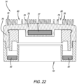
- FIG. 22 is a cross-section of the cleansing attachment.
- references in this specification to “one embodiment,” “an embodiment,” “a preferred embodiment” or any other phrase mentioning the word “embodiment” means that a particular feature, structure, or characteristic described in connection with the embodiment is included in at least one embodiment of the-disclosure and also means that any particular feature, structure, or characteristic described in connection with one embodiment can be included in any embodiment or can be omitted or excluded from any embodiment.
- the appearances of the phrase “in one embodiment” in various places in the specification are not necessarily all referring to the same embodiment, nor are separate or alternative embodiments mutually exclusive of other embodiments.
- various features are described which may be exhibited by some embodiments and not by others and may be omitted from any embodiment.
- any particular feature, structure, or characteristic described herein may be optional.
- FIG. 1 shows a vibration therapy system 10 that includes a vibration therapy device 12 , one or more reciprocating attachments 19 and one or more therapy modules 11 .
- the reciprocating attachments can have different shapes.
- the therapy modules 11 can have different shapes and include different types of therapy, such as light, micro-current, heat, cold, vibration, etc.
- the vibration therapy device includes a housing 13 (two housing halves 13 a and 13 b are shown in FIG. 3 ), a handle portion 14 , a head portion 15 and a switch 16 for activating the motor 17 .
- FIGS. 1 - 8 show the vibration therapy device 12 with a therapy module 11 that is referred to herein as a ring module 18 (due to its shape with a central opening 18 a ) and a reciprocating attachment 19 . As shown in FIG.
- the vibration therapy device 12 includes an electrical source, such as a battery 20 , positioned in the handle portion 14 , the motor 17 positioned in the head portion 15 , and a push rod assembly 21 operatively connected to the motor 17 and configured to reciprocate in response to activation of the motor 17 .
- an electrical source such as a battery 20
- the motor 17 positioned in the head portion 15
- a push rod assembly 21 operatively connected to the motor 17 and configured to reciprocate in response to activation of the motor 17 .
- the rotation of the motor shaft 22 is converted to reciprocating motion of the push rod assembly 21 .
- the push rod assembly includes any set of components for converting the rotation motion of the motor to reciprocating motion of the massage or reciprocating attachment.
- the push rod assembly 21 includes a push rod 23 that is pivotably connected to a reciprocating shaft 24 (see pivot pin 25 ), and an attachment member 26 that is operatively connected to the reciprocating shaft 24 .
- the shaft 26 a of the attachment member extends into and is connected within (via threads, friction fit, interference fit, etc.) an opening 24 a defined in the reciprocating shaft 24 .
- the distal end of the attachment member 26 (which is also the distal end of the push rod assembly 21 ) removably receives the reciprocating attachment 19 .
- the term push rod assembly used herein includes any of the drive train components discussed herein or combinations thereof, e.g., push rod 23 , reciprocating shaft 24 and attachment member 26 or the like that provide reciprocating motion and include the reciprocating attachment on the distal end thereof.
- the push rod assembly also includes the attachment member 26 (and any related components, such as the magnet described below) or any other connector at the end of the reciprocating components that allows connection of a reciprocating attachment to be used for massage or therapy.
- the drive train also includes a counterweight member 28 between the motor shaft 22 and the push rod 23 .
- the motor shaft 22 is received in an opening in the counterweight member 28 and an offset shaft 29 extends from the counterweight member 28 and is received in an opening in the push rod 23 .
- the reciprocating shaft 24 extends through the bush 31 and bush holding structure 33 .
- the motor 17 is secured to a motor mount 30 that includes a plurality of feet 32 that are secured to the housing 13 via threaded fasteners or the like that extend through openings in the feet 32 .
- Dampening rings 34 and dampening washers can also be included. All dampening components herein are made of rubber, silicone or the like and are provided to prevent plastic to plastic or plastic to metal contact and to reduce noise and vibration.
- the attachment member 26 includes the shaft 26 a and a magnet seat 26 b .
- the magnet seat 26 b includes a magnet 27 received therein or otherwise operatively associated therewith.
- the housing 13 includes a cap portion 35 that includes the module seat 50 and a protrusive portion 36 .
- the attachment member 26 extends through an opening in the cap portion such that the magnet seat 26 b is located outside of the housing 13 , and particularly, the protrusive portion 36 of the housing 13 .
- the distal end of the attachment member 26 (the magnet seat 26 b ) removably receives the reciprocating attachment 19 .
- FIG. 3 shows an exemplary reciprocating attachment 19 including the main body portion 19 a , inner support portion 19 b and magnet 27 .
- the head portion 15 includes a module seat 50 that removably receives the therapy modules 11 .
- the vibration therapy system 10 includes an attachment system 44 for properly aligning or mounting and attaching or securing the various therapy modules 11 on the module seat 50 , as well as providing electrical connection or communication (if needed) between the therapy modules 11 and the vibration therapy device 12 .
- the attachment system 44 includes magnetic attraction between the module seat 50 and therapy module 11 and includes one or more complementary securement protrusions 48 and securement recesses 54 extending or protruding from the module seat 50 and/or the back of the therapy module 11 . The securement protrusions are received in the securement recesses.
- FIG. 6 also shows the central opening diameter D 1 of the central opening 18 a of the ring module 18 and the reciprocating attachment diameter D 2 of the reciprocating attachment 19 . As shown, the central opening diameter D 1 is larger than the reciprocating attachment diameter D 2 , such that the reciprocating attachment 19 is configured to reciprocate within and relative to the ring module 18 .
- one securement protrusion 48 extends from the back of the therapy module 11 and one securement recess 54 is defined in the module seat 50 .
- one securement recess 54 is defined in the back of the therapy module 11 and one securement protrusion extends from the module seat 50 .
- at least one of the securement protrusions and at least one of the securement recess include one or more magnet members 52 associated therewith that are magnetically attracted to one another, that help secure the ring module 18 (or other therapy module 11 ) onto the module seat 50 and the vibration therapy device 12 .
- One, two or more magnet members can be included.
- the magnet members 52 are located within the housing of the therapy module (see, e.g., FIGS. 5 and 2 ) and within the housing of the head portion and adjacent to or below the module seat 50 (see, e.g., FIGS. 5 and 19 ).
- Sets of complementary magnets 52 may be positioned around the base of the therapy module 11 and the module seat 50 .
- the module seat 50 includes a first set of six magnets 52 associated therewith and each therapy module 11 includes a second set of magnets 52 associated therewith that are magnetically attracted to the first set of magnets in or associated with the module seat 50 .
- a set can be any number of magnets between 1-25.
- the system includes an electrical connection system 58 between the vibration therapy device 12 and the therapy module 11 .
- the therapy module 11 includes male electrical contacts 60 extending therefrom (see FIGS. 6 and 10 ) and the module seat 50 includes complementary female electrical contacts 62 . Power is supplied from the battery 20 , through the male and female electrical contacts and to the LEDs or other powered components. It will be appreciated that the male and female electrical contacts can be reversed.
- the male or female electrical contacts are associated with one of the securement recesses 54 and one of the securement protrusions 48 .
- the securement protrusion 48 that extends from the back of the therapy module 11 is a magnetic securement protrusion and the securement recess 54 that is defined in the module seat 50 is a magnetic securement recess.
- the securement recess 54 that is defined in the back of the therapy module 11 is an electrical securement recess (and includes male electrical contacts) and the securement protrusion 48 that extends from the module seat 50 is an electrical securement protrusion (and includes female electrical contacts).
- the handle portion 14 forms an angle of about 120 degrees with the reciprocating shaft 24 to avoid blocking the user's view during treatment. Anywhere between 90 degrees and 180 degrees is within the scope of the invention.
- the head portion can be rotatable and/or pivotable and/or swivelable with respect to the handle portion 14 .
- FIG. 8 shows the components of the light ring module 18 including the printed circuit board 37 including the LEDs 38 and proximity sensors 39 .
- the proximity sensors 39 are positioned approximately 180° from another. With respect to 180°, approximately means within 10°. However, they can be positioned anywhere around the ring.
- the proximity sensors 39 are provided so that LED lights in the light module only turn on (or go from dimmed to “treatment level” or off to “treatment level”) when they are less than a predetermined distance from or the lens is in contact with the user's face or skin.
- one proximity sensor 39 is located at about twelve o'clock on the PCB and the other is located at about six o'clock.
- the lights In use, after activating the light ring module, the lights remain off or in a dimmed state until the front surface of the module is placed within a predetermined distance of the user's face, at which point the lights brighten to a treatment level (where the lights will be effective for the desired treatment—e.g., red LED treatment, blue LED treatment or infrared).
- the proximity sensors are programmed such that they only determine the proximity at intervals or at a predetermined frequency (e.g., every one second) so that the lights are not turning on and off every time the device is pulled away from the face or angled during use on the face such that the proximity sensor is out of range. Any type of proximity sensor can be used.
- the proximity sensor emits a beam that is reflected by the user's face.
- the sensor determines the distance with the face based on the time (or frequency) for the beam returning from the user's skin after reflection. It will be appreciated that by having two proximity sensors 180° apart, as long as one is within the predetermined range of distance from the skin (operating surface), the lights will not dim or turn off (or go to a point that is less than the desired treatment level or intensity of the lights).
- the light ring module includes a housing portion 40 , PCB 37 , cover or lens 41 and a light direction member 42 that includes a plurality of openings 43 defined therein.
- the openings 43 are each aligned with an LED 38 and provide a tunnel so that the light beams emitted from each of the LEDs are directed generally parallel to one another and, therefore, generally perpendicular to the cover 41 and the user's skin as the device is used. This helps prevent the light from shining outwardly and into the user's eyes during use.
- the ring module includes the central opening 18 a and an outer surface 41 a .
- the contact surface 19 c of the reciprocating attachment 19 extends further from the module seat 50 than the outer surface 41 a of the ring module 18 .
- Other types of ring modules with other therapies are in the scope of the present invention.
- FIGS. 9 - 11 show another type of therapy module 11 referred to generally herein as a cap module and more specifically (for this particular module) as a micro-current cap module 118 that covers the magnet seat 26 b of the attachment member 26 .
- the micro-current cap module 118 includes a main body portion 70 and a rear recess 72 defined therein that receives the attachment member 26 when the micro-current cap module 118 is fitted on the module seat 50 .
- the rear recess 72 may also be referred to herein as the central opening because regardless of the type of therapy module (cap or ring) that is received on the module seat, the attachment member 26 extends into the central opening (or rear recess).
- the micro-current cap module 118 shown in FIGS. 9 - 11 includes micro-current therapy.
- micro-current therapy can also be included in a ring module.
- the micro-current cap module 118 includes first and second terminals or an anode and cathode 120 . This module includes an electrical connection and magnetic attraction just like the ring module 18 described above. As will be appreciated by those of ordinary skill in the art, when the anode and cathode 120 are placed against a user's skin, an electrical connection is created and micro-current is transmitted into the user's skin to provide micro-current treatment.
- FIGS. 12 , 21 and 22 shows another type of cap module referred to herein as a cleansing cap module or cleansing attachment 74 that includes a plurality of bristles 76 thereon.
- the cleansing attachment 74 includes a main body portion 70 and recess that receives the attachment member 26 when the cleansing attachment 74 is fitted on the module seat 50 .
- the cleansing attachment 74 may also include (but preferably does not include) an electrical connection just like the ring module 18 described above.
- the cleansing attachment 74 preferably also includes a magnet 27 therein that is magnetically attracted to and connects to the magnet 27 in the attachment member 26 .
- the main body portion 70 preferably includes the complementary securement protrusion 48 and recess 54 , like the other therapy modules 11 , that mate with the securement protrusion 48 and recess 54 on the module seat 50 . Therefore, the cleansing cap module is configured to be removably secured to both the attachment member 26 (e.g., via magnets) and to the module seat 50 (e.g., via the complementary securement protrusions and recesses and set of magnets 52 ).
- the cleansing attachment 74 includes a central section 76 that is flexible (for example, it may be made of silicone, rubber or other flexible material). Therefore, during use, when the attachment member 26 reciprocates, the central section 78 flexes. In other words, because the magnets 52 are holding the base of the main body portion 70 on and against the module seat 50 , the central section 78 flexes and moves with each stroke of the attachment member 26 . Therefore, the base of the main body portion 70 remains magnetically secured to the module seat 50 while the attachment member 26 reciprocates against the central section 78 , therefore moving or percussing the central section 78 and the bristles 76 thereof against the user's skin.
- a central section 76 that is flexible (for example, it may be made of silicone, rubber or other flexible material). Therefore, during use, when the attachment member 26 reciprocates, the central section 78 flexes. In other words, because the magnets 52 are holding the base of the main body portion 70 on and against the module seat 50 , the central section 78 flexes
- the central section 78 is a flexible membrane that moves with the reciprocating attachment member 26 .
- the cleansing attachment 74 includes a groove 80 between the inner bristles 76 associated with the central section 78 and the outer bristles 76 that are located radially outwardly from the central section 78 .
- the inner bristles move with the central section 146 and the outer generally bristles remain stationary during reciprocation.
- a cleansing formulation can be placed on the bristles 76 during use.
- the magnets 52 around the base can be omitted and the entire cleansing attachment 74 can reciprocate.
- the complementary securement protrusions and recesses can also be omitted since connection is made between the central magnet 27 and the magnet in the attachment member 26 .
- FIGS. 13 - 16 show a preferred embodiment system for attaching a component with microfiber material thereon (referred to herein as a skin treatment member 88 ) to the reciprocating attachment 19 .
- the skin treatment member 88 includes lotion or some type of skin treatment ointment or fluid thereon and, therefore, is packaged in a pod member 90 that includes a container portion 92 and a lid 94 .
- the skin treatment member 88 includes a generally ring shaped main body portion 96 and a delivery portion 98 that is preferably made of microfiber and includes the lotion thereon.
- the skin treatment member 88 is attachable or securable to the reciprocating attachment 19 .
- the main body portion 96 includes one or more ridge members 100 on the inside surface thereof and extending inwardly that are received in one or more grooves 102 defined in the outer surface of the reciprocating attachment 19 .
- the skin treatment member 88 preferably also includes a handle or tab 106 extending from the main body portion 96 that aids with attachment and removal of the skin treatment member 88 from the reciprocating attachment 19 . In use, the skin treatment member 88 is removed from the pod member 90 (by peeling back the lid 94 ) and the treatment member is placed or seated on the reciprocating attachment 19 .
- the main body portion 96 is made of a flexible material (such as plastic) so the ridge members 100 flex over the reciprocating attachment 19 and snap into the groove 102 on the outer surface of the reciprocating attachment.
- the delivery portion stretches across or spans the top or outer contact surface of the reciprocating attachment 19 .
- the delivery portion 98 is then placed against the user's face and the device is activated such that the reciprocating attachment 19 (also referred to herein as a mallet) with the treatment member 88 thereon vibrates or percusses against the user's skin.
- the use can pull on the tab 106 to separate the treatment member 88 from the mallet 19 . As shown in FIG.
- the skin treatment member 88 can be placed on the mallet 19 when the ring module 18 is on the device. Therefore, the LED light therapy can be used simultaneously with the vibration therapy and the treatment member therapy.
- the groove 102 is preferably located further from the module seat 50 than the outer surface 41 a or outside of the ring module so that the skin treatment member 88 secured in the groove can reciprocate outside of the ring module.
- FIGS. 17 A- 17 C show a control center 108 (or user interface—UI) that includes a display screen 110 and one or more buttons and/or switches that can be used for controlling the device 12 and the various therapy modules 11 .
- the buttons can control different modes, different intensities, etc.
- the control center includes display screen 110 , motor toggle button 126 (for toggling through different frequencies or speeds for the attachment member 26 and any reciprocating attachment thereon), module toggle button 128 (for toggling through different intensities or options for the therapy modules electrically connected to the device) and a power switch 16 .
- FIG. 17 A shows the display screen 110 with the motor speed level 112 at the top and the therapy module level 114 (with the light ring module symbol thereon) at the bottom.
- FIG. 17 B shows the display screen 110 with the battery level 116 at the top and the therapy module level 114 (with the heat ring module symbol thereon) at the bottom.
- FIG. 17 C shows the display screen 110 with nothing on the top and the therapy module level 114 (with the micro-current symbol thereon) at the bottom.
- Other symbols and the like that can be shown in the display screen include Bluetooth.
- the control center 108 is in data communication with the controller and associated components for controlling the device 12 .
- the device can recognize, sense or determine what type of therapy module has been seated on and electrically connected to the device.
- the information or data regarding the type of module is preferably communicated through the two prongs allocated for data communication.
- the module toggle button 128 allows the module toggle button 128 to toggle through the modes of the proper module and for the proper therapy module level to be displayed on display 110 .
- the motor is not activated (to reciprocate the attachment member) because the attachment member and magnet seat is located inside the cap module. This prevents the attachment member 26 from reciprocating within the cap module.
- the motor can be activated so that the reciprocating attachment can reciprocate within the central opening of the ring module.
- the vibration therapy system can be provided to users as a kit (e.g., within a case, box, bag or the like).
- the kit can include the vibration therapy device, one or more reciprocating attachments and one or more therapy modules.
- an exemplary kit includes the device, the light ring module, the micro-current cap module, the reciprocating attachment with the groove therearound and charger all within a case or container.
- FIGS. 18 - 20 show another preferred embodiment of the vibration therapy device 12 . All disclosure related to other embodiments herein is also relevant to the embodiment shown in FIGS. 18 - 20 .
- the reciprocating attachment 19 includes an attachment member recess 130 defined therein.
- the attachment member 26 is received in the attachment member recess 130 .
- the attachment member 26 defines an attachment member diameter D 3 and the attachment member recess 130 defines an attachment member recess diameter D 4 .
- the attachment member diameter D 3 is smaller than the attachment member recess diameter D 4 , which allows the reciprocating attachment 19 to be received on the attachment member 26 .
- the first and second magnets 27 in the attachment member and the reciprocating attachment 19 secure the reciprocating attachment 19 on the attachment member 26 .
- the first and second magnets 27 are strong enough to hold the reciprocating attachment 19 on the attachment member 26 during reciprocation, and, in particular, with the reciprocation occurring in the any of the frequency and amplitude ranges discussed herein. In particular, the magnets prevent the reciprocating attachment 19 from disconnecting from the attachment member 26 during reciprocation.
- the amplitude range is between 1.0 mm and 5.0 mm and in a more preferred embodiment, the amplitude range is between 2 mm and 4 mm. In a most preferred embodiment, the amplitude range is between 2.9 mm and 3.1 mm.
- the frequency is between 25 Hz and 45 Hz when operating at any of the amplitudes (or strokes) discussed herein.
- the linear velocity is between 0.06 m/s and 0.5 m/s. In a more preferred embodiment, the linear velocity is between 0.11 m/s and 0.4 m/s.
- the vibration therapy device 12 includes a flexible sleeve 132 that includes a sleeve portion 134 , an annular flange 136 , a central opening 138 , an annular ridge 140 and proximal and distal ends 132 a and 132 b respectively.
- the flexible sleeve 132 surrounds the distal end of the reciprocating shaft 24 .
- the distal end of the flexible sleeve 132 b is secured to the attachment member 26 and the proximal end of the flexible sleeve 132 a is secured to and/or within the housing 13 or a component thereof.
- the flexible sleeve 132 provides water resistance and helps prevent moisture from getting into the housing interior.
- the reciprocating shaft 24 includes an opening 24 a that receives the shaft 26 a of the attachment member 26 .
- the interior of opening 24 a and the exterior of shaft 26 a include complementary threading to secure the shaft 26 a within the opening 24 a .
- the distal end of the flexible sleeve 132 b is secured between the distal end of the reciprocating shaft and the attachment member 26 , and, more particularly, the distal end of the flexible sleeve 132 b extends into opening 24 a and is secured between the inner surface of the opening 24 a and the outer surface of shaft 26 a .
- the housing includes a protrusive portion 36 that is part of cap 35 .
- Each of the housing halves 13 a and 13 b include part of a nose portion 142 that includes an annular groove 144 defined therein.
- the annular groove 144 receives the annular ridge 140 that extends downwardly from the annular flange 136 of the flexible sleeve 132 , as is best shown in FIG. 19 .
- the housing includes a protrusive portion, wherein the proximal end of the flexible sleeve is secured by the protrusive portion.
- the proximal end of the flexible sleeve 132 a (which is part of the annular flange 136 ) is sandwiched between the protrusive portion 36 and the nose portion 142 .
- the words “comprise,” “comprising,” and the like are to be construed in an inclusive sense, as opposed to an exclusive or exhaustive sense; that is to say, in the sense of “including, but not limited to.”
- the terms “connected,” “coupled,” or any variant thereof means any connection or coupling, either direct or indirect, between two or more elements; the coupling of connection between the elements can be physical, logical, or a combination thereof.
- the words “herein,” “above,” “below,” and words of similar import when used in this application, shall refer to this application as a whole and not to any particular portions of this application.
- any method(s) disclosed or described herein either explicitly or implicitly are shown and described in a particular order, the order of the operations of each method may be altered so that certain operations may be performed in an inverse order or so that certain operations may be performed, at least in part, concurrently with other operations.
- instructions or sub-operations of distinct operations may be implemented in an intermittent and/or alternating manner.
Landscapes
- Health & Medical Sciences (AREA)
- Life Sciences & Earth Sciences (AREA)
- Animal Behavior & Ethology (AREA)
- General Health & Medical Sciences (AREA)
- Public Health (AREA)
- Veterinary Medicine (AREA)
- Epidemiology (AREA)
- Pain & Pain Management (AREA)
- Physical Education & Sports Medicine (AREA)
- Rehabilitation Therapy (AREA)
- Percussion Or Vibration Massage (AREA)
- Engineering & Computer Science (AREA)
- Biomedical Technology (AREA)
- Nuclear Medicine, Radiotherapy & Molecular Imaging (AREA)
- Radiology & Medical Imaging (AREA)
- Heart & Thoracic Surgery (AREA)
- Vascular Medicine (AREA)
- Biophysics (AREA)
- Pathology (AREA)
- Oral & Maxillofacial Surgery (AREA)
- Plastic & Reconstructive Surgery (AREA)
Abstract
Description
Claims (19)
Priority Applications (12)
| Application Number | Priority Date | Filing Date | Title |
|---|---|---|---|
| US17/705,300 US11730668B2 (en) | 2020-06-29 | 2022-03-26 | Vibrating therapy system and device |
| US17/718,007 US12016818B2 (en) | 2020-06-29 | 2022-04-11 | Vibrating therapy system and device |
| PCT/US2022/028309 WO2022236162A1 (en) | 2021-05-07 | 2022-05-09 | Percussive therapy device with interchangeable modules |
| US17/739,630 US11890253B2 (en) | 2018-12-26 | 2022-05-09 | Percussive therapy device with interchangeable modules |
| US18/162,499 US12064387B2 (en) | 2018-12-26 | 2023-01-31 | Percussive therapy device with electrically connected attachment |
| PCT/US2023/016057 WO2023192098A1 (en) | 2022-03-26 | 2023-03-23 | Vibration therapy system and device |
| CN202380030840.XA CN118946337A (en) | 2022-03-26 | 2023-03-23 | Vibration therapy systems and devices |
| EP23781596.4A EP4499018A1 (en) | 2022-03-26 | 2023-03-23 | Vibration therapy system and device |
| US18/346,681 US20230381060A1 (en) | 2020-06-29 | 2023-07-03 | Vibrating therapy system and device |
| US18/433,207 US12329711B2 (en) | 2018-12-26 | 2024-02-05 | Percussive therapy device with interchangeable modules |
| US18/739,019 US20240325241A1 (en) | 2020-06-29 | 2024-06-10 | Therapy system and device |
| US18/809,073 US12396919B2 (en) | 2024-08-19 | Percussive therapy device with electrically connected attachment |
Applications Claiming Priority (5)
| Application Number | Priority Date | Filing Date | Title |
|---|---|---|---|
| US202063045365P | 2020-06-29 | 2020-06-29 | |
| US202063065348P | 2020-08-13 | 2020-08-13 | |
| US202163133530P | 2021-01-04 | 2021-01-04 | |
| US17/361,966 US11331244B2 (en) | 2020-06-29 | 2021-06-29 | Vibration therapy system and device |
| US17/705,300 US11730668B2 (en) | 2020-06-29 | 2022-03-26 | Vibrating therapy system and device |
Related Parent Applications (2)
| Application Number | Title | Priority Date | Filing Date |
|---|---|---|---|
| US17/244,278 Continuation US11564860B2 (en) | 2018-12-26 | 2021-04-29 | Percussive therapy device with electrically connected attachment |
| US17/361,966 Continuation-In-Part US11331244B2 (en) | 2018-12-26 | 2021-06-29 | Vibration therapy system and device |
Related Child Applications (4)
| Application Number | Title | Priority Date | Filing Date |
|---|---|---|---|
| US16/675,772 Continuation-In-Part US10702448B2 (en) | 2015-06-20 | 2019-11-06 | Percussive massage device and method of use |
| US17/718,007 Continuation US12016818B2 (en) | 2020-06-29 | 2022-04-11 | Vibrating therapy system and device |
| US17/739,630 Continuation-In-Part US11890253B2 (en) | 2018-12-26 | 2022-05-09 | Percussive therapy device with interchangeable modules |
| US18/346,681 Continuation US20230381060A1 (en) | 2020-06-29 | 2023-07-03 | Vibrating therapy system and device |
Publications (2)
| Publication Number | Publication Date |
|---|---|
| US20220211575A1 US20220211575A1 (en) | 2022-07-07 |
| US11730668B2 true US11730668B2 (en) | 2023-08-22 |
Family
ID=82219274
Family Applications (4)
| Application Number | Title | Priority Date | Filing Date |
|---|---|---|---|
| US17/705,300 Active US11730668B2 (en) | 2018-12-26 | 2022-03-26 | Vibrating therapy system and device |
| US17/718,007 Active US12016818B2 (en) | 2020-06-29 | 2022-04-11 | Vibrating therapy system and device |
| US18/346,681 Pending US20230381060A1 (en) | 2020-06-29 | 2023-07-03 | Vibrating therapy system and device |
| US18/739,019 Pending US20240325241A1 (en) | 2020-06-29 | 2024-06-10 | Therapy system and device |
Family Applications After (3)
| Application Number | Title | Priority Date | Filing Date |
|---|---|---|---|
| US17/718,007 Active US12016818B2 (en) | 2020-06-29 | 2022-04-11 | Vibrating therapy system and device |
| US18/346,681 Pending US20230381060A1 (en) | 2020-06-29 | 2023-07-03 | Vibrating therapy system and device |
| US18/739,019 Pending US20240325241A1 (en) | 2020-06-29 | 2024-06-10 | Therapy system and device |
Country Status (1)
| Country | Link |
|---|---|
| US (4) | US11730668B2 (en) |
Cited By (1)
| Publication number | Priority date | Publication date | Assignee | Title |
|---|---|---|---|---|
| US12329711B2 (en) * | 2018-12-26 | 2025-06-17 | Therabody, Inc. | Percussive therapy device with interchangeable modules |
Families Citing this family (26)
| Publication number | Priority date | Publication date | Assignee | Title |
|---|---|---|---|---|
| US11730668B2 (en) | 2020-06-29 | 2023-08-22 | Therabody, Inc. | Vibrating therapy system and device |
| KR102793512B1 (en) * | 2019-10-31 | 2025-04-11 | 삼성전자주식회사 | Photomask device and control method thereof |
| US11752064B2 (en) | 2020-12-02 | 2023-09-12 | PlayMakar, Inc. | Constrained and repositionable percussive massage device tool and tool receiver |
| USD1081978S1 (en) * | 2021-02-25 | 2025-07-01 | Haleon Ch Sarl | Applicator head with dosing aid |
| USD1004793S1 (en) | 2021-03-02 | 2023-11-14 | Therabody, Inc. | Facial treatment device |
| USD1018885S1 (en) | 2021-10-22 | 2024-03-19 | PlayMakar, Inc. | Dual head percussive massager tool with dome tips |
| USD1018887S1 (en) | 2021-10-22 | 2024-03-19 | PlayMakar, Inc. | Dual head percussive massager tool base |
| USD1018886S1 (en) | 2021-10-22 | 2024-03-19 | PlayMakar, Inc. | Dual head percussive massager tool with round tips |
| USD987845S1 (en) | 2021-10-28 | 2023-05-30 | Play Makar Inc. | Massage gun attachment head |
| USD987846S1 (en) | 2021-10-28 | 2023-05-30 | PlayMakar Inc. | Massager gun attachment shaft |
| USD1000626S1 (en) | 2021-11-02 | 2023-10-03 | PlayMakar, Inc. | Percussive massage gun |
| USD980805S1 (en) | 2021-11-02 | 2023-03-14 | PlayMakar, Inc. | Massager control display |
| USD998815S1 (en) | 2021-12-01 | 2023-09-12 | PlayMakar, Inc. | Massage gun head seal |
| CN114305661B (en) * | 2021-12-31 | 2025-07-01 | 武汉市海沁医疗科技有限公司 | A dot matrix handle of a thermal therapy device |
| USD988531S1 (en) | 2022-01-12 | 2023-06-06 | PlayMakar Inc. | Massage gun acupressure tip |
| USD1006242S1 (en) * | 2022-01-20 | 2023-11-28 | PlayMakar, Inc. | Percussive massager device connecting rod |
| US11672728B1 (en) | 2022-04-05 | 2023-06-13 | PlayMakar Inc. | Selectable, configurable and interchangeable massage tool head system for percussion massage devices |
| USD977662S1 (en) * | 2022-04-11 | 2023-02-07 | Therabody, Inc. | Massage device |
| USD975869S1 (en) | 2022-04-11 | 2023-01-17 | Therabody, Inc. | Massage device |
| US11850204B2 (en) | 2022-05-09 | 2023-12-26 | PlayMakar, Inc. | System and method for locking percussion settings on a massage device |
| US20220370287A1 (en) * | 2022-06-09 | 2022-11-24 | Shenzhen Alltokee Technology Co., Ltd | Massage device with replaceable structure |
| USD1041672S1 (en) | 2022-12-05 | 2024-09-10 | 2815866 Ontario Inc. | Myofascial release device |
| USD1057188S1 (en) | 2022-12-05 | 2025-01-07 | 2815866 Ontario Inc. | Head component for myofascial release device |
| KR20250025589A (en) * | 2023-08-11 | 2025-02-24 | 썬전 에스-한더 테크놀로지 컴퍼니 리미티드 | Transformable massager |
| US20240299770A1 (en) * | 2023-10-12 | 2024-09-12 | Ling-Ho LAM | Cranial detoxifier device |
| EP4548803A1 (en) * | 2023-11-02 | 2025-05-07 | Koninklijke Philips N.V. | Personal care appliance |
Citations (158)
| Publication number | Priority date | Publication date | Assignee | Title |
|---|---|---|---|---|
| US1955863A (en) | 1931-02-19 | 1934-04-24 | Schmidt Gustave Franz | Electro-therapeutic and mechanical vibratory device |
| US2183726A (en) | 1939-02-17 | 1939-12-19 | Sommer Victor | Apparatus for the treatment of the skin or the like |
| US4088128A (en) * | 1975-09-04 | 1978-05-09 | Mabuchi Motor Co., Ltd. | Beauty treatment device |
| US4513737A (en) * | 1979-12-29 | 1985-04-30 | Kenichi Mabuchi | Beauty treatment device |
| US4858600A (en) | 1987-07-22 | 1989-08-22 | General Ideas & Products Ltd. | Massaging appliance |
| US5103809A (en) | 1990-12-05 | 1992-04-14 | Deluca Pierre | Massaging device |
| US5471695A (en) * | 1994-08-31 | 1995-12-05 | Aiyar; Sanjay | Motorized brush |
| US6401289B1 (en) * | 2001-08-24 | 2002-06-11 | Linda S. Herbert | Skin cleaning device |
| US20020082536A1 (en) * | 2000-12-27 | 2002-06-27 | Tucek Kevin B. | Chiropractic percussor apparatus having compact percussion-applying head assembly centrally attached to reciprocatory push rod |
| US6524329B1 (en) | 2001-03-08 | 2003-02-25 | Tru-Light Corporation | Body processing using light |
| US6535761B2 (en) | 2001-04-06 | 2003-03-18 | Mattioli Engineering Ltd. | Method and apparatus for skin absorption enhancement |
| US20040030325A1 (en) | 2001-12-05 | 2004-02-12 | Nicholas Cahir | Removable attachments for laser emitting devices |
| US6743215B2 (en) | 2001-04-06 | 2004-06-01 | Mattioli Engineering Ltd. | Method and apparatus for skin absorption enhancement and cellulite reduction |
| US6748266B2 (en) | 2001-04-06 | 2004-06-08 | Mattioli Engineering Ltd. | Method and apparatus for skin absorption enhancement and transdermal drug delivery |
| US6766199B2 (en) | 2002-10-10 | 2004-07-20 | Proventure (Far East), Limited | Skin/hair treatment method and system |
| US20040147984A1 (en) | 2001-11-29 | 2004-07-29 | Palomar Medical Technologies, Inc. | Methods and apparatus for delivering low power optical treatments |
| US20040260212A1 (en) * | 2003-06-17 | 2004-12-23 | Doctors Tech Co., Ltd. | Skin care appliance |
| US20050043653A1 (en) | 2003-08-21 | 2005-02-24 | Azalea Way Consumer Products Llc, | Skin cleansing and moisturizing device |
| US6974224B2 (en) | 2003-07-30 | 2005-12-13 | Tru-Light Corporation | Modularized light processing of body components |
| US6980854B2 (en) | 2001-04-06 | 2005-12-27 | Mattioli Engineering Ltd. | Method and apparatus for skin absorption enhancement and transdermal drug delivery of lidocaine and/or other drugs |
| US7010343B2 (en) | 2001-04-06 | 2006-03-07 | Mattioli Engineering Ltd. | Method and apparatus for skin absorption enhancement and transdermal drug delivery |
| US7014639B2 (en) | 2003-02-25 | 2006-03-21 | Skincare Technology, Inc. | Apparatus for aesthetic skin treatments |
| US7083580B2 (en) | 2001-04-06 | 2006-08-01 | Mattioli Engineering Ltd. | Method and apparatus for skin absorption enhancement and transdermal drug delivery |
| US20070038206A1 (en) | 2004-12-09 | 2007-02-15 | Palomar Medical Technologies, Inc. | Photocosmetic device |
| US7204832B2 (en) | 1996-12-02 | 2007-04-17 | Pálomar Medical Technologies, Inc. | Cooling system for a photo cosmetic device |
| US20070179573A1 (en) | 2006-02-02 | 2007-08-02 | Richard Laurent | Method and apparatus for stimulating hair growth |
| US7258675B2 (en) | 2003-05-21 | 2007-08-21 | Thomas Nichols | Facial rejuvenation device and method |
| US7282036B2 (en) | 2003-10-24 | 2007-10-16 | Masatoshi Masuda | Cosmetic device having vibrator |
| US20080014011A1 (en) | 2006-06-30 | 2008-01-17 | Rossen Joel S | Therapeutic Cosmetic Dispensing Device |
| US20080065176A1 (en) | 2006-09-11 | 2008-03-13 | Rainbow Communications, Inc. | Vacuum and negative ions assisted phototheraphy device |
| US20080103560A1 (en) | 2006-10-26 | 2008-05-01 | Lumiport, Llc | Ultraviolet indicator light therapy device |
| US20080103563A1 (en) | 2006-10-26 | 2008-05-01 | Lumiport, Llc | Light therapy personal care device |
| US20080119913A1 (en) | 2006-10-26 | 2008-05-22 | Lumiport, Llc | Light therapy personal care device |
| US20080125835A1 (en) | 2006-02-02 | 2008-05-29 | Richard Laurent | Method and apparatus for light therapy |
| US20080193493A1 (en) | 1999-10-04 | 2008-08-14 | Dean Rhoades | Method for treating skin with a pad |
| US20080215123A1 (en) | 2006-02-09 | 2008-09-04 | Maricle Charles E | Laser Therapy Device For Animals |
| US20080234611A1 (en) * | 2007-03-19 | 2008-09-25 | Twinbird Corporation | Massaging Device |
| US20080275532A1 (en) | 2003-09-12 | 2008-11-06 | Ya-Man Ltd. | Treatment Device |
| US20090043293A1 (en) | 2007-08-10 | 2009-02-12 | Eleme Medical Inc. | Multi-module skin or body treatment device and the method of using |
| US20090182249A1 (en) * | 2008-01-16 | 2009-07-16 | Twinbird Corporation | Massaging device |
| US20090234338A1 (en) | 2008-03-11 | 2009-09-17 | Shaser, Inc. | Reducing sensations experienced during light-based dermatologic treatment procedures |
| US20090287195A1 (en) | 2001-11-29 | 2009-11-19 | Palomar Medical Technologies, Inc. | Methods and apparatus for delivering low power optical treatments |
| US20100121419A1 (en) | 2008-11-13 | 2010-05-13 | Ryan Douglas | Control of light sources for light therapies |
| US20100137752A1 (en) | 2007-05-31 | 2010-06-03 | Gerold Heine | Medical Apparatus For Treatment Of The Human Or Animal Body By Mechanical Pressure Waves Or Shock Waves |
| US20100274329A1 (en) | 2009-04-24 | 2010-10-28 | Chris Bradley | System and method for skin care using light and microcurrents |
| US20100274162A1 (en) | 2009-04-22 | 2010-10-28 | Dale Marlyn Marie Evans | Thermal Massager |
| US20100312157A1 (en) | 2009-06-03 | 2010-12-09 | Yongxing Yan | Rotary massage device |
| US20110040235A1 (en) | 2009-08-11 | 2011-02-17 | Castel J Chris | Multi-Modal Drug Delivery System |
| US20110106067A1 (en) | 2009-10-29 | 2011-05-05 | Synoia Technologies Ltd. | Multi-application skin care system |
| US20110184499A1 (en) | 2010-01-27 | 2011-07-28 | Robert Radi | Skin treatment device and system |
| US20120065555A1 (en) | 2010-09-10 | 2012-03-15 | Eun Suk LEE | Massage apparatus for skin care |
| US8157753B2 (en) | 2008-03-27 | 2012-04-17 | Thomas Nichols | Personal care vaporizing device |
| US20120109041A1 (en) | 2009-03-30 | 2012-05-03 | Jutta Munz | Applicator device for cosmetic and/or medical use |
| US8182473B2 (en) | 1999-01-08 | 2012-05-22 | Palomar Medical Technologies | Cooling system for a photocosmetic device |
| US20120253246A1 (en) * | 2010-12-24 | 2012-10-04 | Ya-Man Ltd. | Tapping device for producing beautiful skin |
| US20120310124A1 (en) | 2011-06-03 | 2012-12-06 | Chuen Chern Co., Ltd. | Liquid dispensing massage device with double switch |
| US20130012851A1 (en) | 2011-06-18 | 2013-01-10 | John Fahmie | Versatile massage therapy pole |
| US20130046212A1 (en) | 2010-07-01 | 2013-02-21 | Thomas Nichols | Handheld facial massage and light therapy device |
| US8382690B2 (en) | 2008-01-15 | 2013-02-26 | Industry Foundation Of Chonnam National University | Portable physis-stimulating device for promoting growth with two-phase ultrasonic vibration generators and led elements |
| US20130060176A1 (en) | 2011-06-30 | 2013-03-07 | Thomas Nichols | Handheld Motorized Facial Brush Having Pivoting, Floating Head |
| US8506506B2 (en) | 2009-01-12 | 2013-08-13 | Solta Medical, Inc. | Tissue treatment apparatus with functional mechanical stimulation and methods for reducing pain during tissue treatments |
| US20130213431A1 (en) * | 2010-11-05 | 2013-08-22 | Synoia Technologies Ltd | Cosmetic applicator with sponge to absorb substance and to prevent leakage thereof |
| USD693932S1 (en) | 2011-02-22 | 2013-11-19 | Thomas Nichols | Handheld facial massage device, detachable application brush and charging base therefor |
| US20140031866A1 (en) * | 2012-07-19 | 2014-01-30 | Activator Methods International, Ltd. | Chiropractic adjustor system and method |
| US20140096786A1 (en) * | 2011-04-08 | 2014-04-10 | L'oreal | Hair treatment method |
| US8696605B2 (en) | 2008-03-27 | 2014-04-15 | Thomas Nichols | Personal care vaporizer device for hands |
| US20140128780A1 (en) | 2011-04-01 | 2014-05-08 | Syneron Beauty Ltd | Treatment Device |
| US20140135798A1 (en) | 2012-11-13 | 2014-05-15 | Jonathan David | Light therapy skin device |
| US20140219701A1 (en) | 2013-02-05 | 2014-08-07 | Hct Packaging, Inc. | Cosmetic device with active temperature modulation |
| US20140276255A1 (en) | 2013-03-15 | 2014-09-18 | Aaron Paul McGushion | Massage Device Having a Heat Reservoir |
| US20140288364A1 (en) | 2013-03-20 | 2014-09-25 | LoveMuah, LLC | Oscillating massage device with interchangeable attachment tips |
| US20140323927A1 (en) | 2013-04-25 | 2014-10-30 | Nancy Y. KIM | Device for Skin Care and Massaging |
| US20140336540A1 (en) | 2013-05-07 | 2014-11-13 | Shawn Chen | Cleaning and massaging system |
| US20140371637A1 (en) * | 2012-03-05 | 2014-12-18 | Bomtech Electronics Co. Ltd. | Skincare apparatus |
| US20140378555A1 (en) | 2012-01-06 | 2014-12-25 | Aesthetic Medical Devices Llc | Facial treatment device |
| US20150005682A1 (en) * | 2013-07-01 | 2015-01-01 | Good Fortune 5, Llc | Massaging device |
| US8945104B2 (en) | 2008-08-22 | 2015-02-03 | Envy Medical, Inc. | Microdermabrasion system with combination skin therapies |
| US20150045702A1 (en) | 2013-08-08 | 2015-02-12 | Mei-Chi-Na Hsinyen Co., Ltd. | Cosmetic device disposed with magnetic attraction structure and replaceable cosmetic assembly |
| US20150100002A1 (en) | 2013-10-07 | 2015-04-09 | So-Young Choi | Skin care device with multiple functions |
| US20150119771A1 (en) | 2013-10-28 | 2015-04-30 | PSOAS Massage Therapy Offices, P.C. | Device and method for trigger point massage therapy |
| US9084587B2 (en) | 2009-12-06 | 2015-07-21 | Syneron Medical Ltd | Method and apparatus for personal skin treatment |
| US20150202114A1 (en) * | 2012-07-10 | 2015-07-23 | Koninklijke Philips N.V. | Device for treating skin |
| USD736399S1 (en) | 2014-01-28 | 2015-08-11 | Thomas Nichols | Handheld facial massage and microcurrent therapy device |
| US20150224020A1 (en) | 2012-07-26 | 2015-08-13 | Syneron Beauty Ltd | Home-use cosmetic treatment device |
| US20150265825A1 (en) | 2014-03-21 | 2015-09-24 | L'oreal | Combined sonic and iontophoretic skin care device |
| US20150283025A1 (en) | 2014-04-08 | 2015-10-08 | Ori Ledany | Portable massage, magnet and light therapy device |
| US20150297393A1 (en) | 2014-03-17 | 2015-10-22 | Aaron Paul McGushion | Massage Device Having a Heat Reservoir |
| US20150305969A1 (en) | 2012-11-22 | 2015-10-29 | Seb S.A. | Massaging Appliance Equipped with Interchangeable and Distinguishable Massaging Heads |
| US9272141B2 (en) | 2010-07-01 | 2016-03-01 | Thomas Nichols | Handheld facial massage and microcurrent therapy device |
| US9278045B2 (en) | 2011-08-26 | 2016-03-08 | Louis Scerbo | Facial rejuvenating apparatus |
| US20160184162A1 (en) | 2014-12-30 | 2016-06-30 | L'oreal | Combined sonic and heat skin care device |
| US20160192814A1 (en) * | 2013-08-07 | 2016-07-07 | Glovics Co., Ltd. | Auto-cleansing apparatus |
| USD764173S1 (en) | 2014-09-10 | 2016-08-23 | Thomas Nichols | Handheld motorized facial brush having pivoting, floating head with charging stand |
| USD765982S1 (en) | 2015-01-28 | 2016-09-13 | Thomas Nichols | Handheld motorized facial brush having three floating heads |
| US20160287034A1 (en) * | 2015-04-03 | 2016-10-06 | Water Pik, Inc. | Skin cleansing and massaging system |
| US20160324719A1 (en) | 2014-01-22 | 2016-11-10 | Ekaabo Inc. | Portable compress device and method of use |
| US20170049278A1 (en) | 2014-05-06 | 2017-02-23 | Koninklijke Philips N.V. | Bodycare device |
| US20170056685A1 (en) | 2015-08-25 | 2017-03-02 | Koninklijke Philips N.V. | Skin care system, device and method |
| US9585687B2 (en) | 2011-08-09 | 2017-03-07 | Syneron Medical Ltd. | Method and apparatus for cosmetic skin care |
| US20170072175A1 (en) | 2015-09-08 | 2017-03-16 | Stanley Batiste | Dermatology Treatment Device |
| US20170128130A1 (en) | 2014-03-21 | 2017-05-11 | Seb S.A. | Treatment Apparatus With a Light Guide |
| US20170189670A1 (en) | 2015-12-30 | 2017-07-06 | L'oreal | Iontophoresis electrodes |
| US20170202732A1 (en) | 2012-09-04 | 2017-07-20 | Thomas Nichols | Handheld Motorized Facial Brush Having Specialized Torque Transfer Clip |
| US20170238686A1 (en) | 2016-02-23 | 2017-08-24 | Braun Gmbh | Cosmetic Device With Exchangeable Application Head |
| US9808646B2 (en) | 2009-10-27 | 2017-11-07 | Klox Technologies Inc. | Device for personal use in phototherapy |
| USD803572S1 (en) | 2015-11-03 | 2017-11-28 | Thomas Nichols | Combination handheld motorized facial brush and charging stand |
| US20180015299A1 (en) | 2015-02-03 | 2018-01-18 | Ino Beauty Inc. | Anti-aging device for stimulating scalp and hair health |
| US20180031090A1 (en) | 2016-07-28 | 2018-02-01 | L'oréal | Applicator attachment having a flexible membrane to convert oscillating rotational motion to orthogonal reciprocating motion |
| US20180031089A1 (en) | 2016-07-28 | 2018-02-01 | L'oreal | Applicator attachment having cams to convert oscillating rotational motion to orthogonal reciprocating motion |
| US20180050440A1 (en) * | 2016-08-18 | 2018-02-22 | Jei Mou Industrial Co., Ltd. | Magnetic Tool Connector |
| US20180133470A1 (en) | 2016-11-12 | 2018-05-17 | Create Co., Ltd. | Composite device of ultrasound and microcurrent for skin care |
| US20180168318A1 (en) | 2015-08-18 | 2018-06-21 | L'oreal | Connected photo-activatable formulation applicator |
| US20180185236A1 (en) | 2017-01-05 | 2018-07-05 | Benzion Levi | Multifunctional facial and body treatment device |
| US20180295980A1 (en) * | 2015-10-13 | 2018-10-18 | Koninklijke Philips N.V. | Heating and cooling supply for facial brush |
| US10124165B2 (en) | 2012-01-16 | 2018-11-13 | Swiss Spa System Ltd. | Hand-held device for electrically assisted dermal treatment |
| US20190015294A1 (en) * | 2017-07-11 | 2019-01-17 | Theragun, LLC | Attachment system for a plurality of treatment members |
| US10278888B2 (en) | 2015-09-21 | 2019-05-07 | Seb S.A. | Treatment device with light guide |
| US10285722B2 (en) | 2014-03-14 | 2019-05-14 | Alain FAVIE | Microdermabrasion device and microdermabrasion method |
| WO2019097291A1 (en) | 2017-11-16 | 2019-05-23 | Filip Sedic | Skincare devices and methods of use |
| WO2019150887A1 (en) | 2018-01-31 | 2019-08-08 | 株式会社Mtg | Cosmetic device |
| US10376659B2 (en) | 2013-05-08 | 2019-08-13 | Thomas Nichols | Personal care vaporizer device for the eye area of the face |
| WO2019155210A2 (en) | 2018-02-08 | 2019-08-15 | Jackson Design Ltd | Massage Therapy Apparatus |
| US10383486B2 (en) | 2015-10-29 | 2019-08-20 | Thomas Nichols | Handheld motorized facial brush having three floating heads |
| US20190254922A1 (en) | 2018-02-22 | 2019-08-22 | Hyper Ice, Inc. | Battery-powered percussive massage device |
| US20190262607A1 (en) | 2010-07-01 | 2019-08-29 | Thomas Nichols | Handheld facial massage and light therapy device |
| US20190290531A1 (en) * | 2016-08-05 | 2019-09-26 | Koninklijke Philips N.V. | Thermal skin treatment device |
| US20190343712A1 (en) | 2018-05-10 | 2019-11-14 | Guangzhou Mozhen Electronic Technology Co., Ltd. | Inductive Therapeutical Instrument Generating Electric Current and Skin Care Method |
| US10511777B2 (en) | 2016-11-08 | 2019-12-17 | Thomas Nichols | Personal care device with camera |
| US20190388707A1 (en) | 2018-06-20 | 2019-12-26 | Omm Imports, Inc. | Therapeutic device providing heat and light and head assembly for same |
| US10518097B2 (en) | 2013-12-30 | 2019-12-31 | L'oreal | Workpiece with integrated battery |
| WO2020028329A1 (en) | 2018-07-31 | 2020-02-06 | L'oreal | Cold plasma generating devices, systems, and methods |
| US20200086137A1 (en) | 2018-09-19 | 2020-03-19 | Lg Electronics Inc. | Pet care device and method for controlling pet care device |
| US20200093945A1 (en) | 2017-06-19 | 2020-03-26 | Lg Electronics Inc. | Skin care device |
| US20200113322A1 (en) | 2017-04-17 | 2020-04-16 | Koninklijke Philips N.V. | A personal care device |
| US20200129372A1 (en) | 2018-10-31 | 2020-04-30 | Lifetrons Switzerland Group Limited | Beauty device |
| KR20200051098A (en) * | 2018-11-02 | 2020-05-13 | 시너지미모스 주식회사 | Device for skin care |
| US20200154874A1 (en) * | 2018-11-19 | 2020-05-21 | Qyk Brands, LLC | Skincare device |
| US10661072B2 (en) | 2017-05-25 | 2020-05-26 | Nse Products, Inc. | TENS attachment for device for cleansing and treating skin |
| US20200179220A1 (en) | 2018-12-10 | 2020-06-11 | JJJ Health LLC | Cupping device and method for facial and skin treatment |
| US20200187635A1 (en) * | 2018-12-18 | 2020-06-18 | L'oreal | Skincare device having optimized dual energy modalities, and associated systems and methods |
| US10695508B2 (en) | 2015-05-01 | 2020-06-30 | Bing Innovations, Llc | Reducing pain of skin piercing using vibration |
| US20200237085A1 (en) | 2019-01-25 | 2020-07-30 | L'oreal | Skincare brush with heating and cooling capabilities, and associated systems and methods |
| US20200237604A1 (en) | 2019-01-30 | 2020-07-30 | L'oreal | Energy regenerating end effector, and associated systems and methods |
| US10737107B2 (en) | 2014-04-08 | 2020-08-11 | Ori Ledany | LED-laser biomagnetic wave therapy device |
| WO2020163738A1 (en) | 2019-02-07 | 2020-08-13 | Age Sciences, Inc. Dba Pmd Beauty | Skin care devices |
| US20200268594A1 (en) | 2019-02-26 | 2020-08-27 | TT Therapeutics, LLC | Massaging head for a massage device |
| US10758452B2 (en) | 2018-03-27 | 2020-09-01 | Threagun, Inc. | Massage attachment assembly with removable contact portion |
| US20200280680A1 (en) | 2016-11-08 | 2020-09-03 | Thomas Nichols | Personal care device with camera |
| US20200288843A1 (en) | 2019-03-14 | 2020-09-17 | Johann Verheem | Device for Treating Human Skin, Hair and Nails |
| US20200352317A1 (en) | 2019-05-06 | 2020-11-12 | L'oreal | Skin care brush systems having cleansing agent-infused elements |
| US20200352306A1 (en) | 2019-05-09 | 2020-11-12 | Handock Cosmetics Co., Ltd. | Apparatus for cosmetic puffs and cosmetic case thereof |
| US10857064B2 (en) | 2018-12-26 | 2020-12-08 | Theragun, Inc. | Percussive therapy device |
| US20200390468A1 (en) | 2019-06-14 | 2020-12-17 | Age Sciences, Inc. Dba Pmd Beauty | Abrasive skin care appliances |
| US20200390644A1 (en) * | 2019-06-11 | 2020-12-17 | Addaday, Inc. | Programmable therapeutic device, method, and system |
| US10881577B2 (en) | 2017-01-12 | 2021-01-05 | Panasonic Intellectual Property Management Co., Ltd. | Beauty apparatus |
| US20210001148A1 (en) | 2019-03-14 | 2021-01-07 | Johann Verheem | Light treatment device |
| US10945915B2 (en) | 2019-05-07 | 2021-03-16 | Theragun, Inc. | Portable percussive massage device |
| US20210128402A1 (en) | 2019-11-06 | 2021-05-06 | Jkh Usa, Llc | Physical Therapy Device with Percussion, Cooling, and Heating |
Family Cites Families (296)
| Publication number | Priority date | Publication date | Assignee | Title |
|---|---|---|---|---|
| US1545027A (en) | 1922-10-09 | 1925-07-07 | William H Sweetland | Chiropractic adjustment machine |
| US2516491A (en) | 1945-10-08 | 1950-07-25 | Henry A Swastek | Massage and shampoo device |
| US2987334A (en) | 1959-06-22 | 1961-06-06 | Apex Machine & Tool Company | Tool holders |
| FR2083711A5 (en) | 1970-03-10 | 1971-12-17 | Morini Jean | |
| US3793824A (en) | 1972-08-23 | 1974-02-26 | Far Fab Assortiments Reunies | Method for manufacturing dials for watches and dials for watches manufactured according to said method |
| US4046142A (en) | 1976-04-09 | 1977-09-06 | Dorothy Whitney | Beauty paddle |
| USD245856S (en) | 1976-10-18 | 1977-09-20 | Associated Mills, Inc. | Body massage attachment for a handheld showerhead |
| JPS5428491A (en) | 1977-08-08 | 1979-03-03 | Yoshinori Nishida | Double head vibration massager |
| USD285116S (en) | 1982-12-20 | 1986-08-12 | Richard Hoff | External body massage device |
| US4813941A (en) | 1987-09-03 | 1989-03-21 | Leslie Shea | Pneumothorax treatment device |
| JPH03218763A (en) | 1988-12-12 | 1991-09-26 | Shinatsushin Kurinitsuku:Kk | Massage device |
| USD315038S (en) | 1989-09-05 | 1991-02-26 | Strickler Fletcher C | Brush for animals |
| USD323034S (en) | 1990-01-12 | 1992-01-07 | Conair Corporation | Therapeutic massager or the like |
| USD325594S (en) | 1990-06-11 | 1992-04-21 | Telephone Products, Inc. | Desktop decision maker novelty |
| USD329093S (en) | 1990-08-02 | 1992-09-01 | 314613 B.C. Ltd. | Facial massage unit |
| JPH0620520Y2 (en) | 1990-08-28 | 1994-06-01 | 株式会社的場電機製作所 | Massager |
| US5097828A (en) | 1990-09-25 | 1992-03-24 | Richard Deutsch | Thermoelectric therapy device |
| USD344591S (en) | 1992-08-04 | 1994-02-22 | Min Zhuang | Hand massage and exercise appliance |
| USD403075S (en) | 1994-02-14 | 1998-12-22 | Kolvin Industries Limited | Suction facial massager |
| USD368343S (en) | 1994-06-13 | 1996-03-26 | Gebhard Albert W | Multi-purpose hand-held rotary drive cleaning tool |
| USD403076S (en) | 1996-11-12 | 1998-12-22 | Guy W York | Hand held massage ball |
| USD398505S (en) | 1997-07-18 | 1998-09-22 | Gossage Gregory A | Hammer head |
| USD403428S (en) | 1997-11-05 | 1998-12-29 | Russo Joseph E | Massager |
| USD407652S (en) | 1998-06-22 | 1999-04-06 | Robert Wu | Combined clock and photograph holder |
| JP2000189525A (en) | 1998-12-25 | 2000-07-11 | Marutaka Co Ltd | Potential treating device |
| USD430936S (en) | 1999-09-13 | 2000-09-12 | Wellness America L.P. | Massage element for a massager |
| USD439984S1 (en) | 1999-11-05 | 2001-04-03 | Anh N. Thach | Vibrator head |
| KR100389449B1 (en) | 2001-06-26 | 2003-06-27 | 주성엔지니어링(주) | vacuum plate have symmetrical air-load block |
| TW511565U (en) | 2001-12-14 | 2002-11-21 | Hou-Fei Hu | Linking rod |
| USD532908S1 (en) | 2002-10-10 | 2006-11-28 | Haddock Phillip W | Massager |
| USD486235S1 (en) | 2002-10-10 | 2004-02-03 | Phillip W. Haddock | Massager |
| USD478385S1 (en) | 2002-11-04 | 2003-08-12 | Wahl Clipper Corporation | Massager |
| US20040210277A1 (en) * | 2003-04-16 | 2004-10-21 | Hans Becker | Laser and light emitting diode body irradiator method and apparatus |
| USD495060S1 (en) | 2003-05-09 | 2004-08-24 | Amersham Biosciences Ab | Chromatography column assembly end cap |
| USD507653S1 (en) | 2004-02-09 | 2005-07-19 | Linda C. Batchelor | Decorative brace |
| US6997796B1 (en) | 2004-07-06 | 2006-02-14 | Eric J. Wangler | Meat mallet with interchangeable tenderizing surfaces |
| USD523962S1 (en) | 2004-07-26 | 2006-06-27 | Chu-Chau Huang | Massage brush |
| US7141030B2 (en) | 2005-01-18 | 2006-11-28 | Chen Ching Chen | Handheld massager |
| TWD111130S1 (en) | 2005-01-27 | 2006-05-21 | 松下電工股份有限公司 | Beauty Device |
| US7794455B2 (en) | 2005-04-29 | 2010-09-14 | Medtronic Cryocath Lp | Wide area ablation of myocardial tissue |
| USD535746S1 (en) | 2005-06-09 | 2007-01-23 | Spectragenics, Inc. | Portable hair removal device |
| USD529618S1 (en) | 2005-06-21 | 2006-10-03 | Biocare Systems, Inc. | Heat and light therapy device |
| US7431706B2 (en) | 2005-06-22 | 2008-10-07 | Louis John G | Generally triangular-shaped massage tool with three different contact elements |
| USD535033S1 (en) | 2005-08-04 | 2007-01-09 | Ellihay Corp. | Hand-held massager |
| USD550055S1 (en) | 2005-12-09 | 2007-09-04 | Yung-Shou Chen | Hammerhead |
| CA2535276A1 (en) * | 2006-02-06 | 2007-08-06 | John Kennedy | Therapy device and system and method for reducing harmful exposure to electromagnetic radiation |
| JP4356115B2 (en) | 2006-02-28 | 2009-11-04 | ツインバード工業株式会社 | Massage equipment |
| CA116710S (en) | 2006-07-20 | 2007-09-25 | Daniel E Flandin | Enclosure for electronic devices |
| IL184218A0 (en) * | 2007-06-26 | 2007-10-31 | Zidkiyahu Simenhaus | Photo-magnetic radiation device |
| US9848058B2 (en) | 2007-08-31 | 2017-12-19 | Cardiac Pacemakers, Inc. | Medical data transport over wireless life critical network employing dynamic communication link mapping |
| CN201239336Y (en) | 2007-10-31 | 2009-05-20 | 珠海温原堂医疗科技有限公司 | Separate type mild-moxibustioner |
| TWD130834S1 (en) | 2008-03-28 | 2009-09-11 | 東京威力科創股份有限公司 | Heat dissipation fins for heat preservation cylinders used in semiconductor manufacturing |
| JP5129032B2 (en) | 2008-06-06 | 2013-01-23 | 英明 渡辺 | Body massager |
| USD612939S1 (en) | 2008-07-29 | 2010-03-30 | Envy Medical, Inc. | Microdermabrasion treatment tip mount |
| US7927259B1 (en) | 2008-08-26 | 2011-04-19 | Rix Paul B | Body impact trainer system |
| TW201018452A (en) | 2008-11-14 | 2010-05-16 | Che Cai | Electric chiropractic machine |
| US8777881B2 (en) | 2008-12-05 | 2014-07-15 | Ming-Wei Tsai | Handheld massage device |
| USD652523S1 (en) | 2009-01-07 | 2012-01-17 | Kate Somerville Skin Care, LLC | Skin care device |
| USD611159S1 (en) | 2009-02-09 | 2010-03-02 | Carol Cole Company | Skin clearing and toning device |
| USD608897S1 (en) | 2009-02-09 | 2010-01-26 | Carol Cole Company | Microdermal tone skin stimulator |
| USD638132S1 (en) | 2009-02-09 | 2011-05-17 | Carol Cole Company | Skin clearing and toning device |
| USD639430S1 (en) | 2009-02-10 | 2011-06-07 | Yoo Tae Woo | Acupressure device |
| USD652524S1 (en) | 2009-07-14 | 2012-01-17 | MerchSource, LLC | Massage apparatus |
| USD646190S1 (en) | 2010-07-30 | 2011-10-04 | Richemont International S.A. | Timepiece dial |
| US20120121309A1 (en) | 2010-11-11 | 2012-05-17 | Chuen Chern Co., Ltd. | Cosmetic applicator with vibration device |
| USD659843S1 (en) | 2011-02-09 | 2012-05-15 | Pei Eichel Inc. | Facial massage tool |
| US20120209357A1 (en) * | 2011-02-14 | 2012-08-16 | Medicon Co., Ltd. | Portable skin treatment device using light and heat and method of controlling the same |
| JP6212395B2 (en) | 2011-03-02 | 2017-10-11 | マードック チルドレンズ リサーチ インスティテュート | Transcutaneous stimulation system |
| USD659644S1 (en) | 2011-04-20 | 2012-05-15 | Arlington Industries, Inc. | Cable connector |
| USD666304S1 (en) | 2011-05-02 | 2012-08-28 | Mtg Co., Ltd. | Skin massage roller |
| USD669998S1 (en) | 2011-05-02 | 2012-10-30 | Mtg Co., Ltd. | Skin massage roller |
| US8715210B2 (en) * | 2011-06-01 | 2014-05-06 | Dominic Orlando | Self-heating massage stone |
| USD685491S1 (en) | 2011-09-29 | 2013-07-02 | Sport Elec Institut | Face treatment appliance |
| US20130085556A1 (en) | 2011-09-30 | 2013-04-04 | Ronald J. Gillespie | Thermal body-care element and method of use of same |
| USD674500S1 (en) | 2011-12-19 | 2013-01-15 | Mtg Co., Ltd. | Skin massage roller |
| USD668771S1 (en) | 2011-12-19 | 2012-10-09 | Mtg Co., Ltd. | Skin massage roller |
| KR101162978B1 (en) | 2012-02-09 | 2012-07-09 | 주식회사 에이티시스템 | Vibration massage apparatus for muscle |
| CN202637439U (en) | 2012-03-19 | 2013-01-02 | 刘兴 | Massage cone |
| USD722383S1 (en) | 2012-05-01 | 2015-02-10 | Carol Cole Company | Skin clearing and toning device |
| JP5887663B2 (en) | 2012-06-27 | 2016-03-16 | 株式会社イムインターナショナル | Facial massager |
| JP5992260B2 (en) | 2012-07-31 | 2016-09-14 | ヤーマン株式会社 | Hot and cold beauty treatment equipment |
| USD795443S1 (en) | 2012-08-15 | 2017-08-22 | Thienna Ho | Lip shaping device |
| WO2014118596A1 (en) | 2013-02-01 | 2014-08-07 | Telefield Limited | Facial care apparatus and attachments |
| USD725688S1 (en) | 2013-04-22 | 2015-03-31 | Ronald J. Kile | Transparent oil monitoring and maintenance cover |
| AU349010S (en) | 2013-05-14 | 2013-06-04 | Analytica Ltd | A perineometer |
| US20140358204A1 (en) | 2013-05-31 | 2014-12-04 | Robert G. Dickie | Method and apparatus for controlling menopausal hot flashes |
| USD699367S1 (en) | 2013-07-22 | 2014-02-11 | Wellquest International, Inc. | Facial device |
| USD747800S1 (en) | 2013-09-10 | 2016-01-19 | Dermal Photonics Corporation | Dermatological medical device |
| USD738517S1 (en) | 2013-10-30 | 2015-09-08 | Trophy Skin, Inc. | Skin toning device |
| USD725788S1 (en) | 2013-12-26 | 2015-03-31 | Mtg Co., Ltd. | Roller for cosmetic purposes |
| USD708754S1 (en) | 2014-01-30 | 2014-07-08 | Anna Maria Harangvolgyi | Therapy device |
| USD728115S1 (en) | 2014-01-30 | 2015-04-28 | MTG Co., ltd | Roller for cosmetic purposes |
| JP1528276S (en) | 2014-04-03 | 2015-07-06 | ||
| USD756180S1 (en) | 2014-04-10 | 2016-05-17 | Chao-Ming Chen | Hand tool adapter |
| USD741450S1 (en) | 2014-07-16 | 2015-10-20 | Micasa Trading Corp. | Water treatment device |
| WO2016022843A1 (en) | 2014-08-06 | 2016-02-11 | Polar Fusion Llc | Massage device and system |
| US9950147B2 (en) | 2014-09-12 | 2018-04-24 | Je Matadi, Inc. | Apparatus and method for administering a skin care composition |
| USD782659S1 (en) | 2014-09-12 | 2017-03-28 | Je Matadi, Inc. | Applicator unit for a skin care composition |
| USD816836S1 (en) | 2014-12-19 | 2018-05-01 | Karl Storz Gmbh & Co. Kg | Sealing device for a surgical instrument or medical instrument |
| US9925113B2 (en) | 2014-12-31 | 2018-03-27 | L'oreal | Systems and methods for regulation of one or more epidermal or dermoepidermal proteins |
| USD788568S1 (en) | 2015-01-20 | 2017-06-06 | Ashley Norton, Inc. | Escutcheon for a door handle |
| USD759831S1 (en) | 2015-01-25 | 2016-06-21 | Home Skinovations Ltd. | Facial treatment device |
| USD752237S1 (en) | 2015-03-03 | 2016-03-22 | Carol Cole Company | Skin toning device |
| CN113147577A (en) | 2015-04-10 | 2021-07-23 | 麦克赛尔株式会社 | System mounted on vehicle |
| USD777593S1 (en) | 2015-05-01 | 2017-01-31 | Sprue Safety Products Ltd. | Fire alarm |
| US11160721B2 (en) | 2015-06-20 | 2021-11-02 | Theragun, Inc. | Percussive therapy device with variable amplitude |
| US20160367425A1 (en) | 2015-06-20 | 2016-12-22 | Theragun, LLC | Apparatus, system, and method for a reciprocating treatment device |
| USD791958S1 (en) | 2015-06-24 | 2017-07-11 | Thienna Ho | Miniature lip plumper |
| USD794784S1 (en) | 2015-07-24 | 2017-08-15 | Arbonne International, Llc | Skin care device |
| US20170043150A1 (en) | 2015-08-13 | 2017-02-16 | Seoulin Medi Care Co., Ltd. | Skin care device |
| US20170042754A1 (en) | 2015-08-14 | 2017-02-16 | Pamela Fowers | Apparatus and method for self-regulating therapeutic pressure massage |
| JP1552436S (en) | 2015-11-19 | 2016-06-20 | ||
| KR20170108550A (en) | 2016-03-18 | 2017-09-27 | 이용식 | Smart Mobile Vibration omitted |
| USD825771S1 (en) | 2016-04-13 | 2018-08-14 | Doo Heon Park | Scalp massager |
| US20170304145A1 (en) | 2016-04-21 | 2017-10-26 | TT Therapeutics, LLC | Handheld massage device |
| CN106038233A (en) | 2016-06-29 | 2016-10-26 | 深圳可思美科技有限公司 | Cooling and heating cosmetic instrument |
| USD797301S1 (en) | 2016-08-03 | 2017-09-12 | Shenzhen Tomtop Technology Co., Ltd. | Smart fitness equipment |
| JP1588375S (en) | 2016-08-25 | 2017-10-16 | ||
| USD843732S1 (en) | 2016-08-26 | 2019-03-26 | Braun Gmbh | Attachment for cosmetic skin treatment apparatus |
| JP1573206S (en) | 2016-08-29 | 2020-03-23 | ||
| JP1573564S (en) | 2016-08-30 | 2017-04-10 | ||
| USD853572S1 (en) | 2016-09-29 | 2019-07-09 | Physiocue, Inc. | Therapy device |
| KR102628092B1 (en) * | 2016-11-07 | 2024-01-23 | 엘지전자 주식회사 | Skin care device |
| CN106737340B (en) | 2016-11-23 | 2018-10-26 | 浙江力源工具有限公司 | A kind of friction type ratchet wrench |
| USD805781S1 (en) | 2016-12-20 | 2017-12-26 | Ideavillage Products Corporation | Facial brush |
| USD824526S1 (en) | 2016-12-30 | 2018-07-31 | Euromed, Inc. | Adhesive patch system |
| USD855194S1 (en) | 2017-01-10 | 2019-07-30 | Lg Electronics Inc. | Skin treatment apparatus |
| USD855818S1 (en) | 2017-01-10 | 2019-08-06 | Lg Electronics Inc. | Skin treatment apparatus |
| USD837395S1 (en) | 2017-01-20 | 2019-01-01 | Shenzhen Valuelink E-Commerce Co., Ltd. | Percussion action massager |
| USD836792S1 (en) | 2017-01-26 | 2018-12-25 | EIS GmbH | Adult toy |
| USD819221S1 (en) | 2017-03-03 | 2018-05-29 | Shenzhen Peninsula Medical Co., Ltd. | Skin treatment apparatus |
| CN106859949A (en) | 2017-03-24 | 2017-06-20 | 倪劼 | A kind of beating masseur |
| USD847358S1 (en) | 2017-03-31 | 2019-04-30 | Mtg Co., Ltd. | Training apparatus |
| USD817732S1 (en) | 2017-05-09 | 2018-05-15 | Snap-On Incorporated | Socket adaptor |
| WO2018221848A1 (en) | 2017-05-30 | 2018-12-06 | 주식회사 리센스메디컬 | Medical cooling device |
| JP1598624S (en) | 2017-06-02 | 2018-02-26 | ||
| USD865990S1 (en) | 2017-06-13 | 2019-11-05 | Skinscience Co., Ltd. | Skin care device |
| JP1598639S (en) | 2017-06-13 | 2018-02-26 | ||
| USD829921S1 (en) | 2017-06-19 | 2018-10-02 | Shenzhen Hongway Nicemay Electric Co., Ltd | Skin care apparatus |
| USD850639S1 (en) | 2017-07-11 | 2019-06-04 | Theragun, LLC | Massage element |
| USD859680S1 (en) | 2017-07-11 | 2019-09-10 | Theragun, LLC | Massage element |
| USD845499S1 (en) | 2017-07-11 | 2019-04-09 | Theragun, LLC | Message element |
| USD849260S1 (en) | 2017-07-11 | 2019-05-21 | Theragun, LLC | Massage element |
| USD845500S1 (en) | 2017-07-11 | 2019-04-09 | Theragun, LLC | Massage element |
| USD835796S1 (en) | 2017-07-12 | 2018-12-11 | Filip Sedic | Stimulation device |
| USD825272S1 (en) | 2017-07-18 | 2018-08-14 | Charlene Webb | Clock shaped dinner plate |
| JP1595024S (en) | 2017-07-25 | 2018-01-22 | ||
| USD844797S1 (en) | 2017-07-25 | 2019-04-02 | Mtg Co., Ltd. | Skin massage roller |
| JP1604182S (en) | 2017-08-02 | 2019-01-15 | ||
| CN207855923U (en) | 2017-08-18 | 2018-09-14 | 苏州伟泰克工具制造有限公司 | Massage angle regulating mechanism for reciprocating motor massager |
| USD841830S1 (en) | 2017-09-29 | 2019-02-26 | Jun Hao Hu | Massager |
| USD848011S1 (en) | 2017-10-03 | 2019-05-07 | Cosmogen Sas | Massage device |
| US20190343686A1 (en) | 2017-10-18 | 2019-11-14 | Restorear, LLC | Devices for Application of Localized Hypothermic Therapy to the Human Ear |
| USD904636S1 (en) | 2017-11-17 | 2020-12-08 | Koninklijke Philips N.V. | Attachment for facial cleansing apparatus |
| JP1611940S (en) | 2017-12-19 | 2021-08-23 | ||
| JP1611943S (en) | 2017-12-19 | 2021-08-23 | ||
| JP1612316S (en) | 2017-12-19 | 2021-08-23 | ||
| JP1610887S (en) | 2017-12-26 | 2021-08-10 | ||
| JP1610485S (en) | 2018-02-14 | 2021-08-02 | ||
| USD844799S1 (en) | 2018-03-09 | 2019-04-02 | Gtg Wellness Co., Ltd. | Skin care massager |
| JP7252986B2 (en) | 2018-03-13 | 2023-04-05 | ボディ・オーガニックス・プロプライエタリー・リミテッド | Pressure application assemblies for exercise and rehabilitation |
| JP1611946S (en) | 2018-04-11 | 2021-08-23 | ||
| CA183986S (en) | 2018-04-11 | 2021-03-23 | Mtg Co Ltd | Skin massage roller |
| JP1612317S (en) | 2018-04-11 | 2021-08-23 | ||
| CA184065S (en) | 2018-04-20 | 2019-07-24 | Prokapital Man Sia | Massage appliance |
| USD857911S1 (en) | 2018-04-26 | 2019-08-27 | Guoli Huang | Beauty rejuvenation apparatus |
| JP1613528S (en) | 2018-04-27 | 2018-09-10 | ||
| JP1613325S (en) | 2018-04-27 | 2018-09-10 | ||
| USD865984S1 (en) | 2018-05-25 | 2019-11-05 | Mtg Co., Ltd. | Massaging tool |
| USD857907S1 (en) | 2018-06-07 | 2019-08-27 | Dewei Luo | Massager |
| USD901031S1 (en) | 2018-06-11 | 2020-11-03 | Lg Electronics Inc. | Skin treatment apparatus |
| USD901030S1 (en) | 2018-06-11 | 2020-11-03 | Lg Electronics Inc. | Skin treatment apparatus |
| USD908232S1 (en) | 2018-06-20 | 2021-01-19 | Omm Imports, Inc. | LED infrared skin-treatment device and base in combination |
| USD869674S1 (en) | 2018-07-03 | 2019-12-10 | Ningbo Baiji I&E Co., Ltd | Massage nail |
| USD865192S1 (en) | 2018-07-03 | 2019-10-29 | Theragun, LLC | Adapter |
| USD890353S1 (en) | 2018-07-03 | 2020-07-14 | Theragun, Inc. | Adapter |
| JP1628351S (en) | 2018-07-20 | 2019-04-01 | ||
| USD907789S1 (en) | 2018-07-26 | 2021-01-12 | Omm Imports, Inc. | LED infrared skin-treatment device |
| USD865987S1 (en) | 2018-08-02 | 2019-11-05 | Joseph Jacobs | Myofascial release tool |
| USD874888S1 (en) | 2018-09-13 | 2020-02-11 | Ruth Niles | Meat tenderizer head |
| JP1628248S (en) | 2018-09-14 | 2019-04-01 | ||
| US10959908B2 (en) | 2018-09-18 | 2021-03-30 | Pado, Inc. | Versatile and ergonomic percussion massage appliance |
| USD847364S1 (en) | 2018-09-18 | 2019-04-30 | Pado, Inc. | Massage appliance |
| USD906726S1 (en) | 2018-09-19 | 2021-01-05 | Damian Hagglund | Massage mat |
| USD895825S1 (en) | 2018-09-21 | 2020-09-08 | Shenzhen DJ Innovation Industry Co., Ltd | Comedo cleaner |
| USD867608S1 (en) | 2018-09-21 | 2019-11-19 | Joel Kutaka | Massage unit with spikes |
| JP1639853S (en) | 2018-11-12 | 2019-08-26 | ||
| KR102094276B1 (en) | 2018-11-30 | 2020-03-27 | 조대희 | SKIN care device |
| USD890356S1 (en) | 2018-12-06 | 2020-07-14 | Joseph Jacobs | Inflammation reduction tool |
| CN109528473A (en) | 2018-12-07 | 2019-03-29 | 苏州凯云体育科技有限公司 | A kind of reciprocating hand-held impact therapeutic equipment structure |
| USD906530S1 (en) | 2018-12-07 | 2020-12-29 | Jia-Xin Liu | Facial blemish removing device |
| US11432994B2 (en) | 2018-12-26 | 2022-09-06 | Therabody, Inc. | Intelligence engine system and method |
| USD893738S1 (en) | 2018-12-26 | 2020-08-18 | Kunxian Zhuang | Hand-held deep muscle fascia massage gun |
| USD880716S1 (en) | 2018-12-26 | 2020-04-07 | Theragun, LLC | Percussive massage device |
| US11730668B2 (en) | 2020-06-29 | 2023-08-22 | Therabody, Inc. | Vibrating therapy system and device |
| USD901705S1 (en) | 2018-12-29 | 2020-11-10 | Comper Chuangxiang (Beijing) Technology Co., Ltd. | Beauty instrument |
| USD875267S1 (en) | 2019-01-09 | 2020-02-11 | Ming-He Zeng | Facial blemish removing device |
| USD896393S1 (en) | 2019-01-14 | 2020-09-15 | Theragun, Inc. | Massage element |
| USD890942S1 (en) | 2019-01-16 | 2020-07-21 | Theragun, Inc. | Massage element |
| USD890943S1 (en) | 2019-01-17 | 2020-07-21 | Theragun, Inc. | Massage element |
| USD898933S1 (en) | 2019-01-18 | 2020-10-13 | Jieqing Xiong | Massage gun |
| USD916307S1 (en) | 2019-02-21 | 2021-04-13 | Jieqing Xiong | Massage gun |
| GB201902724D0 (en) | 2019-02-28 | 2019-04-17 | Cosi Care Ltd | A device for alleviating itching |
| US11504159B2 (en) | 2019-03-13 | 2022-11-22 | Fka Distributing Co., Llc | Skin treatment apparatus with cooling member |
| USD901704S1 (en) | 2019-03-19 | 2020-11-10 | Shenzhen Bosidi Technology Co., Ltd. | Eye energizing device |
| USD899244S1 (en) | 2019-04-23 | 2020-10-20 | Lg Electronics Inc. | Capsule for beer brewing machine |
| JP1684009S (en) | 2019-05-17 | 2021-04-26 | ||
| USD916306S1 (en) | 2019-05-21 | 2021-04-13 | Comper Chuangxiang (Beijing) Technology Co., Ltd. | Beauty instrument |
| JP1648572S (en) | 2019-05-23 | 2019-12-23 | ||
| USD908235S1 (en) | 2019-06-07 | 2021-01-19 | Hyper Ice, Inc. | Applicator head for percussive massage device |
| USD907792S1 (en) | 2019-06-07 | 2021-01-12 | Hyper Ice, Inc. | Applicator head for percussive massage device |
| USD910870S1 (en) | 2019-06-19 | 2021-02-16 | Hyper Ice, Inc. | Applicator head for percussive massage device |
| USD918408S1 (en) | 2019-06-19 | 2021-05-04 | Ming Na (guangzhou) Technology Co., Ltd. | Massage gun for relaxing muscles |
| USD922886S1 (en) | 2019-06-21 | 2021-06-22 | Famidoc Technology Co., Ltd. | Infrared thermometer |
| USD895133S1 (en) | 2019-07-04 | 2020-09-01 | Yong Kang Aijiu Industrial & Trade Co., Ltd | Deep tissue massager |
| USD921916S1 (en) | 2019-07-11 | 2021-06-08 | Yong Kang Aijiu Industrial & Trade Co., Ltd | Deep tissue massager |
| USD921917S1 (en) | 2019-08-08 | 2021-06-08 | Yong Kang Aijiu Industrial & Trade Co., Ltd | Deep tissue massager |
| TWD207590S (en) | 2019-08-15 | 2020-10-01 | 大陸商深圳市非兔健康科技有限公司 | Fascia Gun |
| USD906533S1 (en) | 2019-08-26 | 2020-12-29 | Yong Kang Aijiu Industrial & Trade Co., Ltd | Deep tissue massager |
| USD873432S1 (en) | 2019-08-27 | 2020-01-21 | Ranran Duan | Massager |
| USD910405S1 (en) | 2019-09-18 | 2021-02-16 | Daniel J. Raymond | Hammerhead |
| USD938056S1 (en) | 2019-09-20 | 2021-12-07 | Hui Qiang Wu | Fascia massage gun |
| JP1655251S (en) | 2019-09-20 | 2020-03-16 | ||
| USD935508S1 (en) | 2019-09-23 | 2021-11-09 | Beijing Xiaomi Mobile Software Co., Ltd. | Surveillance camera |
| USD929601S1 (en) | 2019-09-26 | 2021-08-31 | Sictec Instruments Company Limited | Massage gun |
| USD949366S1 (en) | 2019-10-24 | 2022-04-19 | Gangxuan Li | Massager head |
| USD931492S1 (en) | 2019-10-24 | 2021-09-21 | Gangxuan Li | Massager head |
| JP1662130S (en) | 2019-11-11 | 2020-06-22 | ||
| JP1662084S (en) | 2019-11-11 | 2020-06-22 | ||
| JP1662129S (en) | 2019-11-11 | 2020-06-22 | ||
| JP1662606S (en) | 2019-11-12 | 2020-06-29 | ||
| JP1662085S (en) | 2019-11-12 | 2020-06-22 | ||
| USD917313S1 (en) | 2019-11-29 | 2021-04-27 | Shenzhen Pacom Medical Instruments Co., Ltd. | Medical infrared thermometer |
| USD908908S1 (en) | 2019-12-04 | 2021-01-26 | Yong Kang Aijiu Industrial & Trade Co., Ltd | Deep tissue massager |
| JP1666877S (en) | 2019-12-09 | 2020-08-24 | ||
| USD930176S1 (en) | 2019-12-12 | 2021-09-07 | Shenzhen Violet Intelligent Communication Co., Ltd. | Massager |
| USD895831S1 (en) | 2019-12-12 | 2020-09-08 | Shenzhen Jinge Electronic & Plastic Co., Ltd. | Massage device |
| USD895135S1 (en) | 2019-12-17 | 2020-09-01 | Yong Kang Aijiu Industrial & Trade Co., Ltd | Deep tissue massager |
| USD940345S1 (en) | 2019-12-18 | 2022-01-04 | Nanjing Yunkai Machinery Co., Ltd | Massage gun |
| USD923341S1 (en) | 2019-12-20 | 2021-06-29 | Shasha Xiong | Cleaning brush |
| USD905863S1 (en) | 2019-12-22 | 2020-12-22 | Hexin Holding Limited | Massager |
| USD946779S1 (en) | 2019-12-24 | 2022-03-22 | Xiamen Xin Aoli Electrical Appliance Co., Ltd. | Percussive massage device |
| CN110882147B (en) | 2019-12-27 | 2024-09-03 | 厦门海源鑫电子科技有限公司 | Fascia gun |
| US11969392B2 (en) | 2019-12-30 | 2024-04-30 | L'oreal | Handheld cosmetic device that operates at multiple frequencies |
| JP1668627S (en) | 2020-01-03 | 2020-09-23 | ||
| JP1668628S (en) | 2020-01-17 | 2020-09-23 | ||
| JP1661596S (en) | 2020-01-17 | 2020-06-15 | ||
| JP1682487S (en) | 2020-02-26 | 2021-04-05 | ||
| USD932045S1 (en) | 2020-02-26 | 2021-09-28 | Suzhou pineapple Health Technology Co., Ltd. | Mini massage gun |
| USD927717S1 (en) | 2020-03-02 | 2021-08-10 | Theragun, Inc. | Massage attachment |
| USD956249S1 (en) | 2020-03-06 | 2022-06-28 | Min Ying | Percussion massage gun |
| USD898209S1 (en) | 2020-03-19 | 2020-10-06 | Yong Kang Aijiu Industrial & Trade Co., Ltd | Deep tissue massager |
| USD950748S1 (en) | 2020-04-15 | 2022-05-03 | Shenzhen Jingrui Technology Co., Ltd. | Blackhead remover |
| JP1670152S (en) | 2020-04-30 | 2020-10-12 | ||
| USD965803S1 (en) | 2020-05-11 | 2022-10-04 | L'oreal | Cosmetic applicator |
| USD923190S1 (en) | 2020-05-14 | 2021-06-22 | Yong Kang Aijiu Industrial & Trade Co., Ltd | Massager |
| USD985140S1 (en) | 2020-05-29 | 2023-05-02 | Sichuan Qianli-beoka Medical Technology Inc. | Massage apparatus |
| USD900329S1 (en) | 2020-05-29 | 2020-10-27 | Yong Kang Aijiu Industrial & Trade Co., Ltd | Massager |
| USD946166S1 (en) | 2020-06-05 | 2022-03-15 | Gangxuan Li | Massager head |
| USD949400S1 (en) | 2020-06-23 | 2022-04-19 | Flexir Recovery, Llc | Vibration therapy device |
| CN115734778B (en) | 2020-06-29 | 2024-04-12 | 席拉博迪股份有限公司 | Vibration therapy systems and devices |
| US11564863B2 (en) | 2020-06-29 | 2023-01-31 | Therabody, Inc. | Cooling attachment module for facial treatment device |
| USD952885S1 (en) | 2020-07-22 | 2022-05-24 | Fine Dragon Technology Limited | Massager |
| USD953556S1 (en) | 2020-07-31 | 2022-05-31 | Hyper Ice, Inc. | Percussive massage device |
| CN111973428A (en) | 2020-08-07 | 2020-11-24 | 浙江恒鑫瑞电子科技有限公司 | Massage head for fascia gun and fascia gun comprising same |
| USD953557S1 (en) | 2020-08-10 | 2022-05-31 | Shenzhen Goodrone Intelligent Technology Co., Ltd. | Percussive massage device |
| USD975553S1 (en) | 2020-09-15 | 2023-01-17 | Shenzhen Jumper Medical Equipment Co., Ltd | Infrared thermometer |
| USD920532S1 (en) | 2020-09-17 | 2021-05-25 | Yong Kang Aijiu Industrial & Trade Co, . Ltd | Massage gun |
| USD926332S1 (en) | 2020-10-09 | 2021-07-27 | Shaowu Wang | Blackhead remover |
| USD910866S1 (en) | 2020-10-19 | 2021-02-16 | Jiao Chen | Massage appliance |
| USD961650S1 (en) | 2020-10-27 | 2022-08-23 | Google Llc | Camera |
| USD949416S1 (en) | 2020-10-30 | 2022-04-19 | Health Bloom, LLC | Attachment to an electrical stimulation device |
| USD949419S1 (en) | 2020-11-09 | 2022-04-19 | Fuan Yunshan Electronics Co., Ltd. | Massager |
| USD947025S1 (en) | 2020-11-13 | 2022-03-29 | Integrated Liner Technologies, Inc. | Plug seal |
| US11752064B2 (en) | 2020-12-02 | 2023-09-12 | PlayMakar, Inc. | Constrained and repositionable percussive massage device tool and tool receiver |
| USD928339S1 (en) | 2020-12-15 | 2021-08-17 | Canhui YANG | Massage gun |
| USD949421S1 (en) | 2020-12-23 | 2022-04-19 | Rechar Inc | Massage device |
| USD937431S1 (en) | 2020-12-26 | 2021-11-30 | Bowen Li | Percussive massage tool |
| USD953559S1 (en) | 2020-12-29 | 2022-05-31 | Hdt(Sz) Co., Ltd | Fascia gun |
| USD932323S1 (en) | 2021-01-19 | 2021-10-05 | Dongguan Simzo Electronic Technology Co., Ltd | Forehead thermometer |
| USD952870S1 (en) | 2021-01-19 | 2022-05-24 | Hoi Ming Michael HO | Body joint support device |
| JP1696616S (en) | 2021-01-25 | 2021-10-04 | ||
| JP1696615S (en) | 2021-01-25 | 2021-10-04 | ||
| USD986428S1 (en) | 2021-01-29 | 2023-05-16 | Shenzhen Cat Paw Print Technology Co., Ltd. | Massage device |
| USD939725S1 (en) | 2021-01-30 | 2021-12-28 | Zhejiang Halley Power Machine Co., Ltd. | Massage gun |
| USD970743S1 (en) | 2021-02-01 | 2022-11-22 | Fka Distributing Co., Llc | Massage element |
| USD976431S1 (en) | 2021-03-02 | 2023-01-24 | Therabody, Inc. | Facial treatment device |
| USD925758S1 (en) | 2021-03-23 | 2021-07-20 | Shenzhen Weiguda Technology Co., Ltd. | Massage gun |
| USD961107S1 (en) | 2021-04-28 | 2022-08-16 | Achedaway (Shenzhen) Technology Co., Ltd. | Massager attachment |
| USD980814S1 (en) | 2021-05-11 | 2023-03-14 | Asm Ip Holding B.V. | Gas distributor for substrate processing apparatus |
| USD952878S1 (en) | 2021-05-27 | 2022-05-24 | Xiaohong Lin | Massage head |
| USD977662S1 (en) | 2022-04-11 | 2023-02-07 | Therabody, Inc. | Massage device |
| USD977665S1 (en) | 2022-04-11 | 2023-02-07 | Therabody, Inc. | Massage device |
| USD967979S1 (en) | 2022-04-11 | 2022-10-25 | Therabody, Inc. | Massage device |
| USD967975S1 (en) | 2022-04-11 | 2022-10-25 | Therabody, Inc. | Massage device |
| USD987104S1 (en) | 2023-01-09 | 2023-05-23 | Shenzhen Yiweixing Technology Innovation Co., Ltd | Sex toy vibrator |
-
2022
- 2022-03-26 US US17/705,300 patent/US11730668B2/en active Active
- 2022-04-11 US US17/718,007 patent/US12016818B2/en active Active
-
2023
- 2023-07-03 US US18/346,681 patent/US20230381060A1/en active Pending
-
2024
- 2024-06-10 US US18/739,019 patent/US20240325241A1/en active Pending
Patent Citations (191)
| Publication number | Priority date | Publication date | Assignee | Title |
|---|---|---|---|---|
| US1955863A (en) | 1931-02-19 | 1934-04-24 | Schmidt Gustave Franz | Electro-therapeutic and mechanical vibratory device |
| US2183726A (en) | 1939-02-17 | 1939-12-19 | Sommer Victor | Apparatus for the treatment of the skin or the like |
| US4088128A (en) * | 1975-09-04 | 1978-05-09 | Mabuchi Motor Co., Ltd. | Beauty treatment device |
| US4513737A (en) * | 1979-12-29 | 1985-04-30 | Kenichi Mabuchi | Beauty treatment device |
| US4858600A (en) | 1987-07-22 | 1989-08-22 | General Ideas & Products Ltd. | Massaging appliance |
| US5103809A (en) | 1990-12-05 | 1992-04-14 | Deluca Pierre | Massaging device |
| US5471695A (en) * | 1994-08-31 | 1995-12-05 | Aiyar; Sanjay | Motorized brush |
| US7204832B2 (en) | 1996-12-02 | 2007-04-17 | Pálomar Medical Technologies, Inc. | Cooling system for a photo cosmetic device |
| US8182473B2 (en) | 1999-01-08 | 2012-05-22 | Palomar Medical Technologies | Cooling system for a photocosmetic device |
| US20080193493A1 (en) | 1999-10-04 | 2008-08-14 | Dean Rhoades | Method for treating skin with a pad |
| US20020082536A1 (en) * | 2000-12-27 | 2002-06-27 | Tucek Kevin B. | Chiropractic percussor apparatus having compact percussion-applying head assembly centrally attached to reciprocatory push rod |
| US6524329B1 (en) | 2001-03-08 | 2003-02-25 | Tru-Light Corporation | Body processing using light |
| US6743215B2 (en) | 2001-04-06 | 2004-06-01 | Mattioli Engineering Ltd. | Method and apparatus for skin absorption enhancement and cellulite reduction |
| US7083580B2 (en) | 2001-04-06 | 2006-08-01 | Mattioli Engineering Ltd. | Method and apparatus for skin absorption enhancement and transdermal drug delivery |
| US7376460B2 (en) | 2001-04-06 | 2008-05-20 | Mattioli Engineering Ltd. | Method and apparatus for skin absorption enhancement and transdermal drug delivery |
| US7532926B2 (en) | 2001-04-06 | 2009-05-12 | Mattioli Engineering Ltd. | Method and apparatus for skin absorption enhancement and transdermal drug delivery |
| US6748266B2 (en) | 2001-04-06 | 2004-06-08 | Mattioli Engineering Ltd. | Method and apparatus for skin absorption enhancement and transdermal drug delivery |
| US6535761B2 (en) | 2001-04-06 | 2003-03-18 | Mattioli Engineering Ltd. | Method and apparatus for skin absorption enhancement |
| US7471979B2 (en) | 2001-04-06 | 2008-12-30 | Mattioli Engineering Ltd. | Method and apparatus for skin absorption enhancement and transdermal drug delivery |
| US6980854B2 (en) | 2001-04-06 | 2005-12-27 | Mattioli Engineering Ltd. | Method and apparatus for skin absorption enhancement and transdermal drug delivery of lidocaine and/or other drugs |
| US7010343B2 (en) | 2001-04-06 | 2006-03-07 | Mattioli Engineering Ltd. | Method and apparatus for skin absorption enhancement and transdermal drug delivery |
| US6401289B1 (en) * | 2001-08-24 | 2002-06-11 | Linda S. Herbert | Skin cleaning device |
| US20090287195A1 (en) | 2001-11-29 | 2009-11-19 | Palomar Medical Technologies, Inc. | Methods and apparatus for delivering low power optical treatments |
| US20040147984A1 (en) | 2001-11-29 | 2004-07-29 | Palomar Medical Technologies, Inc. | Methods and apparatus for delivering low power optical treatments |
| US20040030325A1 (en) | 2001-12-05 | 2004-02-12 | Nicholas Cahir | Removable attachments for laser emitting devices |
| US20070198004A1 (en) | 2002-05-23 | 2007-08-23 | Palomar Medical Technologies, Inc. | Photocosmetic device |
| US6766199B2 (en) | 2002-10-10 | 2004-07-20 | Proventure (Far East), Limited | Skin/hair treatment method and system |
| US9042993B2 (en) | 2002-10-10 | 2015-05-26 | Proventure (Far East), Limited | Skin-hair treatment method and system |
| US8655448B2 (en) | 2002-10-10 | 2014-02-18 | Proventure (Far East), Limited | Skin-hair treatment method and system |
| US7305269B2 (en) | 2002-10-10 | 2007-12-04 | Proventure (Far East) Limited | Skin/hair treatment technique |
| US7014639B2 (en) | 2003-02-25 | 2006-03-21 | Skincare Technology, Inc. | Apparatus for aesthetic skin treatments |
| US7258675B2 (en) | 2003-05-21 | 2007-08-21 | Thomas Nichols | Facial rejuvenation device and method |
| US20040260212A1 (en) * | 2003-06-17 | 2004-12-23 | Doctors Tech Co., Ltd. | Skin care appliance |
| US6974224B2 (en) | 2003-07-30 | 2005-12-13 | Tru-Light Corporation | Modularized light processing of body components |
| US20050043653A1 (en) | 2003-08-21 | 2005-02-24 | Azalea Way Consumer Products Llc, | Skin cleansing and moisturizing device |
| US20080275532A1 (en) | 2003-09-12 | 2008-11-06 | Ya-Man Ltd. | Treatment Device |
| US7282036B2 (en) | 2003-10-24 | 2007-10-16 | Masatoshi Masuda | Cosmetic device having vibrator |
| US20070038206A1 (en) | 2004-12-09 | 2007-02-15 | Palomar Medical Technologies, Inc. | Photocosmetic device |
| US20080125835A1 (en) | 2006-02-02 | 2008-05-29 | Richard Laurent | Method and apparatus for light therapy |
| US20070179573A1 (en) | 2006-02-02 | 2007-08-02 | Richard Laurent | Method and apparatus for stimulating hair growth |
| US20080215123A1 (en) | 2006-02-09 | 2008-09-04 | Maricle Charles E | Laser Therapy Device For Animals |
| US20070213698A1 (en) | 2006-03-10 | 2007-09-13 | Palomar Medical Technologies, Inc. | Photocosmetic device |
| US20070239142A1 (en) | 2006-03-10 | 2007-10-11 | Palomar Medical Technologies, Inc. | Photocosmetic device |
| US20070239143A1 (en) | 2006-03-10 | 2007-10-11 | Palomar Medical Technologies, Inc. | Photocosmetic device |
| US20070213696A1 (en) | 2006-03-10 | 2007-09-13 | Palomar Medical Technologies, Inc. | Photocosmetic device |
| US20080014011A1 (en) | 2006-06-30 | 2008-01-17 | Rossen Joel S | Therapeutic Cosmetic Dispensing Device |
| US20080065176A1 (en) | 2006-09-11 | 2008-03-13 | Rainbow Communications, Inc. | Vacuum and negative ions assisted phototheraphy device |
| US20080103563A1 (en) | 2006-10-26 | 2008-05-01 | Lumiport, Llc | Light therapy personal care device |
| US20080103560A1 (en) | 2006-10-26 | 2008-05-01 | Lumiport, Llc | Ultraviolet indicator light therapy device |
| US20080119913A1 (en) | 2006-10-26 | 2008-05-22 | Lumiport, Llc | Light therapy personal care device |
| US20080234611A1 (en) * | 2007-03-19 | 2008-09-25 | Twinbird Corporation | Massaging Device |
| US20100137752A1 (en) | 2007-05-31 | 2010-06-03 | Gerold Heine | Medical Apparatus For Treatment Of The Human Or Animal Body By Mechanical Pressure Waves Or Shock Waves |
| US20090043293A1 (en) | 2007-08-10 | 2009-02-12 | Eleme Medical Inc. | Multi-module skin or body treatment device and the method of using |
| US8382690B2 (en) | 2008-01-15 | 2013-02-26 | Industry Foundation Of Chonnam National University | Portable physis-stimulating device for promoting growth with two-phase ultrasonic vibration generators and led elements |
| US20090182249A1 (en) * | 2008-01-16 | 2009-07-16 | Twinbird Corporation | Massaging device |
| US9023021B2 (en) | 2008-03-11 | 2015-05-05 | Shaser, Inc. | Enhancing the brightness of multiple light sources in dermatologic treatment devices |
| US9925006B2 (en) | 2008-03-11 | 2018-03-27 | Shaser, Inc. | Facilitating the manipulation of light-based dermatologic treatment devices |
| US8540702B2 (en) | 2008-03-11 | 2013-09-24 | Shaser, Inc. | Enhancing the brightness of optical radiation used in light-based dermatologic treatment systems |
| US20090234338A1 (en) | 2008-03-11 | 2009-09-17 | Shaser, Inc. | Reducing sensations experienced during light-based dermatologic treatment procedures |
| US8105322B2 (en) | 2008-03-11 | 2012-01-31 | Shaser, Inc. | Replacement cartridges for light-based dermatologic treatment devices |
| US8157753B2 (en) | 2008-03-27 | 2012-04-17 | Thomas Nichols | Personal care vaporizing device |
| US8696605B2 (en) | 2008-03-27 | 2014-04-15 | Thomas Nichols | Personal care vaporizer device for hands |
| US8945104B2 (en) | 2008-08-22 | 2015-02-03 | Envy Medical, Inc. | Microdermabrasion system with combination skin therapies |
| US20100121419A1 (en) | 2008-11-13 | 2010-05-13 | Ryan Douglas | Control of light sources for light therapies |
| US8906009B2 (en) | 2009-01-12 | 2014-12-09 | Solta Medical, Inc. | Tissue treatment apparatus with functional mechanical stimulation and methods for reducing pain during tissue treatments |
| US8506506B2 (en) | 2009-01-12 | 2013-08-13 | Solta Medical, Inc. | Tissue treatment apparatus with functional mechanical stimulation and methods for reducing pain during tissue treatments |
| US20120109041A1 (en) | 2009-03-30 | 2012-05-03 | Jutta Munz | Applicator device for cosmetic and/or medical use |
| US20100274162A1 (en) | 2009-04-22 | 2010-10-28 | Dale Marlyn Marie Evans | Thermal Massager |
| US20100274329A1 (en) | 2009-04-24 | 2010-10-28 | Chris Bradley | System and method for skin care using light and microcurrents |
| US20100312157A1 (en) | 2009-06-03 | 2010-12-09 | Yongxing Yan | Rotary massage device |
| US20110040235A1 (en) | 2009-08-11 | 2011-02-17 | Castel J Chris | Multi-Modal Drug Delivery System |
| US8523791B2 (en) | 2009-08-11 | 2013-09-03 | Laboratoire Naturel Paris, Llc | Multi-modal drug delivery system |
| US9808646B2 (en) | 2009-10-27 | 2017-11-07 | Klox Technologies Inc. | Device for personal use in phototherapy |
| US9386837B2 (en) | 2009-10-29 | 2016-07-12 | Synoia Technologies Ltd. | Multi-application skin care system |
| US20110106067A1 (en) | 2009-10-29 | 2011-05-05 | Synoia Technologies Ltd. | Multi-application skin care system |
| US9084587B2 (en) | 2009-12-06 | 2015-07-21 | Syneron Medical Ltd | Method and apparatus for personal skin treatment |
| US20110184499A1 (en) | 2010-01-27 | 2011-07-28 | Robert Radi | Skin treatment device and system |
| US20130046212A1 (en) | 2010-07-01 | 2013-02-21 | Thomas Nichols | Handheld facial massage and light therapy device |
| US10252051B2 (en) | 2010-07-01 | 2019-04-09 | Thomas Nichols | Handheld facial massage and light therapy device |
| US20190262607A1 (en) | 2010-07-01 | 2019-08-29 | Thomas Nichols | Handheld facial massage and light therapy device |
| US9272141B2 (en) | 2010-07-01 | 2016-03-01 | Thomas Nichols | Handheld facial massage and microcurrent therapy device |
| US20120065555A1 (en) | 2010-09-10 | 2012-03-15 | Eun Suk LEE | Massage apparatus for skin care |
| US20130213431A1 (en) * | 2010-11-05 | 2013-08-22 | Synoia Technologies Ltd | Cosmetic applicator with sponge to absorb substance and to prevent leakage thereof |
| US20120253246A1 (en) * | 2010-12-24 | 2012-10-04 | Ya-Man Ltd. | Tapping device for producing beautiful skin |
| USD693932S1 (en) | 2011-02-22 | 2013-11-19 | Thomas Nichols | Handheld facial massage device, detachable application brush and charging base therefor |
| US20140128780A1 (en) | 2011-04-01 | 2014-05-08 | Syneron Beauty Ltd | Treatment Device |
| US20140096786A1 (en) * | 2011-04-08 | 2014-04-10 | L'oreal | Hair treatment method |
| US20120310124A1 (en) | 2011-06-03 | 2012-12-06 | Chuen Chern Co., Ltd. | Liquid dispensing massage device with double switch |
| US20130012851A1 (en) | 2011-06-18 | 2013-01-10 | John Fahmie | Versatile massage therapy pole |
| US20130060176A1 (en) | 2011-06-30 | 2013-03-07 | Thomas Nichols | Handheld Motorized Facial Brush Having Pivoting, Floating Head |
| US9579250B2 (en) | 2011-06-30 | 2017-02-28 | Thomas Nichols | Handheld motorized facial brush having pivoting, floating head |
| US9585687B2 (en) | 2011-08-09 | 2017-03-07 | Syneron Medical Ltd. | Method and apparatus for cosmetic skin care |
| US9278045B2 (en) | 2011-08-26 | 2016-03-08 | Louis Scerbo | Facial rejuvenating apparatus |
| US20140378555A1 (en) | 2012-01-06 | 2014-12-25 | Aesthetic Medical Devices Llc | Facial treatment device |
| US10124165B2 (en) | 2012-01-16 | 2018-11-13 | Swiss Spa System Ltd. | Hand-held device for electrically assisted dermal treatment |
| US20140371637A1 (en) * | 2012-03-05 | 2014-12-18 | Bomtech Electronics Co. Ltd. | Skincare apparatus |
| US20150202114A1 (en) * | 2012-07-10 | 2015-07-23 | Koninklijke Philips N.V. | Device for treating skin |
| US20140031866A1 (en) * | 2012-07-19 | 2014-01-30 | Activator Methods International, Ltd. | Chiropractic adjustor system and method |
| US20150224020A1 (en) | 2012-07-26 | 2015-08-13 | Syneron Beauty Ltd | Home-use cosmetic treatment device |
| US20170202732A1 (en) | 2012-09-04 | 2017-07-20 | Thomas Nichols | Handheld Motorized Facial Brush Having Specialized Torque Transfer Clip |
| US20140135798A1 (en) | 2012-11-13 | 2014-05-15 | Jonathan David | Light therapy skin device |
| US10137054B2 (en) | 2012-11-22 | 2018-11-27 | Seb S.A. | Massage device equipped with interchangeable massage heads |
| US9872813B2 (en) | 2012-11-22 | 2018-01-23 | Seb S.A. | Massaging appliance equipped with interchangeable and distinguishable massaging heads |
| US20150305969A1 (en) | 2012-11-22 | 2015-10-29 | Seb S.A. | Massaging Appliance Equipped with Interchangeable and Distinguishable Massaging Heads |
| US20140219701A1 (en) | 2013-02-05 | 2014-08-07 | Hct Packaging, Inc. | Cosmetic device with active temperature modulation |
| US20140276255A1 (en) | 2013-03-15 | 2014-09-18 | Aaron Paul McGushion | Massage Device Having a Heat Reservoir |
| US20140288364A1 (en) | 2013-03-20 | 2014-09-25 | LoveMuah, LLC | Oscillating massage device with interchangeable attachment tips |
| US20140323927A1 (en) | 2013-04-25 | 2014-10-30 | Nancy Y. KIM | Device for Skin Care and Massaging |
| US20140336540A1 (en) | 2013-05-07 | 2014-11-13 | Shawn Chen | Cleaning and massaging system |
| US10376659B2 (en) | 2013-05-08 | 2019-08-13 | Thomas Nichols | Personal care vaporizer device for the eye area of the face |
| US20150005682A1 (en) * | 2013-07-01 | 2015-01-01 | Good Fortune 5, Llc | Massaging device |
| US20160192814A1 (en) * | 2013-08-07 | 2016-07-07 | Glovics Co., Ltd. | Auto-cleansing apparatus |
| US20150045702A1 (en) | 2013-08-08 | 2015-02-12 | Mei-Chi-Na Hsinyen Co., Ltd. | Cosmetic device disposed with magnetic attraction structure and replaceable cosmetic assembly |
| US20150100002A1 (en) | 2013-10-07 | 2015-04-09 | So-Young Choi | Skin care device with multiple functions |
| US20150119771A1 (en) | 2013-10-28 | 2015-04-30 | PSOAS Massage Therapy Offices, P.C. | Device and method for trigger point massage therapy |
| US10016337B2 (en) | 2013-10-28 | 2018-07-10 | PSOAS Massage Therapy Offices, P.C. | Device and method for trigger point massage therapy |
| US10518097B2 (en) | 2013-12-30 | 2019-12-31 | L'oreal | Workpiece with integrated battery |
| US20160324719A1 (en) | 2014-01-22 | 2016-11-10 | Ekaabo Inc. | Portable compress device and method of use |
| USD736399S1 (en) | 2014-01-28 | 2015-08-11 | Thomas Nichols | Handheld facial massage and microcurrent therapy device |
| US10285722B2 (en) | 2014-03-14 | 2019-05-14 | Alain FAVIE | Microdermabrasion device and microdermabrasion method |
| US20150297393A1 (en) | 2014-03-17 | 2015-10-22 | Aaron Paul McGushion | Massage Device Having a Heat Reservoir |
| US20150265825A1 (en) | 2014-03-21 | 2015-09-24 | L'oreal | Combined sonic and iontophoretic skin care device |
| US20170128130A1 (en) | 2014-03-21 | 2017-05-11 | Seb S.A. | Treatment Apparatus With a Light Guide |
| US20150283025A1 (en) | 2014-04-08 | 2015-10-08 | Ori Ledany | Portable massage, magnet and light therapy device |
| US10737107B2 (en) | 2014-04-08 | 2020-08-11 | Ori Ledany | LED-laser biomagnetic wave therapy device |
| US20170049278A1 (en) | 2014-05-06 | 2017-02-23 | Koninklijke Philips N.V. | Bodycare device |
| USD764173S1 (en) | 2014-09-10 | 2016-08-23 | Thomas Nichols | Handheld motorized facial brush having pivoting, floating head with charging stand |
| US20160184162A1 (en) | 2014-12-30 | 2016-06-30 | L'oreal | Combined sonic and heat skin care device |
| USD765982S1 (en) | 2015-01-28 | 2016-09-13 | Thomas Nichols | Handheld motorized facial brush having three floating heads |
| US20180015299A1 (en) | 2015-02-03 | 2018-01-18 | Ino Beauty Inc. | Anti-aging device for stimulating scalp and hair health |
| US20160287034A1 (en) * | 2015-04-03 | 2016-10-06 | Water Pik, Inc. | Skin cleansing and massaging system |
| US10695508B2 (en) | 2015-05-01 | 2020-06-30 | Bing Innovations, Llc | Reducing pain of skin piercing using vibration |
| US20180168318A1 (en) | 2015-08-18 | 2018-06-21 | L'oreal | Connected photo-activatable formulation applicator |
| US20170056685A1 (en) | 2015-08-25 | 2017-03-02 | Koninklijke Philips N.V. | Skin care system, device and method |
| US20170072175A1 (en) | 2015-09-08 | 2017-03-16 | Stanley Batiste | Dermatology Treatment Device |
| US10278888B2 (en) | 2015-09-21 | 2019-05-07 | Seb S.A. | Treatment device with light guide |
| US20180295980A1 (en) * | 2015-10-13 | 2018-10-18 | Koninklijke Philips N.V. | Heating and cooling supply for facial brush |
| US10383486B2 (en) | 2015-10-29 | 2019-08-20 | Thomas Nichols | Handheld motorized facial brush having three floating heads |
| USD803572S1 (en) | 2015-11-03 | 2017-11-28 | Thomas Nichols | Combination handheld motorized facial brush and charging stand |
| US20170189670A1 (en) | 2015-12-30 | 2017-07-06 | L'oreal | Iontophoresis electrodes |
| US20170238686A1 (en) | 2016-02-23 | 2017-08-24 | Braun Gmbh | Cosmetic Device With Exchangeable Application Head |
| US20180031090A1 (en) | 2016-07-28 | 2018-02-01 | L'oréal | Applicator attachment having a flexible membrane to convert oscillating rotational motion to orthogonal reciprocating motion |
| US20180031089A1 (en) | 2016-07-28 | 2018-02-01 | L'oreal | Applicator attachment having cams to convert oscillating rotational motion to orthogonal reciprocating motion |
| US20190290531A1 (en) * | 2016-08-05 | 2019-09-26 | Koninklijke Philips N.V. | Thermal skin treatment device |
| US20180050440A1 (en) * | 2016-08-18 | 2018-02-22 | Jei Mou Industrial Co., Ltd. | Magnetic Tool Connector |
| US10511777B2 (en) | 2016-11-08 | 2019-12-17 | Thomas Nichols | Personal care device with camera |
| US20200280680A1 (en) | 2016-11-08 | 2020-09-03 | Thomas Nichols | Personal care device with camera |
| US20180133470A1 (en) | 2016-11-12 | 2018-05-17 | Create Co., Ltd. | Composite device of ultrasound and microcurrent for skin care |
| US20180185236A1 (en) | 2017-01-05 | 2018-07-05 | Benzion Levi | Multifunctional facial and body treatment device |
| US10881577B2 (en) | 2017-01-12 | 2021-01-05 | Panasonic Intellectual Property Management Co., Ltd. | Beauty apparatus |
| US20200113322A1 (en) | 2017-04-17 | 2020-04-16 | Koninklijke Philips N.V. | A personal care device |
| US10661072B2 (en) | 2017-05-25 | 2020-05-26 | Nse Products, Inc. | TENS attachment for device for cleansing and treating skin |
| US20200093945A1 (en) | 2017-06-19 | 2020-03-26 | Lg Electronics Inc. | Skin care device |
| US20190015294A1 (en) * | 2017-07-11 | 2019-01-17 | Theragun, LLC | Attachment system for a plurality of treatment members |
| US10307330B1 (en) | 2017-11-16 | 2019-06-04 | Filip Sedic | Skincare devices and methods of use |
| WO2019097291A1 (en) | 2017-11-16 | 2019-05-23 | Filip Sedic | Skincare devices and methods of use |
| US20190240110A1 (en) | 2017-11-16 | 2019-08-08 | Filip Sedic | Skincare devices and methods of use |
| WO2019150887A1 (en) | 2018-01-31 | 2019-08-08 | 株式会社Mtg | Cosmetic device |
| WO2019155210A2 (en) | 2018-02-08 | 2019-08-15 | Jackson Design Ltd | Massage Therapy Apparatus |
| US20190254922A1 (en) | 2018-02-22 | 2019-08-22 | Hyper Ice, Inc. | Battery-powered percussive massage device |
| US10758452B2 (en) | 2018-03-27 | 2020-09-01 | Threagun, Inc. | Massage attachment assembly with removable contact portion |
| US20190343712A1 (en) | 2018-05-10 | 2019-11-14 | Guangzhou Mozhen Electronic Technology Co., Ltd. | Inductive Therapeutical Instrument Generating Electric Current and Skin Care Method |
| US10821299B1 (en) | 2018-06-20 | 2020-11-03 | OMM Imports Inc. | Transparent head for a skin treatment device |
| US10625093B2 (en) | 2018-06-20 | 2020-04-21 | Omm Imports, Inc. | Therapeutic device providing heat and light and head assembly for same |
| US20200215351A1 (en) | 2018-06-20 | 2020-07-09 | Omm Imports, Inc. | Transparent head for a skin treatment device |
| US20190388707A1 (en) | 2018-06-20 | 2019-12-26 | Omm Imports, Inc. | Therapeutic device providing heat and light and head assembly for same |
| US20200038673A1 (en) | 2018-07-31 | 2020-02-06 | L'oreal | Cold plasma generating devices, systems, and methods |
| WO2020028329A1 (en) | 2018-07-31 | 2020-02-06 | L'oreal | Cold plasma generating devices, systems, and methods |
| US20200086137A1 (en) | 2018-09-19 | 2020-03-19 | Lg Electronics Inc. | Pet care device and method for controlling pet care device |
| US20200129372A1 (en) | 2018-10-31 | 2020-04-30 | Lifetrons Switzerland Group Limited | Beauty device |
| KR20200051098A (en) * | 2018-11-02 | 2020-05-13 | 시너지미모스 주식회사 | Device for skin care |
| US20200154874A1 (en) * | 2018-11-19 | 2020-05-21 | Qyk Brands, LLC | Skincare device |
| US20200179220A1 (en) | 2018-12-10 | 2020-06-11 | JJJ Health LLC | Cupping device and method for facial and skin treatment |
| US20200187635A1 (en) * | 2018-12-18 | 2020-06-18 | L'oreal | Skincare device having optimized dual energy modalities, and associated systems and methods |
| US10857064B2 (en) | 2018-12-26 | 2020-12-08 | Theragun, Inc. | Percussive therapy device |
| US20200237085A1 (en) | 2019-01-25 | 2020-07-30 | L'oreal | Skincare brush with heating and cooling capabilities, and associated systems and methods |
| WO2020154177A1 (en) | 2019-01-25 | 2020-07-30 | L'oreal | Skincare brush with heating and cooling capabilities, and associated systems and methods |
| US20200237604A1 (en) | 2019-01-30 | 2020-07-30 | L'oreal | Energy regenerating end effector, and associated systems and methods |
| WO2020159727A1 (en) | 2019-01-30 | 2020-08-06 | L'oreal | Energy regenerating end effector, and associated systems and methods |
| US20200253811A1 (en) | 2019-02-07 | 2020-08-13 | Sam Alexander | Skin care devices |
| WO2020163738A1 (en) | 2019-02-07 | 2020-08-13 | Age Sciences, Inc. Dba Pmd Beauty | Skin care devices |
| US20200268594A1 (en) | 2019-02-26 | 2020-08-27 | TT Therapeutics, LLC | Massaging head for a massage device |
| US20200288843A1 (en) | 2019-03-14 | 2020-09-17 | Johann Verheem | Device for Treating Human Skin, Hair and Nails |
| US20210001148A1 (en) | 2019-03-14 | 2021-01-07 | Johann Verheem | Light treatment device |
| US20200352317A1 (en) | 2019-05-06 | 2020-11-12 | L'oreal | Skin care brush systems having cleansing agent-infused elements |
| US10945915B2 (en) | 2019-05-07 | 2021-03-16 | Theragun, Inc. | Portable percussive massage device |
| US20200352306A1 (en) | 2019-05-09 | 2020-11-12 | Handock Cosmetics Co., Ltd. | Apparatus for cosmetic puffs and cosmetic case thereof |
| US20200390644A1 (en) * | 2019-06-11 | 2020-12-17 | Addaday, Inc. | Programmable therapeutic device, method, and system |
| WO2020252440A2 (en) | 2019-06-14 | 2020-12-17 | Age Sciences, Inc. Dba Pmd Beauty | Abrasive skin care appliances |
| US20200390468A1 (en) | 2019-06-14 | 2020-12-17 | Age Sciences, Inc. Dba Pmd Beauty | Abrasive skin care appliances |
| US20210128402A1 (en) | 2019-11-06 | 2021-05-06 | Jkh Usa, Llc | Physical Therapy Device with Percussion, Cooling, and Heating |
Non-Patent Citations (1)
| Title |
|---|
| International Search Report and Written Opinion issued in PCT/US21/39586 dated 2021. |
Cited By (1)
| Publication number | Priority date | Publication date | Assignee | Title |
|---|---|---|---|---|
| US12329711B2 (en) * | 2018-12-26 | 2025-06-17 | Therabody, Inc. | Percussive therapy device with interchangeable modules |
Also Published As
| Publication number | Publication date |
|---|---|
| US20240325241A1 (en) | 2024-10-03 |
| US20230381060A1 (en) | 2023-11-30 |
| US20220211575A1 (en) | 2022-07-07 |
| US20220233399A1 (en) | 2022-07-28 |
| US12016818B2 (en) | 2024-06-25 |
Similar Documents
| Publication | Publication Date | Title |
|---|---|---|
| US11730668B2 (en) | Vibrating therapy system and device | |
| US11331244B2 (en) | Vibration therapy system and device | |
| US11564863B2 (en) | Cooling attachment module for facial treatment device | |
| KR200498115Y1 (en) | Device for cosmetic procedures on patients | |
| TWI505825B (en) | Therapeutic micro-vibration device | |
| US20120165710A1 (en) | Handheld Facial Massage and Microcurrent Therapy Device | |
| CN111467686A (en) | A head physiotherapy device | |
| EP4499018A1 (en) | Vibration therapy system and device | |
| KR200241136Y1 (en) | Portable apparatus for skin care | |
| US12357528B2 (en) | Multi-functional portable skin care device | |
| KR102536710B1 (en) | Skin care device | |
| KR102234202B1 (en) | Handpiece with detachable vacuum cap | |
| WO2022147531A1 (en) | Cooling attachment module for facial treatment device | |
| AU2022100167A4 (en) | Device and method for unattended treatment of a patient | |
| AU2023203099B2 (en) | Device and method for unattended treatment of a patient | |
| HK40081501A (en) | Device for unattended treatment of a patient |
Legal Events
| Date | Code | Title | Description |
|---|---|---|---|
| FEPP | Fee payment procedure |
Free format text: ENTITY STATUS SET TO UNDISCOUNTED (ORIGINAL EVENT CODE: BIG.); ENTITY STATUS OF PATENT OWNER: LARGE ENTITY |
|
| STPP | Information on status: patent application and granting procedure in general |
Free format text: NON FINAL ACTION MAILED |
|
| STPP | Information on status: patent application and granting procedure in general |
Free format text: RESPONSE TO NON-FINAL OFFICE ACTION ENTERED AND FORWARDED TO EXAMINER |
|
| STPP | Information on status: patent application and granting procedure in general |
Free format text: FINAL REJECTION MAILED |
|
| STPP | Information on status: patent application and granting procedure in general |
Free format text: NOTICE OF ALLOWANCE MAILED -- APPLICATION RECEIVED IN OFFICE OF PUBLICATIONS |
|
| AS | Assignment |
Owner name: THERABODY, INC., CALIFORNIA Free format text: ASSIGNMENT OF ASSIGNORS INTEREST;ASSIGNORS:WERSLAND, JASON;NAZARIAN, BENJAMIN;SOLANA, JAIME SANCHEZ;AND OTHERS;SIGNING DATES FROM 20230316 TO 20230321;REEL/FRAME:063231/0038 |
|
| STPP | Information on status: patent application and granting procedure in general |
Free format text: AWAITING TC RESP, ISSUE FEE PAYMENT VERIFIED |
|
| STCF | Information on status: patent grant |
Free format text: PATENTED CASE |
|
| AS | Assignment |
Owner name: JPMORGAN CHASE BANK, N.A., AS ADMINISTRATIVE AGENT, ILLINOIS Free format text: SECURITY INTEREST;ASSIGNOR:THERABODY, INC. (FORMERLY KNOWN AS THERAGUN, INC.);REEL/FRAME:066140/0600 Effective date: 20231222 Owner name: JPMORGAN CHASE BANK, N.A., AS ADMINISTRATIVE AGENT, ILLINOIS Free format text: SECURITY INTEREST;ASSIGNOR:THERABODY, INC. (FORMERLY KNOWN AS THERAGUN, INC.);REEL/FRAME:066140/0725 Effective date: 20231222 |
|
| AS | Assignment |
Owner name: THERABODY, INC. (FORMERLY KNOWN AS THERAGUN, INC.), CALIFORNIA Free format text: TERMINATION AND RELEASE OF SECOND LIEN SECURITY INTEREST IN PATENT RIGHTS;ASSIGNOR:JPMORGAN CHASE BANK, N.A., AS ADMINISTRATIVE AGENT;REEL/FRAME:067802/0513 Effective date: 20240531 |
|
| FEPP | Fee payment procedure |
Free format text: ENTITY STATUS SET TO SMALL (ORIGINAL EVENT CODE: SMAL); ENTITY STATUS OF PATENT OWNER: SMALL ENTITY |