EP3521560A2 - Pumpe mit axialer druckfeder und dichtung - Google Patents
Pumpe mit axialer druckfeder und dichtung Download PDFInfo
- Publication number
- EP3521560A2 EP3521560A2 EP19162589.6A EP19162589A EP3521560A2 EP 3521560 A2 EP3521560 A2 EP 3521560A2 EP 19162589 A EP19162589 A EP 19162589A EP 3521560 A2 EP3521560 A2 EP 3521560A2
- Authority
- EP
- European Patent Office
- Prior art keywords
- housing part
- spring
- pump
- ring
- pressure chamber
- Prior art date
- Legal status (The legal status is an assumption and is not a legal conclusion. Google has not performed a legal analysis and makes no representation as to the accuracy of the status listed.)
- Granted
Links
- 238000007789 sealing Methods 0.000 claims abstract description 76
- 230000002093 peripheral effect Effects 0.000 claims abstract description 34
- 239000000463 material Substances 0.000 claims description 23
- 239000002184 metal Substances 0.000 claims description 23
- 239000004033 plastic Substances 0.000 claims description 12
- 239000012815 thermoplastic material Substances 0.000 claims description 11
- 239000013013 elastic material Substances 0.000 claims description 8
- 239000007788 liquid Substances 0.000 claims description 8
- 229920001971 elastomer Polymers 0.000 claims description 4
- 239000000806 elastomer Substances 0.000 claims description 3
- 241000283216 Phocidae Species 0.000 description 70
- 239000012530 fluid Substances 0.000 description 27
- 229910000831 Steel Inorganic materials 0.000 description 6
- 239000010959 steel Substances 0.000 description 6
- 230000005540 biological transmission Effects 0.000 description 5
- 229910000639 Spring steel Inorganic materials 0.000 description 4
- 239000011248 coating agent Substances 0.000 description 4
- 238000000576 coating method Methods 0.000 description 4
- 238000005538 encapsulation Methods 0.000 description 4
- 238000001125 extrusion Methods 0.000 description 4
- 230000007423 decrease Effects 0.000 description 3
- 238000006073 displacement reaction Methods 0.000 description 3
- 239000003566 sealing material Substances 0.000 description 3
- 244000089486 Phragmites australis subsp australis Species 0.000 description 2
- 238000004891 communication Methods 0.000 description 2
- 238000011038 discontinuous diafiltration by volume reduction Methods 0.000 description 2
- 229920000840 ethylene tetrafluoroethylene copolymer Polymers 0.000 description 2
- 238000003780 insertion Methods 0.000 description 2
- 230000037431 insertion Effects 0.000 description 2
- 239000000314 lubricant Substances 0.000 description 2
- 229920000642 polymer Polymers 0.000 description 2
- 229920001343 polytetrafluoroethylene Polymers 0.000 description 2
- 239000004810 polytetrafluoroethylene Substances 0.000 description 2
- 229920001169 thermoplastic Polymers 0.000 description 2
- 239000004416 thermosoftening plastic Substances 0.000 description 2
- 210000002105 tongue Anatomy 0.000 description 2
- 241001295925 Gegenes Species 0.000 description 1
- 239000004952 Polyamide Substances 0.000 description 1
- 241000283139 Pusa sibirica Species 0.000 description 1
- 230000004308 accommodation Effects 0.000 description 1
- 230000002411 adverse Effects 0.000 description 1
- 238000002485 combustion reaction Methods 0.000 description 1
- 238000013461 design Methods 0.000 description 1
- 238000011161 development Methods 0.000 description 1
- 230000018109 developmental process Effects 0.000 description 1
- 239000013536 elastomeric material Substances 0.000 description 1
- 210000003746 feather Anatomy 0.000 description 1
- 239000000835 fiber Substances 0.000 description 1
- 239000011152 fibreglass Substances 0.000 description 1
- 239000003365 glass fiber Substances 0.000 description 1
- 238000009434 installation Methods 0.000 description 1
- 238000004519 manufacturing process Methods 0.000 description 1
- 239000003973 paint Substances 0.000 description 1
- 229920002647 polyamide Polymers 0.000 description 1
- -1 polytetrafluoroethylene Polymers 0.000 description 1
- 230000036316 preload Effects 0.000 description 1
- 230000035945 sensitivity Effects 0.000 description 1
- 238000012549 training Methods 0.000 description 1
Images


Classifications
-
- F—MECHANICAL ENGINEERING; LIGHTING; HEATING; WEAPONS; BLASTING
- F04—POSITIVE - DISPLACEMENT MACHINES FOR LIQUIDS; PUMPS FOR LIQUIDS OR ELASTIC FLUIDS
- F04C—ROTARY-PISTON, OR OSCILLATING-PISTON, POSITIVE-DISPLACEMENT MACHINES FOR LIQUIDS; ROTARY-PISTON, OR OSCILLATING-PISTON, POSITIVE-DISPLACEMENT PUMPS
- F04C15/00—Component parts, details or accessories of machines, pumps or pumping installations, not provided for in groups F04C2/00 - F04C14/00
- F04C15/0003—Sealing arrangements in rotary-piston machines or pumps
- F04C15/0007—Radial sealings for working fluid
-
- F—MECHANICAL ENGINEERING; LIGHTING; HEATING; WEAPONS; BLASTING
- F01—MACHINES OR ENGINES IN GENERAL; ENGINE PLANTS IN GENERAL; STEAM ENGINES
- F01C—ROTARY-PISTON OR OSCILLATING-PISTON MACHINES OR ENGINES
- F01C19/00—Sealing arrangements in rotary-piston machines or engines
- F01C19/005—Structure and composition of sealing elements such as sealing strips, sealing rings and the like; Coating of these elements
-
- F—MECHANICAL ENGINEERING; LIGHTING; HEATING; WEAPONS; BLASTING
- F01—MACHINES OR ENGINES IN GENERAL; ENGINE PLANTS IN GENERAL; STEAM ENGINES
- F01C—ROTARY-PISTON OR OSCILLATING-PISTON MACHINES OR ENGINES
- F01C21/00—Component parts, details or accessories not provided for in groups F01C1/00 - F01C20/00
- F01C21/10—Outer members for co-operation with rotary pistons; Casings
- F01C21/104—Stators; Members defining the outer boundaries of the working chamber
- F01C21/108—Stators; Members defining the outer boundaries of the working chamber with an axial surface, e.g. side plates
-
- F—MECHANICAL ENGINEERING; LIGHTING; HEATING; WEAPONS; BLASTING
- F01—MACHINES OR ENGINES IN GENERAL; ENGINE PLANTS IN GENERAL; STEAM ENGINES
- F01M—LUBRICATING OF MACHINES OR ENGINES IN GENERAL; LUBRICATING INTERNAL COMBUSTION ENGINES; CRANKCASE VENTILATING
- F01M1/00—Pressure lubrication
- F01M1/02—Pressure lubrication using lubricating pumps
-
- F—MECHANICAL ENGINEERING; LIGHTING; HEATING; WEAPONS; BLASTING
- F04—POSITIVE - DISPLACEMENT MACHINES FOR LIQUIDS; PUMPS FOR LIQUIDS OR ELASTIC FLUIDS
- F04C—ROTARY-PISTON, OR OSCILLATING-PISTON, POSITIVE-DISPLACEMENT MACHINES FOR LIQUIDS; ROTARY-PISTON, OR OSCILLATING-PISTON, POSITIVE-DISPLACEMENT PUMPS
- F04C14/00—Control of, monitoring of, or safety arrangements for, machines, pumps or pumping installations
- F04C14/02—Control of, monitoring of, or safety arrangements for, machines, pumps or pumping installations specially adapted for several machines or pumps connected in series or in parallel
-
- F—MECHANICAL ENGINEERING; LIGHTING; HEATING; WEAPONS; BLASTING
- F04—POSITIVE - DISPLACEMENT MACHINES FOR LIQUIDS; PUMPS FOR LIQUIDS OR ELASTIC FLUIDS
- F04C—ROTARY-PISTON, OR OSCILLATING-PISTON, POSITIVE-DISPLACEMENT MACHINES FOR LIQUIDS; ROTARY-PISTON, OR OSCILLATING-PISTON, POSITIVE-DISPLACEMENT PUMPS
- F04C15/00—Component parts, details or accessories of machines, pumps or pumping installations, not provided for in groups F04C2/00 - F04C14/00
- F04C15/0003—Sealing arrangements in rotary-piston machines or pumps
- F04C15/0023—Axial sealings for working fluid
-
- F—MECHANICAL ENGINEERING; LIGHTING; HEATING; WEAPONS; BLASTING
- F04—POSITIVE - DISPLACEMENT MACHINES FOR LIQUIDS; PUMPS FOR LIQUIDS OR ELASTIC FLUIDS
- F04C—ROTARY-PISTON, OR OSCILLATING-PISTON, POSITIVE-DISPLACEMENT MACHINES FOR LIQUIDS; ROTARY-PISTON, OR OSCILLATING-PISTON, POSITIVE-DISPLACEMENT PUMPS
- F04C15/00—Component parts, details or accessories of machines, pumps or pumping installations, not provided for in groups F04C2/00 - F04C14/00
- F04C15/0003—Sealing arrangements in rotary-piston machines or pumps
- F04C15/0034—Sealing arrangements in rotary-piston machines or pumps for other than the working fluid, i.e. the sealing arrangements are not between working chambers of the machine
-
- F—MECHANICAL ENGINEERING; LIGHTING; HEATING; WEAPONS; BLASTING
- F04—POSITIVE - DISPLACEMENT MACHINES FOR LIQUIDS; PUMPS FOR LIQUIDS OR ELASTIC FLUIDS
- F04C—ROTARY-PISTON, OR OSCILLATING-PISTON, POSITIVE-DISPLACEMENT MACHINES FOR LIQUIDS; ROTARY-PISTON, OR OSCILLATING-PISTON, POSITIVE-DISPLACEMENT PUMPS
- F04C15/00—Component parts, details or accessories of machines, pumps or pumping installations, not provided for in groups F04C2/00 - F04C14/00
- F04C15/06—Arrangements for admission or discharge of the working fluid, e.g. constructional features of the inlet or outlet
-
- F—MECHANICAL ENGINEERING; LIGHTING; HEATING; WEAPONS; BLASTING
- F04—POSITIVE - DISPLACEMENT MACHINES FOR LIQUIDS; PUMPS FOR LIQUIDS OR ELASTIC FLUIDS
- F04C—ROTARY-PISTON, OR OSCILLATING-PISTON, POSITIVE-DISPLACEMENT MACHINES FOR LIQUIDS; ROTARY-PISTON, OR OSCILLATING-PISTON, POSITIVE-DISPLACEMENT PUMPS
- F04C2/00—Rotary-piston machines or pumps
- F04C2/30—Rotary-piston machines or pumps having the characteristics covered by two or more groups F04C2/02, F04C2/08, F04C2/22, F04C2/24 or having the characteristics covered by one of these groups together with some other type of movement between co-operating members
- F04C2/34—Rotary-piston machines or pumps having the characteristics covered by two or more groups F04C2/02, F04C2/08, F04C2/22, F04C2/24 or having the characteristics covered by one of these groups together with some other type of movement between co-operating members having the movement defined in groups F04C2/08 or F04C2/22 and relative reciprocation between the co-operating members
- F04C2/344—Rotary-piston machines or pumps having the characteristics covered by two or more groups F04C2/02, F04C2/08, F04C2/22, F04C2/24 or having the characteristics covered by one of these groups together with some other type of movement between co-operating members having the movement defined in groups F04C2/08 or F04C2/22 and relative reciprocation between the co-operating members with vanes reciprocating with respect to the inner member
- F04C2/3441—Rotary-piston machines or pumps having the characteristics covered by two or more groups F04C2/02, F04C2/08, F04C2/22, F04C2/24 or having the characteristics covered by one of these groups together with some other type of movement between co-operating members having the movement defined in groups F04C2/08 or F04C2/22 and relative reciprocation between the co-operating members with vanes reciprocating with respect to the inner member the inner and outer member being in contact along one line or continuous surface substantially parallel to the axis of rotation
- F04C2/3445—Rotary-piston machines or pumps having the characteristics covered by two or more groups F04C2/02, F04C2/08, F04C2/22, F04C2/24 or having the characteristics covered by one of these groups together with some other type of movement between co-operating members having the movement defined in groups F04C2/08 or F04C2/22 and relative reciprocation between the co-operating members with vanes reciprocating with respect to the inner member the inner and outer member being in contact along one line or continuous surface substantially parallel to the axis of rotation the vanes having the form of rollers, slippers or the like
-
- F—MECHANICAL ENGINEERING; LIGHTING; HEATING; WEAPONS; BLASTING
- F04—POSITIVE - DISPLACEMENT MACHINES FOR LIQUIDS; PUMPS FOR LIQUIDS OR ELASTIC FLUIDS
- F04C—ROTARY-PISTON, OR OSCILLATING-PISTON, POSITIVE-DISPLACEMENT MACHINES FOR LIQUIDS; ROTARY-PISTON, OR OSCILLATING-PISTON, POSITIVE-DISPLACEMENT PUMPS
- F04C2/00—Rotary-piston machines or pumps
- F04C2/30—Rotary-piston machines or pumps having the characteristics covered by two or more groups F04C2/02, F04C2/08, F04C2/22, F04C2/24 or having the characteristics covered by one of these groups together with some other type of movement between co-operating members
- F04C2/34—Rotary-piston machines or pumps having the characteristics covered by two or more groups F04C2/02, F04C2/08, F04C2/22, F04C2/24 or having the characteristics covered by one of these groups together with some other type of movement between co-operating members having the movement defined in groups F04C2/08 or F04C2/22 and relative reciprocation between the co-operating members
- F04C2/344—Rotary-piston machines or pumps having the characteristics covered by two or more groups F04C2/02, F04C2/08, F04C2/22, F04C2/24 or having the characteristics covered by one of these groups together with some other type of movement between co-operating members having the movement defined in groups F04C2/08 or F04C2/22 and relative reciprocation between the co-operating members with vanes reciprocating with respect to the inner member
- F04C2/3446—Rotary-piston machines or pumps having the characteristics covered by two or more groups F04C2/02, F04C2/08, F04C2/22, F04C2/24 or having the characteristics covered by one of these groups together with some other type of movement between co-operating members having the movement defined in groups F04C2/08 or F04C2/22 and relative reciprocation between the co-operating members with vanes reciprocating with respect to the inner member the inner and outer member being in contact along more than one line or surface
-
- F—MECHANICAL ENGINEERING; LIGHTING; HEATING; WEAPONS; BLASTING
- F04—POSITIVE - DISPLACEMENT MACHINES FOR LIQUIDS; PUMPS FOR LIQUIDS OR ELASTIC FLUIDS
- F04C—ROTARY-PISTON, OR OSCILLATING-PISTON, POSITIVE-DISPLACEMENT MACHINES FOR LIQUIDS; ROTARY-PISTON, OR OSCILLATING-PISTON, POSITIVE-DISPLACEMENT PUMPS
- F04C2/00—Rotary-piston machines or pumps
- F04C2/30—Rotary-piston machines or pumps having the characteristics covered by two or more groups F04C2/02, F04C2/08, F04C2/22, F04C2/24 or having the characteristics covered by one of these groups together with some other type of movement between co-operating members
- F04C2/34—Rotary-piston machines or pumps having the characteristics covered by two or more groups F04C2/02, F04C2/08, F04C2/22, F04C2/24 or having the characteristics covered by one of these groups together with some other type of movement between co-operating members having the movement defined in groups F04C2/08 or F04C2/22 and relative reciprocation between the co-operating members
- F04C2/344—Rotary-piston machines or pumps having the characteristics covered by two or more groups F04C2/02, F04C2/08, F04C2/22, F04C2/24 or having the characteristics covered by one of these groups together with some other type of movement between co-operating members having the movement defined in groups F04C2/08 or F04C2/22 and relative reciprocation between the co-operating members with vanes reciprocating with respect to the inner member
- F04C2/3448—Rotary-piston machines or pumps having the characteristics covered by two or more groups F04C2/02, F04C2/08, F04C2/22, F04C2/24 or having the characteristics covered by one of these groups together with some other type of movement between co-operating members having the movement defined in groups F04C2/08 or F04C2/22 and relative reciprocation between the co-operating members with vanes reciprocating with respect to the inner member with axially movable vanes
-
- F—MECHANICAL ENGINEERING; LIGHTING; HEATING; WEAPONS; BLASTING
- F01—MACHINES OR ENGINES IN GENERAL; ENGINE PLANTS IN GENERAL; STEAM ENGINES
- F01M—LUBRICATING OF MACHINES OR ENGINES IN GENERAL; LUBRICATING INTERNAL COMBUSTION ENGINES; CRANKCASE VENTILATING
- F01M1/00—Pressure lubrication
- F01M1/02—Pressure lubrication using lubricating pumps
- F01M2001/0207—Pressure lubrication using lubricating pumps characterised by the type of pump
- F01M2001/023—Piston pumps
-
- F—MECHANICAL ENGINEERING; LIGHTING; HEATING; WEAPONS; BLASTING
- F01—MACHINES OR ENGINES IN GENERAL; ENGINE PLANTS IN GENERAL; STEAM ENGINES
- F01M—LUBRICATING OF MACHINES OR ENGINES IN GENERAL; LUBRICATING INTERNAL COMBUSTION ENGINES; CRANKCASE VENTILATING
- F01M1/00—Pressure lubrication
- F01M1/02—Pressure lubrication using lubricating pumps
- F01M2001/0207—Pressure lubrication using lubricating pumps characterised by the type of pump
- F01M2001/0238—Rotary pumps
-
- F—MECHANICAL ENGINEERING; LIGHTING; HEATING; WEAPONS; BLASTING
- F01—MACHINES OR ENGINES IN GENERAL; ENGINE PLANTS IN GENERAL; STEAM ENGINES
- F01M—LUBRICATING OF MACHINES OR ENGINES IN GENERAL; LUBRICATING INTERNAL COMBUSTION ENGINES; CRANKCASE VENTILATING
- F01M1/00—Pressure lubrication
- F01M1/02—Pressure lubrication using lubricating pumps
- F01M2001/0292—Sealings
-
- F—MECHANICAL ENGINEERING; LIGHTING; HEATING; WEAPONS; BLASTING
- F04—POSITIVE - DISPLACEMENT MACHINES FOR LIQUIDS; PUMPS FOR LIQUIDS OR ELASTIC FLUIDS
- F04C—ROTARY-PISTON, OR OSCILLATING-PISTON, POSITIVE-DISPLACEMENT MACHINES FOR LIQUIDS; ROTARY-PISTON, OR OSCILLATING-PISTON, POSITIVE-DISPLACEMENT PUMPS
- F04C2/00—Rotary-piston machines or pumps
- F04C2/08—Rotary-piston machines or pumps of intermeshing-engagement type, i.e. with engagement of co-operating members similar to that of toothed gearing
-
- F—MECHANICAL ENGINEERING; LIGHTING; HEATING; WEAPONS; BLASTING
- F04—POSITIVE - DISPLACEMENT MACHINES FOR LIQUIDS; PUMPS FOR LIQUIDS OR ELASTIC FLUIDS
- F04C—ROTARY-PISTON, OR OSCILLATING-PISTON, POSITIVE-DISPLACEMENT MACHINES FOR LIQUIDS; ROTARY-PISTON, OR OSCILLATING-PISTON, POSITIVE-DISPLACEMENT PUMPS
- F04C2/00—Rotary-piston machines or pumps
- F04C2/30—Rotary-piston machines or pumps having the characteristics covered by two or more groups F04C2/02, F04C2/08, F04C2/22, F04C2/24 or having the characteristics covered by one of these groups together with some other type of movement between co-operating members
- F04C2/34—Rotary-piston machines or pumps having the characteristics covered by two or more groups F04C2/02, F04C2/08, F04C2/22, F04C2/24 or having the characteristics covered by one of these groups together with some other type of movement between co-operating members having the movement defined in groups F04C2/08 or F04C2/22 and relative reciprocation between the co-operating members
- F04C2/344—Rotary-piston machines or pumps having the characteristics covered by two or more groups F04C2/02, F04C2/08, F04C2/22, F04C2/24 or having the characteristics covered by one of these groups together with some other type of movement between co-operating members having the movement defined in groups F04C2/08 or F04C2/22 and relative reciprocation between the co-operating members with vanes reciprocating with respect to the inner member
-
- F—MECHANICAL ENGINEERING; LIGHTING; HEATING; WEAPONS; BLASTING
- F04—POSITIVE - DISPLACEMENT MACHINES FOR LIQUIDS; PUMPS FOR LIQUIDS OR ELASTIC FLUIDS
- F04C—ROTARY-PISTON, OR OSCILLATING-PISTON, POSITIVE-DISPLACEMENT MACHINES FOR LIQUIDS; ROTARY-PISTON, OR OSCILLATING-PISTON, POSITIVE-DISPLACEMENT PUMPS
- F04C2240/00—Components
- F04C2240/30—Casings or housings
Definitions
- the invention relates to a pump, in particular a positive displacement pump for a liquid, such.
- a pump for example, oil.
- the pump can z. B. be configured as a vane pump or rotary vane pump, internal or external gear pump, pendulum vane pump or roller-cell pump.
- the pump is particularly suitable for installation in a vehicle, such. B. a motor vehicle and / or to supply a consumer in a motor vehicle.
- the consumer can z.
- a transmission such as. B. be a steering gear or automatic transmission.
- a first aspect relates to the support of a spring which acts between a receiving housing and a pump insert inserted in the receiving housing.
- a second aspect relates to the combination of a seal with a spring acting between the receptacle housing and the pump insert.
- a third aspect relates to the sealing of pressure chambers of a multi-stroke pump to each other.
- a so-called cartridge pump which comprises a pump assembly or a pump insert which essentially consists of a rotor, a lifting ring, a pressure plate, pressing pins and a spring element.
- the rotor is rotatably received between the pressure plate and the side plate and is surrounded by the cam ring, which is also disposed between the pressure plate and the side plate.
- Several pressing pins which are pressed axially into the pressure plate and penetrate the side plate and the cam ring, secure the pressure plate, the side plate and the cam ring rotationally and axially fixed to each other.
- the spring element is attached to the pressure plate.
- the pump insert is inserted into a pot-shaped housing, wherein the spring element is supported on the bottom or an end wall of the cup-shaped housing.
- the housing is closed by a housing cover, which holds the pump insert in its installed position.
- the spring element supports itself with two spring tongues on a cold start plate, which in turn is supported on the pressure plate 17.
- the pump has a sealing arranged between the end wall and the pressure plate, which seals a first pressure chamber and a second pressure chamber to each other, wherein the pressure chambers between the end wall and the pressure plate are arranged.
- the seal is a separate part of the spring element.
- the EP 0 415 089 A2 describes an axial seal with a locking ring and a sealing ring integrally attached thereto.
- the locking ring consists of a thermoplastic material with an extrusion-resistant core and a somewhat resilient surface, which is pressed against the wall of the gap to be sealed due to the compressed sealing ring and the oil pressure.
- a pump insert arranged in a pot-shaped pump housing part has a pressure plate, wherein the axial seal is arranged between the pressure plate and an end wall of the pump housing part.
- a separate from the axial seal valve spring acts between an end wall of the pump housing part and the pressure plate. The valve spring is supported by a valve on the pressure plate.
- the valve is supported centrally, ie in the area of an axis of rotation of a rotor of the pump insert on the pressure plate.
- the EP 0 415 089 A2 shows embodiments with an axial seal or multiple axial seals, wherein the axial seal or axial seals seal a suction-side region of a pressure-side region.
- the suction-side region and the pressure-side region are arranged between the end wall and the pressure plate.
- the first aspect is based on the object to avoid caused by the spring force adverse deformation of the pump cover and / or the end wall of the receiving housing as possible.
- the second aspect is the object of facilitating the mountability of the pump insert in the receiving housing.
- the third aspect is the object of specifying a space-saving pump which can supply different fluid circuits with pressurized fluid.
- the invention relates to a pump, in particular positive displacement pump, such. B. vane or rotary vane pump or a gear pump or a pendulum vane pump or a roller-cell pump.
- the pump comprises a receiving housing, which forms a pot-shaped receiving space with an end wall and a peripheral wall, and a Pump insert, which is arranged or used in the receiving space in particular as a separate from the receiving housing manageable unit.
- the pump insert can be supported or centered on the peripheral wall of the pot-shaped receiving space or can form with the peripheral wall at least one sealing gap running around the circumference. The pump insert can thus be guided by the peripheral wall.
- the pump insert comprises a housing which encloses a pump space.
- a rotor may be rotatably disposed about an axis of rotation relative to the housing.
- the pump may comprise the rotor and at least one first housing part, in particular a first housing cover and a second housing part, in particular a second housing cover, between which the rotor is rotatable about an axis of rotation relative to the first and second housing part.
- the rotor may be directly or indirectly connected torque transmitting with a pump shaft or connectable, such. B. via a shaft-hub connection. When the pump shaft is rotated relative to the first and second housing parts, the rotor rotates.
- the rotor has recesses, in particular guides, such. B.
- conveying elements such. B. wings, slides or rollers, radially to the axis of rotation movable, in particular slidably received.
- the conveying elements are received or supported by the rotor so that they rotate with the rotor about its axis of rotation.
- each of the conveying elements is slidably mounted in its guide with a single translational degree of freedom.
- the pump shaft may extend through the housing and be rotatably mounted about the axis of rotation on the housing, such. B. with a first portion on the first housing part and with a second portion on the second housing part.
- An outer structure for the shaft-hub connection can be formed between the first section and the second section of the pump shaft.
- the rotor and the pump shaft can by means of a z. B. straight toothed shaft-hub connection to be rotationally connected.
- the shaft-hub connection has an internal toothing with a plurality of teeth and engaging in the internal toothing external toothing with a plurality of teeth.
- a third housing part namely a cam ring
- the lifting ring surrounds the rotor over its circumference.
- the lifting ring may be a separate part from the first and second housing part.
- the cam ring may be a portion of the first housing portion formed by the first housing portion or a portion of the second housing portion formed by the second housing portion.
- the first housing part or the second housing part or both may surround the rotor and in particular its conveying elements, such. B. annular surrounded when the cam ring is part of the first or second housing part.
- the first housing part, the second housing part and the lifting ring capture and define a pump chamber in which the rotor and the conveying elements are arranged.
- a conveyor cell is formed which is circumferentially bounded by an inner peripheral surface of the cam ring and in the direction of the axis of rotation of the first housing part on one side and of the second housing part on the other side and whose volume is a function of the rotational position of the rotor changed around its axis of rotation.
- the pump has a plurality of conveying elements and thus a particular same plurality of conveying cells, which are formed between the conveying elements.
- the inner circumference of the cam ring has a contour along which the conveyor elements slide during a rotation of the rotor.
- the contour is designed such that the volumes of the delivery cells moving through the delivery chamber due to the rotation of the rotor first increase and then decrease.
- the conveying elements are at least once away from the axis of rotation and moved to the axis of rotation.
- the pump can z. B. double-stroke, ie be formed with a first delivery chamber and a second delivery chamber, which are each traversed once by the delivery elements or the delivery cells in a full revolution. That is, that the conveying elements in a complete revolution alternately twice away from the axis of rotation and twice toward the axis of rotation.
- the pump or the pump insert may have at least one inlet channel which opens into the region of the delivery chamber in which the volume increase of the delivery cell takes place and at least one outlet channel which opens into the region of the delivery chamber in which the volume reduction of this delivery cell takes place. Due to the increase in volume of the delivery cell, the at least one inlet channel acts as a suction channel. Due to the reduction in volume, the at least one outlet channel acts as a pressure channel.
- a single-stroke pump can, for. B. have an inlet channel and an outlet channel.
- a double-stroke pump can, for. B. have a common inlet channel for the first and second delivery chamber and a first outlet channel for the first delivery chamber and a separate second outlet channel for the second delivery chamber.
- the pump insert may have a first inlet channel for the first delivery chamber and a separate second inlet channel for the second delivery chamber and a first outlet channel for the first delivery chamber and a separate second outlet channel for the second delivery chamber or a common outlet channel for the first and second Have delivery chamber.
- first delivery chamber fluid z. B.
- other or the same consumers are supplied as with the funded via the second delivery chamber fluid.
- different pressure levels can arise between the first outlet channel and the second outlet channel or between the first pressure chamber into which the first outlet channel opens and the second pressure chamber into which the second outlet channel opens.
- the conveying elements and / or the rotor each form a pressure gap with the first housing part and the second housing part.
- the at least one inlet channel can be connected to a fluid reservoir, such. B. be connected to an oil reservoir or are, in particular in fluid communication.
- the at least one suction channel can open into a suction chamber, the z. B. between the receiving housing and the pump insert may be formed, in particular between the peripheral wall of the receiving housing and the pump insert, such. B. the cam ring.
- the at least one outlet channel can with be connected to at least one fluid consumer, such. B. are in fluid communication with a transmission.
- the pump insert may have at least one positioning element which positions the second housing part with respect to its angular position about the axis of rotation relative to the first housing part.
- the at least one positioning element may be formed by the first housing part, in particular in one piece or monolithically.
- the at least one positioning element may be formed as a separate part from the first housing part, which is anchored in the first housing part.
- the positioning element can be screwed or pressed into the first housing part, d. H. be anchored positively and / or non-positively.
- the at least one positioning element anchored in the first housing part cohesively, such. B. glued, soldered or welded.
- the first housing part can have a bore for each positioning element, in which one end of the positioning element is inserted and thereby anchored in the first housing part. For example, two, three, four or even more positioning elements can be provided.
- the at least one positioning element may in particular be pin-shaped or cylindrical.
- the end of the positioning member opposite the anchored end may have the same outer diameter as the anchored end.
- the second housing part and in particular also the cam ring can be mounted against rotation about the rotational axis on the at least one positioning element.
- the at least one positioning element may be provided by a per each positioning element provided recess of the second housing part, such as. B. through a hole or through hole, extend.
- the at least one positioning element can be z. B. extend through a recess of the cam ring, the z. B. may be formed as a bore, slot or the like.
- the at least one positioning element with its end which is opposite to the end anchored in the first housing part, protrude from the second housing part, in particular protrude from the end face of the second housing part, which is the end face opposite, which faces the rotor or which faces the end wall of the receiving housing.
- the pump or the pump insert may have a spring, the z. B. is supported on the second housing part and on the bottom or the end wall of the receiving housing.
- the receiving housing can as mentioned z. B. cup-shaped.
- the peripheral wall of the receiving housing may extend around the axis of rotation of the rotor.
- the end wall is arranged frontally of the peripheral wall, so that the receiving housing is cup-shaped.
- the tensioned between the end wall and the pump insert spring seeks to push the pump insert, in particular the second housing part of the end wall of the receiving housing.
- Falling out of the pump insert from the receiving housing is z. B. by a cover or an axial securing element, wherein the tensioned on insertion spring presses the pump insert, in particular the first housing part against the axial securing element or the lid, wherein the axial securing element or the cover prevents the spring relaxed.
- the axial securing element may, for. B. be annular and in an annular groove which is formed on the preferably cylindrical periphery of the receiving housing, be used.
- the axial securing element may be formed by a cover which closes the opening at least partially or completely.
- the tensioned between the pump insert and the end wall spring exerts a pointing away from the end wall and in particular along, i. acting in the direction of the axis of rotation of the rotor force on the second housing part, which is thereby pressed against the cam, wherein the cam ring is pressed against the first housing part.
- the abutment for this forms the lid or the axial securing element. Due to the spring force of the cam ring is axially sealed with respect to the first and second housing part, which can build up when starting the pump pressure in the delivery chamber or the delivery chambers.
- the spring may in particular be secured captively on the pump insert, in particular on the at least one positioning element or the second housing part.
- the spring can z. B. with the positioning or the second housing part form fit, in particular be snapped or positively connected, so that the spring is held on the at least one positioning or the second housing part and preferably supported on the second housing part or can support. It is preferred that the spring is secured against rotation about the axis of rotation, in particular with positive and / or non-positive locking, to which at least one positioning element or the second housing part is fastened.
- the spring may comprise or form at least one fastening element, in particular on or in the region of a support section, with which the spring is supported on the second housing part or on a part which is supported indirectly or directly on the second housing part.
- the at least one fastening element can serve as a support section or a fastening element can be provided for each support section.
- the spring can be fastened or fastened to the at least one positioning element or the second housing part.
- the fastener which z. B. is configured for a positive connection with its associated positioning, may be snapped with the positioning.
- the at least one positioning element may have a recess, such. B. have an annular groove over its circumference, in which engages the at least one fastening element of the spring.
- Such an annular groove may be formed as a recess.
- the at least one fastening element can be configured in the form of a retaining disk or a serrated ring, similar to securing disks for shafts according to DIN 6799 or retaining rings for shafts according to DIN 471, in particular with the difference that they are formed by the spring, namely can be formed on the support portion.
- the securing element in particular the z. B. according to DIN 6799 designed lock washer or configured according to DIN 471 Seeger ring actually be a disc or a ring, ie not be formed on the spring and z. B. only serve that the second housing part is not axially removable from the positioning.
- the spring may be attached to the second housing part or on the securing element or enclosed between the securing element and the second housing part, wherein the fastening element of the spring may be attached to the positioning element.
- the positioning element z. B.
- the spring may be attached to the second housing part or to the head or enclosed between the head and the second housing part, wherein the fastening element of the spring may be attached to the positioning element.
- the recess can be an annular groove extending over the circumference of the cylindrical or pin-shaped positioning element, which has a width extending along the longitudinal axis of the positioning element, which is dimensioned such that the fastening element of the spring interacts with the longitudinal axis in the annular groove is included. In this way it can be ensured that the support section or the fastening section of the spring is supported on the second housing part and not on a groove flank of the annular groove.
- the second housing part may have on an inner peripheral surface or an outer peripheral surface a groove which is at least partially or completely circumferential around the rotational axis of the rotor and which is open inwardly or outwardly, the spring ie One or more portions of the spring in the groove attached to the second housing part, in particular bordered by the groove.
- the groove width is slightly larger than the thickness of the portions of the spring, which are arranged in the groove for fastening.
- the spring can be elastically compressed laterally, with the spring placed in the immediate vicinity of the groove and then released.
- the spring Due to the elasticity of the spring this takes back their original shape, whereby the spring or portions thereof engage in the groove and secure the spring captive on the second housing part.
- the spring may have an oval shape or protrusions forming said portions, with the circumferential groove or groove extending in a circle about the axis of rotation.
- the pump may have a pump shaft which is rotationally connected to the rotor and rotatable about the axis of rotation.
- the pump shaft can at least in the first Be rotatably mounted housing part.
- the pump shaft may be rotatably mounted in the second housing part, in particular in a bag-shaped recess or in a continuous recess, in particular bore, through the second housing part.
- the bag-shaped recess has the advantage that the pump chamber is sealed to the side facing away from the pump chamber end face of the second housing part.
- the continuous recess has the advantage that it is easy to manufacture and ensures greater stability.
- the bearing or bearings can be sliding or roller bearings.
- the pump shaft may have a structure, in particular an outer toothing for a shaft-hub connection with the rotor.
- the diameter of the structure may be larger than the inner diameter of the first housing part and / or the second housing part or the bearings.
- the structure is thus between the first housing part and the second housing part along, i. edged in the direction of the axis of rotation. This will cause the shaft can not be pulled out of the fully assembled pump insert.
- the first housing part, the second housing part, the lifting ring, the rotor, the conveying elements, the positioning elements, the spring and the pump shaft can essentially form the pump insert, which can be handled as a unit.
- the fact that the spring is attached to the at least one positioning element, a falling apart of the pump insert can be avoided.
- the fastening portions of the spring and / or the fuse elements separate from the spring cause an axial shaft safety, so that the pump insert does not fall apart.
- the receiving housing, z. B. may be formed by a transmission housing for a motor vehicle, be taken or used in the receiving housing, for. B. over one of the end wall opposite opening of the receiving housing.
- a (second) seal in particular a sealing ring can be arranged between the second housing part and the receiving housing, in particular peripheral wall, which has a pressure space, which is formed essentially between the end wall and the second housing part, with respect to a suction space. the is formed between the peripheral wall and the first housing part and / or the lifting ring, seals.
- the pressure chamber can be connected to the at least one delivery chamber by means of the at least one outlet channel.
- a (first) seal in particular a sealing ring can be arranged, wherein the suction space is arranged between the first and second seal.
- the first seal can cause the sealing of the suction chamber to the outside or to the opening of the receiving housing.
- the second housing part acts like a piston which increases the pressure along or in the direction of the axis of rotation on the Axialommeselement or the lid when pressure is increased in the pressure chamber and thus also the parts the pump insert, in particular the first housing part, the second housing part and the cam ring sealingly abuts against each other with an increasing force with increasing delivery pressure and in particular in addition to the force of the prestressed spring.
- the resiliently arranged between the receiving housing and the second housing, in particular tensioned spring is supported to the second housing part substantially in a region which is arranged in the direction of the axis of rotation of the rotor in axial alignment with the cam ring, and thereby , ie by the support in alignment with the cam ring, the second housing part presses against the cam ring.
- an escape means in an imaginary axial extension of the wall of the cam ring along or in the direction of the axis of rotation.
- the spring element In the WO 2013/185751 A1 is supported by the spring element with its two spring tongues on a cold start plate and in a range which lies outside the axial alignment with the cam ring, namely within the inner contour of the cam ring.
- the spring may have a spring structure made of metal, in particular made of steel or spring steel, wherein the spring structure made of metal of the spring gives its essential spring property along or in the direction of the axis of rotation.
- the spring z. B. may be coated or overmolded with another material, which also has a spring property, although this is negligible relative to the spring structure made of metal.
- the spring may be indirectly or directly supported on the second housing part.
- an intermediate part between the second housing part and the spring may be arranged, wherein the spring is supported on the intermediate part.
- the intermediate part can be supported on the second housing part, preferably also in a region which is arranged in axial alignment with the lifting ring in the direction of the axis of rotation.
- the intermediate part can, for. B. a so-called cold start plate or a plate-like structure such. As a perforated (metal) sheet or a screen structure, or be.
- the intermediate part can, for. B. edged or arranged between the spring and the second housing part and / or held on the at least one positioning or fixed, such. B. per positioning, to which it is attached, have a recess or bore through which extends the relevant positioning.
- the intermediate part may have at least one region with the sieve-like structure or at least one perforated region, such as eg. B. a single, two or even more such areas.
- the intermediate part is in particular arranged such that the at least one region is traversed by the liquid conveyed out of the at least one delivery chamber.
- the pressure increases on the inflow side, ie, on the side of the intermediate part, which is flowed by the liquid from the at least one delivery chamber.
- the pump On the inflow side of the intermediate part, the pump insert, in particular the second housing part, at least one connecting channel, which the underfloor chambers, d. H. the chambers formed in the slots in which the wings are guided and extending radially between one end of the respective wing and the bottom of the respective slot, with which supplies from the at least one delivery chamber conveyed liquid.
- the dynamic pressure generated by the through-flow region of the intermediate part causes a faster extension of the blades during cold start and thus generally a faster pressure build-up by the pump.
- the intermediate part and / or the spring, on which the intermediate part can be resiliently supported, for example, or in addition to the sieve-shaped or perforated structure, can be made so flexible that the intermediate part at least partially lifts off from the second housing part when a limit pressure is reached Liquid from the delivery chamber can flow through a gap formed between the intermediate part and the second housing part.
- the spring in particular with its end pointing towards the receiving housing or towards the end wall, can be supported substantially in a region on the receiving housing, in particular on the end wall, which is arranged in axial alignment with the lifting ring in the direction of the axis of rotation.
- An advantage here is that a deformation of the end wall can be avoided by the spring force.
- the cross section, which surrounds the spring in particular annular has a relatively large diameter, in particular approximately at least the inner diameter or the smallest inner diameter of the cam ring. This advantageously achieves that the cross section surrounded by the spring is relatively large and thus offers the possibility to seal a particular annular seal, in particular axial seal between the second housing part and the end wall of the receiving housing to z.
- a sealing element may be arranged, which surrounds the pressure chamber in particular annular.
- the spring may be annular and a pressure chamber, in particular a first Pressure chamber which is at least partially surrounded by the outlet channel formed by the second housing part, in particular the first outlet channel, with the delivery chamber, in particular the first delivery chamber.
- the spring may be arranged in the first pressure chamber.
- the seal which is also referred to herein as a sealing element, annularly surround the second pressure chamber, wherein the first pressure chamber formed between the end wall of the receiving housing and the second housing part is sealed by means of the sealing element to the second pressure chamber.
- the first pressure chamber can be connected via a first feed branch to other fluid consumers than the second pressure chamber, which is connected to fluid consumers via a second feed branch, which is separate from the first feed branch.
- the arranged between the end wall and the second housing part spring may, for. B. a corrugated ring spring, a multi-corrugated spring washer, a hose or bow spring, a U-ring spring, a (metal) C-ring or a (metal) O-ring.
- a multi-wave spring washer may comprise or consist of a spring structure of metal, in particular steel, wherein the spring structure is formed of a flat or round material, which forms a particular closed ring.
- the spring is corrugated at least in the unloaded state over the circumferential direction of the ring, d. H. wavy or with multiple waves, in particular designed with several wave crests and troughs.
- the wave height extends along or in the direction of the axis of rotation or substantially perpendicular or normal to the plane which is spanned by the annular spring structure.
- the multi-corrugated spring has the advantage that it can be used very space-saving.
- a corrugated spring may comprise or consist of a spring structure formed from a flat or round material which extends helically around a longitudinal axis along a spring Circumferential direction winds, wherein the spring structure is corrugated in the circumferential direction or has a plurality of waves, that is, a plurality of wave crests and wave troughs.
- the spring structure can wind partially, completely or several times around the spring longitudinal axis, in particular approximately undulating helically. Neighboring turns can be abutted or attached to each other with their wave crests and troughs. This means that one turn with its wave crest rests against the wave trough of the next following turn.
- the spring structure may have an initial turn and / or an end turn, wherein the initial turn and / or the end turn extend substantially flat around the spring longitudinal axis.
- the spring With the initial turn and / or the end turn, the spring may be supported on the end wall and / or indirectly or directly on the second housing part.
- the spring longitudinal axis is parallel or lies on the axis of rotation.
- the initial turn may include the fastener for attachment to the positioning member.
- a (metal) C-ring or a (metal) O-ring is ring-shaped.
- the spring structure extends at least in sections over the circumference of the spring longitudinal axis.
- the spring longitudinal axis is vertical or normal to the surface spanned by the ring.
- the spring longitudinal axis is substantially parallel to or lies on the axis of rotation of the rotor.
- the ring may be flat or substantially undulating over its circumference.
- the spring structure is in the (metal) C-ring in cross-section, which is transverse to the circumferential direction, C-shaped, d. H. with an open contour, and with the (metal) O-ring O-shaped, d. H. with a closed contour. Between adjacent sections, which have a C- or O-ring-shaped spring structure, in each case a fastening element can be formed for attachment to the positioning element.
- the springs mentioned herein may include a plurality of fasteners for a plurality of positioning elements.
- annular sealing element (seal or axial seal) is arranged between the end wall and the second housing part, in particular the sealing element described generally and / or for the first aspect, which has a pressure space formed between the end wall and the second housing part. in particular the second pressure chamber, border, wherein the pressure chamber is connected via an outlet channel with a feed chamber formed between the rotor and the lifting ring.
- the spring has a spring structure made of metal, in particular spring steel, which gives the spring its essential spring property, wherein attached to the spring structure, the annular sealing element, in particular is secured captive.
- the spring and the sealing element can form a unit or integral unit, which can be handled as a unit.
- the sealing element when fastening the spring to the second housing part or the at least one positioning element, the sealing element can likewise be arranged at the location provided for the sealing element on the second housing part.
- the advantage here is that the spring and the sealing element can be attached to the pump insert with one step. Furthermore, it is advantageously achieved that the sealing element is fixed when inserting the pump insert into the receiving housing and can not slip or fall out. Thus, the assembly of the pump insert is facilitated in the receiving housing.
- the sealing element may be attached to the spring element z. B. by repositioning or injecting the sealing element to the spring or spring structure.
- the seal referred to as a sealing element may be positively secured to the spring structure, such as. B. by plugging, or non-positively, such as. B. by clamping.
- the spring structure can, for. B. have an additional annular portion which is part of the sealing element and with a sealing material such. As a polymer or elastomer encapsulated or coated.
- the additional annular portion acts as a support structure, which counteracts a Hereausxtrudieren or a split extrusion of the sealing material of the sealing element due to the pressure difference between the first pressure chamber and the second pressure chamber.
- the spring structure may have a further annular portion which is also overmolded or coated with the sealing material.
- This further additional annular portion may annularly surround the axis of rotation of the rotor, in particular the pump shaft, when it extends through the second housing portion to seal the first pressure space and / or the second pressure space with respect to the pump shaft.
- the seal or the sealing element which surrounds the second pressure chamber is preferably arranged eccentrically to the axis of rotation of the rotor, in particular in a region between the annular spring, which at least partially surrounds the first pressure chamber, and the pump shaft or a region which is in the direction of Rotary axis is arranged in an axial alignment with the pump shaft.
- a first pressure chamber and a second pressure chamber are formed between the end wall and the second housing part, as already described above.
- an annular sealing element as already described, is arranged, which surrounds the second pressure chamber and seals with respect to the first pressure chamber.
- the first pressure chamber is connected via a first outlet channel with a first delivery chamber formed between the rotor and the cam ring and the second pressure chamber is connected via a second outlet channel with a second delivery chamber formed between the rotor and the cam ring.
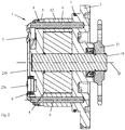
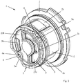
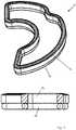
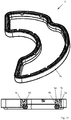
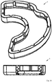
- the Figures 2 . 3 . 17 and 18 show pump inserts that can be used in a receiving housing, as in FIG. 1 shown.
- the pump in particular the pump insert 1, comprises a spring 5 which is shown herein in various embodiments.
- the pump or the pump insert 1 can have a seal 9, in particular an axial seal, arranged between an end wall 20c of a receiving housing 20 and a second housing part 3.
- the seal 9 is shown in various embodiments, in part combined with the spring 5.
- the pump or the pump insert 1 has a rotor 4, which is rotationally connected via a shaft-hub connection 30 with a pump shaft 10.
- the rotor 4 has as Guiding serving, in particular slot-shaped recesses.
- Each recess is a conveying element 13, in particular a wing assigned.
- the wing 13 is at its recess radially or away from the axis of rotation D of the rotor 4 and to the rotational axis D of the rotor 4 out, in particular guided with a single translational degree of freedom, back and forth, such. B. off FIG. 20 is recognizable.
- the wings 13 are rotated with the rotor 4.
- the pump 1 has an annular housing part, namely a cam ring 12.
- the cam ring 12 is enclosed between a first housing part 2 and a second housing part 3 and rotationally fixed with respect to the first and second housing part 2, 3.
- the annularly around the pump shaft 10 extending space which is surrounded by the inner circumference of the cam ring 12 and axially from the second and third housing part 2, 3 is limited, may also be referred to as the pump chamber 26.
- the rotor 4 and the wings 13 are arranged in the pump chamber 26.
- At least one delivery chamber 27, 28 is formed radially between the rotor 4 and the cam ring 12.
- the embodiment shown here comprises two delivery chambers 27, 28, namely a first delivery chamber 27 and a second delivery chamber 28 (FIG. FIG. 20 ).
- a conveyor cell 29 is formed in each case whose volume changes in dependence on the rotational position of the rotor 4 about its axis of rotation D. Since the pump has a plurality of wings 13, it also has a plurality of conveyor cells 29 correspondingly. In each of the delivery chambers 27, 28 there are a plurality of delivery cells 29.
- the vanes 13 and the rotor 4 form a first sealing gap with the first housing part 2 and a second sealing gap with the second housing part 3.
- the cam ring 12 and / or the wings 13 may be magnetized, so that the wings 13 abut due to magnetic force on the inner circumferential surface of the cam ring 12, in particular, even if the rotor 4 is not rotating. This allows an early build up of pressure at startup or cold start, ie, when the pump shaft 10 starts to rotate.
- the wings 13 due to the centrifugal force during the rotation of the rotor to the outside, ie away from the axis of rotation of the rotor 4 against the inner peripheral surface of the Hub ring 12 are pressed.
- the wings 13 and each of the wings 13 forms with the inner circumferential surface of the cam ring 12, a third sealing gap.
- the inner circumferential surface of the cam ring 12 has a contour which causes the wings 13 to extend at least once during one complete revolution of the rotor 4 (increase in volume of the conveyor cell 29) and retract once (volume reduction of the conveyor cell 29).
- the pump shown in the example is double-stroke, d. H. with two delivery chambers 27, 28, wherein the wings 13 per delivery chamber 27, 28 extend once and retract once when they are moved by rotation of the rotor 4 through the delivery chamber 27, 28.
- the wings 13 are caused to extend, retract, extend and retract in one full turn of the rotor 4, or in other words extend twice and retract twice.
- a conveyor cell 29 is formed in each case whose volume is increased or reduced by the extension and retraction of this conveyor cell 29 limited wings 13, namely in dependence on the contour of the inner peripheral surface of the cam ring 12th
- the pump insert 1 has a first outlet channel 3b and a second outlet channel 3c, wherein the first outlet channel 3b into a first pressure chamber 23b and a first delivery chamber 27 (FIG. FIG. 20 ) and thus connects the first delivery chamber 27 and the first pressure chamber 23b liquid-conducting together.
- the second outlet channel 3c opens into a second delivery chamber 28 and the second pressure chamber 23c, whereby it controls the second delivery chamber 28 (FIG. FIG. 20 ) and the second pressure chamber 23c fluid leading connects.
- the first and second outlet channels 3b, 3c each open into the region of its respective delivery chamber 27, 28, in which the volume of the delivery cells 29 decreases during the rotation of the rotor 4. This causes that in the conveyor cells 29 befindliches fluid such. As oil, are displaced by the outlet channels 3b, 3c.
- the pump insert 1 has a first inlet channel 2b and a second inlet channel 2c, wherein the first inlet channel 2b opens into the first delivery chamber 27 and a suction chamber 24 and thus fluidly connects the first delivery chamber 27 and the suction chamber 24, and wherein the second inlet channel 2c in the second delivery chamber 28 and the Suction chamber 24 opens and thus connects the second delivery chamber 28 and the suction chamber 24 liquid-conducting.
- the first and second inlet channels 2b, 2c respectively open into the region of its respective delivery chamber 27, 28, in which the volume of the delivery cells 29 increases during the rotation of the rotor 4. As a result, fluid is caused to be conveyed or sucked through the first and second inlet passages 2b, 2c into the enlarging feed cell 29.
- fluid, in particular liquid is sucked through the channel 2b, 2c in the increasing delivery cell 29 and transported to the area in which the outlet channel 3b, 3c opens, wherein the fluid from the then reducing conveyor cells 29 via the first outlet channel 3b and the second outlet channel 3c, respectively.
- the pump insert 1 comprises at least one positioning element 6, in the example shown two positioned elements 6.
- the positioning elements 6 are pins or pin-shaped.
- the positioning element 6 is firmly anchored in the first housing part 2.
- the first housing part 2 has a blind bore 2a into which the pin-shaped positioning element 6 is pressed with a first end.
- the pin-shaped positioning member 6 positions the second housing part 3 and the cam ring 12 with respect to their angular positions about the axis of rotation D relative to the first housing part 2.
- the second housing part 3 and the cam ring 12 have recesses, openings, holes or slots, preferably with a radial extent, through which the positioning element 6 extends.
- the cam ring 12 for this purpose has a bore 12a for the first positioning element 6 and a further bore 12a for the second positioning element 6.
- the second housing part 3 has a through hole through which the positioning element 6 extends.
- the positioning element 6 protrudes with its pin-shaped second end over the end face, which faces away from the pump chamber 26. This protruding portion of the positioning member 6 has a recess, such as. B.
- an annular groove 6 a or at least a part thereof, which extends over the circumference of the positioning element 6.
- a securing element or fastening element 5a of the spring 5 is arranged, which is in particular non-positively and / or positively secured to the positioning element 6 and in the annular groove 6a.
- the Fastener 5a prevents axial disintegration of the first housing part 2, the second housing part 3 and the cam ring 12, or in other words a removal of the second housing part 3 and the cam ring 12 of the positioning element 6.
- the spring 5 is captive on the pump insert. 1 , in particular the positioning elements 6 attached.
- the pump shaft 10 is rotatably mounted on the first and second housing part 2, 3, in particular by means of a respective sliding bearing.
- a pump shaft 10 mounted on both sides it can do without bearing in the second housing part 3 or only with the bearing in the first housing part 2, in particular when the pump insert 1 is double-stroke, d. H. two e.g. with respect to the axis of rotation D opposite conveying chambers 27, 28 has. The forces caused by the pressures in the delivery chambers 27, 28 transversely to the axis of rotation D can be canceled in the result in about.
- an outer structure such. B. an external toothing on the pump shaft 10 is formed, which is in a form-locking engagement with a corresponding internal structure, in particular internal toothing of the rotor 4 to form a shaft-hub connection 30.
- the outer diameter of the outer structure of the pump shaft 10 is greater than the diameter of the portion of the pump shaft 10 which is mounted in the first housing part 2 and / or in the second housing part 3.
- the pump shaft 10 is axially fixed between the first and second housing part 2, 3, d.
- the first housing part 2 has on its side facing away from the pump chamber 26 end face an annular pocket in which a shaft seal 11 is arranged, which is rotatably attached to the first housing part 2 and forms a sealing gap with the pump shaft 10.
- the shaft seal 11 seals the pump chamber 26 to the outside.
- the gear 21 is rotationally fixed on the pump shaft 10.
- the gear 21 can be driven by a chain, in turn, of z. As a crankshaft or other wave, the z. B. can be connected to an engine of the vehicle, is driven.
- the gear 21 has for its attachment to the pump shaft 10 z. As an internal thread, with which it is screwed with an external thread of the pump shaft 10 against a shoulder of the pump shaft 10. A torsion secured against rotation on the shaft 10 secures the gear 21 against unintentional release.
- the drive wheel 21 may be joined or attached to the pump shaft 10 by means of a press fit or other types of connection.
- the pump insert 1 is in the examples shown in a z. B. pot-shaped receiving housing 20, such. B. a housing pot used ( FIG. 1 ).
- the receiving housing 20 has a peripheral wall 20d, which surrounds one of the pump inserts 1 shown herein circumferentially.
- the receiving housing 20 has an end wall 20c, which is monolithically connected to the peripheral wall 20d, wherein the spring 5 is supported on the end wall 20c in particular axially, ie in the direction of the axis of rotation D.
- the pump insert 1 is between the end wall 20 c and an axial securing element, such.
- an axial securing element such as a screw, an axial securing ring or a lid held so that the spring 5 is stretched or remains, in particular, is stretched under pressure or remains.
- the axial securing element can rest on the first housing part 2 and / or hold the first housing part 2 displaceably on the receiving housing 20 along or in the direction of the axis of rotation D.
- the first pressure chamber 23b is formed, into which the pump promoted fluid (liquid) is promoted.
- the pressure chamber 23b is in turn by means of a channel (not shown) with a fluid consumer, such as. B. a lubricant consumer, in particular a transmission.
- a fluid consumer such as. B. a lubricant consumer, in particular a transmission.
- an annular seal 9 is arranged, which annularly surrounds the second pressure chamber 23c and seals it with respect to the first pressure chamber 23b.
- the seal 9 thus forms a wall of the first pressure chamber 23b and the second pressure chamber 23c.
- the second pressure chamber 23 c funded by the pump fluid is promoted.
- the second pressure chamber 23 c is in turn by means of a channel (not shown) with a fluid consumer, such as. B. a lubricant consumer connected.
- the seal 9 is arranged in a sealing groove or a sealing pocket of the second housing part 3, which annularly surrounds one end of the second outlet channel 3c, the groove base or the pocket bottom forming a sealing surface for the seal 9.
- the wall of the groove or pocket which surrounds the seal annularly has a distance from the end wall 20c, which is less than the height of the seal 9, in particular as the height of the first ring 9a, which will be described below.
- the first ring 9a in particular its material, or / and the smaller gap width between wall and end wall 20c, a gap extrusion of the seal 9 is prevented. Also by a support structure in the seal 9, a gap extrusion can be avoided.
- a suction chamber 24 is formed, from the fluid via the first delivery chamber 27 and the second Delivery chamber 28 is conveyed into the first pressure chamber 23b and the second pressure chamber 23c.
- the suction chamber 24 may, for. B. be connected by means of a channel with a reservoir for the fluid in which z. B. the fluid consumed by the consumer can flow back.
- the pressure in the pressure chambers 23b, 23c is increased with increasing speed, whereby the second housing part 3 in addition to the biasing force of the spring the cam ring 12 firmly clamped between the first and second housing part 2, 3.
- the first and second housing part 2, 3 and the cam ring 12 are sealed to each other.
- the connection between the Axialommeselement and the first housing part 2 is formed so strong that they Axialkraft on the Axialommeselement, as is effected by the pressure in the pressure chambers 23b, 23c, can resist, that is not dissolved.
- the axial securing element is a housing cover, which is fastened to the receiving housing 20 and on which the first housing part 2 is axially supported.
- spring 5 z As a spring 5 z. As a suitably designed Wellringfeder, a multi-corrugated spring washer, a hose or bow spring, a Nutringfeder, a metal O-ring or a metal C-ring in question. If the spring 5 is to be fastened to the positioning elements 6, the spring can have fastening elements 5a for their attachment to the positioning elements 6.
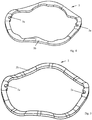
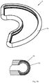
- a first embodiment of a spring 5 is shown, which is designed as a corrugated ring spring.
- the corrugated ring spring 5 has an annular spring structure 5b, which is corrugated over its circumference, that is, has a plurality of waves, ie wave crests and wave troughs.
- the waves can z. B. on the end wall 20c and the troughs rest on the second housing part 3.
- the wave height extends approximately parallel to the axis of rotation D.
- the spring 5 is made of a flat material, in particular punched out.
- the spring 5 has on its circumference a plurality of, here two, fastening elements 5a in the form of recesses open towards the inner circumference, which can be arranged in the annular groove 6a of a positioning element 6.
- the thickness of the flat material of the spring 5 is less than the groove width of the annular groove 6a.
- the spring 5 off FIG. 5 is identical to the spring 5 so far FIG. 4 ,
- the spring 5 off FIG. 4 has in addition on its inner circumference several inwardly projecting Abragungen. As a result, the stress curve in the spring during deformation comparatively or the spring preload and spring rate can be adapted to the requirements.
- the spring 5 off FIG. 6 essentially corresponds to the execution FIG. 5 , wherein the spring structure 5b from FIG. 6 more waves than the embodiment FIG. 5 has, that is more curled.
- the spring structure 5b has a positioning element 5e, which can engage in a corresponding recess of the second housing part 3 in order to secure the spring 5 in the correct position to the fastening elements 6.
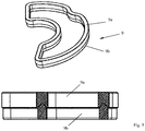
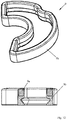
- FIG. 7 shows an annular spring 5, which has a plurality of tubular portions 5f over its circumference, in this example two tubular portions 5f. Between adjacent tubular sections 5f, a fastening element 5a and in particular a flat section 5g is arranged, in which the fastening element 5a is formed.
- the fastening element 5a is a recess open towards the inner circumference of the ring.
- the thickness of the flat portion 5g is smaller than the groove width of the annular groove 6a of the positioning member 6.
- the flat portion 5g can be formed by compressing and plastically deforming a previously continuous tubular portion 5f. In the example shown there are two fastening elements 5a and thus two flat sections 5g.
- the spring 5 has two tubular portions 5f connected at their ends via a flat portion 5g provided with a fixing member 5a, respectively.
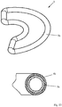
- FIG. 8 shows a spring 5, which is identical to the spring FIG. 7 is with the exception of the design of the tubular portions 5f.
- the execution FIG. 8 For example, instead of a tubular portion 5f, it has C-shaped portions 5h. Otherwise, the execution is off FIG. 7 directed.
- the C-shaped sections 5h each have a cross-sectionally open contour, namely a slot which extends over the circumference, in particular the inner circumference of the annular spring structure.
- the springs 5 or spring structures 5b from the FIGS. 4 to 8 are preferably formed of metal, in particular spring steel.
- the springs 5 may be coated or overmoulded, in particular with a plastic, such as.
- a plastic such as.
- FIG. 9 shows an annular seal 9, which comprises a first sealing ring 9a of a first material and a second sealing ring 9b of a second material.
- the first ring 9a and the second ring 9b may be integrally or integrally connected to each other, in particular cohesively.
- the first ring 9a serves for the stability of the annular seal 9, the second ring 9b serving primarily to ensure the sealing function.
- a material for the first ring 9a is plastic, in particular a thermoplastic or thermoplastics, which can be selected with the necessary properties.
- polytetrafluoroethylene is suitable whose core strength can be increased by pickled fibers, such as glass fibers, so that the axial seal can withstand significant pressures.
- ethylene-tetrafluoroethylene copolymer is considered as a material for the first ring, especially since this material can be processed well.
- Polyterephtalat is well suited for the intended purpose, since it can be well vulcanized with the sealing ring.
- polyamides, with or without fiberglass insert for the intended purpose are also suitable.
- the second ring 9b is preferably made of a plastic, in particular elastomeric or rubber-elastic material or elastomer, which is preferably well vulcanizable, does not tear and has no high notch sensitivities.
- the listed materials or materials are especially, but not only for the versions of the Figures 10 . 11 . 15 and 16 but may be used, for example, for all embodiments shown or described in the present application.
- the first ring 9a has a V-shaped groove extending over its circumference.
- the groove adapted to this groove shape formed by the second ring counterpart is arranged, which is connected in the groove with the first ring 9a, in particular vulcanized or glued.
- the first ring 9a also has a V-shaped groove extending over the circumference of the first ring 9a, and the second ring 9b is an O-ring having a circular cross-section.
- the second ring 9b is likewise arranged in the V-shaped groove and is in particular materially connected to the first ring 9a.
- the first ring 9a has a planar surface facing the second ring 9b, on which the O-ring-shaped second ring 9b rests and to which the second ring 9b is firmly bonded.
- FIG. 15 shows a first ring 9a, which has circumferentially about its annular periphery a step in which the second ring 9b, which is designed as an O-ring is received.
- the second ring 9b is materially connected to the first ring 9a.
- the second ring 9b is loosely inserted in the first ring 9a, in particular in the step-shaped shoulder.
- the front end of the seal which is opposite to the front end, which is formed by the second ring 9b, has at least one over the annular circumference of the first ring 9a circumferential groove on the groove is of a first circumferential, in particular inner groove wall 9c and a second circumferential, in particular outer groove wall 9d bordered.
- the first groove wall 9c is continuous over the circumference and is sealingly supported on its sealing surface, whereby the first pressure chamber 23b is sealed relative to the second pressure chamber 23c.
- the second groove wall 9d is provided over its circumference with a plurality of recesses, which make the second groove wall 9d liquid-permeable, whereby only the first groove wall 9c seals.
- the second groove wall 9d serves to support the seal on the sealing surface, so that the seal 9 does not tilt.
- the second groove wall 9d may be continuous over the circumference and the first groove wall 9c may be provided with the plurality of recesses, the above described being analogously applicable to this embodiment.
- the second groove wall 9d primarily for sealing and the first groove wall 9c serve primarily for support.
- FIG. 16 shows a seal 9, which consists only of a ring, such as. Example, from the material for the above-mentioned first ring 9a or the above-mentioned second ring 9b, depending on the expected pressure difference between the first pressure chamber 23b and the second pressure chamber 23c.
- a front end of the seal is configured with a sealing lip having an inclined inner surface which is inclined so that an internal pressure in the second pressure chamber 23c exerts a force on the sealing lip, which at least with a force component against the sealing surface of the second housing part 3 or the end wall 20c presses.
- On the inner circumference is a variety of z. B. along the height of the seal 5 or in the direction of the axis of rotation D extending recesses arranged z. B.
- the sealing lip opposite end face of the seal 9 may be flat or flat or as in FIG. 15 be designed.
- FIG. 12 shows an annular seal 9, which has a first ring 9a of the above-mentioned first material, alternatively of metal, in particular steel, which is coated or encapsulated over its surface substantially completely with plastic, in particular the elastomeric or rubber-elastic or thermoplastic material, whereby a second ring 9b is formed.
- FIG. 13 shows an annular seal 9, which has a first ring 9a, which is designed as an annular circulating tube.
- the ring 9a may, for.
- the annular circumferential tube 9 a may have a closed wall or z. B. be wound from a helical spring.
- the first ring 9a is coated or over-molded over its outer periphery with plastic, in particular the elastomeric or rubber-elastic or thermoplastic material, whereby a second ring 9b is formed, which surrounds the first ring 9a.
- the tube 9a off FIG. 13 can thus act as a spring and the coating or encapsulation 9b as a seal 9. The same applies mutatis mutandis to the execution FIG. 14 ,
- the execution FIG. 14 shows a first ring 9a, which is formed of a slotted tube or a C-shaped profile which rotates closed annular.
- the slot of the C-shaped profile or the slotted tube 9a faces the interior and thus the second pressure chamber.
- the first ring 9a is coated or overmoulded with plastic, in particular the elastomeric or rubber-elastic or thermoplastic material, resulting in a second ring 9b which at least partially surrounds the first ring 9a.
- FIG. 19 an embodiment of a spring 5 is shown, which is combined with a seal 9 and in the Figures 17 and 18 in connection with the pump insert 1 is shown.
- the spring 5 off FIG. 19 has an annular spring structure 5b with a first spring structure ring 5k, which extends in particular concentrically around the axis of rotation D.
- the spring structure 5b is formed of metal, in particular steel, which gives the spring 5 its essential spring property in the direction of the axis of rotation D.
- the annular spring structure 5b has a plurality of arms 5d protruding inward from the first spring structure ring 5k and distributed over its circumference, whose inwardly-contiguous ends are freely projecting.
- the arms 5c each have a contact surface 5d, with which they rest against the end wall 20c.
- the underside of the first spring structure ring 5k of the spring structure 5b abuts in the region on the second housing part 3, which is arranged in the direction of the axis of rotation D in axial alignment with the cam ring 12.
- the first spring structure ring 5k has two fastening elements 5a, which serve as continuous recesses, such. B. holes or slots are formed.
- the bore or the slot is surrounded by a wall at least over part of its circumference, which has a thickness extending along or in the direction of the axis of rotation D, which is smaller than the groove width of the annular groove 6a of the positioning element 6.
- a part of this wall in engage the annular groove 6a, whereby the spring 5 is secured captive on the at least one positioning element 6.
- the spring structure ring 5k for inserting the positioning members 6 into the through recesses of the fixing members 5a along an imaginary connecting line between the two fixing members 5a can be elastically compressed or pushed apart to allow fitting to the positioning members 6 and releasing a part of the wall by releasing to allow in the annular groove 6a.
- the spring structure 5b has a second spring structure ring 5j, which annularly surrounds the second pressure chamber 23c. Furthermore, the spring structure 5b has a third spring structure ring 5i, which extends around the axis of rotation D and is arranged within the first spring structure ring 5k, from which the arms 5d protrude.
- At least the second spring structure ring 5j, preferably and if present also the third spring structure ring 5i and optionally also the first spring structure ring 5k are coated or encapsulated with plastic, in particular the elastomeric or rubber-elastic or thermoplastic material, at least partially or completely, so that at least the in the direction of Rotary axis D facing ends of the second ring, which comprises the second spring structure ring 5j, and the third ring, which comprises the third Feder Designring 5i, are formed with a surface made of plastic, in particular the elastomeric or rubber-elastic or thermoplastic material. Further, the elastomeric or rubber-elastic or thermoplastic material separates the second pressure space 23c from the first pressure space 23b.
- the second ring with its encapsulation or coating can thus be defined as a seal 9.
- the third ring with its coating or encapsulation seals the bore of the second housing part 3, in which a portion of the pump shaft 10 is arranged, from the first pressure chamber 23b and the second pressure chamber 23c.
- the encapsulation or coating of the third ring is supported on the second housing part 3 and opposite to the housing wall 20c.
Landscapes
- Engineering & Computer Science (AREA)
- Mechanical Engineering (AREA)
- General Engineering & Computer Science (AREA)
- Details And Applications Of Rotary Liquid Pumps (AREA)
- Rotary Pumps (AREA)
Abstract
Description
- Die Erfindung betrifft eine Pumpe, insbesondere eine Verdrängerpumpe für eine Flüssigkeit, wie z. B. Öl. Die Pumpe kann z. B. als Flügelzellenpumpe oder Drehschieberpumpe, Innen- oder Außenzahnradpumpe, Pendelschieberpumpe oder Rollenzellenpumpe ausgestaltet sein. Die Pumpe eignet sich insbesondere für den Einbau in ein Fahrzeug, wie z. B. ein Kraftfahrzeug und/oder zur Versorgung eines Verbrauchers in einem Kraftfahrzeug. Der Verbraucher kann z. B. ein Verbrennungsmotor, ein Getriebe, wie z. B. ein Lenkgetriebe oder Automatikgetriebe sein. Ein erster Aspekt betrifft die Abstützung einer Feder, die zwischen einem Aufnahmegehäuse und einem in dem Aufnahmegehäuse eingesetzten Pumpeneinsatz wirkt. Ein zweiter Aspekt betrifft die Kombination einer Dichtung mit einer zwischen dem Aufnahmegehäuse und dem Pumpeneinsatz wirkenden Feder. Ein dritter Aspekt betrifft die Abdichtung von Druckräumen einer mehrhubigen Pumpe zueinander. Jeder der genannten Aspekte kann aber muss nicht notwendigerweise mit einem oder mehreren der anderen genannten Aspekte oder deren Weiterbildungen kombiniert werden.
- Aus der
WO 2013/185751 A1 ist eine sogenannte Cartridge-Pumpe bekannt, die eine Pumpenbaugruppe oder einen Pumpeneinsatz aufweist, der bzw. die im Wesentlichen aus einem Rotor, einem Hubring, einer Druckplatte, Pressstiften und einem Federelement besteht. Der Rotor ist zwischen der Druckplatte und der Seitenplatte drehbar aufgenommen und wird von dem Hubring, der ebenfalls zwischen der Druckplatte und der Seitenplatte angeordnet ist, umgeben. Mehrere Pressstifte, die in die Druckplatte axialfest eingepresst sind und die Seitenplatte und den Hubring durchdringen, sichern die Druckplatte, die Seitenplatte und den Hubring dreh- und axialfest zueinander. An der von dem Rotor wegweisenden Stirnseite der Druckplatte ist das Federelement an der Druckplatte befestigt. Der Pumpeneinsatz ist in ein topfförmiges Gehäuse eingesetzt, wobei sich das Federelement an dem Boden oder einer Stirnwand des topfförmigen Gehäuses abstützt. Das Gehäuse wird durch einen Gehäusedeckel geschlossen, der den Pumpeneinsatz in seiner Einbauposition hält. Das Federelement stützt sich mit zwei Federzungen an einer Kaltstartplatte ab, die sich wiederum an der Druckplatte 17 abstützt. Die Pumpe weist eine zwischen der Stirnwand und der Druckplatte angeordnete Dichtung auf, welche einen ersten Druckraum und einen zweiten Druckraum zueinander abdichtet, wobei die Druckräume zwischen der Stirnwand und der Druckplatte angeordnet sind. Die Dichtung ist ein von dem Federelement separates Teil. - Die
EP 0 415 089 A2 beschreibt eine Axialdichtung mit einem Sperrring und einem einstückig daran befestigten Dichtring. Der Sperrring besteht aus einem Thermoplast mit extrusionsfestem Kern und etwas nachgiebiger Oberfläche, die aufgrund des zusammengepressten Dichtrings und des Öldrucks gegen die Wandung des abzudichtenden Spaltes gepresst wird. Ein in einem topfförmigen Pumpengehäuseteil angeordneter Pumpeneinsatz weist eine Druckplatte auf, wobei die Axialdichtung zwischen der Druckplatte und einer Stirnwand des Pumpengehäuseteils angeordnet ist. Eine von der Axialdichtung separate Ventilfeder wirkt zwischen einer Stirnwand des Pumpengehäuseteils und der Druckplatte. Die Ventilfeder stützt sich über ein Ventil an der Druckplatte ab. Das Ventil stützt sich zentrisch, d. h. im Bereich einer Drehachse eines Rotors des Pumpeneinsatzes an der Druckplatte ab. DieEP 0 415 089 A2 zeigt Ausführungen mit einer Axialdichtung oder mehreren Axialdichtungen, wobei die Axialdichtung oder Axialdichtungen einen saugseitigen Bereich von einem druckseitigen Bereich abdichten. Der saugseitige Bereich und der druckseitige Bereich sind zwischen der Stirnwand und der Druckplatte angeordnet. - Dem ersten Aspekt liegt die Aufgabe zugrunde, eine durch die Federkraft bewirkte nachteilige Verformung des Pumpendeckels und/oder der Stirnwand des Aufnahmegehäuses möglichst zu vermeiden. Dem zweiten Aspekt liegt die Aufgabe zugrunde, die Montierbarkeit des Pumpeneinsatzes in das Aufnahmegehäuse zu erleichtern. Dem dritten Aspekt liegt die Aufgabe zugrunde, eine platzsparende Pumpe anzugeben, welche verschiedene Fluidkreisläufe mit Druckfluid versorgen kann.
- Die Erfindung geht von einer Pumpe, insbesondere Verdrängerpumpe, wie z. B. Flügelzellen- oder Drehschieberpumpe oder einer Zahnradpumpe oder einer Pendelschieberpumpe oder einer Rollenzellenpumpe aus. Die Pumpe umfasst ein Aufnahmegehäuse, welches einen topfförmigen Aufnahmeraum mit einer Stirnwand und einer Umfangswand bildet, und einen Pumpeneinsatz, der in dem Aufnahmeraum insbesondere als separat von dem Aufnahmegehäuse handhabbare Einheit angeordnet oder eingesetzt ist. Der Pumpeneinsatz kann sich an der Umfangswand des topfförmigen Aufnahmeraums abstützen oder zentrieren oder mit der Umfangswand mindestens einen über den Umfang umlaufenden Dichtspalt bilden. Der Pumpeneinsatz kann somit von der Umfangswand geführt werden.
- Der Pumpeneinsatz umfasst ein Gehäuse, welches einen Pumpenraum einfasst. In dem Pumpenraum kann ein Rotor um eine Drehachse relativ zu dem Gehäuse drehbar angeordnet sein. Die Pumpe kann den Rotor und zumindest ein erstes Gehäuseteil, insbesondere einen ersten Gehäusedeckel und ein zweites Gehäuseteil, insbesondere einen zweiten Gehäusedeckel, zwischen denen der Rotor um eine Drehachse relativ zu dem ersten und zweiten Gehäuseteil drehbar angeordnet ist, umfassen. Der Rotor kann unmittelbar oder mittelbar drehmomentübertragend mit einer Pumpenwelle verbunden oder verbindbar sein, wie z. B. über eine Welle-Nabe-Verbindung. Wenn die Pumpenwelle relativ zu dem ersten und zweiten Gehäuseteil gedreht wird, dreht sich der Rotor mit. Der Rotor weist Ausnehmungen, insbesondere Führungen, wie z. B. schlitzförmige Ausnehmungen oder Führungen, auf, in denen Förderelemente, wie z. B. Flügel, Schieber oder Rollen, radial zur Drehachse bewegbar, insbesondere verschiebbar aufgenommen sind. Die Förderelemente sind so von dem Rotor aufgenommen oder gelagert, dass sie sich mit dem Rotor um seine Drehachse mitdrehen. Insbesondere ist jedes der Förderelemente in seiner Führung mit einem einzigen translatorischen Freiheitsgrad verschiebbar gelagert.
- Die Pumpenwelle kann sich durch das Gehäuse erstrecken und um die Drehachse drehbar an dem Gehäuse gelagert sein, wie z. B. mit einem ersten Abschnitt an dem ersten Gehäuseteil und mit einem zweiten Abschnitt an dem zweiten Gehäuseteil. Zwischen dem ersten Abschnitt und dem zweiten Abschnitt der Pumpenwelle kann eine Außenstruktur für die Welle-Nabe-Verbindung gebildet sein. Der Rotor und die Pumpenwelle können mittels einer z. B. geradverzahnten Welle-Nabe-Verbindung verdrehfest verbunden sein. Die Welle-Nabe-Verbindung weist eine Innenverzahnung mit mehreren Zähnen und eine in die Innenverzahnung eingreifende Außenverzahnung mit mehreren Zähnen auf.
- Zwischen dem ersten Gehäuseteil und dem zweiten Gehäuseteil kann ein drittes Gehäuseteil, nämlich ein Hubring, angeordnet sein. Der Hubring umgibt den Rotor über seinen Umfang. Der Hubring kann ein von dem ersten und zweiten Gehäuseteil separates Teil sein. Alternativ kann der Hubring ein von dem ersten Gehäuseteil gebildeter Abschnitt des ersten Gehäuseteils oder ein von dem zweiten Gehäuseteil gebildeter Abschnitt des zweiten Gehäuseteils sein. Das erste Gehäuseteil oder das zweite Gehäuseteil oder beide können den Rotor und insbesondere seine Förderelemente umgeben, wie z. B. ringförmig umgeben, wenn der Hubring Teil des ersten oder zweiten Gehäuseteils ist.
- Das erste Gehäuseteil, das zweite Gehäuseteil und der Hubring fassen ein und begrenzen eine Pumpenkammer, in der der Rotor und die Förderelemente angeordnet sind. Radial zwischen dem Hubring und dem Rotor, der zwischen dem ersten und dem zweiten Gehäuseteil drehbar eingefasst ist, ist mindestens eine Förderkammer gebildet, wie z. B. eine erste Förderkammer und eine zweite Förderkammer bei einer doppelhubigen Pumpe.
- Zwischen benachbarten Förderelementen ist jeweils eine Förderzelle gebildet, die umfangsseitig von einer Innenumfangsfläche des Hubrings und in Richtung der Drehachse von dem ersten Gehäuseteil auf einer Seite und von dem zweiten Gehäuseteil auf der anderen Seite begrenzt wird und deren Volumen sich in Abhängigkeit von der Drehposition des Rotors um seine Drehachse verändert. Die Pumpe weist eine Vielzahl von Förderelementen und somit eine insbesondere gleiche Vielzahl von Förderzellen auf, die zwischen den Förderelementen gebildet sind.
- Der Innenumfang des Hubrings weist eine Kontur auf, an welcher die Förderelemente bei einer Drehung des Rotors entlanggleiten. Die Kontur ist insbesondere so ausgebildet, dass sich die Volumina der aufgrund der Drehung des Rotors durch die Förderkammer bewegenden Förderzellen zunächst vergrößern und anschließend verkleinern. Bei einer vollständigen Umdrehung des Rotors werden die Förderelemente zumindest einmal von der Drehachse weg und zur Drehachse hin bewegt. Die Pumpe kann z. B. doppelhubig, d. h. mit einer ersten Förderkammer und einer zweiten Förderkammer ausgebildet sein, die von den Förderelementen bzw. den Förderzellen bei einer vollen Umdrehung jeweils einmal durchlaufen werden. D. h., dass die Förderelemente bei einer vollständigen Umdrehung abwechselnd zweimal von der Drehachse weg und zweimal zu der Drehachse hinbewegt werden. Während einer Drehung des Rotors findet zunächst eine Volumenvergrößerung einer Förderzelle und anschließend eine Volumenverkleinerung dieser Förderzelle statt.
- Die Pumpe oder der Pumpeneinsatz kann mindestens einen Einlasskanal aufweisen, der in den Bereich der Förderkammer mündet, in dem die Volumenvergrößerung der Förderzelle stattfindet, und mindestens einen Auslasskanal aufweisen, der in den Bereich der Förderkammer mündet, in dem die Volumenverkleinerung dieser Förderzelle stattfindet. Durch die Volumenvergrößerung der Förderzelle wirkt der mindestens eine Einlasskanal als Saugkanal. Durch die Volumenverkleinerung wirkt der mindestens eine Auslasskanal als Druckkanal. Eine einhubige Pumpe kann z. B. einen Einlasskanal und einen Auslasskanal aufweisen. Eine doppelhubige Pumpe kann z. B. einen gemeinsamen Einlasskanal für die erste und zweite Förderkammer und einen ersten Auslasskanal für die erste Förderkammer und einen davon separaten zweiten Auslasskanal für die zweite Förderkammer aufweisen. In einer Alternative kann der Pumpeneinsatz einen ersten Einlasskanal für die erste Förderkammer und einen davon separaten zweiten Einlasskanal für die zweite Förderkammer und einen ersten Auslasskanal für die erste Förderkammer und einen davon separaten zweiten Auslasskanal für die zweite Förderkammer oder einen gemeinsamen Auslasskanal für die erste und zweite Förderkammer aufweisen. Mit dem über die erste Förderkammer geförderten Fluid können z. B. andere oder die gleichen Verbraucher versorgt werden als mit dem über die zweite Förderkammer geförderten Fluid. Bei der Versorgung unterschiedlicher Verbraucher können unterschiedliche Druckniveaus zwischen dem ersten Auslasskanal und dem zweiten Auslasskanal bzw. zwischen dem ersten Druckraum, in den der erste Auslasskanal mündet, und dem zweiten Druckraum, in den der zweite Auslasskanal mündet, entstehen. Die Förderelemente und/oder der Rotor bilden mit dem ersten Gehäuseteil und dem zweiten Gehäuseteil jeweils einen Druckspalt. Der mindestens eine Einlasskanal kann mit einem Fluidvorratsbehälter, wie z. B. einem Ölbehälter verbunden sein oder werden, insbesondere in Fluidverbindung stehen. Z. B. kann der mindestens eine Saugkanal in einen Saugraum münden, der z. B. zwischen dem Aufnahmegehäuse und dem Pumpeneinsatz gebildet sein kann, insbesondere zwischen der Umfangswand des Aufnahmegehäuses und dem Pumpeneinsatz, wie z. B. dem Hubring. Der mindestens eine Auslasskanal kann mit mindestens einem Fluidverbraucher verbunden sein, wie z. B. mit einem Getriebe in Fluidverbindung stehen.
- Der Pumpeneinsatz kann mindestens ein Positionierelement aufweisen, welches das zweite Gehäuseteil bezüglich seiner Winkelposition um die Drehachse relativ zu dem ersten Gehäuseteil positioniert. Das mindestens eine Positionierelement kann von dem ersten Gehäuseteil gebildet sein, insbesondere einstückig oder monolithisch. Alternativ kann das mindestens eine Positionierelement als ein von dem ersten Gehäuseteil separates Teil gebildet sein, welches in dem ersten Gehäuseteil verankert ist. Z. B. kann das Positionierelement in das erste Gehäuseteil eingeschraubt oder eingepresst, d. h. formschlüssig und/oder kraftschlüssig verankert sein. Alternativ oder zusätzlich kann das mindestens eine Positionierelement in dem ersten Gehäuseteil stoffschlüssig verankert, wie z. B. verklebt, verlötet oder verschweißt sein. Das erste Gehäuseteil kann je Positionierelement eine Bohrung aufweisen, in der ein Ende des Positionierelements eingefügt und dadurch in den ersten Gehäuseteil verankert ist. Z. B. können zwei, drei, vier oder noch mehr Positionierelemente vorgesehen sein.
- Das mindestens eine Positionierelement kann insbesondere stiftförmig oder zylindrisch sein. Z. B. kann das dem verankerten Ende gegenüberliegende Ende des Positionierelements den gleichen Außendurchmesser wie das verankerte Ende aufweisen.
- Das zweite Gehäuseteil und insbesondere auch der Hubring können um die Drehachse verdrehgesichert an dem mindestens einen Positionierelement gelagert sein. Das mindestens eine Positionierelement kann sich durch eine je Positionierelement vorgesehene Ausnehmung des zweiten Gehäuseteils, wie z. B. durch eine Bohrung oder Durchgangsbohrung, erstrecken. Das mindestens eine Positionierelement kann sich z. B. durch eine Ausnehmung des Hubrings erstrecken, die z. B. als Bohrung, Langloch oder dergleichen ausgebildet sein kann.
- Insbesondere kann das mindestens eine Positionierelement mit seinem Ende, das dem im ersten Gehäuseteil verankerten Ende gegenüberliegt, aus dem zweiten Gehäuseteil ragen, insbesondere von der Stirnseite des zweiten Gehäuseteils ragen, welche der Stirnseite gegenüberliegt, die zu dem Rotor weist oder welche zu der Stirnwand des Aufnahmegehäuses weist.
- Die Pumpe oder der Pumpeneinsatz kann eine Feder aufweisen, die sich z. B. an dem zweiten Gehäuseteil und an dem Boden oder der Stirnwand des Aufnahmegehäuses abstützt. Das Aufnahmegehäuse kann wie gesagt z. B. topfförmig sein. Die Umfangswand des Aufnahmegehäuses kann sich um die Drehachse des Rotors erstrecken. Die Stirnwand ist stirnseitig der Umfangswand angeordnet, so dass das Aufnahmegehäuse topfförmig ist. Die zwischen der Stirnwand und den Pumpeneinsatz gespannte Feder trachtet, den Pumpeneinsatz, insbesondere das zweite Gehäuseteil von der Stirnwand des Aufnahmegehäuses wegzudrücken.
- Ein Herausfallen des Pumpeneinsatzes aus dem Aufnahmegehäuse wird z. B. durch einen Deckel oder ein Axialsicherungselement verhindert, wobei die beim Einsetzen gespannte Feder den Pumpeneinsatz, insbesondere das erste Gehäuseteil gegen das Axialsicherungselement oder den Deckel drückt, wobei das Axialsicherungselement oder der Deckel verhindert, dass sich die Feder entspannt. Das Axialsicherungselement kann z. B. ringförmig sein und in einer Ringnut, die am vorzugsweise zylindrischen Umfang des Aufnahmegehäuses gebildet wird, eingesetzt sein. Das Axialsicherungselement kann von einem Deckel gebildet sein, der die Öffnung zumindest teilweise oder vollständig verschließt.
- Die zwischen dem Pumpeneinsatz und der Stirnwand gespannte Feder übt eine von der Stirnwand wegweisende und insbesondere entlang, d.h. in Richtung der Drehachse des Rotors wirkende Kraft auf das zweite Gehäuseteil aus, welches dadurch gegen den Hubring gedrückt wird, wobei der Hubring gegen das erste Gehäuseteil gedrückt wird. Das Widerlager hierfür bildet der Deckel oder das Axialsicherungselement. Durch die Federkraft wird der Hubring in Bezug auf das erste und zweite Gehäuseteil axial abgedichtet, wodurch sich beim Anlaufen der Pumpe Druck in der Förderkammer oder den Förderkammern aufbauen kann.
- Die Feder kann insbesondere verliersicher an dem Pumpeneinsatz befestigt sein, insbesondere an dem mindestens einen Positionierelement oder dem zweiten Gehäuseteil. Die Feder kann z. B. mit dem Positionierelement oder dem zweiten Gehäuseteil formschlüssig, insbesondere verschnappt oder kraftschlüssig verbunden sein, so dass die Feder an dem mindestens einen Positionierelement oder dem zweiten Gehäuseteil gehalten wird und sich vorzugsweise an dem zweiten Gehäuseteil abstützt oder abstützen kann. Bevorzugt ist, dass die Feder um die Drehachse verdrehgesichert, insbesondere form- oder/und kraftschlüssig, an dem mindestens einen Positionierelement oder dem zweiten Gehäuseteil befestigt ist. Die Feder kann mindestens ein Befestigungselement aufweisen oder bilden, insbesondere am oder im Bereich eines Abstützabschnitts, mit dem sich die Feder an dem zweiten Gehäuseteil oder an einem Teil, welches sich mittelbar oder unmittelbar an dem zweiten Gehäuseteil abstützt, abstützt. Z. B. kann das mindestens eine Befestigungselement als Abstützabschnitt dienen oder je Abstützabschnitt ein Befestigungselement vorgesehen sein. Mittels des Befestigungselements kann die Feder an dem mindestens einen Positionierelement oder dem zweiten Gehäuseteil befestigbar oder befestigt sein. Das Befestigungselement, welches z. B. für eine formschlüssige Verbindung mit dem ihm zugeordneten Positionierelement ausgestaltet ist, kann mit dem Positionierelement verschnappt sein.
- Das mindestens eine Positionierelement kann eine Ausnehmung, wie z. B. eine Ringnut über seinen Umfang aufweisen, in welche das mindestens eine Befestigungselement der Feder eingreift. Eine derartige Ringnut kann als Einstich ausgebildet sein. Z. B. kann das mindestens eine Befestigungselement sicherungsscheibenförmig oder seegerringförmig ausgestalt sein, ähnlich wie Sicherungsscheiben für Wellen nach DIN 6799 oder Sicherungsringe für Wellen nach DIN 471, insbesondere mit dem Unterschied, dass sie von der Feder gebildet werden, nämlich an dem Abstützabschnitt angeformt sein können.
- In alternativen Ausführungsformen kann das Sicherungselement, insbesondere die z. B. nach DIN 6799 ausgestaltete Sicherungsscheibe oder der nach DIN 471 ausgestaltete Seegerring tatsächlich eine Scheibe oder ein Ring sein, d. h. nicht an der Feder angeformt sein und z. B. nur dazu dienen, dass das zweite Gehäuseteil axial nicht von dem Positionierelement abziehbar ist. In dieser Ausführungsform kann die Feder an dem zweiten Gehäuseteil oder an dem Sicherungselement befestigt oder zwischen dem Sicherungselement und dem zweiten Gehäuseteil eingefasst sein, wobei das Befestigungselement der Feder auf das Positionierelement aufgesteckt sein kann. In alternativen Ausführungsformen kann das Positionierelement z. B. mit einem Kopf ausgestaltet sein, wobei das zweite Gehäuseteil zwischen dem ersten Gehäuseteil und dem Kopf eingefasst ist, so dass verhindert wird, dass das zweite Gehäuseteil von dem ersten Gehäuseteil bzw. von dem Positionierelement abgezogen werden kann. In diesen Ausführungsformen kann die Feder an dem zweiten Gehäuseteil oder an dem Kopf befestigt oder zwischen dem Kopf und dem zweiten Gehäuseteil eingefasst sein, wobei das Befestigungselement der Feder auf das Positionierelement aufgesteckt sein kann.
- In weiteren Ausführungsformen kann die Ausnehmung eine sich über den Umfang des zylindrischen oder stiftförmigen Positionierelements erstreckende Ringnut sein, welche eine entlang der Längsachse des Positionierelements erstreckte Breite aufweist, die so bemessen ist, dass das Befestigungselement der Feder mit einem Spiel entlang der Längsachse in der Ringnut aufgenommen ist. Hierdurch kann sichergestellt werden, dass sich der Abstützabschnitt oder der Befestigungsabschnitt der Feder an dem zweiten Gehäuseteil und nicht an einer Nutflanke der Ringnut abstützt.
- In Ausführungsformen, in denen die Feder am zweiten Gehäuseteil befestigt ist, kann das zweite Gehäuseteil an einer Innenumfangsfläche oder einer Außenumfangsfläche eine um die Drehachse des Rotors zumindest teilweise oder vollständig umlaufende Nut aufweisen, die nach innen oder nach außen hin offen ist, wobei die Feder, d.h. ein oder mehrere Abschnitte der Feder in der Nut an dem zweiten Gehäuseteil befestigt, insbesondere von der Nut eingefasst ist. Die Nutbreite ist etwas größer als die Dicke der Abschnitte der Feder, die in der Nut zur Befestigung angeordnet werden. Zum Beispiel kann die Feder zum Einfügen in die Nut seitlich elastisch zusammengedrückt werden, wobei die Feder in unmittelbarer Nähe der Nut platziert und anschließend losgelassen wird. Durch die Elastizität der Feder nimmt diese wieder ihre ursprüngliche Form ein, wodurch die Feder bzw. Abschnitte davon in die Nut einrasten und die Feder verliersicher an dem zweiten Gehäuseteil befestigen. Die Feder kann zum Beispiel im entspannten Zustand eine ovale Form oder Abragungen, welche die besagten Abschnitte bilden, aufweisen, wobei die umlaufende Nut oder Ringnut sich kreisförmig um die Drehachse erstreckt.
- Die Pumpe kann eine Pumpenwelle aufweisen, welche verdrehfest mit dem Rotor verbunden und um die Drehachse drehbar ist. Die Pumpenwelle kann zumindest in dem ersten Gehäuseteil drehbar gelagert sein. Zusätzlich kann die Pumpenwelle in dem zweiten Gehäuseteil drehbar gelagert sein, insbesondere in einer sackförmigen Ausnehmung oder in einer durchgehenden Ausnehmung, insbesondere Bohrung, durch das zweite Gehäuseteil. Die sackförmige Ausnehmung hat den Vorteil, dass die Pumpenkammer zu der von der Pumpenkammer wegweisenden Stirnseite des zweiten Gehäuseteils abgedichtet ist. Die durchgehende Ausnehmung hat den Vorteil, dass sie einfach zu Fertigen ist und eine höhere Stabilität gewährleistet. Das oder die Lager können Gleit- oder Wälzlager sein.
- Die Pumpenwelle kann eine Struktur, insbesondere eine Außenverzahnung für eine Welle-Nabe-Verbindung mit dem Rotor aufweisen. Der Durchmesser der Struktur kann größer als der Innendurchmesser des ersten Gehäuseteils und/oder des zweiten Gehäuseteils oder der Lager sein. Die Struktur ist somit zwischen dem ersten Gehäuseteil und dem zweiten Gehäuseteil entlang, d.h. in Richtung der Drehachse eingefasst. Dadurch wird bewirkt, dass die Welle nicht aus dem fertig montierten Pumpeneinsatz herausgezogen werden kann.
- Insbesondere das erste Gehäuseteil, das zweite Gehäuseteil, der Hubring, der Rotor, die Förderelemente, die Positionierelemente, die Feder und die Pumpenwelle können im Wesentlichen den Pumpeneinsatz, der als Einheit handhabbar ist, bilden. Dadurch, dass die Feder an dem mindestens einen Positionierelement befestigt wird, kann ein Auseinanderfallen des Pumpeneinsatzes vermieden werden. Die Befestigungsabschnitte der Feder und/oder die von der Feder separaten Sicherungselemente bewirken eine axiale Wellensicherung, so dass der Pumpeneinsatz nicht auseinanderfällt.
- Durch die einfache Handhabung des Pumpeneinsatzes kann dieser in das Aufnahmegehäuse, das z. B. von einem Getriebegehäuse für ein Kraftfahrzeug gebildet sein kann, aufgenommen werden bzw. in das Aufnahmegehäuse eingesetzt werden, z. B. über eine der Stirnwand gegenüberliegende Öffnung des Aufnahmegehäuses.
- In weiteren Ausführungsformen kann zwischen dem zweiten Gehäuseteil und dem Aufnahmegehäuse, insbesondere Umfangswand, eine (zweite) Dichtung, insbesondere ein Dichtring angeordnet sein, welche einen Druckraum, der im Wesentlichen zwischen der Stirnwand und dem zweiten Gehäuseteil gebildet ist, in Bezug auf einen Saugraum, der zwischen der Umfangswand und dem ersten Gehäuseteil und/oder dem Hubring gebildet ist, abdichtet. Beispielsweise kann der Druckraum mittels des mindestens einen Auslasskanals mit der mindestens einen Förderkammer verbunden sein.
- Zwischen dem ersten Gehäuseteil und dem Aufnahmegehäuse, insbesondere der Umfangswand, kann eine (erste) Dichtung, insbesondere ein Dichtring angeordnet sein, wobei der Saugraum zwischen der ersten und zweiten Dichtung angeordnet ist. Die erste Dichtung kann die Abdichtung des Saugraums nach außen oder zur Öffnung des Aufnahmegehäuses hin bewirken.
- Dadurch, dass der mindestens eine Druckraum zwischen der Stirnwand und dem zweiten Gehäuseteil angeordnet ist, wirkt das zweite Gehäuseteil wie ein Kolben, der bei Druckerhöhung im Druckraum die Kraft entlang oder in Richtung der Drehachse auf das Axialsicherungselement oder den Deckel erhöht und somit auch die Teile des Pumpeneinsatzes, insbesondere das erste Gehäuseteil, das zweite Gehäuseteil und den Hubring, dichtend aneinanderdrückt und zwar mit einer steigenden Kraft bei steigendem Förderdruck und insbesondere zusätzlich zu der Kraft der vorgespannten Feder.
- Nach dem ersten Aspekt stützt sich die zwischen dem Aufnahmegehäuse und dem zweiten Gehäuse federnd angeordnete, insbesondere gespannte Feder zum zweiten Gehäuseteil hin im Wesentlichen in einem Bereich ab, der in Richtung der Drehachse des Rotors in einer axialen Flucht mit dem Hubring angeordnet ist, und dadurch, d. h. durch die Abstützung in Flucht mit dem Hubring, das zweite Gehäuseteil gegen den Hubring drückt. In einer Flucht bedeutet, in einer gedachten axialen Verlängerung der Wand des Hubrings entlang oder in Richtung der Drehachse. Bei der
WO 2013/185751 A1 stützt sich das Federelement mit seinen zwei Federzungen an einer Kaltstartplatte und in einem Bereich ab, der außerhalb der axialen Flucht mit dem Hubring liegt, nämlich innerhalb der Innenkontur des Hubrings. Durch den radialen Abstand zwischen dem Bereich, an dem sich die Feder abstützt und dem Hubring entsteht ein Moment, welches zu einer, wenngleich auch nur leichten Verformung des Deckels führt, wodurch jedoch die Reibung des Rotors am Deckel zunimmt bzw. alternativ der Dichtspalt verhältnismäßig groß gebildet sein muss, wodurch der Wirkungsgrad der Pumpe abnimmt. Bei derEP 0 415 089 A2 stützt sich die Ventilfeder über das Ventil an der Druckplatte ab, wobei der Bereich ebenfalls innerhalb der Innenabmessungen des Hubrings liegt, wodurch es ebenfalls zu kleinen Verformungen im Deckel kommen kann. Die Abstützung nach dem ersten Aspekt verhindert solche Verformungen, wodurch der Wirkungsgrad der Pumpe erhöht wird. - Insbesondere kann die Feder eine Federstruktur aus Metall, insbesondere aus Stahl oder Federstahl aufweisen, wobei die Federstruktur aus Metall der Feder ihre wesentliche Federeigenschaft entlang oder in Richtung der Drehachse verleiht. Dies ist so zu verstehen, dass die Feder z. B. mit einem anderen Material beschichtet oder umspritzt sein kann, welches ebenfalls eine Federeigenschaft aufweist, wenngleich diese gegenüber der Federstruktur aus Metall vernachlässigbar ist.
- Die Feder kann sich mittelbar oder unmittelbar an dem zweiten Gehäuseteil abstützen. Beispielsweise kann ein Zwischenteil zwischen dem zweiten Gehäuseteil und der Feder angeordnet sein, wobei sich die Feder an dem Zwischenteil abstützt. Insbesondere kann sich das Zwischenteil an dem zweiten Gehäuseteil abstützen, vorzugsweise ebenfalls in einem Bereich, der in Richtung der Drehachse in einer axialen Flucht mit dem Hubring angeordnet ist.
- Das Zwischenteil kann z. B. eine sogenannte Kaltstartplatte oder eine plattenförmige Struktur, wie z. B. ein perforiertes (Metall-) Blech oder eine Siebstruktur, aufweisen oder sein. Das Zwischenteil kann z. B. zwischen der Feder und dem zweiten Gehäuseteil eingefasst oder angeordnet sein und/oder an dem mindestens einen Positionierelement gehalten oder befestigt sein, wie z. B. je Positionierelement, an dem es befestigt ist, eine Ausnehmung oder Bohrung aufweisen, durch welche sich das betreffende Positionierelement erstreckt. Das Zwischenteil kann mindestens einen Bereich mit der siebförmigen Struktur oder mindestens einen perforierten Bereich aufweisen, wie z. B. einen einzigen, zwei oder noch mehr solche Bereiche. Das Zwischenteil ist insbesondere so angeordnet, dass der mindestens eine Bereich von der aus der mindestens einen Förderkammer geförderten Flüssigkeit durchflossen wird. Durch den - wenngleich auch z.B. geringen - Strömungswiderstand, der durch den mindestens einen Bereich beim Durchströmen verursacht wird, steigt der Druck anströmungsseitig, d. h., auf der Seite des Zwischenteils, welche von der Flüssigkeit aus der mindestens einen Förderkammer angeströmt wird.
- Anströmungsseitig des Zwischenteils weist der Pumpeneinsatz, insbesondere das zweite Gehäuseteil, mindestens einen Verbindungskanal auf, der die Unterflügelkammern, d. h. die Kammern, die in den Schlitzen gebildet sind, in denen die Flügel geführt sind, und sich radial zwischen einen Ende des jeweiligen Flügels und dem Grund des jeweiligen Schlitzes erstrecken, mit dem aus der mindestens einen Förderkammer geförderten Flüssigkeit versorgt. Der durch den durchflossenen Bereich des Zwischenteils erzeugte Staudruck bewirkt ein schnelleres Ausfahren der Flügel beim Kaltstart und somit generell einen schnelleren Druckaufbau durch die Pumpe. Das Zwischenteil und/oder die Feder, an der sich das Zwischenteil beispielsweise nachgiebig abstützen kann, kann alternativ oder zusätzlich zu der siebförmigen oder perforierten Struktur so flexibel nachgiebig gestaltet sein, dass das Zwischenteil beim Erreichen eines Grenzdrucks zumindest teilweise von dem zweiten Gehäuseteil abhebt, wodurch Flüssigkeit aus der Förderkammer durch einen dadurch gebildeten Spalt zwischen Zwischenteil und zweitem Gehäuseteil fließen kann.
- Z. B. kann sich die Feder, insbesondere mit ihrem zum Aufnahmegehäuse hin bzw. zur Stirnwand weisenden Ende, im Wesentlichen in einem Bereich an dem Aufnahmegehäuse, insbesondere an der Stirnwand, abstützen, der in Richtung der Drehachse in einer axialen Flucht mit dem Hubring angeordnet ist. Ein Vorteil hierbei ist, dass eine Verformung der Stirnwand durch die Federkraft vermieden kann. Ein weiterer Vorteil ist, dass der Querschnitt, den die Feder insbesondere ringförmig umgibt, einen verhältnismäßig großen Durchmesser aufweist, insbesondere in etwa zumindest den Innendurchmesser oder den kleinsten Innendurchmesser des Hubrings. Hierdurch wird vorteilhaft erreicht, dass der von der Feder umgebene Querschnitt relativ groß ist und somit die Möglichkeit bietet, eine insbesondere ringförmige Dichtung, insbesondere Axialdichtung zwischen dem zweiten Gehäuseteil und der Stirnwand des Aufnahmegehäuses dichtend anzuordnen, um z. B. einen zweiten Druckraum gegenüber einem ersten Druckraum abzudichten. Demnach kann zwischen dem zweiten Gehäuseteil und der Stirnwand des Aufnahmegehäuses ein Dichtelement angeordnet sein, welches den Druckraum insbesondere ringförmig umgibt. Insbesondere kann die Feder ringförmig sein und einen Druckraum, insbesondere einen ersten Druckraum, der über den vom zweiten Gehäuseteil gebildeten Auslasskanal, insbesondere den ersten Auslasskanal, mit der Förderkammer, insbesondere der ersten Förderkammer, verbunden ist, zumindest teilweise umgeben. Insbesondere kann die Feder in dem ersten Druckraum angeordnet sein.
- Insbesondere kann die Dichtung, die hierin auch als Dichtelement bezeichnet wird, den zweiten Druckraum ringförmig umgeben, wobei der zwischen der Stirnwand des Aufnahmegehäuses und dem zweiten Gehäuseteil gebildete erste Druckraum mittels des Dichtelements zum zweiten Druckraum hin abgedichtet wird. Wie bereits erwähnt, kann der erste Druckraum über einen ersten Zuführzweig mit anderen Fluidverbrauchern verbunden sein als der zweite Druckraum, der über einen zweiten Zuführzweig, der separat von dem ersten Zuführzweig ist, mit Fluidverbrauchern verbunden ist. Alternativ ist es möglich, einen oder mehrere gemeinsame Fluidverbraucher über separate Zuführzweige, nämlich den ersten Zuführzweig und den zweiten Zuführzweig mit Fluid aus der ersten Druckkammer und der zweiten Druckkammer zu versorgen.
- Die zwischen der Stirnwand und dem zweiten Gehäuseteil angeordnete Feder kann z. B. eine Wellringfeder, eine multigewellte Federscheibe, eine Schlauch- oder Bogenfeder, eine Nutringfeder, ein (Metall-)C-Ring oder ein (Metall-)O-Ring sein.
- Eine multigewellte Federscheibe kann aufweisen oder bestehen aus einer Federstruktur aus Metall, insbesondere Stahl, wobei die Federstruktur aus einem Flach- oder Rundmaterial gebildet ist, welches einen insbesondere geschlossenen Ring bildet. Die Feder ist zumindest im unbelasteten Zustand über die Umfangsrichtung des Rings gewellt, d. h. wellenförmig oder mit mehreren Wellen, insbesondere mit mehreren Wellenbergen und Wellentälern ausgestaltet. Die Wellenhöhe erstreckt sich entlang oder in Richtung der Drehachse oder im Wesentlichen senkrecht oder normal auf die Ebene, welche durch die ringförmige Federstruktur aufgespannt wird. Die multigewellte Feder hat den Vorteil, dass sie sehr platzsparend eingesetzt werden kann.
- Eine Wellfeder kann aufweisen oder bestehen aus einer aus einer Flach- oder Rundmaterial gebildeten Federstruktur, welche sich wendelförmig um eine Federlängsachse entlang einer Umfangsrichtung windet, wobei die Federstruktur in Umfangsrichtung gewellt ist oder mehrere Wellen, d. h. mehrere Wellenberge und Wellentäler aufweist. Die Federstruktur kann sich teilweise, vollständig oder mehrfach um die Federlängsachse winden, insbesondere in etwa gewellt wendelförmig. Benachbarte Windungen können mit ihren Wellenbergen und Wellentälern aneinanderstoßen oder miteinander befestigt sein. D. h., dass eine Windung mit ihrem Wellenberg an dem Wellental der nächstfolgenden Windung anliegt. Die Federstruktur kann eine Anfangswindung und/oder eine Endwindung aufweisen, wobei die Anfangswindung und/oder die Endwindung sich im Wesentlichen eben um die Federlängsachse erstrecken. Mit der Anfangswindung und/oder der Endwindung kann sich die Feder an der Stirnwand und/oder mittelbar oder unmittelbar dem zweiten Gehäuseteil abstützen. Durch die Anfangswindung und die Endwindung wird ein besseres Anliegen, d. h. eine flächigere Verteilung der Federkraft an den Teilen, an denen sich die Feder abstützt, bewirkt. Die Federlängsachse ist parallel oder liegt auf der Drehachse. Z. B. kann die Anfangswindung das Befestigungselement zur Befestigung an dem Positionierelement aufweisen.
- Ein (Metall-)C-Ring oder ein (Metall-)O-Ring ist ringförmig. Die Federstruktur erstreckt sich zumindest abschnittsweise über den Umfang der Federlängsachse. Die Federlängsachse ist senkrecht oder steht normal auf die Fläche, die der Ring aufspannt. Die Federlängsachse ist im Wesentlichen parallel zu oder liegt auf der Drehachse des Rotors. Der Ring kann über seinen Umfang eben oder im Wesentlichen nicht gewellt sein. Die Federstruktur ist beim (Metall-)C-Ring im Querschnitt, der quer zur Umfangsrichtung ist, C-förmig, d. h. mit einer offenen Kontur, und beim (Metall-)O-Ring O-förmig, d. h. mit einer geschlossenen Kontur. Zwischen benachbarten Abschnitten, die eine C- oder O-ringförmige Federstruktur aufweisen, kann jeweils ein Befestigungselement zur Befestigung an dem Positionierelement gebildet sein. Die hierin genannten Federn können mehrere Befestigungselemente für mehrere Positionierelemente aufweisen.
- In einem zweiten Aspekt der Erfindung ist zwischen der Stirnwand und dem zweiten Gehäuseteil ein ringförmiges Dichtelement (Dichtung oder Axialdichtung) angeordnet, insbesondere das allgemein oder/und zum ersten Aspekt beschriebene Dichtelement, welches einen zwischen der Stirnwand und dem zweiten Gehäuseteil gebildeten Druckraum, insbesondere den zweiten Druckraum, einfasst, wobei der Druckraum über einen Auslasskanal mit einer zwischen dem Rotor und dem Hubring gebildeten Förderkammer verbunden ist. Die Feder weist eine Federstruktur aus Metall, insbesondere Federstahl, auf, welche der Feder ihre wesentliche Federeigenschaft verleiht, wobei an der Federstruktur das ringförmige Dichtelement befestigt, insbesondere verliersicher befestigt ist. Somit können die Feder und das Dichtelement eine Einheit oder integrale Einheit bilden, die als Einheit handhabbar ist. Z. B. kann beim Befestigen der Feder an dem zweiten Gehäuseteil oder dem mindestens einem Positionierelement das Dichtelement ebenfalls an der für das Dichtelement vorgesehenen Stelle an den zweiten Gehäuseteil angeordnet werden. Der Vorteil hierbei ist, dass die Feder und das Dichtelement mit einem Arbeitsschritt an dem Pumpeneinsatz befestigt werden können. Ferner wird vorteilhaft erreicht, dass das Dichtelement beim Einsetzen des Pumpeneinsatzes in das Aufnahmegehäuse fixiert ist und nicht verrutschen oder herausfallen kann. Somit wird die Montage des Pumpeneinsatzes in das Aufnahmegehäuse erleichtert. Das Dichtelement kann an dem Federelement z. B. durch Um- oder Anspritzen des Dichtelements an die Feder oder die Federstruktur befestigt werden. Alternativ kann die als Dichtelement bezeichnete Dichtung an der Federstruktur formschlüssig befestigt sein, wie z. B. durch Aufstecken, oder kraftschlüssig, wie z. B. durch Anklemmen.
- Die Federstruktur kann z. B. einen zusätzlichen ringförmigen Abschnitt aufweisen, der Teil des Dichtelements ist und mit einem dichtenden Material, wie z. B. einem Polymer oder Elastomer umspritzt oder beschichtet ist. Der zusätzliche ringförmige Abschnitt wirkt als Stützstruktur, der einem Herausextrudieren oder einer Spaltextrusion des Dichtmaterials des Dichtelements aufgrund des Druckunterschieds zwischen dem ersten Druckraum und dem zweiten Druckraum entgegenwirkt.
- Die Federstruktur kann einen weiteren ringförmigen Abschnitt aufweisen, der ebenfalls mit dem dichtenden Material umspritzt oder beschichtet ist. Dieser weitere zusätzliche ringförmige Abschnitt kann die Drehachse des Rotors ringförmig umgeben, insbesondere die Pumpenwelle, wenn diese sich durch das zweite Gehäuseteil erstreckt, um den ersten Druckraum und/oder den zweiten Druckraum in Bezug auf die Pumpenwelle abzudichten.
- Die Dichtung oder das Dichtelement, welche den zweiten Druckraum umgibt, ist vorzugsweise exzentrisch zu der Drehachse des Rotors angeordnet, insbesondere in einem Bereich zwischen der ringförmigen Feder, welche den ersten Druckraum zumindest teilweise umgibt, und der Pumpenwelle oder einem Bereich, der in Richtung der Drehachse in einer axialen Flucht mit der Pumpenwelle angeordnet ist.
- In einem dritten Aspekt ist zwischen der Stirnwand und dem zweiten Gehäuseteil ein erster Druckraum und ein zweiter Druckraum gebildet, wie weiter oben bereits beschrieben wurde. Zwischen der Stirnwand und dem zweiten Gehäuseteil ist ein ringförmiges Dichtelement, wie bereits beschrieben wurde, angeordnet, welches den zweiten Druckraum einfasst und in Bezug auf den ersten Druckraum abdichtet. Der erste Druckraum ist über einen ersten Auslasskanal mit einer zwischen dem Rotor und dem Hubring gebildeten ersten Förderkammer und der zweite Druckraum ist über einen zweiten Auslasskanal mit einer zwischen dem Rotor und dem Hubring gebildeten zweiten Förderkammer verbunden. Hierdurch lassen sich, wie oben beschrieben, unterschiedliche oder gemeinsame Verbraucher über separate Zuführzweige mit Fluid versorgen, wobei sich in den ersten und zweiten Druckräumen unterschiedliche Drücke ausbilden können.
- Die Erfindung wurde anhand mehrerer Beispiele und Ausführungen, insbesondere auch Aspekte beschrieben. Die Weiterbildungen eines Aspekts können auch die anderen Aspekte weiterbilden, ohne jedoch notwendigerweise von dem Kerngedanken des anderen Aspekts Gebrauch machen zu müssen. Besonders bevorzugte Ausführungen der Erfindung werden anhand von Figuren beschrieben. Die dabei offenbarten Merkmale bilden den Gegenstand der Erfindung einzeln und in jeglicher Merkmalskombination vorteilhaft weiter. Es zeigen:
- Figur 1
- einen Ausschnitt einer Schnittdarstellung durch eine Drehachse eines Rotors, wobei ein Pumpeneinsatz in ein Aufnahmegehäuse eingesetzt dargestellt ist,
- Figur 2
- eine Schnittansicht des Pumpeneinsatzes aus
Figur 1 durch die Drehachse, - Figur 3
- eine perspektivische Ansicht des Pumpeneinsatzes aus
Figur 2 , - Figuren 4 und 5
- Ausführungsformen für eine Feder für die Pumpenbaugruppe,
- Figur 6
- eine weitere Ausführungsform einer Feder für die Pumpenbaugruppe,
- Figur 7
- eine Ausführungsform einer Feder für die Pumpenbaugruppe mit einem O-ringförmigen Querschnitt,
- Figur 8
- eine Ausführungsform einer Feder für die Pumpenbaugruppe mit einem C-ringförmigen Querschnitt,
- Figur 9
- eine Ausführungsform einer Dichtung, die zwischen Pumpenbaugruppe und Aufnahmegehäuse angeordnet ist,
- Figur 10
- eine weitere Ausführungsform einer Dichtung,
- Figur 11
- noch eine weitere Ausführungsform einer Dichtung,
- Figur 12
- noch eine weitere Ausführungsform einer Dichtung,
- Figur 13
- noch eine weitere Ausführungsform einer Dichtung,
- Figur 14
- noch eine weitere Ausführungsform einer Dichtung,
- Figur 15
- noch eine weitere Ausführungsform einer Dichtung,
- Figur 16
- noch eine weitere Ausführungsform einer Dichtung,
- Figur 17
- ein Pumpeneinsatz im Schnitt entlang der Drehachse des Rotors, wobei der Pumpeneinsatz eine Feder, die mit einer Dichtung kombiniert ist, aufweist,
- Figur 18
- eine perspektivische Ansicht des Pumpeneinsatzes aus
Figur 17 , - Figur 19
- Darstellungen der mit der Dichtung kombinierten Feder und
- Figur 20
- ein exemplarischer Querschnitt durch einen Pumpeneinsatz im Bereich des Rotors.
- Die
Figuren 2 ,3 ,17 und18 zeigen Pumpeneinsätze, die in ein Aufnahmegehäuse eingesetzt werden können, wie inFigur 1 dargestellt. Die Pumpe, insbesondere der Pumpeneinsatz 1 umfasst eine Feder 5, die hierin in verschiedenen Ausführungsformen gezeigt wird. Die Pumpe oder der Pumpeneinsatz 1 kann eine zwischen einer Stirnwand 20c eines Aufnahmegehäuses 20 und einem zweiten Gehäuseteil 3 angeordnete Dichtung 9, insbesondere Axialdichtung, aufweisen. Die Dichtung 9 wird in verschiedenen Ausführungsformen zum Teil kombiniert mit der Feder 5 dargestellt. - Die Pumpe oder der Pumpeneinsatz 1 weist einen Rotor 4 auf, der über eine Welle-Nabe-Verbindung 30 mit einer Pumpenwelle 10 verdrehfest verbunden ist. Der Rotor 4 weist als Führung dienende, insbesondere schlitzförmige Ausnehmungen auf. Jeder Ausnehmung ist ein Förderelement 13, insbesondere ein Flügel, zugeordnet. Der Flügel 13 ist an seiner Ausnehmung radial oder von der Drehachse D des Rotors 4 weg und zur Drehachse D des Rotors 4 hin verschiebbar, insbesondere mit einem einzigen translatorischen Freiheitsgrad geführt, hin und her verschiebbar, wie z. B. aus
Figur 20 erkennbar ist. Die Flügel 13 werden mit dem Rotor 4 mitgedreht. Die Pumpe 1 weist ein ringförmiges Gehäuseteil, nämlich einen Hubring 12 auf. Der Hubring 12 ist zwischen einem ersten Gehäuseteil 2 und einem zweiten Gehäuseteil 3 eingefasst und verdrehfest in Bezug auf das erste und zweite Gehäuseteil 2, 3. Der sich ringförmig um die Pumpenwelle 10 erstreckende Raum, der von dem Innenumfang des Hubrings 12 umgeben und axial von dem zweiten und dritten Gehäuseteil 2, 3 begrenzt wird, kann auch als Pumpenkammer 26 bezeichnet werden. Der Rotor 4 und die Flügel 13 sind in der der Pumpenkammer 26 angeordnet. - Wie am besten aus
Figur 20 ersichtlich ist, ist radial zwischen dem Rotor 4 und dem Hubring 12 mindestens eine Förderkammer 27, 28 gebildet. Die hier gezeigte Ausführungsform umfasst zwei Förderkammern 27, 28, nämlich eine erste Förderkammer 27 und eine zweite Förderkammer 28 (Figur 20 ). - Zwischen benachbarten Flügeln 13 ist jeweils eine Förderzelle 29 gebildet, deren Volumen sich in Abhängigkeit von der Drehposition des Rotors 4 um seine Drehachse D verändert. Da die Pumpe mehrere Flügel 13 aufweist, weist sie auch entsprechend mehrere Förderzellen 29 auf. In jeder der Förderkammern 27, 28 befinden sich mehrere Förderzellen 29.
- Die Flügel 13 und der Rotor 4 bilden mit dem ersten Gehäuseteil 2 einen ersten Dichtspalt und mit dem zweiten Gehäuseteil 3 einen zweiten Dichtspalt.
- Der Hubring 12 und/oder die Flügel 13 können magnetisiert sein, so dass die Flügel 13 aufgrund Magnetkraft an der Innenumfangsfläche des Hubrings 12 anliegen, insbesondere auch wenn sich der Rotor 4 nicht dreht. Dies erlaubt einen frühzeitigen Druckaufbau beim Start oder Kaltstart, d. h. wenn sich die Pumpenwelle 10 zu drehen beginnt. Alternativ oder zusätzlich können die Flügel 13 aufgrund der Fliehkraft bei der Drehung des Rotors nach Außen, d. h. von der Drehachse des Rotors 4 weg gegen die Innenumfangsfläche des Hubrings 12 gedrückt werden. Die Flügel 13 bzw. jeder der Flügel 13 bildet mit der Innenumfangsfläche des Hubrings 12 einen dritten Dichtspalt.
- Die Innenumfangsfläche des Hubrings 12 weist eine Kontur auf, die bewirkt, dass die Flügel 13 bei einer vollen Umdrehung des Rotors 4 zumindest einmal ausfahren (Volumenvergrößerung der Förderzelle 29) und einmal einfahren (Volumenverkleinerung der Förderzelle 29). Die in dem Beispiel gezeigte Pumpe ist doppelhubig, d. h. mit zwei Förderkammern 27, 28, wobei die Flügel 13 je Förderkammer 27, 28 einmal ausfahren und einmal einfahren, wenn sie mittels Drehung des Rotors 4 durch die Förderkammer 27, 28 bewegt werden. Somit wird bewirkt, dass die Flügel 13 bei einer vollen Umdrehung des Rotors 4 ausfahren, einfahren, ausfahren und wieder einfahren, oder anders ausgedrückt zweimal ausfahren und zweimal einfahren. Zwischen benachbarten Flügeln 13 ist jeweils eine Förderzelle 29 gebildet, deren Volumen sich durch das Ausfahren und Einfahren der diese Förderzelle 29 begrenzten Flügel 13 vergrößert bzw. verkleinert, nämlich in Abhängigkeit von der Kontur der Innenumfangsfläche des Hubrings 12.
- Wie insbesondere aus
Figur 3 ersichtlich ist, weist der Pumpeneinsatz 1 einen ersten Auslasskanal 3b und einen zweiten Auslasskanal 3c auf, wobei der erste Auslasskanal 3b in einen ersten Druckraum 23b und eine erste Förderkammer 27 (Figur 20 ) mündet und somit die erste Förderkammer 27 und den ersten Druckraum 23b flüssigkeitsführend miteinander verbindet. Der zweite Auslasskanal 3c mündet in eine zweite Förderkammer 28 und den zweiten Druckraum 23c, wodurch er die zweite Förderkammer 28 (Figur 20 ) und den zweiten Druckraum 23c flüssigkeitsführend verbindet. Der erste und zweite Auslasskanal 3b, 3c mündet jeweils in den Bereich seiner jeweiligen Förderkammer 27, 28, in dem sich während der Drehung des Rotors 4 das Volumen der Förderzellen 29 verkleinert. Dadurch wird bewirkt, dass in den Förderzellen 29 befindliches Fluid, wie z. B. Öl, durch die Auslasskanäle 3b, 3c verdrängt werden. - Der Pumpeneinsatz 1 weist einen ersten Einlasskanal 2b und einen zweiten Einlasskanal 2c auf, wobei der erste Einlasskanal 2b in die erste Förderkammer 27 und einen Saugraum 24 mündet und somit die erste Förderkammer 27 und den Saugraum 24 flüssigkeitsführend verbindet, und wobei der zweite Einlasskanal 2c in die zweite Förderkammer 28 und den Saugraum 24 mündet und somit die zweite Förderkammer 28 und den Saugraum 24 flüssigkeitsführend verbindet. Der erste und zweite Einlasskanal 2b, 2c mündet jeweils in den Bereich seiner jeweiligen Förderkammer 27, 28, in dem sich während der Drehung des Rotors 4 das Volumen der Förderzellen 29 vergrößert. Dadurch wird bewirkt, dass Fluid durch den ersten und zweiten Einlasskanal 2b, 2c in die sich vergrößernde Förderzelle 29 gefördert oder gesaugt wird.
- Bei Drehung des Rotors 4 wird Fluid, insbesondere Flüssigkeit durch den Kanal 2b, 2c in die sich vergrößernde Förderzelle 29 angesaugt und bis in den Bereich transportiert, in den der Auslasskanal 3b, 3c mündet, wobei das Fluid aus den sich dann verkleinernden Förderzellen 29 über den ersten Auslasskanal 3b bzw. den zweiten Auslasskanal 3c ausgegeben wird.
- Der Pumpeneinsatz 1 umfasst mindestens ein Positionierelement 6, in dem gezeigten Beispiel zwei positionierte Elemente 6. Die Positionierelemente 6 sind Stifte bzw. stiftförmig. Das Positionierelement 6 ist fest in dem ersten Gehäuseteil 2 verankert. Das erste Gehäuseteil 2 weist eine Sackbohrung 2a auf, in die das stiftförmige Positionierelement 6 mit einem ersten Ende eingepresst ist.
- Das stiftförmige Positionierelement 6 positioniert das zweite Gehäuseteil 3 und den Hubring 12 bezüglich ihrer Winkelpositionen um die Drehachse D relativ zu dem ersten Gehäuseteil 2. Das zweite Gehäuseteil 3 und der Hubring 12 weisen Ausnehmungen, Durchbrüche, Bohrungen oder Langlöcher, vorzugsweise mit radialer Erstreckung auf, durch die sich das Positionierelement 6 erstreckt. Im gezeigten Beispiel weist der Hubring 12 hierfür eine Bohrung 12a für das erste Positionierelement 6 und eine weitere Bohrung 12a für das zweite Positionierelement 6 auf. Das zweite Gehäuseteil 3 weist eine Durchgangsbohrung auf, durch die sich das Positionierelement 6 erstreckt. Das Positionierelement 6 ragt mit seinem stiftförmigen zweiten Ende über die Stirnseite, die von der Pumpenkammer 26 wegweist. Dieser überstehende Abschnitt des Positionierelements 6 weist eine Ausnehmung, wie z. B. eine Ringnut 6a, oder zumindest einen Teil davon auf, die sich über den Umfang des Positionierelements 6 erstreckt. In der Ausnehmung 6a ist ein Sicherungselement oder Befestigungselement 5a der Feder 5 angeordnet, das insbesondere kraft- und/oder formschlüssig an dem Positionierelement 6 bzw. in der Ringnut 6a befestigt ist. Das Befestigungselement 5a verhindert ein axiales Auseinanderfallen des ersten Gehäuseteils 2, des zweiten Gehäuseteils 3 und des Hubrings 12, oder in anderen Worten ein Abziehen des zweiten Gehäuseteils 3 und des Hubrings 12 von dem Positionierelement 6. Dadurch wird auch die Feder 5 verliersicher an dem Pumpeneinsatz 1, insbesondere den Positionierelementen 6 befestigt.
- Die Pumpenwelle 10 ist an dem ersten und zweiten Gehäuseteil 2, 3 drehbar gelagert, insbesondere mittels jeweils eines Gleitlagers. Alternativ zu einer beidseitig gelagerten Pumpenwelle 10 kann diese ohne die Lagerung im zweiten Gehäuseteil 3 oder nur mit der Lagerung im ersten Gehäuseteil 2 auskommen, insbesondere dann, wenn der Pumpeneinsatz 1 doppelhubig ist, d. h. zwei z.B. in Bezug auf die Drehachse D gegenüberliegende Förderkammern 27, 28 aufweist. Die durch die Drücke in den Förderkammern 27, 28 hervorgerufenen Kräfte quer zur Drehachse D können sich im Ergebnis in etwa aufheben.
- Zwischen dem Abschnitt der Pumpenwelle 10, der in dem zweiten Gehäuseteil 3 drehbar gelagert ist, und dem Abschnitt der Pumpenwelle 10, der an dem ersten Gehäuseteil 2 drehbar gelagert ist, ist eine Außenstruktur, wie z. B. eine Außenverzahnung an der Pumpenwelle 10 gebildet, die mit einer entsprechenden Innenstruktur, insbesondere Innenverzahnung des Rotors 4 in einem formschlüssigen Eingriff ist, um eine Welle-Nabe-Verbindung 30 zu bilden. Der Außendurchmesser der Außenstruktur der Pumpenwelle 10 ist größer als der Durchmesser des Abschnitts der Pumpenwelle 10, der in dem ersten Gehäuseteil 2 und/oder in dem zweiten Gehäuseteil 3 gelagert ist. Die Pumpenwelle 10 ist axialfest zwischen dem ersten und zweiten Gehäuseteil 2, 3 angeordnet, d. h., dass eine Verschiebung der Pumpenwelle 10 entlang oder in Richtung der Drehachse D in beide Richtungen im Wesentlichen nicht möglich ist. Hierfür ist der Außendurchmesser der Abschnitte des ersten Gehäuseteils 2 und des zweiten Gehäuseteils 3, welche die Pumpenwelle 10 lagern, kleiner als der Außendurchmesser der Außenstruktur der Pumpenwelle 10.
- Das erste Gehäuseteil 2 weist an seiner von dem Pumpenraum 26 wegweisenden Stirnseite eine ringförmige Tasche auf, in der eine Wellendichtung 11 angeordnet ist, die drehfest an dem ersten Gehäuseteil 2 befestigt ist und mit der Pumpenwelle 10 einen Dichtspalt bildet. Die Wellendichtung 11 dichtet den Pumpenraum 26 nach außen hin ab.
- Das Ende der Pumpenwelle 10, welches dem Ende, welches im Bereich der Feder 5 angeordnet ist, gegenüberliegt, weist eine Außenkontur für eine Welle-Nabe-Verbindung 30 mit einem Antriebsrad, insbesondere Zahnrad 21, insbesondere einem Kettenrad auf. Das Zahnrad 21 sitzt verdrehfest auf der Pumpenwelle 10. Das Zahnrad 21 kann durch eine Kette angetrieben werden, die wiederum von z. B. einer Kurbelwelle oder einer anderen Welle, die mit z. B. einem Motor des Fahrzeugs verbunden sein kann, angetrieben wird. Das Zahnrad 21 weist für dessen Befestigung an der Pumpenwelle 10 z. B. ein Innengewinde auf, mit dem es mit einem Außengewinde der Pumpenwelle 10 gegen einen Absatz der Pumpenwelle 10 geschraubt ist. Eine verdrehgesichert auf der Welle 10 sitzende Verdrehsicherung sichert das Zahnrad 21 gegen unbeabsichtigtes Lösen. Alternativ kann das Antriebsrad 21 mittels eines Pressverbands oder anderen Verbindungsarten mit der Pumpenwelle 10 gefügt oder daran befestigt sein.
- Der Pumpeneinsatz 1 wird in den gezeigten Beispielen in ein z. B. topfförmiges Aufnahmegehäuse 20, wie z. B. einem Gehäusetopf eingesetzt (
Figur 1 ). Das Aufnahmegehäuse 20 weist eine Umfangswand 20d auf, welche einen der hierin gezeigten Pumpeneinsätze 1 umfangsseitig umgibt. Ferner weist das Aufnahmegehäuse 20 eine Stirnwand 20c auf, welche mit der Umfangswand 20d monolithisch verbunden ist, wobei sich die Feder 5 an der Stirnwand 20c insbesondere axial, d. h. in Richtung der Drehachse D abstützt. - Der Pumpeneinsatz 1 wird zwischen der Stirnwand 20c und einem Axialsicherungselement, wie z. B. einer Schraube, einem Axialsicherungsring oder einem Deckel so gehalten, dass die Feder 5 gespannt ist oder bleibt, insbesondere auf Druck gespannt ist oder bleibt. Insbesondere kann das Axialsicherungselement an dem ersten Gehäuseteil 2 anliegen und/oder das erste Gehäuseteil 2 entlang oder in Richtung der Drehachse D verschiebefest an dem Aufnahmegehäuse 20 halten.
- Zwischen der Stirnwand 20c und einer zweiten Dichtung 8, die in einer am Außenumfang des zweiten Gehäuseteils 3 gebildeten Ringnut angeordnet ist und die mit der Umfangswand 20d einen Dichtspalt bildet, ist der erste Druckraum 23b gebildet, in den das von der Pumpe geförderte Fluid (Flüssigkeit) gefördert wird. Der Druckraum 23b ist wiederum mittels eines Kanals (nicht gezeigt) mit einem Fluidverbraucher, wie z. B. einem Schmiermittelverbraucher, insbesondere einem Getriebe verbunden. Zwischen der Stirnwand 20c und dem zweiten Gehäuseteil 3 ist eine ringförmige Dichtung 9 angeordnet, die den zweiten Druckraum 23c ringförmig umgibt und ihn in Bezug auf den ersten Druckraum 23b abdichtet. Die Dichtung 9 bildet somit eine Wand des ersten Druckraums 23b und des zweiten Druckraums 23c. In den zweiten Druckraum 23c wird das von der Pumpe geförderte Fluid gefördert. Der zweite Druckraum 23c ist wiederum mittels eines Kanals (nicht gezeigt) mit einem Fluidverbraucher, wie z. B. einem Schmiermittelverbraucher, verbunden.
- Die Dichtung 9 ist in einer Dichtungsnut oder einer Dichtungstasche des zweiten Gehäuseteils 3 angeordnet, welche ein Ende des zweiten Auslasskanals 3c ringförmig umgibt, wobei der Nutgrund oder der Taschengrund eine Dichtfläche für die Dichtung 9 bildet. Die Wandung der Nut oder Tasche, welche die Dichtung ringförmig umgibt, weist einen Abstand zur Stirnwand 20c auf, der geringer ist als die Höhe der Dichtung 9, insbesondere als die Höhe des ersten Rings 9a, der weiter unten beschrieben wird. Durch den ersten Ring 9a, insbesondere dessen Material, oder/und die kleinere Spaltbreite zwischen Wand und Stirnwand 20c wird eine Spaltextrusion der Dichtung 9 verhindert. Auch durch eine Stützstruktur in der Dichtung 9 kann eine Spaltextrusion vermieden werden.
- Zwischen der zweiten Dichtung 8 und der ersten Dichtung 7, die in einer am Außenumfang des ersten Gehäuseteils 2 angeordnet Ringnut angeordnet ist und die mit der Umfangswand einen Dichtspalt bildet, ist ein Saugraum 24 gebildet, aus dem Fluid über die erste Förderkammer 27 und die zweite Förderkammer 28 in den ersten Druckraum 23b bzw. den zweiten Druckraum 23c gefördert wird. Der Saugraum 24 kann z. B. mittels eines Kanals mit einem Vorratsbehälter für das Fluid verbunden sein, in dem z. B. das von dem Verbraucher verbrauchte Fluid zurückströmen kann. Bei der Förderung des Fluids wird mit steigender Drehzahl der Druck in den Druckräumen 23b, 23c erhöht, wodurch das zweite Gehäuseteil 3 zusätzlich zu der Vorspannkraft der Feder den Hubring 12 fest zwischen dem ersten und zweiten Gehäuseteil 2, 3 einklemmt. Dadurch werden das erste und zweite Gehäuseteil 2, 3 und der Hubring 12 zueinander abgedichtet. Die Verbindung zwischen dem Axialsicherungselement und dem ersten Gehäuseteil 2 ist so stark ausgebildet, dass sie der Axialkraft auf das Axialsicherungselement, wie durch den Druck in den Druckräumen 23b, 23c bewirkt wird, wiederstehen kann, d. h. nichtgelöst wird. In dem gezeigten Beispiel ist das Axialsicherungselement ein Gehäusedeckel, der an dem Aufnahmegehäuse 20 befestigt ist und an dem sich das erste Gehäuseteil 2 axial abstützt.
- Als Feder 5 kommt z. B. eine zweckmäßig ausgelegte Wellringfeder, eine multigewellte Federscheibe, eine Schlauch- oder Bogenfeder, eine Nutringfeder, ein Metall-O-Ring oder ein Metall-C-Ring in Frage. Sofern die Feder 5 an den Positionierelementen 6 befestigt werden soll, kann die Feder Befestigungselemente 5a für deren Befestigung an den Positionierelementen 6 aufweisen.
- In
Figur 4 wird eine erste Ausführung einer Feder 5 gezeigt, die als Wellringfeder ausgestaltet ist. Die Wellringfeder 5 weist eine ringförmige Federstruktur 5b auf, welche über ihren Umfang gewellt ist, d. h. mehrere Wellen, d. h. Wellenberge und Wellentäler aufweist. Die Wellenberge können z. B. an der Stirnwand 20c und die Wellentäler an dem zweiten Gehäuseteil 3 anliegen. Die Wellenhöhe erstreckt sich in etwa parallel zu der Drehachse D. Die Feder 5 ist aus einem Flachmaterial hergestellt, insbesondere ausgestanzt. Die Feder 5 weist an ihrem Umfang mehrere, hier zwei, Befestigungselemente 5a in der Gestalt von zum Innenumfang hin offenen Ausnehmungen auf, die in der Ringnut 6a eines Positionierelements 6 angeordnet werden können. Die Dicke des Flachmaterials der Feder 5 ist geringer als die Nutbreite der Ringnut 6a. Die Feder 5 ausFigur 5 ist insoweit identisch mit der Feder 5 ausFigur 4 . Die Feder 5 ausFigur 4 weist zusätzlich an ihrem Innenumfang mehrere nach innen ragende Abragungen auf. Hierdurch kann der Spannungsverlauf in der Feder bei Verformung vergleichsmäßig bzw. die Federvorspannung und Federrate an die Erfordernisse angepasst werden. - Die Feder 5 aus
Figur 6 entspricht im Wesentlichen der Ausführung ausFigur 5 , wobei die Federstruktur 5b ausFigur 6 mehr Wellen als die Ausführungsform ausFigur 5 aufweist, d. h. stärker gewellt ist. Zudem weist die Federstruktur 5b ein Positionierelement 5e auf, welches in eine entsprechende Ausnehmung des zweiten Gehäuseteils 3 eingreifen kann, um die Feder 5 lagerichtig an den Befestigungselementen 6 zu befestigen. -
Figur 7 zeigt eine ringförmige Feder 5, welche über ihren Umfang mehrere rohrförmige Abschnitte 5f aufweist, in diesem Beispiel zwei rohrförmige Abschnitte 5f. Zwischen benachbarten rohrförmigen Abschnitten 5f ist ein Befestigungselement 5a und insbesondere ein flacher Abschnitt 5g angeordnet, in dem das Befestigungselement 5a gebildet ist. Das Befestigungselement 5a ist eine zum Innenumfang des Rings hin offene Ausnehmung. Die Dicke des flachen Abschnitts 5g ist geringer als die Nutbreite der Ringnut 6a des Positionierelements 6. Der flache Abschnitt 5g kann durch Zusammendrücken und plastische Verformung eines zuvor durchgehenden rohrförmigen Abschnitts 5f gebildet werden. In dem gezeigten Beispiel sind zwei Befestigungselemente 5a und somit zwei flache Abschnitte 5g vorhanden. Ferner weist die Feder 5 zwei rohrförmige Abschnitte 5f auf, die an ihren Enden jeweils über einen flachen Abschnitt 5g verbunden sind, der mit einem Befestigungselement 5a versehen ist. - Die Ausführungsform aus
Figur 8 zeigt eine Feder 5, die identisch mit der Feder ausFigur 7 ist, mit Ausnahme der Gestaltung der rohrförmigen Abschnitte 5f. Die Ausführung ausFigur 8 weist nämlich statt eines rohrförmigen Abschnitts 5f C-förmige Abschnitte 5h auf. Ansonsten wird auf die Ausführung ausFigur 7 verwiesen. Die C-förmigen Abschnitte 5h weisen jeweils eine im Querschnitt offene Kontur auf, nämlich einen Schlitz, der sich über den Umfang, insbesondere den Innenumfang der ringförmigen Federstruktur erstreckt. - Die Federn 5 bzw. Federstrukturen 5b aus den
Figuren 4 bis 8 sind vorzugsweise aus Metall, insbesondere Federstahl gebildet. Zusätzlich können die Federn 5 beschichtet oder umspritzt sein, insbesondere mit einem Kunststoff, wie z. B. einem Polymer oder elastomeren oder thermoplastischen Werkstoff oder z. B. mit einem Lack. -
Figur 9 zeigt eine ringförmige Dichtung 9, welche einen ersten Dichtring 9a aus einem ersten Material und einen zweiten Dichtring 9b aus einem zweiten Material umfasst. Der erste Ring 9a und der zweite Ring 9b können integral oder einstückig miteinander, insbesondere stoffschlüssig verbunden sein. Der erste Ring 9a dient für die Stabilität der ringförmigen Dichtung 9, wobei der zweite Ring 9b vorwiegend zur Sicherstellung der Dichtfunktion dient. Grundsätzlich kann hier auf dieEP 0 417 089 A2 verwiesen werden, in der derartige integrale Dichtringe beschrieben werden. Als Material für den ersten Ring 9a eignet sich Kunststoff, insbesondere ein thermoplastischer Kunststoff oder Thermoplaste, die man mit den notwendigen Eigenschaften auswählen kann. Insbesondere Polytetrafluorethylen (PTFE) ist geeignet, dessen Kernfestigkeit durch eingelegte Fasern, beispielsweise Glasfasern, noch erhöht werden kann, so dass die Axialdichtung erhebliche Drücke aushält. Weiterhin kommt Ethylen-Tetrafluorethylen-Copolymerisat (ETFE) als Werkstoff für den ersten Ring in Betracht, zumal sich dieses Material gut verarbeiten lässt. Auch Polyterephtalat ist für den vorgesehenen Zweck gut geeignet, da es sich mit dem Dichtring gut vulkanisieren lässt. Ferner geeignet sind auch Polyamide, mit oder ohne Glasfasereinlage für den vorgesehenen Zweck. Der zweite Ring 9b ist vorzugsweise aus einem Kunststoff, insbesondere elastomeren oder gummielastischen Material bzw. Elastomer, welches vorzugsweise gut vulkanisierbar ist, nicht einreißt und keine hohen Kerbempfindlichkeiten aufweist. Die aufgezählten Materialien bzw. Werkstoffe gelten insbesondere auch, aber nicht nur für die Ausführungen aus denFiguren 10 ,11 ,15 und16 , sondern können zum Beispiel für alle in der vorliegenden Anmeldung gezeigten oder beschriebenen Ausführungen verwendet werden. - In
Figur 9 weist der erste Ring 9a über seinen Umfang eine V-förmig verlaufende Nut auf. In der Nut ist ein an diese Nutform angepasstes, durch den zweiten Ring gebildetes Gegenstück angeordnet, welches in der Nut mit dem ersten Ring 9a verbunden, insbesondere vulkanisiert oder verklebt ist. - In
Figur 10 weist der erste Ring 9a ebenfalls eine V-förmige, sich über den Umfang des ersten Rings 9a erstreckende Nut auf, der zweite Ring 9b ist ein O-Ring, der einen kreisrunden Querschnitt hat. Der zweite Ring 9b ist ebenfalls in der V-förmigen Nut angeordnet und darin insbesondere stoffschlüssig mit dem ersten Ring 9a verbunden. In der Ausführungsform ausFigur 11 weist der erste Ring 9a eine dem zweiten Ring 9b zugewandte plane Fläche auf, auf der der O-ringförmige zweite Ring 9b aufliegt und an der der zweite Ring 9b stoffschlüssig befestigt ist. -
Figur 15 zeigt einen ersten Ring 9a, der über seinen ringförmigen Umfang umlaufend eine Stufe aufweist, in der der zweite Ring 9b, der als O-Ring gestaltet ist, aufgenommen ist. Der zweite Ring 9b ist mit dem ersten Ring 9a stoffschlüssig verbunden. Optional ist der zweite Ring 9b in den ersten Ring 9a, insbesondere in den stufenförmigen Absatz lose eingelegt. - Das stirnseitige Ende der Dichtung, welches dem stirnseitigen Ende, welches von dem zweiten Ring 9b gebildet wird, gegenüberliegt, weist mindestens eine über den ringförmigen Umfang des ersten Rings 9a umlaufende Nut auf Die Nut wird von einer ersten umlaufenden, insbesondere inneren Nutwand 9c und einer zweiten umlaufenden, insbesondere äußeren Nutwand 9d eingefasst.
- Die erste Nutwand 9c ist über den Umfang durchgehend und stützt sich an ihrer Dichtfläche dichtend ab, wodurch der erste Druckraum 23b gegenüber dem zweiten Druckraum 23c abgedichtet wird. Die zweite Nutwand 9d ist über ihren Umfang mit mehreren Ausnehmungen versehen, die die zweite Nutwand 9d flüssigkeitsdurchlässig machen, wodurch nur die erste Nutwand 9c abdichtet. Die zweite Nutwand 9d dient zur Abstützung der Dichtung an der Dichtfläche, damit die Dichtung 9 nicht kippt.
- Alternativ kann die zweite Nutwand 9d über den Umfang durchgehend und die erste Nutwand 9c mit den mehreren Ausnehmungen versehen sein, wobei das oben beschriebene sinngemäß auf diese Ausführung übertragbar ist. Somit können die zweite Nutwand 9d in erster Linie zur Abdichtung und die erste Nutwand 9c in erster Linie zur Abstützung dienen.
-
Figur 16 zeigt eine Dichtung 9, welche nur aus einem Ring besteht, wie z. B. aus dem Material für den oben genannten ersten Ring 9a oder den oben genannten zweiten Ring 9b, je nach zu erwartendem Druckunterschied zwischen dem ersten Druckraum 23b und dem zweiten Druckraum 23c. Ein stirnseitiges Ende der Dichtung ist mit einer Dichtlippe ausgestaltet, welche eine geneigte Innenfläche aufweist, die so geneigt ist, dass ein Innendruck in dem zweiten Druckraum 23c eine Kraft auf die Dichtlippe ausübt, die zumindest mit einem Kraftanteil gegen die Dichtfläche des zweiten Gehäuseteils 3 oder der Stirnwand 20c drückt. An dem Innenumfang ist eine Vielzahl von z. B. entlang der Höhe der Dichtung 5 oder in Richtung der Drehachse D erstreckte Ausnehmungen angeordnet, die z. B. zum Innenumfang hin offen sind, um sicherzustellen, dass die Dichtlippe, auch wenn sie im montierten Zustand des Pumpeneinsatzes 1 in dem Aufnahmegehäuse 20 verformt ist, mit Druckfluid aus dem zweiten Druckraum 23c beaufschlagt wird, um sie gegen ihre Dichtfläche, die z.B. vom zweiten Gehäuseteil 3 gebildet ist, zu drücken. Die der Dichtlippe gegenüberliegende Stirnseite der Dichtung 9 kann flach oder eben oder so wie inFigur 15 ausgestaltet sein. -
Figur 12 zeigt eine ringförmige Dichtung 9, die einen ersten Ring 9a aus dem oben genannten ersten Material, alternativ aus Metall, insbesondere Stahl, aufweist, der über seine Oberfläche im Wesentlichen vollständig mit Kunststoff, insbesondere dem elastomeren oder gummielastischen oder thermplastischen Material beschichtet oder umspritzt ist, wodurch ein zweiter Ring 9b gebildet wird. -
Figur 13 zeigt eine ringförmige Dichtung 9, welche einen ersten Ring 9a aufweist, der als ringförmig umlaufendes Rohr gestaltet ist. Der Ring 9a kann z. B. alternativ zu den für den ersten Ring 9a genannten Materialien aus einem metallischen Federwerkstoff, insbesondere Federstahl bestehen. Das ringförmig umlaufende Rohr 9a kann eine geschlossene Wandung aufweisen oder z. B. aus einer wendelförmigen Feder gewickelt sein. - Der erste Ring 9a ist über seinen Außenumfang mit Kunststoff, insbesondere dem elastomeren oder gummielastischen oder thermoplastischen Werkstoff beschichtet oder umspritzt, wodurch ein zweiter Ring 9b gebildet wird, der den ersten Ring 9a umgibt. Das Rohr 9a aus
Figur 13 kann somit als Feder und die Beschichtung oder Umspritzung 9b als Dichtung 9 wirken. Gleiches gilt sinngemäß für die Ausführung ausFigur 14 . - Die Ausführung aus
Figur 14 zeigt einen ersten Ring 9a, der aus einem geschlitzten Rohr oder einem C-förmigen Profil gebildet wird, welches geschlossen ringförmig umläuft. Der Schlitz des C-förmigen Profils oder des geschlitzten Rohrs 9a weist zum Inneren und mithin zum zweiten Druckraum. Über seinen Außenumfang ist der erste Ring 9a mit Kunststoff, insbesondere dem elastomeren oder gummielastischen oder thermoplastischen Werkstoff beschichtet oder umspritzt, wodurch sich ein zweiter Ring 9b ergibt, der den ersten Ring 9a zumindest teilweise umgibt. - In der
Figur 19 wird eine Ausführungsform einer Feder 5 gezeigt, die mit einer Dichtung 9 kombiniert ist und in denFiguren 17 und18 in Verbindung mit dem Pumpeneinsatz 1 gezeigt wird. - Die Feder 5 aus
Figur 19 weist eine ringförmige Federstruktur 5b mit einem ersten Federstrukturring 5k auf, welche sich insbesondere konzentrisch um die Drehachse D erstreckt. Die Federstruktur 5b ist aus Metall, insbesondere Stahl gebildet, welche der Feder 5 ihre wesentliche Federeigenschaft in Richtung der Drehachse D verleiht. Die ringförmige Federstruktur 5b weist mehrere von dem ersten Federstrukturring 5k nach innen ragende und über seinen Umfang verteilte Arme 5d auf, deren nach innen rangenden Enden frei abragend sind. Die Arme 5c weisen jeweils eine Kontaktfläche 5d auf, mit der sie an der Stirnwand 20c anliegen. Die Unterseite des ersten Federstrukturrings 5k der Federstruktur 5b liegt in dem Bereich an dem zweiten Gehäuseteil 3 an, der in Richtung der Drehachse D in einer axialen Flucht mit dem Hubring 12 angeordnet ist. Der erste Federstrukturring 5k weist zwei Befestigungselemente 5a auf, die als durchgehende Ausnehmungen, wie z. B. Bohrungen oder Langlöcher gebildet sind. Die Bohrung oder das Langloch wird zumindest über einen Teil seines Umfangs von einer Wand umgeben, welche eine entlang oder in Richtung der Drehachse D erstreckte Dicke aufweist, die kleiner ist als die Nutbreite der Ringnut 6a des Positionierelements 6. Dadurch kann ein Teil dieser Wand in der Ringnut 6a einrasten, wodurch die Feder 5 verliersicher an dem mindestens einen Positionierelement 6 befestigt ist. Z. B. kann der Federstrukturring 5k zum Einführen der Positionierelemente 6 in die durchgehenden Ausnehmungen der Befestigungselemente 5a entlang einer gedachten Verbindungslinie zwischen den zwei Befestigungselementen 5a elastisch zusammengedrückt oder auseinandergedrückt werden, um ein Aufstecken auf die Positionierelemente 6 zu ermöglichen und durch Loslassen ein Einrasten eines Teils der Wand in die Ringnut 6a zu ermöglichen. - Die Federstruktur 5b weist einen zweiten Federstrukturring 5j auf, welcher den zweiten Druckraum 23c ringförmig umgibt. Ferner weist die Federstruktur 5b einen dritten Federstrukturring 5i auf, welcher sich um die Drehachse D erstreckt und innerhalb des ersten Federstrukturrings 5k, von dem die Arme 5d abragen, angeordnet ist. Zumindest der zweite Federstrukturring 5j, bevorzugt und sofern vorhanden auch der dritte Federstrukturring 5i sowie optional auch der erste Federstrukturring 5k sind mit Kunststoff, insbesondere dem elastomeren oder gummielastischen oder thermoplastischen Material beschichtet oder umspritzt, zumindest teilweise oder vollständig, so dass zumindest die in Richtung der Drehachse D weisenden Enden des zweiten Rings, der den zweiten Federstrukturring 5j umfasst, und des dritten Rings, der den dritten Federstrukturring 5i umfasst, mit einer Oberfläche aus Kunststoff, insbesondere dem elastomeren oder gummielastischen oder thermoplastischen Material gebildet sind. Ferner trennt das elastomere oder gummielastische oder thermoplastische Material den zweiten Druckraum 23c vom ersten Druckraum 23b. Der zweite Ring mit seiner Umspritzung oder Beschichtung kann somit als Dichtung 9 definiert werden. Der dritte Ring mit seiner Beschichtung oder Umspritzung dichtet die Bohrung des zweiten Gehäuseteils 3, in welcher ein Abschnitt der Pumpenwelle 10 angeordnet ist, gegenüber dem ersten Druckraum 23b und dem zweiten Druckraum 23c ab. Die Umspritzung oder Beschichtung des dritten Rings stützt sich an dem zweiten Gehäuseteil 3 und gegenüberliegend an der Gehäusewand 20c ab.
- Die nachstehend aufgeführten Beispiele betreffen vorteilhafte Ausführungsformen, die getrennte und unabhängige Erfindungen darstellen können.
- 1) Pumpe, umfassend:
- ein Aufnahmegehäuse (20), welches einen topfförmigen Aufnahmeraum (25) mit einer Stirnwand (20c) und einer Umfangswand (20d) bildet,
- einen Pumpeneinsatz (1), der in dem Aufnahmeraum (25) angeordnet ist, wobei der Pumpeneinsatz (1) aufweist:
- einen Rotor (4),
- ein erstes Gehäuseteil (2) und ein zweites Gehäuseteil (3), zwischen denen der Rotor (4) um eine Drehachse (D) und relativ zu dem ersten und zweiten Gehäuseteil (2, 3) drehbar angeordnet ist,
- einen Hubring (12), welcher den Rotor (4) umgibt und zwischen dem ersten Gehäuseteil (2) und dem zweiten Gehäuseteil (3) angeordnet ist,
- wobei zwischen dem Aufnahmegehäuse (20) und dem zweiten Gehäuseteil (3) eine entlang oder in Richtung der Drehachse (D) federnde Feder (5) angeordnet ist, wobei die Feder (5) eine Federstruktur (5b) aus Metall, insbesondere aus Stahl, aufweist, welche der Feder (5) ihre wesentliche Federeigenschaft entlang oder in Richtung der Drehachse (D) verleiht und wobei sich die Feder (5) zum zweiten Gehäuseteil hin im Wesentlichen in einem Bereich abstützt, der in Richtung der Drehachse (D) in einer axialen Flucht mit dem Hubring (12) angeordnet ist, und dadurch das zweite Gehäuseteil (3) gegen den Hubring (12) drückt.
- 2) Pumpe nach Beispiel 1), dadurch gekennzeichnet, dass sich die Feder (5) am zweiten Gehäuseteil (3) abstützt.
- 3) Pumpe nach einem der vorhergehenden Beispiele, dadurch gekennzeichnet, dass sich die Feder (5) im Wesentlichen in einem Bereich an dem Aufnahmegehäuse (20), insbesondere der Stirnwand (20c), abstützt, der in Richtung der Drehachse (D) in einer axialen Flucht mit dem Hubring (12) angeordnet ist.
- 4) Pumpe nach einem der vorhergehenden Beispiele, gekennzeichnet durch mindestens ein Positionierelement (6), welches das zweite Gehäuseteil (3) bezüglich seiner Winkelposition um die Drehachse (D) relativ zu dem ersten Gehäuseteil (2) positioniert und dass die Feder (5) an dem mindestens einem Positionierelement (6) oder dem zweiten Gehäuseteil (3) befestigt ist.
- 5) Pumpe nach einem der Beispiele 1) bis 3), dadurch gekennzeichnet, dass das zweite Gehäuseteil (3) an einer Innenumfangsfläche oder einer Außenumfangsfläche eine um die Drehachse (D) zumindest teilweise oder vollständig umlaufende Nut, aufweist, die nach innen oder nach außen hin offen ist, wobei die Feder (5) in der Nut an dem zweiten Gehäuseteil (3) befestigt ist.
- 6) Pumpe nach einem der vorhergehenden Beispiele, dadurch gekennzeichnet, dass die Feder (5) ringförmig ist und einen Druckraum (23a, 23b), der über einen vom zweiten Gehäuseteil (3) gebildeten Auslasskanal (3b, 3c) mit einer Förderkammer (27, 28), in der der Rotor (4) angeordnet ist, verbunden ist, zumindest teilweise umgibt.
- 7) Pumpe nach dem vorhergehenden Beispiel, dadurch gekennzeichnet, dass zwischen dem zweiten Gehäuseteil (3) und einer Stirnwand (20c) des Aufnahmegehäuses (20) ein Dichtelement (9) angeordnet ist, welches den Druckraum (23c) zum Beispiel ringförmig umgibt.
- 8) Pumpe nach einem der zwei vorhergehenden Beispiele, dadurch gekennzeichnet, dass der Druckraum ein zweiter Druckraum (23c) ist, wobei zwischen der Stirnwand (20c) des Aufnahmegehäuses (20) und dem zweiten Gehäuseteil (3) ein erster Druckraum (23b) gebildet ist, wobei das Dichtelement (9) den ersten Druckraum (23b) und den zweiten Druckraum (23c) in Bezug zueinander abdichtet.
- 9) Pumpe nach dem vorhergehenden Beispiel, dadurch gekennzeichnet, dass die Pumpe (1) mehrhubig, insbesondere doppelhubig ist, wobei der erste Druckraum (23b) über einen ersten Auslasskanal (3b) mit der ersten Förderkammer (27) und der zweite Druckraum (23c) über einen zweiten Auslasskanal (3c) mit der zweiten Förderkammer (28) flüssigkeitsführend verbunden ist.
- 10) Pumpe nach einem der zwei vorhergehenden Beispiele, dadurch gekennzeichnet, dass zwischen dem zweiten Gehäuseteil (3) und dem Aufnahmegehäuse (20), insbesondere einer Umfangswand (20d) des Aufnahmegehäuses (20), eine Dichtung (8) angeordnet ist, welche den ersten Druckraum (23b), der zwischen der Stirnwand (20c) und dem zweiten Gehäuseteil (3) gebildet ist, in Bezug auf einen Saugraum (24), der zwischen der Umfangswand (20d) und dem Hubring (12) gebildet ist, abdichtet, wobei der Saugraum (24) mittels mindestens eines Einlasskanals (2b, 2c) mit der mindestens einen Förderkammer (27, 28) flüssigkeitsführend verbunden ist.
- 11) Pumpe nach einem der vorhergehenden Beispiele, dadurch gekennzeichnet, dass die Feder (5) eine aus folgenden ist:
- eine Wellringfeder,
- eine multigewellte Federscheibe,
- eine Schlauch- oder Bogenfeder,
- eine Nutringfeder,
- ein Metall-C-Ring oder
- ein Metall-O-Ring.
- 12) Pumpe, umfassend:
- ein Aufnahmegehäuse (20), welches einen topfförmigen Aufnahmeraum (25) mit einer Stirnwand (20c) und einer Umfangswand (20d) bildet,
- einen Pumpeneinsatz (1), der in dem Aufnahmeraum (25) angeordnet ist, wobei der Pumpeneinsatz (1) aufweist:
- einen Rotor (4),
- ein erstes Gehäuseteil (2) und ein zweites Gehäuseteil (3), zwischen denen der Rotor (4) um eine Drehachse (D) und relativ zu dem ersten und zweiten Gehäuseteil (2, 3) drehbar angeordnet ist, und einen Hubring (12), welcher den Rotor (4) umgibt,
- wobei zwischen der Stirnwand (20c) und dem zweiten Gehäuseteil (3) ein ringförmiges Dichtelement (9) angeordnet ist, welches einen zwischen der Stirnwand (20c) und dem zweiten Gehäuseteil (3) gebildeten Druckraum (23c) einfasst, wobei der Druckraum (23c) über einen Auslasskanal (3c) mit einer zwischen dem Rotor (4) und dem Hubring (12) gebildeten Förderkammer (28) verbunden ist, und
- wobei die Feder (5) eine Federstruktur (5b) aus Metall, insbesondere Stahl, aufweist, welche der Feder (5) ihre wesentliche Federeigenschaft verleiht, wobei an der Federstruktur (5b) das Dichtelement (9), insbesondere verliersicher, befestigt ist.
- 13) Pumpe nach dem vorhergehenden Beispiel, dadurch gekennzeichnet, dass die Federstruktur (5b) einen ersten Federstrukturring (5k), welcher die Drehachse (D) ringförmig umgibt, und einen zweiten Federstrukturring (5j) aufweist, welcher an dem ersten Federstrukturring (5k) gebildet ist und den zweiten Druckraum (23c) ringförmig umgibt, wobei der zweite Federstrukturring (5j) zwischen der Drehachse und dem ersten Federstrukturring (5k) und die Drehachse (D) außerhalb des zweiten Federstrukturrings (5j) angeordnet ist, wobei zumindest der zweite Federstrukturring (5j) zur Bildung des Dichtelements (9) mit einem Kunststoffmaterial beschichtet oder umspritzt ist.
- 14) Pumpe nach Beispiel 12), dadurch gekennzeichnet, dass die Feder (9) einen ersten Ring (9a) aufweist, der die Federstruktur bildet, wobei der erste Ring (9a) zur Bildung des Dichtelements (9) mit einem Kunststoffmaterial beschichtet oder umspritzt ist, wobei der erste Ring (9a) zum Beispiel ein ringförmig umlaufendes geschlossenes Rohr oder ein ringförmig umlaufendes geschlitztes Rohr ist.
- 15) Pumpe, umfassend:
- ein Aufnahmegehäuse (20), welches einen topfförmigen Aufnahmeraum (25) mit einer Stirnwand (20c) und einer Umfangswand (20d) bildet,
- einen Pumpeneinsatz (1), der in dem Aufnahmeraum (25) angeordnet ist, wobei der Pumpeneinsatz (1) aufweist:
- einen Rotor (4),
- ein erstes Gehäuseteil (2) und ein zweites Gehäuseteil (3), zwischen denen der Rotor (4) um eine Drehachse (D) und relativ zu dem ersten und zweiten Gehäuseteil (2, 3) drehbar angeordnet ist, und einen Hubring (12), welcher den Rotor (4) umgibt,
- wobei zwischen der Stirnwand (20c) und dem zweiten Gehäuseteil (3) ein erster Druckraum (23b) und ein zweiter Druckraum (23c) gebildet ist, wobei zwischen der Stirnwand (20c) und dem zweiten Gehäuseteil (2) ein ringförmiges Dichtelement (9) angeordnet ist, welches den zweiten Druckraum (23c) einfasst und in Bezug auf den ersten Druckraum (23b) abdichtet, wobei der erste Druckraum (23b) über einen ersten Auslasskanal (3b) mit einer zwischen dem Rotor (4) und dem Hubring (12) gebildeten ersten Förderkammer (27) und der zweite Druckraum (23c) über einen zweiten Auslasskanal (3c) mit einer zwischen dem Rotor (4) und dem Hubring (12) gebildeten zweiten Förderkammer (28) verbunden ist.
-
- 1
- Pumpeneinsatz
- 2
- erstes Gehäuseteil
- 2a
- Ausnehmung, wie z. B. Sackbohrung
- 2b
- erster Einlasskanal
- 2c
- zweiter Einlasskanal
- 3
- zweites Gehäuseteil
- 3a
- Ausnehmung, wie z. B. Durchgangsbohrung
- 3b
- erster Auslasskanal
- 3c
- zweiter Auslasskanal
- 4
- Rotor
- 5
- Feder
- 5a
- Befestigungselement
- 5b
- Federstruktur
- 5c
- Arm
- 5d
- Kontaktfläche
- 5e
- Positionierelement
- 5f
- rohrförmiger Abschnitt
- 5g
- flacher Abschnitt
- 5h
- geschlitzt-rohrförmiger Abschnitt
- 5i
- dritter Federstrukturring
- 5j
- zweiter Federstrukturring
- 5k
- erster Federstrukturring
- 6
- Positionierelement / Stift
- 6a
- Ausnehmung, wie z. B. Ringnut
- 7
- erste Dichtung / Dichtring
- 8
- zweite Dichtung / Dichtring
- 9
- Dichtelement / Dichtung / Dichtring / Axialdichtung
- 9a
- erster Ring
- 9b
- zweiter Ring
- 9c
- erste Nutwand
- 9d
- zweite Nutwand
- 10
- Pumpenwelle
- 11
- Wellendichtung
- 12
- drittes Gehäuseteil / Hubring
- 12a
- Ausnehmung
- 13
- Flügel
- 20
- Aufnahmegehäuse, wie z. B. Gehäusetopf
- 20c
- Stirnwand
- 20d
- Umfangswand
- 20e
- Öffnung
- 21
- Zahnrad, wie z. B. Kettenrad
- 23b
- erster Druckraum
- 23c
- zweiter Druckraum
- 24
- Saugraum
- 25
- Aufnahmeraum
- 26
- Pumpenraum
- 27
- erste Förderkammer
- 28
- zweite Förderkammer
- 29
- Förderzelle
- 30
- Welle-Nabe Verbindung
- D
- Drehachse
Claims (19)
- Pumpe, umfassend:ein Aufnahmegehäuse (20), welches einen, insbesondere topfförmigen, Aufnahmeraum (25) mit einer Stirnwand (20c) und einer Umfangswand (20d) bildet,einen Pumpeneinsatz (1), der in dem Aufnahmeraum (25) angeordnet ist, wobei der Pumpeneinsatz (1) aufweist:- einen Rotor (4),- ein erstes Gehäuseteil (2) und ein zweites Gehäuseteil (3), zwischen denen der Rotor (4) um eine Drehachse (D) und relativ zu dem ersten und zweiten Gehäuseteil (2, 3) drehbar angeordnet ist, und einen Hubring (12), welcher den Rotor (4) umgibt,wobei zwischen der Stirnwand (20c) und dem zweiten Gehäuseteil (3) ein erster Druckraum (23b) und ein zweiter Druckraum (23c) gebildet ist, wobei zwischen der Stirnwand (20c) und dem zweiten Gehäuseteil (2) ein ringförmiges Dichtelement (9) angeordnet ist, welches den zweiten Druckraum (23c) einfasst und in Bezug auf den ersten Druckraum (23b) abdichtet, wobei der erste Druckraum (23b) über einen ersten Auslasskanal (3b) mit einer zwischen dem Rotor (4) und dem Hubring (12) gebildeten ersten Förderkammer (27) und der zweite Druckraum (23c) über einen zweiten Auslasskanal (3c) mit einer zwischen dem Rotor (4) und dem Hubring (12) gebildeten zweiten Förderkammer (28) verbunden ist.
- Pumpe dem vorhergehenden Anspruch, dadurch gekennzeichnet, dass zwischen dem zweiten Gehäuseteil (3) und dem Aufnahmegehäuse (20), insbesondere der Umfangswand (20d) eine Dichtung, insbesondere ein Dichtring (8), angeordnet ist, welche den ersten Druckraum (23b) in Bezug auf einen Saugraum (24), der zwischen der Umfangswand (20d) und dem ersten Gehäuseteil (2) und/oder dem Hubring (12) gebildet ist, abdichtet.
- Pumpe nach einem der vorhergehenden Ansprüche, dadurch gekennzeichnet, dass zwischen dem ersten Gehäuseteil (2) und dem Aufnahmegehäuse (20), insbesondere der Umfangswand (20d), eine Dichtung (7), insbesondere ein Dichtring, angeordnet ist.
- Pumpe nach den Ansprüchen 2 und 3, dadurch gekennzeichnet, dass zwischen der Dichtung (7) und der Dichtung (8) der Saugraum (24) gebildet ist.
- Pumpe nach Anspruch 2 oder 4, dadurch gekennzeichnet, dass die Dichtung (8) in einer am Außenumfang des zweiten Gehäuseteils (3) gebildeten Ringnut angeordnet ist und mit der Umfangswand (20d) einen Dichtspalt bildet.
- Pumpe nach Anspruch 3 oder 4, dadurch gekennzeichnet, dass die Dichtung (7) in einer am Außenumfang des ersten Gehäuseteils (2) angeordneten Ringnut angeordnet ist und mit der Umfangswand (20d) einen Dichtspalt bildet.
- Pumpe nach einem der vorhergehenden Ansprüche, gekennzeichnet durch eine Feder (5), die sich an der Stirnwand (20c) und dem zweiten Gehäuseteil (3) oder einem zwischen dem zweiten Gehäuseteil (3) und der Feder (5) angeordneten Zwischenteil abstützt, wobei bevorzugt ist, dass die Feder (5) an mindestens einem Positionierelement (6) oder dem zweiten Gehäuseteil (3) befestigt ist.
- Pumpe nach dem vorhergehenden Anspruch, dadurch gekennzeichnet, dass die Feder (5) in dem ersten Druckraum (23b) angeordnet ist und/oder dass die Feder (5) ringförmig ist und den ersten Druckraum (23b) zumindest teilweise umgibt.
- Pumpe nach einem der zwei vorhergehenden Ansprüche, dadurch gekennzeichnet, dass die Feder (5) den zweiten Druckraum (23c) ringförmig umgibt.
- Pumpe nach einem der drei vorhergehenden Ansprüche, dadurch gekennzeichnet, dass die Feder (5) eine aus folgenden ist:- eine Wellringfeder,- eine multigewellte Federscheibe,- eine Schlauch- oder Bogenfeder,- eine Nutringfeder,- ein Metall-C-Ring oder- ein Metall-O-Ring.
- Pumpe nach einem der vier vorhergehenden Ansprüche, gekennzeichnet durch einen Deckel oder ein Axialsicherungselement, wobei die Feder (5) den Pumpeneinsatz (1) gegen das Axialsicherungselement oder den Deckel drückt, wobei durch den Deckel oder das Axialsicherungselement ein Herausfallen des Pumpeneinsatzes (1) aus dem Aufnahmegehäuse (20) verhindert wird.
- Pumpe nach einem der vorhergehenden Ansprüche, gekennzeichnet durch ein Zwischenteil, welches eine Kaltstartplatte ist oder eine plattenförmige Struktur, beispielsweise ein perforiertes Blech oder eine Siebstruktur, aufweist.
- Pumpe nach dem vorhergehenden Anspruch, dadurch gekennzeichnet, dass das Zwischenteil mindestens einen Bereich mit der Siebstruktur oder mindestens einen perforierten Bereich aufweist, wobei das Zwischenteil so angeordnet ist, dass der mindestens eine Bereich von der aus der mindestens einen Förderkammer (27, 28) geförderten Flüssigkeit durchflossen wird.
- Pumpe nach einem der sieben vorhergehenden Ansprüche, dadurch gekennzeichnet, dass der Pumpeneinsatz (1) mindestens ein Positionierelement (6) aufweist, welches das zweite Gehäuseteil (3) bezüglich seiner Winkelposition um die Drehachse (D) relativ zu dem ersten Gehäuseteil (2) positioniert, wobei die Feder (5) oder/und das Zwischenteil an dem mindestens einen Positionierelement befestigt ist.
- Pumpe nach einem der vorhergehenden Ansprüche, dadurch gekennzeichnet, dass das ringförmige Dichtelement (9) einen Kunststoff, insbesondere einen thermoplastischen Kunststoff oder einen elastomeren oder gummielastischen Kunststoff, aufweist oder daraus gebildet ist.
- Pumpe nach einem der vorhergehenden Ansprüche, dadurch gekennzeichnet, dass das ringförmige Dichtelement (9), welches den zweiten Druckraum (23c) umgibt, exzentrisch zu der Drehachse (D) angeordnet ist.
- Pumpe nach einem der vorhergehenden Ansprüche, dadurch gekennzeichnet, dass die ringförmige Dichtung (9) einen ersten Dichtring (9a) aus einem ersten Material und einen zweiten Dichtring (9b) aus einem zweiten Material umfasst, wobei bevorzugt ist, dass der erste Dichtring (9a) und der zweite Dichtring (9b) integral oder einstückig miteinander, insbesondere stoffschlüssig, verbunden sind.
- Pumpe nach dem vorhergehenden Anspruch, dadurch gekennzeichnet, dass der erste Dichtring (9a) für die Stabilität der ringförmigen Dichtung (9) und der zweite Dichtring (9b) vorwiegend zur Sicherstellung der Dichtfunktion dienen, wobei bevorzugt ist, dass das erste Material ein thermoplastischer Kunststoff oder Thermoplast und das zweite Material ein elastomeres oder gummielastisches Material oder ein Elastomer ist.
- Pumpe nach einem der vorhergehenden Ansprüche, dadurch gekennzeichnet, dass an der ringförmigen Dichtung (9) eine zusätzliche ringförmige Dichtung gebildet ist, wobei die zusätzliche ringförmige Dichtung eine Bohrung des zweiten Gehäuseteils (3), in welcher ein Abschnitt einer Pumpenwelle (10) angeordnet ist, gegenüber dem ersten Druckraum (23b) und dem zweiten Druckraum (23c) abdichtet.
Applications Claiming Priority (2)
| Application Number | Priority Date | Filing Date | Title |
|---|---|---|---|
| DE102015105933.9A DE102015105933B4 (de) | 2015-04-17 | 2015-04-17 | Pumpe |
| EP16164888.6A EP3081741B1 (de) | 2015-04-17 | 2016-04-12 | Pumpe mit axialer druckfeder und dichtung |
Related Parent Applications (2)
| Application Number | Title | Priority Date | Filing Date |
|---|---|---|---|
| EP16164888.6A Division-Into EP3081741B1 (de) | 2015-04-17 | 2016-04-12 | Pumpe mit axialer druckfeder und dichtung |
| EP16164888.6A Division EP3081741B1 (de) | 2015-04-17 | 2016-04-12 | Pumpe mit axialer druckfeder und dichtung |
Publications (3)
| Publication Number | Publication Date |
|---|---|
| EP3521560A2 true EP3521560A2 (de) | 2019-08-07 |
| EP3521560A3 EP3521560A3 (de) | 2019-08-21 |
| EP3521560B1 EP3521560B1 (de) | 2022-12-28 |
Family
ID=55754134
Family Applications (5)
| Application Number | Title | Priority Date | Filing Date |
|---|---|---|---|
| EP23174113.3A Pending EP4234931A3 (de) | 2015-04-17 | 2016-04-12 | Pumpe |
| EP19162589.6A Active EP3521560B1 (de) | 2015-04-17 | 2016-04-12 | Pumpe mit axialer druckfeder und dichtung |
| EP19202347.1A Active EP3617447B1 (de) | 2015-04-17 | 2016-04-12 | Pumpe |
| EP16164888.6A Active EP3081741B1 (de) | 2015-04-17 | 2016-04-12 | Pumpe mit axialer druckfeder und dichtung |
| EP23171945.1A Pending EP4234883A1 (de) | 2015-04-17 | 2016-04-12 | Pumpe mit sicherungselement |
Family Applications Before (1)
| Application Number | Title | Priority Date | Filing Date |
|---|---|---|---|
| EP23174113.3A Pending EP4234931A3 (de) | 2015-04-17 | 2016-04-12 | Pumpe |
Family Applications After (3)
| Application Number | Title | Priority Date | Filing Date |
|---|---|---|---|
| EP19202347.1A Active EP3617447B1 (de) | 2015-04-17 | 2016-04-12 | Pumpe |
| EP16164888.6A Active EP3081741B1 (de) | 2015-04-17 | 2016-04-12 | Pumpe mit axialer druckfeder und dichtung |
| EP23171945.1A Pending EP4234883A1 (de) | 2015-04-17 | 2016-04-12 | Pumpe mit sicherungselement |
Country Status (4)
| Country | Link |
|---|---|
| US (2) | US10082139B2 (de) |
| EP (5) | EP4234931A3 (de) |
| CN (2) | CN106050647B (de) |
| DE (4) | DE102015105933B4 (de) |
Families Citing this family (18)
| Publication number | Priority date | Publication date | Assignee | Title |
|---|---|---|---|---|
| DE102016204098B4 (de) * | 2016-03-11 | 2019-09-12 | Magna Powertrain Bad Homburg GmbH | Flügelzellenpumpe |
| PL3538765T3 (pl) * | 2016-11-11 | 2022-12-12 | Micropump Inc. | System i sposób mocowania członu podatnego w pompie |
| DE102017213320A1 (de) * | 2017-08-02 | 2019-02-07 | Robert Bosch Gmbh | Dichtring einer Kolbenpumpe, insbesondere für eine Fahrzeugbremsanlage |
| DE102018133680A1 (de) | 2018-12-28 | 2020-07-02 | Schwäbische Hüttenwerke Automotive GmbH | Rotationspumpe mit axialer Kompensation, Auslassdichtung für eine Pumpe sowie vormontierte Pumpeneinheit |
| DE102018133679A1 (de) | 2018-12-28 | 2020-07-02 | Schwäbische Hüttenwerke Automotive GmbH | Rotationspumpe mit axialer Kompensation, Auslassdichtung für eine Pumpe sowie vormontierte Pumpeneinheit |
| DE102018133681A1 (de) | 2018-12-28 | 2020-07-02 | Schwäbische Hüttenwerke Automotive GmbH | Rotationspumpe mit axialer Kompensation, Auslassdichtung für eine Pumpe sowie vormontierte Pumpeneinheit |
| DE102019103675A1 (de) * | 2019-02-13 | 2020-08-27 | Schwäbische Hüttenwerke Automotive GmbH | Feder-Dichtungs-Einheit |
| DE102019215933A1 (de) | 2019-07-26 | 2021-01-28 | Hanon Systems Efp Deutschland Gmbh | Flügelzellenpumpe |
| DE102019132729A1 (de) | 2019-12-02 | 2021-07-01 | Schwäbische Hüttenwerke Automotive GmbH | Sickendichtung |
| DE102020106796A1 (de) | 2020-03-12 | 2021-09-16 | Schwäbische Hüttenwerke Automotive GmbH | Pumpeneinsatz und Pumpenanordnung mit einem solchen Pumpeneinsatz |
| DE102020116748A1 (de) * | 2020-06-25 | 2022-02-17 | Schwäbische Hüttenwerke Automotive GmbH | Pumpe mit axial wirksamer Federdichtung |
| DE102020116822A1 (de) * | 2020-06-25 | 2021-12-30 | Schwäbische Hüttenwerke Automotive GmbH | Axiale Druckentlastung in Gleitlagern von Pumpen |
| DE102020133200A1 (de) | 2020-12-11 | 2022-06-15 | Schwäbische Hüttenwerke Automotive GmbH | Sickendichtung |
| JPWO2022137706A1 (de) * | 2020-12-21 | 2022-06-30 | ||
| JP7141481B2 (ja) * | 2021-02-26 | 2022-09-22 | Kyb株式会社 | カートリッジ式ベーンポンプ及びこれを備えるポンプ装置 |
| DE102021204072A1 (de) | 2021-04-23 | 2022-10-27 | Hanon Systems Efp Deutschland Gmbh | Cartridgepumpe |
| DE102021126416A1 (de) * | 2021-10-12 | 2023-04-13 | Schwäbische Hüttenwerke Automotive GmbH | Axialsicherung einer Pumpe |
| WO2024079543A1 (en) * | 2022-10-11 | 2024-04-18 | Ceme S.P.A. | Vane pumps |
Citations (3)
| Publication number | Priority date | Publication date | Assignee | Title |
|---|---|---|---|---|
| EP0415089A2 (de) | 1989-07-31 | 1991-03-06 | LuK Fahrzeug-Hydraulik GmbH & Co. KG | Axialdichtung |
| EP0417089A1 (de) | 1988-05-02 | 1991-03-20 | SVENSON, Jan, Axel | Durchgang für ein implantat |
| WO2013185751A1 (de) | 2012-06-12 | 2013-12-19 | Ixetic Bad Homburg Gmbh | Pumpe |
Family Cites Families (35)
| Publication number | Priority date | Publication date | Assignee | Title |
|---|---|---|---|---|
| US2558837A (en) * | 1944-04-13 | 1951-07-03 | Bendix Aviat Corp | Pump |
| US3273503A (en) * | 1963-12-26 | 1966-09-20 | Trw Inc | Stack up slipper pump and compact valve assembly |
| DE1553282C3 (de) * | 1963-07-05 | 1975-05-22 | Zahnradfabrik Friedrichshafen Ag, 7990 Friedrichshafen | Rotationskolbenmaschine, Insbesondere Rotationskolbenpumpe |
| US3752609A (en) * | 1972-02-17 | 1973-08-14 | Sperry Rand Corp | Vane pump with fluid-biased end walls |
| DE2423474C3 (de) * | 1974-05-14 | 1981-11-05 | Daimler-Benz Ag, 7000 Stuttgart | Flügelzelleneinrichtung, insbesondere -pumpe für Flüssigkeiten |
| IT1026478B (it) * | 1974-02-06 | 1978-09-20 | Daimler Benz Ag | Capsulismo a palette in particolare pompa a palette per liquidi |
| DE2526447C3 (de) | 1975-06-13 | 1981-04-16 | Daimler-Benz Ag, 7000 Stuttgart | Flügelzellenpumpe |
| JPS54134804A (en) * | 1978-04-11 | 1979-10-19 | Ito Kazuichi | Rotary pump |
| DE3018649A1 (de) | 1980-05-16 | 1981-11-26 | Zahnradfabrik Friedrichshafen Ag, 7990 Friedrichshafen | Hochdruckpumpe |
| US5017098A (en) * | 1989-03-03 | 1991-05-21 | Vickers, Incorporated | Power transmission |
| JP3014204B2 (ja) * | 1992-03-16 | 2000-02-28 | 株式会社日本自動車部品総合研究所 | 流体機械 |
| DE4416077A1 (de) | 1994-05-06 | 1995-11-09 | Zahnradfabrik Friedrichshafen | Flügelzellenpumpe |
| DE19631846A1 (de) * | 1995-08-14 | 1997-02-20 | Luk Fahrzeug Hydraulik | Pumpe |
| DK172177B1 (da) * | 1995-11-27 | 1997-12-15 | Danfoss As | Aksial tætning |
| JP3855547B2 (ja) * | 1998-10-06 | 2006-12-13 | 株式会社デンソー | 回転式ポンプ及び回転式ポンプを備えたブレーキ装置 |
| DE19904339A1 (de) * | 1999-02-03 | 2000-08-10 | Mannesmann Rexroth Ag | Hydrostatische Pumpe |
| US6358020B1 (en) * | 1999-08-11 | 2002-03-19 | Visteon Technologies, Inc. | Cartridge-style power steering pump |
| DE19952605A1 (de) * | 1999-11-02 | 2001-05-10 | Luk Fahrzeug Hydraulik | Pumpe für ein flüssiges oder gasförmiges Medium |
| DE10117376A1 (de) * | 2000-04-17 | 2001-10-18 | Luk Fahrzeug Hydraulik | Pumpe |
| US6499964B2 (en) * | 2001-03-16 | 2002-12-31 | Visteon Global Technologies, Inc. | Integrated vane pump and motor |
| DE10297707D2 (de) * | 2001-12-27 | 2005-02-17 | Luk Fahrzeug Hydraulik | Pumpe |
| CN1273740C (zh) * | 2002-11-19 | 2006-09-06 | 史学忠 | 汽车动力转向油泵 |
| JP4193554B2 (ja) | 2003-04-09 | 2008-12-10 | 株式会社ジェイテクト | ベーンポンプ |
| EP1642031B1 (de) * | 2003-06-30 | 2007-01-24 | LuK Fahrzeug-Hydraulik GmbH & Co. KG | Pumpe |
| JP2006125209A (ja) | 2004-10-26 | 2006-05-18 | Kayaba Ind Co Ltd | Cvt用ベーンポンプ |
| DE102005004657A1 (de) * | 2005-02-02 | 2006-08-03 | Eckerle Industrie-Elektronik Gmbh | Innenzahnradmaschine |
| DE112009000601A5 (de) | 2008-05-08 | 2011-03-31 | Ixetic Bad Homburg Gmbh | Pumpe |
| ES2400629T3 (es) | 2008-10-22 | 2013-04-11 | Ixetic Bad Homburg Gmbh | Bomba, en especial bomba de aletas |
| US9127674B2 (en) * | 2010-06-22 | 2015-09-08 | Gm Global Technology Operations, Llc | High efficiency fixed displacement vane pump including a compression spring |
| JP2012087892A (ja) * | 2010-10-20 | 2012-05-10 | Advics Co Ltd | 流体シールとそれを用いた軸シール装置とポンプ装置 |
| CN202250838U (zh) * | 2011-09-08 | 2012-05-30 | 耐世特汽车系统(苏州)有限公司 | 一种用于汽车转向泵止推板的定位结构 |
| DE102011056849A1 (de) * | 2011-12-22 | 2013-06-27 | Zf Lenksysteme Gmbh | Verdrängerpumpe |
| DE102012213771A1 (de) * | 2012-08-03 | 2014-02-06 | Robert Bosch Gmbh | Innenzahnradpumpe |
| DE102013209877A1 (de) * | 2013-05-28 | 2014-12-04 | Mahle International Gmbh | Pendelschieberpumpe |
| JP6163111B2 (ja) * | 2014-01-21 | 2017-07-12 | 株式会社ショーワ | ベーンポンプユニット |
-
2015
- 2015-04-17 DE DE102015105933.9A patent/DE102015105933B4/de active Active
-
2016
- 2016-04-12 EP EP23174113.3A patent/EP4234931A3/de active Pending
- 2016-04-12 EP EP19162589.6A patent/EP3521560B1/de active Active
- 2016-04-12 EP EP19202347.1A patent/EP3617447B1/de active Active
- 2016-04-12 DE DE202016009179.5U patent/DE202016009179U1/de active Active
- 2016-04-12 DE DE202016009177.9U patent/DE202016009177U1/de active Active
- 2016-04-12 EP EP16164888.6A patent/EP3081741B1/de active Active
- 2016-04-12 DE DE202016009178.7U patent/DE202016009178U1/de active Active
- 2016-04-12 EP EP23171945.1A patent/EP4234883A1/de active Pending
- 2016-04-14 CN CN201610232348.2A patent/CN106050647B/zh active Active
- 2016-04-14 CN CN201910066349.8A patent/CN110043461B/zh active Active
- 2016-04-15 US US15/099,986 patent/US10082139B2/en active Active
-
2018
- 2018-08-22 US US16/108,334 patent/US11143181B2/en active Active
Patent Citations (3)
| Publication number | Priority date | Publication date | Assignee | Title |
|---|---|---|---|---|
| EP0417089A1 (de) | 1988-05-02 | 1991-03-20 | SVENSON, Jan, Axel | Durchgang für ein implantat |
| EP0415089A2 (de) | 1989-07-31 | 1991-03-06 | LuK Fahrzeug-Hydraulik GmbH & Co. KG | Axialdichtung |
| WO2013185751A1 (de) | 2012-06-12 | 2013-12-19 | Ixetic Bad Homburg Gmbh | Pumpe |
Also Published As
| Publication number | Publication date |
|---|---|
| EP3081741B1 (de) | 2019-11-13 |
| EP4234931A2 (de) | 2023-08-30 |
| EP3617447C0 (de) | 2023-06-14 |
| EP4234883A1 (de) | 2023-08-30 |
| DE102015105933B4 (de) | 2018-04-26 |
| US20160305428A1 (en) | 2016-10-20 |
| DE202016009179U1 (de) | 2023-06-26 |
| EP3521560B1 (de) | 2022-12-28 |
| EP3617447B1 (de) | 2023-06-14 |
| EP3617447A3 (de) | 2020-06-03 |
| CN106050647B (zh) | 2019-02-12 |
| US20180372097A1 (en) | 2018-12-27 |
| US11143181B2 (en) | 2021-10-12 |
| EP3081741A2 (de) | 2016-10-19 |
| DE102015105933A1 (de) | 2016-10-20 |
| CN110043461A (zh) | 2019-07-23 |
| EP3617447A2 (de) | 2020-03-04 |
| EP3521560A3 (de) | 2019-08-21 |
| EP4234931A3 (de) | 2023-09-06 |
| CN110043461B (zh) | 2021-12-31 |
| CN106050647A (zh) | 2016-10-26 |
| EP3081741A3 (de) | 2017-01-04 |
| US10082139B2 (en) | 2018-09-25 |
| DE202016009177U1 (de) | 2023-06-14 |
| DE202016009178U1 (de) | 2023-06-26 |
Similar Documents
| Publication | Publication Date | Title |
|---|---|---|
| EP3081741B1 (de) | Pumpe mit axialer druckfeder und dichtung | |
| DE102015017078B4 (de) | Pumpe | |
| EP3081744B1 (de) | Pumpe mit axialer druckfeder | |
| WO2011045171A2 (de) | Doppel-innenzahnradpumpe | |
| DE102019132729A1 (de) | Sickendichtung | |
| EP3916277B1 (de) | Separater ventilsitz | |
| WO2018077778A1 (de) | Drehkolbenpumpe mit sperrkammerdichtung | |
| EP2143935A1 (de) | Pumpeneinheit zur Förderung eines Fluids | |
| WO2020136269A1 (de) | Rotationspumpe mit axialer kompensation, auslassdichtung für eine pumpe sowie vormontierte pumpeneinheit | |
| WO2010009799A1 (de) | Kreiselpumpe | |
| EP0463289B1 (de) | Ventil, insbesondere für den Schmierölfilter einer Brennkraftmaschine | |
| WO2012103923A1 (de) | Innenzahnradpumpen für eine hydraulische fahrzeugbremsanlage | |
| EP3903006A1 (de) | Rotationspumpe mit axialer kompensation, auslassdichtung für eine pumpe sowie vormontierte pumpeneinheit | |
| EP3903005A1 (de) | Rotationspumpe mit axialer kompensation, auslassdichtung für eine pumpe sowie vormontierte pumpeneinheit | |
| DE10356908B4 (de) | Nockenwellenverstelleinrichtung für Verbrennungskraftmaschinen von Fahrzeugen, vorzugsweise Kraftfahrzeugen | |
| DE3444392A1 (de) | Kraftstoffpumpe | |
| EP3848620B1 (de) | Ventilanordnung, insbesondere rückschlagventil mit eingepresstem kugelhalter | |
| DE102004002076B4 (de) | Flügelzellenpumpe | |
| DE10259525A1 (de) | Förderaggregat | |
| DE2938788A1 (de) | Anordnung zur bildung des gehaeuses einer pumpeneinheit | |
| WO2008101878A1 (de) | Leitradmodul für einen drehmomentwandler |
Legal Events
| Date | Code | Title | Description |
|---|---|---|---|
| PUAI | Public reference made under article 153(3) epc to a published international application that has entered the european phase |
Free format text: ORIGINAL CODE: 0009012 |
|
| STAA | Information on the status of an ep patent application or granted ep patent |
Free format text: STATUS: THE APPLICATION HAS BEEN PUBLISHED |
|
| PUAL | Search report despatched |
Free format text: ORIGINAL CODE: 0009013 |
|
| AC | Divisional application: reference to earlier application |
Ref document number: 3081741 Country of ref document: EP Kind code of ref document: P |
|
| AK | Designated contracting states |
Kind code of ref document: A2 Designated state(s): AL AT BE BG CH CY CZ DE DK EE ES FI FR GB GR HR HU IE IS IT LI LT LU LV MC MK MT NL NO PL PT RO RS SE SI SK SM TR |
|
| AK | Designated contracting states |
Kind code of ref document: A3 Designated state(s): AL AT BE BG CH CY CZ DE DK EE ES FI FR GB GR HR HU IE IS IT LI LT LU LV MC MK MT NL NO PL PT RO RS SE SI SK SM TR |
|
| RIC1 | Information provided on ipc code assigned before grant |
Ipc: F01C 21/10 20060101ALI20190718BHEP Ipc: F04C 2/344 20060101ALI20190718BHEP Ipc: F04C 15/00 20060101ALI20190718BHEP Ipc: F01C 19/00 20060101AFI20190718BHEP |
|
| STAA | Information on the status of an ep patent application or granted ep patent |
Free format text: STATUS: REQUEST FOR EXAMINATION WAS MADE |
|
| 17P | Request for examination filed |
Effective date: 20191010 |
|
| RBV | Designated contracting states (corrected) |
Designated state(s): AL AT BE BG CH CY CZ DE DK EE ES FI FR GB GR HR HU IE IS IT LI LT LU LV MC MK MT NL NO PL PT RO RS SE SI SK SM TR |
|
| RAP3 | Party data changed (applicant data changed or rights of an application transferred) |
Owner name: SCHWAEBISCHE HUETTENWERKE AUTOMOTIVE GMBH |
|
| STAA | Information on the status of an ep patent application or granted ep patent |
Free format text: STATUS: EXAMINATION IS IN PROGRESS |
|
| 17Q | First examination report despatched |
Effective date: 20220228 |
|
| GRAP | Despatch of communication of intention to grant a patent |
Free format text: ORIGINAL CODE: EPIDOSNIGR1 |
|
| STAA | Information on the status of an ep patent application or granted ep patent |
Free format text: STATUS: GRANT OF PATENT IS INTENDED |
|
| INTG | Intention to grant announced |
Effective date: 20220722 |
|
| RIN1 | Information on inventor provided before grant (corrected) |
Inventor name: MEINIG, UWE Inventor name: WELTE, CLAUS |
|
| GRAS | Grant fee paid |
Free format text: ORIGINAL CODE: EPIDOSNIGR3 |
|
| GRAA | (expected) grant |
Free format text: ORIGINAL CODE: 0009210 |
|
| STAA | Information on the status of an ep patent application or granted ep patent |
Free format text: STATUS: THE PATENT HAS BEEN GRANTED |
|
| AC | Divisional application: reference to earlier application |
Ref document number: 3081741 Country of ref document: EP Kind code of ref document: P |
|
| AK | Designated contracting states |
Kind code of ref document: B1 Designated state(s): AL AT BE BG CH CY CZ DE DK EE ES FI FR GB GR HR HU IE IS IT LI LT LU LV MC MK MT NL NO PL PT RO RS SE SI SK SM TR |
|
| REG | Reference to a national code |
Ref country code: GB Ref legal event code: FG4D Free format text: NOT ENGLISH |
|
| REG | Reference to a national code |
Ref country code: CH Ref legal event code: EP |
|
| REG | Reference to a national code |
Ref country code: DE Ref legal event code: R096 Ref document number: 502016015514 Country of ref document: DE |
|
| REG | Reference to a national code |
Ref country code: AT Ref legal event code: REF Ref document number: 1540607 Country of ref document: AT Kind code of ref document: T Effective date: 20230115 |
|
| REG | Reference to a national code |
Ref country code: IE Ref legal event code: FG4D Free format text: LANGUAGE OF EP DOCUMENT: GERMAN |
|
| REG | Reference to a national code |
Ref country code: LT Ref legal event code: MG9D |
|
| PG25 | Lapsed in a contracting state [announced via postgrant information from national office to epo] |
Ref country code: SE Free format text: LAPSE BECAUSE OF FAILURE TO SUBMIT A TRANSLATION OF THE DESCRIPTION OR TO PAY THE FEE WITHIN THE PRESCRIBED TIME-LIMIT Effective date: 20221228 Ref country code: NO Free format text: LAPSE BECAUSE OF FAILURE TO SUBMIT A TRANSLATION OF THE DESCRIPTION OR TO PAY THE FEE WITHIN THE PRESCRIBED TIME-LIMIT Effective date: 20230328 Ref country code: LT Free format text: LAPSE BECAUSE OF FAILURE TO SUBMIT A TRANSLATION OF THE DESCRIPTION OR TO PAY THE FEE WITHIN THE PRESCRIBED TIME-LIMIT Effective date: 20221228 Ref country code: FI Free format text: LAPSE BECAUSE OF FAILURE TO SUBMIT A TRANSLATION OF THE DESCRIPTION OR TO PAY THE FEE WITHIN THE PRESCRIBED TIME-LIMIT Effective date: 20221228 |
|
| REG | Reference to a national code |
Ref country code: NL Ref legal event code: MP Effective date: 20221228 |
|
| PG25 | Lapsed in a contracting state [announced via postgrant information from national office to epo] |
Ref country code: RS Free format text: LAPSE BECAUSE OF FAILURE TO SUBMIT A TRANSLATION OF THE DESCRIPTION OR TO PAY THE FEE WITHIN THE PRESCRIBED TIME-LIMIT Effective date: 20221228 Ref country code: LV Free format text: LAPSE BECAUSE OF FAILURE TO SUBMIT A TRANSLATION OF THE DESCRIPTION OR TO PAY THE FEE WITHIN THE PRESCRIBED TIME-LIMIT Effective date: 20221228 Ref country code: HR Free format text: LAPSE BECAUSE OF FAILURE TO SUBMIT A TRANSLATION OF THE DESCRIPTION OR TO PAY THE FEE WITHIN THE PRESCRIBED TIME-LIMIT Effective date: 20221228 Ref country code: GR Free format text: LAPSE BECAUSE OF FAILURE TO SUBMIT A TRANSLATION OF THE DESCRIPTION OR TO PAY THE FEE WITHIN THE PRESCRIBED TIME-LIMIT Effective date: 20230329 |
|
| P01 | Opt-out of the competence of the unified patent court (upc) registered |
Effective date: 20230508 |
|
| PG25 | Lapsed in a contracting state [announced via postgrant information from national office to epo] |
Ref country code: NL Free format text: LAPSE BECAUSE OF FAILURE TO SUBMIT A TRANSLATION OF THE DESCRIPTION OR TO PAY THE FEE WITHIN THE PRESCRIBED TIME-LIMIT Effective date: 20221228 |
|
| PG25 | Lapsed in a contracting state [announced via postgrant information from national office to epo] |
Ref country code: SM Free format text: LAPSE BECAUSE OF FAILURE TO SUBMIT A TRANSLATION OF THE DESCRIPTION OR TO PAY THE FEE WITHIN THE PRESCRIBED TIME-LIMIT Effective date: 20221228 Ref country code: RO Free format text: LAPSE BECAUSE OF FAILURE TO SUBMIT A TRANSLATION OF THE DESCRIPTION OR TO PAY THE FEE WITHIN THE PRESCRIBED TIME-LIMIT Effective date: 20221228 Ref country code: PT Free format text: LAPSE BECAUSE OF FAILURE TO SUBMIT A TRANSLATION OF THE DESCRIPTION OR TO PAY THE FEE WITHIN THE PRESCRIBED TIME-LIMIT Effective date: 20230428 Ref country code: ES Free format text: LAPSE BECAUSE OF FAILURE TO SUBMIT A TRANSLATION OF THE DESCRIPTION OR TO PAY THE FEE WITHIN THE PRESCRIBED TIME-LIMIT Effective date: 20221228 Ref country code: EE Free format text: LAPSE BECAUSE OF FAILURE TO SUBMIT A TRANSLATION OF THE DESCRIPTION OR TO PAY THE FEE WITHIN THE PRESCRIBED TIME-LIMIT Effective date: 20221228 Ref country code: CZ Free format text: LAPSE BECAUSE OF FAILURE TO SUBMIT A TRANSLATION OF THE DESCRIPTION OR TO PAY THE FEE WITHIN THE PRESCRIBED TIME-LIMIT Effective date: 20221228 |
|
| PGFP | Annual fee paid to national office [announced via postgrant information from national office to epo] |
Ref country code: DE Payment date: 20230420 Year of fee payment: 8 Ref country code: BG Payment date: 20230420 Year of fee payment: 8 |
|
| PG25 | Lapsed in a contracting state [announced via postgrant information from national office to epo] |
Ref country code: SK Free format text: LAPSE BECAUSE OF FAILURE TO SUBMIT A TRANSLATION OF THE DESCRIPTION OR TO PAY THE FEE WITHIN THE PRESCRIBED TIME-LIMIT Effective date: 20221228 Ref country code: PL Free format text: LAPSE BECAUSE OF FAILURE TO SUBMIT A TRANSLATION OF THE DESCRIPTION OR TO PAY THE FEE WITHIN THE PRESCRIBED TIME-LIMIT Effective date: 20221228 Ref country code: IS Free format text: LAPSE BECAUSE OF FAILURE TO SUBMIT A TRANSLATION OF THE DESCRIPTION OR TO PAY THE FEE WITHIN THE PRESCRIBED TIME-LIMIT Effective date: 20230428 Ref country code: AL Free format text: LAPSE BECAUSE OF FAILURE TO SUBMIT A TRANSLATION OF THE DESCRIPTION OR TO PAY THE FEE WITHIN THE PRESCRIBED TIME-LIMIT Effective date: 20221228 |
|
| REG | Reference to a national code |
Ref country code: DE Ref legal event code: R097 Ref document number: 502016015514 Country of ref document: DE |
|
| PG25 | Lapsed in a contracting state [announced via postgrant information from national office to epo] |
Ref country code: DK Free format text: LAPSE BECAUSE OF FAILURE TO SUBMIT A TRANSLATION OF THE DESCRIPTION OR TO PAY THE FEE WITHIN THE PRESCRIBED TIME-LIMIT Effective date: 20221228 |
|
| PLBE | No opposition filed within time limit |
Free format text: ORIGINAL CODE: 0009261 |
|
| STAA | Information on the status of an ep patent application or granted ep patent |
Free format text: STATUS: NO OPPOSITION FILED WITHIN TIME LIMIT |
|
| REG | Reference to a national code |
Ref country code: CH Ref legal event code: PL |
|
| 26N | No opposition filed |
Effective date: 20230929 |
|
| GBPC | Gb: european patent ceased through non-payment of renewal fee |
Effective date: 20230412 |
|
| PG25 | Lapsed in a contracting state [announced via postgrant information from national office to epo] |
Ref country code: LU Free format text: LAPSE BECAUSE OF NON-PAYMENT OF DUE FEES Effective date: 20230412 |
|
| REG | Reference to a national code |
Ref country code: BE Ref legal event code: MM Effective date: 20230430 |
|
| PG25 | Lapsed in a contracting state [announced via postgrant information from national office to epo] |
Ref country code: MC Free format text: LAPSE BECAUSE OF FAILURE TO SUBMIT A TRANSLATION OF THE DESCRIPTION OR TO PAY THE FEE WITHIN THE PRESCRIBED TIME-LIMIT Effective date: 20221228 |
|
| PG25 | Lapsed in a contracting state [announced via postgrant information from national office to epo] |
Ref country code: GB Free format text: LAPSE BECAUSE OF NON-PAYMENT OF DUE FEES Effective date: 20230412 |
|
| PG25 | Lapsed in a contracting state [announced via postgrant information from national office to epo] |
Ref country code: SI Free format text: LAPSE BECAUSE OF FAILURE TO SUBMIT A TRANSLATION OF THE DESCRIPTION OR TO PAY THE FEE WITHIN THE PRESCRIBED TIME-LIMIT Effective date: 20221228 Ref country code: MC Free format text: LAPSE BECAUSE OF FAILURE TO SUBMIT A TRANSLATION OF THE DESCRIPTION OR TO PAY THE FEE WITHIN THE PRESCRIBED TIME-LIMIT Effective date: 20221228 Ref country code: LI Free format text: LAPSE BECAUSE OF NON-PAYMENT OF DUE FEES Effective date: 20230430 Ref country code: GB Free format text: LAPSE BECAUSE OF NON-PAYMENT OF DUE FEES Effective date: 20230412 Ref country code: FR Free format text: LAPSE BECAUSE OF NON-PAYMENT OF DUE FEES Effective date: 20230430 Ref country code: CH Free format text: LAPSE BECAUSE OF NON-PAYMENT OF DUE FEES Effective date: 20230430 |
|
| REG | Reference to a national code |
Ref country code: IE Ref legal event code: MM4A |
|
| PG25 | Lapsed in a contracting state [announced via postgrant information from national office to epo] |
Ref country code: BE Free format text: LAPSE BECAUSE OF NON-PAYMENT OF DUE FEES Effective date: 20230430 |
|
| PG25 | Lapsed in a contracting state [announced via postgrant information from national office to epo] |
Ref country code: IE Free format text: LAPSE BECAUSE OF NON-PAYMENT OF DUE FEES Effective date: 20230412 |
|
| PG25 | Lapsed in a contracting state [announced via postgrant information from national office to epo] |
Ref country code: IE Free format text: LAPSE BECAUSE OF NON-PAYMENT OF DUE FEES Effective date: 20230412 |