EP3521084A1 - Leistungsübertragungsvorrichtung - Google Patents
Leistungsübertragungsvorrichtung Download PDFInfo
- Publication number
- EP3521084A1 EP3521084A1 EP19154778.5A EP19154778A EP3521084A1 EP 3521084 A1 EP3521084 A1 EP 3521084A1 EP 19154778 A EP19154778 A EP 19154778A EP 3521084 A1 EP3521084 A1 EP 3521084A1
- Authority
- EP
- European Patent Office
- Prior art keywords
- section
- movable member
- rotational
- movable
- rotational section
- Prior art date
- Legal status (The legal status is an assumption and is not a legal conclusion. Google has not performed a legal analysis and makes no representation as to the accuracy of the status listed.)
- Ceased
Links
Images


Classifications
-
- F—MECHANICAL ENGINEERING; LIGHTING; HEATING; WEAPONS; BLASTING
- F16—ENGINEERING ELEMENTS AND UNITS; GENERAL MEASURES FOR PRODUCING AND MAINTAINING EFFECTIVE FUNCTIONING OF MACHINES OR INSTALLATIONS; THERMAL INSULATION IN GENERAL
- F16D—COUPLINGS FOR TRANSMITTING ROTATION; CLUTCHES; BRAKES
- F16D47/00—Systems of clutches, or clutches and couplings, comprising devices of types grouped under at least two of the preceding guide headings
- F16D47/06—Systems of clutches, or clutches and couplings, comprising devices of types grouped under at least two of the preceding guide headings of which at least one is a clutch with a fluid or a semifluid as power-transmitting means
-
- F—MECHANICAL ENGINEERING; LIGHTING; HEATING; WEAPONS; BLASTING
- F16—ENGINEERING ELEMENTS AND UNITS; GENERAL MEASURES FOR PRODUCING AND MAINTAINING EFFECTIVE FUNCTIONING OF MACHINES OR INSTALLATIONS; THERMAL INSULATION IN GENERAL
- F16H—GEARING
- F16H3/00—Toothed gearings for conveying rotary motion with variable gear ratio or for reversing rotary motion
- F16H3/44—Toothed gearings for conveying rotary motion with variable gear ratio or for reversing rotary motion using gears having orbital motion
- F16H3/62—Gearings having three or more central gears
- F16H3/66—Gearings having three or more central gears composed of a number of gear trains without drive passing from one train to another
-
- B—PERFORMING OPERATIONS; TRANSPORTING
- B60—VEHICLES IN GENERAL
- B60K—ARRANGEMENT OR MOUNTING OF PROPULSION UNITS OR OF TRANSMISSIONS IN VEHICLES; ARRANGEMENT OR MOUNTING OF PLURAL DIVERSE PRIME-MOVERS IN VEHICLES; AUXILIARY DRIVES FOR VEHICLES; INSTRUMENTATION OR DASHBOARDS FOR VEHICLES; ARRANGEMENTS IN CONNECTION WITH COOLING, AIR INTAKE, GAS EXHAUST OR FUEL SUPPLY OF PROPULSION UNITS IN VEHICLES
- B60K17/00—Arrangement or mounting of transmissions in vehicles
- B60K17/02—Arrangement or mounting of transmissions in vehicles characterised by arrangement, location, or kind of clutch
-
- B—PERFORMING OPERATIONS; TRANSPORTING
- B60—VEHICLES IN GENERAL
- B60K—ARRANGEMENT OR MOUNTING OF PROPULSION UNITS OR OF TRANSMISSIONS IN VEHICLES; ARRANGEMENT OR MOUNTING OF PLURAL DIVERSE PRIME-MOVERS IN VEHICLES; AUXILIARY DRIVES FOR VEHICLES; INSTRUMENTATION OR DASHBOARDS FOR VEHICLES; ARRANGEMENTS IN CONNECTION WITH COOLING, AIR INTAKE, GAS EXHAUST OR FUEL SUPPLY OF PROPULSION UNITS IN VEHICLES
- B60K6/00—Arrangement or mounting of plural diverse prime-movers for mutual or common propulsion, e.g. hybrid propulsion systems comprising electric motors and internal combustion engines ; Control systems therefor, i.e. systems controlling two or more prime movers, or controlling one of these prime movers and any of the transmission, drive or drive units Informative references: mechanical gearings with secondary electric drive F16H3/72; arrangements for handling mechanical energy structurally associated with the dynamo-electric machine H02K7/00; machines comprising structurally interrelated motor and generator parts H02K51/00; dynamo-electric machines not otherwise provided for in H02K see H02K99/00
- B60K6/20—Arrangement or mounting of plural diverse prime-movers for mutual or common propulsion, e.g. hybrid propulsion systems comprising electric motors and internal combustion engines ; Control systems therefor, i.e. systems controlling two or more prime movers, or controlling one of these prime movers and any of the transmission, drive or drive units Informative references: mechanical gearings with secondary electric drive F16H3/72; arrangements for handling mechanical energy structurally associated with the dynamo-electric machine H02K7/00; machines comprising structurally interrelated motor and generator parts H02K51/00; dynamo-electric machines not otherwise provided for in H02K see H02K99/00 the prime-movers consisting of electric motors and internal combustion engines, e.g. HEVs
- B60K6/22—Arrangement or mounting of plural diverse prime-movers for mutual or common propulsion, e.g. hybrid propulsion systems comprising electric motors and internal combustion engines ; Control systems therefor, i.e. systems controlling two or more prime movers, or controlling one of these prime movers and any of the transmission, drive or drive units Informative references: mechanical gearings with secondary electric drive F16H3/72; arrangements for handling mechanical energy structurally associated with the dynamo-electric machine H02K7/00; machines comprising structurally interrelated motor and generator parts H02K51/00; dynamo-electric machines not otherwise provided for in H02K see H02K99/00 the prime-movers consisting of electric motors and internal combustion engines, e.g. HEVs characterised by apparatus, components or means specially adapted for HEVs
- B60K6/38—Arrangement or mounting of plural diverse prime-movers for mutual or common propulsion, e.g. hybrid propulsion systems comprising electric motors and internal combustion engines ; Control systems therefor, i.e. systems controlling two or more prime movers, or controlling one of these prime movers and any of the transmission, drive or drive units Informative references: mechanical gearings with secondary electric drive F16H3/72; arrangements for handling mechanical energy structurally associated with the dynamo-electric machine H02K7/00; machines comprising structurally interrelated motor and generator parts H02K51/00; dynamo-electric machines not otherwise provided for in H02K see H02K99/00 the prime-movers consisting of electric motors and internal combustion engines, e.g. HEVs characterised by apparatus, components or means specially adapted for HEVs characterised by the driveline clutches
- B60K6/387—Actuated clutches, i.e. clutches engaged or disengaged by electric, hydraulic or mechanical actuating means
-
- B—PERFORMING OPERATIONS; TRANSPORTING
- B60—VEHICLES IN GENERAL
- B60K—ARRANGEMENT OR MOUNTING OF PROPULSION UNITS OR OF TRANSMISSIONS IN VEHICLES; ARRANGEMENT OR MOUNTING OF PLURAL DIVERSE PRIME-MOVERS IN VEHICLES; AUXILIARY DRIVES FOR VEHICLES; INSTRUMENTATION OR DASHBOARDS FOR VEHICLES; ARRANGEMENTS IN CONNECTION WITH COOLING, AIR INTAKE, GAS EXHAUST OR FUEL SUPPLY OF PROPULSION UNITS IN VEHICLES
- B60K6/00—Arrangement or mounting of plural diverse prime-movers for mutual or common propulsion, e.g. hybrid propulsion systems comprising electric motors and internal combustion engines ; Control systems therefor, i.e. systems controlling two or more prime movers, or controlling one of these prime movers and any of the transmission, drive or drive units Informative references: mechanical gearings with secondary electric drive F16H3/72; arrangements for handling mechanical energy structurally associated with the dynamo-electric machine H02K7/00; machines comprising structurally interrelated motor and generator parts H02K51/00; dynamo-electric machines not otherwise provided for in H02K see H02K99/00
- B60K6/20—Arrangement or mounting of plural diverse prime-movers for mutual or common propulsion, e.g. hybrid propulsion systems comprising electric motors and internal combustion engines ; Control systems therefor, i.e. systems controlling two or more prime movers, or controlling one of these prime movers and any of the transmission, drive or drive units Informative references: mechanical gearings with secondary electric drive F16H3/72; arrangements for handling mechanical energy structurally associated with the dynamo-electric machine H02K7/00; machines comprising structurally interrelated motor and generator parts H02K51/00; dynamo-electric machines not otherwise provided for in H02K see H02K99/00 the prime-movers consisting of electric motors and internal combustion engines, e.g. HEVs
- B60K6/22—Arrangement or mounting of plural diverse prime-movers for mutual or common propulsion, e.g. hybrid propulsion systems comprising electric motors and internal combustion engines ; Control systems therefor, i.e. systems controlling two or more prime movers, or controlling one of these prime movers and any of the transmission, drive or drive units Informative references: mechanical gearings with secondary electric drive F16H3/72; arrangements for handling mechanical energy structurally associated with the dynamo-electric machine H02K7/00; machines comprising structurally interrelated motor and generator parts H02K51/00; dynamo-electric machines not otherwise provided for in H02K see H02K99/00 the prime-movers consisting of electric motors and internal combustion engines, e.g. HEVs characterised by apparatus, components or means specially adapted for HEVs
- B60K6/40—Arrangement or mounting of plural diverse prime-movers for mutual or common propulsion, e.g. hybrid propulsion systems comprising electric motors and internal combustion engines ; Control systems therefor, i.e. systems controlling two or more prime movers, or controlling one of these prime movers and any of the transmission, drive or drive units Informative references: mechanical gearings with secondary electric drive F16H3/72; arrangements for handling mechanical energy structurally associated with the dynamo-electric machine H02K7/00; machines comprising structurally interrelated motor and generator parts H02K51/00; dynamo-electric machines not otherwise provided for in H02K see H02K99/00 the prime-movers consisting of electric motors and internal combustion engines, e.g. HEVs characterised by apparatus, components or means specially adapted for HEVs characterised by the assembly or relative disposition of components
-
- F—MECHANICAL ENGINEERING; LIGHTING; HEATING; WEAPONS; BLASTING
- F16—ENGINEERING ELEMENTS AND UNITS; GENERAL MEASURES FOR PRODUCING AND MAINTAINING EFFECTIVE FUNCTIONING OF MACHINES OR INSTALLATIONS; THERMAL INSULATION IN GENERAL
- F16D—COUPLINGS FOR TRANSMITTING ROTATION; CLUTCHES; BRAKES
- F16D11/00—Clutches in which the members have interengaging parts
- F16D11/14—Clutches in which the members have interengaging parts with clutching members movable only axially
-
- F—MECHANICAL ENGINEERING; LIGHTING; HEATING; WEAPONS; BLASTING
- F16—ENGINEERING ELEMENTS AND UNITS; GENERAL MEASURES FOR PRODUCING AND MAINTAINING EFFECTIVE FUNCTIONING OF MACHINES OR INSTALLATIONS; THERMAL INSULATION IN GENERAL
- F16D—COUPLINGS FOR TRANSMITTING ROTATION; CLUTCHES; BRAKES
- F16D21/00—Systems comprising a plurality of actuated clutches
-
- F—MECHANICAL ENGINEERING; LIGHTING; HEATING; WEAPONS; BLASTING
- F16—ENGINEERING ELEMENTS AND UNITS; GENERAL MEASURES FOR PRODUCING AND MAINTAINING EFFECTIVE FUNCTIONING OF MACHINES OR INSTALLATIONS; THERMAL INSULATION IN GENERAL
- F16D—COUPLINGS FOR TRANSMITTING ROTATION; CLUTCHES; BRAKES
- F16D43/00—Automatic clutches
- F16D43/02—Automatic clutches actuated entirely mechanically
- F16D43/20—Automatic clutches actuated entirely mechanically controlled by torque, e.g. overload-release clutches, slip-clutches with means by which torque varies the clutching pressure
- F16D43/202—Automatic clutches actuated entirely mechanically controlled by torque, e.g. overload-release clutches, slip-clutches with means by which torque varies the clutching pressure of the ratchet type
-
- F—MECHANICAL ENGINEERING; LIGHTING; HEATING; WEAPONS; BLASTING
- F16—ENGINEERING ELEMENTS AND UNITS; GENERAL MEASURES FOR PRODUCING AND MAINTAINING EFFECTIVE FUNCTIONING OF MACHINES OR INSTALLATIONS; THERMAL INSULATION IN GENERAL
- F16H—GEARING
- F16H3/00—Toothed gearings for conveying rotary motion with variable gear ratio or for reversing rotary motion
- F16H3/006—Toothed gearings for conveying rotary motion with variable gear ratio or for reversing rotary motion power being selectively transmitted by either one of the parallel flow paths
-
- F—MECHANICAL ENGINEERING; LIGHTING; HEATING; WEAPONS; BLASTING
- F16—ENGINEERING ELEMENTS AND UNITS; GENERAL MEASURES FOR PRODUCING AND MAINTAINING EFFECTIVE FUNCTIONING OF MACHINES OR INSTALLATIONS; THERMAL INSULATION IN GENERAL
- F16H—GEARING
- F16H3/00—Toothed gearings for conveying rotary motion with variable gear ratio or for reversing rotary motion
- F16H3/44—Toothed gearings for conveying rotary motion with variable gear ratio or for reversing rotary motion using gears having orbital motion
- F16H3/46—Gearings having only two central gears, connected by orbital gears
-
- F—MECHANICAL ENGINEERING; LIGHTING; HEATING; WEAPONS; BLASTING
- F16—ENGINEERING ELEMENTS AND UNITS; GENERAL MEASURES FOR PRODUCING AND MAINTAINING EFFECTIVE FUNCTIONING OF MACHINES OR INSTALLATIONS; THERMAL INSULATION IN GENERAL
- F16H—GEARING
- F16H3/00—Toothed gearings for conveying rotary motion with variable gear ratio or for reversing rotary motion
- F16H3/44—Toothed gearings for conveying rotary motion with variable gear ratio or for reversing rotary motion using gears having orbital motion
- F16H3/72—Toothed gearings for conveying rotary motion with variable gear ratio or for reversing rotary motion using gears having orbital motion with a secondary drive, e.g. regulating motor, in order to vary speed continuously
- F16H3/727—Toothed gearings for conveying rotary motion with variable gear ratio or for reversing rotary motion using gears having orbital motion with a secondary drive, e.g. regulating motor, in order to vary speed continuously with at least two dynamo electric machines for creating an electric power path inside the gearing, e.g. using generator and motor for a variable power torque path
- F16H3/728—Toothed gearings for conveying rotary motion with variable gear ratio or for reversing rotary motion using gears having orbital motion with a secondary drive, e.g. regulating motor, in order to vary speed continuously with at least two dynamo electric machines for creating an electric power path inside the gearing, e.g. using generator and motor for a variable power torque path with means to change ratio in the mechanical gearing
-
- F—MECHANICAL ENGINEERING; LIGHTING; HEATING; WEAPONS; BLASTING
- F16—ENGINEERING ELEMENTS AND UNITS; GENERAL MEASURES FOR PRODUCING AND MAINTAINING EFFECTIVE FUNCTIONING OF MACHINES OR INSTALLATIONS; THERMAL INSULATION IN GENERAL
- F16H—GEARING
- F16H63/00—Control outputs from the control unit to change-speed- or reversing-gearings for conveying rotary motion or to other devices than the final output mechanism
- F16H63/02—Final output mechanisms therefor; Actuating means for the final output mechanisms
- F16H63/30—Constructional features of the final output mechanisms
- F16H63/304—Constructional features of the final output mechanisms the final output mechanisms comprising elements moved by electrical or magnetic force
-
- F—MECHANICAL ENGINEERING; LIGHTING; HEATING; WEAPONS; BLASTING
- F16—ENGINEERING ELEMENTS AND UNITS; GENERAL MEASURES FOR PRODUCING AND MAINTAINING EFFECTIVE FUNCTIONING OF MACHINES OR INSTALLATIONS; THERMAL INSULATION IN GENERAL
- F16H—GEARING
- F16H63/00—Control outputs from the control unit to change-speed- or reversing-gearings for conveying rotary motion or to other devices than the final output mechanism
- F16H63/02—Final output mechanisms therefor; Actuating means for the final output mechanisms
- F16H63/30—Constructional features of the final output mechanisms
- F16H63/3069—Interrelationship between two or more final output mechanisms
-
- B—PERFORMING OPERATIONS; TRANSPORTING
- B60—VEHICLES IN GENERAL
- B60K—ARRANGEMENT OR MOUNTING OF PROPULSION UNITS OR OF TRANSMISSIONS IN VEHICLES; ARRANGEMENT OR MOUNTING OF PLURAL DIVERSE PRIME-MOVERS IN VEHICLES; AUXILIARY DRIVES FOR VEHICLES; INSTRUMENTATION OR DASHBOARDS FOR VEHICLES; ARRANGEMENTS IN CONNECTION WITH COOLING, AIR INTAKE, GAS EXHAUST OR FUEL SUPPLY OF PROPULSION UNITS IN VEHICLES
- B60K6/00—Arrangement or mounting of plural diverse prime-movers for mutual or common propulsion, e.g. hybrid propulsion systems comprising electric motors and internal combustion engines ; Control systems therefor, i.e. systems controlling two or more prime movers, or controlling one of these prime movers and any of the transmission, drive or drive units Informative references: mechanical gearings with secondary electric drive F16H3/72; arrangements for handling mechanical energy structurally associated with the dynamo-electric machine H02K7/00; machines comprising structurally interrelated motor and generator parts H02K51/00; dynamo-electric machines not otherwise provided for in H02K see H02K99/00
- B60K6/20—Arrangement or mounting of plural diverse prime-movers for mutual or common propulsion, e.g. hybrid propulsion systems comprising electric motors and internal combustion engines ; Control systems therefor, i.e. systems controlling two or more prime movers, or controlling one of these prime movers and any of the transmission, drive or drive units Informative references: mechanical gearings with secondary electric drive F16H3/72; arrangements for handling mechanical energy structurally associated with the dynamo-electric machine H02K7/00; machines comprising structurally interrelated motor and generator parts H02K51/00; dynamo-electric machines not otherwise provided for in H02K see H02K99/00 the prime-movers consisting of electric motors and internal combustion engines, e.g. HEVs
- B60K6/22—Arrangement or mounting of plural diverse prime-movers for mutual or common propulsion, e.g. hybrid propulsion systems comprising electric motors and internal combustion engines ; Control systems therefor, i.e. systems controlling two or more prime movers, or controlling one of these prime movers and any of the transmission, drive or drive units Informative references: mechanical gearings with secondary electric drive F16H3/72; arrangements for handling mechanical energy structurally associated with the dynamo-electric machine H02K7/00; machines comprising structurally interrelated motor and generator parts H02K51/00; dynamo-electric machines not otherwise provided for in H02K see H02K99/00 the prime-movers consisting of electric motors and internal combustion engines, e.g. HEVs characterised by apparatus, components or means specially adapted for HEVs
- B60K6/36—Arrangement or mounting of plural diverse prime-movers for mutual or common propulsion, e.g. hybrid propulsion systems comprising electric motors and internal combustion engines ; Control systems therefor, i.e. systems controlling two or more prime movers, or controlling one of these prime movers and any of the transmission, drive or drive units Informative references: mechanical gearings with secondary electric drive F16H3/72; arrangements for handling mechanical energy structurally associated with the dynamo-electric machine H02K7/00; machines comprising structurally interrelated motor and generator parts H02K51/00; dynamo-electric machines not otherwise provided for in H02K see H02K99/00 the prime-movers consisting of electric motors and internal combustion engines, e.g. HEVs characterised by apparatus, components or means specially adapted for HEVs characterised by the transmission gearings
- B60K6/365—Arrangement or mounting of plural diverse prime-movers for mutual or common propulsion, e.g. hybrid propulsion systems comprising electric motors and internal combustion engines ; Control systems therefor, i.e. systems controlling two or more prime movers, or controlling one of these prime movers and any of the transmission, drive or drive units Informative references: mechanical gearings with secondary electric drive F16H3/72; arrangements for handling mechanical energy structurally associated with the dynamo-electric machine H02K7/00; machines comprising structurally interrelated motor and generator parts H02K51/00; dynamo-electric machines not otherwise provided for in H02K see H02K99/00 the prime-movers consisting of electric motors and internal combustion engines, e.g. HEVs characterised by apparatus, components or means specially adapted for HEVs characterised by the transmission gearings with the gears having orbital motion
-
- B—PERFORMING OPERATIONS; TRANSPORTING
- B60—VEHICLES IN GENERAL
- B60K—ARRANGEMENT OR MOUNTING OF PROPULSION UNITS OR OF TRANSMISSIONS IN VEHICLES; ARRANGEMENT OR MOUNTING OF PLURAL DIVERSE PRIME-MOVERS IN VEHICLES; AUXILIARY DRIVES FOR VEHICLES; INSTRUMENTATION OR DASHBOARDS FOR VEHICLES; ARRANGEMENTS IN CONNECTION WITH COOLING, AIR INTAKE, GAS EXHAUST OR FUEL SUPPLY OF PROPULSION UNITS IN VEHICLES
- B60K6/00—Arrangement or mounting of plural diverse prime-movers for mutual or common propulsion, e.g. hybrid propulsion systems comprising electric motors and internal combustion engines ; Control systems therefor, i.e. systems controlling two or more prime movers, or controlling one of these prime movers and any of the transmission, drive or drive units Informative references: mechanical gearings with secondary electric drive F16H3/72; arrangements for handling mechanical energy structurally associated with the dynamo-electric machine H02K7/00; machines comprising structurally interrelated motor and generator parts H02K51/00; dynamo-electric machines not otherwise provided for in H02K see H02K99/00
- B60K6/20—Arrangement or mounting of plural diverse prime-movers for mutual or common propulsion, e.g. hybrid propulsion systems comprising electric motors and internal combustion engines ; Control systems therefor, i.e. systems controlling two or more prime movers, or controlling one of these prime movers and any of the transmission, drive or drive units Informative references: mechanical gearings with secondary electric drive F16H3/72; arrangements for handling mechanical energy structurally associated with the dynamo-electric machine H02K7/00; machines comprising structurally interrelated motor and generator parts H02K51/00; dynamo-electric machines not otherwise provided for in H02K see H02K99/00 the prime-movers consisting of electric motors and internal combustion engines, e.g. HEVs
- B60K6/42—Arrangement or mounting of plural diverse prime-movers for mutual or common propulsion, e.g. hybrid propulsion systems comprising electric motors and internal combustion engines ; Control systems therefor, i.e. systems controlling two or more prime movers, or controlling one of these prime movers and any of the transmission, drive or drive units Informative references: mechanical gearings with secondary electric drive F16H3/72; arrangements for handling mechanical energy structurally associated with the dynamo-electric machine H02K7/00; machines comprising structurally interrelated motor and generator parts H02K51/00; dynamo-electric machines not otherwise provided for in H02K see H02K99/00 the prime-movers consisting of electric motors and internal combustion engines, e.g. HEVs characterised by the architecture of the hybrid electric vehicle
- B60K6/44—Series-parallel type
- B60K6/445—Differential gearing distribution type
-
- F—MECHANICAL ENGINEERING; LIGHTING; HEATING; WEAPONS; BLASTING
- F16—ENGINEERING ELEMENTS AND UNITS; GENERAL MEASURES FOR PRODUCING AND MAINTAINING EFFECTIVE FUNCTIONING OF MACHINES OR INSTALLATIONS; THERMAL INSULATION IN GENERAL
- F16D—COUPLINGS FOR TRANSMITTING ROTATION; CLUTCHES; BRAKES
- F16D11/00—Clutches in which the members have interengaging parts
- F16D2011/004—Clutches in which the members have interengaging parts using an internal or intermediate axially slidable sleeve, coupling both components together, whereby the intermediate sleeve is arranged internally at least with respect to one of the components
-
- F—MECHANICAL ENGINEERING; LIGHTING; HEATING; WEAPONS; BLASTING
- F16—ENGINEERING ELEMENTS AND UNITS; GENERAL MEASURES FOR PRODUCING AND MAINTAINING EFFECTIVE FUNCTIONING OF MACHINES OR INSTALLATIONS; THERMAL INSULATION IN GENERAL
- F16D—COUPLINGS FOR TRANSMITTING ROTATION; CLUTCHES; BRAKES
- F16D23/00—Details of mechanically-actuated clutches not specific for one distinct type
- F16D23/02—Arrangements for synchronisation, also for power-operated clutches
- F16D23/04—Arrangements for synchronisation, also for power-operated clutches with an additional friction clutch
- F16D23/06—Arrangements for synchronisation, also for power-operated clutches with an additional friction clutch and a blocking mechanism preventing the engagement of the main clutch prior to synchronisation
- F16D2023/0631—Sliding sleeves; Details thereof
-
- F—MECHANICAL ENGINEERING; LIGHTING; HEATING; WEAPONS; BLASTING
- F16—ENGINEERING ELEMENTS AND UNITS; GENERAL MEASURES FOR PRODUCING AND MAINTAINING EFFECTIVE FUNCTIONING OF MACHINES OR INSTALLATIONS; THERMAL INSULATION IN GENERAL
- F16H—GEARING
- F16H3/00—Toothed gearings for conveying rotary motion with variable gear ratio or for reversing rotary motion
- F16H3/006—Toothed gearings for conveying rotary motion with variable gear ratio or for reversing rotary motion power being selectively transmitted by either one of the parallel flow paths
- F16H2003/008—Toothed gearings for conveying rotary motion with variable gear ratio or for reversing rotary motion power being selectively transmitted by either one of the parallel flow paths comprising means for selectively driving countershafts
-
- F—MECHANICAL ENGINEERING; LIGHTING; HEATING; WEAPONS; BLASTING
- F16—ENGINEERING ELEMENTS AND UNITS; GENERAL MEASURES FOR PRODUCING AND MAINTAINING EFFECTIVE FUNCTIONING OF MACHINES OR INSTALLATIONS; THERMAL INSULATION IN GENERAL
- F16H—GEARING
- F16H63/00—Control outputs from the control unit to change-speed- or reversing-gearings for conveying rotary motion or to other devices than the final output mechanism
- F16H63/02—Final output mechanisms therefor; Actuating means for the final output mechanisms
- F16H63/30—Constructional features of the final output mechanisms
- F16H2063/3093—Final output elements, i.e. the final elements to establish gear ratio, e.g. dog clutches or other means establishing coupling to shaft
-
- F—MECHANICAL ENGINEERING; LIGHTING; HEATING; WEAPONS; BLASTING
- F16—ENGINEERING ELEMENTS AND UNITS; GENERAL MEASURES FOR PRODUCING AND MAINTAINING EFFECTIVE FUNCTIONING OF MACHINES OR INSTALLATIONS; THERMAL INSULATION IN GENERAL
- F16H—GEARING
- F16H2200/00—Transmissions for multiple ratios
- F16H2200/0021—Transmissions for multiple ratios specially adapted for electric vehicles
-
- F—MECHANICAL ENGINEERING; LIGHTING; HEATING; WEAPONS; BLASTING
- F16—ENGINEERING ELEMENTS AND UNITS; GENERAL MEASURES FOR PRODUCING AND MAINTAINING EFFECTIVE FUNCTIONING OF MACHINES OR INSTALLATIONS; THERMAL INSULATION IN GENERAL
- F16H—GEARING
- F16H2200/00—Transmissions for multiple ratios
- F16H2200/20—Transmissions using gears with orbital motion
- F16H2200/2002—Transmissions using gears with orbital motion characterised by the number of sets of orbital gears
- F16H2200/2007—Transmissions using gears with orbital motion characterised by the number of sets of orbital gears with two sets of orbital gears
-
- F—MECHANICAL ENGINEERING; LIGHTING; HEATING; WEAPONS; BLASTING
- F16—ENGINEERING ELEMENTS AND UNITS; GENERAL MEASURES FOR PRODUCING AND MAINTAINING EFFECTIVE FUNCTIONING OF MACHINES OR INSTALLATIONS; THERMAL INSULATION IN GENERAL
- F16H—GEARING
- F16H2200/00—Transmissions for multiple ratios
- F16H2200/20—Transmissions using gears with orbital motion
- F16H2200/203—Transmissions using gears with orbital motion characterised by the engaging friction means not of the freewheel type, e.g. friction clutches or brakes
- F16H2200/2038—Transmissions using gears with orbital motion characterised by the engaging friction means not of the freewheel type, e.g. friction clutches or brakes with three engaging means
Definitions
- the invention relates to a power transmission apparatus that includes at least two meshing engagement mechanisms.
- WO 2013/076828 describes an automatic transmission that includes a plurality of engagement mechanisms.
- One of the engagement mechanisms provided in this automatic transmission is configured as a meshing engagement mechanism.
- the meshing engagement mechanism in order to reduce stress or a surface pressure applied to meshing teeth during torque transmission, the length of each of the meshing teeth needs to be rather long. Accordingly, a movement amount (i.e., a displacement amount) of a movable member at the time of switching from a disengaged state to an engaged state is increased. Similarly, the axial length of an actuator that controls the movable member needs to be increased.
- the meshing engagement mechanism is adopted in the automatic transmission, there is a possibility that the axial length of the automatic transmission becomes long.
- the automatic transmission which is described in WO 2013/076828 , is provided with a one-way clutch that restricts rotation of a second rotary member (a sun gear) in a specified direction with respect to a first rotary member, and the meshing engagement mechanism is disposed inward of the one-way clutch.
- the meshing engagement mechanism is disposed so as to overlap with another engagement mechanism in an axial direction of an input shaft, and thus, the axial length of the automatic transmission can be reduced.
- the meshing engagement mechanism that can be selectively switched between the engaged state and the disengaged state meshing teeth on one side slide in an axial direction. Accordingly, it is necessary to secure a movable region of the meshing teeth and a region where the actuator configured to apply an axial load to the meshing teeth is disposed.
- the axial length may be increased. That is, there is room for improvement in a technique for providing the plurality of meshing engagement mechanisms, each of which can be selectively switched between the engaged state and the disengaged state, in a power transmission apparatus while the increase in the axial length is reduced.
- the invention provides a power transmission apparatus in which a plurality of meshing engagement mechanisms can be provided while an increase in axial length thereof is suppressed.
- An aspect of the invention relates to a power transmission apparatus including a first meshing engagement mechanism that is configured to selectively couple a first rotational section and a second rotational section; and a second meshing engagement mechanism that is configured to selectively couple a third rotational section and a fourth rotational section.
- the first rotational section has a cylindrical shape.
- the second rotational section is disposed concentrically with the first rotational section and has a cylindrical shape having a diameter larger than a diameter of the first rotational section.
- the third rotational section is disposed concentrically with the second rotational section and has a cylindrical shape having a diameter larger than the diameter of the second rotational section.
- the fourth rotational section is disposed concentrically with the third rotational section and has a cylindrical shape having a diameter larger than the diameter of the third rotational section.
- First meshing teeth are provided on one of the first rotational section and the second rotational section.
- Second meshing teeth are provided on one of the third rotational section and the fourth rotational section.
- the first meshing engagement mechanism includes a first movable member having a cylindrical shape, the first movable member is provided between the first rotational section and the second rotational section so as to be movable in a direction of a rotational axis of the first rotational section, and the first movable member is provided with third meshing teeth that are configured to mesh with the first meshing teeth at a time when the first movable member moves in the direction of the rotational axis.
- the second meshing engagement mechanism includes a second movable member having a cylindrical shape, the second movable member is provided between the third rotational section and the fourth rotational section so as to be movable in the direction of the rotational axis, and the second movable member is provided with fourth meshing teeth that are configured to mesh with the second meshing teeth at a time when the second movable member moves in the direction of the rotational axis.
- an entire region of one of the first movable region and the second movable region may overlap with the other of the first movable region and the second movable region in the radial direction with respect to the rotational axis.
- the power transmission apparatus may further include a first pressing section that is integrated with an outer peripheral surface at one end of the first movable member in an axial direction of the first movable member; a first actuator configured to apply an axial load to a lateral surface at an outer peripheral side of the first pressing section; a second pressing section that is integrated with an outer peripheral surface at one end of the second movable member in an axial direction of the second movable member; and a second actuator configured to apply an axial load to a lateral surface at an outer peripheral side of the second pressing section.
- the first pressing section is integrated with the first movable member provided with the third meshing teeth in the axial direction of the first movable member, and the first actuator configured to apply the axial load to the lateral surface at the outer peripheral side of the first pressing section is provided.
- the second pressing section is integrated with the second movable member provided with the fourth meshing teeth in the axial direction of the second movable member, and the second actuator configured to apply the axial load to the lateral surface at the outer peripheral side of the second pressing section is provided.
- the first movable member and the first actuator can be disposed so as to be offset from each other in the radial direction
- the second movable member and the second actuator can be disposed so as to be offset from each other in the radial direction.
- the plurality of meshing engagement mechanisms can be provided in the power transmission apparatus while the increase in the axial length of the power transmission apparatus is prevented.
- arrangement positions of the actuators i.e., positions at which the actuators are arranged
- the first movable member may be coupled to the second rotational section such that the first movable member is configured to rotate integrally with the second rotational section.
- the first movable member and the second rotational section are coupled to each other such that the first movable member and the second rotational section are rotated integrally with each other. Accordingly, in the case where the lateral surface of the first pressing section and an end of the second rotational section come in contact with each other at the time when the first movable member moves to increase a fitting amount of the first movable member and the second rotational section (i.e., a fitting amount by which the first movable member and the second rotational section are fitted to each other) for a purpose of engaging the first meshing teeth and the third meshing teeth with each other or disengaging the first meshing teeth and the third meshing teeth from each other, the power loss can be reduced.
- the lateral surface of the first pressing section and the end of the second rotational section are permitted to contact each other. Accordingly, a region where the first pressing section moves can be set on the side of the second rotational section, and thus the axial length of the power transmission apparatus can be reduced.
- the second movable member may be coupled to the fourth rotational section such that the second movable member is configured to rotate integrally with the fourth rotational section.
- the second movable member and the fourth rotational section are coupled to each other such that the second movable member and the fourth rotational section are rotated integrally with each other. Accordingly, in the case where the lateral surface of the second pressing section and an end of the fourth rotational section come in contact with each other at the time when the second movable member moves to increase a fitting amount of the second movable member and the fourth rotational section (i.e., a fitting amount by which the second movable member and the fourth rotational section are fitted to each other) for a purpose of engaging the second meshing teeth and the fourth meshing teeth with each other or disengaging the second meshing teeth and the fourth meshing teeth from each other, the power loss can be reduced.
- the lateral surface of the second pressing section and the end of the fourth rotational section are permitted to contact each other. Accordingly, a region where the second pressing section moves can be set on the side of the fourth rotational section, and thus the axial length of the power transmission apparatus can be reduced.
- the first movable member may be coupled to the second rotational section such that the first movable member is configured to rotate integrally with the second rotational section;
- the second movable member may be coupled to the third rotational section such that the second movable member is configured to rotate integrally with the third rotational section;
- the first movable member and the first pressing section may be coupled to each other such that the first movable member and the first pressing section are rotated integrally with each other;
- the second movable member and the second pressing section may be coupled to each other such that the second movable member and the second pressing section are rotated integrally with each other;
- the first pressing section and the second pressing section may be arranged in an axial direction of the first rotational section, and the second rotational section and the third rotational section may be configured to rotate integrally with each other.
- the first movable member is coupled to the second rotational section such that the first movable member is rotated integrally with the second rotational section
- the second movable member is coupled to the third rotational section such that the second movable member is rotated integrally with the third rotational section
- the second rotational section and the third rotational section are configured to rotate integrally with each other.
- the power loss can be reduced when the first pressing section and the second pressing section come in contact with each other. Accordingly, a region where the first pressing section moves and a region where the second pressing section moves can be set close to each other, and thus the axial length of the power transmission apparatus can be reduced.
- a power transmission apparatus 2 that transmits torque from a drive power source to front wheels 1R, 1L is provided in a front portion of a vehicle Ve such that a rotation center shaft of the power transmission apparatus 2 extends in a vehicle width direction.
- this power transmission apparatus 2 is of a so-called laterally disposed type (i.e., transverse-mounted type), and a more stringent restriction in terms of a length in an axial direction (i.e., an axial length) is imposed on the power transmission apparatus disposed such that the rotation center shaft extends in the vehicle width direction than on a power transmission apparatus disposed such that the rotation center shaft extends in a vehicle longitudinal direction.
- This power transmission apparatus 2 is a drive apparatus of a so-called two-motor type that includes an engine 3 and two motors 4, 5 as the drive power sources.
- the first motor 4 is a motor having an electric power generating function (that is, a motor generator: MG1).
- a speed of the engine 3 is controlled by the first motor 4, the second motor 5 is driven with the use of the electric power generated by the first motor 4, and drive torque output from the second motor 5 can be added to the drive torque for traveling.
- the second motor 5 may be a motor having the electric power generating function (that is, a motor generator: MG2).
- a power split mechanism 6 is coupled to the engine 3.
- This power split mechanism 6 is configured to include a split section 7 that has a primary function to split torque output from the engine 3 to the first motor 4-side and an output side; and a speed change section 8 that has a primary function to change a torque split ratio.
- the split section 7 may be configured to perform differential action with the use of three rotary elements, and a planetary gear mechanism may be adopted for the split section 7.
- the split section 7 is constructed of a planetary gear mechanism of a single-pinion type.
- the split section 7 shown in FIG. 1 is configured to include a sun gear 9; a ring gear 10 that is an internal gear disposed concentrically with the sun gear 9; a pinion gear 11 that is disposed between the sun gear 9 and ring gear 10 and meshes with the sun gear 9 and the ring gear 10; and a carrier 12 that holds the pinion gear 11 so as to allow rotation and revolution of the pinion gear 11.
- the sun gear 9 primarily functions as a reaction element
- the ring gear 10 primarily functions as an output element
- the carrier 12 primarily functions as an input element.
- the carrier 12 is configured to receive the power output from the engine 3. More specifically, an output shaft 13 of the engine 3 is coupled to an input shaft 14 of the power split mechanism 6, and the input shaft 14 is coupled to the carrier 12. Note that, instead of a configuration in which the carrier 12 and the input shaft 14 are directly coupled to each other, the carrier 12 and the input shaft 14 may be coupled via a transmission mechanism such as a gear mechanism. In addition, a mechanism such as a damper mechanism or a torque converter may be disposed between the output shaft 13 and the input shaft 14.
- the first motor 4 is coupled to the sun gear 9.
- the split section 7 and the first motor 4 are disposed on the same axis as a rotation center axis of the engine 3, and the first motor 4 is disposed on an opposite side of the split section 7 from the engine 3.
- the speed change section 8 is disposed on the same axis as the axis on which the split section 7 and engine 3 are disposed.
- the speed change section 8, the split section 7, and the engine 3 are arranged in the direction of the axis.
- the speed change section 8 is constructed of a planetary gear mechanism of a single-pinion type.
- the speed change section 8 includes a sun gear 15; a ring gear 16 that is an internal gear disposed concentrically with the sun gear 15; a pinion gear 17 that is disposed between these sun gear 15 and ring gear 16 and meshes with the sun gear 15 and ring gear 16; and a carrier 18 that holds the pinion gear 17 so as to allow rotation and revolution thereof.
- the speed change section 8 is a differential mechanism that performs the differential action with the use of three rotary elements, i.e., the sun gear 15, the ring gear 16, and the carrier 18.
- the ring gear 10 in the split section 7 is coupled to the sun gear 15 in this speed change section 8.
- the ring gear 16 in the speed change section 8 is provided with external teeth, and the external teeth are configured to function as an output gear 19.
- An Lo clutch mechanism Lo/C is provided so that the split section 7 and the speed change section 8 described above constitute a composite planetary gear mechanism.
- the Lo clutch mechanism Lo/C is configured to selectively couple the carrier 18 in the speed change section 8 to the carrier 12 in the split section 7 or the input shaft 14.
- This Lo clutch mechanism Lo/C is constructed of a meshing clutch mechanism that transmits the torque by causing dog clutch teeth to mesh with each other. A detailed configuration of the Lo clutch mechanism Lo/C will be described below.
- the composite planetary gear mechanism When this Lo clutch mechanism Lo/C is engaged, the composite planetary gear mechanism is formed.
- the carrier 12 in the split section 7 and the carrier 18 in the speed change section 8 are coupled to each other and function as the input elements, the sun gear 9 in the split section 7 functions as the reaction element, and further the ring gear 16 in the speed change section 8 functions as the output element. That is, the composite planetary gear mechanism is configured to allow differential rotation of the input shaft 14, an output shaft 4a of the first motor 4, and a driven gear 21 that will be described below.
- an Hi clutch mechanism Hi/C is provided to integrate all the components of the speed change section 8.
- This Hi clutch mechanism Hi/C couples at least two rotary elements in the speed change section 8, and the two rotary elements are the carrier 18 and one of the ring gear 16 and the sun gear 15, or the sun gear 15 and the ring gear 16.
- the Hi clutch mechanism Hi/C is constructed of a meshing clutch mechanism that transmits the torque by causing the dog clutch teeth to mesh with each other.
- the Hi clutch mechanism Hi/C is configured to couple the carrier 18 and the ring gear 16 in the speed change section 8. A detailed configuration of the Hi clutch mechanism Hi/C will be provided below.
- the Lo clutch mechanism Lo/C and the Hi clutch mechanism Hi/C are disposed on the same axis as the axis on which the engine 3, the split section 7, and the speed change section 8 are disposed.
- the Lo clutch mechanism Lo/C and the Hi clutch mechanism Hi/C are disposed on an opposite side of the speed change section 8 from the split section 7.
- the clutch mechanisms Lo/C, Hi/C are respectively disposed on an inner peripheral side and an outer peripheral side and are arranged in a radial direction. In this way, the axial length of the entire power transmission apparatus 2 can be reduced.
- This Lo clutch mechanism Lo/C corresponds to the "first meshing engagement mechanism" in the embodiment of the invention
- the Hi clutch mechanism Hi/C corresponds to the "second meshing engagement mechanism” in the embodiment of the invention.
- a countershaft 20 is disposed in parallel with the rotation center axis of the engine 3 and the split section 7 or the speed change section 8 described above.
- the driven gear 21 that meshes with the output gear 19 is attached to this countershaft 20.
- a drive gear 22 is attached to the countershaft 20, and this drive gear 22 meshes with a ring gear 24 in a differential gear unit 23 as a final reducer.
- a drive gear 26 that is attached to a rotor shaft 25 in the second motor 5 meshes with the driven gear 21. Accordingly, the power or the torque output from the second motor 5 is added to the power or the torque output from the output gear 19 in the driven gear 21.
- the power or the torque thus combined is output from the differential gear unit 23 to right and left driveshafts 27 and the power or the torque is thus transmitted to the front wheels 1R, 1L.
- the power transmission apparatus 2 is provided with a brake mechanism B1 of a friction type or a meshing type that is configured to be able to selectively fix the output shaft 13 or the input shaft 14 such that the drive torque output from the first motor 4 can be transmitted to the front wheels 1R, 1L. That is, when the output shaft 13 or the input shaft 14 is fixed by the brake mechanism B1, the carrier 12 in the split section 7 or the carrier 18 in the speed change section 8 can function as the reaction element, and the sun gear 9 in the split section 7 can function as the input element.
- the brake mechanism B1 may generate reaction torque when the first motor 4 outputs the drive torque.
- the configuration of the brake mechanism B1 is not limited to the configuration to completely fix the output shaft 13 or the input shaft 14.
- the brake mechanism B1 may have any configuration as long as the brake mechanism B1 applies the requested reaction torque to the output shaft 13 or the input shaft 14.
- a one-way clutch may be provided to prohibit rotation of the output shaft 13 or the input shaft 14 in a direction opposite to a direction in which the output shaft 13 or the input shaft 14 rotates at the time when the engine 3 is driven.
- An HV travel mode and an EV travel mode can be set in the power transmission apparatus 2.
- the drive torque is output from the engine 3 so as to cause the vehicle Ve to travel.
- the drive torque is not output from the engine 3 and the drive torque is output from the first motor 4 and/or the second motor 5 so as to cause the vehicle Ve to travel.
- an HV-Lo mode, an HV-Hi mode, and a direct-coupling mode can be set.
- the HV-Lo mode when the first motor 4 rotates at a low rotational speed (including "0" rotation), the rotational speed of the engine 3 (or the input shaft 14) becomes higher than a rotational speed of the ring gear 16 in the speed change section 8.
- the rotational speed of the engine 3 (or the input shaft 14) becomes lower than the rotational speed of the ring gear 16 in the speed change section 8.
- the rotational speed of the ring gear 16 in the speed change section 8 becomes equal to the rotational speed of the engine 3 (or the input shaft 14).
- the HV-Lo mode is set.
- the Hi clutch mechanism Hi/C is engaged and the drive torque output from the engine 3 is transmitted to the front wheels 1R, 1L
- the HV-Hi mode is set.
- both of the Lo clutch mechanism Lo/C and the Hi clutch mechanism Hi/C are engaged and the drive torque is output from the engine 3, the direct-coupling mode is set.
- a dual mode and a single mode can be set.
- the drive torque is output from the first motor 4 and the second motor 5.
- the single mode the drive torque is not output from the first motor 4, and the drive torque is output from only the second motor 5.
- an EV-Lo mode and an EV-Hi mode can be set. In the EV-Lo mode, a factor for amplifying the torque output from the first motor 4 is relatively large. In the EV-Hi mode, the factor for amplifying the torque output from the first motor 4 is relatively small.
- the EV-Lo mode is set.
- the Hi clutch mechanism Hi/C and the brake mechanism B1 are engaged and the drive torque is output from the first motor 4, the EV-Hi mode is set.
- the single mode is set. In the single mode, the vehicle Ve can travel while the engine 3 and the first motor 4 are stopped.
- the vehicle Ve may be caused to travel by outputting the drive torque from only the second motor 5 while the Lo clutch mechanism Lo/C is engaged, or the vehicle Ve may be caused to travel by outputting the drive torque from only the second motor 5 while the Hi clutch mechanism Hi/C is engaged.
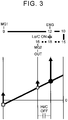
- FIG. 2 to FIG. 7 are collinear diagrams for illustrating the rotational speed of each of the rotary elements in the power split mechanism 6 and directions of the torque of the engine 3 and the motors 4, 5 in the travel modes.
- straight lines indicative of the rotary elements in the power split mechanism 6 are drawn in parallel with a space representing a gear ratio being interposed therebetween, and a distance from a base line that is orthogonal to these straight lines represents the rotational speed of the corresponding rotary element.
- the direction of the torque is indicated by an arrow on each of the straight lines indicative of the rotary elements, and a magnitude of the torque is indicated by the length of each of the arrows.
- the drive torque is output from the engine 3, the Hi clutch mechanism Hi/C is engaged, and the reaction torque is output from the first motor 4.
- the drive torque is output from the engine 3, the Lo clutch mechanism Lo/C is engaged, and the reaction torque is output from the first motor 4.
- the rotational speed of the first motor 4 in the HV-Hi mode or the HV-Lo mode is controlled to achieve the optimum efficiency of the entire power transmission apparatus 2 in consideration of fuel economy of the engine 3, drive efficiency of the first motor 4, and the like.
- the efficiency of the entire power transmission apparatus 2 is a value acquired by dividing a total amount of energy consumed by the engine 3 and the motors 4, 5 by an amount of drive energy acquired from a product of rotational speeds and the torque of the front wheels 1R, 1L.
- the rotational speed of the first motor 4 described above can be changed continuously, and the engine rotational speed is determined on the basis of the rotational speed of the first motor 4 and a vehicle speed.
- the power split mechanism 6 can function as a continuously variable transmission.
- each of the clutch mechanisms Lo/C, Hi/C is engaged, and thus the rotary elements in the power split mechanism 6 rotate at the same rotational speed. That is, the whole power of the engine 3 is output from the power split mechanism 6.
- a rotational speed ratio of the rotational speed of the ring gear 16 in the speed change section 8 to the rotational speed of the first motor 4 is lower in the EV-Lo mode than in the EV-Hi mode. That is, a reduction ratio is higher in the EV-Lo mode than in the EV-Hi mode. Accordingly, the high drive power can be acquired by setting the EV-Lo mode.
- Switching among the above-described travel modes is performed in accordance with the requested drive power and/or the vehicle speed.
- the rotational speed of the first motor 4 is controlled to set the direct-coupling mode, and then, the travel mode is switched from the direct-coupling mode to the HV-Hi mode or the HV-Lo mode.
- the rotational speed of the first motor 4 is controlled such that a difference between an input-side rotational speed and an output-side rotational speed of the clutch mechanism to be engaged becomes equal to or smaller than a permissible value. Then, the clutch mechanism is engaged.
- the travel mode can be switched by controlling the first motor 4 and each of the clutch mechanisms Lo/C, Hi/C in the similar manner.
- the magnitude of the torque applied to meshing surfaces of the clutch mechanism can be controlled by controlling the rotational speed and the torque of the first motor 4.
- the power transmission apparatus in the embodiment of the invention includes the plurality of meshing engagement mechanisms, and makes it possible to improve the mountability of the power transmission apparatus, more specifically, to reduce the axial length of the power transmission apparatus.
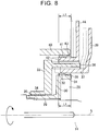
- FIG. 8 is a sectional view for illustrating the configuration of the power transmission apparatus in detail.
- an engaged member 28 is coupled to the input shaft 14.
- This engaged member 28 is configured to include a cylindrical first hub 29 whose inner peripheral surface is provided with spline teeth; an annular coupled section 30 that is coupled to one end (an end on the engine 3-side) of the first hub 29; and a first cylindrical section 31 that is integrated with an outer peripheral portion of a lateral surface at the engine 3-side of the coupled section 30.
- This first cylindrical section 31 corresponds to the "first rotational section” in the embodiment of the invention.
- On an outer peripheral surface of the first cylindrical section 31, a portion at the coupled section 30-side in the axial direction is provided with dog clutch teeth 32, each of which has a specified length in the axial direction of the first cylindrical section 31.
- the dog clutch teeth 32 correspond to the "first meshing teeth" in the embodiment of the invention.
- Spline teeth are formed on an outer peripheral surface of the input shaft 14, and the spline teeth thereof mesh with the spline teeth formed in the first hub 29.
- the engaged member 28 is rotated integrally with the input shaft 14.
- a step is formed in the input shaft 14 to position the first hub 29, and the first hub 29 is fitted to the input shaft 14 such that an end of the first hub 29 contacts the step.
- a nut or the like that positions an end at the engine 3-side of the first hub 29 may be provided.
- the carrier 18 in the speed change section 8 includes an annular first carrier plate (not shown) that is coupled to an end at the split section 7-side of a pinion shaft (not shown) that holds the pinion gear 17; and an annular second carrier plate 33 that is coupled to an end at the engine 3-side of the pinion shaft.
- a cylindrical second hub 34 is integrally formed in an inner peripheral portion of a lateral surface of the second carrier plate 33, the lateral surface facing toward a side opposite to the engine 3. The second hub 34 is fitted to the first hub 29 via a bush 35.
- a second cylindrical section 36 that extends toward the engine 3 beyond the first cylindrical section 31 is integrally formed in an outer peripheral portion of a lateral surface of the second carrier plate 33, the lateral surface facing toward the engine 3, more specifically, at a position radially outward of an outer diameter (an outer periphery) of the first cylindrical section 31.
- Spline teeth are formed on both of an inner peripheral surface and an outer peripheral surface of the second cylindrical section 36. That is, the second cylindrical section 36 is disposed concentrically with the first cylindrical section 31 and is formed to have a diameter larger than that of the first cylindrical section 31.
- the second cylindrical section 36 corresponds to the "second rotational section" and the "third rotational section" in the embodiment of the invention.
- a first movable member 37 having a cylindrical shape is inserted between the first cylindrical section 31 and the second cylindrical section 36. More specifically, spline teeth are formed on an outer peripheral surface of the first movable member 37, and the spline teeth thereof mesh with the spline teeth formed in the inner peripheral surface of the second cylindrical section 36. That is, the first movable member 37 and the second carrier plate 33 are constantly coupled to each other such that the first movable member 37 and the second carrier plate 33 are rotated integrally with each other (i.e., the first movable member 37 and the second carrier plate 33 are rotated together).
- dog clutch teeth 38 are formed on an inner peripheral surface of the first movable member 37 such that the dog clutch teeth 38 mesh with the dog clutch teeth 32 formed in the first cylindrical section 31 when the first movable member 37 moves toward the second carrier plate 33.
- the dog clutch teeth 38 correspond to the "third meshing teeth" in the embodiment of the invention.
- the dog clutch teeth 32 formed in the first cylindrical section 31 and the dog clutch teeth 38 formed in the first movable member 37 may have the same length, and the length is determined on the basis of maximum transmission torque determined in design and a permissible value of stress applied to meshing surfaces such that the stress applied to the meshing surfaces becomes equal to or lower than the permissible value when the dog clutch teeth 32, 38 mesh with each other to transmit the torque.
- a chamfer is formed on an end at the dog clutch teeth 38-side of each of the dog clutch teeth 32 and an end at the dog clutch teeth 32-side of each of the dog clutch teeth 38 such that the dog clutch teeth 32, 38 can mesh with each other even when phases of the dog clutch teeth 32, 38 in a rotational direction match each other.
- a first flange 39 is integrated with an end at the engine 3-side of the first movable member 37.
- This first flange 39 is provided to transmit an axial load to the first movable member 37.
- the configuration may be such that an annular slit is provided on an outer peripheral surface at the engine 3-side of the first movable member 37 and the first flange 39 is disposed in the slit such that the first flange 39 is rotatable relative to the first movable member 37.
- a member that presses the first movable member 37 may not have the annular shape unlike the first flange 39.
- a member such as a rod formed to extend in the radial direction may be disposed in the slit such that the member moves integrally with the first movable member 37 in the axial direction. That is, the first flange 39 may be integrated with the first movable member 37 in the axial direction of the first movable member 37.
- This first flange 39 corresponds to a "first pressing section" in the embodiment of the invention.
- a third cylindrical section 40 that extends toward the engine 3 is integrated with the ring gear 16 in the speed change section 8.
- This third cylindrical section 40 is formed to have an inner diameter larger than an outer diameter of the second carrier plate 33 and is disposed so as to surround the second carrier plate 33. More specifically, the third cylindrical section 40 is disposed concentrically with the second cylindrical section 36 and is formed to have a diameter larger than that of the second cylindrical section 36.
- This third cylindrical section 40 corresponds to the "fourth rotational section" in the embodiment of the invention. Further, an end at the engine 3-side of the third cylindrical section 40 is located at a position farther from the engine 3 than an end at the engine 3-side of the second cylindrical section 36 is.
- dog clutch teeth 41 are formed so as to at least partially overlap with the dog clutch teeth 32 formed in the first cylindrical section 31 in an axial direction of a rotation center axis L of each of the cylindrical sections 31, 36, 40.
- the dog clutch teeth 41 correspond to the "second meshing teeth" in the embodiment of the invention.
- the dog clutch teeth 32 formed in the first cylindrical section 31 may have a length in the axial direction (i.e., an axial length) that is different from the axial length of the dog clutch teeth 41 formed in the third cylindrical section 40.
- the dog clutch teeth 32 and the dog clutch teeth 41 may be formed such that the entire dog clutch teeth or the entire spline teeth (for example, the entire dog clutch teeth 32) that are short in the axial direction overlap with the dog clutch teeth (for example, the dog clutch teeth 41) that are long in the axial direction.
- a second movable member 42 having a cylindrical shape is inserted between the second cylindrical section 36 and the third cylindrical section 40. More specifically, spline teeth are formed on an inner peripheral surface of the second movable member 42, and the spline teeth thereof mesh with the spline teeth formed on the outer peripheral surface of the second cylindrical section 36. That is, the second movable member 42 and the second carrier plate 33 are always coupled to each other such that the second movable member 42 and the second carrier plate 33 are rotated integrally with each other (i.e., the second movable member 42 and the second carrier plate 33 are rotated together).
- dog clutch teeth 43 are formed on an outer peripheral surface of the second movable member 42 such that the dog clutch teeth 43 mesh with the dog clutch teeth 41 formed in the third cylindrical section 40 when the second movable member 42 moves toward the second carrier plate 33.
- the dog clutch teeth 43 correspond to the "fourth meshing teeth" in the embodiment of the invention.
- the dog clutch teeth 41 formed in the third cylindrical section 40 and the dog clutch teeth 43 formed in the second movable member 42 may have the same length, and this length is determined on the basis of the maximum transmission torque determined in the design and a permissible value of the stress applied to meshing surfaces such that the stress applied to the meshing surfaces becomes equal to or lower than the permissible value when the dog clutch teeth 41, 43 mesh with each other to transmit the torque.
- a chamfer is formed on an end at the dog clutch teeth 43-side of each of the dog clutch teeth 41 and an end at the dog clutch teeth 41-side of each of the dog clutch teeth 43 such that the dog clutch teeth 41, 43 can mesh with each other even when phases of the dog clutch teeth 41, 43 in the rotational direction match each other.
- a second flange 44 is integrated with an end at the engine 3-side of the second movable member 42.
- This second flange 44 is provided to transmit the axial load to the second movable member 42.
- an annular slit is provided on an outer peripheral surface at the engine 3-side of the second movable member 42 and the second flange 44 is disposed in the slit such that the second flange 44 is rotatable relative to the second movable member 42.
- a member that presses the second movable member 42 may not have the annular shape unlike the second flange 44.
- a member such as a rod formed to extend in the radial direction may be disposed in the slit such that the member moves integrally with the second movable member 42 in the axial direction. That is, the second flange 44 may be integrated with the second movable member 42 in the axial direction of the second movable member 42.
- This second flange 44 corresponds to a "second pressing section" in the embodiment of the invention.
- the configuration shown in FIG. 8 is assembled in the following order. More specifically, initially, the engaged member 28 is engaged with and fixed to the input shaft 14. Thereafter, the bush 35 is fitted to the first hub 29 from a left side (the side opposite to the engine 3) in FIG. 8 , and a unit of the speed change section 8 is assembled to the bush 35. More specifically, the second carrier plate 33 is fitted to the bush 35. Thereafter, the second movable member 42 is assembled from the engine 3-side in the axial direction such that the spline teeth formed in the second movable member 42 and the spline teeth formed on the outer peripheral surface of the second cylindrical section 36 mesh with each other. At the time, the dog clutch teeth 41 and the dog clutch teeth 43 do not need to mesh with each other.
- the first movable member 37 is assembled from the engine 3-side in the axial direction such that the spline teeth formed in the first movable member 37 and the spline teeth formed on the inner peripheral surface of the second cylindrical section 36 mesh with each other.
- the dog clutch teeth 32 and the dog clutch teeth 38 do not need to mesh with each other.
- the dog clutch teeth 32, 38 are caused to mesh with each other by increasing a fitting amount of the first movable member 37 and the first cylindrical section 31 (i.e., a fitting amount by which the first movable member 37 and the first cylindrical section 31 are fitted to each other), or in the case where the dog clutch teeth 41, 43 are caused to mesh with each other by increasing a fitting amount of the second movable member 42 and the third cylindrical section 40 (i.e., a fitting amount by which the second movable member 42 and the third cylindrical section 40 are fitted to each other), there is no need to, for example, match phases of the movable members 37, 42 at the time of assembly thereof.
- the assemblability can be improved, that is, the movable members 37, 42 can be fitted more easily.
- a semicircular first shift fork 45 is engaged with an outer peripheral surface of the first flange 39.
- the first shift fork 45 shown in FIG. 9 is formed to have a plate thickness larger than that of the first flange 39, and a groove 46 is formed on an inner peripheral surface of the first shift fork 45.
- the first flange 39 can slide in the groove 46 in a rotational direction and is locked in the axial direction in the groove 46.
- An outer periphery of the first flange 39 is disposed in the groove 46. Accordingly, when the first shift fork 45 is pressed in the axial direction, a load thereof is transmitted to the first flange 39.
- FIG. 9 a semicircular first shift fork 45 is engaged with an outer peripheral surface of the first flange 39.
- a plurality of lugs 47 is formed on the inner peripheral surface of the first shift fork 45 to prevent detachment of the first flange 39 from the groove 46.
- a lubricant may be supplied to sliding sections of the first shift fork 45 and the first flange 39 or may cover the sliding sections of the first shift fork 45 and the first flange 39 with a member having a small friction coefficient.
- One end of a rod 48 is coupled to a lateral surface at one side of a central portion of the first shift fork 45 in a circumferential direction, via a spring (not shown), the one side being opposite to the engine 3.
- the rod 48 is provided so as to extend through a case (not shown) that accommodates the power transmission apparatus 2, and an electromagnetic actuator 49 that presses the first shift fork 45 is coupled to the other end of the rod 48 that extends to the outside of the case.
- the electromagnetic actuator 49 shown in FIG. 9 is configured to include a motor and a cam mechanism that converts torque of the motor to a load of the rod 48 in the axial direction (i.e., an axial load of the rod 48).
- the ends of the dog clutch teeth 32 and the ends of the dog clutch teeth 38 come in contact with each other when the rod 48 presses the first flange 39, a reaction force applied to the first flange 39 is increased.
- the above-described spring is provided to prevent a situation where an excessive bending load is applied to the first flange 39 in such a case.
- the rigidity of the first flange 39 can be reduced, that is, the plate thickness of the first flange 39 can be reduced. Accordingly, the axial length of the power transmission apparatus 2 can be further reduced.
- the electromagnetic actuator 49 when the first shift fork 45 is pulled in a left direction in FIG. 8 by the electromagnetic actuator 49, the load of the first shift fork 45 is transmitted to the first movable member 37 via the first flange 39. As a result, the dog clutch teeth 32 formed in the first cylindrical section 31 and the dog clutch teeth 38 formed in the first movable member 37 mesh with each other.
- the first shift fork 45 is pressed by the electromagnetic actuator 49, the load of the first shift fork 45 is transmitted to the first movable member 37 via the first flange 39.
- the dog clutch teeth 32 formed in the first cylindrical section 31 and the dog clutch teeth 38 formed in the first movable member 37 are disengaged from each other. That is, the electromagnetic actuator 49, the first shift fork 45, the first flange 39, and the first movable member 37 constitute the meshing engagement mechanism (the Lo clutch mechanism Lo/C).
- the Hi clutch mechanism Hi/C is configured similarly to the Lo clutch mechanism Lo/C. That is, a second shift fork 50 that is configured similarly to the first shift fork 45 is coupled to the second flange 44, and a rod 51 and a second electromagnetic actuator 52 that apply the axial load to the second shift fork 50 are provided. Note that, in the example shown in FIG. 9 , the first shift fork 45 and the second shift fork 50 are disposed such that phases of the first shift fork 45 and the second shift fork 50 are offset from each other in the rotational direction.
- the phases of the first shift fork 45 and the second shift fork 50 are offset from each other in the rotational direction in order to prevent interference between a portion of the first shift fork 45, to which the rod 48 is coupled, and a portion of the second shift fork 50, to which the rod 51 is coupled.
- the above-described Lo clutch mechanism Lo/C is configured such that the first movable member 37 is located at a position indicated by solid lines in FIG. 8 in the state where the dog clutch teeth 32, 38 are disengaged from each other, that is, in the disengaged state.
- the Lo clutch mechanism Lo/C is configured such that the first movable member 37 is located at a position indicated by broken lines in FIG. 8 in the state where the dog clutch teeth 32, 38 mesh with each other (i.e., the dog clutch teeth 32, 38 are engaged with each other), that is, in the engaged state.
- a movable region, in the axial direction, of the dog clutch teeth 38 formed in the first movable member 37 is a range indicated by "L1" in FIG. 8 .
- This movable region corresponds to a "first movable region” in the embodiment of the invention.
- the Hi clutch mechanism Hi/C is configured such that the second movable member 42 is located at a position indicated by solid lines in FIG. 8 in the state where the dog clutch teeth 41, 43 are disengaged from each other, that is, in the disengaged state.
- the Hi clutch mechanism Hi/C is configured such that the second movable member 42 is located at a position indicated by broken lines in FIG. 8 in the state where the dog clutch teeth 41, 43 mesh with each other (i.e., the dog clutch teeth 41, 43 are engaged with each other), that is, in the engaged state.
- a movable region, in the axial direction, of the dog clutch teeth 43 formed in the second movable member 42 is a range indicated by "L2" in FIG. 8 .
- This movable region corresponds to a "second movable region" in the embodiment of the invention.
- the movable region L1 of the dog clutch teeth 38 formed in the first movable member 37 matches the movable region L2 of the dog clutch teeth 43 formed in the second movable member 42.
- the movable region L1 and the movable region L2 overlap with each other in a radial direction with respect to a rotational axis L. Accordingly, there is no need to secure ranges in the axial direction for the movable regions L1, L2. In other words, it is possible to prevent a situation where the movable regions L1, L2 are arranged in the axial direction. As a result, even in the case where the two meshing engagement mechanisms are provided in the power transmission apparatus, an increase in the axial length of the power transmission apparatus can be prevented.
- the movable regions L1, L2 do not necessarily need to completely match each other, and at least a portion of the movable region L1 and at least a portion of the movable region L2 may overlap with each other in the radial direction with respect to the rotational axis L.
- the axial length of the dog clutch teeth 32, 38 and the axial length of the dog clutch teeth 41, 43 differ from each other, distances through which the movable members 37, 42 move also differ from each other in accordance with the difference between the axial length of the dog clutch teeth 32, 38 and the axial length of the dog clutch teeth 41, 43.
- the entire movable region L2 of the movable member that is movable in a short movable region may overlap with the movable region L1 of the movable member that is movable in a long movable region (for example, the first movable member 37), in the radial direction with respect to the rotational axis L.
- the flanges 39, 44 are respectively coupled to the first movable member 37 and the second movable member 42 and the outer peripheral portions of the flanges 39, 44 respectively receive the loads from the actuators 49, 52.
- the position where the dog clutch teeth mesh with each other and the position where a thrust for causing the dog clutch teeth to mesh each other is generated are made different from each other in the radial direction. As a result, the increase in the axial length of the power transmission apparatus 2 can be prevented.
- arrangement positions of the actuators 49, 52 i.e., the positions at which the actuators 49, 52 are arranged
- the first movable member 37 and the second cylindrical section 36 are coupled to each other such that the first movable member 37 and the second cylindrical section 36 are rotated integrally with each other.
- relative rotation of the first flange 39 and the second cylindrical section 36 can be prevented.
- a fitting amount of the first movable member 37 and the second cylindrical section 36 i.e., a fitting amount by which the first movable member 37 and the second cylindrical section 36 are fitted to each other
- the power loss can be reduced. Accordingly, there is no need to provide a clearance between the first flange 39 and the end of the second cylindrical section 36 when the dog clutch teeth 32, 38 mesh with each other. Thus, a region where the first flange 39 moves can be set on the side of the second cylindrical section 36. For this reason, there is no need to secure the excessively large region where the first flange 39 moves, and thus the axial length of the power transmission apparatus 2 can be reduced.
- the end of the second cylindrical section 36 has a function of positioning the first flange 39. Accordingly, there is no need to provide another positioning mechanism or the like. Thus, the axial length of the power transmission apparatus 2 can be reduced.
- the Lo clutch mechanism Lo/C is engaged, and the Hi clutch mechanism Hi/C is disengaged.
- the second flange 44 is located on the engine 3-side in the axial direction, and the first flange 39 is located on the side opposite to the engine 3 in the axial direction. That is, the flanges 39, 44 approach each other. Meanwhile, in the configuration shown in FIG. 8 , the second flange 44 is located on the engine 3-side in the axial direction, and the first flange 39 is located on the side opposite to the engine 3 in the axial direction. That is, the flanges 39, 44 approach each other. Meanwhile, in the configuration shown in FIG.
- first meshing engagement mechanism and the second meshing engagement mechanism in the embodiment of the invention may be configured to engage the different rotational sections with each other. More specifically, the first meshing engagement mechanism may be configured to engage the first rotational section with the second rotational section that rotates relative to the first rotational section, and the second meshing engagement mechanism may be configured to engage the third rotational section that rotates relative to the first rotational section and the second rotational section, with the fourth rotational section that rotates relative to the first rotational section, the second rotational section, and the third rotational section.
- the cylindrical rotational section which is disposed on the side of the outer periphery of the second movable member and has the end facing the second flange, constantly meshes with the second movable member.
- the configuration of the Lo clutch mechanism Lo/C is not limited to a configuration in which the dog clutch teeth 32, 38 mesh with each other when the first movable member 37 moves to increase the fitting amount of the first movable member 37 and the second cylindrical section 36.
- the Lo clutch mechanism Lo/C may be configured such that the dog clutch teeth 32, 38 are disengaged from each other when the first movable member 37 moves to increase the fitting amount of the first movable member 37 and the second cylindrical section 36, and the dog clutch teeth 32, 38 mesh with each other when the first movable member 37 moves to reduce the fitting amount of the first movable member 37 and the second cylindrical section 36.
- the configuration of the Hi clutch mechanism Hi/C is not limited to a configuration in which the dog clutch teeth 41, 43 mesh with each other when the second movable member 42 moves to increase the fitting amount of the second movable member 42 and the third cylindrical section 40.
- the Hi clutch mechanism Hi/C may be configured such that the dog clutch teeth 41, 43 are disengaged from each other when the second movable member 42 moves to increase the fitting amount of the second movable member 42 and the third cylindrical section 40, and that the dog clutch teeth 41, 43 mesh with each other when the second movable member 42 moves to reduce the fitting amount of the second movable member 42 and the third cylindrical section 40.
- the actuators configured to control the clutch mechanisms Lo/C, Hi/C are not limited to the electromagnetic actuators, and may be hydraulic actuators.
- each of the actuators does not necessarily need to be attached to the outside of the case, and may be attached to an inner surface of the case.
Landscapes
- Engineering & Computer Science (AREA)
- General Engineering & Computer Science (AREA)
- Mechanical Engineering (AREA)
- Chemical & Material Sciences (AREA)
- Combustion & Propulsion (AREA)
- Transportation (AREA)
- Mechanical Operated Clutches (AREA)
- Hybrid Electric Vehicles (AREA)
- Structure Of Transmissions (AREA)
Applications Claiming Priority (1)
| Application Number | Priority Date | Filing Date | Title |
|---|---|---|---|
| JP2018015367A JP6911782B2 (ja) | 2018-01-31 | 2018-01-31 | 動力伝達装置 |
Publications (1)
| Publication Number | Publication Date |
|---|---|
| EP3521084A1 true EP3521084A1 (de) | 2019-08-07 |
Family
ID=65276004
Family Applications (1)
| Application Number | Title | Priority Date | Filing Date |
|---|---|---|---|
| EP19154778.5A Ceased EP3521084A1 (de) | 2018-01-31 | 2019-01-31 | Leistungsübertragungsvorrichtung |
Country Status (7)
| Country | Link |
|---|---|
| US (1) | US10704617B2 (de) |
| EP (1) | EP3521084A1 (de) |
| JP (1) | JP6911782B2 (de) |
| KR (1) | KR102173857B1 (de) |
| CN (1) | CN110091702B (de) |
| BR (1) | BR102019001027A2 (de) |
| RU (1) | RU2699515C1 (de) |
Cited By (3)
| Publication number | Priority date | Publication date | Assignee | Title |
|---|---|---|---|---|
| WO2021083449A1 (de) | 2019-10-29 | 2021-05-06 | Schaeffler Technologies AG & Co. KG | Schalteinrichtung für ein hybrides antriebssystem eines kraftfahrzeuges; antriebssystem sowie kraftfahrzeug |
| DE102021111852A1 (de) | 2021-05-06 | 2022-11-10 | Schaeffler Technologies AG & Co. KG | EVT-Getriebe mit Erweiterung um seriellen Modus und Fahrzeugantriebsstrang |
| DE102021111921A1 (de) | 2021-05-07 | 2022-11-10 | Schaeffler Technologies AG & Co. KG | Fahrzeugantriebsstrang mit reduziertem koppelsatzaufweisenden (EVT-) Getriebe |
Families Citing this family (6)
| Publication number | Priority date | Publication date | Assignee | Title |
|---|---|---|---|---|
| JP6617745B2 (ja) * | 2017-04-28 | 2019-12-11 | トヨタ自動車株式会社 | ハイブリッド車両の駆動装置 |
| WO2021065798A1 (ja) * | 2019-09-30 | 2021-04-08 | アイシン・エィ・ダブリュ株式会社 | 車両用駆動伝達装置 |
| DE102019131770A1 (de) * | 2019-11-25 | 2020-11-19 | Schaeffler Technologies AG & Co. KG | Antriebsvorrichtung mit achsparallelem 2-Gang-Getriebe |
| JP7218732B2 (ja) * | 2020-01-22 | 2023-02-07 | トヨタ自動車株式会社 | 動力伝達装置 |
| JP2022181302A (ja) | 2021-05-26 | 2022-12-08 | トヨタ自動車株式会社 | 動力伝達装置及びその製造方法 |
| JP7476873B2 (ja) * | 2021-11-30 | 2024-05-01 | トヨタ自動車株式会社 | 動力伝達装置 |
Citations (5)
| Publication number | Priority date | Publication date | Assignee | Title |
|---|---|---|---|---|
| US20080132374A1 (en) * | 2006-12-01 | 2008-06-05 | Dumitru Puiu | Hybrid transmission having synchronizers |
| DE102011007454A1 (de) * | 2011-04-15 | 2012-10-18 | Schaeffler Technologies AG & Co. KG | Antriebsvorrichtung für ein Kraftfahrzeug |
| WO2013076828A1 (ja) | 2011-11-22 | 2013-05-30 | トヨタ自動車株式会社 | 車両用自動変速機 |
| DE102014208794A1 (de) * | 2014-05-09 | 2015-11-12 | Zf Friedrichshafen Ag | Vorrichtung zum Schalten eines ersten und zweiten Schaltelements, und Getriebe mit einer solchen Vorrichtung |
| EP3106338A1 (de) * | 2015-06-18 | 2016-12-21 | Toyota Jidosha Kabushiki Kaisha | Antriebseinheit für ein hybridfahrzeug |
Family Cites Families (15)
| Publication number | Priority date | Publication date | Assignee | Title |
|---|---|---|---|---|
| DD139154B1 (de) * | 1978-10-04 | 1981-02-25 | Walter Arpert | Doppeltwirkender freilauf |
| JPS6447622A (en) * | 1987-08-19 | 1989-02-22 | Honda Motor Co Ltd | Dog clutch device |
| YU47761B (sr) * | 1988-03-11 | 1996-01-09 | Zahnradfabrik Friedrichshafen Ag. | Pogonski uređaj sa jednim dvostepenim prenosnikom |
| JP3571858B2 (ja) * | 1996-07-16 | 2004-09-29 | ジヤトコ株式会社 | 自動変速機用歯車変速装置 |
| JP3982972B2 (ja) * | 1999-04-05 | 2007-09-26 | トヨタ自動車株式会社 | 四輪駆動車の動力伝達装置 |
| JP2004019830A (ja) * | 2002-06-18 | 2004-01-22 | Toyota Motor Corp | 動力伝達断続装置 |
| EP1857701B1 (de) * | 2004-06-29 | 2008-07-16 | BorgWarner Inc. | Mehrfachkupplungsanordnung |
| DE102005005693A1 (de) * | 2005-02-08 | 2006-08-17 | Fzgmbh | Schaltvorrichtung |
| JP4165600B2 (ja) * | 2006-11-22 | 2008-10-15 | トヨタ自動車株式会社 | 連結装置、それを備えた動力出力装置およびハイブリッド自動車 |
| EP2650560B1 (de) * | 2010-11-19 | 2020-10-21 | Ikeya Formula Co., Ltd. | Getriebe und schaltsteuerungssystem |
| DE102014205185A1 (de) * | 2013-03-28 | 2014-10-02 | Ford Global Technologies, Llc | Mehrstufiges Getriebe |
| DE102013221130A1 (de) * | 2013-10-17 | 2015-04-23 | Zf Friedrichshafen Ag | Vorrichtung zum lösbaren Verbinden von zwei Bauteilen mit wenigstens einer Welle |
| JP6696179B2 (ja) * | 2016-01-13 | 2020-05-20 | 株式会社ジェイテクト | 差動装置 |
| JP6460044B2 (ja) * | 2016-04-28 | 2019-01-30 | トヨタ自動車株式会社 | 駆動装置 |
| US10364872B2 (en) * | 2017-10-17 | 2019-07-30 | Arvinmeritor Technology, Llc | Axle assembly having a gear reduction unit and an interaxle differential unit |
-
2018
- 2018-01-31 JP JP2018015367A patent/JP6911782B2/ja active Active
-
2019
- 2019-01-18 BR BR102019001027-4A patent/BR102019001027A2/pt not_active Application Discontinuation
- 2019-01-22 KR KR1020190008143A patent/KR102173857B1/ko active IP Right Grant
- 2019-01-22 RU RU2019101631A patent/RU2699515C1/ru active
- 2019-01-22 US US16/253,696 patent/US10704617B2/en active Active
- 2019-01-31 EP EP19154778.5A patent/EP3521084A1/de not_active Ceased
- 2019-01-31 CN CN201910098427.2A patent/CN110091702B/zh not_active Expired - Fee Related
Patent Citations (5)
| Publication number | Priority date | Publication date | Assignee | Title |
|---|---|---|---|---|
| US20080132374A1 (en) * | 2006-12-01 | 2008-06-05 | Dumitru Puiu | Hybrid transmission having synchronizers |
| DE102011007454A1 (de) * | 2011-04-15 | 2012-10-18 | Schaeffler Technologies AG & Co. KG | Antriebsvorrichtung für ein Kraftfahrzeug |
| WO2013076828A1 (ja) | 2011-11-22 | 2013-05-30 | トヨタ自動車株式会社 | 車両用自動変速機 |
| DE102014208794A1 (de) * | 2014-05-09 | 2015-11-12 | Zf Friedrichshafen Ag | Vorrichtung zum Schalten eines ersten und zweiten Schaltelements, und Getriebe mit einer solchen Vorrichtung |
| EP3106338A1 (de) * | 2015-06-18 | 2016-12-21 | Toyota Jidosha Kabushiki Kaisha | Antriebseinheit für ein hybridfahrzeug |
Cited By (5)
| Publication number | Priority date | Publication date | Assignee | Title |
|---|---|---|---|---|
| WO2021083449A1 (de) | 2019-10-29 | 2021-05-06 | Schaeffler Technologies AG & Co. KG | Schalteinrichtung für ein hybrides antriebssystem eines kraftfahrzeuges; antriebssystem sowie kraftfahrzeug |
| DE102021111852A1 (de) | 2021-05-06 | 2022-11-10 | Schaeffler Technologies AG & Co. KG | EVT-Getriebe mit Erweiterung um seriellen Modus und Fahrzeugantriebsstrang |
| WO2022233355A1 (de) | 2021-05-06 | 2022-11-10 | Schaeffler Technologies AG & Co. KG | Fahrzeugantriebsstrang |
| DE102021111921A1 (de) | 2021-05-07 | 2022-11-10 | Schaeffler Technologies AG & Co. KG | Fahrzeugantriebsstrang mit reduziertem koppelsatzaufweisenden (EVT-) Getriebe |
| DE102021111921B4 (de) | 2021-05-07 | 2023-04-27 | Schaeffler Technologies AG & Co. KG | Fahrzeugantriebsstrang mit reduziertem koppelsatzaufweisenden (EVT-) Getriebe |
Also Published As
| Publication number | Publication date |
|---|---|
| CN110091702B (zh) | 2022-06-24 |
| JP2019132350A (ja) | 2019-08-08 |
| RU2699515C1 (ru) | 2019-09-05 |
| US20190234471A1 (en) | 2019-08-01 |
| CN110091702A (zh) | 2019-08-06 |
| JP6911782B2 (ja) | 2021-07-28 |
| KR102173857B1 (ko) | 2020-11-04 |
| KR20190093126A (ko) | 2019-08-08 |
| US10704617B2 (en) | 2020-07-07 |
| BR102019001027A2 (pt) | 2019-09-17 |
Similar Documents
| Publication | Publication Date | Title |
|---|---|---|
| US10704617B2 (en) | Power transmission apparatus | |
| JP5842998B2 (ja) | 車両用変速機 | |
| US10286771B2 (en) | Drive unit for hybrid vehicle | |
| US7255186B2 (en) | Hybrid drive system and vehicle equipped therewith | |
| US8388478B2 (en) | Input shaft for hybrid transmission | |
| US10197134B2 (en) | Hybrid transmission having electro-magnetically actuated pawl clutch | |
| US9586468B2 (en) | Hybrid drive device | |
| US9630487B2 (en) | Hybrid system | |
| US20160265630A1 (en) | Power transmission device | |
| US10024370B1 (en) | Hybrid transmission having electro-magnetically actuated pawl clutch | |
| US20160159212A1 (en) | Drive system for hybrid vehicle | |
| US11242914B2 (en) | Power transmission unit | |
| US10024429B2 (en) | Automatic transmission | |
| US10308107B2 (en) | Multi-mode hybrid powertrain | |
| JP2014024360A (ja) | アクチュエータユニット | |
| JP6380682B2 (ja) | 車両用駆動装置 | |
| JP2020101224A (ja) | 動力伝達装置 | |
| JP2022152833A (ja) | 車両用駆動装置 |
Legal Events
| Date | Code | Title | Description |
|---|---|---|---|
| PUAI | Public reference made under article 153(3) epc to a published international application that has entered the european phase |
Free format text: ORIGINAL CODE: 0009012 |
|
| STAA | Information on the status of an ep patent application or granted ep patent |
Free format text: STATUS: REQUEST FOR EXAMINATION WAS MADE |
|
| 17P | Request for examination filed |
Effective date: 20190131 |
|
| AK | Designated contracting states |
Kind code of ref document: A1 Designated state(s): AL AT BE BG CH CY CZ DE DK EE ES FI FR GB GR HR HU IE IS IT LI LT LU LV MC MK MT NL NO PL PT RO RS SE SI SK SM TR |
|
| AX | Request for extension of the european patent |
Extension state: BA ME |
|
| STAA | Information on the status of an ep patent application or granted ep patent |
Free format text: STATUS: EXAMINATION IS IN PROGRESS |
|
| 17Q | First examination report despatched |
Effective date: 20211102 |
|
| STAA | Information on the status of an ep patent application or granted ep patent |
Free format text: STATUS: THE APPLICATION HAS BEEN REFUSED |
|
| 18R | Application refused |
Effective date: 20221024 |