EP3520887A1 - Vorrichtung zum aufeinanderfolgenden einbringen von additiven in ein polymergranulat und verwendung der vorrichtung - Google Patents
Vorrichtung zum aufeinanderfolgenden einbringen von additiven in ein polymergranulat und verwendung der vorrichtung Download PDFInfo
- Publication number
- EP3520887A1 EP3520887A1 EP18155132.6A EP18155132A EP3520887A1 EP 3520887 A1 EP3520887 A1 EP 3520887A1 EP 18155132 A EP18155132 A EP 18155132A EP 3520887 A1 EP3520887 A1 EP 3520887A1
- Authority
- EP
- European Patent Office
- Prior art keywords
- additive
- mixer
- mixing
- polymer
- polymer granules
- Prior art date
- Legal status (The legal status is an assumption and is not a legal conclusion. Google has not performed a legal analysis and makes no representation as to the accuracy of the status listed.)
- Granted
Links
Images




Classifications
-
- B—PERFORMING OPERATIONS; TRANSPORTING
- B01—PHYSICAL OR CHEMICAL PROCESSES OR APPARATUS IN GENERAL
- B01F—MIXING, e.g. DISSOLVING, EMULSIFYING OR DISPERSING
- B01F35/00—Accessories for mixers; Auxiliary operations or auxiliary devices; Parts or details of general application
- B01F35/56—General build-up of the mixers
- B01F35/561—General build-up of the mixers the mixer being built-up from a plurality of modules or stacked plates comprising complete or partial elements of the mixer
-
- B—PERFORMING OPERATIONS; TRANSPORTING
- B29—WORKING OF PLASTICS; WORKING OF SUBSTANCES IN A PLASTIC STATE IN GENERAL
- B29B—PREPARATION OR PRETREATMENT OF THE MATERIAL TO BE SHAPED; MAKING GRANULES OR PREFORMS; RECOVERY OF PLASTICS OR OTHER CONSTITUENTS OF WASTE MATERIAL CONTAINING PLASTICS
- B29B7/00—Mixing; Kneading
- B29B7/30—Mixing; Kneading continuous, with mechanical mixing or kneading devices
- B29B7/34—Mixing; Kneading continuous, with mechanical mixing or kneading devices with movable mixing or kneading devices
- B29B7/38—Mixing; Kneading continuous, with mechanical mixing or kneading devices with movable mixing or kneading devices rotary
- B29B7/40—Mixing; Kneading continuous, with mechanical mixing or kneading devices with movable mixing or kneading devices rotary with single shaft
- B29B7/42—Mixing; Kneading continuous, with mechanical mixing or kneading devices with movable mixing or kneading devices rotary with single shaft with screw or helix
- B29B7/421—Mixing; Kneading continuous, with mechanical mixing or kneading devices with movable mixing or kneading devices rotary with single shaft with screw or helix with screw and additionally other mixing elements on the same shaft, e.g. paddles, discs, bearings, rotor blades of the Banbury type
-
- B—PERFORMING OPERATIONS; TRANSPORTING
- B01—PHYSICAL OR CHEMICAL PROCESSES OR APPARATUS IN GENERAL
- B01F—MIXING, e.g. DISSOLVING, EMULSIFYING OR DISPERSING
- B01F23/00—Mixing according to the phases to be mixed, e.g. dispersing or emulsifying
- B01F23/60—Mixing solids with solids
-
- B—PERFORMING OPERATIONS; TRANSPORTING
- B01—PHYSICAL OR CHEMICAL PROCESSES OR APPARATUS IN GENERAL
- B01F—MIXING, e.g. DISSOLVING, EMULSIFYING OR DISPERSING
- B01F23/00—Mixing according to the phases to be mixed, e.g. dispersing or emulsifying
- B01F23/60—Mixing solids with solids
- B01F23/64—Mixing solids with solids using rotatable mixing elements at the lower end of discharge hoppers
-
- B—PERFORMING OPERATIONS; TRANSPORTING
- B01—PHYSICAL OR CHEMICAL PROCESSES OR APPARATUS IN GENERAL
- B01F—MIXING, e.g. DISSOLVING, EMULSIFYING OR DISPERSING
- B01F27/00—Mixers with rotary stirring devices in fixed receptacles; Kneaders
- B01F27/05—Stirrers
- B01F27/11—Stirrers characterised by the configuration of the stirrers
- B01F27/114—Helically shaped stirrers, i.e. stirrers comprising a helically shaped band or helically shaped band sections
- B01F27/1144—Helically shaped stirrers, i.e. stirrers comprising a helically shaped band or helically shaped band sections with a plurality of blades following a helical path on a shaft or a blade support
-
- B—PERFORMING OPERATIONS; TRANSPORTING
- B01—PHYSICAL OR CHEMICAL PROCESSES OR APPARATUS IN GENERAL
- B01F—MIXING, e.g. DISSOLVING, EMULSIFYING OR DISPERSING
- B01F27/00—Mixers with rotary stirring devices in fixed receptacles; Kneaders
- B01F27/05—Stirrers
- B01F27/11—Stirrers characterised by the configuration of the stirrers
- B01F27/19—Stirrers with two or more mixing elements mounted in sequence on the same axis
- B01F27/192—Stirrers with two or more mixing elements mounted in sequence on the same axis with dissimilar elements
- B01F27/1921—Stirrers with two or more mixing elements mounted in sequence on the same axis with dissimilar elements comprising helical elements and paddles
-
- B—PERFORMING OPERATIONS; TRANSPORTING
- B01—PHYSICAL OR CHEMICAL PROCESSES OR APPARATUS IN GENERAL
- B01F—MIXING, e.g. DISSOLVING, EMULSIFYING OR DISPERSING
- B01F27/00—Mixers with rotary stirring devices in fixed receptacles; Kneaders
- B01F27/60—Mixers with rotary stirring devices in fixed receptacles; Kneaders with stirrers rotating about a horizontal or inclined axis
- B01F27/72—Mixers with rotary stirring devices in fixed receptacles; Kneaders with stirrers rotating about a horizontal or inclined axis with helices or sections of helices
-
- B—PERFORMING OPERATIONS; TRANSPORTING
- B01—PHYSICAL OR CHEMICAL PROCESSES OR APPARATUS IN GENERAL
- B01F—MIXING, e.g. DISSOLVING, EMULSIFYING OR DISPERSING
- B01F27/00—Mixers with rotary stirring devices in fixed receptacles; Kneaders
- B01F27/60—Mixers with rotary stirring devices in fixed receptacles; Kneaders with stirrers rotating about a horizontal or inclined axis
- B01F27/72—Mixers with rotary stirring devices in fixed receptacles; Kneaders with stirrers rotating about a horizontal or inclined axis with helices or sections of helices
- B01F27/721—Mixers with rotary stirring devices in fixed receptacles; Kneaders with stirrers rotating about a horizontal or inclined axis with helices or sections of helices with two or more helices in the same receptacle
- B01F27/723—Mixers with rotary stirring devices in fixed receptacles; Kneaders with stirrers rotating about a horizontal or inclined axis with helices or sections of helices with two or more helices in the same receptacle the helices intermeshing to knead the mixture
-
- B—PERFORMING OPERATIONS; TRANSPORTING
- B01—PHYSICAL OR CHEMICAL PROCESSES OR APPARATUS IN GENERAL
- B01F—MIXING, e.g. DISSOLVING, EMULSIFYING OR DISPERSING
- B01F35/00—Accessories for mixers; Auxiliary operations or auxiliary devices; Parts or details of general application
- B01F35/181—Preventing generation of dust or dirt; Sieves; Filters
- B01F35/189—Venting, degassing or ventilating of gases, fumes or toxic vapours during mixing
-
- B—PERFORMING OPERATIONS; TRANSPORTING
- B01—PHYSICAL OR CHEMICAL PROCESSES OR APPARATUS IN GENERAL
- B01F—MIXING, e.g. DISSOLVING, EMULSIFYING OR DISPERSING
- B01F35/00—Accessories for mixers; Auxiliary operations or auxiliary devices; Parts or details of general application
- B01F35/71—Feed mechanisms
- B01F35/715—Feeding the components in several steps, e.g. successive steps
-
- B—PERFORMING OPERATIONS; TRANSPORTING
- B01—PHYSICAL OR CHEMICAL PROCESSES OR APPARATUS IN GENERAL
- B01F—MIXING, e.g. DISSOLVING, EMULSIFYING OR DISPERSING
- B01F35/00—Accessories for mixers; Auxiliary operations or auxiliary devices; Parts or details of general application
- B01F35/75—Discharge mechanisms
- B01F35/754—Discharge mechanisms characterised by the means for discharging the components from the mixer
- B01F35/7545—Discharge mechanisms characterised by the means for discharging the components from the mixer using slides
-
- B—PERFORMING OPERATIONS; TRANSPORTING
- B29—WORKING OF PLASTICS; WORKING OF SUBSTANCES IN A PLASTIC STATE IN GENERAL
- B29B—PREPARATION OR PRETREATMENT OF THE MATERIAL TO BE SHAPED; MAKING GRANULES OR PREFORMS; RECOVERY OF PLASTICS OR OTHER CONSTITUENTS OF WASTE MATERIAL CONTAINING PLASTICS
- B29B7/00—Mixing; Kneading
- B29B7/30—Mixing; Kneading continuous, with mechanical mixing or kneading devices
- B29B7/34—Mixing; Kneading continuous, with mechanical mixing or kneading devices with movable mixing or kneading devices
- B29B7/38—Mixing; Kneading continuous, with mechanical mixing or kneading devices with movable mixing or kneading devices rotary
- B29B7/46—Mixing; Kneading continuous, with mechanical mixing or kneading devices with movable mixing or kneading devices rotary with more than one shaft
- B29B7/48—Mixing; Kneading continuous, with mechanical mixing or kneading devices with movable mixing or kneading devices rotary with more than one shaft with intermeshing devices, e.g. screws
- B29B7/482—Mixing; Kneading continuous, with mechanical mixing or kneading devices with movable mixing or kneading devices rotary with more than one shaft with intermeshing devices, e.g. screws provided with screw parts in addition to other mixing parts, e.g. paddles, gears, discs
-
- B—PERFORMING OPERATIONS; TRANSPORTING
- B29—WORKING OF PLASTICS; WORKING OF SUBSTANCES IN A PLASTIC STATE IN GENERAL
- B29B—PREPARATION OR PRETREATMENT OF THE MATERIAL TO BE SHAPED; MAKING GRANULES OR PREFORMS; RECOVERY OF PLASTICS OR OTHER CONSTITUENTS OF WASTE MATERIAL CONTAINING PLASTICS
- B29B7/00—Mixing; Kneading
- B29B7/80—Component parts, details or accessories; Auxiliary operations
- B29B7/88—Adding charges, i.e. additives
- B29B7/90—Fillers or reinforcements, e.g. fibres
-
- B—PERFORMING OPERATIONS; TRANSPORTING
- B29—WORKING OF PLASTICS; WORKING OF SUBSTANCES IN A PLASTIC STATE IN GENERAL
- B29B—PREPARATION OR PRETREATMENT OF THE MATERIAL TO BE SHAPED; MAKING GRANULES OR PREFORMS; RECOVERY OF PLASTICS OR OTHER CONSTITUENTS OF WASTE MATERIAL CONTAINING PLASTICS
- B29B7/00—Mixing; Kneading
- B29B7/30—Mixing; Kneading continuous, with mechanical mixing or kneading devices
- B29B7/58—Component parts, details or accessories; Auxiliary operations
- B29B7/60—Component parts, details or accessories; Auxiliary operations for feeding, e.g. end guides for the incoming material
-
- C—CHEMISTRY; METALLURGY
- C08—ORGANIC MACROMOLECULAR COMPOUNDS; THEIR PREPARATION OR CHEMICAL WORKING-UP; COMPOSITIONS BASED THEREON
- C08J—WORKING-UP; GENERAL PROCESSES OF COMPOUNDING; AFTER-TREATMENT NOT COVERED BY SUBCLASSES C08B, C08C, C08F, C08G or C08H
- C08J3/00—Processes of treating or compounding macromolecular substances
- C08J3/005—Processes for mixing polymers
-
- C—CHEMISTRY; METALLURGY
- C08—ORGANIC MACROMOLECULAR COMPOUNDS; THEIR PREPARATION OR CHEMICAL WORKING-UP; COMPOSITIONS BASED THEREON
- C08J—WORKING-UP; GENERAL PROCESSES OF COMPOUNDING; AFTER-TREATMENT NOT COVERED BY SUBCLASSES C08B, C08C, C08F, C08G or C08H
- C08J3/00—Processes of treating or compounding macromolecular substances
- C08J3/20—Compounding polymers with additives, e.g. colouring
- C08J3/203—Solid polymers with solid and/or liquid additives
Definitions
- the invention is directed to an apparatus for sequentially introducing additives into a polymer granule and the use of the apparatus for mixing the polymer granules with the additives.
- the apparatus consists of a mixer with a housing containing at least one mixer shaft with non-continuous conveyor moldings attached thereto in helix arrangement, which are rotated by a drive for transporting the polymer granules, wherein the mixer in the housing has an inlet for the polymer granules to be mixed and several successive inlets for the additive and outlets for the polymer granules mixed with the additive, and each inlet for the additive is followed by an outlet for the polymer granules mixed with the additive to form two or more mixing zones in the mixer, and between at least two Mixing zones is arranged on the surface of the mixing shafts instead of the non-continuous shaped conveying parts a section with a continuous screw conveyor, which is not permeable to backflowing solids from the subsequent mixing zone.
- the invention is also directed to the use
- thermoplastic compositions often have to be mixed with additives in the production of polymers.
- thermoplastic compositions are polymer granules.
- the mixing of the additives with the thermoplastic materials is usually done in mixers, which consist of a housing with one or more mixer screws.
- the mixer worm is formed by a rotatable mixer shaft which has screw conveyors on its surface, which are applied in a helix arrangement on the mixer shaft.
- the rotation of the polymer granules is then transported within the housing.
- the housing contains at one end an inlet for the polymer granules, whereby it is filled into the mixer, an inlet for the additive and an outlet for the mixed with the polymer granules additive.
- the mixer shaft with the screw conveyors is then rotated, whereby the polymer granules and the additive are moved within the housing and they mix.
- polymer granules be provided by mixing with additives for different purposes.
- additives are used to prepare the polymer granules for different uses. It may also happen that additives for the production of polymer granules must be changed. However, contamination of the polymer granules produced, which is provided with an additive, with another additive is not desirable. A cleaning of the mixer is complex and must be carried out very carefully, so that the possibility of cleaning the mixer when changing the additive for economic reasons often eliminates.
- An additive which is very often used as an additive for polymer granules is carbon black. This is used for blackening thermoplastic materials. If this is added in a mixer for mixing, so a conventional mixer can be used without further purification and without further action exclusively for mixing with carbon black. This is economically very disadvantageous, so that ways are sought to mix polymer granules with other additives, without being contaminated with soot.
- the document US3632256A describes an extruder or mixer for Mixing plastics with additives, wherein the extruder or mixer comprises a plurality of extruder shafts in an extruder barrel containing a plurality of inlets for additives and a plurality of outlets for the outlet of the mixed plastic material such that a plurality of separate mixing zones in sequence along the length the extruder housing is formed, wherein the mixer has helical means, and the helical means between the mixing zones have a reversal of rotation, and wherein the extruder shafts are intermeshing, counter-rotating or meshed with each other.
- the document US4443109A describes an apparatus and method for the automatic and continuous addition and automatic and continuous mixing and blending of particulate material, wherein the particulate material is first gravity fed through a feed tube into a mixing chamber without mixing, thereby adjusting a certain material height, and then adding various additives via rotatable helical transport means to establish a mixing equilibrium within the chamber and adding the additives within the mixing chamber above the material height so that the added various additives in the mixing chamber mix with the particulate material and thereby determine the final composition of the resulting mixture.
- the addition tube into the mixing chamber is also rotatable in one embodiment of the invention.
- the document US3897889A describes a device for metering, blending and transporting particulate material containing two or more constituents, such as polymer granules as starting material, said device having a first inlet for adding a plurality of additives containing different metering valves for the individual additives, and one A screw conveyor in a housing, on which the various additives are fed, wherein the screw conveyor at its outlet end has a downwardly directed outlet opening, and wherein in the transport direction of the particulate material, another inlet is arranged, through which a concentrated dye as an additional additive applied to the screw conveyor with the additional additive passing through a vibrating chute Gravity is given to the screw conveyor.
- the device is space-saving and can be placed directly on extruder in a simple manner.
- the mixers of the prior art which have several mixing zones, however, have the problem that, despite all precautionary measures, mixing of the polymer granules with the additive, which is added in the subsequent mixing zone, nevertheless occurs between the mixing zones.
- an additive which is added via an inlet for a mixing zone migrates, contrary to the transport direction, via the mixing screw into the preceding mixing zone. This is undesirable because it reduces or even nullifies the advantages of a multi-zone mixer that is provided for the purpose of adding different additives without their being mixed back together.
- carbon black as an additive not only has solid properties, but is also oily in consistency.
- the mixing screw migrates upwards in the opposite direction to the transport zone into the previous mixing zone.
- the polymer granules which should not contain carbon black, are then undesirably colored black by small traces of carbon black. Since a mixer with several mixing zones is used in order not to have to hold this for the exclusive addition of carbon black and to process not black colored polymer granules, the back-mixing of the uncolored polymer granules by soot through the mixing screw is not desirable.
- the invention solves this problem by a mixer with several Mixing zones, in which the mixing zones between each at least one inlet and at least one outlet are arranged in the mixer housing, and wherein on the mixer shaft in at least one mixing zone in helical arrangement non-continuous conveyor moldings are arranged, which cause a transport and mixing of the polymer granules and between at least two Mixing zones to a limited distance on the mixing shaft a continuous screw conveyor is present, which causes a transport and avoids backmixing of the additive added in the subsequent mixing zone.
- This mixer offers the advantage of a mixer with several mixing zones, by which several different additives can be added, without mixing of the individual additives in the polymer granules, while avoiding the undesired backmixing of the additives via the mixing shaft into the preceding mixing zone. As a result, a better economy of the production process of thermoplastic materials with additives is achieved overall.
- the non-continuous conveyor elements also a better mixing compared to the continuous screw conveyor is achieved.
- the mixer described here is particularly suitable for applying polymer granules in the mixer with various additives, but can be used in principle for mixing any solids with any various additives.
- the conveyor moldings are rectilinear guide plates in the direction of the helix arrangement. As a result, a particularly gentle mixing of the polymer granules with the additives is achieved.
- the conveying mold parts are blades bent in a helical arrangement. As a result, a particularly thorough mixing of the polymer granules with the additives is achieved.
- the conveyor moldings are preferably arranged centrally on the surface of the mixer shaft. As a result, good mixing of the additives with the polymer granules can be achieved.
- one or more further mixing zones adjoin the second mixing zone in the same way.
- several inlets and outlets are present, at least as many as mixing zones are present.
- a mixing zone is then formed between an inlet for an additive and an outlet for the polymer granules mixed with the first additive.
- non-continuous conveyor moldings are fixed, which cause a transport and mixing of the polymer granules, and between at least two other mixing zones a section is arranged with a continuous screw conveyor, which is not permeable to backflowing solids from the subsequent mixing zone.
- the device according to the invention can advantageously be used for the addition of several additives without backmixing.
- the mixer comprises two or more mixer shafts. These can be against each other in the same direction or in opposite directions. These can also be interlinked. By using two or more mixer shafts, a faster transport of the polymer granules or an improved mixing of the polymer granules with the additives is made possible. Two or more mixer shafts can be advantageous, in particular in the case of very tough polymer granules which are difficult to transport by means of a mixer screw, since then a higher force acts on the polymer granulate.
- the other mixer shafts within at least one mixing zone can also be equipped with non-continuous shaped production parts which effect a transport and mixing of the polymer granules, and a section with a continuous one between the at least two mixing zones Be arranged screw conveyor, which is not permeable to backflowing solids from the subsequent mixing zone.
- the advantages of the device according to the invention can be utilized even with two or more mixer shafts.
- the inlets and outlets may be multiple for a mixing zone.
- the same additive is then introduced into the mixer via each inlet for a mixing zone and the polymer granules provided with the respective additive are removed from the mixer via each outlet.
- This can be useful in particular with several mixer shafts used to achieve a better job of the respective additive over the entire mixer and a faster removal of mixed with the respective additive polymer granules.
- the inlets and outlets can also be closed as required.
- At least one of the outlets for the polymer mixed with the respective additive can be closed with a gate valve. In this way, it is possible to prevent material from being sucked back into the mixer via the outlet when undesirably adding the polymer granules or an additive and from being transported undesirably.
- the mixer of the present invention may also be equipped with means for gas equalization and for the purification of the vented gases which allow gas exchange of the mixer with the environment.
- these can be filters for fine dusts.
- the arrangement of the filter or filters can be arbitrary.
- the mixer is subdivided into segments, and there is a segment centrally between the inlet or the inlets for a mixing zone and the outlet or the outlets for the mixing zone, and the filter for fine dusts exactly in this Segment is centered and arranged on the mixer.
- the operation of the filter for this mixing zone is optimal.
- the mixer described above may further include the usual accompanying units and accompanying equipment required for operating mixers. These include, for example, motors as drives, valves, Cables, measuring sensors, funnels, heaters, conveyor belts or control devices.
- motors as drives, valves, Cables, measuring sensors, funnels, heaters, conveyor belts or control devices.
- the second additive is carbon black.
- the use of the above-described mixer is useful in the use of carbon black as a second additive because it is avoided as in the mixers with multiple mixing zones contamination of the fresh polymer granules with the carbon black before reaching the mixing zone with the carbon black by backmixing the carbon black in the previous mixing zones does not take place. As a result, irregularly colored black polymer granules are avoided with a poorer quality.
- the mixer described above can also be used for mixing a polymer granulate with three or more different additives.
- One of the additives may be carbon black, which is then supplied in the last mixing zone.
- the design is basically done with the same mixer, which mixes two different additives.
- the used Mixer for each admixed additive on a separate mixing zone.
- it is within the scope of the invention also possible to add two or more additives in a mixing zone.
- the invention has the advantage of providing a mixer with a plurality of mixing zones, by means of which different additives can be mixed into a polymer granulate in different mixing zones and by which an undesired backmixing of the additive added in one mixing zone into the preceding mixing zone is avoided.
- a higher product quality and a better economy of the manufacturing process for thermoplastic materials is achieved overall.
- carbon black is used, no colorless polymer granules mixed with additives are contaminated with carbon black even after a relatively long time of addition.
- drawing FIG.1 shows a mixer with several mixing zones in a side view.
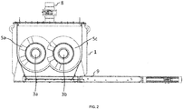
- drawing FIG.2 shows a mixer with several mixing zones in frontal view in cross section.
- drawing FIG.3 shows an open mixer with several mixing zones in top view.
- drawing FIG.4 shows a closed mixer with several mixing zones in top view.
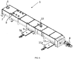
- drawing FIG.5 shows a closed mixer with several mixing zones in view obliquely from above.
- FIG.6 shows a mixer with several mixing zones in lateral view with two filters.
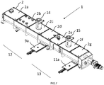
- FIG.7 shows the closed mixer with several mixing zones with two filters in view obliquely from above.
- FIG.1 shows a mixer ( 1 ) having a housing ( 2 ), further comprising a mixer shaft ( 3 ) which extends into the interior of the housing ( 2 ), and with a motor ( 4 ) as a drive for the mixer shaft ( 3 ) is driven.
- the mixer shaft ( 3 ) contains fixed in helical arrangement non-continuous conveyor moldings ( 5a ).
- an inlet ( 6 ) for the polymer granules is shown, further in the transport direction ( 7 ) arranged downstream three inlets ( 8 ) for a first additive, a first outlet for polymer granules ( 9 ), which mixes with the first additive was a second inlet ( 10 ) for a second additive and a second outlet ( 11 ) for polymer granules, which was mixed with the second additive.
- This additive taken from the second outlet ( 11 ) additionally contains the first additive.
- the first mixing zone ( 12 ) is defined by the inlets ( 8 ) for the first additive and the polymer granulate outlet ( 9 ) following in the direction of transport, which has been mixed with the first additive.
- the second mixing zone ( 13 ) is defined by the second additive inlet ( 10 ) and the polymer granule outlet ( 11 ) in the direction of transport, which has been mixed with the second additive.
- FIG.2 shows a mixer ( 1 ) with several mixing zones ( 12 , 13 ) in frontal view in cross section. Shown are two mixer shafts ( 3a , 3b ), an inlet ( 8 ) for an additive and an outlet ( 9 ) for polymer granules with the additive. At the first mixer shaft ( 3a ) non-continuous conveyor moldings ( 5a ) are attached. These transport and mix the polymer granulate with the respective additive. On the second mixer shaft ( 3b ), the section with the continuous screw conveyor ( 5c ) can be seen.
- FIG.3 shows an open mixer ( 1 ) from above, which comprises a plurality of mixing zones ( 12 , 13 ). You can see two mixer shafts ( 3a , 3b ). On the mixer shafts ( 3 ) non-continuous conveyor parts ( 5a ) are applied within the first mixing zone ( 12 ) and the second mixing zone ( 13 ). In contrast, a section with a continuous conveyor screw ( 5c ) is arranged between the first mixing zone ( 12 ) and the second mixing zone ( 13 ). Thereby, the additive which is added to the second mixing zone ( 13 ) can not be mixed back into the first mixing zone ( 12 ).
- the mixer shafts ( 3a , 3b ) are in opposite directions due to the Helixcoolsinns thereon conveyor moldings ( 5a ) and the screw conveyor ( 5c ). Also visible is the motor ( 4 ) for driving the mixer screws ( 3a , 3b ) and two outlets ( 9 , 11 ) for polymer granules with the additive, which are located behind a respective mixing zone are located.
- the outlets ( 9 , 11 ) are arranged here below the housing ( 2 ) of the mixer ( 1 ). These can be closed with gate valves ( 9a , 11a ).
- FIG.4 shows a closed mixer ( 1 ) from above, which contains a plurality of mixing zones ( 12 , 13 ). You can see the housing ( 2 ) and the motor ( 4 ) to drive the mixer screws ( 3 ). Furthermore, one sees the inlet ( 6 ) for the unmixed polymer granules, a total of six inlets ( 8 ) for the first additive and the gate valve ( 9a ) for a first outlet ( 9 ) for polymer granules which has been mixed with the first additive. In the transport direction ( 7 ) below, one sees an inlet ( 10 ) for the second additive and the gate valve ( 11b ) for an outlet ( 11 ) for the polymer granules which has been mixed with the second additive.
- FIG.5 shows a closed mixer ( 1 ) in an oblique view from above with an inlet ( 6 ) for polymer granules, another six arranged in the transport direction inlet openings ( 8 ) for the first additive, a first outlet ( 9 ) for polymer granules, which with the first additive with a gate valve ( 9a ), another inlet ( 10 ) for the second additive and a second outlet ( 11 ) with a gate valve (11a) for polymer granules which has been mixed with the second additive.
- FIG.6 shows a mixer ( 1 ), which on the housing ( 2 ) with two filters ( 14 , 15 ) is equipped for gas exchange during transport and mixing of the polymer granules.
- the filters ( 14 , 15 ) are equipped with filter cartridges ( 14a , 15a ).
- FIG.7 shows the mixer ( 1 ) with two filters ( 14 , 15 ) in view obliquely from above.
- the mixer ( 1 ) is shown here in a closed view and divided by the housing ( 2 ) into segments ( 2a - 2g ).
- the first filter ( 14 ) is placed within the first mixing zone ( 12 ) on a central segment ( 2c ) in the middle. This thereby enables gas exchange in the first mixing zone ( 12 ).
- the second filter ( 15 ) is placed within the second mixing zone ( 13 ) on a central segment ( 2f ) in the middle. This thereby enables a gas exchange in the second mixing zone ( 13 ).
- Also designated here are the gate valves ( 9a , 11a ) for the outlets ( 9 , 11 ).
Landscapes
- Chemical & Material Sciences (AREA)
- Chemical Kinetics & Catalysis (AREA)
- Engineering & Computer Science (AREA)
- Mechanical Engineering (AREA)
- Health & Medical Sciences (AREA)
- General Health & Medical Sciences (AREA)
- Toxicology (AREA)
- Processing And Handling Of Plastics And Other Materials For Molding In General (AREA)
- Medicinal Chemistry (AREA)
- Polymers & Plastics (AREA)
- Organic Chemistry (AREA)
- Mixers Of The Rotary Stirring Type (AREA)
Abstract
Description
- Die Erfindung richtet sich auf eine Vorrichtung zum aufeinanderfolgenden Einbringen von Additiven in ein Polymergranulat und die Verwendung der Vorrichtung zum Mischen des Polymergranulats mit den Additiven. Die Vorrichtung besteht aus einem Mischer mit einem Gehäuse, welcher mindestens eine Mischerwelle mit daran in Helixanordnung befestigten nichtdurchgängigen Förderformteilen enthält, die durch einen Antrieb zum Transport des Polymergranulats gedreht werden, wobei der Mischer in dem Gehäuse einen Einlass für das zu vermischende Polymergranulat aufweist und mehrere aufeinanderfolgende Einlässe für das Additiv und Auslässe für das mit dem Additiv vermischte Polymergranulat, und auf jeden Einlass für das Additiv ein Auslass für das mit dem Additiv vermischte Polymergranulat folgt, so dass sich in dem Mischer zwei oder mehrere Mischzonen bilden, und wobei zwischen mindestens zwei Mischzonen auf der Oberfläche der Mischwellen statt der nichtdurchgängigen Förderformteile ein Abschnitt mit einer durchgängigen Förderschnecke angeordnet ist, der für rückströmende Feststoffe aus der darauffolgenden Mischzone nicht durchlässig ist. Die Erfindung richtet sich auch auf die Verwendung der Vorrichtung.
- Thermoplastische Massen müssen bei der Herstellung von Polymeren oftmals mit Additiven vermischt werden. Beispiele für thermoplastische Massen sind Polymergranulate. Das Vermischen der Additive mit den thermoplastischen Massen geschieht dabei in der Regel in Mischern, welche aus einem Gehäuse mit einer oder mehreren Mischerschnecken bestehen. Die Mischerschnecke wird dabei durch eine drehbare Mischerwelle gebildet, die auf ihrer Oberfläche Förderschnecken aufweist, die in einer Helixanordnung auf der Mischerwelle aufgebracht sind. Durch die Drehung wird das Polymergranulat dann innerhalb des Gehäuses transportiert. Das Gehäuse enthält an einem Ende einen Einlass für das Polymergranulat, wodurch dieses in den Mischer eingefüllt wird, einen Einlass für das Additiv und einen Auslass für das mit dem Polymergranulat vermischte Additiv. Die Mischerwelle mit den Förderschnecken wird dann gedreht, wodurch das Polymergranulat und das Additiv innerhalb des Gehäuses weiterbewegt werden und diese sich dabei vermischen.
- Oftmals ist es erforderlich, dass ein Polymergranulat durch das Mischen mit Additiven für unterschiedliche Einsatzwecke bereitgestellt werden soll. Für diese Zwecke kommen verschiedene Additive zum Einsatz, um die Polymergranulate für die unterschiedlichen Einsatzzwecke herzustellen. Dabei kann es auch vorkommen, dass Additive für die Herstellung von Polymergranulaten gewechselt werden müssen. Eine Verunreinigung des hergestellten Polymergranulates, welches mit einem Additiv versehen ist, mit einem anderen Additiv ist dabei jedoch nicht erwünscht. Eine Reinigung des Mischers ist aufwändig und muss sehr sorgfältig durchgeführt werden, so dass die Möglichkeit einer Reinigung des Mischers bei einem Wechsel des Additivs aus wirtschaftlichen Gründen oftmals ausscheidet.
- Ein Additiv, welches als Additiv für Polymergranulate sehr oft verwendet wird, ist Ruß. Dieses wird zur Schwarzfärbung von thermoplastischen Massen verwendet. Wird dieses in einem Mischer zum Mischen hinzugesetzt, so lässt sich ein herkömmlicher Mischer ohne weitere Reinigung und ohne weitere Maßnahmen ausschließlich zum Mischen mit Ruß verwenden. Dies ist wirtschaftlich sehr nachteilig, so dass nach Möglichkeiten gesucht wird, Polymergranulate auch mit anderen Additiven zu mischen, ohne dass diese mit Ruß verunreinigt werden.
- Aus diesem Grund gibt es im Stand der Technik Mischer, die mehrere Mischzonen aufweisen. Diese Mischzonen werden durch einen Einlass und einen Auslass in dem Gehäuse des Mischers gebildet, so dass eine Mischzone durch den Bereich zwischen dem Einlass des Mischers für ein Additiv und dem Auslass des Mischers für das mit dem Additiv vermischte Polymergranulat definiert wird. Durch die Aufeinanderfolge von Einlässen und Auslässen werden in Transportrichtung des Transportgutes, also des Polymergranulates, dann mehrere Mischzonen definiert. Das Additiv, dessen Verunreinigung nicht erwünscht ist, wird dann in die letzte Mischzone gegeben. Wird also beispielsweise Ruß zugegeben, so wird dieses in Transportrichtung in die letzte Mischzone gegeben. Das unvermischte Polymergranulat wird dabei in der Regel in einen separaten Einlass in Transportrichtung am Anfang des Mischers zugegeben, da dadurch eine verbesserte Vermischung mit dem Additiv erreicht wird.
- Das Dokument
US3632256A beschreibt einen Extruder oder Mischer zur Vermischung von Kunststoffen mit Additiven, wobei der Extruder oder Mischer mehrere Extruderwellen in einem Extrudergehäuse aufweist, welches eine Vielzahl von Einlässen für Additive und eine Vielzahl von Auslässen für den Auslass des bemischten Kunststoffmaterials enthält, so dass eine Vielzahl von getrennten Mischzonen in Aufeinanderfolge entlang der Länge des Extrudergehäuses gebildet wird, wobei der Mischer schraubenförmige Mittel besitzt, und die schraubenförmigen Mittel zwischen den Mischzonen eine Drehsinnumkehr aufweisen, und wobei die Extruderwellen miteinanderläufig, gegenläufig oder ineinander verzahnt sind. - Das Dokument
US4443109A beschreibt eine Vorrichtung und ein Verfahren zur automatischen und kontinuierlichen Zugabe und zum automatischen und kontinuierlichen Mischen und Verschneiden von teilchenförmigem Material, wobei das teilchenförmige Material zunächst ohne Vermischen über ein Zugaberohr in eine Mischkammer durch Schwerkraft gegeben wird, so dass sich eine bestimmte Materialhöhe einstellt, und dann über drehbare schraubenförmige Transportmittel verschiedene Additive hinzugegeben werden, so dass sich innerhalb der Kammer ein Mischgleichgewicht einstellt, und wobei die Additive innerhalb der Mischkammer oberhalb der Materialhöhe zugegeben werden, so dass sich die zugegebenen verschiedenen Additive in der Mischkammer mit dem teilchenförmigen Material vermischen und dadurch die endgültige Zusammensetzung der erhaltenen Mischung bestimmen. Das Zugaberohr in die Mischkammer ist in einer Ausführungsform der Erfindung ebenfalls drehbar. - Das Dokument
US3897889A beschreibt eine Vorrichtung zum Dosieren, Verschneiden und Transportieren von teilchenförmigem Material, welches zwei oder mehrere Bestandteile enthält, wie beispielsweise Polymergranulat als Ausgangsmaterial, wobei die Vorrichtung einen ersten Einlass zur Zugabe von mehreren Additiven aufweist, der für die einzelnen Additive verschiedene Dosierungsventile enthält, und eine Förderschnecke in einem Gehäuse, auf die die verschiedenen Additive aufgegeben werden, wobei die Förderschnecke an ihrem Auslassende eine abwärts gerichtete Auslassöffnung aufweist, und wobei in Transportrichtung des teilchenförmigen Materials ein weiterer Einlass angeordnet ist, durch den ein konzentrierter Farbstoff als zusätzliches Additiv auf die Förderschnecke aufgegeben wird, wobei das zusätzliche Additiv über eine vibrierende Rutsche durch Schwerkrafteinwirkung auf die Förderschnecke gegeben wird. Die Vorrichtung ist platzsparend und kann direkt und in einfacher Weise auf Extruder aufgesetzt werden. - Die Mischer aus dem Stand der Technik, die mehrere Mischzonen aufweisen, weisen jedoch das Problem auf, dass es zwischen den Mischzonen trotz aller Vorsichtsmaßnahmen trotzdem zu einer Vermischung des Polymergranulates mit dem Additiv kommt, welches in der darauffolgenden Mischzone zu gegeben wird. So wandert insbesondere aufgrund nichtidealen Feststoffverhaltens ein Additiv, welches über einen Einlass für eine Mischzone zugegeben wird, entgegen der Transportrichtung über die Mischschnecke in die vorhergehende Mischzone. Dies ist unerwünscht, da dadurch die Vorteile eines Mischers mit mehreren Mischzonen, der zum Zwecke der Zugabe unterschiedlicher Additive ohne deren Rückvermischung bereitgestellt wird, geschmälert oder gar zunichte gemacht werden.
- Ruß als Additiv beispielsweise hat nicht nur Feststoffeigenschaften, sondern ist auch von öliger Konsistenz. Dadurch wandert dieses nach einiger Zeit der Zugabe die Mischschnecke entgegen der Transportrichtung aufwärts in die vorhergehende Mischzone. In der vorhergehenden Mischzone wird dann das Polymergranulat, welches kein Ruß enthalten soll, bereits durch geringe Spuren Ruß in unerwünschter Weise schwarz gefärbt. Da ein Mischer mit mehreren Mischzonen verwendet wird, um diesen nicht für die ausschließliche Zugabe von Ruß vorhalten zu müssen und auch nicht schwarz gefärbte Polymergranulate verarbeiten zu können, ist die Rückvermischung des unverfärbten Polymergranulates durch Ruß über die Mischschnecke nicht erwünscht.
- Es besteht deshalb die Aufgabe, einen Mischer zur Verfügung zu stellen, welcher die Zugabe von verschiedenen Additiven in mehreren Mischzonen zulässt und welcher die Rückvermischung eines Additivs in die vorhergehende Mischzone über die Mischschnecke entgegen der Transportrichtung auch über längere Zeit der Zugabe vermeidet. Dadurch erhielte man bei der auch bei einer längeren Zugabezeit eine verbesserte Produktqualität und kann die Möglichkeiten eines Mischers mit mehreren Mischzonen besser ausnutzen.
- Die Erfindung löst diese Aufgabe durch einen Mischer mit mehreren Mischzonen, in dem die Mischzonen zwischen jeweils mindestens einem Einlass und mindestens einem Auslass in dem Mischergehäuse angeordnet sind, und wobei auf der Mischerwelle in mindestens einer Mischzone in Helixanordnung nichtdurchgängige Förderformteile angeordnet sind, die einen Transport und eine Durchmischung des Polymergranulates bewirken und zwischen mindestens zwei Mischzonen auf eine begrenzte Distanz auf der Mischwelle eine durchgängige Förderschnecke vorhanden ist, die einen Transport bewirkt und eine Rückvermischung des in der nachfolgenden Mischzone zugegebenen Additivs vermeidet.
- Dieser Mischer bietet den Vorteil eines Mischers mit mehreren Mischzonen, durch den mehrere unterschiedliche Additive zugegeben werden können, ohne dass eine Vermischung der einzelnen Additive in dem Polymergranulat erfolgt, wobei gleichzeitig die unerwünschte Rückvermischung der Additive über die Mischwelle in die vorhergehende Mischzone vermieden wird. Dadurch wird insgesamt auch eine bessere Wirtschaftlichkeit des Herstellprozesses von thermoplastischen Massen mit Additiven erreicht. Durch die nichtdurchgängigen Förderelemente wird außerdem eine bessere Durchmischung im Vergleich zu den durchgängigen Förderschnecken erreicht.
- Der hier beschriebene Mischer ist insbesondere zur Beaufschlagung von Polymergranulat in dem Mischer mit verschiedenen Additiven geeignet, kann jedoch prinzipiell zur Vermischung beliebiger Feststoffe mit beliebigen verschiedenen Additiven genutzt werden.
- Beansprucht wird insbesondere eine Vorrichtung zum aufeinanderfolgenden Einbringen von Additiven in ein Polymergranulat, umfassend
- einen Mischer, welcher ein Gehäuse und mindestens eine Mischerwelle,
- mindestens eine Einlassöffnung für ein Polymergranulat,
- mindestens eine Einlassöffnung für ein erstes Additiv, welche sich in Transportrichtung abwärts von der Einlassöffnung für das Polymergranulat befindet,
- mindestens eine Auslassöffnung für das mit dem ersten Additiv gemischte Polymergranulat, welche in Transportrichtung abwärts von der Einlassöffnung für das Polymergranulat und von der Einlassöffnung für das erste Additiv angeordnet ist, so dass sich eine erste Mischzone bildet,
- mindestens eine zweite Einlassöffnung für ein zweites Additiv, welche sich in Transportrichtung abwärts von der Einlassöffnung für das Polymergranulat, der ersten Einlassöffnung für das erste Additiv und der Auslassöffnung für das mit dem ersten Additiv gemischte Polymergranulat befindet,
- mindestens eine zweite Auslassöffnung für das mit dem zweiten Additiv gemischte Polymergranulat, welche sich in Transportrichtung abwärts von der Einlassöffnung für das Polymergranulat, der ersten Einlassöffnung für das erste Additiv, der Auslassöffnung für das mit dem ersten Additiv gemischte Polymergranulat und der zweiten Einlassöffnung für das zweite Additiv befindet, so dass sich eine zweite Mischzone bildet,
- Antriebseinheiten zum Antrieb der mindestens einen Mischerwelle, und welche dadurch gekennzeichnet ist, dass
- innerhalb der ersten Mischzone auf der Oberfläche der Mischerwelle in Helixanordnung Förderformteile befestigt sind, die einen Transport und eine Durchmischung des Polymergranulates bewirken, und
- zwischen der Auslassöffnung für das mit dem ersten Additiv gemischte Polymergranulat und der Einlassöffnung für das zweite Additiv zwischen den Mischzonen auf der Oberfläche der Mischerwelle ein Abschnitt mit einer durchgängigen Förderschnecke angeordnet ist, der für rückströmende Feststoffe aus der darauffolgenden Mischzone nicht durchlässig ist, und
- in der darauffolgenden Mischzone wiederum auf der Oberfläche der Mischerwelle in Helixanordnung nichtdurchgängige Förderformteile befestigt sind, die einen Transport und eine Durchmischung des Polymergranulates bewirken.
- In einer Ausführungsform der Erfindung handelt es sich bei den Förderformteilen um in Richtung der Helixanordnung geradlinige Leitbleche. Dadurch wird eine besonders schonende Durchmischung des Polymergranulates mit den Additiven erreicht. In einer weiteren Ausführungsform der Erfindung handelt es sich bei den Förderformteilen um in Helixanordnung gebogene Schaufeln. Dadurch wird eine besonders gründliche Durchmischung des Polymergranulates mit den Additiven erreicht.
- Die Förderformteile sind auf der Oberfläche der Mischerwelle bevorzugt mittig angeordnet. Dadurch lässt sich eine gute Durchmischung der Additive mit dem Polymergranulat erreichen.
- In einer weiteren Ausführungsform der Erfindung schließen sich an die zweite Mischzone in gleicher Weise eine oder mehrere weitere Mischzonen an. In diesem Fall sind mehrere Einlässe und Auslässe vorhanden, und zwar mindestens jeweils soviele, wie Mischzonen vorhanden sind. Zwischen einem Einlass für ein Additiv und einem Auslass für das mit dem ersten Additiv vermischte Polymergranulat wird dann jeweils eine Mischzone gebildet.
- Im Rahmen der Erfindung ist es möglich, dass innerhalb einer weiteren Mischzone auf der Oberfläche der Mischerwelle in Helixanordnung nichtdurchgängige Förderformteile befestigt sind, die einen Transport und eine Durchmischung des Polymergranulates bewirken, und zwischen mindestens zwei weiteren Mischzonen ein Abschnitt mit einer durchgängigen Förderschnecke angeordnet ist, der für rückströmende Feststoffe aus der darauffolgenden Mischzone nicht durchlässig ist. Dadurch lässt sich die erfindungsgemäße Vorrichtung vorteilhaft für die Zugabe mehrerer Additive ohne Rückvermischung nutzen.
- In einer Ausführungsform der Erfindung umfasst der Mischer zwei oder mehrere Mischerwellen. Diese können gegeneinander gleichläufig oder gegenläufig sein. Diese können auch miteinander verzahnt sein. Durch die Verwendung zweier oder mehrerer Mischerwellen wird ein schnellerer Transport des Polymergranulates oder eine verbesserte Durchmischung des Polymergranulates mit den Additiven ermöglicht. Zwei oder mehrere Mischerwellen können insbesondere bei sehr zähem und schwierig durch eine Mischerschnecke zu transportierendem Polymergranulat von Vorteil sein, da dann eine höhere Kraft auf das Polymergranulat wirkt.
- Werden zwei oder mehr Mischerwellen in dem Mischer der vorliegenden Erfindung genutzt, so können auch die weiteren Mischerwellen innerhalb mindestens einer Mischzone mit nichtdurchgängigen Förderformteilen ausgestattet sein, die einen Transport und eine Durchmischung des Polymergranulates bewirken, und zwischen den mindestens zwei Mischzonen ein Abschnitt mit einer durchgängigen Förderschnecke angeordnet sein, der für rückströmende Feststoffe aus der darauffolgenden Mischzone nicht durchlässig ist. Dadurch lassen sich auch bei zwei oder mehreren Mischerwellen die Vorteile der erfindungsgemäßen Vorrichtung nutzen.
- Auch die Einlässe und die Auslässe können für eine Mischzone mehrfach vorhanden sein. In diesem Fall wird dann über jeden Einlass für eine Mischzone das gleiche Additiv in den Mischer eingelassen und über jeden Auslass das mit dem jeweiligen Additiv versehene Polymergranulat aus dem Mischer entnommen. Dies kann insbesondere bei mehreren eingesetzten Mischerwellen sinnvoll sein, um eine bessere Aufgabe des jeweiligen Additivs über den gesamten Mischer und eine schnellere Entnahme des mit dem jeweiligen Additiv vermischten Polymergranulates zu erreichen. Die Ein- und Auslässe können je nach Bedarf auch verschließbar sein.
- In einer weiteren Ausführungsform der Erfindung ist wenigstens einer der Auslässe für das mit dem jeweiligen Additiv vermischte Polymer mit einem Absperrschieber verschließbar. Dadurch kann verhindert werden, dass bei einer ungeleichmäßigen Zugabe des Polymergranulates oder eines Additivs Material über den Auslass in den Mischer zurückgesogen und unerwünscht mittransportiert wird.
- An dem Mischer der vorliegenden Erfindung können auch Einrichtungen zum Gasausgleich und zur Reinigung der abgelassenen Gase ausgeordnet sein, die einen Gasaustausch des Mischers mit der Umgebung ermöglichen. Dies können insbesondere Filter für Feinstäube sein.
- Die Anordnung des oder der Filter kann dabei beliebig sein. So ist es im Rahmen der Erfindung möglich, dass der Mischer in Segmente unterteilt ist, und sich zwischen dem Einlass oder den Einlässen für eine Mischzone und dem Auslass oder den Auslässen für die Mischzone mittig ein Segment befindet, und der Filter für Feinstäube genau in diesem Segment mittig und auf dem Mischer angeordnet ist. Dadurch ist die Wirkungsweise des Filters für diese Mischzone optimal.
- Der oben beschriebene Mischer kann weiterhin die üblichen Begleitaggregate und Begleiteinrichtungen enthalten, die zum Betrieb von Mischern erforderlich sind. Hierzu gehören beispielsweise Motoren als Antriebe, Ventile, Leitungen, Messsensoren, Trichter, Heizungen, Transportbänder oder Steuerungseinrichtungen.
- Beansprucht wird auch die Verwendung des beschriebenen Mischers für die Vermischung von Polymergranulaten mit verschiedenen Additiven.
- Beansprucht wird insbesondere die Verwendung des beschriebenen Mischers mit verschiedenen Mischzonen und mindestens einer Mischwelle, auf der auf der Oberfläche in Helixanordnung nichtdurchgängige Förderformteile befestigt sind, die einen Transport und eine Durchmischung des Polymergranulates bewirken, wobei zwischen mindestens zwei Mischzonen auf der Oberfläche der Mischerwelle keine nichtdurchgängigen Förderformteile, sondern stattdessen ein Abschnitt mit einer durchgängigen Förderschnecke angeordnet ist, der für rückströmende Feststoffe aus der darauffolgenden Mischzone nicht durchlässig ist, wobei dieser zum Mischen eines Polymergranulates mit zwei verschiedenen Additiven genutzt wird. Durch die Verwendung des Mischers lässt sich eine unerwünschte Rückvermischung der verschiedenen Additive in die jeweils vorhergehende Mischzone vermeiden, so dass die einzelnen Polymergranulate mit den verschiedenen Additiven nicht verunreinigt werden.
- In einer Ausführungsform der Verwendung der Erfindung handelt es sich bei dem zweiten Additiv um Ruß. Die Verwendung des oben beschrieben Mischers ist bei der Verwendung von Ruß als zweitem Additiv sinnvoll, weil dadurch wie bei den Mischern mit mehreren Mischzonen eine Verunreinigung des frischen Polymergranulates mit dem Ruß vor Erreichen der Mischzone mit dem Ruß vermieden wird, indem eine Rückvermischung des Rußes in die vorherigen Mischzonen nicht stattfindet. Dadurch werden ungleichmäßig schwarz gefärbte Polymergranulate mit einer schlechteren Qualität vermieden.
- Der oben beschriebene Mischer kann auch zum Mischen eines Polymergranulats mit drei oder mehreren verschiedenen Additiven genutzt werden. Dabei kann es sich bei einem einem der Additive um Ruß handeln, welches dann in der letzten Mischzone zugeführt wird. Die Ausführung erfolgt prinzipiell mit demselben Mischer, der zwei verschiedene Additive zumischt. Im Idealfall weist der verwendete Mischer für jedes zugemischte Additiv eine eigene Mischzone auf. Es ist jedoch im Rahmen der Erfindung auch möglich, zwei oder mehrere Additive in eine Mischzone zuzugeben.
- Die Erfindung besitzt den Vorteil, einen Mischer mit mehreren Mischzonen zur Verfügung zu stellen, durch den sich in verschiedenen Mischzonen verschiedene Additive in ein Polymergranulat einmischen lassen und durch den eine unerwünschte Rückvermischung des in einer Mischzone zugegebenen Additivs in die vorhergehende Mischzone vermieden wird. Dadurch wird insgesamt eine höhere Produktqualität und eine bessere Wirtschaftlichkeit des Herstellprozesses für thermoplastische Massen erreicht. Bei der Verwendung von Ruß wird auch nach längerer Zugabezeit kein farbloses, mit Additiven vermischtes Polymergranulat mit Ruß verunreinigt.
- Die Erfindung wird anhand von sieben Zeichnungen weiter dargestellt, wobei die Zeichnungen nur Ausführungsformen der Erfindung darstellen und diese die Erfindung in keiner Weise beschränken.
- Zeichnung
FIG.1 zeigt einen Mischer mit mehreren Mischzonen in seitlicher Ansicht. ZeichnungFIG.2 zeigt einen Mischer mit mehreren Mischzonen in frontaler Ansicht im Querschnitt. ZeichnungFIG.3 zeigt einen geöffneten Mischer mit mehreren Mischzonen in Ansicht von oben. ZeichnungFIG.4 zeigt einen geschlossenen Mischer mit mehreren Mischzonen in Ansicht von oben. ZeichnungFIG.5 zeigt einen geschlossenen Mischer mit mehreren Mischzonen in Ansicht schräg von oben.FIG.6 zeigt einen Mischer mit mehreren Mischzonen in seitlicher Ansicht mit zwei Filtern.FIG.7 zeigt den geschlossenen Mischer mit mehreren Mischzonen mit zwei Filtern in Ansicht schräg von oben. -
FIG.1 zeigt einen Mischer (1), der ein Gehäuse (2) aufweist, weiterhin eine Mischerwelle (3), die sich in das Innere des Gehäuses (2) erstreckt, und die mit einem Motor (4) als Antrieb für die Mischerwelle (3) angetrieben wird. Die Mischerwelle (3) enthält darauf befestigt in Helixanordnung nichtdurchgängige Förderformteile (5a). In dem Gehäuse (2) ist ein Einlass (6) für das Polymergranulat gezeigt, weiterhin in Transportrichtung (7) abwärts angeordnet drei Einlässe (8) für ein erstes Additiv, ein erster Auslass für Polymergranulat (9), welches mit dem ersten Additiv vermischt wurde, einen zweiten Einlass (10) für ein zweites Additiv und einen zweiten Auslass (11) für Polymergranulat, welches mit dem zweiten Additiv vermischt wurde. Dieses aus dem zweiten Auslass (11) entnommene Additiv enthält zusätzlich das erste Additiv. Durch die Einlässe (8) für das erste Additiv und den in Transportrichtung folgenden Auslass (9) für Polymergranulat, welches mit dem ersten Additiv vermischt wurde, wird die erste Mischzone (12) definiert. Durch den Einlass (10) für das zweite Additiv und den in Transportrichtung folgenden Auslass (11) für Polymergranulat, welches mit dem zweiten Additiv vermischt wurde, wird die zweite Mischzone (13) definiert. Zwischen dem ersten Auslass für Polymergranulat (9), welches mit dem ersten Additiv vermischt wurde und dem zweiten Einlass (10) für ein zweites Additiv befindet sich ein ein Abschnitt (5b) mit einer durchgängigen Förderschnecke (5c). Dieser ist für zurückfließendes zweites Additiv aus dem zweiten Einlass (10) nicht durchlässig. Dadurch kann es nicht zu einer Rückvermischung des zweiten Additivs aus der zweiten Mischzone (13) in die erste Mischzone (12) kommen. -
FIG.2 zeigt einen Mischer (1) mit mehreren Mischzonen (12,13) in frontaler Ansicht im Querschnitt. Gezeigt sind zwei Mischerwellen (3a,3b), ein Einlass (8) für ein Additiv und ein Auslass (9) für Polymergranulat mit dem Additiv. An der ersten Mischerwelle (3a) sind nichtdurchgängige Förderformteile (5a) befestigt. Diese transportieren und mischen das Polymergranulat mit dem jeweiligen Additiv. An der zweiten Mischerwelle (3b) ist der Abschnitt mit der durchgängigen Förderschnecke (5c) zu sehen. -
FIG.3 zeigt einen geöffneten Mischer (1) von oben, welcher mehrere Mischzonen (12,13) umfasst. Zu sehen sind zwei Mischerwellen (3a,3b). Auf den Mischerwellen (3) sind innerhalb der ersten Mischzone (12) und der zweiten Mischzone (13) nichtdurchgängige Förderformteile (5a) aufgebracht. Zwischen der ersten Mischzone (12) und der zweiten Mischzone (13) ist hingegen ein Abschnitt mit einer durchgängigen Förderschnecke (5c) angeordnet. Dadurch kann das Additiv, welches in die zweite Mischzone (13) zugegeben wird, nicht in die erste Mischzone (12) zurückvermischt werden. Die Mischerwellen (3a,3b) sind aufgrund des Helixdrehsinns der darauf Förderformteile (5a) und der Förderschnecke (5c) gegenläufig. Zu sehen ist auch der Motor (4) zum Antrieb der Mischerschnecken (3a,3b) und zwei Auslässe (9,11) für Polymergranulat mit dem Additiv, welche sich hinter jeweils einer Mischzone befinden. Die Auslässe (9,11) sind hier unterhalb des Gehäuses (2) des Mischers (1) angeordnet. Diese sind mit Absperrschiebern (9a,11a) verschließbar. -
FIG.4 zeigt einen geschlossenen Mischer (1) von oben, welcher mehrere Mischzonen (12,13) enthält. Zu sehen sind das Gehäuse (2) und der Motor (4) zum Antrieb der Mischerschnecken (3). Weiterhin sieht man den Einlass (6) für das unvermischte Polymergranulat, insgesamt sechs Einlässe (8) für das erste Additiv und den Absperrschieber (9a) für einen ersten Auslass (9) für Polymergranulat, welches mit dem ersten Additiv vermischt wurde. In Transportrichtung (7) nachfolgend sieht man einen Einlass (10) für das zweite Additiv und den Absperrschieber (11b) für einen Auslass (11) für das Polymergranulat, welches mit dem zweiten Additiv vermischt wurde. -
FIG.5 zeigt einen geschlossenen Mischer (1) in Ansicht schräg von oben mit einem Einlass (6) für Polymergranulat, weitere sechs in Transportrichtung nachfolgend angeordnete Einlassöffnungen (8) für das erste Additiv, einen ersten Auslass (9) für Polymergranulat, welches mit dem ersten Additiv vermischt wurde, mit einem Absperrschieber (9a), einen weiteren Einlass (10) für das zweite Additiv und einen zweiten Auslass (11) mit einem Absperrschieber (11a) für Polymergranulat, welches mit dem zweiten Additiv vermischt wurde. -
FIG.6 zeigt einen Mischer (1), welcher auf dem Gehäuse (2) mit zwei Filtern (14,15) zum Gasaustausch während des Transportes und der Mischung des Polymergranulates ausgestattet ist. Dadurch kann es während des Transportes und der Mischung des Polymergranulates nicht zu einem unerwünschten Druckaufbau im Mischer (1) kommen. Bezeichnet sind hier weiter nur das Gehäuse (2), die Mischwelle (3), die nichtdurchgängigen Förderformteile (5a) und der Abschnitt mit der durchgängigen Förderschnecke (5c). Die Filter (14,15) sind mit Filtereinsätzen (14a,15a) ausgestattet. -
FIG.7 zeigt den Mischer (1) mit zwei Filtern (14,15) in Ansicht schräg von oben. Der Mischer (1) ist hier in geschlossener Ansicht gezeigt und durch das Gehäuse (2) in Segmente (2a-2g) unterteilt. Der erste Filter (14) ist innerhalb der ersten Mischzone (12) auf einem mittigen Segment (2c) in der Mitte aufgesetzt. Dieser ermöglicht dadurch in der ersten Mischzone (12) einen Gasaustausch. Der zweite Filter (15) ist innerhalb der zweiten Mischzone (13) auf einem mittigen Segment (2f) in der Mitte aufgesetzt. Dieser ermöglicht dadurch in der zweiten Mischzone (13) einen Gasaustausch. Bezeichnet sind hier außerdem die Absperrschieber (9a,11a) für die Auslässe (9,11).Bezugszeichenliste 1 Mischer 2 Gehäuse 3 Mischerwelle 3a,3b Zwei verschiedene Mischerwellen 4 Motor 5a Nichtdurchgängige Förderformteile in Helixanordnung 5b Abschnitt mit durchgängiger Förderschnecke 5c Durchgängige Förderschnecke in Helixanordnung 6 Einlass für Polymergranulat 7 Transportrichtung 8 Einlass für erstes Additiv 9 Erster Auslass für Polymergranulat mit erstem Additiv 9a Absperrschieber für den ersten Auslass 10 Einlass für zweites Additiv 11 Zweiter Auslass für Polymergranulat mit zweitem Additiv 11a Absperrschieber für den zweiten Auslass 12 Erste Mischzone 13 Zweite Mischzone 14 Erster Filter 14a Filtereinsatz für ersten Filter 15 Zweiter Filter 15a Filtereinsatz für zweiten Filter
Claims (15)
- Vorrichtung (1) zum aufeinanderfolgenden Einbringen von Additiven in ein Polymergranulat, umfassend• einen Mischer (1), welcher ein Gehäuse (2) und mindestens eine Mischerwelle (3),• mindestens eine Einlassöffnung (6) für ein Polymergranulat,• mindestens eine Einlassöffnung (8) für ein erstes Additiv, welche sich in Transportrichtung (7) abwärts von der Einlassöffnung (6) für das Polymergranulat befindet,• mindestens eine Auslassöffnung (9) für das mit dem ersten Additiv gemischte Polymergranulat, welche in Transportrichtung (7) abwärts von der Einlassöffnung (6) für das Polymergranulat und von der Einlassöffnung (8) für das erste Additiv angeordnet ist, so dass sich eine erste Mischzone (12) bildet,• mindestens eine zweite Einlassöffnung (10) für ein zweites Additiv, welche sich in Transportrichtung (7) abwärts von der Einlassöffnung (6) für das Polymergranulat, der ersten Einlassöffnung (8) für das erste Additiv und der Auslassöffnung (9) für das mit dem ersten Additiv gemischte Polymergranulat befindet,• mindestens eine zweite Auslassöffnung (11) für das mit dem zweiten Additiv gemischte Polymergranulat, welche sich in Transportrichtung (7) abwärts von der Einlassöffnung (6) für das Polymergranulat, der ersten Einlassöffnung (8) für das erste Additiv, der Auslassöffnung (9) für das mit dem ersten Additiv gemischte Polymergranulat und der zweiten Einlassöffnung (10) für das zweite Additiv befindet, so dass sich eine zweite Mischzone (13) bildet,• Antriebseinheiten (4) zum Antrieb der mindestens einen Mischerwelle (3),dadurch gekennzeichnet, dass• innerhalb der ersten Mischzone (12) auf der Oberfläche der Mischerwelle (3) in Helixanordnung nichtdurchgängige Förderformteile (5a) befestigt sind, die einen Transport und eine Durchmischung des Polymergranulates bewirken, und• zwischen der Auslassöffnung (9) für das mit dem ersten Additiv gemischte Polymergranulat und der Einlassöffnung (10) für das zweite Additiv zwischen den Mischzonen (12,13) auf der Oberfläche der Mischerwelle (3) ein Abschnitt mit einer durchgängigen Förderschnecke (5c) angeordnet ist, der für rückströmende Feststoffe aus der darauffolgenden Mischzone (13) nicht durchlässig ist, und• in der darauffolgenden Mischzone (13) wiederum auf der Oberfläche der Mischerwelle (3) in Helixanordnung nichtdurchgängige Förderformteile (5a) befestigt sind, die einen Transport und eine Durchmischung des Polymergranulates bewirken.
- Vorrichtung (1) nach Anspruch 1, dadurch gekennzeichnet, dass es sich bei den nichtdurchgängigen Förderformteilen (5a) um in Richtung der Helixanordnung geradlinige Leitbleche handelt.
- Vorrichtung (1) nach Anspruch 1, dadurch gekennzeichnet, dass es sich bei den nichtdurchgängigen Förderformteilen (5a) um in Helixanordnung gebogene Schaufeln handelt.
- Vorrichtung (1) nach einem der Ansprüche 1 bis 3, dadurch gekennzeichnet, dass die nichtdurchgängigen Förderformteile (5a) auf der Oberfläche der Mischerwelle (3) mittig angeordnet sind.
- Vorrichtung (1) nach einem der Ansprüche 1 bis 4, dadurch gekennzeichnet, dass sich an die zweite Mischzone (13) in gleicher Weise eine oder mehrere weitere Mischzonen anschließen.
- Vorrichtung (1) nach Anspruch 5, dadurch gekennzeichnet, dass mindestens innerhalb einer weiteren Mischzone auf der Oberfläche der Mischerwelle (3) in Helixanordnung nichtdurchgängige Förderformteile (5a) befestigt sind, die einen Transport und eine Durchmischung des Polymergranulates bewirken, und zwischen mindestens zwei weiteren Mischzonen ein Abschnitt mit einer durchgängigen Förderschnecke (5c) angeordnet ist, der für rückströmende Feststoffe aus der darauffolgenden Mischzone nicht durchlässig ist.
- Vorrichtung (1) nach einem der Ansprüche 1 bis 6, dadurch gekennzeichnet, dass der Mischer (1) zwei (3a,3b) oder mehrere Mischerwellen (3) umfasst.
- Vorrichtung (1) nach Anspruch 7, dadurch gekennzeichnet, dass auch die zweite (3b) oder die weiteren Mischerwellen innerhalb mindestens einer Mischzone mit nichtdurchgängigen Förderformteilen (5a) ausgestattet sind, die einen Transport und eine Durchmischung des Polymergranulates bewirken, und zwischen mindestens zwei Mischzonen ein Abschnitt mit einer durchgängigen Förderschnecke (5c) angeordnet ist, der für rückströmende Feststoffe aus der darauffolgenden Mischzone nicht durchlässig ist.
- Vorrichtung (1) nach einem der Ansprüche 1 bis 8, dadurch gekennzeichnet, dass wenigstens einer der Auslässe (9,11) mit einem Absperrschieber (9a,11a) verschließbar ist.
- Vorrichtung nach einem der Ansprüche 1 bis 9, dadurch gekennzeichnet, dass innerhalb mindestens einer Mischzone (12) ein Filter (14) für Feinstäube angeordnet ist, der einen Gasaustausch des Mischers (1) mit der Umgebung ermöglicht.
- Vorrichtung nach Anspruch 10, dadurch gekennzeichnet, dass der Mischer (1) in Segmente (2a-2g) unterteilt ist, und sich zwischen dem Einlass (8) oder den Einlässen für eine Mischzone (12) und dem Auslass (9) oder den Auslässen mittig ein Segment (2c) befindet, und der Filter (14) für Feinstäube genau in diesem Segment (2c) mittig und auf dem Mischer (1) angeordnet ist.
- Verwendung einer Vorrichtung (1) zum aufeinanderfolgenden Einbringen von Additiven in ein Polymergranulat nach einem der Patentansprüche 1 bis 11, dadurch gekennzeichnet, dass diese zum Mischen eines Polymergranulates mit zwei verschiedenen Additiven genutzt wird.
- Verwendung einer Vorrichtung (1) zum aufeinanderfolgenden Einbringen von Additiven in ein Polymergranulat nach Patentanspruch 12, dadurch gekennzeichnet, dass es sich bei dem zweiten Additiv um Ruß handelt.
- Verwendung einer Vorrichtung (1) zum aufeinanderfolgenden Einbringen von Additiven in ein Polymergranulat nach einem der Patentansprüche 1 bis 11, dadurch gekennzeichnet, dass diese zum Mischen eines Polymergranulats mit drei oder mehreren verschiedenen Additiven genutzt wird.
- Verwendung einer Vorrichtung (1) zum aufeinanderfolgenden Einbringen von Additiven in ein Polymergranulat nach Patentanspruch 14, dadurch gekennzeichnet, dass es sich bei einem der Additive um Ruß handelt.
Priority Applications (17)
| Application Number | Priority Date | Filing Date | Title |
|---|---|---|---|
| DK18155132.6T DK3520887T3 (da) | 2018-02-05 | 2018-02-05 | Anordning til på hinanden følgende forsyning af additiver i et polymergranulat og anvendelsen af anordningen |
| PL18155132.6T PL3520887T3 (pl) | 2018-02-05 | 2018-02-05 | Urządzenie do następującego po sobie wprowadzania dodatków do granulatu polimerowego i zastosowanie tego urządzenia |
| PT181551326T PT3520887T (pt) | 2018-02-05 | 2018-02-05 | Dispositivo para a inserção seguida de aditivos num granulado de polímero e aplicação do dispositivo |
| EP18155132.6A EP3520887B1 (de) | 2018-02-05 | 2018-02-05 | Vorrichtung zum aufeinanderfolgenden einbringen von additiven in ein polymergranulat und verwendung der vorrichtung |
| ES18155132T ES2808130T3 (es) | 2018-02-05 | 2018-02-05 | Dispositivo para la introducción sucesiva de aditivos en un granulado de polímero y uso del dispositivo |
| HUE18155132A HUE051456T2 (hu) | 2018-02-05 | 2018-02-05 | Berendezés adalékanyagoknak egy polimer granulátumba való egymás utáni behordására és a berendezés használata |
| PCT/EP2019/052214 WO2019149739A1 (de) | 2018-02-05 | 2019-01-30 | Vorrichtung zum aufeinanderfolgenden einbringen von additiven in ein polymergranulat und verwendung der vorrichtung |
| CN201980001807.8A CN110461457B (zh) | 2018-02-05 | 2019-01-30 | 用于将添加剂相继地引入聚合物颗粒中的混合器和所述混合器的应用 |
| KR1020197029346A KR102417419B1 (ko) | 2018-02-05 | 2019-01-30 | 중합체 과립 내에 첨가제를 순차적으로 도입하기 위한 장치 및 장치의 사용 |
| MYPI2019005866A MY204376A (en) | 2018-02-05 | 2019-01-30 | Device for sequentially introducing additives in a polymer granulate and use of the device |
| BR112019019909A BR112019019909A2 (pt) | 2018-02-05 | 2019-01-30 | dispositivo para introdução sucessiva de aditivos em um granulado de polímero e uso do dispositivo |
| CA3058847A CA3058847A1 (en) | 2018-02-05 | 2019-01-30 | Device for sequentially introducing additives in a polymer granulate and use of the device |
| US16/500,884 US11247185B2 (en) | 2018-02-05 | 2019-01-30 | Device for the successive introduction of additives into a polymer granulate and use of the device |
| EA202090349A EA202090349A1 (ru) | 2018-02-05 | 2019-01-30 | Устройство для последовательного введения добавок в полимерный гранулят и способ использования устройства |
| MX2019011944A MX393087B (es) | 2018-02-05 | 2019-01-30 | Dispositivo para introducir secuencialmente aditivos en un granulado polimérico y uso del dispositivo |
| JP2019555436A JP7305550B2 (ja) | 2018-02-05 | 2019-01-30 | ポリマー顆粒の中に添加剤を逐次的に導入するためのデバイス、及び、デバイスの使用 |
| HRP20201254TT HRP20201254T1 (hr) | 2018-02-05 | 2020-08-11 | Uređaj za sukcesivno unošenje aditiva u polimerni granulat i uporaba uređaja |
Applications Claiming Priority (1)
| Application Number | Priority Date | Filing Date | Title |
|---|---|---|---|
| EP18155132.6A EP3520887B1 (de) | 2018-02-05 | 2018-02-05 | Vorrichtung zum aufeinanderfolgenden einbringen von additiven in ein polymergranulat und verwendung der vorrichtung |
Publications (2)
| Publication Number | Publication Date |
|---|---|
| EP3520887A1 true EP3520887A1 (de) | 2019-08-07 |
| EP3520887B1 EP3520887B1 (de) | 2020-05-20 |
Family
ID=61163583
Family Applications (1)
| Application Number | Title | Priority Date | Filing Date |
|---|---|---|---|
| EP18155132.6A Active EP3520887B1 (de) | 2018-02-05 | 2018-02-05 | Vorrichtung zum aufeinanderfolgenden einbringen von additiven in ein polymergranulat und verwendung der vorrichtung |
Country Status (17)
| Country | Link |
|---|---|
| US (1) | US11247185B2 (de) |
| EP (1) | EP3520887B1 (de) |
| JP (1) | JP7305550B2 (de) |
| KR (1) | KR102417419B1 (de) |
| CN (1) | CN110461457B (de) |
| BR (1) | BR112019019909A2 (de) |
| CA (1) | CA3058847A1 (de) |
| DK (1) | DK3520887T3 (de) |
| EA (1) | EA202090349A1 (de) |
| ES (1) | ES2808130T3 (de) |
| HR (1) | HRP20201254T1 (de) |
| HU (1) | HUE051456T2 (de) |
| MX (1) | MX393087B (de) |
| MY (1) | MY204376A (de) |
| PL (1) | PL3520887T3 (de) |
| PT (1) | PT3520887T (de) |
| WO (1) | WO2019149739A1 (de) |
Families Citing this family (1)
| Publication number | Priority date | Publication date | Assignee | Title |
|---|---|---|---|---|
| ES2808130T3 (es) * | 2018-02-05 | 2021-02-25 | Koellemann Gmbh Foerder Und Verfahrenstechnik | Dispositivo para la introducción sucesiva de aditivos en un granulado de polímero y uso del dispositivo |
Citations (4)
| Publication number | Priority date | Publication date | Assignee | Title |
|---|---|---|---|---|
| US3632256A (en) | 1969-03-19 | 1972-01-04 | Union Carbide Corp | Extrusion-compounding apparatus |
| US3897889A (en) | 1973-04-03 | 1975-08-05 | Erich August Hindermann | Apparatus for metering, blending and conveying |
| US4443109A (en) | 1981-09-21 | 1984-04-17 | Vol-Pro Systems, Inc. | Method and apparatus for continuous feeding, mixing and blending |
| EP1203650A1 (de) * | 2000-11-03 | 2002-05-08 | General Electric Company | Verfahren und System zum Mischen von Silikonzusammensetzungen |
Family Cites Families (34)
| Publication number | Priority date | Publication date | Assignee | Title |
|---|---|---|---|---|
| DE1241417B (de) * | 1962-09-28 | 1967-06-01 | Buss Ag | Kontinuierlich arbeitende Misch- und Kneteinrichtung |
| CH434208A (de) * | 1965-08-14 | 1967-04-30 | List Heinz | Misch- und Knetmaschine mit scheibenförmigen Knetelementen |
| CH450696A (de) * | 1967-06-13 | 1968-01-31 | Buss Ag | Misch- und Kneteinrichtung |
| AT309789B (de) * | 1967-11-20 | 1973-09-10 | Buss Ag | Misch- und Knetvorrichtung für plastische Massen |
| US3652064A (en) * | 1968-03-22 | 1972-03-28 | Uniroyal Englebert Ag | Apparatus for conveying plastic material |
| US3548926A (en) * | 1968-05-10 | 1970-12-22 | William E Archer | Screw type material processor |
| US3814563A (en) * | 1969-02-25 | 1974-06-04 | French Oil Mill Machinery | Apparatus for treating elastomeric materials |
| BE760050A (fr) * | 1969-12-10 | 1971-05-17 | Buss Ag | Procede et installation pour effectuer des dispersions de colorants |
| US3672641A (en) * | 1970-09-14 | 1972-06-27 | French Oil Mill Machinery | Apparatus for removing liquids from elastomeric polymers |
| GB1399141A (en) * | 1971-08-02 | 1975-06-26 | Monsanto Co | Mixing apparatus and process |
| US3873072A (en) * | 1971-08-02 | 1975-03-25 | Monsanto Co | Melt extrusion |
| JPS549058A (en) * | 1977-06-21 | 1979-01-23 | Mitsui Polychemicals Ltd | Method of mixing addttive* etc* to thermal plastic resin |
| US4304054A (en) * | 1980-04-21 | 1981-12-08 | The B. F. Goodrich Company | Screw press for drying elastomeric polymers |
| US4416606A (en) * | 1980-10-22 | 1983-11-22 | Mitsubishi Gas Chemical Company, Inc. | Apparatus for granulating sodium percarbonate |
| US5816698A (en) * | 1996-04-15 | 1998-10-06 | Spirex Corporation | Screw and plasticating apparatus and method |
| US5932159A (en) | 1997-11-07 | 1999-08-03 | Rauwendaal Extrusion Engineering, Inc. | Screw extruder with improved dispersive mixing |
| JP4063412B2 (ja) | 1998-07-31 | 2008-03-19 | 東洋ゴム工業株式会社 | ゴムの連続混練押出し装置 |
| US6183560B1 (en) * | 1998-08-05 | 2001-02-06 | Jean-Marie Joseph Sarrasin | Particulate material blender and polisher |
| JP3231751B2 (ja) * | 2000-11-06 | 2001-11-26 | ツカサ工業株式会社 | 各種粉粒体の混合装置 |
| US6547431B1 (en) * | 2000-11-09 | 2003-04-15 | Milacron Inc. | Mixing section for a feed screw and methods of making the same |
| JP2003040261A (ja) | 2001-08-01 | 2003-02-13 | High Mold:Kk | 折畳みコンテナと折畳みコンテナ用熱可塑性樹脂組成物 |
| JP3682867B2 (ja) | 2001-11-15 | 2005-08-17 | 株式会社神戸製鋼所 | ゴムあるいはゴム系組成物の混練装置および混練方法 |
| JP3774422B2 (ja) | 2002-05-29 | 2006-05-17 | 株式会社日本製鋼所 | 混練スクリュ |
| US7144532B2 (en) * | 2002-10-28 | 2006-12-05 | Trexel, Inc. | Blowing agent introduction systems and methods |
| CA2655538C (en) * | 2006-06-20 | 2015-12-01 | Edward Beecher | A process for the manufacture of unexpanded glass-like polysaccharides |
| JP5467796B2 (ja) | 2009-04-24 | 2014-04-09 | 株式会社三和商会 | 押出機のベント装置、及び押出機による混練方法 |
| TW201119824A (en) * | 2009-06-30 | 2011-06-16 | Sumitomo Chemical Co | Method for producing resin composition, resin composition, reflection plate and light-emitting device |
| JP5804786B2 (ja) | 2011-06-13 | 2015-11-04 | 旭化成ケミカルズ株式会社 | 押出機およびそれを用いた溶融混練方法 |
| CN102407080B (zh) * | 2011-12-20 | 2013-12-04 | 中联重科股份有限公司 | 沥青混合料搅拌设备及集料预混装置 |
| TWI649180B (zh) | 2013-04-04 | 2019-02-01 | 艾朗希歐德意志有限公司 | 用於自含彈性體媒介移除揮發性組份之方法及為此目的之去揮發物設備 |
| PL2868686T3 (pl) * | 2013-11-05 | 2019-06-28 | Coperion Gmbh | Sposób i urządzenie do wytwarzania stopionego polimeru zawierającego dodatki i środki porotwórcze |
| CN206911689U (zh) * | 2017-02-13 | 2018-01-23 | 青海瑞湖生物资源开发有限公司 | 一种农产品筛选装置 |
| CN206652411U (zh) * | 2017-04-18 | 2017-11-21 | 山东汇百川新材料有限公司 | 一种碳黑生产搅拌装置 |
| ES2808130T3 (es) * | 2018-02-05 | 2021-02-25 | Koellemann Gmbh Foerder Und Verfahrenstechnik | Dispositivo para la introducción sucesiva de aditivos en un granulado de polímero y uso del dispositivo |
-
2018
- 2018-02-05 ES ES18155132T patent/ES2808130T3/es active Active
- 2018-02-05 HU HUE18155132A patent/HUE051456T2/hu unknown
- 2018-02-05 PT PT181551326T patent/PT3520887T/pt unknown
- 2018-02-05 PL PL18155132.6T patent/PL3520887T3/pl unknown
- 2018-02-05 DK DK18155132.6T patent/DK3520887T3/da active
- 2018-02-05 EP EP18155132.6A patent/EP3520887B1/de active Active
-
2019
- 2019-01-30 MX MX2019011944A patent/MX393087B/es unknown
- 2019-01-30 MY MYPI2019005866A patent/MY204376A/en unknown
- 2019-01-30 KR KR1020197029346A patent/KR102417419B1/ko not_active Expired - Fee Related
- 2019-01-30 EA EA202090349A patent/EA202090349A1/ru unknown
- 2019-01-30 US US16/500,884 patent/US11247185B2/en not_active Expired - Fee Related
- 2019-01-30 CN CN201980001807.8A patent/CN110461457B/zh not_active Expired - Fee Related
- 2019-01-30 BR BR112019019909A patent/BR112019019909A2/pt not_active Application Discontinuation
- 2019-01-30 CA CA3058847A patent/CA3058847A1/en active Pending
- 2019-01-30 JP JP2019555436A patent/JP7305550B2/ja active Active
- 2019-01-30 WO PCT/EP2019/052214 patent/WO2019149739A1/de not_active Ceased
-
2020
- 2020-08-11 HR HRP20201254TT patent/HRP20201254T1/hr unknown
Patent Citations (4)
| Publication number | Priority date | Publication date | Assignee | Title |
|---|---|---|---|---|
| US3632256A (en) | 1969-03-19 | 1972-01-04 | Union Carbide Corp | Extrusion-compounding apparatus |
| US3897889A (en) | 1973-04-03 | 1975-08-05 | Erich August Hindermann | Apparatus for metering, blending and conveying |
| US4443109A (en) | 1981-09-21 | 1984-04-17 | Vol-Pro Systems, Inc. | Method and apparatus for continuous feeding, mixing and blending |
| EP1203650A1 (de) * | 2000-11-03 | 2002-05-08 | General Electric Company | Verfahren und System zum Mischen von Silikonzusammensetzungen |
Also Published As
| Publication number | Publication date |
|---|---|
| WO2019149739A1 (de) | 2019-08-08 |
| JP2021511950A (ja) | 2021-05-13 |
| MX2019011944A (es) | 2022-06-13 |
| KR20190124774A (ko) | 2019-11-05 |
| EP3520887B1 (de) | 2020-05-20 |
| US11247185B2 (en) | 2022-02-15 |
| KR102417419B1 (ko) | 2022-07-06 |
| EA202090349A1 (ru) | 2021-01-26 |
| US20200385533A1 (en) | 2020-12-10 |
| HRP20201254T1 (hr) | 2021-02-19 |
| DK3520887T3 (da) | 2020-08-10 |
| CA3058847A1 (en) | 2019-08-08 |
| MX393087B (es) | 2025-03-24 |
| JP7305550B2 (ja) | 2023-07-10 |
| HUE051456T2 (hu) | 2021-03-01 |
| PT3520887T (pt) | 2020-08-24 |
| ES2808130T3 (es) | 2021-02-25 |
| MY204376A (en) | 2024-08-27 |
| PL3520887T3 (pl) | 2021-02-22 |
| WO2019149739A8 (de) | 2019-11-07 |
| CN110461457A (zh) | 2019-11-15 |
| CN110461457B (zh) | 2023-02-03 |
| BR112019019909A2 (pt) | 2020-04-22 |
Similar Documents
| Publication | Publication Date | Title |
|---|---|---|
| DE2400271C2 (de) | Verfahren und Vorrichtung zum Austreiben von flüchtigen Komponenten aus in Extrusionsrichtung strömendem Kunststoff | |
| DE10122462C1 (de) | Vorrichtung mit Schnecken zum Homogenisieren und/oder Dispergieren eines viskosen Stoffes und eines Feststoffes und/oder eines anderen Stoffes unterschiedlicher Viskosität | |
| EP0988955B1 (de) | Verfahren zur Einspeisung von Additiven in einen Polymerschmelzstrom | |
| DE2731301A1 (de) | Vorrichtung zum kontinuierlichen mischen | |
| DE1502335B2 (de) | Schneckenstrangprese fuer die verarbeitung von kunststoff | |
| DE2924317C2 (de) | Zweistufige Strangpreßvorrichtung für thermoplastische Formmassen, insbesondere für pulverförmige Kunststoffe | |
| DE60204101T2 (de) | Knetvorrichtung und Verfahren zum Kneten von Kautschuk oder Kautschukzusammensetzungen | |
| DE2301064B2 (de) | Extruder für plastifizierbare Kunststoffe | |
| EP0517118A1 (de) | Vorrichtung zum Plastifizieren von Kunststoff | |
| DE3519349C2 (de) | ||
| EP1025289A1 (de) | Vorrichtung zum mischen und fördern einer polymerschmelze | |
| EP3520887B1 (de) | Vorrichtung zum aufeinanderfolgenden einbringen von additiven in ein polymergranulat und verwendung der vorrichtung | |
| DE4137969C1 (de) | ||
| EP0052797B1 (de) | Verfahren und Vorrichtung zur kontinuierlichen Herstellung von Treibladungspulver | |
| EP0564884B1 (de) | Mehrwellige Schneckenmaschine mit Zahnradpumpe | |
| EP0513431B1 (de) | Vorrichtung zum Aufbereiten und Strangpressen von Werkstoffen | |
| DE3029565A1 (de) | Extruder insbesondere fuer kunststoffe und elastomere | |
| DE949162C (de) | Schnecken-Misch- und -Knetwerk | |
| EP1920822A2 (de) | Vorrichtung und Verfahren zur kontinuierlichen Mischung und Entgasung von festen und/oder flüssigen Substanzen | |
| DE2340726C2 (de) | Vorrichtung zum kontinuierlichen Dispergieren und Feinmahlen von Feststoffen in einem flüssigen Dispersionsmittel | |
| DE69505852T2 (de) | Dynamischer In-Line Mischer mit Faltelementen und perforierten Platten | |
| DE3344297A1 (de) | Vorrichtung zum extrudieren von kunstharzen | |
| DE69908471T2 (de) | Kontinuierlich arbeitende Knetmaschine | |
| EP2105201B1 (de) | Vorrichtung und Verfahren zum Mischen von viskosen oder plastischen Medien | |
| DE1224468B (de) | Mischapparatur zum Mischen von thermoplastischem polymerem Material |
Legal Events
| Date | Code | Title | Description |
|---|---|---|---|
| PUAI | Public reference made under article 153(3) epc to a published international application that has entered the european phase |
Free format text: ORIGINAL CODE: 0009012 |
|
| STAA | Information on the status of an ep patent application or granted ep patent |
Free format text: STATUS: REQUEST FOR EXAMINATION WAS MADE |
|
| 17P | Request for examination filed |
Effective date: 20190329 |
|
| AK | Designated contracting states |
Kind code of ref document: A1 Designated state(s): AL AT BE BG CH CY CZ DE DK EE ES FI FR GB GR HR HU IE IS IT LI LT LU LV MC MK MT NL NO PL PT RO RS SE SI SK SM TR |
|
| AX | Request for extension of the european patent |
Extension state: BA ME |
|
| GRAP | Despatch of communication of intention to grant a patent |
Free format text: ORIGINAL CODE: EPIDOSNIGR1 |
|
| STAA | Information on the status of an ep patent application or granted ep patent |
Free format text: STATUS: GRANT OF PATENT IS INTENDED |
|
| RBV | Designated contracting states (corrected) |
Designated state(s): AL AT BE BG CH CY CZ DE DK EE ES FI FR GB GR HR HU IE IS IT LI LT LU LV MC MK MT NL NO PL PT RO RS SE SI SK SM TR |
|
| INTG | Intention to grant announced |
Effective date: 20191030 |
|
| GRAS | Grant fee paid |
Free format text: ORIGINAL CODE: EPIDOSNIGR3 |
|
| GRAA | (expected) grant |
Free format text: ORIGINAL CODE: 0009210 |
|
| STAA | Information on the status of an ep patent application or granted ep patent |
Free format text: STATUS: THE PATENT HAS BEEN GRANTED |
|
| AK | Designated contracting states |
Kind code of ref document: B1 Designated state(s): AL AT BE BG CH CY CZ DE DK EE ES FI FR GB GR HR HU IE IS IT LI LT LU LV MC MK MT NL NO PL PT RO RS SE SI SK SM TR |
|
| REG | Reference to a national code |
Ref country code: GB Ref legal event code: FG4D Free format text: NOT ENGLISH |
|
| REG | Reference to a national code |
Ref country code: CH Ref legal event code: EP |
|
| REG | Reference to a national code |
Ref country code: DE Ref legal event code: R096 Ref document number: 502018001463 Country of ref document: DE |
|
| REG | Reference to a national code |
Ref country code: AT Ref legal event code: REF Ref document number: 1272246 Country of ref document: AT Kind code of ref document: T Effective date: 20200615 |
|
| REG | Reference to a national code |
Ref country code: DK Ref legal event code: T3 Effective date: 20200806 Ref country code: NO Ref legal event code: T2 Effective date: 20200520 |
|
| REG | Reference to a national code |
Ref country code: HR Ref legal event code: TUEP Ref document number: P20201254T Country of ref document: HR |
|
| REG | Reference to a national code |
Ref country code: SE Ref legal event code: TRGR |
|
| REG | Reference to a national code |
Ref country code: FI Ref legal event code: FGE |
|
| REG | Reference to a national code |
Ref country code: NL Ref legal event code: FP |
|
| REG | Reference to a national code |
Ref country code: PT Ref legal event code: SC4A Ref document number: 3520887 Country of ref document: PT Date of ref document: 20200824 Kind code of ref document: T Free format text: AVAILABILITY OF NATIONAL TRANSLATION Effective date: 20200810 |
|
| REG | Reference to a national code |
Ref country code: LT Ref legal event code: MG4D |
|
| REG | Reference to a national code |
Ref country code: GR Ref legal event code: EP Ref document number: 20200402330 Country of ref document: GR Effective date: 20201014 |
|
| PG25 | Lapsed in a contracting state [announced via postgrant information from national office to epo] |
Ref country code: LT Free format text: LAPSE BECAUSE OF FAILURE TO SUBMIT A TRANSLATION OF THE DESCRIPTION OR TO PAY THE FEE WITHIN THE PRESCRIBED TIME-LIMIT Effective date: 20200520 |
|
| REG | Reference to a national code |
Ref country code: SK Ref legal event code: T3 Ref document number: E 34970 Country of ref document: SK |
|
| PG25 | Lapsed in a contracting state [announced via postgrant information from national office to epo] |
Ref country code: LV Free format text: LAPSE BECAUSE OF FAILURE TO SUBMIT A TRANSLATION OF THE DESCRIPTION OR TO PAY THE FEE WITHIN THE PRESCRIBED TIME-LIMIT Effective date: 20200520 Ref country code: RS Free format text: LAPSE BECAUSE OF FAILURE TO SUBMIT A TRANSLATION OF THE DESCRIPTION OR TO PAY THE FEE WITHIN THE PRESCRIBED TIME-LIMIT Effective date: 20200520 Ref country code: BG Free format text: LAPSE BECAUSE OF FAILURE TO SUBMIT A TRANSLATION OF THE DESCRIPTION OR TO PAY THE FEE WITHIN THE PRESCRIBED TIME-LIMIT Effective date: 20200820 |
|
| PG25 | Lapsed in a contracting state [announced via postgrant information from national office to epo] |
Ref country code: AL Free format text: LAPSE BECAUSE OF FAILURE TO SUBMIT A TRANSLATION OF THE DESCRIPTION OR TO PAY THE FEE WITHIN THE PRESCRIBED TIME-LIMIT Effective date: 20200520 |
|
| PG25 | Lapsed in a contracting state [announced via postgrant information from national office to epo] |
Ref country code: SM Free format text: LAPSE BECAUSE OF FAILURE TO SUBMIT A TRANSLATION OF THE DESCRIPTION OR TO PAY THE FEE WITHIN THE PRESCRIBED TIME-LIMIT Effective date: 20200520 Ref country code: RO Free format text: LAPSE BECAUSE OF FAILURE TO SUBMIT A TRANSLATION OF THE DESCRIPTION OR TO PAY THE FEE WITHIN THE PRESCRIBED TIME-LIMIT Effective date: 20200520 Ref country code: EE Free format text: LAPSE BECAUSE OF FAILURE TO SUBMIT A TRANSLATION OF THE DESCRIPTION OR TO PAY THE FEE WITHIN THE PRESCRIBED TIME-LIMIT Effective date: 20200520 |
|
| REG | Reference to a national code |
Ref country code: HR Ref legal event code: T1PR Ref document number: P20201254 Country of ref document: HR Ref country code: HR Ref legal event code: ODRP Ref document number: P20201254 Country of ref document: HR Payment date: 20210201 Year of fee payment: 4 |
|
| REG | Reference to a national code |
Ref country code: DE Ref legal event code: R097 Ref document number: 502018001463 Country of ref document: DE |
|
| REG | Reference to a national code |
Ref country code: ES Ref legal event code: FG2A Ref document number: 2808130 Country of ref document: ES Kind code of ref document: T3 Effective date: 20210225 |
|
| REG | Reference to a national code |
Ref country code: HU Ref legal event code: AG4A Ref document number: E051456 Country of ref document: HU |
|
| PLBE | No opposition filed within time limit |
Free format text: ORIGINAL CODE: 0009261 |
|
| STAA | Information on the status of an ep patent application or granted ep patent |
Free format text: STATUS: NO OPPOSITION FILED WITHIN TIME LIMIT |
|
| 26N | No opposition filed |
Effective date: 20210223 |
|
| PG25 | Lapsed in a contracting state [announced via postgrant information from national office to epo] |
Ref country code: MC Free format text: LAPSE BECAUSE OF FAILURE TO SUBMIT A TRANSLATION OF THE DESCRIPTION OR TO PAY THE FEE WITHIN THE PRESCRIBED TIME-LIMIT Effective date: 20200520 |
|
| REG | Reference to a national code |
Ref country code: DE Ref legal event code: R079 Ref document number: 502018001463 Country of ref document: DE Free format text: PREVIOUS MAIN CLASS: B01F0003180000 Ipc: B01F0023600000 |
|
| REG | Reference to a national code |
Ref country code: HR Ref legal event code: ODRP Ref document number: P20201254 Country of ref document: HR Payment date: 20220715 Year of fee payment: 5 |
|
| PGFP | Annual fee paid to national office [announced via postgrant information from national office to epo] |
Ref country code: PL Payment date: 20230124 Year of fee payment: 6 Ref country code: GB Payment date: 20230321 Year of fee payment: 6 |
|
| REG | Reference to a national code |
Ref country code: HR Ref legal event code: ODRP Ref document number: P20201254 Country of ref document: HR Payment date: 20230515 Year of fee payment: 6 |
|
| PG25 | Lapsed in a contracting state [announced via postgrant information from national office to epo] |
Ref country code: CY Free format text: LAPSE BECAUSE OF FAILURE TO SUBMIT A TRANSLATION OF THE DESCRIPTION OR TO PAY THE FEE WITHIN THE PRESCRIBED TIME-LIMIT Effective date: 20200520 |
|
| PGFP | Annual fee paid to national office [announced via postgrant information from national office to epo] |
Ref country code: LU Payment date: 20230425 Year of fee payment: 6 |
|
| PGFP | Annual fee paid to national office [announced via postgrant information from national office to epo] |
Ref country code: PT Payment date: 20230426 Year of fee payment: 6 Ref country code: NO Payment date: 20230502 Year of fee payment: 6 Ref country code: NL Payment date: 20230509 Year of fee payment: 6 Ref country code: IT Payment date: 20230426 Year of fee payment: 6 Ref country code: IE Payment date: 20230427 Year of fee payment: 6 Ref country code: FR Payment date: 20230427 Year of fee payment: 7 Ref country code: ES Payment date: 20230425 Year of fee payment: 6 Ref country code: DK Payment date: 20230628 Year of fee payment: 6 Ref country code: CZ Payment date: 20230502 Year of fee payment: 6 Ref country code: CH Payment date: 20230503 Year of fee payment: 6 |
|
| PGFP | Annual fee paid to national office [announced via postgrant information from national office to epo] |
Ref country code: TR Payment date: 20230426 Year of fee payment: 6 Ref country code: SK Payment date: 20230623 Year of fee payment: 6 Ref country code: SE Payment date: 20230502 Year of fee payment: 6 Ref country code: IS Payment date: 20230628 Year of fee payment: 6 Ref country code: HU Payment date: 20230502 Year of fee payment: 6 Ref country code: HR Payment date: 20230515 Year of fee payment: 6 Ref country code: GR Payment date: 20230428 Year of fee payment: 6 Ref country code: FI Payment date: 20230425 Year of fee payment: 6 Ref country code: AT Payment date: 20230425 Year of fee payment: 6 |
|
| PG25 | Lapsed in a contracting state [announced via postgrant information from national office to epo] |
Ref country code: SI Free format text: LAPSE BECAUSE OF FAILURE TO SUBMIT A TRANSLATION OF THE DESCRIPTION OR TO PAY THE FEE WITHIN THE PRESCRIBED TIME-LIMIT Effective date: 20200520 |
|
| PGFP | Annual fee paid to national office [announced via postgrant information from national office to epo] |
Ref country code: SE Payment date: 20230502 Year of fee payment: 6 Ref country code: BE Payment date: 20230425 Year of fee payment: 6 |
|
| PG25 | Lapsed in a contracting state [announced via postgrant information from national office to epo] |
Ref country code: MK Free format text: LAPSE BECAUSE OF FAILURE TO SUBMIT A TRANSLATION OF THE DESCRIPTION OR TO PAY THE FEE WITHIN THE PRESCRIBED TIME-LIMIT Effective date: 20200520 |
|
| REG | Reference to a national code |
Ref country code: HR Ref legal event code: PBON Ref document number: P20201254 Country of ref document: HR Effective date: 20240205 |
|
| REG | Reference to a national code |
Ref country code: DK Ref legal event code: EBP Effective date: 20240229 |
|
| REG | Reference to a national code |
Ref country code: SK Ref legal event code: MM4A Ref document number: E 34970 Country of ref document: SK Effective date: 20240205 |
|
| PG25 | Lapsed in a contracting state [announced via postgrant information from national office to epo] |
Ref country code: MT Free format text: LAPSE BECAUSE OF FAILURE TO SUBMIT A TRANSLATION OF THE DESCRIPTION OR TO PAY THE FEE WITHIN THE PRESCRIBED TIME-LIMIT Effective date: 20200520 |
|
| REG | Reference to a national code |
Ref country code: CH Ref legal event code: PL |
|
| REG | Reference to a national code |
Ref country code: SE Ref legal event code: EUG |
|
| REG | Reference to a national code |
Ref country code: NL Ref legal event code: MM Effective date: 20240301 |
|
| PG25 | Lapsed in a contracting state [announced via postgrant information from national office to epo] |
Ref country code: FI Free format text: LAPSE BECAUSE OF NON-PAYMENT OF DUE FEES Effective date: 20240205 Ref country code: HR Free format text: LAPSE BECAUSE OF NON-PAYMENT OF DUE FEES Effective date: 20240205 |
|
| PG25 | Lapsed in a contracting state [announced via postgrant information from national office to epo] |
Ref country code: GR Free format text: LAPSE BECAUSE OF NON-PAYMENT OF DUE FEES Effective date: 20240904 |
|
| PG25 | Lapsed in a contracting state [announced via postgrant information from national office to epo] |
Ref country code: PT Free format text: LAPSE BECAUSE OF NON-PAYMENT OF DUE FEES Effective date: 20240805 |
|
| PG25 | Lapsed in a contracting state [announced via postgrant information from national office to epo] |
Ref country code: LU Free format text: LAPSE BECAUSE OF NON-PAYMENT OF DUE FEES Effective date: 20240205 |
|
| REG | Reference to a national code |
Ref country code: AT Ref legal event code: MM01 Ref document number: 1272246 Country of ref document: AT Kind code of ref document: T Effective date: 20240205 |
|
| PG25 | Lapsed in a contracting state [announced via postgrant information from national office to epo] |
Ref country code: CH Free format text: LAPSE BECAUSE OF NON-PAYMENT OF DUE FEES Effective date: 20240229 |
|
| GBPC | Gb: european patent ceased through non-payment of renewal fee |
Effective date: 20240205 |
|
| PG25 | Lapsed in a contracting state [announced via postgrant information from national office to epo] |
Ref country code: CZ Free format text: LAPSE BECAUSE OF NON-PAYMENT OF DUE FEES Effective date: 20240205 |
|
| PG25 | Lapsed in a contracting state [announced via postgrant information from national office to epo] |
Ref country code: AT Free format text: LAPSE BECAUSE OF NON-PAYMENT OF DUE FEES Effective date: 20240205 |
|
| PG25 | Lapsed in a contracting state [announced via postgrant information from national office to epo] |
Ref country code: SK Free format text: LAPSE BECAUSE OF NON-PAYMENT OF DUE FEES Effective date: 20240205 Ref country code: HU Free format text: LAPSE BECAUSE OF NON-PAYMENT OF DUE FEES Effective date: 20240206 |
|
| PG25 | Lapsed in a contracting state [announced via postgrant information from national office to epo] |
Ref country code: SK Free format text: LAPSE BECAUSE OF NON-PAYMENT OF DUE FEES Effective date: 20240205 Ref country code: PT Free format text: LAPSE BECAUSE OF NON-PAYMENT OF DUE FEES Effective date: 20240805 Ref country code: NO Free format text: LAPSE BECAUSE OF NON-PAYMENT OF DUE FEES Effective date: 20240229 Ref country code: LU Free format text: LAPSE BECAUSE OF NON-PAYMENT OF DUE FEES Effective date: 20240205 Ref country code: HU Free format text: LAPSE BECAUSE OF NON-PAYMENT OF DUE FEES Effective date: 20240206 Ref country code: HR Free format text: LAPSE BECAUSE OF NON-PAYMENT OF DUE FEES Effective date: 20240205 Ref country code: GR Free format text: LAPSE BECAUSE OF NON-PAYMENT OF DUE FEES Effective date: 20240904 Ref country code: FI Free format text: LAPSE BECAUSE OF NON-PAYMENT OF DUE FEES Effective date: 20240205 Ref country code: CZ Free format text: LAPSE BECAUSE OF NON-PAYMENT OF DUE FEES Effective date: 20240205 Ref country code: CH Free format text: LAPSE BECAUSE OF NON-PAYMENT OF DUE FEES Effective date: 20240229 Ref country code: AT Free format text: LAPSE BECAUSE OF NON-PAYMENT OF DUE FEES Effective date: 20240205 |
|
| PG25 | Lapsed in a contracting state [announced via postgrant information from national office to epo] |
Ref country code: NL Free format text: LAPSE BECAUSE OF NON-PAYMENT OF DUE FEES Effective date: 20240301 |
|
| PG25 | Lapsed in a contracting state [announced via postgrant information from national office to epo] |
Ref country code: NL Free format text: LAPSE BECAUSE OF NON-PAYMENT OF DUE FEES Effective date: 20240301 |
|
| REG | Reference to a national code |
Ref country code: BE Ref legal event code: MM Effective date: 20240229 |
|
| PG25 | Lapsed in a contracting state [announced via postgrant information from national office to epo] |
Ref country code: DK Free format text: LAPSE BECAUSE OF NON-PAYMENT OF DUE FEES Effective date: 20240229 |
|
| PG25 | Lapsed in a contracting state [announced via postgrant information from national office to epo] |
Ref country code: BE Free format text: LAPSE BECAUSE OF NON-PAYMENT OF DUE FEES Effective date: 20240229 |
|
| PG25 | Lapsed in a contracting state [announced via postgrant information from national office to epo] |
Ref country code: GB Free format text: LAPSE BECAUSE OF NON-PAYMENT OF DUE FEES Effective date: 20240205 |
|
| PG25 | Lapsed in a contracting state [announced via postgrant information from national office to epo] |
Ref country code: IE Free format text: LAPSE BECAUSE OF NON-PAYMENT OF DUE FEES Effective date: 20240205 |
|
| PG25 | Lapsed in a contracting state [announced via postgrant information from national office to epo] |
Ref country code: IE Free format text: LAPSE BECAUSE OF NON-PAYMENT OF DUE FEES Effective date: 20240205 Ref country code: GB Free format text: LAPSE BECAUSE OF NON-PAYMENT OF DUE FEES Effective date: 20240205 Ref country code: DK Free format text: LAPSE BECAUSE OF NON-PAYMENT OF DUE FEES Effective date: 20240229 Ref country code: BE Free format text: LAPSE BECAUSE OF NON-PAYMENT OF DUE FEES Effective date: 20240229 |
|
| PG25 | Lapsed in a contracting state [announced via postgrant information from national office to epo] |
Ref country code: IT Free format text: LAPSE BECAUSE OF NON-PAYMENT OF DUE FEES Effective date: 20240205 |
|
| REG | Reference to a national code |
Ref country code: ES Ref legal event code: FD2A Effective date: 20250326 |
|
| PGFP | Annual fee paid to national office [announced via postgrant information from national office to epo] |
Ref country code: DE Payment date: 20250221 Year of fee payment: 8 |
|
| PG25 | Lapsed in a contracting state [announced via postgrant information from national office to epo] |
Ref country code: ES Free format text: LAPSE BECAUSE OF NON-PAYMENT OF DUE FEES Effective date: 20240206 |
|
| PG25 | Lapsed in a contracting state [announced via postgrant information from national office to epo] |
Ref country code: PL Free format text: LAPSE BECAUSE OF NON-PAYMENT OF DUE FEES Effective date: 20240205 |
|
| PG25 | Lapsed in a contracting state [announced via postgrant information from national office to epo] |
Ref country code: SE Free format text: LAPSE BECAUSE OF NON-PAYMENT OF DUE FEES Effective date: 20240206 |
|
| PG25 | Lapsed in a contracting state [announced via postgrant information from national office to epo] |
Ref country code: FR Free format text: LAPSE BECAUSE OF NON-PAYMENT OF DUE FEES Effective date: 20250228 |