EP3519331B1 - Transportsystem zum transport von produkten - Google Patents
Transportsystem zum transport von produkten Download PDFInfo
- Publication number
- EP3519331B1 EP3519331B1 EP17793727.3A EP17793727A EP3519331B1 EP 3519331 B1 EP3519331 B1 EP 3519331B1 EP 17793727 A EP17793727 A EP 17793727A EP 3519331 B1 EP3519331 B1 EP 3519331B1
- Authority
- EP
- European Patent Office
- Prior art keywords
- guide rail
- carriage
- rollers
- rolling wall
- shaft
- Prior art date
- Legal status (The legal status is an assumption and is not a legal conclusion. Google has not performed a legal analysis and makes no representation as to the accuracy of the status listed.)
- Not-in-force
Links
- 238000005096 rolling process Methods 0.000 claims description 41
- 230000008859 change Effects 0.000 claims description 17
- 230000037361 pathway Effects 0.000 claims description 12
- 230000008878 coupling Effects 0.000 claims description 8
- 238000010168 coupling process Methods 0.000 claims description 8
- 238000005859 coupling reaction Methods 0.000 claims description 8
- 210000000056 organ Anatomy 0.000 claims description 4
- 238000006073 displacement reaction Methods 0.000 description 2
- 230000003213 activating effect Effects 0.000 description 1
- 230000008901 benefit Effects 0.000 description 1
- 230000001419 dependent effect Effects 0.000 description 1
- 238000004519 manufacturing process Methods 0.000 description 1
- 238000004806 packaging method and process Methods 0.000 description 1
- 230000009467 reduction Effects 0.000 description 1
- 230000007704 transition Effects 0.000 description 1
Images



Classifications
-
- B—PERFORMING OPERATIONS; TRANSPORTING
- B65—CONVEYING; PACKING; STORING; HANDLING THIN OR FILAMENTARY MATERIAL
- B65G—TRANSPORT OR STORAGE DEVICES, e.g. CONVEYORS FOR LOADING OR TIPPING, SHOP CONVEYOR SYSTEMS OR PNEUMATIC TUBE CONVEYORS
- B65G9/00—Apparatus for assisting manual handling having suspended load-carriers movable by hand or gravity
- B65G9/002—Load-carriers, rollers therefor
-
- B—PERFORMING OPERATIONS; TRANSPORTING
- B65—CONVEYING; PACKING; STORING; HANDLING THIN OR FILAMENTARY MATERIAL
- B65G—TRANSPORT OR STORAGE DEVICES, e.g. CONVEYORS FOR LOADING OR TIPPING, SHOP CONVEYOR SYSTEMS OR PNEUMATIC TUBE CONVEYORS
- B65G17/00—Conveyors having an endless traction element, e.g. a chain, transmitting movement to a continuous or substantially-continuous load-carrying surface or to a series of individual load-carriers; Endless-chain conveyors in which the chains form the load-carrying surface
- B65G17/20—Conveyors having an endless traction element, e.g. a chain, transmitting movement to a continuous or substantially-continuous load-carrying surface or to a series of individual load-carriers; Endless-chain conveyors in which the chains form the load-carrying surface comprising load-carriers suspended from overhead traction chains
-
- B—PERFORMING OPERATIONS; TRANSPORTING
- B61—RAILWAYS
- B61B—RAILWAY SYSTEMS; EQUIPMENT THEREFOR NOT OTHERWISE PROVIDED FOR
- B61B13/00—Other railway systems
-
- B—PERFORMING OPERATIONS; TRANSPORTING
- B65—CONVEYING; PACKING; STORING; HANDLING THIN OR FILAMENTARY MATERIAL
- B65G—TRANSPORT OR STORAGE DEVICES, e.g. CONVEYORS FOR LOADING OR TIPPING, SHOP CONVEYOR SYSTEMS OR PNEUMATIC TUBE CONVEYORS
- B65G21/00—Supporting or protective framework or housings for endless load-carriers or traction elements of belt or chain conveyors
- B65G21/20—Means incorporated in, or attached to, framework or housings for guiding load-carriers, traction elements or loads supported on moving surfaces
- B65G21/22—Rails or the like engaging sliding elements or rollers attached to load-carriers or traction elements
-
- B—PERFORMING OPERATIONS; TRANSPORTING
- B65—CONVEYING; PACKING; STORING; HANDLING THIN OR FILAMENTARY MATERIAL
- B65G—TRANSPORT OR STORAGE DEVICES, e.g. CONVEYORS FOR LOADING OR TIPPING, SHOP CONVEYOR SYSTEMS OR PNEUMATIC TUBE CONVEYORS
- B65G39/00—Rollers, e.g. drive rollers, or arrangements thereof incorporated in roller-ways or other types of mechanical conveyors
- B65G39/10—Arrangements of rollers
- B65G39/20—Arrangements of rollers attached to moving belts or chains
-
- B—PERFORMING OPERATIONS; TRANSPORTING
- B65—CONVEYING; PACKING; STORING; HANDLING THIN OR FILAMENTARY MATERIAL
- B65G—TRANSPORT OR STORAGE DEVICES, e.g. CONVEYORS FOR LOADING OR TIPPING, SHOP CONVEYOR SYSTEMS OR PNEUMATIC TUBE CONVEYORS
- B65G9/00—Apparatus for assisting manual handling having suspended load-carriers movable by hand or gravity
- B65G9/008—Rails or switches
Definitions
- the present invention relates to a transport system for transport of products.
- a known transport system used for transport of products comprises at least a mobile carriage, for transport of at least a relative product, and at least a guide rail having a loop-wound pathway along which the carriage is guided and moved, by relative motor means, such as for example linear motors, or loop-wound conveyor belts on relative drive pulleys.
- the guide rail is conformed so as to exhibit an internal wall and an external wall; usually the internal wall and the external wall are mutually inclined and have a converging extension towards a common point.
- the transport system further comprises cylindrical rollers each of which is rotatably mounted on a relative shaft which is predisposed rigidly and fixed on the carriage so that rollers have a predetermined configuration that is fixed with respect to the guide rail and can engage the guide rail with the relative lateral wall thereof.
- a first series of rollers is predisposed on the carriage in such a way that the rollers can roll on the internal wall of the guide rail, and a second series of rollers in such a way that they are in contact and can roll on the external wall of the guide rail, so as to be able to guarantee the stability of orientation and position of the carriage during the movement thereof along the guide rail.
- the guide rail has a closed loop-wound shape, and comprises two straight portions and two curved portions for linking the straight portions.
- a first drawback of this transport system consists in the stability of the carriage during the passage thereof from a straight portion to a curved portion, as some of the rollers can lose contact with the internal wall or external wall of the guide rail and therefore the other rollers are subjected to a greater rolling friction.
- Document US2016/0031648 relates to a transport system for transporting products of the above-described type, which aims at reducing the degree of wear on the rollers.
- the transport system described in the above-mentioned document comprises, as in the previously-described one, a mobile carriage and a loop-wound guide rail along which the carriage is guided and moved by motor means.
- the transport system described in this document comprises a first group of rollers and a second group of rollers mounted rotatably on relative shafts which are rigidly predisposed in a fixed arrangement on the carriage for transport thereof along the guide rail.
- the transport system described in document US2016/0031648 is configured in such a way that the rollers of the first group of rollers are predisposed and mounted on the carriage so as to have a fixed and prefixed configuration with respect to the guide rail and so as to be in contact with the internal wall and the external wall of the guide rail only at the straight portions, and not to be in contact with the two walls in the curved portions, while the rollers of the second group of rollers are predisposed and mounted on the carriage so as to have a fixed and prefixed configuration with respect to the guide rail and so as to be in contact with the internal wall and the external wall of the guide rail only at the curved portions, and not to be in contact with the two walls in the straight portions.
- the first group of rollers comprises at least an internal roller, and at least a pair of external rollers: the internal roller and the pair of external rollers are predisposed rotatably on relative shafts which are mounted on the carriage according to a fixed configuration so that the internal roller is in contact with the internal wall of the guide rail only at a relative straight portion, and the pair of external rollers are in contact with the external wall of the guide rail only at a relative straight portion.
- the internal roller and the pair of external rollers of the first group of rollers are contemporaneously in contact with the two walls of the guide rail along the straight portions while they are not in contact with the two walls when the carriage follows a curved portion of the guide rail.
- the second group of rollers comprises at least an internal roller, and at least a pair of external rollers: the internal roller and the pair of external rollers are predisposed rotatably on relative shafts which are mounted on the carriage according to a fixed configuration so that the internal roller is in contact with the internal wall of the guide rail only at a relative curved portion, and the pair of external rollers are in contact with the external wall of the guide rail only at a relative curved portion.
- the internal roller and the pair of external rollers of the second group of rollers are contemporaneously in contact with the two walls of the guide rail along the curved portions while they are not in contact with the two walls when the carriage follows a straight portion of the guide rail.
- Document GB 813769 discloses a transport system according to the preamble of claim 1.
- the aim of the present invention is therefore to provide a new transport system for transporting products that is able to obviate the above-mentioned drawbacks present in the transport systems of known type.
- an aim of the present invention is to provide a new transport system so as to guarantee the stability of the carriage, and therefore of the product which is transported, on the changing of the advancement direction of the carriage from a straight portion to a curved portion, and vice versa, while at the same time keeping the degree of wear on the rollers to a minimum.
- the above-cited aims are attained with a transport system according to the contents of claim 1.
- the transport system (S) denotes the transport system for transporting products of the present invention.
- the transport system (S) comprises at least a guide rail (1) and at least a carriage (2) for transport of at least a relative product.
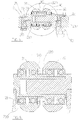
- the guide rail (1) has a loop-wound pathway comprising straight portions (R) and curved portions (C) for connecting the straight portions (R) (see for example figures 1A and 1B ), the guide rail (1) being conformed so as to have an internal rolling wall (11) and an external rolling wall (12) (visible for example in figure 2 in the sectioned part, upper on the left); the carriage (2) being moved (for example via activating means comprising linear motors that are not illustrated) with a movement direction (M) along the loop-wound pathway of the guide rail (1).
- the transport system (S) further comprises a first pair (3) of rollers (31, 32) and a second pair (4) of rollers (41, 42) predisposed on the carriage (2).
- the peculiarities of the transport system (S) of the present invention consist in the fact that it comprises a first shaft (30) mounted and predisposed on the carriage (2) transversally to the movement direction (M) of the carriage (2); and a second shaft (40) also mounted and predisposed on the carriage (2) transversally to the movement direction (M) of the carriage (2); and in that:
- the first shaft (30) on which the rollers (31, 32) of the first pair (3) of rollers are mounted, and the second shaft (40) on which the rollers (41, 42) of the second pair (4) of rollers are mounted, are predisposed on the carriage (2) so as to be pivoted according to an axis perpendicular to the carriage (2), the axis being perpendicular to a plane comprising the first shaft (30) and the second shaft (40), enables the rollers (31, 32) of the first pair (3) of rollers and the rollers (41, 42) of the second pair (4) of rollers to autonomously adapt a position/orientation thereof with respect to the internal wall (11) and the external wall (12) of the second guide rail (1) at the change of direction of the second guide rail (1) in the passage from a straight portion to a curved portion, and vice versa.
- the rollers (31, 32, 41, 42) can, with no force or stress, adapt and change the orientation thereof with respect to the carriage (2) at each change of direction of the guide rail (1), due to the possibility of the first shaft (30) and the second shaft (40) to be pivoted with respect to the carriage (2) according to an axis that is perpendicular to the carriage (2), so that the contact portions (310, 320, 410, 420) of the relative lateral surfaces of the rollers (31, 32, 41, 42) remain always in contact with, and can therefore roll on, the internal wall (11) and external wall (12) of the guide rail (1) independently of the changes of direction of the second guide rail (1).
- the transport system (S) guarantees an excellent stability of the carriage (2) also at each change of direction of the guide rail (1), in the passage from a straight portion to a curved portion, and vice versa, as all the rollers of the two pairs of rollers are always in contact with the internal wall and the external wall of the guide rail.
- rollers are always in contact with the internal and external walls of the guide rail with no force or particular stress, and consequently the degree of wear is particularly contained and reduced with respect to the transport systems of the prior art mentioned in the preamble.
- the contact portions (310, 320, 410, 420) of the lateral surfaces of the rollers (31, 32, 41, 42) with which the rollers (31, 32, 41, 42) are in contact with the internal wall (11) and external wall (12) of the guide rail (1) are conformed as a portion of a spherical cap (see in this regard figure 6 which represents a detail in larger scale and in transversal section of the rollers of the first pair of rollers; this characteristic, though not illustrated in the figures is present, as mentioned, also in the rollers of the second pair of rollers).
- This particular conformation of the contact portions (310, 320, 410, 420) of the lateral surfaces of the rollers (31, 32, 41, 42), is such that the contact between the rollers and the internal wall and external wall of the guide rail occurs on limited and reduced portions of the lateral surfaces of the rollers, further reducing the degree of wear on the rollers, and therefore enabling a greater duration over time.
- the carriage (2) comprises a first through-seating (21) and a second through-seating (22), with a first support element (23) predisposed in the first through-seating (21) so as to be rotatable in said first through-seating (21) according to an axis that is perpendicular to the carriage (2) and a second support element (24) predisposed in the second through-seating (22) so as to be rotatable in said second through-seating (22) according to an axis that is perpendicular to the carriage (2).
- the first shaft (30) is mounted and predisposed on said first support element (23) while the second shaft (40) is mounted and predisposed on the second support element (24).
- the first support element (23) comprises a central housing (230) and two slots (231, 232) arranged on opposite sides of the central housing (230) and communicating with the central housing (230), the central housing (230) having a shape and dimension such as to be able to accommodate and freely receive internally thereof the first pair (3) of rollers (31, 32) so as to enable the rollers (31, 32) to be able to freely rotate about the first shaft (30) and the two slots (231, 232) being arranged and dimensioned so as to be able to receive internally thereof, by form coupling, the ends of the first shaft (30).
- the second support element (24) comprises a central housing (240) and two slots (241, 242) which are arranged on opposite sides of the central housing (240) and are communicating with the central housing (240), the central housing (240) having a shape and dimension such as to be able to accommodate and freely receive internally thereof the second pair (4) of rollers (41, 42) so as to enable the rollers (41, 42) to be able to freely rotate about the second shaft (40) and the two slots (241, 242) being arranged and dimensioned so as to be able to receive internally thereof by form coupling the ends of the second shaft (40).
- the portion of the lateral surface of the rollers (31, 32) of the first pair (3) of rollers opposite the contact portion (310, 320) is advantageously tapered: in this way it is possible to reduce the dimensions of the central housing (230) necessary for internally housing the rollers and, consequently, enabling keeping the volumes modest.
- the portion of the lateral surface of the rollers (41, 42) of the second pair (4) of rollers opposite the contact portion (410, 420) is tapered: in this way it is possible to reduce the dimensions of the central housing (240) necessary for internally housing the rollers.
- the first support element (23) is inserted and predisposed in the first through-seating (21) by interposing of bearings (210) (as for example visible in figure 5 ) so as enable rotation of the first support element (23) in said first through-seating (21) according to an axis that is perpendicular to the carriage (2)
- the second support element (24) is inserted and predisposed in the second through-seating (22) by an interposing of bearings (220) (visible for example in figure 2 ) so as to enable the rotation of the second support element (24) in the second through-seating (22) according to an axis that is perpendicular to the carriage (2).
- a further and other particularly advantageous aspect of the transport system (S) of the present invention consists in the fact that the first support element (23) is inserted and maintained in the first through-seating (21) by first elastic means (81) that are elastically preloaded so as to enable a translation of the first support element (23) with respect to the first through-seating (21) perpendicularly to the guide rail (1) as a consequence of an eventual change of height of the guide rail (1) with respect to a reference plane.
- the second support element (24) is also inserted and maintained in the second through-seating (22) by second elastic means (82) that are elastically preloaded so as to enable a translation of the second support element (24) with respect to the second through-seating (22) perpendicularly to the guide rail (1) as a consequence of an eventual change of height of the guide rail (1) with respect to a reference plane.
- the support elements (23, 24) of the rollers (31, 32, 41, 42) can adjust the vertical position thereof with respect to the carriage (2) so as to maintain the rollers (31, 32) of the first pair (3) of rollers with the relative contact portions (310, 320) always in contact with the internal wall (11) and the external wall (12) of the guide rail (1), and so as to maintain the rollers (41, 42) of the second pair (4) of rollers with the relative contact portions (410, 420) always in contact with the internal wall (11) and the external wall (12) of the guide rail (1).
- the above-mentioned first elastic means (81) comprise: a first plate (83), predisposed and mounted on the carriage (2) on an opposite side with respect to the guide rail (1) at the first through-seating (21) and so as to be able to translate vertically with respect to the carriage (2), a first elastic organ (84) that is elastically preloaded, constrained, at a first end, to the carriage (2) and, at a second end, to the first plate (83), the first support element (23) being predisposed in the first through-seating (21) so that the relative bearings (210) interposed there-between are borne and mounted on the first plate (83) (see for example figures 3A, 3B , 4B , 5 ).
- the above-mentioned second elastic means (82) comprise: a second plate (85), predisposed and mounted on the carriage (2) on an opposite side with respect to the guide rail (1) at the second through-seating (22) and so as to be able to translate vertically with respect to the carriage (2), a second elastic organ (86) that is elastically preloaded, constrained, at a first end, to the carriage (2) and, at a second end, to the second plate (85), the second support element (24) being predisposed in the second through-seating (22) so that the relative bearings (220) interposed there-between are borne and mounted on the second plate (85) (see for example figures 2 , 3B ).
- the guide rail (1) of the transport system (S) can be realised, according to a preferred embodiment illustrated in the figures, so that the internal wall (11) and the external wall (12) are conformed so as to have, at the straight portions (R), a flat surface shape with a same inclination with respect to the axis of the guide rail (1) and, at the curved portions (C), a truncoconical shape.
- Figure 1A illustrates a preferred embodiment of the invention, in which the transport system further comprises: a second loop-wound guide rail (5) having a specular shape to the guide rail (1) and arranged opposite the guide rail (1) (for example below but it could also be arranged above), the second guide rail (5) being conformed so as to have an internal rolling wall (50) and an external rolling wall (51); a second carriage (52) and a connecting element (53), predisposed so as to connect the second carriage (52) to the carriage (2), so that when the carriage (2) is moved along the loop-wound pathway of the guide rail (1), the second carriage (52) is also contemporaneously moved along the loop-wound pathway of the second guide rail (5) in a movement direction (N) parallel to the movement direction (M) of the carriage (2).
- a second loop-wound guide rail (5) having a specular shape to the guide rail (1) and arranged opposite the guide rail (1) (for example below but it could also be arranged above), the second guide rail (5) being conformed so as to have an
- the transport system (S) of the invention further comprises:
- rollers (71, 72) of the third pair (7) of rollers are rotatably mounted on the third shaft (70), flanked to one another and spaced so that a first roller (71) is arranged internally of the second guide rail (5) and has a contact portion (710) of the lateral surface thereof in contact with the internal wall (50) of the second guide rail (5) and can roll on the internal wall (50) when the second carriage (52) is moved in the movement direction (N) and so that a second roller (72) is arranged externally of the guide rail (5) and has a contact portion (720) of the lateral surface thereof in contact with the external wall (51) of the second guide rail (5) and can roll on the external wall (51) when the second carriage (52) is moved in the movement direction (N); the rollers (91, 92) of the fourth pair (9) of rollers are rotatably mounted on the fourth shaft (90), flanked to one another and spaced so that a first roller (91) is arranged internally of the second guide rail (5) and has a contact portion (910) of
- the rollers (71, 72) of the third pair (7) of rollers and the rollers (91, 92) of the fourth pair (9) of rollers can change, with no particular force or stress, adapt and change the orientation thereof with respect to the second carriage (52) at each change of direction of the second guide rail (5), due to the possibility of the third shaft (70) and the fourth shaft (90) to be pivoted with respect to the second carriage (52) according to an axis that is perpendicular to the second carriage (52).
- the rollers (71, 72) of the third pair (7) of rollers and the rollers (91, 92) of the fourth pair (9) of rollers can adapt and change the position thereof with respect to the internal wall (50) and external wall (51) of the guide rail (52) at the change of direction of the second guide rail (52) in the passage from a straight portion to a curved portion, and vice versa, so that the contact portions (710, 720, 910, 920) of the lateral surfaces of the rollers (71, 72, 91, 92) remain always in contact with, and can therefore roll on, the internal wall (50) and external wall (51) independently of the changes of direction of the guide rail (52).
- the above-mentioned connecting element (53) between the carriage (2) and the second carriage (52) comprises coupling means (530) for the coupling and the fixing of a support element for support of a product to be transported (not illustrated).
- the transport system (S) guarantees excellent stability in the transport of the product, as the product, borne by the connecting element (53), is guided and supported in the movement thereof by the two carriages that are moved along the two guide rails, especially at changes of direction of the two guide rails, as in the passages from the straight portions to the curved portions, and vice versa.
- the wear on the rollers is especially modest and contained, which gives them a long working life, surely greater with respect to the prior art systems mentioned in the foregoing.
- the second carriage (52) there will also be two through-seatings in which two support elements are predisposed for the support of the third and fourth shaft, where the rollers and the third and fourth shaft are inserted in housings and slots present in the two support elements, the two support elements being inserted in the through-seatings by the interposing of bearings that enable the shafts to be pivoted according to an axis perpendicular to the carriage.
- the two support elements are inserted in the through-seatings of the second carriage (52) so as not to be able to vary the position thereof vertically in the two through-seatings: this is because the carriage (1) already includes the possibility of height-adjusting the position of the rollers and therefore, during the movement of the two carriages along the loop-wound pathway of the two guide rails, the compensation of any displacements and variations of the reciprocal distance between the two guide rails is carried out by the first elastic means (81) and the second elastic means (82) predisposed on the carriages (2) (the upper carriage).
Landscapes
- Engineering & Computer Science (AREA)
- Mechanical Engineering (AREA)
- Transportation (AREA)
- Bearings For Parts Moving Linearly (AREA)
- Platform Screen Doors And Railroad Systems (AREA)
- Handcart (AREA)
- Electrical Discharge Machining, Electrochemical Machining, And Combined Machining (AREA)
Claims (10)
- Transportsystem (S) zum Transport von Produkten, umfassend:zumindest eine Führungsschiene (1) die einen schleifenförmig geschlossenen Verlauf aufweist und gerade Abschnitte (R) und kurvenförmige Abschnitte (C) zur Verbindung der geraden Abschnitte (R) umfasst, wobei die Führungsschiene (1) derart beschaffen ist, dass sie eine innere Abrollwand (11) und eine äußere Abrollwand (12) aufweist;zumindest einen Wagen (2) zum Transportieren von zumindest einem entsprechenden Produkt, der in einer Bewegungsrichtung (M) entlang dem schleifenförmig geschlossenen Verlauf der Führungsschiene (1) beweglich ist;ein erstes Paar (3) Rollen (31, 32);ein zweites Paar (4) Rollen (41, 42);eine erste Welle (30), die auf dem Wagen (2) quergerichtet zu der Bewegungsrichtung (M) des Wagens (2) montiert und vorgesehen ist;eine zweite Welle (40), die auf dem Wagen (2) quergerichtet zu der Bewegungsrichtung (M) des Wagens (2) montiert und vorgesehen ist;wobei die Rollen (31, 32) des ersten Paares (3) Rollen drehbar auf einer ersten Welle (30) derart nebeneinander und voneinander beabstandet montiert sind, dass eine erste Rolle (31) innerhalb der Führungsschiene (1) angeordnet ist und mit einem Kontaktabschnitt (310) ihrer seitlichen Oberfläche in Berührung mit der inneren Abrollwand (11) der Führungsschiene (1) ist und auf der inneren Abrollwand (11) rollen kann, wenn der Wagen (2) in der Bewegungsrichtung (M) bewegt wird, und dass eine zweite Rolle (32) außerhalb der Führungsschiene (1) angeordnet ist und mit einem Kontaktabschnitt (320) ihrer seitlichen Oberfläche in Berührung mit der äußeren Abrollwand (12) der Führungsschiene (1) ist und auf der äußeren Abrollwand (12) rollen kann, wenn der Wagen (2) in der Bewegungsrichtung (M) bewegt wird;wobei die Rollen (41, 42) des zweiten Paares (4) Rollen drehbar auf einer zweiten Welle (40) derart nebeneinander und voneinander beabstandet montiert sind, dass eine erste Rolle (41) innerhalb der Führungsschiene (1) angeordnet ist und mit einem Kontaktabschnitt (410) ihrer seitlichen Oberfläche in Berührung mit der inneren Abrollwand (11) der Führungsschiene (1) ist und auf der inneren Abrollwand (11) rollen kann, wenn der Wagen (2) in der Bewegungsrichtung (M) bewegt wird, und dass eine zweite Rolle (42) außerhalb der Führungsschiene (1) angeordnet ist und mit einem Kontaktabschnitt (420) ihrer seitlichen Oberfläche in Berührung mit der äußeren Abrollwand (12) der Führungsschiene (1) ist und auf der äußeren Abrollwand (12) rollen kann, wenn der Wagen (2) in der Bewegungsrichtung (M) bewegt wird;dadurch gekennzeichnet, dass die erste Welle (30) und die zweite Welle (40) derart auf dem Wagen (2) vorgesehen und montiert sind, dass sie um eine Achse schwenkbar sind, die orthogonal zu dem Wagen (2) ist, wobei diese Achse orthogonal zu einer Ebene ist, welche die erste Welle (30) und die zweite Welle (40) enthält, um den Rollen (31, 32) des ersten Paares (3) Rollen und den Rollen (41, 42) des zweiten Paares (4) Rollen das Anpassen ihrer Position/Ausrichtung relativ zu der inneren Abrollwand (11) und der äußeren Abrollwand (12) der Führungsschiene (1) beim Richtungswechsel der Führungsschiene (1) im Übergang von einem geraden Abschnitt (R) zu einem kurvenförmigen Abschnitt (C), und umgekehrt, zu ermöglichen, so dass die Kontaktabschnitte (310, 320, 410, 420) der seitlichen Oberflächen der Rollen (31, 32, 41, 42) immer in Berührung mit der inneren Abrollwand (11) und der äußeren Abrollwand (12) bleiben und somit darauf rollen können, unabhängig von den Richtungswechseln der Führungsschiene (1).
- Transportsystem nach Anspruch 1, dadurch gekennzeichnet, dass die Kontaktabschnitte (310, 320, 410, 420) der seitlichen Oberflächen der Rollen (31, 32, 41, 42), mit denen die Rollen (31, 32, 41, 42) in Berührung mit der inneren Abrollwand (11) und der äußeren Abrollwand (12) der Führungsschiene (1) stehen, die Form eines Abschnitts einer kugelförmigen Kappe aufweisen.
- Transportsystem nach einem der vorhergehenden Ansprüche, dadurch gekennzeichnet, dass der Wagen (2) eine erste durchgehende Aufnahme (21) und eine zweite durchgehende Aufnahme (22) umfasst und dadurch, dass es ein erstes Trägerelement (23) umfasst, das in der ersten durchgehenden Aufnahme (21) derart vorgesehen ist, dass es in der ersten durchgehenden Aufnahme (21) um eine Achse drehbar ist, die orthogonal zu dem Wagen (2) ist, und ein zweites Trägerelement (24) umfasst, das in der zweiten durchgehenden Aufnahme (22) derart vorgesehen ist, dass es in der zweiten durchgehenden Aufnahme (22) um eine Achse drehbar ist, die orthogonal zu dem Wagen (2) ist, und dadurch, dass die erste Welle (30) auf dem ersten Trägerelement (23) montiert und vorgesehen ist und die zweite Welle (40) auf dem zweiten Trägerelement (24) montiert und vorgesehen ist.
- Transportsystem nach dem vorhergehenden Anspruch, dadurch gekennzeichnet, dass das erste Trägerelement (23) ein mittleres Gehäuse (230) und zwei Schlitze (231, 232) umfasst, die auf einander gegenüberliegenden Seiten des mittleren Gehäuses (230) angeordnet sind und mit dem mittleren Gehäuse (230) in Verbindung stehen, wobei das mittlere Gehäuse (230) derart geformt und bemessen ist, dass es in seinem Inneren das erste Paar (3) Rollen (31, 32) empfangen und frei aufnehmen kann, so dass sich die Rollen (31, 32) frei um die erste Welle (30) drehen können, und wobei die zwei Schlitze (231, 232) derart angeordnet und bemessen sind, dass sie in ihrem Inneren durch formschlüssige Kupplung die Enden der ersten Welle (30) aufnehmen können, und dadurch, dass das zweite Trägerelement (24) seinerseits ein mittleres Gehäuse (240) und zwei Schlitze (241, 242) umfasst, die auf einander gegenüberliegenden Seiten des mittleren Gehäuses (240) angeordnet sind und mit dem mittleren Gehäuse (240) in Verbindung stehen, wobei das mittlere Gehäuse (240) derart geformt und bemessen ist, dass es in seinem Inneren das zweite Paar (4) Rollen (41, 42) empfangen und frei aufnehmen kann, so dass sich die Rollen (41, 42) frei um die zweite Welle (40) drehen können, und wobei die zwei Schlitze (241, 242) derart angeordnet und bemessen sind, dass sie in ihrem Inneren durch formschlüssige Kupplung die Enden der zweiten Welle (40) aufnehmen können.
- Transportsystem nach einem der Ansprüche 3 und 4, dadurch gekennzeichnet, dass beim Einsetzen und Anordnen des ersten Trägerelements (23) in der ersten durchgehenden Aufnahme (21) Lager (210) zwischengelegt werden, um das Drehen des ersten Trägerelements (23) in der ersten durchgehenden Aufnahme (21) um eine Achse zu ermöglichen, die orthogonal zu dem Wagen (2) ist, und dadurch, dass beim Einsetzen und Anordnen des zweiten Trägerelements (24) in der zweiten durchgehenden Aufnahme (22) Lager (220) zwischengelegt werden, um das Drehen des zweiten Trägerelements (24) in der zweiten durchgehenden Aufnahme (22) um eine Achse zu ermöglichen, die orthogonal zu dem Wagen (2) ist.
- Transportsystem nach dem vorhergehenden Anspruch, dadurch gekennzeichnet, dass das erste Trägerelement (23) in die erste durchgehende Aufnahme (21) mittels erster elastischer Mittel (81) eingeführt und darin festgehalten werden, die elastisch vorgespannt sind, um eine Translationsbewegung des ersten Trägerelements (23) relativ zu der ersten durchgehenden Aufnahme (21) orthogonal zu der Führungsschiene (1) infolge einer eventualen Höhenänderung der Führungsschiene (1) relativ zu einer Bezugsebene zu ermöglichen, um die Rollen (31, 32) des ersten Paares (3) Rollen, die auf dem ersten Trägerelement (23) vorgesehen sind, mit ihren jeweiligen Kontaktabschnitten (310, 320) immer in Berührung mit der inneren Abrollwand (11) und der äußeren Abrollwand (12) der Führungsschiene (1) zu halten, und dadurch, dass das zweite Trägerelement (24) in die zweite durchgehende Aufnahme (22) mittels zweiter elastischer Mittel (82) eingeführt und darin festgehalten werden, die elastisch vorgespannt sind, um eine Translationsbewegung des zweiten Trägerelements (24) relativ zu der zweiten durchgehenden Aufnahme (22) orthogonal zu der Führungsschiene (1) infolge einer eventuellen Höhenänderung der Führungsschiene (1) relativ zu einer Bezugsebene zu ermöglichen, um die Rollen (41, 42) des zweiten Paares (4) Rollen, die auf dem zweiten Trägerelement (24) vorgesehen sind, mit ihren jeweiligen Kontaktabschnitten (410, 420) immer in Berührung mit der inneren Abrollwand (11) und der äußeren Abrollwand (12) der Führungsschiene (1) zu halten.
- Transportsystem nach Anspruch 6, dadurch gekennzeichnet, dass die ersten elastischen Mittel (81) umfassen: eine erste Platte (83), die auf einer relativ zu der Führungsschiene (1) gegenüberliegenden Seite an der ersten durchgehenden Aufnahme (21) auf dem Wagen (2) derart vorgesehen und montiert ist, dass sie relativ zu dem Wagen (2) vertikal eine Translationsbewegung ausführen kann, ein erstes elastisches Organ (84), das elastisch vorgespannt ist und an einem ersten Ende an dem Wagen (2) festgelegt ist und an einem zweiten Ende an der ersten Platte (83) festgelegt ist, wobei das erste Trägerelement (23) in der ersten durchgehenden Aufnahme (21) so vorgesehen ist, dass die entsprechenden zwischengelegten Lager (210) auf der ersten Platte (83) gelagert und montiert sind;
und dadurch, dass die zweiten elastischen Mittel (82) eine zweite Platte (85) umfassen, die auf einer relativ zu der Führungsschiene (1) gegenüberliegenden Seite an der zweiten durchgehende Aufnahme (22) auf dem Wagen (2) derart vorgesehen und montiert ist, dass sie relativ zu dem Wagen (2) vertikal eine Translationsbewegung ausführen kann, ein zweites elastisches Organ (86), das elastisch vorgespannt ist und an einem ersten Ende an dem Wagen (2) festgelegt ist und an einem zweiten Ende an der zweiten Platte (85) festgelegt ist, wobei das zweite Trägerelement (24) in der zweiten durchgehenden Aufnahme (22) so vorgesehen ist, dass die entsprechenden zwischengelegten Lager (220) auf der zweiten Platte (85) gelagert und montiert sind. - Transportsystem nach einem der vorhergehenden Ansprüche, dadurch gekennzeichnet, dass die innere Abrollwand (11) und die äußere Abrollwand (12) der Führungsschiene (1) derart beschaffen sind, dass sie, an den geraden Abschnitten (R), eine Form mit flacher Oberfläche mit derselben Neigung relativ zu der Führungsschiene (1) aufweisen und, an den kurvenförmigen Abschnitten (C), eine kegelstumpfartige Form.
- Transportsystem nach einem der vorhergehenden Ansprüche, dadurch gekennzeichnet, dass es umfasst:eine zweite schleifenförmig geschlossene Führungsschiene (5), die eine zur Führungsschiene (1) spiegelbildliche Form aufweist und gegenüber der Führungsschiene (1) angeordnet ist, wobei die zweite schleifenförmig geschlossene Führungsschiene (5) so beschaffen ist, dass sie eine innere Abrollwand (50) und eine äußere Abrollwand (51) aufweist;einen zweiten Wagen (52);ein Verbindungselement (53), das derart vorgesehen ist, dass es den zweiten Wagen (52) mit dem Wagen (2) verbindet, so dass, wenn der Wagen (2) entlang dem schleifenförmig geschlossenen Verlauf der Führungsschiene (1) bewegt wird, der zweite Wagen (52) ebenfalls gleichzeitig entlang dem schleifenförmig geschlossenen Verlauf der zweiten schleifenförmig geschlossenen Führungsschiene (5) in einer Bewegungsrichtung (N) bewegt wird, die parallel zu der Bewegungsrichtung (M) des Wagens (2) ist;ein drittes Paar (7) Rollen (71, 72);ein viertes Paar (9) Rollen (91, 92);eine dritte Welle (70), die auf dem zweiten Wagen (52) quergerichtet zu der Bewegungsrichtung (N) des zweiten Wagens (52) montiert und vorgesehen ist;eine vierte Welle (90), die auf dem zweiten Wagen (52) quergerichtet zu der Bewegungsrichtung (N) des zweiten Wagens (52) montiert und vorgesehen ist;wobei die Rollen (71, 72) des dritten Paares (7) Rollen drehbar auf der dritten Welle (70) derart nebeneinander und voneinander beabstandet montiert sind, dass eine erste Rolle (71) innerhalb der zweiten Führungsschiene (5) angeordnet ist und mit einem Kontaktabschnitt (710) ihrer seitlichen Oberfläche in Berührung mit der inneren Abrollwand (50) der zweiten schleifenförmig geschlossenen Führungsschiene (5) ist und auf der inneren Abrollwand (50) rollen kann, wenn der zweite Wagen (52) in der Bewegungsrichtung (N) bewegt wird, und dass eine zweite Rolle (72) außerhalb der zweiten Führungsschiene (5) angeordnet ist und mit einem Kontaktabschnitt (720) ihrer seitlichen Oberfläche in Berührung mit der äußeren Abrollwand (51) der zweiten schleifenförmig geschlossenen Führungsschiene (5) ist und auf der äußeren Abrollwand (51) rollen kann, wenn der zweite Wagen (52) in der Bewegungsrichtung (N) bewegt wird;wobei die Rollen (91, 92) des vierten Paares (9) Rollen drehbar auf der vierten Welle (90) derart nebeneinander und voneinander beabstandet montiert sind, dass eine erste Rolle (91) innerhalb der zweiten schleifenförmig geschlossenen Führungsschiene (5) angeordnet ist und mit einem Kontaktabschnitt (910) ihrer seitlichen Oberfläche in Berührung mit der inneren Abrollwand (50) der zweiten Führungsschiene (5) ist und auf der inneren Abrollwand (50) rollen kann, wenn der zweite Wagen (52) in der Bewegungsrichtung (N) bewegt wird, und dass eine zweite Rolle (92) außerhalb der zweiten schleifenförmig geschlossenen Führungsschiene (5) angeordnet ist und mit einem Kontaktabschnitt (920) ihrer seitlichen Oberfläche in Berührung mit der äußeren Abrollwand (51) der zweiten schleifenförmig geschlossenen Führungsschiene (5) ist und auf der äußeren Abrollwand (51) rollen kann, wenn der zweite Wagen (52) in der Bewegungsrichtung (N) bewegt wird;wobei die dritte Welle (70) und die vierte Welle (90) derart auf dem zweiten Wagen (52) vorgesehen und montiert sind, dass sie um eine Achse schwenkbar sind, die orthogonal zu dem zweiten Wagen (52) ist, wobei diese Achse orthogonal zu einer Ebene ist, welche die dritte Welle (70) und die vierte Welle (90) enthält, um den Rollen (71, 72) des dritten Paares (7) Rollen und den Rollen (91, 92) des vierten Paares (9) Rollen das Anpassen ihrer Position/Ausrichtung relativ zu der inneren Abrollwand (50) und der äußeren Abrollwand (51) der zweiten schleifenförmig geschlossenen Führungsschiene (5) beim Richtungswechsel der zweiten schleifenförmig geschlossenen Führungsschiene (5) im Übergang von einem geraden Abschnitt zu einem kurvenförmigen Abschnitt, und umgekehrt, zu ermöglichen, so dass die Kontaktabschnitte (710, 720, 910, 920) der seitlichen Oberflächen der Rollen (71, 72, 91, 92) immer in Berührung mit der inneren Abrollwand (50) und der äußeren Abrollwand (51) bleiben und somit darauf rollen können, unabhängig von den Richtungswechseln der zweiten schleifenförmig geschlossenen Führungsschiene (5).
- Transportsystem nach dem vorhergehenden Anspruch, dadurch gekennzeichnet, dass das Verbindungselement (53) Kupplungsmittel (530) zur Ankopplung und Befestigung eines Trägerelements zum Tragen eines zu transportierenden Produktes umfasst.
Applications Claiming Priority (2)
| Application Number | Priority Date | Filing Date | Title |
|---|---|---|---|
| IT102016000097555A IT201600097555A1 (it) | 2016-09-29 | 2016-09-29 | Sistema di trasporto per il trasporto di prodotti |
| PCT/IB2017/055905 WO2018060882A1 (en) | 2016-09-29 | 2017-09-27 | Transporting system for transporting products |
Publications (2)
| Publication Number | Publication Date |
|---|---|
| EP3519331A1 EP3519331A1 (de) | 2019-08-07 |
| EP3519331B1 true EP3519331B1 (de) | 2020-11-04 |
Family
ID=57960628
Family Applications (1)
| Application Number | Title | Priority Date | Filing Date |
|---|---|---|---|
| EP17793727.3A Not-in-force EP3519331B1 (de) | 2016-09-29 | 2017-09-27 | Transportsystem zum transport von produkten |
Country Status (7)
| Country | Link |
|---|---|
| US (1) | US11046524B2 (de) |
| EP (1) | EP3519331B1 (de) |
| KR (1) | KR102435484B1 (de) |
| CN (1) | CN109789975B (de) |
| ES (1) | ES2846074T3 (de) |
| IT (1) | IT201600097555A1 (de) |
| WO (1) | WO2018060882A1 (de) |
Families Citing this family (1)
| Publication number | Priority date | Publication date | Assignee | Title |
|---|---|---|---|---|
| IT201800007365A1 (it) * | 2018-07-20 | 2020-01-20 | Sistema di trasporto per il trasporto di prodotti |
Family Cites Families (32)
| Publication number | Priority date | Publication date | Assignee | Title |
|---|---|---|---|---|
| US1312417A (en) * | 1919-08-05 | Planodraph c | ||
| GB347409A (en) * | 1930-03-14 | 1931-04-30 | Huebsch Mfg Company | Improvements in conveyor trolleys or runners |
| US2932258A (en) * | 1955-08-16 | 1960-04-12 | Alweg Forschung Gmbh | Railway systems |
| GB813769A (en) * | 1956-02-27 | 1959-05-21 | Roger Blanc | Improvements in or relating to chain conveyors |
| US3525306A (en) * | 1967-12-21 | 1970-08-25 | Common Market Trading Corp Ltd | Suspended railway |
| CH537826A (de) * | 1972-02-28 | 1973-07-31 | Hero Foerdertechnik Gmbh U Co | Hängeförderanlage |
| SU1076378A1 (ru) * | 1982-02-19 | 1984-02-29 | Брянский Ордена "Знак Почета" Институт Транспортного Машиностроения | Каретка подвесного конвейера |
| US5086705A (en) * | 1990-02-26 | 1992-02-11 | Bernard Jarvis | Linear positioning system |
| US5445080A (en) * | 1993-10-21 | 1995-08-29 | Austin; Robert | Free ranging monotrack sortveyor with selectively lockable article carrying tilt tray |
| DE19514353A1 (de) * | 1995-04-18 | 1996-10-24 | Rolf W Zierdt | In Kurven spielfreies Laufrollenführungssystem |
| JPH11208859A (ja) * | 1998-01-26 | 1999-08-03 | Nobuyuki Tsuboi | 搬送システム |
| US7086525B2 (en) * | 1999-09-23 | 2006-08-08 | Stewart Systems, Inc. | Conveyor for continuous proofing and baking apparatus |
| KR20040052485A (ko) * | 2001-03-01 | 2004-06-23 | 케스케이드 엔지니어링 인코퍼레이티드 | 개별 운송 시스템 |
| JP3782798B2 (ja) * | 2003-07-07 | 2006-06-07 | 泉陽機工株式会社 | モノレール装置 |
| US7997404B2 (en) * | 2006-11-03 | 2011-08-16 | Habasit Ag | Conveyor belt with intermodular supported spheres |
| WO2010065612A1 (en) * | 2008-12-02 | 2010-06-10 | Frost Links, Inc. | Adjustable height trolley assembly |
| CN102427984B (zh) * | 2009-06-02 | 2015-05-13 | 横梁道路公司 | 用于悬挂交通工具的轨道和转向架 |
| CA2708885C (en) * | 2009-10-16 | 2011-10-04 | Peter Edward Timan | A monorail bogie having a traction/pitching control assembly |
| GB201200888D0 (en) * | 2012-01-19 | 2012-02-29 | Hepco Slide Systems Ltd | Track systems |
| DE102012103378A1 (de) * | 2012-04-18 | 2013-10-24 | Uhlmann Pac-Systeme Gmbh & Co Kg | Transportvorrichtung mit Linearmotorantrieb |
| KR20130128882A (ko) * | 2012-05-18 | 2013-11-27 | 주식회사 우성 | 홀 통로 자동용접용 캐리지장치 |
| TW201418125A (zh) * | 2012-09-19 | 2014-05-16 | Singapore Machinery Co Pte Ltd | 用於單位生產系統的推進器總成及導軌 |
| DE102012018828A1 (de) * | 2012-09-25 | 2014-03-27 | Heidelberger Druckmaschinen Ag | Klebebinder |
| ES2534254B1 (es) * | 2013-07-25 | 2016-01-26 | Thyssenkrupp Elevator Innovation Center, S. A. | Cadena de seguridad para paletas de pasillos para el transporte de personas y mercancías |
| CN103523667A (zh) * | 2013-10-27 | 2014-01-22 | 黑龙江宏宇电站设备有限公司 | 矿用钢丝绳牵引单轨吊车运输系统及其运输方法 |
| KR101443194B1 (ko) * | 2014-04-15 | 2014-09-22 | 신승춘 | 롤 거치대 |
| SE538292C2 (sv) * | 2014-12-18 | 2016-04-26 | Il Granito Ab | Track, load carrying carriage and track system |
| CH712095A1 (de) * | 2016-02-04 | 2017-08-15 | Ferag Ag | Laufwagen für ein Fördersystem und Fördersystem mit Laufwagen. |
| CN105818819B (zh) * | 2016-03-31 | 2018-03-09 | 北京航天控制仪器研究所 | 一种双闭合磁路弯道电磁变轨导向装置及方法 |
| CH712786A1 (de) * | 2016-08-02 | 2018-02-15 | Ferag Ag | Fördersystem zum Fördern von Fördergütern, mit einer Mitnehmerkette mit mindestens einem Mitnehmer zum Mitnehmen eines Förderwagens. |
| WO2019009105A1 (ja) * | 2017-07-05 | 2019-01-10 | 日本トムソン株式会社 | テーブル循環案内装置 |
| US11059498B2 (en) * | 2018-06-08 | 2021-07-13 | Castree Projects Limited | Trolley |
-
2016
- 2016-09-29 IT IT102016000097555A patent/IT201600097555A1/it unknown
-
2017
- 2017-09-27 ES ES17793727T patent/ES2846074T3/es active Active
- 2017-09-27 KR KR1020197011498A patent/KR102435484B1/ko active Active
- 2017-09-27 CN CN201780058211.2A patent/CN109789975B/zh not_active Expired - Fee Related
- 2017-09-27 US US16/329,580 patent/US11046524B2/en active Active
- 2017-09-27 WO PCT/IB2017/055905 patent/WO2018060882A1/en not_active Ceased
- 2017-09-27 EP EP17793727.3A patent/EP3519331B1/de not_active Not-in-force
Non-Patent Citations (1)
| Title |
|---|
| None * |
Also Published As
| Publication number | Publication date |
|---|---|
| WO2018060882A1 (en) | 2018-04-05 |
| EP3519331A1 (de) | 2019-08-07 |
| CN109789975A (zh) | 2019-05-21 |
| IT201600097555A1 (it) | 2018-03-29 |
| KR102435484B1 (ko) | 2022-08-22 |
| KR20190053930A (ko) | 2019-05-20 |
| ES2846074T3 (es) | 2021-07-28 |
| CN109789975B (zh) | 2021-03-23 |
| US11046524B2 (en) | 2021-06-29 |
| US20190210810A1 (en) | 2019-07-11 |
Similar Documents
| Publication | Publication Date | Title |
|---|---|---|
| US20190218038A1 (en) | A transport system | |
| US20110042183A1 (en) | support device for a conveyor installation and method for operation of a conveyor installation | |
| EP3768620B1 (de) | Transportsystem | |
| CN109436694B (zh) | 智能柔性封边线进料系统 | |
| US10399622B2 (en) | Conveying apparatus for conveying transporting structures | |
| US11046524B2 (en) | Transporting system for transporting products | |
| AU2007280673B2 (en) | Apparatus for producing and/or processing panels | |
| US6612229B2 (en) | Multistation press | |
| EP2826736B1 (de) | Vorrichtung zum be- und entladen von keramischen produkten in oder aus einer speicherbox mit rollen | |
| EP3823919B1 (de) | Transportsystem mit einem mobilen wagen zum transport von produkten entlang einer führungsbahn | |
| CN220264286U (zh) | 一种输送变道装置 | |
| EP2325115A1 (de) | Schnell schwenkende Strömungsablenkungseinheit | |
| EP3233605A1 (de) | Schiene, lasttragender wagen und schienensystem | |
| CN223015570U (zh) | 一种载具定位机构和自动运输线 | |
| CN208022249U (zh) | 辊台 | |
| CN221318108U (zh) | 一种五金钢板加工用的夹送机 | |
| CN218055818U (zh) | 一种自动捆绑机用送料装置 | |
| CN216943164U (zh) | 物流台车 | |
| CN219296319U (zh) | 一种pcb板输送机构 | |
| CN223495540U (zh) | 一种物料转向输送装置 | |
| PL185183B1 (pl) | Maszyna do bocznego wyrównywania wyrobów cegielnianych i ogniotrwałych, zwłaszcza do kalibrowania kształtek budowlanych | |
| CN110626730A (zh) | 自动传输装置 | |
| SU1050991A1 (ru) | Роликоопора рольганга | |
| CN114455247A (zh) | 一种型材加工系统 | |
| DE102009053886B4 (de) | Umlenkeinrichtung und Werkstückträgerfördersystem |
Legal Events
| Date | Code | Title | Description |
|---|---|---|---|
| STAA | Information on the status of an ep patent application or granted ep patent |
Free format text: STATUS: UNKNOWN |
|
| STAA | Information on the status of an ep patent application or granted ep patent |
Free format text: STATUS: THE INTERNATIONAL PUBLICATION HAS BEEN MADE |
|
| PUAI | Public reference made under article 153(3) epc to a published international application that has entered the european phase |
Free format text: ORIGINAL CODE: 0009012 |
|
| STAA | Information on the status of an ep patent application or granted ep patent |
Free format text: STATUS: REQUEST FOR EXAMINATION WAS MADE |
|
| 17P | Request for examination filed |
Effective date: 20190423 |
|
| AK | Designated contracting states |
Kind code of ref document: A1 Designated state(s): AL AT BE BG CH CY CZ DE DK EE ES FI FR GB GR HR HU IE IS IT LI LT LU LV MC MK MT NL NO PL PT RO RS SE SI SK SM TR |
|
| AX | Request for extension of the european patent |
Extension state: BA ME |
|
| DAV | Request for validation of the european patent (deleted) | ||
| DAX | Request for extension of the european patent (deleted) | ||
| GRAP | Despatch of communication of intention to grant a patent |
Free format text: ORIGINAL CODE: EPIDOSNIGR1 |
|
| STAA | Information on the status of an ep patent application or granted ep patent |
Free format text: STATUS: GRANT OF PATENT IS INTENDED |
|
| INTG | Intention to grant announced |
Effective date: 20200630 |
|
| GRAS | Grant fee paid |
Free format text: ORIGINAL CODE: EPIDOSNIGR3 |
|
| GRAA | (expected) grant |
Free format text: ORIGINAL CODE: 0009210 |
|
| STAA | Information on the status of an ep patent application or granted ep patent |
Free format text: STATUS: THE PATENT HAS BEEN GRANTED |
|
| AK | Designated contracting states |
Kind code of ref document: B1 Designated state(s): AL AT BE BG CH CY CZ DE DK EE ES FI FR GB GR HR HU IE IS IT LI LT LU LV MC MK MT NL NO PL PT RO RS SE SI SK SM TR |
|
| REG | Reference to a national code |
Ref country code: GB Ref legal event code: FG4D |
|
| REG | Reference to a national code |
Ref country code: CH Ref legal event code: EP |
|
| REG | Reference to a national code |
Ref country code: AT Ref legal event code: REF Ref document number: 1330566 Country of ref document: AT Kind code of ref document: T Effective date: 20201115 |
|
| REG | Reference to a national code |
Ref country code: IE Ref legal event code: FG4D |
|
| REG | Reference to a national code |
Ref country code: DE Ref legal event code: R096 Ref document number: 602017027019 Country of ref document: DE |
|
| REG | Reference to a national code |
Ref country code: NL Ref legal event code: MP Effective date: 20201104 |
|
| REG | Reference to a national code |
Ref country code: AT Ref legal event code: MK05 Ref document number: 1330566 Country of ref document: AT Kind code of ref document: T Effective date: 20201104 |
|
| PG25 | Lapsed in a contracting state [announced via postgrant information from national office to epo] |
Ref country code: NO Free format text: LAPSE BECAUSE OF FAILURE TO SUBMIT A TRANSLATION OF THE DESCRIPTION OR TO PAY THE FEE WITHIN THE PRESCRIBED TIME-LIMIT Effective date: 20210204 Ref country code: GR Free format text: LAPSE BECAUSE OF FAILURE TO SUBMIT A TRANSLATION OF THE DESCRIPTION OR TO PAY THE FEE WITHIN THE PRESCRIBED TIME-LIMIT Effective date: 20210205 Ref country code: FI Free format text: LAPSE BECAUSE OF FAILURE TO SUBMIT A TRANSLATION OF THE DESCRIPTION OR TO PAY THE FEE WITHIN THE PRESCRIBED TIME-LIMIT Effective date: 20201104 Ref country code: RS Free format text: LAPSE BECAUSE OF FAILURE TO SUBMIT A TRANSLATION OF THE DESCRIPTION OR TO PAY THE FEE WITHIN THE PRESCRIBED TIME-LIMIT Effective date: 20201104 Ref country code: PT Free format text: LAPSE BECAUSE OF FAILURE TO SUBMIT A TRANSLATION OF THE DESCRIPTION OR TO PAY THE FEE WITHIN THE PRESCRIBED TIME-LIMIT Effective date: 20210304 |
|
| PG25 | Lapsed in a contracting state [announced via postgrant information from national office to epo] |
Ref country code: AT Free format text: LAPSE BECAUSE OF FAILURE TO SUBMIT A TRANSLATION OF THE DESCRIPTION OR TO PAY THE FEE WITHIN THE PRESCRIBED TIME-LIMIT Effective date: 20201104 Ref country code: IS Free format text: LAPSE BECAUSE OF FAILURE TO SUBMIT A TRANSLATION OF THE DESCRIPTION OR TO PAY THE FEE WITHIN THE PRESCRIBED TIME-LIMIT Effective date: 20210304 Ref country code: LV Free format text: LAPSE BECAUSE OF FAILURE TO SUBMIT A TRANSLATION OF THE DESCRIPTION OR TO PAY THE FEE WITHIN THE PRESCRIBED TIME-LIMIT Effective date: 20201104 Ref country code: PL Free format text: LAPSE BECAUSE OF FAILURE TO SUBMIT A TRANSLATION OF THE DESCRIPTION OR TO PAY THE FEE WITHIN THE PRESCRIBED TIME-LIMIT Effective date: 20201104 Ref country code: SE Free format text: LAPSE BECAUSE OF FAILURE TO SUBMIT A TRANSLATION OF THE DESCRIPTION OR TO PAY THE FEE WITHIN THE PRESCRIBED TIME-LIMIT Effective date: 20201104 Ref country code: BG Free format text: LAPSE BECAUSE OF FAILURE TO SUBMIT A TRANSLATION OF THE DESCRIPTION OR TO PAY THE FEE WITHIN THE PRESCRIBED TIME-LIMIT Effective date: 20210204 |
|
| REG | Reference to a national code |
Ref country code: LT Ref legal event code: MG9D |
|
| PG25 | Lapsed in a contracting state [announced via postgrant information from national office to epo] |
Ref country code: HR Free format text: LAPSE BECAUSE OF FAILURE TO SUBMIT A TRANSLATION OF THE DESCRIPTION OR TO PAY THE FEE WITHIN THE PRESCRIBED TIME-LIMIT Effective date: 20201104 |
|
| REG | Reference to a national code |
Ref country code: ES Ref legal event code: FG2A Ref document number: 2846074 Country of ref document: ES Kind code of ref document: T3 Effective date: 20210728 |
|
| PG25 | Lapsed in a contracting state [announced via postgrant information from national office to epo] |
Ref country code: RO Free format text: LAPSE BECAUSE OF FAILURE TO SUBMIT A TRANSLATION OF THE DESCRIPTION OR TO PAY THE FEE WITHIN THE PRESCRIBED TIME-LIMIT Effective date: 20201104 Ref country code: SK Free format text: LAPSE BECAUSE OF FAILURE TO SUBMIT A TRANSLATION OF THE DESCRIPTION OR TO PAY THE FEE WITHIN THE PRESCRIBED TIME-LIMIT Effective date: 20201104 Ref country code: LT Free format text: LAPSE BECAUSE OF FAILURE TO SUBMIT A TRANSLATION OF THE DESCRIPTION OR TO PAY THE FEE WITHIN THE PRESCRIBED TIME-LIMIT Effective date: 20201104 Ref country code: EE Free format text: LAPSE BECAUSE OF FAILURE TO SUBMIT A TRANSLATION OF THE DESCRIPTION OR TO PAY THE FEE WITHIN THE PRESCRIBED TIME-LIMIT Effective date: 20201104 Ref country code: CZ Free format text: LAPSE BECAUSE OF FAILURE TO SUBMIT A TRANSLATION OF THE DESCRIPTION OR TO PAY THE FEE WITHIN THE PRESCRIBED TIME-LIMIT Effective date: 20201104 Ref country code: SM Free format text: LAPSE BECAUSE OF FAILURE TO SUBMIT A TRANSLATION OF THE DESCRIPTION OR TO PAY THE FEE WITHIN THE PRESCRIBED TIME-LIMIT Effective date: 20201104 |
|
| REG | Reference to a national code |
Ref country code: DE Ref legal event code: R097 Ref document number: 602017027019 Country of ref document: DE |
|
| PG25 | Lapsed in a contracting state [announced via postgrant information from national office to epo] |
Ref country code: DK Free format text: LAPSE BECAUSE OF FAILURE TO SUBMIT A TRANSLATION OF THE DESCRIPTION OR TO PAY THE FEE WITHIN THE PRESCRIBED TIME-LIMIT Effective date: 20201104 |
|
| PLBE | No opposition filed within time limit |
Free format text: ORIGINAL CODE: 0009261 |
|
| STAA | Information on the status of an ep patent application or granted ep patent |
Free format text: STATUS: NO OPPOSITION FILED WITHIN TIME LIMIT |
|
| 26N | No opposition filed |
Effective date: 20210805 |
|
| PG25 | Lapsed in a contracting state [announced via postgrant information from national office to epo] |
Ref country code: AL Free format text: LAPSE BECAUSE OF FAILURE TO SUBMIT A TRANSLATION OF THE DESCRIPTION OR TO PAY THE FEE WITHIN THE PRESCRIBED TIME-LIMIT Effective date: 20201104 Ref country code: NL Free format text: LAPSE BECAUSE OF FAILURE TO SUBMIT A TRANSLATION OF THE DESCRIPTION OR TO PAY THE FEE WITHIN THE PRESCRIBED TIME-LIMIT Effective date: 20201104 |
|
| PGFP | Annual fee paid to national office [announced via postgrant information from national office to epo] |
Ref country code: FR Payment date: 20210923 Year of fee payment: 5 Ref country code: IT Payment date: 20210929 Year of fee payment: 5 |
|
| PG25 | Lapsed in a contracting state [announced via postgrant information from national office to epo] |
Ref country code: SI Free format text: LAPSE BECAUSE OF FAILURE TO SUBMIT A TRANSLATION OF THE DESCRIPTION OR TO PAY THE FEE WITHIN THE PRESCRIBED TIME-LIMIT Effective date: 20201104 |
|
| PGFP | Annual fee paid to national office [announced via postgrant information from national office to epo] |
Ref country code: DE Payment date: 20211008 Year of fee payment: 5 Ref country code: ES Payment date: 20211007 Year of fee payment: 5 |
|
| REG | Reference to a national code |
Ref country code: CH Ref legal event code: PL |
|
| REG | Reference to a national code |
Ref country code: BE Ref legal event code: MM Effective date: 20210930 |
|
| GBPC | Gb: european patent ceased through non-payment of renewal fee |
Effective date: 20210927 |
|
| PG25 | Lapsed in a contracting state [announced via postgrant information from national office to epo] |
Ref country code: IS Free format text: LAPSE BECAUSE OF FAILURE TO SUBMIT A TRANSLATION OF THE DESCRIPTION OR TO PAY THE FEE WITHIN THE PRESCRIBED TIME-LIMIT Effective date: 20210304 Ref country code: MC Free format text: LAPSE BECAUSE OF FAILURE TO SUBMIT A TRANSLATION OF THE DESCRIPTION OR TO PAY THE FEE WITHIN THE PRESCRIBED TIME-LIMIT Effective date: 20201104 |
|
| PG25 | Lapsed in a contracting state [announced via postgrant information from national office to epo] |
Ref country code: LU Free format text: LAPSE BECAUSE OF NON-PAYMENT OF DUE FEES Effective date: 20210927 Ref country code: IE Free format text: LAPSE BECAUSE OF NON-PAYMENT OF DUE FEES Effective date: 20210927 Ref country code: GB Free format text: LAPSE BECAUSE OF NON-PAYMENT OF DUE FEES Effective date: 20210927 Ref country code: BE Free format text: LAPSE BECAUSE OF NON-PAYMENT OF DUE FEES Effective date: 20210930 |
|
| PG25 | Lapsed in a contracting state [announced via postgrant information from national office to epo] |
Ref country code: LI Free format text: LAPSE BECAUSE OF NON-PAYMENT OF DUE FEES Effective date: 20210930 Ref country code: CH Free format text: LAPSE BECAUSE OF NON-PAYMENT OF DUE FEES Effective date: 20210930 |
|
| REG | Reference to a national code |
Ref country code: DE Ref legal event code: R119 Ref document number: 602017027019 Country of ref document: DE |
|
| P01 | Opt-out of the competence of the unified patent court (upc) registered |
Effective date: 20230419 |
|
| PG25 | Lapsed in a contracting state [announced via postgrant information from national office to epo] |
Ref country code: CY Free format text: LAPSE BECAUSE OF FAILURE TO SUBMIT A TRANSLATION OF THE DESCRIPTION OR TO PAY THE FEE WITHIN THE PRESCRIBED TIME-LIMIT Effective date: 20201104 |
|
| PG25 | Lapsed in a contracting state [announced via postgrant information from national office to epo] |
Ref country code: HU Free format text: LAPSE BECAUSE OF FAILURE TO SUBMIT A TRANSLATION OF THE DESCRIPTION OR TO PAY THE FEE WITHIN THE PRESCRIBED TIME-LIMIT; INVALID AB INITIO Effective date: 20170927 Ref country code: FR Free format text: LAPSE BECAUSE OF NON-PAYMENT OF DUE FEES Effective date: 20220930 Ref country code: DE Free format text: LAPSE BECAUSE OF NON-PAYMENT OF DUE FEES Effective date: 20230401 |
|
| REG | Reference to a national code |
Ref country code: ES Ref legal event code: FD2A Effective date: 20231030 |
|
| PG25 | Lapsed in a contracting state [announced via postgrant information from national office to epo] |
Ref country code: IT Free format text: LAPSE BECAUSE OF NON-PAYMENT OF DUE FEES Effective date: 20220927 |
|
| PG25 | Lapsed in a contracting state [announced via postgrant information from national office to epo] |
Ref country code: ES Free format text: LAPSE BECAUSE OF NON-PAYMENT OF DUE FEES Effective date: 20220928 |
|
| PG25 | Lapsed in a contracting state [announced via postgrant information from national office to epo] |
Ref country code: ES Free format text: LAPSE BECAUSE OF NON-PAYMENT OF DUE FEES Effective date: 20220928 |
|
| PG25 | Lapsed in a contracting state [announced via postgrant information from national office to epo] |
Ref country code: MK Free format text: LAPSE BECAUSE OF FAILURE TO SUBMIT A TRANSLATION OF THE DESCRIPTION OR TO PAY THE FEE WITHIN THE PRESCRIBED TIME-LIMIT Effective date: 20201104 |
|
| PG25 | Lapsed in a contracting state [announced via postgrant information from national office to epo] |
Ref country code: TR Free format text: LAPSE BECAUSE OF FAILURE TO SUBMIT A TRANSLATION OF THE DESCRIPTION OR TO PAY THE FEE WITHIN THE PRESCRIBED TIME-LIMIT Effective date: 20201104 |
|
| PG25 | Lapsed in a contracting state [announced via postgrant information from national office to epo] |
Ref country code: MT Free format text: LAPSE BECAUSE OF FAILURE TO SUBMIT A TRANSLATION OF THE DESCRIPTION OR TO PAY THE FEE WITHIN THE PRESCRIBED TIME-LIMIT Effective date: 20201104 |