EP3517009A1 - Ensemble formant abattant pour toilettes et toilettes dotées de dispositif de verrouillage - Google Patents
Ensemble formant abattant pour toilettes et toilettes dotées de dispositif de verrouillage Download PDFInfo
- Publication number
- EP3517009A1 EP3517009A1 EP18153802.6A EP18153802A EP3517009A1 EP 3517009 A1 EP3517009 A1 EP 3517009A1 EP 18153802 A EP18153802 A EP 18153802A EP 3517009 A1 EP3517009 A1 EP 3517009A1
- Authority
- EP
- European Patent Office
- Prior art keywords
- cover
- locking
- toilet
- seat
- seat part
- Prior art date
- Legal status (The legal status is an assumption and is not a legal conclusion. Google has not performed a legal analysis and makes no representation as to the accuracy of the status listed.)
- Granted
Links
- XLYOFNOQVPJJNP-UHFFFAOYSA-N water Substances O XLYOFNOQVPJJNP-UHFFFAOYSA-N 0.000 title description 2
- 230000005540 biological transmission Effects 0.000 claims description 5
- 238000013016 damping Methods 0.000 claims description 5
- 239000000919 ceramic Substances 0.000 description 5
- 238000004140 cleaning Methods 0.000 description 3
- 238000010276 construction Methods 0.000 description 2
- 230000008878 coupling Effects 0.000 description 2
- 238000010168 coupling process Methods 0.000 description 2
- 238000005859 coupling reaction Methods 0.000 description 2
- 230000003993 interaction Effects 0.000 description 2
- 230000006835 compression Effects 0.000 description 1
- 238000007906 compression Methods 0.000 description 1
- 238000006073 displacement reaction Methods 0.000 description 1
- 230000002349 favourable effect Effects 0.000 description 1
- 230000012447 hatching Effects 0.000 description 1
- 238000003780 insertion Methods 0.000 description 1
- 230000037431 insertion Effects 0.000 description 1
- 230000010354 integration Effects 0.000 description 1
- 230000013011 mating Effects 0.000 description 1
- 239000000725 suspension Substances 0.000 description 1
Images
Classifications
-
- A—HUMAN NECESSITIES
- A47—FURNITURE; DOMESTIC ARTICLES OR APPLIANCES; COFFEE MILLS; SPICE MILLS; SUCTION CLEANERS IN GENERAL
- A47K—SANITARY EQUIPMENT NOT OTHERWISE PROVIDED FOR; TOILET ACCESSORIES
- A47K13/00—Seats or covers for all kinds of closets
- A47K13/24—Parts or details not covered in, or of interest apart from, groups A47K13/02 - A47K13/22, e.g. devices imparting a swinging or vibrating motion to the seats
- A47K13/26—Mounting devices for seats or covers
-
- A—HUMAN NECESSITIES
- A47—FURNITURE; DOMESTIC ARTICLES OR APPLIANCES; COFFEE MILLS; SPICE MILLS; SUCTION CLEANERS IN GENERAL
- A47K—SANITARY EQUIPMENT NOT OTHERWISE PROVIDED FOR; TOILET ACCESSORIES
- A47K13/00—Seats or covers for all kinds of closets
- A47K13/12—Hinges
Definitions
- the present invention relates to a toilet set for a toilet.
- Toilets water closets
- a toilet body often made of ceramic
- a toilet seat and a lid are provided.
- the toilet seat allows the user to sit on it and can be folded up regularly around an axis transverse to the rear of the toilet.
- a likewise usually provided toilet lid for closing the toilet bowl which usually also covers the seat with.
- WCs have to be cleaned very frequently and thoroughly, and cleaning with regard to their functional properties is an essential aspect. This also affects the toilet seat and the toilet lid. Accordingly, it is generally known to provide fastening devices with which these parts can be reduced in a simplified manner from the toilet body. "Simplified” means that, for example, the loosening of screw connections, with which hinge parts are mounted through vertical holes in the toilet body, is too cumbersome for regular cleaning and cleaning personnel and consequently no dismantling is required.
- Analog shows the DE 10 2006 020 205 A1 as much younger document a variant with matching axis of rotation of the lid and seat and an operating option behind and outside the lid on both sides.
- the cover with the seat can also be removed there.
- a sleeve with a helical ramp provided therein is responsible for releasing the lid and seat from the toilet body as a result of being flipped up.
- the ramp moves a spring, which releases a locking engagement with a fixing pin on the toilet body.
- the EP 2 679 127 A1 shows a solution in which the folding also opens a positive connection and thus cover and seat can be removed.
- the invention has for its object to provide a toilet cover set and a toilet with further improved performance characteristics.
- a toilet cover set for mounting on a toilet body with a toilet bowl, which has flat cover: a cover part for covering the toilet bowl, a seat part as a seat for a user and a locking device for locking the seat part or the cover part with a further part of the flat clothing, at least one fastening element for fixing the flat clothing on the WC body, which is designed to be fastened on the WC body and then allow the flat clothing to be fastened to the at least one fastening element, wherein the flat set is adapted to automatically actuate the locking means by attaching the flat garniture to the fastener and releasing it, and by an appropriately equipped WC.
- a basic idea of the invention is to use the attachment of an existing at least from the lid part and the seat part cover set on the toilet body in addition to the automatic actuation of the locking device. In other words, by removing the cover assembly from the toilet body unlocking and locking by a fixture instead.
- the flat cover consists of the cover part and the seat part and has no further mounting part for mounting on the fastening element
- the locking part relates to the seat part and cover part. Consequently, these two parts are also detachable from each other after assembly of the fastener, while they are locked together in the mounted state on the fastener.
- this flat fitting may also have a mounting part, wherein the locking by the locking device then may also affect the relationship between this mounting part and the seat part or the cover part (or between all three parts).
- the invention requires no further actuators to operate the locking device and no additional handles.
- the removal (and the necessary actions) will do the unlocking at the same time.
- the invention thus offers a particularly simple operation and with regard to the exterior design of the parts involved also the possibility of a particularly simple design.
- the mentioned fastener is usually provided at least twice, because typically two attachment points are present on a toilet body, for example.
- Vertical openings through a toilet ceramic through, in each case a fastener, the opening can be screwed enforcing.
- the fastener can then each z. B. have a pin for placing the flat sheet set thereon.
- a possible and favorable embodiment provides the part of the cover set a receptacle for the (at least one) fastener before, in many practical cases, two receptacles for each one fastener.
- the flat fitting is made by placing and thereby inserting the (respective) fastener secured in the receptacle and removed by a reverse movement.
- the holder in the attached state can be done in different ways, such as a snap mechanism, a magnetic force, etc.
- the fastening of the flat clothing is usually associated with a vertical movement, which can be used according to the invention.
- a device for translating this vertical movement may be provided in an angled locking movement, wherein the locking movement is preferably horizontal (as all directional information relative to a mounted state of the flat set on a toilet).
- At least one inclined surface which may be provided on the fastening element and / or in the receptacle, in order to convert the vertical into the angled movement.
- this is preferably true for the addressed possible plurality of fasteners and receptacles and of course also inclined surfaces may be provided on the fastener and the associated receptacle to interact with each other.
- “oblique” means a suitable angle with respect to the vertical direction of movement, that is to say preferably an angle of at least 10 ° and at most 60 ° and more preferably at least 15 ° and at most 50 ° or at least 20 ° and at most 40 °.
- the angle refers to those surface parts that are really essential for the implementation of the movement, that is, for example, come into contact with a mating surface.
- the inclined surface (s) need not be flat, but may also be somewhat convex or concave or otherwise domed.
- the angled and preferably horizontal direction of the locking movement may be embodied by the movement of a locking element which is provided in the cover part or in the seat part (or possibly also in the mounting part) and the lock by establishing and releasing a positive connection with a others of the parts mentioned causes or repeals.
- the said inclined surface or one of these inclined surfaces may be provided on or in such a locking element, which can move in a receptacle of the corresponding lid, seat or mounting member, preferably a cylindrical receptacle, which in turn preferably coaxially to the axis of rotation of a rotational mobility the lid part and / or seat part is.
- the locking element can cause a positive connection by locking, which also generates a torque transmission for the rotary damper, ie z. B. not only locked the lid part relative to the seat part with respect to the assembly, but also with regard to the transmission of a relative rotation between these two parts on the rotary damper.
- the rotary damper can then be held in a form-fitting manner, for example, in the locking element, with which it is moved and which in turn is positively guided.
- At least one rotary damper known per se can be provided for damping at least one rotational mobility, for example for the cover part, wherein the rotary damper is preferably integrated in the described locking element and moved during the locking movement.
- the integration of the rotary damper in the locking element and the Mitieri allow particularly compact and simple constructions.
- the locking element could be functional part of one of the rotary bearings for the described rotational movements, in particular a bearing journal or a receptacle for such a journal.
- the locking element may be resiliently mounted, for example, be supported by a coil spring on an abutment or be attached to a bearing via such a coil spring which is loaded on train.
- a coil spring on an abutment
- a bearing via such a coil spring which is loaded on train.
- the receptacle for the fastening element (or the receptacles for the fastening elements) is preferably provided in the cover part or seat part and not in a separate mounting part, because preferably the flat cover consists only of the cover part and seat part.
- the seat part which also contains the locking device with the locking element and a rotary damper, in pairs and in each case in the outer region of a part surrounding the axis of rotation of the seat part and with a largely cylindrically symmetrical apart from the inclined surface to this axis of rotation construction.
- the invention also relates to a complete toilet with a corresponding flat fitting, wherein the fastener in the toilet can also be integrated, so in turn not necessarily of the toilet body must be solvable (as is usually the case with classic ceramic toilet bodies and the already mentioned vertical holes therein).
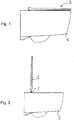
- a toilet in this case a simple toilet without shower function, with a ceramic toilet body 1 and mounted thereon and in its horizontal rotational position flat flat set 2.
- An axis of rotation of the rotational movement of the flat cover 2 is in their in Fig. 1 left end in the thickened area and thus at the wall end.
- the toilet body 1 is for mounting with his in Fig. 1 provided to the left-facing outer surface hanging on a bathroom wall.
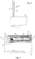
- Fig. 2 shows the toilet Fig. 1 , wherein the flat clothing is folded up as a whole, that is to say cover part 4 and seat part 5 (FIG. Fig. 3 ) in common, and from their attachment to two pairs provided (in Fig. 2 one behind the other) fasteners 3 has been deducted upwards.
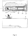
- Fig. 4 shows the thickened area (from Fig. 1 left) of the flat cover 2 in front view and cut on the toilet body 1; for clarity, the axis of rotation 6 is marked by dash-dotted lines.
- the flat cover 2 is placed on the two fasteners 3, of which Fig. 4 a cut shows.
- This fastener 3 is screwed in a manner not shown and known per se with a vertical threaded rod in a vertical hole of the ceramic toilet body 1.
- a bottom plate About a bottom plate, it has a pin, which has a in Fig. 5 better visible and pointing to the top right inclined surface 7 shows.
- the inclined surface 7 is at an angle of about 25 ° to the vertical and is flat apart from a rounding in the upper region of the pin.
- a magnet 8 is provided, which terminates flush with the inclined surface 7 and to which there is a counter magnet 9 in a further inclined surface 10 in a corresponding counterpart. This counterpart will be further described below.
- Fig. 4 shows the state in which the pin of the fastener 3 is received in a receptacle 11 in the seat part 5 and thereby fits precisely into the mentioned counterpart with the magnet 9 and held there by magnetic frictional engagement (in addition, a clamping or locking be given)
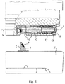
- Fig. 5 shows the disconnected state and corresponds with it Fig. 2 ,
- the 4 to 6 show in the seat part 5, a cylindrical chamber which communicates with the receptacle 11 and in which a cartridge-like locking element 12 is guided horizontally displaceable.
- the chamber and the locking element 12 are coaxial with the axis of rotation 6 and the locking element 12 is supported with a shoulder pointing to the right via a coil spring 13 on a screw-14, which closes the chamber to the right.
- the cover part 4 is arranged, with one of its rotatable support serving element, which is substantially a coaxial to the rotation axis 6, but not cylindrically symmetric pin receptacle 15.
- a corresponding pin 16 in the locking element 12 engages in Fig. 4 in this recording 15 and in the Fig. 5 and 6 Not. Accordingly, it consists in Fig. 4 a positive connection between the seat part 5 and cover part 4 and in the Fig. 5 and 6 Not. Therefore, the lid part 15 in Fig. 5 be taken away and missing in Fig. 6 ,
- the horizontal longitudinal displacement of the locking element 12 is the basis for this function and takes place in the interplay between the spring force of the compression-loaded coil spring 13 (which in Fig. 4 is more compressed than in Fig. 5 ) and a horizontal locking force, by the interaction between the two inclined surfaces 7 and 10 during insertion of the pin of the fastener 3 in the receptacle 11 (ie of the situation in Fig. 5 in the in Fig. 4 ) arises.
- the pin penetrates into a matching recess in the left area of the locking element 12 (as part of the receptacle 11), wherein the two inclined surfaces 7 and 10 interact with each other, and moves the locking element 12 upon pressing the flat set 2 on the toilet Body 1 horizontally, ie in the 4 to 6 to the right, until the pin the receptacle 11 according to Fig. 4 completely fills and the two magnets 8 and 9 are directly coupled together.
- the flat cover 2 is mounted on the toilet body 1 and cover part 4 and seat part 5 are pivotally connected to each other by engagement of the pin 16 in the receptacle 15 in the cover part 4th
- the locking element 12 is in two parts (different hatching), wherein a right in the figures right part with the pin 16 form fit with respect to torque transmission in the receptacle of the element 15 of the cover part 4 engage can and is thus coupled with respect to the rotational movement of it.
- Fig. 4 shows a recording of an upwardly projecting projection 18 of the right part of the locking element 12 in a corresponding longitudinal groove (in the axial direction) in the chamber of the seat part 5, wherein around the periphery of this chamber (with respect to the axis of rotation 6) around a plurality of such guides, such three, are given.
- a left part is rotatable relative to the right part and in turn positively coupled with respect to torque transmission with the seat part 5.
- the right part of the locking element 12 is positively coupled to the right part of the rotary damper 17 and the left part with its left part, so that the torque coupling ultimately causes a damping by the rotary damper 17 between the cover part 4 and seat part 5 during relative rotation therebetween.
Landscapes
- Health & Medical Sciences (AREA)
- Public Health (AREA)
- Toilet Supplies (AREA)
Priority Applications (1)
| Application Number | Priority Date | Filing Date | Title |
|---|---|---|---|
| EP18153802.6A EP3517009B1 (fr) | 2018-01-29 | 2018-01-29 | Ensemble formant abattant pour toilettes avec au moins un élément de fixation et toilettes dotées de dispositif de verrouillage |
Applications Claiming Priority (1)
| Application Number | Priority Date | Filing Date | Title |
|---|---|---|---|
| EP18153802.6A EP3517009B1 (fr) | 2018-01-29 | 2018-01-29 | Ensemble formant abattant pour toilettes avec au moins un élément de fixation et toilettes dotées de dispositif de verrouillage |
Publications (2)
| Publication Number | Publication Date |
|---|---|
| EP3517009A1 true EP3517009A1 (fr) | 2019-07-31 |
| EP3517009B1 EP3517009B1 (fr) | 2022-06-15 |
Family
ID=61187076
Family Applications (1)
| Application Number | Title | Priority Date | Filing Date |
|---|---|---|---|
| EP18153802.6A Active EP3517009B1 (fr) | 2018-01-29 | 2018-01-29 | Ensemble formant abattant pour toilettes avec au moins un élément de fixation et toilettes dotées de dispositif de verrouillage |
Country Status (1)
| Country | Link |
|---|---|
| EP (1) | EP3517009B1 (fr) |
Cited By (2)
| Publication number | Priority date | Publication date | Assignee | Title |
|---|---|---|---|---|
| AT17581U1 (de) * | 2020-01-23 | 2022-07-15 | 5Rk S R O | Scharnier für Toilettensitz |
| EP4316325A1 (fr) * | 2022-08-04 | 2024-02-07 | Roca Sanitario, S. A. | Siège de wc à fonctions bidet et wc à fonctions bidet comprenant ledit siège |
Citations (1)
| Publication number | Priority date | Publication date | Assignee | Title |
|---|---|---|---|---|
| CN205197892U (zh) * | 2015-11-09 | 2016-05-04 | 杨添丁 | 马桶盖板的一键式快速拆装机构 |
-
2018
- 2018-01-29 EP EP18153802.6A patent/EP3517009B1/fr active Active
Patent Citations (1)
| Publication number | Priority date | Publication date | Assignee | Title |
|---|---|---|---|---|
| CN205197892U (zh) * | 2015-11-09 | 2016-05-04 | 杨添丁 | 马桶盖板的一键式快速拆装机构 |
Cited By (2)
| Publication number | Priority date | Publication date | Assignee | Title |
|---|---|---|---|---|
| AT17581U1 (de) * | 2020-01-23 | 2022-07-15 | 5Rk S R O | Scharnier für Toilettensitz |
| EP4316325A1 (fr) * | 2022-08-04 | 2024-02-07 | Roca Sanitario, S. A. | Siège de wc à fonctions bidet et wc à fonctions bidet comprenant ledit siège |
Also Published As
| Publication number | Publication date |
|---|---|
| EP3517009B1 (fr) | 2022-06-15 |
Similar Documents
| Publication | Publication Date | Title |
|---|---|---|
| DE102006020205B4 (de) | Befestigung für einen WC-Sitz | |
| AT503418A4 (de) | Schublade mit wenigstens einer hölzernen schubladenseitenwand | |
| DE19633667A1 (de) | Schnappschloß | |
| DE202009009156U1 (de) | Toilettensitzscharnier mit sanfter Schließfunktion | |
| AT8214U1 (de) | Möbel | |
| WO2016142302A1 (fr) | Charnière et ensemble lunette-abattant pour siège de wc | |
| EP2371253A2 (fr) | Siège de toilettes | |
| EP3517009B1 (fr) | Ensemble formant abattant pour toilettes avec au moins un élément de fixation et toilettes dotées de dispositif de verrouillage | |
| EP2118414A1 (fr) | Armature de verrouillage et ensemble de pièces pour cette armature | |
| DE202012100472U1 (de) | Ein schnell demontierbares Scharnier eines WC-Sitzdeckels mit Absenkautomatik | |
| EP3277899A1 (fr) | Système de poignée de porte d'un véhicule automobile | |
| EP2949842A1 (fr) | Système de poignée de porte pour un véhicule | |
| DE60306221T2 (de) | Vorrichtung zum Öffnen und Schliessen eines Stöpsels einer Ablaufgarnitur | |
| DE102016125047A1 (de) | WC-Sitzgelenkanordnung | |
| DE3424305C2 (de) | Betätigungseinrichtung für einen Verschluß mit Schubfalle | |
| DE202018000445U1 (de) | WC-Deckelgarnitur und WC mit Verriegelungseinrichtung | |
| DE202011000675U1 (de) | Schrank, insbesondere Gasflaschenschrank | |
| EP3851004B1 (fr) | Dispositif de montage destiné au montage amovible d'une pièce de garniture sur un corps de wc | |
| EP1197621A1 (fr) | Dispositif de verrouillage pour coffre de rangement | |
| DE19938787A1 (de) | Reinigungseinrichtung, insbesondere zum Reinigen von Toiletten, Hohlkörpern o. dgl. | |
| EP0467122A1 (fr) | Douille pour broches de ferrures ou charnières | |
| EP3260609B1 (fr) | Dispositif d'actionnement pour un réservoir de chasse d'eau encastré | |
| DE202018002362U1 (de) | WC-Garnitur und WC mit Verriegelungseinrichtung | |
| DE102004001155B4 (de) | Uriniervorrichtung zur Anbringung an einer eine Toilettenbrille und/oder einen Toilettendeckel aufweisenden Toilettenschüssel | |
| WO2016071487A1 (fr) | Charnière et ensemble lunette-abattant pour siège de wc |
Legal Events
| Date | Code | Title | Description |
|---|---|---|---|
| PUAI | Public reference made under article 153(3) epc to a published international application that has entered the european phase |
Free format text: ORIGINAL CODE: 0009012 |
|
| STAA | Information on the status of an ep patent application or granted ep patent |
Free format text: STATUS: REQUEST FOR EXAMINATION WAS MADE |
|
| 17P | Request for examination filed |
Effective date: 20180816 |
|
| AK | Designated contracting states |
Kind code of ref document: A1 Designated state(s): AL AT BE BG CH CY CZ DE DK EE ES FI FR GB GR HR HU IE IS IT LI LT LU LV MC MK MT NL NO PL PT RO RS SE SI SK SM TR |
|
| AX | Request for extension of the european patent |
Extension state: BA ME |
|
| RBV | Designated contracting states (corrected) |
Designated state(s): AL AT BE BG CH CY CZ DE DK EE ES FI FR GB GR HR HU IE IS IT LI LT LU LV MC MK MT NL NO PL PT RO RS SE SI SK SM TR |
|
| GRAP | Despatch of communication of intention to grant a patent |
Free format text: ORIGINAL CODE: EPIDOSNIGR1 |
|
| STAA | Information on the status of an ep patent application or granted ep patent |
Free format text: STATUS: GRANT OF PATENT IS INTENDED |
|
| INTG | Intention to grant announced |
Effective date: 20210708 |
|
| GRAJ | Information related to disapproval of communication of intention to grant by the applicant or resumption of examination proceedings by the epo deleted |
Free format text: ORIGINAL CODE: EPIDOSDIGR1 |
|
| STAA | Information on the status of an ep patent application or granted ep patent |
Free format text: STATUS: REQUEST FOR EXAMINATION WAS MADE |
|
| INTC | Intention to grant announced (deleted) | ||
| GRAP | Despatch of communication of intention to grant a patent |
Free format text: ORIGINAL CODE: EPIDOSNIGR1 |
|
| STAA | Information on the status of an ep patent application or granted ep patent |
Free format text: STATUS: GRANT OF PATENT IS INTENDED |
|
| INTG | Intention to grant announced |
Effective date: 20220107 |
|
| GRAS | Grant fee paid |
Free format text: ORIGINAL CODE: EPIDOSNIGR3 |
|
| GRAA | (expected) grant |
Free format text: ORIGINAL CODE: 0009210 |
|
| STAA | Information on the status of an ep patent application or granted ep patent |
Free format text: STATUS: THE PATENT HAS BEEN GRANTED |
|
| AK | Designated contracting states |
Kind code of ref document: B1 Designated state(s): AL AT BE BG CH CY CZ DE DK EE ES FI FR GB GR HR HU IE IS IT LI LT LU LV MC MK MT NL NO PL PT RO RS SE SI SK SM TR |
|
| REG | Reference to a national code |
Ref country code: CH Ref legal event code: EP Ref country code: GB Ref legal event code: FG4D Free format text: NOT ENGLISH |
|
| REG | Reference to a national code |
Ref country code: IE Ref legal event code: FG4D Free format text: LANGUAGE OF EP DOCUMENT: GERMAN |
|
| REG | Reference to a national code |
Ref country code: DE Ref legal event code: R096 Ref document number: 502018009900 Country of ref document: DE |
|
| REG | Reference to a national code |
Ref country code: AT Ref legal event code: REF Ref document number: 1497866 Country of ref document: AT Kind code of ref document: T Effective date: 20220715 |
|
| REG | Reference to a national code |
Ref country code: LT Ref legal event code: MG9D |
|
| REG | Reference to a national code |
Ref country code: NL Ref legal event code: MP Effective date: 20220615 |
|
| PG25 | Lapsed in a contracting state [announced via postgrant information from national office to epo] |
Ref country code: SE Free format text: LAPSE BECAUSE OF FAILURE TO SUBMIT A TRANSLATION OF THE DESCRIPTION OR TO PAY THE FEE WITHIN THE PRESCRIBED TIME-LIMIT Effective date: 20220615 Ref country code: NO Free format text: LAPSE BECAUSE OF FAILURE TO SUBMIT A TRANSLATION OF THE DESCRIPTION OR TO PAY THE FEE WITHIN THE PRESCRIBED TIME-LIMIT Effective date: 20220915 Ref country code: LT Free format text: LAPSE BECAUSE OF FAILURE TO SUBMIT A TRANSLATION OF THE DESCRIPTION OR TO PAY THE FEE WITHIN THE PRESCRIBED TIME-LIMIT Effective date: 20220615 Ref country code: HR Free format text: LAPSE BECAUSE OF FAILURE TO SUBMIT A TRANSLATION OF THE DESCRIPTION OR TO PAY THE FEE WITHIN THE PRESCRIBED TIME-LIMIT Effective date: 20220615 Ref country code: GR Free format text: LAPSE BECAUSE OF FAILURE TO SUBMIT A TRANSLATION OF THE DESCRIPTION OR TO PAY THE FEE WITHIN THE PRESCRIBED TIME-LIMIT Effective date: 20220916 Ref country code: FI Free format text: LAPSE BECAUSE OF FAILURE TO SUBMIT A TRANSLATION OF THE DESCRIPTION OR TO PAY THE FEE WITHIN THE PRESCRIBED TIME-LIMIT Effective date: 20220615 Ref country code: BG Free format text: LAPSE BECAUSE OF FAILURE TO SUBMIT A TRANSLATION OF THE DESCRIPTION OR TO PAY THE FEE WITHIN THE PRESCRIBED TIME-LIMIT Effective date: 20220915 |
|
| PG25 | Lapsed in a contracting state [announced via postgrant information from national office to epo] |
Ref country code: RS Free format text: LAPSE BECAUSE OF FAILURE TO SUBMIT A TRANSLATION OF THE DESCRIPTION OR TO PAY THE FEE WITHIN THE PRESCRIBED TIME-LIMIT Effective date: 20220615 Ref country code: LV Free format text: LAPSE BECAUSE OF FAILURE TO SUBMIT A TRANSLATION OF THE DESCRIPTION OR TO PAY THE FEE WITHIN THE PRESCRIBED TIME-LIMIT Effective date: 20220615 |
|
| PG25 | Lapsed in a contracting state [announced via postgrant information from national office to epo] |
Ref country code: NL Free format text: LAPSE BECAUSE OF FAILURE TO SUBMIT A TRANSLATION OF THE DESCRIPTION OR TO PAY THE FEE WITHIN THE PRESCRIBED TIME-LIMIT Effective date: 20220615 |
|
| PG25 | Lapsed in a contracting state [announced via postgrant information from national office to epo] |
Ref country code: SM Free format text: LAPSE BECAUSE OF FAILURE TO SUBMIT A TRANSLATION OF THE DESCRIPTION OR TO PAY THE FEE WITHIN THE PRESCRIBED TIME-LIMIT Effective date: 20220615 Ref country code: SK Free format text: LAPSE BECAUSE OF FAILURE TO SUBMIT A TRANSLATION OF THE DESCRIPTION OR TO PAY THE FEE WITHIN THE PRESCRIBED TIME-LIMIT Effective date: 20220615 Ref country code: RO Free format text: LAPSE BECAUSE OF FAILURE TO SUBMIT A TRANSLATION OF THE DESCRIPTION OR TO PAY THE FEE WITHIN THE PRESCRIBED TIME-LIMIT Effective date: 20220615 Ref country code: PT Free format text: LAPSE BECAUSE OF FAILURE TO SUBMIT A TRANSLATION OF THE DESCRIPTION OR TO PAY THE FEE WITHIN THE PRESCRIBED TIME-LIMIT Effective date: 20221017 Ref country code: ES Free format text: LAPSE BECAUSE OF FAILURE TO SUBMIT A TRANSLATION OF THE DESCRIPTION OR TO PAY THE FEE WITHIN THE PRESCRIBED TIME-LIMIT Effective date: 20220615 Ref country code: EE Free format text: LAPSE BECAUSE OF FAILURE TO SUBMIT A TRANSLATION OF THE DESCRIPTION OR TO PAY THE FEE WITHIN THE PRESCRIBED TIME-LIMIT Effective date: 20220615 Ref country code: CZ Free format text: LAPSE BECAUSE OF FAILURE TO SUBMIT A TRANSLATION OF THE DESCRIPTION OR TO PAY THE FEE WITHIN THE PRESCRIBED TIME-LIMIT Effective date: 20220615 |
|
| PG25 | Lapsed in a contracting state [announced via postgrant information from national office to epo] |
Ref country code: PL Free format text: LAPSE BECAUSE OF FAILURE TO SUBMIT A TRANSLATION OF THE DESCRIPTION OR TO PAY THE FEE WITHIN THE PRESCRIBED TIME-LIMIT Effective date: 20220615 Ref country code: IS Free format text: LAPSE BECAUSE OF FAILURE TO SUBMIT A TRANSLATION OF THE DESCRIPTION OR TO PAY THE FEE WITHIN THE PRESCRIBED TIME-LIMIT Effective date: 20221015 |
|
| REG | Reference to a national code |
Ref country code: DE Ref legal event code: R097 Ref document number: 502018009900 Country of ref document: DE |
|
| PG25 | Lapsed in a contracting state [announced via postgrant information from national office to epo] |
Ref country code: AL Free format text: LAPSE BECAUSE OF FAILURE TO SUBMIT A TRANSLATION OF THE DESCRIPTION OR TO PAY THE FEE WITHIN THE PRESCRIBED TIME-LIMIT Effective date: 20220615 |
|
| PLBE | No opposition filed within time limit |
Free format text: ORIGINAL CODE: 0009261 |
|
| STAA | Information on the status of an ep patent application or granted ep patent |
Free format text: STATUS: NO OPPOSITION FILED WITHIN TIME LIMIT |
|
| PG25 | Lapsed in a contracting state [announced via postgrant information from national office to epo] |
Ref country code: DK Free format text: LAPSE BECAUSE OF FAILURE TO SUBMIT A TRANSLATION OF THE DESCRIPTION OR TO PAY THE FEE WITHIN THE PRESCRIBED TIME-LIMIT Effective date: 20220615 |
|
| 26N | No opposition filed |
Effective date: 20230316 |
|
| PG25 | Lapsed in a contracting state [announced via postgrant information from national office to epo] |
Ref country code: SI Free format text: LAPSE BECAUSE OF FAILURE TO SUBMIT A TRANSLATION OF THE DESCRIPTION OR TO PAY THE FEE WITHIN THE PRESCRIBED TIME-LIMIT Effective date: 20220615 |
|
| P01 | Opt-out of the competence of the unified patent court (upc) registered |
Effective date: 20230507 |
|
| GBPC | Gb: european patent ceased through non-payment of renewal fee |
Effective date: 20230129 |
|
| PG25 | Lapsed in a contracting state [announced via postgrant information from national office to epo] |
Ref country code: LU Free format text: LAPSE BECAUSE OF NON-PAYMENT OF DUE FEES Effective date: 20230129 |
|
| REG | Reference to a national code |
Ref country code: BE Ref legal event code: MM Effective date: 20230131 |
|
| PG25 | Lapsed in a contracting state [announced via postgrant information from national office to epo] |
Ref country code: GB Free format text: LAPSE BECAUSE OF NON-PAYMENT OF DUE FEES Effective date: 20230129 |
|
| PG25 | Lapsed in a contracting state [announced via postgrant information from national office to epo] |
Ref country code: FR Free format text: LAPSE BECAUSE OF NON-PAYMENT OF DUE FEES Effective date: 20230131 Ref country code: BE Free format text: LAPSE BECAUSE OF NON-PAYMENT OF DUE FEES Effective date: 20230131 |
|
| PG25 | Lapsed in a contracting state [announced via postgrant information from national office to epo] |
Ref country code: IT Free format text: LAPSE BECAUSE OF FAILURE TO SUBMIT A TRANSLATION OF THE DESCRIPTION OR TO PAY THE FEE WITHIN THE PRESCRIBED TIME-LIMIT Effective date: 20220615 Ref country code: IE Free format text: LAPSE BECAUSE OF NON-PAYMENT OF DUE FEES Effective date: 20230129 |
|
| PGFP | Annual fee paid to national office [announced via postgrant information from national office to epo] |
Ref country code: AT Payment date: 20240118 Year of fee payment: 7 |
|
| PGFP | Annual fee paid to national office [announced via postgrant information from national office to epo] |
Ref country code: DE Payment date: 20240119 Year of fee payment: 7 Ref country code: CH Payment date: 20240202 Year of fee payment: 7 |