EP3517009A1 - Toilet lid fitting and water closet with locking device - Google Patents
Toilet lid fitting and water closet with locking device Download PDFInfo
- Publication number
- EP3517009A1 EP3517009A1 EP18153802.6A EP18153802A EP3517009A1 EP 3517009 A1 EP3517009 A1 EP 3517009A1 EP 18153802 A EP18153802 A EP 18153802A EP 3517009 A1 EP3517009 A1 EP 3517009A1
- Authority
- EP
- European Patent Office
- Prior art keywords
- cover
- locking
- toilet
- seat
- seat part
- Prior art date
- Legal status (The legal status is an assumption and is not a legal conclusion. Google has not performed a legal analysis and makes no representation as to the accuracy of the status listed.)
- Granted
Links
- XLYOFNOQVPJJNP-UHFFFAOYSA-N water Substances O XLYOFNOQVPJJNP-UHFFFAOYSA-N 0.000 title description 2
- 230000005540 biological transmission Effects 0.000 claims description 5
- 238000013016 damping Methods 0.000 claims description 5
- 239000000919 ceramic Substances 0.000 description 5
- 238000004140 cleaning Methods 0.000 description 3
- 238000010276 construction Methods 0.000 description 2
- 230000008878 coupling Effects 0.000 description 2
- 238000010168 coupling process Methods 0.000 description 2
- 238000005859 coupling reaction Methods 0.000 description 2
- 230000003993 interaction Effects 0.000 description 2
- 230000006835 compression Effects 0.000 description 1
- 238000007906 compression Methods 0.000 description 1
- 238000006073 displacement reaction Methods 0.000 description 1
- 230000002349 favourable effect Effects 0.000 description 1
- 230000012447 hatching Effects 0.000 description 1
- 238000003780 insertion Methods 0.000 description 1
- 230000037431 insertion Effects 0.000 description 1
- 230000010354 integration Effects 0.000 description 1
- 230000013011 mating Effects 0.000 description 1
- 239000000725 suspension Substances 0.000 description 1
Images
Classifications
-
- A—HUMAN NECESSITIES
- A47—FURNITURE; DOMESTIC ARTICLES OR APPLIANCES; COFFEE MILLS; SPICE MILLS; SUCTION CLEANERS IN GENERAL
- A47K—SANITARY EQUIPMENT NOT OTHERWISE PROVIDED FOR; TOILET ACCESSORIES
- A47K13/00—Seats or covers for all kinds of closets
- A47K13/24—Parts or details not covered in, or of interest apart from, groups A47K13/02 - A47K13/22, e.g. devices imparting a swinging or vibrating motion to the seats
- A47K13/26—Mounting devices for seats or covers
-
- A—HUMAN NECESSITIES
- A47—FURNITURE; DOMESTIC ARTICLES OR APPLIANCES; COFFEE MILLS; SPICE MILLS; SUCTION CLEANERS IN GENERAL
- A47K—SANITARY EQUIPMENT NOT OTHERWISE PROVIDED FOR; TOILET ACCESSORIES
- A47K13/00—Seats or covers for all kinds of closets
- A47K13/12—Hinges
Definitions
- the present invention relates to a toilet set for a toilet.
- Toilets water closets
- a toilet body often made of ceramic
- a toilet seat and a lid are provided.
- the toilet seat allows the user to sit on it and can be folded up regularly around an axis transverse to the rear of the toilet.
- a likewise usually provided toilet lid for closing the toilet bowl which usually also covers the seat with.
- WCs have to be cleaned very frequently and thoroughly, and cleaning with regard to their functional properties is an essential aspect. This also affects the toilet seat and the toilet lid. Accordingly, it is generally known to provide fastening devices with which these parts can be reduced in a simplified manner from the toilet body. "Simplified” means that, for example, the loosening of screw connections, with which hinge parts are mounted through vertical holes in the toilet body, is too cumbersome for regular cleaning and cleaning personnel and consequently no dismantling is required.
- Analog shows the DE 10 2006 020 205 A1 as much younger document a variant with matching axis of rotation of the lid and seat and an operating option behind and outside the lid on both sides.
- the cover with the seat can also be removed there.
- a sleeve with a helical ramp provided therein is responsible for releasing the lid and seat from the toilet body as a result of being flipped up.
- the ramp moves a spring, which releases a locking engagement with a fixing pin on the toilet body.
- the EP 2 679 127 A1 shows a solution in which the folding also opens a positive connection and thus cover and seat can be removed.
- the invention has for its object to provide a toilet cover set and a toilet with further improved performance characteristics.
- a toilet cover set for mounting on a toilet body with a toilet bowl, which has flat cover: a cover part for covering the toilet bowl, a seat part as a seat for a user and a locking device for locking the seat part or the cover part with a further part of the flat clothing, at least one fastening element for fixing the flat clothing on the WC body, which is designed to be fastened on the WC body and then allow the flat clothing to be fastened to the at least one fastening element, wherein the flat set is adapted to automatically actuate the locking means by attaching the flat garniture to the fastener and releasing it, and by an appropriately equipped WC.
- a basic idea of the invention is to use the attachment of an existing at least from the lid part and the seat part cover set on the toilet body in addition to the automatic actuation of the locking device. In other words, by removing the cover assembly from the toilet body unlocking and locking by a fixture instead.
- the flat cover consists of the cover part and the seat part and has no further mounting part for mounting on the fastening element
- the locking part relates to the seat part and cover part. Consequently, these two parts are also detachable from each other after assembly of the fastener, while they are locked together in the mounted state on the fastener.
- this flat fitting may also have a mounting part, wherein the locking by the locking device then may also affect the relationship between this mounting part and the seat part or the cover part (or between all three parts).
- the invention requires no further actuators to operate the locking device and no additional handles.
- the removal (and the necessary actions) will do the unlocking at the same time.
- the invention thus offers a particularly simple operation and with regard to the exterior design of the parts involved also the possibility of a particularly simple design.
- the mentioned fastener is usually provided at least twice, because typically two attachment points are present on a toilet body, for example.
- Vertical openings through a toilet ceramic through, in each case a fastener, the opening can be screwed enforcing.
- the fastener can then each z. B. have a pin for placing the flat sheet set thereon.
- a possible and favorable embodiment provides the part of the cover set a receptacle for the (at least one) fastener before, in many practical cases, two receptacles for each one fastener.
- the flat fitting is made by placing and thereby inserting the (respective) fastener secured in the receptacle and removed by a reverse movement.
- the holder in the attached state can be done in different ways, such as a snap mechanism, a magnetic force, etc.
- the fastening of the flat clothing is usually associated with a vertical movement, which can be used according to the invention.
- a device for translating this vertical movement may be provided in an angled locking movement, wherein the locking movement is preferably horizontal (as all directional information relative to a mounted state of the flat set on a toilet).
- At least one inclined surface which may be provided on the fastening element and / or in the receptacle, in order to convert the vertical into the angled movement.
- this is preferably true for the addressed possible plurality of fasteners and receptacles and of course also inclined surfaces may be provided on the fastener and the associated receptacle to interact with each other.
- “oblique” means a suitable angle with respect to the vertical direction of movement, that is to say preferably an angle of at least 10 ° and at most 60 ° and more preferably at least 15 ° and at most 50 ° or at least 20 ° and at most 40 °.
- the angle refers to those surface parts that are really essential for the implementation of the movement, that is, for example, come into contact with a mating surface.
- the inclined surface (s) need not be flat, but may also be somewhat convex or concave or otherwise domed.
- the angled and preferably horizontal direction of the locking movement may be embodied by the movement of a locking element which is provided in the cover part or in the seat part (or possibly also in the mounting part) and the lock by establishing and releasing a positive connection with a others of the parts mentioned causes or repeals.
- the said inclined surface or one of these inclined surfaces may be provided on or in such a locking element, which can move in a receptacle of the corresponding lid, seat or mounting member, preferably a cylindrical receptacle, which in turn preferably coaxially to the axis of rotation of a rotational mobility the lid part and / or seat part is.
- the locking element can cause a positive connection by locking, which also generates a torque transmission for the rotary damper, ie z. B. not only locked the lid part relative to the seat part with respect to the assembly, but also with regard to the transmission of a relative rotation between these two parts on the rotary damper.
- the rotary damper can then be held in a form-fitting manner, for example, in the locking element, with which it is moved and which in turn is positively guided.
- At least one rotary damper known per se can be provided for damping at least one rotational mobility, for example for the cover part, wherein the rotary damper is preferably integrated in the described locking element and moved during the locking movement.
- the integration of the rotary damper in the locking element and the Mitieri allow particularly compact and simple constructions.
- the locking element could be functional part of one of the rotary bearings for the described rotational movements, in particular a bearing journal or a receptacle for such a journal.
- the locking element may be resiliently mounted, for example, be supported by a coil spring on an abutment or be attached to a bearing via such a coil spring which is loaded on train.
- a coil spring on an abutment
- a bearing via such a coil spring which is loaded on train.
- the receptacle for the fastening element (or the receptacles for the fastening elements) is preferably provided in the cover part or seat part and not in a separate mounting part, because preferably the flat cover consists only of the cover part and seat part.
- the seat part which also contains the locking device with the locking element and a rotary damper, in pairs and in each case in the outer region of a part surrounding the axis of rotation of the seat part and with a largely cylindrically symmetrical apart from the inclined surface to this axis of rotation construction.
- the invention also relates to a complete toilet with a corresponding flat fitting, wherein the fastener in the toilet can also be integrated, so in turn not necessarily of the toilet body must be solvable (as is usually the case with classic ceramic toilet bodies and the already mentioned vertical holes therein).
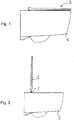
- a toilet in this case a simple toilet without shower function, with a ceramic toilet body 1 and mounted thereon and in its horizontal rotational position flat flat set 2.
- An axis of rotation of the rotational movement of the flat cover 2 is in their in Fig. 1 left end in the thickened area and thus at the wall end.
- the toilet body 1 is for mounting with his in Fig. 1 provided to the left-facing outer surface hanging on a bathroom wall.
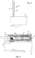
- Fig. 2 shows the toilet Fig. 1 , wherein the flat clothing is folded up as a whole, that is to say cover part 4 and seat part 5 (FIG. Fig. 3 ) in common, and from their attachment to two pairs provided (in Fig. 2 one behind the other) fasteners 3 has been deducted upwards.
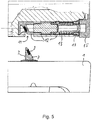
- Fig. 4 shows the thickened area (from Fig. 1 left) of the flat cover 2 in front view and cut on the toilet body 1; for clarity, the axis of rotation 6 is marked by dash-dotted lines.
- the flat cover 2 is placed on the two fasteners 3, of which Fig. 4 a cut shows.
- This fastener 3 is screwed in a manner not shown and known per se with a vertical threaded rod in a vertical hole of the ceramic toilet body 1.
- a bottom plate About a bottom plate, it has a pin, which has a in Fig. 5 better visible and pointing to the top right inclined surface 7 shows.
- the inclined surface 7 is at an angle of about 25 ° to the vertical and is flat apart from a rounding in the upper region of the pin.
- a magnet 8 is provided, which terminates flush with the inclined surface 7 and to which there is a counter magnet 9 in a further inclined surface 10 in a corresponding counterpart. This counterpart will be further described below.
- Fig. 4 shows the state in which the pin of the fastener 3 is received in a receptacle 11 in the seat part 5 and thereby fits precisely into the mentioned counterpart with the magnet 9 and held there by magnetic frictional engagement (in addition, a clamping or locking be given)
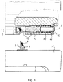
- Fig. 5 shows the disconnected state and corresponds with it Fig. 2 ,
- the 4 to 6 show in the seat part 5, a cylindrical chamber which communicates with the receptacle 11 and in which a cartridge-like locking element 12 is guided horizontally displaceable.
- the chamber and the locking element 12 are coaxial with the axis of rotation 6 and the locking element 12 is supported with a shoulder pointing to the right via a coil spring 13 on a screw-14, which closes the chamber to the right.
- the cover part 4 is arranged, with one of its rotatable support serving element, which is substantially a coaxial to the rotation axis 6, but not cylindrically symmetric pin receptacle 15.
- a corresponding pin 16 in the locking element 12 engages in Fig. 4 in this recording 15 and in the Fig. 5 and 6 Not. Accordingly, it consists in Fig. 4 a positive connection between the seat part 5 and cover part 4 and in the Fig. 5 and 6 Not. Therefore, the lid part 15 in Fig. 5 be taken away and missing in Fig. 6 ,
- the horizontal longitudinal displacement of the locking element 12 is the basis for this function and takes place in the interplay between the spring force of the compression-loaded coil spring 13 (which in Fig. 4 is more compressed than in Fig. 5 ) and a horizontal locking force, by the interaction between the two inclined surfaces 7 and 10 during insertion of the pin of the fastener 3 in the receptacle 11 (ie of the situation in Fig. 5 in the in Fig. 4 ) arises.
- the pin penetrates into a matching recess in the left area of the locking element 12 (as part of the receptacle 11), wherein the two inclined surfaces 7 and 10 interact with each other, and moves the locking element 12 upon pressing the flat set 2 on the toilet Body 1 horizontally, ie in the 4 to 6 to the right, until the pin the receptacle 11 according to Fig. 4 completely fills and the two magnets 8 and 9 are directly coupled together.
- the flat cover 2 is mounted on the toilet body 1 and cover part 4 and seat part 5 are pivotally connected to each other by engagement of the pin 16 in the receptacle 15 in the cover part 4th
- the locking element 12 is in two parts (different hatching), wherein a right in the figures right part with the pin 16 form fit with respect to torque transmission in the receptacle of the element 15 of the cover part 4 engage can and is thus coupled with respect to the rotational movement of it.
- Fig. 4 shows a recording of an upwardly projecting projection 18 of the right part of the locking element 12 in a corresponding longitudinal groove (in the axial direction) in the chamber of the seat part 5, wherein around the periphery of this chamber (with respect to the axis of rotation 6) around a plurality of such guides, such three, are given.
- a left part is rotatable relative to the right part and in turn positively coupled with respect to torque transmission with the seat part 5.
- the right part of the locking element 12 is positively coupled to the right part of the rotary damper 17 and the left part with its left part, so that the torque coupling ultimately causes a damping by the rotary damper 17 between the cover part 4 and seat part 5 during relative rotation therebetween.
Abstract
Die Erfindung betrifft ein WC und eine Deckelgarnitur (2) für ein WC mit einem Sitzteil (5) und einem Deckelteil (4), die bei Abnahme der Deckelgarnitur (2) von dem WC (1) automatisch voneinander entkoppelt und beim Wiederaufsetzen automatisch miteinander gekoppelt werden.The invention relates to a toilet and a cover set (2) for a toilet with a seat part (5) and a cover part (4) which, when the cover set (2) is removed from the toilet (1), is automatically decoupled from one another and is automatically coupled to one another when replaced become.
Description
Die vorliegende Erfindung bezieht sich auf eine WC-Deckelgarnitur für ein WC.The present invention relates to a toilet set for a toilet.
WCs (Wasserklosetts) weisen einen WC-Körper, oft aus Keramik, mit einer WC-Schüssel auf. Ferner sind meistens ein WC-Sitz und ein Deckel vorgesehen. Der WC-Sitz dient dem Benutzer zum Sitzen darauf und kann regelmäßig um eine im hinteren Bereich des WCs quer liegende Achse hochgeklappt werden. Gleiches gilt für einen ebenfalls meistens vorgesehenen WC-Deckel zum Verschließen der WC-Schüssel, der dabei in der Regel auch den Sitz mit abdeckt.Toilets (water closets) have a toilet body, often made of ceramic, with a toilet bowl. Furthermore, usually a toilet seat and a lid are provided. The toilet seat allows the user to sit on it and can be folded up regularly around an axis transverse to the rear of the toilet. The same applies to a likewise usually provided toilet lid for closing the toilet bowl, which usually also covers the seat with.
Es versteht sich von selbst, dass WCs besonders häufig und gründlich gereinigt werden müssen und die Reinigung hinsichtlich der Gebrauchseigenschaften einen wesentlichen Aspekt darstellt. Das betrifft auch den WC-Sitz und den WC-Deckel. Dementsprechend ist es grundsätzlich bekannt, Befestigungseinrichtungen vorzusehen, mit denen diese Teile vereinfacht von dem WC-Körper abgebaut werden können. "Vereinfacht" bedeutet, dass zum Beispiel das Lösen von Schraubverbindungen, mit denen Scharnierteile durch vertikale Löcher im WC-Körper hindurchgreifend montiert sind, für die regelmäßige Reinigung und Reinigungspersonal zu umständlich ist und demzufolge auf ein Abbauen verzichtet wird.It goes without saying that WCs have to be cleaned very frequently and thoroughly, and cleaning with regard to their functional properties is an essential aspect. This also affects the toilet seat and the toilet lid. Accordingly, it is generally known to provide fastening devices with which these parts can be reduced in a simplified manner from the toilet body. "Simplified" means that, for example, the loosening of screw connections, with which hinge parts are mounted through vertical holes in the toilet body, is too cumbersome for regular cleaning and cleaning personnel and consequently no dismantling is required.
Im Unterschied dazu zeigt z. B. die
Analog zeigt die
Bei der
Die
Der Erfindung liegt die Aufgabe zugrunde, eine WC-Deckelgarnitur und ein WC mit weiter verbesserten Gebrauchseigenschaften anzugeben.The invention has for its object to provide a toilet cover set and a toilet with further improved performance characteristics.
Diese Aufgabe wird gelöst durch eine WC-Deckelgarnitur zur Montage auf einem WC-Körper mit einer WC-Schüssel, welche Deckelgarnitur aufweist: einen Deckelteil zum Abdecken der WC-Schüssel, einen Sitzteil als Sitz für einen Benutzer und eine Verriegelungseinrichtung zum Verriegeln des Sitzteils oder des Deckelteils mit einem weiteren Teil der Deckelgarnitur, mindestens ein Befestigungselement zum Befestigen der Deckelgarnitur auf dem WC-Körper, welches dazu ausgelegt ist, seinerseits auf dem WC-Körper befestigt zu werden und danach eine Befestigung der Deckelgarnitur an dem zumindest einen Befestigungselement zu erlauben, wobei die Deckelgarnitur dazu ausgelegt ist, dass die Verriegelungseinrichtung durch das Befestigen der Deckelgarnitur an dem Befestigungselement und durch das davon Lösen selbsttätig betätigt wird, sowie durch ein entsprechend ausgestattetes WC.This object is achieved by a toilet cover set for mounting on a toilet body with a toilet bowl, which has flat cover: a cover part for covering the toilet bowl, a seat part as a seat for a user and a locking device for locking the seat part or the cover part with a further part of the flat clothing, at least one fastening element for fixing the flat clothing on the WC body, which is designed to be fastened on the WC body and then allow the flat clothing to be fastened to the at least one fastening element, wherein the flat set is adapted to automatically actuate the locking means by attaching the flat garniture to the fastener and releasing it, and by an appropriately equipped WC.
Eine Grundidee der Erfindung besteht darin, die Befestigung einer mindestens aus dem Deckelteil und dem Sitzteil bestehenden Deckelgarnitur auf dem WC-Körper zusätzlich zur selbsttätigen Betätigung der Verriegelungseinrichtung zu verwenden. In anderen Worten findet durch Abnahme der Deckelgarnitur von dem WC-Körper eine Entriegelung und durch eine Befestigung eine Verriegelung statt.A basic idea of the invention is to use the attachment of an existing at least from the lid part and the seat part cover set on the toilet body in addition to the automatic actuation of the locking device. In other words, by removing the cover assembly from the toilet body unlocking and locking by a fixture instead.
Wenn, was bevorzugt ist, die Deckelgarnitur aus dem Deckelteil und dem Sitzteil besteht und kein weiteres Montageteil zur Montage an dem Befestigungselement aufweist, dann betrifft die Verriegelung Sitzteil und Deckelteil. Folglich sind diese beiden Teile nach der Montage von dem Befestigungselement auch voneinander lösbar, während sie im an dem Befestigungselement montierten Zustand miteinander verriegelt sind.If, which is preferred, the flat cover consists of the cover part and the seat part and has no further mounting part for mounting on the fastening element, then the locking part relates to the seat part and cover part. Consequently, these two parts are also detachable from each other after assembly of the fastener, while they are locked together in the mounted state on the fastener.
Diese Deckelgarnitur kann allerdings auch ein Montageteil aufweisen, wobei die Verriegelung durch die Verriegelungseinrichtung dann auch das Verhältnis zwischen diesem Montageteil und dem Sitzteil oder dem Deckelteil (oder zwischen allen drei Teilen) betreffen kann.However, this flat fitting may also have a mounting part, wherein the locking by the locking device then may also affect the relationship between this mounting part and the seat part or the cover part (or between all three parts).
Erfindungsgemäß benötigt man keine weiteren Betätigungselemente zur Bedienung der Verriegelungseinrichtung und auch keine zusätzlichen Handgriffe. Das Abnehmen (und die dafür nötigen Handlungen) erledigt die Entriegelung gleichzeitig. Die Erfindung bietet damit eine besonders einfache Bedienung und hinsichtlich der Außengestaltung der beteiligten Teile auch die Möglichkeit eines besonders einfachen Designs.According to the invention requires no further actuators to operate the locking device and no additional handles. The removal (and the necessary actions) will do the unlocking at the same time. The invention thus offers a particularly simple operation and with regard to the exterior design of the parts involved also the possibility of a particularly simple design.
Das erwähnte Befestigungselement ist im Regelfall mindestens doppelt vorgesehen, weil typischerweise an einem WC-Körper zwei Befestigungspunkte vorliegen, bspw. vertikale Öffnungen durch eine WC-Keramik hindurch, an denen jeweils ein Befestigungselement die Öffnung durchsetzend festgeschraubt werden kann. Das Befestigungselement kann dann jeweils z. B. einen Zapfen zum Aufsetzen der Deckelgarnitur darauf aufweisen. Wenn hier von einem Befestigungselement im Singular geschrieben wird, sind solche doppelten Ausführungen inbegriffen und als Einheit gemeint.The mentioned fastener is usually provided at least twice, because typically two attachment points are present on a toilet body, for example. Vertical openings through a toilet ceramic through, in each case a fastener, the opening can be screwed enforcing. The fastener can then each z. B. have a pin for placing the flat sheet set thereon. When here is written by a fastener in the singular, such duplicate versions are included and meant as a unit.
Eine mögliche und günstige Ausgestaltung sieht seitens der Deckelgarnitur eine Aufnahme für das (zumindest eine) Befestigungselement vor, in vielen praktischen Fällen auch zwei Aufnahmen für je ein Befestigungselement. Die Deckelgarnitur wird durch Aufsetzen und dabei Einführen des (jeweiligen) Befestigungselements in die Aufnahme befestigt und durch eine umgekehrte Bewegung abgenommen. Die Halterung im aufgesetzten Zustand kann dabei in unterschiedlicher Form geschehen, etwa durch einen Schnappmechanismus, einen Magnetkraftschluss etc.A possible and favorable embodiment provides the part of the cover set a receptacle for the (at least one) fastener before, in many practical cases, two receptacles for each one fastener. The flat fitting is made by placing and thereby inserting the (respective) fastener secured in the receptacle and removed by a reverse movement. The holder in the attached state can be done in different ways, such as a snap mechanism, a magnetic force, etc.
Die Befestigung der Deckelgarnitur ist im Regelfall mit einer Vertikalbewegung verbunden, die erfindungsgemäß genutzt werden kann. Insbesondere kann eine Einrichtung zum Übersetzen dieser Vertikalbewegung in eine dazu gewinkelte Verriegelungsbewegung vorgesehen sein, wobei die Verriegelungsbewegung vorzugsweise horizontal ist (wie alle Richtungsangaben bezogen auf einen montierten Zustand der Deckelgarnitur auf einem WC).The fastening of the flat clothing is usually associated with a vertical movement, which can be used according to the invention. In particular, a device for translating this vertical movement may be provided in an angled locking movement, wherein the locking movement is preferably horizontal (as all directional information relative to a mounted state of the flat set on a toilet).
Eine Möglichkeit dazu sieht zumindest eine schräge Fläche vor, die an dem Befestigungselement und/oder in der Aufnahme vorgesehen sein kann, um die vertikale in die gewinkelte Bewegung zu überführen. Natürlich gilt das vorzugsweise für die angesprochene mögliche Mehrzahl von Befestigungselementen und Aufnahmen und natürlich können auch schräge Flächen am Befestigungselement und der zugeordneten Aufnahme vorgesehen sein, um in Wechselwirkung miteinander zu treten.One possibility for this is to provide at least one inclined surface, which may be provided on the fastening element and / or in the receptacle, in order to convert the vertical into the angled movement. Of course, this is preferably true for the addressed possible plurality of fasteners and receptacles and of course also inclined surfaces may be provided on the fastener and the associated receptacle to interact with each other.
"Schräg" bedeutet dabei einen geeigneten Winkel gegenüber der vertikalen Bewegungsrichtung, also vorzugsweise einen Winkel von mindestens 10° und höchstens 60° und weiter bevorzugterweise mindestens 15° und höchstens 50° oder mindestens 20° und höchstens 40°. Der Winkel bezieht sich dabei auf diejenigen Flächenteile, die für die Umsetzung der Bewegung wirklich wesentlich sind, also bspw. mit einer Gegenfläche in Kontakt kommen. Die schräge(n) Fläche(n) müssen insbesondere nicht eben sein, sondern können auch etwas konvex oder konkav oder anderweitig gewölbt sein.In this case, "oblique" means a suitable angle with respect to the vertical direction of movement, that is to say preferably an angle of at least 10 ° and at most 60 ° and more preferably at least 15 ° and at most 50 ° or at least 20 ° and at most 40 °. The angle refers to those surface parts that are really essential for the implementation of the movement, that is, for example, come into contact with a mating surface. In particular, the inclined surface (s) need not be flat, but may also be somewhat convex or concave or otherwise domed.
Die gewinkelte und vorzugsweise horizontale Richtung der Verriegelungsbewegung kann durch die Bewegung eines Riegelelements verkörpert sein, das im Deckelteil oder im Sitzteil (oder gegebenenfalls auch im Montageteil) vorgesehen ist und die Verriegelung durch Herstellen und Lösen eines Formschlusses mit einem anderen der genannten Teile bewirkt bzw. aufhebt. Insbesondere kann die erwähnte schräge Fläche oder eine dieser schrägen Flächen an oder in einem solchen Riegelelement vorgesehen sein, das sich in einer Aufnahme des entsprechenden Deckel-, Sitz- oder Montageteils bewegen kann, vorzugsweise einer zylindrischen Aufnahme, die wiederum vorzugsweise koaxial zur Drehachse einer Drehbeweglichkeit des Deckelteils und/oder Sitzteils ist.The angled and preferably horizontal direction of the locking movement may be embodied by the movement of a locking element which is provided in the cover part or in the seat part (or possibly also in the mounting part) and the lock by establishing and releasing a positive connection with a others of the parts mentioned causes or repeals. In particular, the said inclined surface or one of these inclined surfaces may be provided on or in such a locking element, which can move in a receptacle of the corresponding lid, seat or mounting member, preferably a cylindrical receptacle, which in turn preferably coaxially to the axis of rotation of a rotational mobility the lid part and / or seat part is.
Das Riegelelement kann durch die Verriegelung einen Formschluss bewirken, der auch eine Drehmomentübertragung für den Drehdämpfer erzeugt, also z. B. nicht nur den Deckelteil gegenüber dem Sitzteil hinsichtlich der Montage verriegelt, sondern auch hinsichtlich der Übertragung einer Relativdrehung zwischen diesen beiden Teilen auf den Drehdämpfer. Der Drehdämpfer kann dann dementsprechend selbst formschlüssig gehalten sein, bspw. im Riegelelement, mit dem er mitbewegt wird und das seinerseits formschlüssig geführt ist.The locking element can cause a positive connection by locking, which also generates a torque transmission for the rotary damper, ie z. B. not only locked the lid part relative to the seat part with respect to the assembly, but also with regard to the transmission of a relative rotation between these two parts on the rotary damper. The rotary damper can then be held in a form-fitting manner, for example, in the locking element, with which it is moved and which in turn is positively guided.
Bei einer weiteren Ausgestaltung kann zumindest ein an sich bekannter Drehdämpfer zum Dämpfen zumindest einer Drehbeweglichkeit vorgesehen sein, etwa für den Deckelteil, wobei der Drehdämpfer vorzugsweise in dem beschriebenen Riegelelement integriert und bei der Verriegelungsbewegung mit bewegt wird. Die Integration des Drehdämpfers in dem Riegelelement und die Mitbewegung ermöglichen besonders kompakte und einfache Konstruktionen.In a further embodiment, at least one rotary damper known per se can be provided for damping at least one rotational mobility, for example for the cover part, wherein the rotary damper is preferably integrated in the described locking element and moved during the locking movement. The integration of the rotary damper in the locking element and the Mitbewegung allow particularly compact and simple constructions.
Insbesondere kann es zwei Riegelelemente geben und jeweils einen Drehdämpfer, wobei einer davon zum Dämpfen der Drehbeweglichkeit des Sitzteils und der andere zum Dämpfen der Drehbeweglichkeit des Deckelteils eingesetzt wird. Durch formschlüssige oder drehbare Verbindungen zwischen den entsprechenden Teilen lässt sich das erreichen.In particular, there may be two locking elements and in each case one rotary damper, one of which is used for damping the rotational mobility of the seat part and the other for damping the rotational mobility of the cover part. By positive or rotatable connections between the corresponding parts can achieve this.
Weiterhin könnte das Riegelelement Funktionsteil eines der Drehlager für die beschriebenen Drehbeweglichkeiten sein, insbesondere ein Lagerzapfen oder eine Aufnahme für einen solchen Lagerzapfen.Furthermore, the locking element could be functional part of one of the rotary bearings for the described rotational movements, in particular a bearing journal or a receptacle for such a journal.
Das Riegelelement kann federnd gelagert sein, sich bspw. über eine Schraubenfeder an einem Gegenlager abstützen oder über eine solche Schraubenfeder, die auf Zug belastet wird, an einem Lager angehängt sein. Durch die Federkraft wird der Verriegelungskraft entgegengewirkt, die infolge des Montierens des Deckelteils auf dem WC-Körper entsteht und z. B. in ihrer Richtung umgesetzt wird von vertikal nach horizontal. Durch die Federung kann man besonders einfach dafür sorgen, dass bei der Entriegelung die entriegelte Position auch zuverlässig erreicht wird.The locking element may be resiliently mounted, for example, be supported by a coil spring on an abutment or be attached to a bearing via such a coil spring which is loaded on train. By the spring force of the locking force is counteracted, which arises as a result of mounting the cover part on the toilet body and z. B. is converted in their direction from vertical to horizontal. Due to the suspension, it is particularly easy to ensure that the unlocked position is reliably reached when unlocking.
Ferner ist die Aufnahme für das Befestigungselement (oder sind die Aufnahmen für die Befestigungselemente) vorzugsweise in dem Deckelteil oder Sitzteil und nicht in einem eigenen Montageteil vorgesehen, denn vorzugsweise besteht die Deckelgarnitur nur aus Deckelteil und Sitzteil. Beim Ausführungsbeispiel gilt dies für das Sitzteil, das außerdem die Verriegelungseinrichtung mit dem Riegelelement und einem Drehdämpfer enthält, und zwar paarweise und jeweils im äußeren Bereich eines die Drehachse umgebenden Teils des Sitzteils und mit einem abgesehen von der schrägen Fläche zu dieser Drehachse weitgehend zylindersymmetrischen Aufbau.Furthermore, the receptacle for the fastening element (or the receptacles for the fastening elements) is preferably provided in the cover part or seat part and not in a separate mounting part, because preferably the flat cover consists only of the cover part and seat part. In the embodiment, this applies to the seat part, which also contains the locking device with the locking element and a rotary damper, in pairs and in each case in the outer region of a part surrounding the axis of rotation of the seat part and with a largely cylindrically symmetrical apart from the inclined surface to this axis of rotation construction.
Schließlich betrifft die Erfindung auch ein komplettes WC mit einer entsprechenden Deckelgarnitur, wobei das Befestigungselement in dem WC auch integriert sein kann, also seinerseits nicht zwingend von dem WC-Körper lösbar sein muss (wie dies üblicherweise bei klassischen Keramik-WC-Körpern und den bereits erwähnten vertikalen Löchern darin der Fall ist).Finally, the invention also relates to a complete toilet with a corresponding flat fitting, wherein the fastener in the toilet can also be integrated, so in turn not necessarily of the toilet body must be solvable (as is usually the case with classic ceramic toilet bodies and the already mentioned vertical holes therein).
Im Folgenden wird die Erfindung anhand eines Ausführungsbeispiels näher erläutert. Dabei zeigen:
- Figur 1
- eine Seitenansicht eines erfindungsgemäßen WCs mit einem WC-Körper 1 und einer darauf
aufgesetzten Deckelgarnitur 2; Figur 2- eine analoge Seitenansicht, bei der die Deckelgarnitur hochgeklappt und aus einer Befestigung auf
Befestigungselementen 3 gelöst und nach oben gezogen worden ist; Figur 3- erneut eine analoge Seitenansicht, wobei ein
Deckelteil 4 und ein Sitzteil 5 derDeckelgarnitur 2 voneinander getrennt sind; Figur 4- in einer geschnittenen Detaildarstellung und Ansicht von vorne, also gegenüber den
Fig. 1 um 90° gedreht, einen rechten äußeren Bereich der Deckelgarnitur 2 auf dem WC-Körper 1 in dem zusammengesetzten Zustand ausbis 3Fig. 1 ; - Figur 5
- in analoger Ansicht zu
Fig. 4 die Situation ausFig. 2 , nämlich mit nach oben abgehobener, aber noch zusammenhängender Deckelgarnitur 2; und Figur 6- in einer weiteren zu den
Fig. 4 und5 analogen Ansicht die Situation ausFig. 3 , wobei der vom Sitzteil 5getrennte Deckelteil 4 nicht mehr mit dargestellt ist.
- FIG. 1
- a side view of a toilet according to the invention with a toilet body 1 and a lid set 2 placed thereon;
- FIG. 2
- an analogous side view, in which the flat cover has been folded up and released from an attachment to
fasteners 3 and pulled upwards; - FIG. 3
- again a similar side view, wherein a
cover part 4 and a seat part 5 of theflat cover 2 are separated from each other; - FIG. 4
- in a detailed sectional view and view from the front, ie opposite the
Fig. 1 to 3 rotated by 90 °, a right outer portion of theflat clothing 2 on the toilet body 1 in the assembled stateFig. 1 ; - FIG. 5
- in analogue view too
Fig. 4 the situationFig. 2 , namely with upwardly lifted, but still contiguous cover set 2; and - FIG. 6
- in another to the
Fig. 4 and5 analog view the situationFig. 3 , wherein theseparate cover part 4 from the seat part 5 is no longer shown.
In
Diese Demontage von den Befestigungselementen 3 entkoppelt Deckelteil 4 und Sitzteil 5 voneinander, sodass diese gemäß
Über einer Bodenplatte weist es einen Zapfen auf, der eine in
Zunächst ist festzuhalten, dass
Die
Axial weiter rechts und außerhalb des Einschraubdeckels 14 ist in den
Die horizontale Längsverschiebbarkeit des Riegelelements 12 ist Grundlage für diese Funktion und erfolgt im Wechselspiel zwischen der Federkraft der auf Kompression belasteten Schraubenfeder 13 (die in
Dabei dringt der Zapfen in eine dazu passende Ausnehmung im linken Bereich des Riegelelements 12 (als Teil der Aufnahme 11) ein, wobei die beiden schrägen Flächen 7 und 10 in Wechselwirkung miteinander kommen, und verschiebt das Riegelelement 12 beim Aufdrücken der Deckelgarnitur 2 auf den WC-Körper 1 horizontal, also in den
Bei einer umgekehrten Bewegung, nämlich beim nach oben Abziehen, muss zunächst die magnetische Anziehung zwischen den Magneten 8 und 9 überwunden werden und nutzt dann das Riegelelement 12 kraftbeaufschlagt durch die Feder 13 den zunehmenden Spielraum nach links.In a reverse movement, namely when pulling up, first the magnetic attraction between the magnets 8 and 9 must be overcome be and then uses the locking
Die
Gleichzeitig ist der rechte Teil des Riegelelements 12 mit dem rechten Teil des Drehdämpfers 17 formschlüssig gekoppelt und der linke Teil mit dessen linkem Teil, so dass die Drehmomentkopplung letztlich eine Dämpfung durch den Drehdämpfer 17 zwischen Deckelteil 4 und Sitzteil 5 bei Relativdrehungen dazwischen bewirkt.At the same time the right part of the locking
Claims (15)
Priority Applications (1)
| Application Number | Priority Date | Filing Date | Title |
|---|---|---|---|
| EP18153802.6A EP3517009B1 (en) | 2018-01-29 | 2018-01-29 | Toilet lid fitting with at least one fastening element and water closet with locking device |
Applications Claiming Priority (1)
| Application Number | Priority Date | Filing Date | Title |
|---|---|---|---|
| EP18153802.6A EP3517009B1 (en) | 2018-01-29 | 2018-01-29 | Toilet lid fitting with at least one fastening element and water closet with locking device |
Publications (2)
| Publication Number | Publication Date |
|---|---|
| EP3517009A1 true EP3517009A1 (en) | 2019-07-31 |
| EP3517009B1 EP3517009B1 (en) | 2022-06-15 |
Family
ID=61187076
Family Applications (1)
| Application Number | Title | Priority Date | Filing Date |
|---|---|---|---|
| EP18153802.6A Active EP3517009B1 (en) | 2018-01-29 | 2018-01-29 | Toilet lid fitting with at least one fastening element and water closet with locking device |
Country Status (1)
| Country | Link |
|---|---|
| EP (1) | EP3517009B1 (en) |
Cited By (2)
| Publication number | Priority date | Publication date | Assignee | Title |
|---|---|---|---|---|
| AT17581U1 (en) * | 2020-01-23 | 2022-07-15 | 5Rk S R O | Hinge for toilet seat |
| EP4316325A1 (en) * | 2022-08-04 | 2024-02-07 | Roca Sanitario, S. A. | Toilet seat with bidet functions and toilet with bidet functions comprising said seat |
Citations (1)
| Publication number | Priority date | Publication date | Assignee | Title |
|---|---|---|---|---|
| CN205197892U (en) * | 2015-11-09 | 2016-05-04 | 杨添丁 | A key formula quick assembly disassembly mechanism of lavatory lid |
-
2018
- 2018-01-29 EP EP18153802.6A patent/EP3517009B1/en active Active
Patent Citations (1)
| Publication number | Priority date | Publication date | Assignee | Title |
|---|---|---|---|---|
| CN205197892U (en) * | 2015-11-09 | 2016-05-04 | 杨添丁 | A key formula quick assembly disassembly mechanism of lavatory lid |
Cited By (2)
| Publication number | Priority date | Publication date | Assignee | Title |
|---|---|---|---|---|
| AT17581U1 (en) * | 2020-01-23 | 2022-07-15 | 5Rk S R O | Hinge for toilet seat |
| EP4316325A1 (en) * | 2022-08-04 | 2024-02-07 | Roca Sanitario, S. A. | Toilet seat with bidet functions and toilet with bidet functions comprising said seat |
Also Published As
| Publication number | Publication date |
|---|---|
| EP3517009B1 (en) | 2022-06-15 |
Similar Documents
| Publication | Publication Date | Title |
|---|---|---|
| EP2101706B1 (en) | Releasable application of an accessory to an operating table | |
| DE102006020205B4 (en) | Attachment for a toilet seat | |
| AT503418A4 (en) | DRAWER WITH AT LEAST ONE WOODEN DRAWER WALL | |
| DE19633667A1 (en) | Snap lock | |
| DE202009009156U1 (en) | Toilet seat hinge with gentle closing function | |
| AT8214U1 (en) | FURNITURE | |
| WO2016142302A1 (en) | Wc seat articulation and wc seat assembly | |
| EP2371253A2 (en) | Toilet seat | |
| EP3517009B1 (en) | Toilet lid fitting with at least one fastening element and water closet with locking device | |
| EP2118414A1 (en) | Lock furniture, and lock furniture set | |
| DE202012100472U1 (en) | A quickly demountable hinge of a toilet seat cover with soft close | |
| EP3277899A1 (en) | Door handle assembly for a motor vehicle | |
| EP2949842A1 (en) | Door handle assembly for a motor vehicle | |
| DE60306221T2 (en) | Device for opening and closing a stopper of a drain fitting | |
| DE102016125047A1 (en) | Toilet seat hinge assembly | |
| DE3424305C2 (en) | Actuating device for a lock with a sliding latch | |
| DE202018000445U1 (en) | Toilet set and toilet with locking device | |
| DE102018120672A1 (en) | Rotating and quick-release hinge and toilet seat with such a hinge | |
| DE202011000675U1 (en) | Cabinet, in particular gas bottle cabinet | |
| EP3851004B1 (en) | Mounting device for releasably mounting a fitting on a toilet body | |
| EP1197621A1 (en) | Locking arrangement for storage bin | |
| DE19938787A1 (en) | Cleaner for lavatory bowls and similar hollow bodies | |
| EP0467122A1 (en) | Sleeve for pins of hinge fittings | |
| EP3517006B1 (en) | Toilet lid fitting with releasable cover and seat part | |
| DE202018002362U1 (en) | Toilet set and toilet with locking device |
Legal Events
| Date | Code | Title | Description |
|---|---|---|---|
| PUAI | Public reference made under article 153(3) epc to a published international application that has entered the european phase |
Free format text: ORIGINAL CODE: 0009012 |
|
| STAA | Information on the status of an ep patent application or granted ep patent |
Free format text: STATUS: REQUEST FOR EXAMINATION WAS MADE |
|
| 17P | Request for examination filed |
Effective date: 20180816 |
|
| AK | Designated contracting states |
Kind code of ref document: A1 Designated state(s): AL AT BE BG CH CY CZ DE DK EE ES FI FR GB GR HR HU IE IS IT LI LT LU LV MC MK MT NL NO PL PT RO RS SE SI SK SM TR |
|
| AX | Request for extension of the european patent |
Extension state: BA ME |
|
| RBV | Designated contracting states (corrected) |
Designated state(s): AL AT BE BG CH CY CZ DE DK EE ES FI FR GB GR HR HU IE IS IT LI LT LU LV MC MK MT NL NO PL PT RO RS SE SI SK SM TR |
|
| GRAP | Despatch of communication of intention to grant a patent |
Free format text: ORIGINAL CODE: EPIDOSNIGR1 |
|
| STAA | Information on the status of an ep patent application or granted ep patent |
Free format text: STATUS: GRANT OF PATENT IS INTENDED |
|
| INTG | Intention to grant announced |
Effective date: 20210708 |
|
| GRAJ | Information related to disapproval of communication of intention to grant by the applicant or resumption of examination proceedings by the epo deleted |
Free format text: ORIGINAL CODE: EPIDOSDIGR1 |
|
| STAA | Information on the status of an ep patent application or granted ep patent |
Free format text: STATUS: REQUEST FOR EXAMINATION WAS MADE |
|
| INTC | Intention to grant announced (deleted) | ||
| GRAP | Despatch of communication of intention to grant a patent |
Free format text: ORIGINAL CODE: EPIDOSNIGR1 |
|
| STAA | Information on the status of an ep patent application or granted ep patent |
Free format text: STATUS: GRANT OF PATENT IS INTENDED |
|
| INTG | Intention to grant announced |
Effective date: 20220107 |
|
| GRAS | Grant fee paid |
Free format text: ORIGINAL CODE: EPIDOSNIGR3 |
|
| GRAA | (expected) grant |
Free format text: ORIGINAL CODE: 0009210 |
|
| STAA | Information on the status of an ep patent application or granted ep patent |
Free format text: STATUS: THE PATENT HAS BEEN GRANTED |
|
| AK | Designated contracting states |
Kind code of ref document: B1 Designated state(s): AL AT BE BG CH CY CZ DE DK EE ES FI FR GB GR HR HU IE IS IT LI LT LU LV MC MK MT NL NO PL PT RO RS SE SI SK SM TR |
|
| REG | Reference to a national code |
Ref country code: CH Ref legal event code: EP Ref country code: GB Ref legal event code: FG4D Free format text: NOT ENGLISH |
|
| REG | Reference to a national code |
Ref country code: IE Ref legal event code: FG4D Free format text: LANGUAGE OF EP DOCUMENT: GERMAN |
|
| REG | Reference to a national code |
Ref country code: DE Ref legal event code: R096 Ref document number: 502018009900 Country of ref document: DE |
|
| REG | Reference to a national code |
Ref country code: AT Ref legal event code: REF Ref document number: 1497866 Country of ref document: AT Kind code of ref document: T Effective date: 20220715 |
|
| REG | Reference to a national code |
Ref country code: LT Ref legal event code: MG9D |
|
| REG | Reference to a national code |
Ref country code: NL Ref legal event code: MP Effective date: 20220615 |
|
| PG25 | Lapsed in a contracting state [announced via postgrant information from national office to epo] |
Ref country code: SE Free format text: LAPSE BECAUSE OF FAILURE TO SUBMIT A TRANSLATION OF THE DESCRIPTION OR TO PAY THE FEE WITHIN THE PRESCRIBED TIME-LIMIT Effective date: 20220615 Ref country code: NO Free format text: LAPSE BECAUSE OF FAILURE TO SUBMIT A TRANSLATION OF THE DESCRIPTION OR TO PAY THE FEE WITHIN THE PRESCRIBED TIME-LIMIT Effective date: 20220915 Ref country code: LT Free format text: LAPSE BECAUSE OF FAILURE TO SUBMIT A TRANSLATION OF THE DESCRIPTION OR TO PAY THE FEE WITHIN THE PRESCRIBED TIME-LIMIT Effective date: 20220615 Ref country code: HR Free format text: LAPSE BECAUSE OF FAILURE TO SUBMIT A TRANSLATION OF THE DESCRIPTION OR TO PAY THE FEE WITHIN THE PRESCRIBED TIME-LIMIT Effective date: 20220615 Ref country code: GR Free format text: LAPSE BECAUSE OF FAILURE TO SUBMIT A TRANSLATION OF THE DESCRIPTION OR TO PAY THE FEE WITHIN THE PRESCRIBED TIME-LIMIT Effective date: 20220916 Ref country code: FI Free format text: LAPSE BECAUSE OF FAILURE TO SUBMIT A TRANSLATION OF THE DESCRIPTION OR TO PAY THE FEE WITHIN THE PRESCRIBED TIME-LIMIT Effective date: 20220615 Ref country code: BG Free format text: LAPSE BECAUSE OF FAILURE TO SUBMIT A TRANSLATION OF THE DESCRIPTION OR TO PAY THE FEE WITHIN THE PRESCRIBED TIME-LIMIT Effective date: 20220915 |
|
| PG25 | Lapsed in a contracting state [announced via postgrant information from national office to epo] |
Ref country code: RS Free format text: LAPSE BECAUSE OF FAILURE TO SUBMIT A TRANSLATION OF THE DESCRIPTION OR TO PAY THE FEE WITHIN THE PRESCRIBED TIME-LIMIT Effective date: 20220615 Ref country code: LV Free format text: LAPSE BECAUSE OF FAILURE TO SUBMIT A TRANSLATION OF THE DESCRIPTION OR TO PAY THE FEE WITHIN THE PRESCRIBED TIME-LIMIT Effective date: 20220615 |
|
| PG25 | Lapsed in a contracting state [announced via postgrant information from national office to epo] |
Ref country code: NL Free format text: LAPSE BECAUSE OF FAILURE TO SUBMIT A TRANSLATION OF THE DESCRIPTION OR TO PAY THE FEE WITHIN THE PRESCRIBED TIME-LIMIT Effective date: 20220615 |
|
| PG25 | Lapsed in a contracting state [announced via postgrant information from national office to epo] |
Ref country code: SM Free format text: LAPSE BECAUSE OF FAILURE TO SUBMIT A TRANSLATION OF THE DESCRIPTION OR TO PAY THE FEE WITHIN THE PRESCRIBED TIME-LIMIT Effective date: 20220615 Ref country code: SK Free format text: LAPSE BECAUSE OF FAILURE TO SUBMIT A TRANSLATION OF THE DESCRIPTION OR TO PAY THE FEE WITHIN THE PRESCRIBED TIME-LIMIT Effective date: 20220615 Ref country code: RO Free format text: LAPSE BECAUSE OF FAILURE TO SUBMIT A TRANSLATION OF THE DESCRIPTION OR TO PAY THE FEE WITHIN THE PRESCRIBED TIME-LIMIT Effective date: 20220615 Ref country code: PT Free format text: LAPSE BECAUSE OF FAILURE TO SUBMIT A TRANSLATION OF THE DESCRIPTION OR TO PAY THE FEE WITHIN THE PRESCRIBED TIME-LIMIT Effective date: 20221017 Ref country code: ES Free format text: LAPSE BECAUSE OF FAILURE TO SUBMIT A TRANSLATION OF THE DESCRIPTION OR TO PAY THE FEE WITHIN THE PRESCRIBED TIME-LIMIT Effective date: 20220615 Ref country code: EE Free format text: LAPSE BECAUSE OF FAILURE TO SUBMIT A TRANSLATION OF THE DESCRIPTION OR TO PAY THE FEE WITHIN THE PRESCRIBED TIME-LIMIT Effective date: 20220615 Ref country code: CZ Free format text: LAPSE BECAUSE OF FAILURE TO SUBMIT A TRANSLATION OF THE DESCRIPTION OR TO PAY THE FEE WITHIN THE PRESCRIBED TIME-LIMIT Effective date: 20220615 |
|
| PG25 | Lapsed in a contracting state [announced via postgrant information from national office to epo] |
Ref country code: PL Free format text: LAPSE BECAUSE OF FAILURE TO SUBMIT A TRANSLATION OF THE DESCRIPTION OR TO PAY THE FEE WITHIN THE PRESCRIBED TIME-LIMIT Effective date: 20220615 Ref country code: IS Free format text: LAPSE BECAUSE OF FAILURE TO SUBMIT A TRANSLATION OF THE DESCRIPTION OR TO PAY THE FEE WITHIN THE PRESCRIBED TIME-LIMIT Effective date: 20221015 |
|
| REG | Reference to a national code |
Ref country code: DE Ref legal event code: R097 Ref document number: 502018009900 Country of ref document: DE |
|
| PG25 | Lapsed in a contracting state [announced via postgrant information from national office to epo] |
Ref country code: AL Free format text: LAPSE BECAUSE OF FAILURE TO SUBMIT A TRANSLATION OF THE DESCRIPTION OR TO PAY THE FEE WITHIN THE PRESCRIBED TIME-LIMIT Effective date: 20220615 |
|
| PLBE | No opposition filed within time limit |
Free format text: ORIGINAL CODE: 0009261 |
|
| STAA | Information on the status of an ep patent application or granted ep patent |
Free format text: STATUS: NO OPPOSITION FILED WITHIN TIME LIMIT |
|
| PG25 | Lapsed in a contracting state [announced via postgrant information from national office to epo] |
Ref country code: DK Free format text: LAPSE BECAUSE OF FAILURE TO SUBMIT A TRANSLATION OF THE DESCRIPTION OR TO PAY THE FEE WITHIN THE PRESCRIBED TIME-LIMIT Effective date: 20220615 |
|
| PGFP | Annual fee paid to national office [announced via postgrant information from national office to epo] |
Ref country code: CH Payment date: 20230130 Year of fee payment: 6 Ref country code: AT Payment date: 20230118 Year of fee payment: 6 |
|
| 26N | No opposition filed |
Effective date: 20230316 |
|
| PG25 | Lapsed in a contracting state [announced via postgrant information from national office to epo] |
Ref country code: SI Free format text: LAPSE BECAUSE OF FAILURE TO SUBMIT A TRANSLATION OF THE DESCRIPTION OR TO PAY THE FEE WITHIN THE PRESCRIBED TIME-LIMIT Effective date: 20220615 |
|
| P01 | Opt-out of the competence of the unified patent court (upc) registered |
Effective date: 20230507 |
|
| GBPC | Gb: european patent ceased through non-payment of renewal fee |
Effective date: 20230129 |
|
| PG25 | Lapsed in a contracting state [announced via postgrant information from national office to epo] |
Ref country code: LU Free format text: LAPSE BECAUSE OF NON-PAYMENT OF DUE FEES Effective date: 20230129 |
|
| REG | Reference to a national code |
Ref country code: BE Ref legal event code: MM Effective date: 20230131 |
|
| PG25 | Lapsed in a contracting state [announced via postgrant information from national office to epo] |
Ref country code: GB Free format text: LAPSE BECAUSE OF NON-PAYMENT OF DUE FEES Effective date: 20230129 |
|
| PG25 | Lapsed in a contracting state [announced via postgrant information from national office to epo] |
Ref country code: FR Free format text: LAPSE BECAUSE OF NON-PAYMENT OF DUE FEES Effective date: 20230131 Ref country code: BE Free format text: LAPSE BECAUSE OF NON-PAYMENT OF DUE FEES Effective date: 20230131 |
|
| PG25 | Lapsed in a contracting state [announced via postgrant information from national office to epo] |
Ref country code: IT Free format text: LAPSE BECAUSE OF FAILURE TO SUBMIT A TRANSLATION OF THE DESCRIPTION OR TO PAY THE FEE WITHIN THE PRESCRIBED TIME-LIMIT Effective date: 20220615 Ref country code: IE Free format text: LAPSE BECAUSE OF NON-PAYMENT OF DUE FEES Effective date: 20230129 |
|
| PGFP | Annual fee paid to national office [announced via postgrant information from national office to epo] |
Ref country code: AT Payment date: 20240118 Year of fee payment: 7 |
|
| PGFP | Annual fee paid to national office [announced via postgrant information from national office to epo] |
Ref country code: DE Payment date: 20240119 Year of fee payment: 7 Ref country code: CH Payment date: 20240202 Year of fee payment: 7 |