EP3517005B1 - Vorrichtung zur abgabe eines fliessfähigen mediums - Google Patents
Vorrichtung zur abgabe eines fliessfähigen mediums Download PDFInfo
- Publication number
- EP3517005B1 EP3517005B1 EP19153237.3A EP19153237A EP3517005B1 EP 3517005 B1 EP3517005 B1 EP 3517005B1 EP 19153237 A EP19153237 A EP 19153237A EP 3517005 B1 EP3517005 B1 EP 3517005B1
- Authority
- EP
- European Patent Office
- Prior art keywords
- container
- receiving means
- pivotable
- container receiving
- pivoted
- Prior art date
- Legal status (The legal status is an assumption and is not a legal conclusion. Google has not performed a legal analysis and makes no representation as to the accuracy of the status listed.)
- Active
Links
Images


Classifications
-
- A—HUMAN NECESSITIES
- A47—FURNITURE; DOMESTIC ARTICLES OR APPLIANCES; COFFEE MILLS; SPICE MILLS; SUCTION CLEANERS IN GENERAL
- A47K—SANITARY EQUIPMENT NOT OTHERWISE PROVIDED FOR; TOILET ACCESSORIES
- A47K5/00—Holders or dispensers for soap, toothpaste, or the like
- A47K5/06—Dispensers for soap
- A47K5/12—Dispensers for soap for liquid or pasty soap
- A47K5/1202—Dispensers for soap for liquid or pasty soap dispensing dosed volume
- A47K5/1204—Dispensers for soap for liquid or pasty soap dispensing dosed volume by means of a rigid dispensing chamber and pistons
- A47K5/1207—Dispensing from the bottom of the dispenser with a vertical piston
Definitions
- the invention relates to a device for dispensing a flowable medium from a container having a dispensing valve with a housing in which a container receptacle is provided, into which the container can preferably be inserted upside down, the dispensing valve being actuable by means of a movable element.
- Such devices are suitable, for example, for precisely dispensing cleaning agents present in concentrated form, which are usually subsequently diluted either in the dispenser itself or outside.
- Fluids in particular fluids, are in principle also powdery or free-flowing media. It is even possible that a solid is present in the container, which is washed out by an introduced liquid, in particular water, with which the flowable medium then contains the washed-out substance as the active component as a solution.
- the container has a generally closed dispensing valve which is only opened when it is inserted into the housing.
- a delivery valve is for example from the EP 1 571 122 known.
- the container receptacle there is an actuating part as a movable element, for example in particular a tappet which engages in the dispensing valve and can open it, with which the flowable medium flows out of the container.
- the container will not be compressible but will have relatively stiff walls. It is then advantageous if, due to a special design of the dispensing valve, air can also penetrate through it into the container, thus allowing the flowable medium to continue to flow.
- the container is used perpendicular to itself and upside down, that is, with its dispensing valve oriented downwards.
- the object of the invention is to provide a device of the type mentioned in the introduction, in which it is easy and simple to use containers filled with a flowable medium or to replace them after use. An unintentional leakage of the flowable medium should be avoided.
- a pivotable container receptacle is provided in or on the housing according to the invention.
- this in particular a receiving shaft in it
- the user therefore only needs to insert the container into the container receptacle which is at an angle to the front and then pivot it back into the delivery position. This is possible with one-hand operation without any additional aids.
- the pivotal movement is motion coupled to the movable member that opens or closes the dispensing valve. It can thus be achieved that when the container receptacle is swung out, the dispensing valve is always closed and thus the highly concentrated flowable medium cannot escape unintentionally.
- the dispensing valve is only opened when it is swung into the safe dispensing position, in which the container is generally aligned vertically (upside down with dispensing valve down).
- holding elements can be provided which release or block the removal of the container from the container receptacle. If these holding elements are also coupled in motion to the pivoting movement of the container receptacle, it can be achieved that the container can only be inserted or removed when the container receptacle is pivoted out, but not in the normally vertical delivery position in which the delivery valve is open. This ensures that the container can never be removed with the valve open.
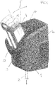
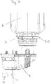
- the device shown for dispensing a flowable medium has a substantially closed housing 1, for example made of plastic, with its rear side 1a either directly or via suitable mounting means can be attached to the wall of a room. Another arrangement, for example placing on the floor, is also possible.
- the flowable medium is dispensed via a schematically illustrated sequence 2. This can be, for example, a flexible hose. However, it is also possible to additionally or alternatively provide a dispensing tap.
- a container receptacle 3 with a receptacle 23 open at the top serves to receive a container 4, which is preferably inserted upside down, ie with its dispensing valve pointing downwards, into the container receptacle 3.
- the container 4 contains the flowable medium, for example a highly concentrated cleaning agent, in particular for a dishwasher.
- other flowable media such as free-flowing powders are also conceivable and possible.
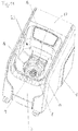
- the container receptacle 3 is pivotally mounted in or on the housing 1, the Fig. 1 the pivoted loading and unloading position for the container 4 shows. Starting from this position, the container receptacle 3 together with the inserted container 4 can then be moved in the direction of the arrow 5 in Fig. 1 in the in Fig. 2 shown, preferably vertical delivery position are pivoted, in which the flowable medium can be removed from the container 4.
- the pivot angle ⁇ need only be less than 45 °, preferably less than 35 °. This means that there is no need for a too wide swivel movement. For the control functions described later, which are triggered by the pivoting movement (controlling the dispensing valve and controlling the holding elements against lifting the container), such a restricted pivoting angle range is easily sufficient.
- the container itself can preferably be essentially cuboid, with flat wall surfaces being formed.
- the cuboid design facilitates correct insertion into the receiving shaft, the inner contour of which is adapted to the outer contour of the container 4. It is sufficient if the container is only partially inserted into the receiving shaft and such as the Fig. 1 and 2nd show protruding from the receiving shaft with at least half its length. This leaves the container and its possible Labeling clearly visible. In addition, it can be easily attacked in the projecting area and thus pivoted together with the container receptacle 3.
- the loading and unloading position shown can be easily inserted from the front, with one-hand operation being sufficient for insertion and pivoting in the direction of arrow 5.
- the delivery valve of the container only in the Fig. 2 shown position is open, but not in the in Fig. 1 shown loading and unloading position. This ensures that the container cannot be removed when the valve is open, making it possible to handle it safely even with highly concentrated chemicals (flowable media).
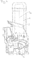
- FIG. 3 The illustration shown again shows the loading and unloading position, the housing wall being hidden so that the interior structure of the housing and the pivot axis 6 are visible.
- the longitudinal central axis 4a of the container runs through the pivot axis 6, which is arranged horizontally and transversely to the longitudinal central axis 4.
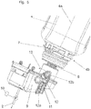
- the Fig. 4 shows the delivery position at which the container receptacle 3 is pivoted in and the container 4 is essentially vertical.
- the Fig. 5 shows the omission of components of the housing 1 and the container receptacle 3, the upside down container 4 in the container neck 4b a dispensing valve 7 is arranged.
- This dispensing valve 7 can be opened by inserting a movable element 8 into the container neck 4b, with which flowable medium in the container can flow out.
- this outflow initially takes place in an intermediate tank 9.
- a drain 2 then leads from this intermediate tank 9 to the outside in order to be able to dispense the flowable medium in a metered manner.
- a pump P in the form of a metering pump can be provided.
- gravity it is also possible to use only one dispensing valve.
- the pump and dispensing valve are generally controlled by an electronic control unit 10 and allow metered dispensing of the flowable medium present in the container 4 or in the intermediate tank 9. In principle, it is also possible to specifically dilute this flowable medium in the housing or in the tank by means of a water supply.
- the intermediate tank the fill level of which can be displayed, enables the containers to be changed without interrupting the dispensing of the medium from the dispenser (buffer tank).
- the Fig. 6 shows in a sectional view details of the discharge valve 7, which is opened by inserting the movable element 8 in the form of a plunger into the container neck 4b, air being able to flow in later.
- Such dispensing valves are basically already known in terms of their structure.
- the Fig. 6 shows the closed position in which the dispensing valve 7 is closed and neither air nor flowable medium can flow.
- Fig. 7 and 8th now show the swiveled-in container, not shown, in the dispensing position.
- the movable element is pushed into the bottle neck 4b in the form of a plunger and thus opens the valve.
- this dispensing valve is in the Fig. 7 and 8th opened, with which flowable medium can flow into the intermediate tank 9.
- the upward arrow indicates how air flows through the discharge valve 7 into the container 4.
- the movable element 8 which is preferably designed as a tappet, is preferably arranged directly on the intermediate tank 9 or is formed integrally thereon. This means that the intermediate tank is moved together with the valve-opening tappet 8.
- the movement in the direction of the longitudinal central axis 4a takes place in a movement-coupled manner with the pivoting movement of the pivotable container receptacle 3.
- the intermediate tank 9 is initially mounted in a linearly displaceable manner in the container receptacle 3 via a slide guide 11 on both sides of the intermediate tank.
- the actual movement coupling with the pivoting position of the container receptacle 3 takes place via a control lever 12, an axis of rotation 12 a of which is fixed to the housing, that is to say mounted on the housing 1 or a component connected to it.
- the opposite axis of rotation 12b is formed on the additional tank 9 or on the plunger 8 which is integrally connected to it.
- dispensing valve 7 is only opened when the container receptacle 3 or the container 4 is pivoted in. In any case, the dispensing valve is closed in the pivoted-out position.
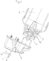
- holding elements 14 are provided, which in Fig. 9 and in Fig. 10 are shown.
- these holding elements horizontally movably mounted holding elements 14 which are biased towards the container neck 4b via a spring 24.
- An annular circumferential groove 15 is formed on the container neck 4b, into which the holding elements 14 can engage, as can be seen in FIG Fig. 10 shows.
- the holding elements 14 are coupled to the pivoting movement of the container receptacle 3 in such a way that in the pivoted loading and unloading position (for example according to FIG Fig. 1 ) the holding elements 14 do not engage in the circumferential groove 15 on the container neck 4b ( Fig. 9 ).
- the container 4 can thus be freely removed or inserted.
- the springs 24 move the holding elements 14 in the direction of the container neck 4b and engage in the circumferential groove 15.
- the container cannot be removed from the container receptacle 3 or the housing 1 in this position. This is important because in this in Fig. 10 position shown, the dispensing valve is open. Highly concentrated, flowable medium would flow out when it was removed.
- a control cam not shown, which is arranged so that the holding elements 14 are pushed back against the spring action when pivoting the container receptacle 3.
- Electromechanically driven variants are also conceivable and possible. It is essential that when the container receptacle is pivoted out, a free insertion or a free removal of the container 4 is possible with the dispensing valve 7 closed, while in the preferably dispensing position the dispensing valve is open and removal of the container 4 is blocked for this.
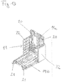
- Fig. 11 the delivery position can be seen in a perspective view, the container 4 not being shown for reasons of clarity. To do this, you can see the intake shaft 23 open at the top.
- the holding elements 14 are extended radially inward and hold the container in the circumferential groove of the container against being lifted or removed.
- the plunger 8 together with the additional tank 9 is raised and opens the dispensing valve 7 when the container is inserted.
- Fig. 11 the multi-part cover 17 is pushed together.
- An electronic control unit 10 and further components of the device, for example also the pump P, can be accommodated in the room 16.
- the Fig. 12 shows a section through the additional tank 9 which is integrally formed with the movable element or plunger 8.
- a suction pipe 18 communicating at the top with the discharge valve 7, not shown, of the container is provided, which extends down to the vicinity of the tank bottom 9a.
- the tank bottom is at the level T B
- the lower end of the suction pipe 18 is at the level H FU .
- the upper end of the suction pipe lies at the level H FO and thus above the additional tank 9 in the area of the tappet 8.
- the air inlet in the plunger 8 is at the height H L significantly higher than the lower edge of the suction pipe H FU .
- the Fig. 13 shows an L-shaped mounting bracket to which the housing 1 can be fastened by inserting, the one L-leg 19a being formed, for example, via fastening openings 20 for wall mounting, while the other L-leg 19b is formed via openings 21 for floor mounting.
- Reinforcements or stiffeners 22 can be provided on the side in order to increase the stability of the L-shaped mounting bracket.
Landscapes
- Health & Medical Sciences (AREA)
- Public Health (AREA)
- Containers And Packaging Bodies Having A Special Means To Remove Contents (AREA)
- Devices For Dispensing Beverages (AREA)
Applications Claiming Priority (1)
| Application Number | Priority Date | Filing Date | Title |
|---|---|---|---|
| ATA50085/2018A AT520911A1 (de) | 2018-01-30 | 2018-01-30 | Vorrichtung zur Abgabe eines fließfähigen Mediums |
Publications (2)
| Publication Number | Publication Date |
|---|---|
| EP3517005A1 EP3517005A1 (de) | 2019-07-31 |
| EP3517005B1 true EP3517005B1 (de) | 2020-08-05 |
Family
ID=65200721
Family Applications (1)
| Application Number | Title | Priority Date | Filing Date |
|---|---|---|---|
| EP19153237.3A Active EP3517005B1 (de) | 2018-01-30 | 2019-01-23 | Vorrichtung zur abgabe eines fliessfähigen mediums |
Country Status (3)
| Country | Link |
|---|---|
| EP (1) | EP3517005B1 (es) |
| AT (1) | AT520911A1 (es) |
| ES (1) | ES2829808T3 (es) |
Families Citing this family (1)
| Publication number | Priority date | Publication date | Assignee | Title |
|---|---|---|---|---|
| WO2021239778A1 (en) * | 2020-05-26 | 2021-12-02 | Details Aps | Fluid dispensing apparatus |
Family Cites Families (3)
| Publication number | Priority date | Publication date | Assignee | Title |
|---|---|---|---|---|
| US878379A (en) * | 1904-02-15 | 1908-02-04 | Robert M Green & Sons | Soda-water fountain. |
| GB9101560D0 (en) * | 1991-01-24 | 1991-03-06 | Boc Group Plc | Fluid delivery system |
| FR2931052B1 (fr) * | 2008-05-13 | 2012-08-03 | Occitane L | Distributeur de liquide a office de rechargement dissimule |
-
2018
- 2018-01-30 AT ATA50085/2018A patent/AT520911A1/de not_active Application Discontinuation
-
2019
- 2019-01-23 EP EP19153237.3A patent/EP3517005B1/de active Active
- 2019-01-23 ES ES19153237T patent/ES2829808T3/es active Active
Also Published As
| Publication number | Publication date |
|---|---|
| EP3517005A1 (de) | 2019-07-31 |
| AT520911A1 (de) | 2019-08-15 |
| ES2829808T3 (es) | 2021-06-02 |
Similar Documents
| Publication | Publication Date | Title |
|---|---|---|
| EP2846927B1 (de) | Tragbares sprühgerät | |
| DE3833961A1 (de) | Geschirrspuelmaschine mit einer zugabekammer fuer reinigungsmittel | |
| DE102013104003B3 (de) | Vorrichtung zum Einbringen einer definierten Menge eines zweiten Pulvers in einen Prozessbehälter | |
| DE102012204540A1 (de) | Starrer Außenbehälter zum aseptischen Flüssigkeitstransport | |
| EP3517005B1 (de) | Vorrichtung zur abgabe eines fliessfähigen mediums | |
| EP0064949A1 (de) | Behälterverschluss für aufsetzbare Abzapfvorrichtungen | |
| EP1180343A2 (de) | Reinigungsgerät | |
| DE60225016T2 (de) | Einen dosierstab bildender spender für flüssige oder gelartige produkte | |
| EP1871539A1 (de) | Spender zur ausgabe flüssiger bis pastöser massen | |
| DE3818238C2 (es) | ||
| DE102015209146B4 (de) | Kaffeevollautomat mit Reinigungsvorrichtung | |
| EP1588773B1 (de) | Spender insbesondere für Seifen- und Creme | |
| EP3305970A1 (de) | Dosiergerät | |
| EP2942107B1 (de) | Entnahmesystem | |
| EP3173006A1 (de) | Dosiergerät | |
| DE3100720A1 (de) | Ventilgesteuerter, vorzugsweise auf einen behaelter aufschraubbarer auslaufstutzen | |
| EP0909722B1 (de) | Befüllgerät zum Befüllen eines Ausgabebehälters und wiederbefüllbarer Ausgabebehälter | |
| DE2705804C3 (de) | Dosiervorrichtung zur Abgabe flüssiger Spül- oder Zusatzmittel | |
| DE4234951A1 (de) | Dosierbehälter für pulverförmige und flüssige Stoffe | |
| DE9422442U1 (de) | Dispenser | |
| DE68923620T2 (de) | Anordnung zum selektiven spenden und mischen von mehreren getränken. | |
| DE102008059642B4 (de) | Dosiervorrichtung | |
| CH386869A (de) | Portioniervorrichtung für Flüssigkeiten | |
| DE3036493C2 (de) | Ausgabevorrichtung für flüssige oder pastöse Güter | |
| DE945538C (de) | Geraet zur Abgabe von Pasten oder Kremen, sowie von gallertartigen und fluessigen Stoffen |
Legal Events
| Date | Code | Title | Description |
|---|---|---|---|
| PUAI | Public reference made under article 153(3) epc to a published international application that has entered the european phase |
Free format text: ORIGINAL CODE: 0009012 |
|
| STAA | Information on the status of an ep patent application or granted ep patent |
Free format text: STATUS: THE APPLICATION HAS BEEN PUBLISHED |
|
| AK | Designated contracting states |
Kind code of ref document: A1 Designated state(s): AL AT BE BG CH CY CZ DE DK EE ES FI FR GB GR HR HU IE IS IT LI LT LU LV MC MK MT NL NO PL PT RO RS SE SI SK SM TR |
|
| AX | Request for extension of the european patent |
Extension state: BA ME |
|
| STAA | Information on the status of an ep patent application or granted ep patent |
Free format text: STATUS: REQUEST FOR EXAMINATION WAS MADE |
|
| 17P | Request for examination filed |
Effective date: 20190916 |
|
| RAX | Requested extension states of the european patent have changed |
Extension state: BA Payment date: 20190916 Extension state: ME |
|
| RBV | Designated contracting states (corrected) |
Designated state(s): AL AT BE BG CH CY CZ DE DK EE ES FI FR GB GR HR HU IE IS IT LI LT LU LV MC MK MT NL NO PL PT RO RS SE SI SK SM TR |
|
| GRAP | Despatch of communication of intention to grant a patent |
Free format text: ORIGINAL CODE: EPIDOSNIGR1 |
|
| STAA | Information on the status of an ep patent application or granted ep patent |
Free format text: STATUS: GRANT OF PATENT IS INTENDED |
|
| RIC1 | Information provided on ipc code assigned before grant |
Ipc: A47K 5/12 20060101AFI20200319BHEP |
|
| INTG | Intention to grant announced |
Effective date: 20200422 |
|
| GRAS | Grant fee paid |
Free format text: ORIGINAL CODE: EPIDOSNIGR3 |
|
| GRAA | (expected) grant |
Free format text: ORIGINAL CODE: 0009210 |
|
| STAA | Information on the status of an ep patent application or granted ep patent |
Free format text: STATUS: THE PATENT HAS BEEN GRANTED |
|
| AK | Designated contracting states |
Kind code of ref document: B1 Designated state(s): AL AT BE BG CH CY CZ DE DK EE ES FI FR GB GR HR HU IE IS IT LI LT LU LV MC MK MT NL NO PL PT RO RS SE SI SK SM TR |
|
| AX | Request for extension of the european patent |
Extension state: BA |
|
| REG | Reference to a national code |
Ref country code: GB Ref legal event code: FG4D Free format text: NOT ENGLISH |
|
| REG | Reference to a national code |
Ref country code: CH Ref legal event code: EP |
|
| REG | Reference to a national code |
Ref country code: AT Ref legal event code: REF Ref document number: 1297527 Country of ref document: AT Kind code of ref document: T Effective date: 20200815 |
|
| REG | Reference to a national code |
Ref country code: DE Ref legal event code: R096 Ref document number: 502019000104 Country of ref document: DE |
|
| REG | Reference to a national code |
Ref country code: IE Ref legal event code: FG4D Free format text: LANGUAGE OF EP DOCUMENT: GERMAN |
|
| REG | Reference to a national code |
Ref country code: CH Ref legal event code: NV Representative=s name: ISLER AND PEDRAZZINI AG, CH |
|
| REG | Reference to a national code |
Ref country code: NL Ref legal event code: FP |
|
| REG | Reference to a national code |
Ref country code: LT Ref legal event code: MG4D |
|
| PG25 | Lapsed in a contracting state [announced via postgrant information from national office to epo] |
Ref country code: PT Free format text: LAPSE BECAUSE OF FAILURE TO SUBMIT A TRANSLATION OF THE DESCRIPTION OR TO PAY THE FEE WITHIN THE PRESCRIBED TIME-LIMIT Effective date: 20201207 Ref country code: GR Free format text: LAPSE BECAUSE OF FAILURE TO SUBMIT A TRANSLATION OF THE DESCRIPTION OR TO PAY THE FEE WITHIN THE PRESCRIBED TIME-LIMIT Effective date: 20201106 Ref country code: NO Free format text: LAPSE BECAUSE OF FAILURE TO SUBMIT A TRANSLATION OF THE DESCRIPTION OR TO PAY THE FEE WITHIN THE PRESCRIBED TIME-LIMIT Effective date: 20201105 Ref country code: SE Free format text: LAPSE BECAUSE OF FAILURE TO SUBMIT A TRANSLATION OF THE DESCRIPTION OR TO PAY THE FEE WITHIN THE PRESCRIBED TIME-LIMIT Effective date: 20200805 Ref country code: FI Free format text: LAPSE BECAUSE OF FAILURE TO SUBMIT A TRANSLATION OF THE DESCRIPTION OR TO PAY THE FEE WITHIN THE PRESCRIBED TIME-LIMIT Effective date: 20200805 Ref country code: HR Free format text: LAPSE BECAUSE OF FAILURE TO SUBMIT A TRANSLATION OF THE DESCRIPTION OR TO PAY THE FEE WITHIN THE PRESCRIBED TIME-LIMIT Effective date: 20200805 Ref country code: BG Free format text: LAPSE BECAUSE OF FAILURE TO SUBMIT A TRANSLATION OF THE DESCRIPTION OR TO PAY THE FEE WITHIN THE PRESCRIBED TIME-LIMIT Effective date: 20201105 Ref country code: LT Free format text: LAPSE BECAUSE OF FAILURE TO SUBMIT A TRANSLATION OF THE DESCRIPTION OR TO PAY THE FEE WITHIN THE PRESCRIBED TIME-LIMIT Effective date: 20200805 |
|
| PG25 | Lapsed in a contracting state [announced via postgrant information from national office to epo] |
Ref country code: RS Free format text: LAPSE BECAUSE OF FAILURE TO SUBMIT A TRANSLATION OF THE DESCRIPTION OR TO PAY THE FEE WITHIN THE PRESCRIBED TIME-LIMIT Effective date: 20200805 Ref country code: PL Free format text: LAPSE BECAUSE OF FAILURE TO SUBMIT A TRANSLATION OF THE DESCRIPTION OR TO PAY THE FEE WITHIN THE PRESCRIBED TIME-LIMIT Effective date: 20200805 Ref country code: LV Free format text: LAPSE BECAUSE OF FAILURE TO SUBMIT A TRANSLATION OF THE DESCRIPTION OR TO PAY THE FEE WITHIN THE PRESCRIBED TIME-LIMIT Effective date: 20200805 Ref country code: IS Free format text: LAPSE BECAUSE OF FAILURE TO SUBMIT A TRANSLATION OF THE DESCRIPTION OR TO PAY THE FEE WITHIN THE PRESCRIBED TIME-LIMIT Effective date: 20201205 |
|
| PG25 | Lapsed in a contracting state [announced via postgrant information from national office to epo] |
Ref country code: SM Free format text: LAPSE BECAUSE OF FAILURE TO SUBMIT A TRANSLATION OF THE DESCRIPTION OR TO PAY THE FEE WITHIN THE PRESCRIBED TIME-LIMIT Effective date: 20200805 Ref country code: EE Free format text: LAPSE BECAUSE OF FAILURE TO SUBMIT A TRANSLATION OF THE DESCRIPTION OR TO PAY THE FEE WITHIN THE PRESCRIBED TIME-LIMIT Effective date: 20200805 Ref country code: CZ Free format text: LAPSE BECAUSE OF FAILURE TO SUBMIT A TRANSLATION OF THE DESCRIPTION OR TO PAY THE FEE WITHIN THE PRESCRIBED TIME-LIMIT Effective date: 20200805 Ref country code: DK Free format text: LAPSE BECAUSE OF FAILURE TO SUBMIT A TRANSLATION OF THE DESCRIPTION OR TO PAY THE FEE WITHIN THE PRESCRIBED TIME-LIMIT Effective date: 20200805 Ref country code: RO Free format text: LAPSE BECAUSE OF FAILURE TO SUBMIT A TRANSLATION OF THE DESCRIPTION OR TO PAY THE FEE WITHIN THE PRESCRIBED TIME-LIMIT Effective date: 20200805 |
|
| REG | Reference to a national code |
Ref country code: DE Ref legal event code: R097 Ref document number: 502019000104 Country of ref document: DE |
|
| PG25 | Lapsed in a contracting state [announced via postgrant information from national office to epo] |
Ref country code: AL Free format text: LAPSE BECAUSE OF FAILURE TO SUBMIT A TRANSLATION OF THE DESCRIPTION OR TO PAY THE FEE WITHIN THE PRESCRIBED TIME-LIMIT Effective date: 20200805 |
|
| REG | Reference to a national code |
Ref country code: ES Ref legal event code: FG2A Ref document number: 2829808 Country of ref document: ES Kind code of ref document: T3 Effective date: 20210602 |
|
| PLBE | No opposition filed within time limit |
Free format text: ORIGINAL CODE: 0009261 |
|
| STAA | Information on the status of an ep patent application or granted ep patent |
Free format text: STATUS: NO OPPOSITION FILED WITHIN TIME LIMIT |
|
| PG25 | Lapsed in a contracting state [announced via postgrant information from national office to epo] |
Ref country code: SK Free format text: LAPSE BECAUSE OF FAILURE TO SUBMIT A TRANSLATION OF THE DESCRIPTION OR TO PAY THE FEE WITHIN THE PRESCRIBED TIME-LIMIT Effective date: 20200805 |
|
| 26N | No opposition filed |
Effective date: 20210507 |
|
| PG25 | Lapsed in a contracting state [announced via postgrant information from national office to epo] |
Ref country code: MC Free format text: LAPSE BECAUSE OF FAILURE TO SUBMIT A TRANSLATION OF THE DESCRIPTION OR TO PAY THE FEE WITHIN THE PRESCRIBED TIME-LIMIT Effective date: 20200805 Ref country code: SI Free format text: LAPSE BECAUSE OF FAILURE TO SUBMIT A TRANSLATION OF THE DESCRIPTION OR TO PAY THE FEE WITHIN THE PRESCRIBED TIME-LIMIT Effective date: 20200805 |
|
| PG25 | Lapsed in a contracting state [announced via postgrant information from national office to epo] |
Ref country code: LU Free format text: LAPSE BECAUSE OF NON-PAYMENT OF DUE FEES Effective date: 20210123 |
|
| REG | Reference to a national code |
Ref country code: BE Ref legal event code: MM Effective date: 20210131 |
|
| PG25 | Lapsed in a contracting state [announced via postgrant information from national office to epo] |
Ref country code: IE Free format text: LAPSE BECAUSE OF NON-PAYMENT OF DUE FEES Effective date: 20210123 |
|
| PG25 | Lapsed in a contracting state [announced via postgrant information from national office to epo] |
Ref country code: BE Free format text: LAPSE BECAUSE OF NON-PAYMENT OF DUE FEES Effective date: 20210131 |
|
| PG25 | Lapsed in a contracting state [announced via postgrant information from national office to epo] |
Ref country code: CY Free format text: LAPSE BECAUSE OF FAILURE TO SUBMIT A TRANSLATION OF THE DESCRIPTION OR TO PAY THE FEE WITHIN THE PRESCRIBED TIME-LIMIT Effective date: 20200805 |
|
| P01 | Opt-out of the competence of the unified patent court (upc) registered |
Effective date: 20230612 |
|
| P02 | Opt-out of the competence of the unified patent court (upc) changed |
Effective date: 20230621 |
|
| PG25 | Lapsed in a contracting state [announced via postgrant information from national office to epo] |
Ref country code: HU Free format text: LAPSE BECAUSE OF FAILURE TO SUBMIT A TRANSLATION OF THE DESCRIPTION OR TO PAY THE FEE WITHIN THE PRESCRIBED TIME-LIMIT; INVALID AB INITIO Effective date: 20190123 |
|
| PG25 | Lapsed in a contracting state [announced via postgrant information from national office to epo] |
Ref country code: MK Free format text: LAPSE BECAUSE OF FAILURE TO SUBMIT A TRANSLATION OF THE DESCRIPTION OR TO PAY THE FEE WITHIN THE PRESCRIBED TIME-LIMIT Effective date: 20200805 |
|
| PG25 | Lapsed in a contracting state [announced via postgrant information from national office to epo] |
Ref country code: MT Free format text: LAPSE BECAUSE OF FAILURE TO SUBMIT A TRANSLATION OF THE DESCRIPTION OR TO PAY THE FEE WITHIN THE PRESCRIBED TIME-LIMIT Effective date: 20200805 |
|
| PGFP | Annual fee paid to national office [announced via postgrant information from national office to epo] |
Ref country code: NL Payment date: 20250127 Year of fee payment: 7 |
|
| PGFP | Annual fee paid to national office [announced via postgrant information from national office to epo] |
Ref country code: DE Payment date: 20250129 Year of fee payment: 7 |
|
| PGFP | Annual fee paid to national office [announced via postgrant information from national office to epo] |
Ref country code: ES Payment date: 20250210 Year of fee payment: 7 |
|
| PGFP | Annual fee paid to national office [announced via postgrant information from national office to epo] |
Ref country code: CH Payment date: 20250201 Year of fee payment: 7 Ref country code: AT Payment date: 20250127 Year of fee payment: 7 |
|
| PGFP | Annual fee paid to national office [announced via postgrant information from national office to epo] |
Ref country code: FR Payment date: 20250127 Year of fee payment: 7 |
|
| PGFP | Annual fee paid to national office [announced via postgrant information from national office to epo] |
Ref country code: IT Payment date: 20250122 Year of fee payment: 7 Ref country code: GB Payment date: 20250121 Year of fee payment: 7 |
|
| PG25 | Lapsed in a contracting state [announced via postgrant information from national office to epo] |
Ref country code: TR Free format text: LAPSE BECAUSE OF FAILURE TO SUBMIT A TRANSLATION OF THE DESCRIPTION OR TO PAY THE FEE WITHIN THE PRESCRIBED TIME-LIMIT Effective date: 20200805 |
|
| REG | Reference to a national code |
Ref country code: CH Ref legal event code: U11 Free format text: ST27 STATUS EVENT CODE: U-0-0-U10-U11 (AS PROVIDED BY THE NATIONAL OFFICE) Effective date: 20260201 |