EP3512648B2 - Verfahren zur herstellung von tiefbettfelgen, tiefbettfelge und fahrzeugrad damit für nutzfahrzeuge - Google Patents
Verfahren zur herstellung von tiefbettfelgen, tiefbettfelge und fahrzeugrad damit für nutzfahrzeuge Download PDFInfo
- Publication number
- EP3512648B2 EP3512648B2 EP17772772.4A EP17772772A EP3512648B2 EP 3512648 B2 EP3512648 B2 EP 3512648B2 EP 17772772 A EP17772772 A EP 17772772A EP 3512648 B2 EP3512648 B2 EP 3512648B2
- Authority
- EP
- European Patent Office
- Prior art keywords
- rim
- drop centre
- wall thickness
- steep
- tapered bead
- Prior art date
- Legal status (The legal status is an assumption and is not a legal conclusion. Google has not performed a legal analysis and makes no representation as to the accuracy of the status listed.)
- Active
Links
Images

Classifications
-
- B—PERFORMING OPERATIONS; TRANSPORTING
- B21—MECHANICAL METAL-WORKING WITHOUT ESSENTIALLY REMOVING MATERIAL; PUNCHING METAL
- B21D—WORKING OR PROCESSING OF SHEET METAL OR METAL TUBES, RODS OR PROFILES WITHOUT ESSENTIALLY REMOVING MATERIAL; PUNCHING METAL
- B21D5/00—Bending sheet metal along straight lines, e.g. to form simple curves
- B21D5/06—Bending sheet metal along straight lines, e.g. to form simple curves by drawing procedure making use of dies or forming-rollers, e.g. making profiles
- B21D5/10—Bending sheet metal along straight lines, e.g. to form simple curves by drawing procedure making use of dies or forming-rollers, e.g. making profiles for making tubes
- B21D5/12—Bending sheet metal along straight lines, e.g. to form simple curves by drawing procedure making use of dies or forming-rollers, e.g. making profiles for making tubes making use of forming-rollers
-
- B—PERFORMING OPERATIONS; TRANSPORTING
- B21—MECHANICAL METAL-WORKING WITHOUT ESSENTIALLY REMOVING MATERIAL; PUNCHING METAL
- B21D—WORKING OR PROCESSING OF SHEET METAL OR METAL TUBES, RODS OR PROFILES WITHOUT ESSENTIALLY REMOVING MATERIAL; PUNCHING METAL
- B21D53/00—Making other particular articles
- B21D53/26—Making other particular articles wheels or the like
- B21D53/30—Making other particular articles wheels or the like wheel rims
-
- B—PERFORMING OPERATIONS; TRANSPORTING
- B60—VEHICLES IN GENERAL
- B60B—VEHICLE WHEELS; CASTORS; AXLES FOR WHEELS OR CASTORS; INCREASING WHEEL ADHESION
- B60B21/00—Rims
- B60B21/02—Rims characterised by transverse section
- B60B21/026—Rims characterised by transverse section the shape of rim well
-
- B—PERFORMING OPERATIONS; TRANSPORTING
- B60—VEHICLES IN GENERAL
- B60B—VEHICLE WHEELS; CASTORS; AXLES FOR WHEELS OR CASTORS; INCREASING WHEEL ADHESION
- B60B23/00—Attaching rim to wheel body
-
- B—PERFORMING OPERATIONS; TRANSPORTING
- B60—VEHICLES IN GENERAL
- B60B—VEHICLE WHEELS; CASTORS; AXLES FOR WHEELS OR CASTORS; INCREASING WHEEL ADHESION
- B60B3/00—Disc wheels, i.e. wheels with load-supporting disc body
- B60B3/002—Disc wheels, i.e. wheels with load-supporting disc body characterised by the shape of the disc
-
- B—PERFORMING OPERATIONS; TRANSPORTING
- B60—VEHICLES IN GENERAL
- B60B—VEHICLE WHEELS; CASTORS; AXLES FOR WHEELS OR CASTORS; INCREASING WHEEL ADHESION
- B60B3/00—Disc wheels, i.e. wheels with load-supporting disc body
- B60B3/04—Disc wheels, i.e. wheels with load-supporting disc body with a single disc body not integral with rim, i.e. disc body and rim being manufactured independently and then permanently attached to each other in a second step, e.g. by welding
- B60B3/041—Disc wheels, i.e. wheels with load-supporting disc body with a single disc body not integral with rim, i.e. disc body and rim being manufactured independently and then permanently attached to each other in a second step, e.g. by welding characterised by the attachment of rim to wheel disc
- B60B3/044—Disc wheels, i.e. wheels with load-supporting disc body with a single disc body not integral with rim, i.e. disc body and rim being manufactured independently and then permanently attached to each other in a second step, e.g. by welding characterised by the attachment of rim to wheel disc characterised by cross-sectional details of the attachment, e.g. the profile
-
- B—PERFORMING OPERATIONS; TRANSPORTING
- B60—VEHICLES IN GENERAL
- B60B—VEHICLE WHEELS; CASTORS; AXLES FOR WHEELS OR CASTORS; INCREASING WHEEL ADHESION
- B60B2310/00—Manufacturing methods
- B60B2310/20—Shaping
- B60B2310/224—Shaping by rolling
-
- B—PERFORMING OPERATIONS; TRANSPORTING
- B60—VEHICLES IN GENERAL
- B60B—VEHICLE WHEELS; CASTORS; AXLES FOR WHEELS OR CASTORS; INCREASING WHEEL ADHESION
- B60B2360/00—Materials; Physical forms thereof
- B60B2360/10—Metallic materials
- B60B2360/102—Steel
-
- B—PERFORMING OPERATIONS; TRANSPORTING
- B60—VEHICLES IN GENERAL
- B60B—VEHICLE WHEELS; CASTORS; AXLES FOR WHEELS OR CASTORS; INCREASING WHEEL ADHESION
- B60B3/00—Disc wheels, i.e. wheels with load-supporting disc body
- B60B3/14—Attaching disc body to hub ; Wheel adapters
- B60B3/16—Attaching disc body to hub ; Wheel adapters by bolts or the like
Definitions
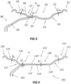
- the invention relates to a method for producing one-piece, substantially rotationally symmetrical 15° drop centre rims for vehicle wheels of commercial vehicles, having a plurality of material forming steps, in which the drop centre rim receives as zones at least one inner rim flange and one outer rim flange, an inner steep-taper bead seat and an outer steep-taper bead seat and a rim drop centre with a drop centre base, an inner drop centre flank and an outer drop centre flank between the steep-taper bead seats, wherein one of the zones is provided as a disc attachment region for a wheel disc, and wherein the material forming steps comprise at least one profiling step, and, by means of at least one of the material forming steps, the material thickness of the drop centre rim receives at least one partial zone with a reduced wall thickness relative to the other zones.
- the invention furthermore also relates to a drop centre rim for vehicle wheels of commercial vehicles, having a plurality of zones formed on the drop centre rim, which form an inner rim flange and an outer rim flange, an inner steep-taper bead seat and an outer steep-taper bead seat and a rim drop centre with a drop centre base, an inner drop centre flank and an outer drop centre flank between the steep-taper bead seats, wherein one of the zones is provided as a disc attachment region for a wheel disc, and the drop centre rim has at least one partial zone with a reduced wall thickness relative to the other zones.
- the invention furthermore also relates to a vehicle wheel for commercial vehicles, having a substantially rotationally symmetrical drop centre rim and a wheel disc that has stud holes, arranged in the interior of the drop centre rim, for fastening the vehicle wheel on a vehicle, and is connected, in particular welded, to the drop centre rim in the disc attachment region.
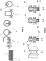
- corresponding commercial vehicle wheels are provided with an external valve, i.e. the valve is situated on the vehicle wheel in a space outside the wheel disc, between the outer steep steep-tapered bead seat of the rim and the outer surface of the wheel disc, which is shaped appropriately to create sufficient free space for disc brakes on the commercial vehicle.
- the basic structure and required dimensions of corresponding drop centre rims with 15° steep-tapered bead seats are standardized by ETRTO, for example.
- the basic design requirements on commercial vehicle wheels are maximum strength with minimum weight and low production costs.
- DE 199 24 062 A1 proposes to clamp the rim blank (sheet metal ring) used to produce the rim on a cylindrical rolling mandrel before the rim profile is formed to shape by means of profiled rollers, and then to extend the blank axially by means of a spinning roller, thereby producing partial zones with a defined wall thickness reduction.
- the rim profile was then formed to final shape on a separate profiling machine.
- DE 20 2005 021 881 U1 describes a device and a method that can be used on said device for producing rims of optimized weight, in which a spinning station is used to conically expand the rim blank, whereupon the wall thickness of the rim blank is then varied at the expanded sides of the rim blank by means of flow turning in a flow turning station following the spinning station before the end profiling is performed.
- a drop centre rim for vehicle wheels having a plurality of zones, which form an inner rim flange and an outer rim flange, an inner steep-tapered bead seat and an outer steep-tapered bead seat and a rim drop centre with a drop centre base, an inner drop centre flank and an outer drop centre flank between the steep-tapered bead seats, wherein one of the zones is provided as a disc attachment region for a wheel disc, the drop centre rim has at least one partial zone with a reduced wall thickness relative to the other zones, and the steep-tapered bead seats are having an upper, radial outer side surface and a lower, radial inner side surface, wherein at least one of the steep-tapered bead seats has a section with a wall thickness reduction.
- the invention proposes a method in which the reduction in the wall thickness in the at least one partial zone takes place during the profiling step of at least one of the steep-tapered bead seats, and the steep-tapered bead seat receives a section with a wall thickness reduction of more than 20% relative to the wall thickness in the zone provided for the disc attachment region.
- the selective production of the wall thickness reduction in one of the profiling steps preferably in the first profiling step after the slanting of the ring ends of the rim blank in a pre-profiling step, has the advantage that there is no need for an additional station or machine, and hence the production time can be shortened.
- only the outer steep-tapered bead seat and/or the inner steep-tapered bead seat receive/receives a wall thickness reduction of more than 20% relative to the wall thickness in the disc attachment region.
- the reduced wall thicknesses in both steep-tapered bead seats which are achieved according to the invention can be of the same magnitude or different, and the reduced wall thickness produced on the drop centre rim can also be the same magnitude as or different from the reduced wall thickness in the region of one steep-tapered bead seat or both steep-tapered bead seats.
- the profiling of the sections with a reduction in the wall thickness in the steep-tapered bead seat/s is performed in a direction towards the nearest rim flange.
- the sections with a wall thickness reduction on the finished vehicle wheel have a conical profile and receive a larger reduction in thickness on the side closer to the drop centre base than on the side closer to the rim flange.
- the abovementioned object is achieved, in the case of a vehicle wheel, by virtue of the fact that at least one of the steep-tapered bead seats has a section with a wall thickness reduction of more than 20% relative to the wall thickness in the zone provided as a disc attachment region.
- the selective wall thickness reduction in at least one of the steep-tapered bead seats in a profiling step offers the advantages mentioned above while simultaneously reducing the weight.
- both bead seats have a wall thickness reduction of more than 20% relative to the zone provided for the disc attachment region or, more advantageously, both bead seats have a wall thickness reduction of more than 20% relative to the zone provided for the disc attachment region.
- the outer steep-tapered bead seat and the inner steep-tapered bead seat and, in addition, the rim drop centre to have a wall thickness reduction of more than 20% relative to the wall thickness in the zone provided for the disc attachment region.
- zones can likewise receive a wall thickness reduction relative to the wall thickness in the disc attachment region, but this is then preferably less than the wall thickness reduction according to the invention in the partial zones mentioned, with the result that the smallest wall thickness in absolute terms is produced or exists in one of the two steep-tapered bead seats or in both steep-tapered bead seats and optionally in the drop centre. 0.5° and 1.5°.
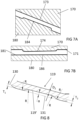
- the sections with a wall thickness reduction of more than 20% relative to the wall thickness in the disc attachment region have a conical profile and have a larger reduction in thickness, i.e. a smaller wall thickness, on the side closer to the drop centre base, i.e. closer to the drop centre, than on the side closer to the rim flange (closer to the adjacent rim flange), wherein the slope angle in the conical region is preferably between 0.5° and 1.5°.
- the maximum wall thickness reduction in the sections with a wall thickness reduction relative to an initial wall thickness of the initial sheet used to produce the drop centre rim is between 20% and 40%, preferably between 25% and 35%, and in particular between 28% and 32%, based on the initial wall thickness.
- the sections with a wall thickness reduction preferably merge into the zones immediately adjoining them by means of respective radii and an inflection point formed between the radii.
- the drop centre rim has an upper side and a lower side, wherein the wall thickness reduction is formed in the steep-tapered bead seats on the lower side.
- the upper side of the 15° steep-tapered bead seats forms the bearings surface for the sealing bead on the tyre on the drop centre rim and then remains flat.
- an additional profiling step (indicated by 2.5 in Figure 2 ) to be provided.
- a corresponding additional profiling step could be advantageous, for example, if the drop centre rim is supposed to receive a reduction in thickness both in both steep-tapered bead seats and in the rim drop centre, as explained with reference to Figure 5 .
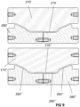
- Figure 9 therefore shows separate tools for producing the reductions in thickness in the steep-tapered bead seats, on the one hand, and in the rim drop centre, on the other hand, in separate profiling steps.
- the tools 270', 280' shown above in Figure 9 could be used in profiling step 2.2, for example, wherein, in this profiling step, only the reduction in material thickness in the region of the rim drop centre is produced by means of the tools 270', 280'. Only tool 270' therefore has a corresponding raised portion 274' on the surface contour thereof. Only in the second profiling step (2.5 in Figure 2 ) would the reductions in thickness then be produced in the region of the two steep-tapered bead seats.
- the tool 280" used for this purpose in the lower region of Figure 9 correspondingly has raised portions 284", 285", whereas the rim drop centre does not undergo any further reduction in thickness or change in shape in this profiling step since the mutually opposite central regions 276", 286" are each flat.
- the reductions in thickness in both steep-tapered bead seats are preferably performed simultaneously using the same tool.
- the additional reduction in thickness in the region of the rim drop centre if such a reduction is provided, can be produced by means of a tool in one method step or by means of different tools in different method steps, as explained.
- the respective selectively produced reduced wall thicknesses can be identical to each other or different from each other and it is sufficient if the minimum wall thickness in the regions of reduced wall thickness is smaller by the required value than in the region of the disc attachment region.
- the wall thickness in the disc attachment region can correspond to the initial thickness of the sheet blank used to produce the blank. However, a smaller wall thickness could also be present, especially if corresponding regions are subsequently mechanically machined.
Landscapes
- Engineering & Computer Science (AREA)
- Mechanical Engineering (AREA)
- Shaping Metal By Deep-Drawing, Or The Like (AREA)
- Tires In General (AREA)
- Forging (AREA)
Claims (11)
- Verfahren zur Herstellung von einteiligen, im Wesentlichen rotationssymmetrischen Tiefbettfelgen für Fahrzeugräder von Nutzfahrzeugen, mit mehreren Materialumformungsschritten, in welchen die Tiefbettfelge als Zonen zumindest ein inneres Felgenhorn (11; 111) und ein äußeres Felgenhorn (20; 120), eine innere 15° Steilschulter (12; 112) und eine äußere 15° Steilschulter (19; 119) sowie ein Felgentiefbett mit Tiefbettboden (13; 113), innerer Bettflanke (14; 114) und äußerer Bettflanke (15; 115) zwischen den Steilschultern erhält, wobei eine der Zonen als Schüsselanbindungsbereich (A) für eine Radschüssel vorgesehen ist, und wobei die Materialumformungsschritte wenigstens einen Profilierungsschritt umfassen und mittels wenigstens eines der Materialumformungsschritte die Materialdicke der Tiefbettfelge wenigstens eine Teilzone mit gegenüber den anderen Zonen verringerter Wanddicke erhält, wobei die Reduzierung der Wanddicke in der wenigstens einen Teilzone beim Profilierungsschritt wenigstens einer der 15° Steilschultern (12, 19; 112, 119) stattfindet und die Steilschulter (12, 19; 112, 119) einen Abschnitt mit einer Wanddickenreduzierung von mehr als 20% gegenüber der Wanddicke (D) in der für den Schüsselanbindungsbereich (A) vorgesehenen Zone erhält, und wobei die Abschnitte mit der Wanddickenreduzierung konisch verlaufen und tiefbettbodenseitig eine größere Dickenreduzierung erhalten als felgenhornseitig.
- Verfahren nach Anspruch 1, dadurch gekennzeichnet, dass ausschließlich die äußere Steilschulter (19; 19) und/oder die innere Steilschulter (12; 112) eine Wanddickenreduzierung von mehr als 20% gegenüber der Wanddicke im Schüsselanbindungsbereich erhält/erhalten, oder dass ausschließlich die äußere Steilschulter (119) und die innere Steilschulter (112) sowie das Felgentiefbett (113) eine Wanddickenreduzierung von mehr als 20% gegenüber der Wanddicke in der für den Schüsselanbindungsbereich vorgesehenen Zone erhalten.
- Verfahren nach einem der vorhergehenden Ansprüche, dadurch gekennzeichnet, dass die Profilierung der Abschnitte mit Reduzierung der Wanddicke in der/den Steilschulter/n in Richtung auf das nächstgelegene Felgenhorn zu vorgenommen wird.
- Tiefbettfelge für Fahrzeugräder von Nutzfahrzeugen, mit mehreren Zonen, die ein inneres Felgenhorn (11; 111) und ein äußeres Felgenhorn (20; 120), eine innere 15° Steilschulter (12; 112) und eine äußere 15° Steilschulter (19; 119) sowie ein Felgentiefbett mit Tiefbettboden (13; 113), innerer Bettflanke (14; 114) und äußerer Bettflanke (15; 115) zwischen den Steilschultern bilden, wobei eine der Zonen als Schüsselanbindungsbereich (A) für eine Radschüssel vorgesehen ist und die Tiefbettfelge wenigstens eine Teilzone mit gegenüber den anderen Zonen verringerter Wanddicke aufweist, und die 15° Steilschultern (12, 19; 112, 119) eine obere, radial äußere Seitenfläche haben (110") und eine untere, radial innere Seitenfläche (110'), wobei wenigstens eine der 15° Steilschultern (12, 19; 112, 119) einen Abschnitt mit einer Wanddickenreduzierung, erzeugt durch eine Vertiefung an der unteren, radial inneren Seitenfläche (110'), von mehr als 20% gegenüber der Wanddicke (D) in der als Schüsselanbindungsbereich (A) vorgesehenen Zone aufweist, und wobei die Abschnitte mit der Wanddickenreduzierung konisch verlaufen und tiefbettbodenseitig eine größere Dickenreduzierung erhalten als felgenhornseitig.
- Tiefbettfelge nach Anspruch 4, dadurch gekennzeichnet, dass ausschließlich eine Felgenschulter, oder ausschließlich beide Felgenschultern (12, 19), eine Wanddickenreduzierung, erzeugt durch eine Vertiefung an der Oberfläche, von mehr als 20% gegenüber der für den Schüsselanbindungsbereich (A) vorgesehenen Zone aufweisen, oder dass ausschließlich die äußere Steilschulter (119) und die innere Steilschulter (112) sowie das Felgentiefbett (113) eine Wanddickenreduzierung, erzeugt durch eine Vertiefung an der Oberfläche, von mehr als 20% gegenüber der Wanddicke in der für den Schüsselanbindungsbereich (A) vorgesehenen Zone aufweisen.
- Tiefbettfelge nach einem der vorhergehenden Ansprüche,
dadurch gekennzeichnet, dass der Schrägenwinkel (α) im konischen Bereich zwischen 0,5° und 1,5° liegt. - Tiefbettfelge nach einem der vorhergehenden Ansprüche,
dadurch gekennzeichnet, dass die maximale Wanddickenreduzierung (D1, D2) in den Abschnitten mit Wanddickenreduzierung relativ zu einer Ausgangswanddicke des zur Herstellung der Tiefbettfelge verwendeten Ausgangsblechs zwischen 20% und 40%, vorzugsweise zwischen 25% und 35%, und insbesondere zwischen 28% und 32% bezogen auf die Ausgangswanddicke beträgt. - Tiefbettfelge nach einem der Ansprüche 4 bis 7, dadurch gekennzeichnet, dass die Abschnitte mit Wanddickenreduzierung in die hieran unmittelbar angrenzenden Zonen jeweils mittels Radien (R) und zwischen den Radien ausgebildetem Wendepunkt übergehen.
- Tiefbettfelge gemäß einem der Ansprüche 4 bis 8, gekennzeichnet durch einen Übergangsabschnitt zwischen Felgentiefbett und einer der Steilschultern zum Vorsehen eines Ventillochs im Übergangsabschnitt.
- Verfahren nach einem der Ansprüche 1 bis 3, gekennzeichnet durch einen Übergangsabschnitt zwischen Felgentiefbett und einer der Steilschultern zum Vorsehen eines Ventillochs im Übergangsabschnitt.
- Fahrzeugrad für Nutzfahrzeuge, mit einer im Wesentlichen rotationssymmetrischen Tiefbettfelge und einer im Innern der Tiefbettfelge angeordneten, Bolzenlöcher zur Befestigung des Fahrzeugrades an einem Fahrzeug aufweisenden Radschüssel, die im Schüsselanbindungsbereich (A) an die Felge angeschlossen ist, insbesondere angeschweißt ist, dadurch gekennzeichnet, dass die Tiefbettfelge gemäß einem der Ansprüche 4 bis 9 ausgebildet ist.
Applications Claiming Priority (2)
| Application Number | Priority Date | Filing Date | Title |
|---|---|---|---|
| DE102016117510.2A DE102016117510A1 (de) | 2016-09-16 | 2016-09-16 | Verfahren zur Herstellung von Steilschulterfelgen, Steilschulterfelge und Fahrzeugrad hiermit für Nutzfahrzeuge |
| PCT/IB2017/055596 WO2018051282A1 (en) | 2016-09-16 | 2017-09-15 | Method for producing drop centre rims, drop centre rim and vehicle wheel therewith for commercial vehicles |
Publications (3)
| Publication Number | Publication Date |
|---|---|
| EP3512648A1 EP3512648A1 (de) | 2019-07-24 |
| EP3512648B1 EP3512648B1 (de) | 2022-11-02 |
| EP3512648B2 true EP3512648B2 (de) | 2025-07-02 |
Family
ID=59969201
Family Applications (1)
| Application Number | Title | Priority Date | Filing Date |
|---|---|---|---|
| EP17772772.4A Active EP3512648B2 (de) | 2016-09-16 | 2017-09-15 | Verfahren zur herstellung von tiefbettfelgen, tiefbettfelge und fahrzeugrad damit für nutzfahrzeuge |
Country Status (8)
| Country | Link |
|---|---|
| US (1) | US11633979B2 (de) |
| EP (1) | EP3512648B2 (de) |
| JP (1) | JP7168553B2 (de) |
| KR (1) | KR102453079B1 (de) |
| CN (1) | CN109715311B (de) |
| BR (1) | BR112019002680B1 (de) |
| DE (1) | DE102016117510A1 (de) |
| WO (1) | WO2018051282A1 (de) |
Families Citing this family (4)
| Publication number | Priority date | Publication date | Assignee | Title |
|---|---|---|---|---|
| DE102016117510A1 (de) | 2016-09-16 | 2018-03-22 | Maxion Wheels Germany Holding Gmbh | Verfahren zur Herstellung von Steilschulterfelgen, Steilschulterfelge und Fahrzeugrad hiermit für Nutzfahrzeuge |
| CN112319129A (zh) * | 2020-02-27 | 2021-02-05 | 浙江航通机械制造股份有限公司 | 一种轻量化汽车轮辋结构及制造方法 |
| CN113173034B (zh) | 2021-06-10 | 2024-07-05 | 蒂森克虏伯钢铁(北京)有限公司 | 用于商用车辆的超轻量化钢制车轮 |
| DE102024107025A1 (de) | 2024-03-12 | 2025-09-18 | Accuride Wheels Solingen Gmbh | Fahrzeugrad für ein Nutzfahrzeug |
Family Cites Families (24)
| Publication number | Priority date | Publication date | Assignee | Title |
|---|---|---|---|---|
| JPH01245932A (ja) * | 1988-03-26 | 1989-10-02 | Honda Motor Co Ltd | 高精度リムの製造方法 |
| US4962587A (en) * | 1989-04-21 | 1990-10-16 | Kelsey-Hayes Company | Method of making a wheel rim |
| US5579578A (en) * | 1993-10-27 | 1996-12-03 | Hayes Wheels International, Inc. | Method for producing a rim for a vechicle wheel |
| ES2144671T3 (es) | 1995-07-25 | 2000-06-16 | Michelin & Cie | Rueda de vehiculo utilitario con valvula que desemboca en el exterior del disco. |
| JPH10137885A (ja) | 1996-11-06 | 1998-05-26 | Topy Ind Ltd | ホイール用環状リム素材の転圧方法 |
| JPH1159107A (ja) * | 1997-08-28 | 1999-03-02 | Topy Ind Ltd | 大中型チューブレスホイール用リム |
| JP4152035B2 (ja) | 1999-03-09 | 2008-09-17 | トピー工業株式会社 | 不均一板厚リムの製造方法 |
| DE19924062A1 (de) | 1999-05-26 | 1999-12-09 | Leico Werkzeugmaschb Gmbh & Co | Verfahren und Vorrichtung zum Drückwalzen |
| FR2816532B1 (fr) | 2000-11-13 | 2003-01-24 | Michelin Soc Tech | Procede de fabrication d'une jante de roue de vehicule |
| FR2819741A1 (fr) * | 2001-01-23 | 2002-07-26 | Michelin Soc Tech | Jante de roue en tole d'acier a profil optimise |
| DE10228588A1 (de) * | 2002-06-26 | 2004-01-15 | Hayes Lemmerz Holding Gmbh | Verfahren zur Herstellung einer Felgenvorform und Felge |
| JP4188029B2 (ja) * | 2002-08-23 | 2008-11-26 | 横浜ゴム株式会社 | タイヤ用ホイール |
| DE10248356A1 (de) * | 2002-10-17 | 2004-04-29 | Wf-Maschinenbau Und Blechformtechnik Gmbh & Co Kg | Verfahren und Vorrichtung zur Herstellung einer gewichtsoptimierten Luftreifenfelge |
| JP4076451B2 (ja) * | 2003-01-28 | 2008-04-16 | トピー工業株式会社 | 不等厚リム用リム素材、不等厚リム、不等厚リムの製造方法 |
| NL1026796C2 (nl) | 2004-08-06 | 2006-02-07 | Fontijne Grotnes B V | Werkwijze en inrichting voor het door middel van koude vervorming vervaardigen van een velgring. |
| NL1031775C2 (nl) * | 2006-05-09 | 2007-11-12 | Fontijne Grotnes B V | Werkwijze en inrichting voor het bewerken van een voorvorm voor een velg, alsmede velg. |
| WO2009057128A2 (en) | 2007-11-01 | 2009-05-07 | Wheels India Limited | Vehicle wheels having non-constant thickness rims |
| WO2010140249A1 (ja) | 2009-06-05 | 2010-12-09 | 中央精機株式会社 | 自動車用ホイール |
| EP2374631B1 (de) * | 2010-04-09 | 2013-03-20 | Iochpe-Maxion S.A. | Stahlrad für schlauchlose Reifen |
| DE102010056419C5 (de) | 2010-12-23 | 2017-12-14 | Kronprinz Gmbh | Fahrzeugrad für Nutzfahrzeuge |
| CN203318027U (zh) * | 2013-05-08 | 2013-12-04 | 浙江金固股份有限公司 | 一种高强度轻量化车轮轮辋 |
| CN104249600A (zh) * | 2014-03-18 | 2014-12-31 | 浙江金固股份有限公司 | 一种轮辐轮辋双旋压车轮 |
| KR101625375B1 (ko) * | 2016-02-19 | 2016-05-30 | 주식회사 지티물류 | 림부가 개선된 차량용 방진휠 |
| DE102016117510A1 (de) | 2016-09-16 | 2018-03-22 | Maxion Wheels Germany Holding Gmbh | Verfahren zur Herstellung von Steilschulterfelgen, Steilschulterfelge und Fahrzeugrad hiermit für Nutzfahrzeuge |
-
2016
- 2016-09-16 DE DE102016117510.2A patent/DE102016117510A1/de not_active Withdrawn
-
2017
- 2017-09-15 JP JP2019510779A patent/JP7168553B2/ja active Active
- 2017-09-15 CN CN201780057149.5A patent/CN109715311B/zh not_active Expired - Fee Related
- 2017-09-15 BR BR112019002680-0A patent/BR112019002680B1/pt not_active IP Right Cessation
- 2017-09-15 EP EP17772772.4A patent/EP3512648B2/de active Active
- 2017-09-15 WO PCT/IB2017/055596 patent/WO2018051282A1/en not_active Ceased
- 2017-09-15 US US16/332,642 patent/US11633979B2/en active Active
- 2017-09-15 KR KR1020197005553A patent/KR102453079B1/ko active Active
Also Published As
| Publication number | Publication date |
|---|---|
| US11633979B2 (en) | 2023-04-25 |
| DE102016117510A1 (de) | 2018-03-22 |
| WO2018051282A1 (en) | 2018-03-22 |
| KR102453079B1 (ko) | 2022-10-07 |
| KR20190051953A (ko) | 2019-05-15 |
| EP3512648A1 (de) | 2019-07-24 |
| JP7168553B2 (ja) | 2022-11-09 |
| BR112019002680A2 (pt) | 2019-05-14 |
| US20210283949A1 (en) | 2021-09-16 |
| EP3512648B1 (de) | 2022-11-02 |
| CN109715311A (zh) | 2019-05-03 |
| CN109715311B (zh) | 2021-08-13 |
| BR112019002680B1 (pt) | 2023-01-17 |
| JP2019529207A (ja) | 2019-10-17 |
Similar Documents
| Publication | Publication Date | Title |
|---|---|---|
| EP3512648B2 (de) | Verfahren zur herstellung von tiefbettfelgen, tiefbettfelge und fahrzeugrad damit für nutzfahrzeuge | |
| US20170232498A1 (en) | Forming methods of one-piece wheels without welding seam made of metal sheets | |
| US6183047B1 (en) | Wheel rim top cover | |
| CN104385847B (zh) | 一种三片复合式旋压轮毂及其制造方法 | |
| CN111266808A (zh) | 一种等厚钢板加工汽车车轮钢圈的方法 | |
| CN101982291A (zh) | 工程车车轮的制造方法 | |
| CN106660388A (zh) | 用于辐板式车轮的车轮辐板 | |
| US10247289B2 (en) | Component with internal and external teeth and method for manufacturing component | |
| US20080252136A1 (en) | Wheels of Single Component Construction and Method of Making Same | |
| US20040107576A1 (en) | Method of manufacturing alloy rim for automobile | |
| US20040124695A1 (en) | Sheet-steel wheel rim with optimized profile | |
| CN110369963B (zh) | 整体式车轮的制备方法 | |
| US12447770B2 (en) | Vehicle wheel disc, vehicle wheel including such a wheel disc and method for producing such a wheel disc and vehicle wheel | |
| US3364550A (en) | Method of manufacturing wheel rims | |
| US6298702B1 (en) | Method for making seamless wheel rims | |
| JP2000312940A (ja) | ギア部品及びその成形方法 | |
| JPS5915733B2 (ja) | 車輛用合金ホイ−ルの製造方法 | |
| US20230278361A1 (en) | Vehicle wheel disc, vehicle wheel including such a wheel disc and method for producing such a wheel disc and vehicle wheel | |
| US20230278362A1 (en) | Vehicle wheel disc, vehicle wheel including such a wheel disc and method for producing such a wheel disc and vehicle wheel | |
| US20230278363A1 (en) | Vehicle wheel disc, vehicle wheel including such a wheel disc and method for producing such a wheel disc and vehicle wheel | |
| CN103079839A (zh) | 车辆用车轮 | |
| US6584824B1 (en) | Apparatus for producing a vehicle wheel rim | |
| US20230278364A1 (en) | Vehicle wheel disc, vehicle wheel including such a wheel disc and method for producing such a wheel disc and vehicle wheel | |
| US7490406B2 (en) | Bicycle wheel rim with internally reinforced spoke seats and method for producing them | |
| US787801A (en) | Method of fastening wheel-tires to the wheel-bodies in wheels for railway-vehicles. |
Legal Events
| Date | Code | Title | Description |
|---|---|---|---|
| STAA | Information on the status of an ep patent application or granted ep patent |
Free format text: STATUS: UNKNOWN |
|
| STAA | Information on the status of an ep patent application or granted ep patent |
Free format text: STATUS: THE INTERNATIONAL PUBLICATION HAS BEEN MADE |
|
| PUAI | Public reference made under article 153(3) epc to a published international application that has entered the european phase |
Free format text: ORIGINAL CODE: 0009012 |
|
| STAA | Information on the status of an ep patent application or granted ep patent |
Free format text: STATUS: REQUEST FOR EXAMINATION WAS MADE |
|
| 17P | Request for examination filed |
Effective date: 20190416 |
|
| AK | Designated contracting states |
Kind code of ref document: A1 Designated state(s): AL AT BE BG CH CY CZ DE DK EE ES FI FR GB GR HR HU IE IS IT LI LT LU LV MC MK MT NL NO PL PT RO RS SE SI SK SM TR |
|
| AX | Request for extension of the european patent |
Extension state: BA ME |
|
| DAV | Request for validation of the european patent (deleted) | ||
| DAX | Request for extension of the european patent (deleted) | ||
| STAA | Information on the status of an ep patent application or granted ep patent |
Free format text: STATUS: EXAMINATION IS IN PROGRESS |
|
| 17Q | First examination report despatched |
Effective date: 20200127 |
|
| RAP1 | Party data changed (applicant data changed or rights of an application transferred) |
Owner name: MAXION WHEELS HOLDING GMBH |
|
| RAP3 | Party data changed (applicant data changed or rights of an application transferred) |
Owner name: MAXION WHEELS HOLDING GMBH |
|
| GRAP | Despatch of communication of intention to grant a patent |
Free format text: ORIGINAL CODE: EPIDOSNIGR1 |
|
| STAA | Information on the status of an ep patent application or granted ep patent |
Free format text: STATUS: GRANT OF PATENT IS INTENDED |
|
| INTG | Intention to grant announced |
Effective date: 20220408 |
|
| GRAS | Grant fee paid |
Free format text: ORIGINAL CODE: EPIDOSNIGR3 |
|
| GRAA | (expected) grant |
Free format text: ORIGINAL CODE: 0009210 |
|
| STAA | Information on the status of an ep patent application or granted ep patent |
Free format text: STATUS: THE PATENT HAS BEEN GRANTED |
|
| AK | Designated contracting states |
Kind code of ref document: B1 Designated state(s): AL AT BE BG CH CY CZ DE DK EE ES FI FR GB GR HR HU IE IS IT LI LT LU LV MC MK MT NL NO PL PT RO RS SE SI SK SM TR |
|
| REG | Reference to a national code |
Ref country code: GB Ref legal event code: FG4D |
|
| REG | Reference to a national code |
Ref country code: CH Ref legal event code: EP Ref country code: AT Ref legal event code: REF Ref document number: 1528385 Country of ref document: AT Kind code of ref document: T Effective date: 20221115 |
|
| REG | Reference to a national code |
Ref country code: DE Ref legal event code: R096 Ref document number: 602017063296 Country of ref document: DE |
|
| REG | Reference to a national code |
Ref country code: IE Ref legal event code: FG4D |
|
| REG | Reference to a national code |
Ref country code: RO Ref legal event code: EPE |
|
| REG | Reference to a national code |
Ref country code: LT Ref legal event code: MG9D |
|
| REG | Reference to a national code |
Ref country code: NL Ref legal event code: MP Effective date: 20221102 |
|
| REG | Reference to a national code |
Ref country code: AT Ref legal event code: MK05 Ref document number: 1528385 Country of ref document: AT Kind code of ref document: T Effective date: 20221102 |
|
| PG25 | Lapsed in a contracting state [announced via postgrant information from national office to epo] |
Ref country code: SE Free format text: LAPSE BECAUSE OF FAILURE TO SUBMIT A TRANSLATION OF THE DESCRIPTION OR TO PAY THE FEE WITHIN THE PRESCRIBED TIME-LIMIT Effective date: 20221102 Ref country code: PT Free format text: LAPSE BECAUSE OF FAILURE TO SUBMIT A TRANSLATION OF THE DESCRIPTION OR TO PAY THE FEE WITHIN THE PRESCRIBED TIME-LIMIT Effective date: 20230302 Ref country code: NO Free format text: LAPSE BECAUSE OF FAILURE TO SUBMIT A TRANSLATION OF THE DESCRIPTION OR TO PAY THE FEE WITHIN THE PRESCRIBED TIME-LIMIT Effective date: 20230202 Ref country code: LT Free format text: LAPSE BECAUSE OF FAILURE TO SUBMIT A TRANSLATION OF THE DESCRIPTION OR TO PAY THE FEE WITHIN THE PRESCRIBED TIME-LIMIT Effective date: 20221102 Ref country code: FI Free format text: LAPSE BECAUSE OF FAILURE TO SUBMIT A TRANSLATION OF THE DESCRIPTION OR TO PAY THE FEE WITHIN THE PRESCRIBED TIME-LIMIT Effective date: 20221102 Ref country code: ES Free format text: LAPSE BECAUSE OF FAILURE TO SUBMIT A TRANSLATION OF THE DESCRIPTION OR TO PAY THE FEE WITHIN THE PRESCRIBED TIME-LIMIT Effective date: 20221102 Ref country code: AT Free format text: LAPSE BECAUSE OF FAILURE TO SUBMIT A TRANSLATION OF THE DESCRIPTION OR TO PAY THE FEE WITHIN THE PRESCRIBED TIME-LIMIT Effective date: 20221102 |
|
| PG25 | Lapsed in a contracting state [announced via postgrant information from national office to epo] |
Ref country code: RS Free format text: LAPSE BECAUSE OF FAILURE TO SUBMIT A TRANSLATION OF THE DESCRIPTION OR TO PAY THE FEE WITHIN THE PRESCRIBED TIME-LIMIT Effective date: 20221102 Ref country code: PL Free format text: LAPSE BECAUSE OF FAILURE TO SUBMIT A TRANSLATION OF THE DESCRIPTION OR TO PAY THE FEE WITHIN THE PRESCRIBED TIME-LIMIT Effective date: 20221102 Ref country code: LV Free format text: LAPSE BECAUSE OF FAILURE TO SUBMIT A TRANSLATION OF THE DESCRIPTION OR TO PAY THE FEE WITHIN THE PRESCRIBED TIME-LIMIT Effective date: 20221102 Ref country code: IS Free format text: LAPSE BECAUSE OF FAILURE TO SUBMIT A TRANSLATION OF THE DESCRIPTION OR TO PAY THE FEE WITHIN THE PRESCRIBED TIME-LIMIT Effective date: 20230302 Ref country code: HR Free format text: LAPSE BECAUSE OF FAILURE TO SUBMIT A TRANSLATION OF THE DESCRIPTION OR TO PAY THE FEE WITHIN THE PRESCRIBED TIME-LIMIT Effective date: 20221102 Ref country code: GR Free format text: LAPSE BECAUSE OF FAILURE TO SUBMIT A TRANSLATION OF THE DESCRIPTION OR TO PAY THE FEE WITHIN THE PRESCRIBED TIME-LIMIT Effective date: 20230203 |
|
| P01 | Opt-out of the competence of the unified patent court (upc) registered |
Effective date: 20230523 |
|
| PG25 | Lapsed in a contracting state [announced via postgrant information from national office to epo] |
Ref country code: NL Free format text: LAPSE BECAUSE OF FAILURE TO SUBMIT A TRANSLATION OF THE DESCRIPTION OR TO PAY THE FEE WITHIN THE PRESCRIBED TIME-LIMIT Effective date: 20221102 |
|
| REG | Reference to a national code |
Ref country code: DE Ref legal event code: R026 Ref document number: 602017063296 Country of ref document: DE |
|
| PLBI | Opposition filed |
Free format text: ORIGINAL CODE: 0009260 |
|
| PG25 | Lapsed in a contracting state [announced via postgrant information from national office to epo] |
Ref country code: SM Free format text: LAPSE BECAUSE OF FAILURE TO SUBMIT A TRANSLATION OF THE DESCRIPTION OR TO PAY THE FEE WITHIN THE PRESCRIBED TIME-LIMIT Effective date: 20221102 Ref country code: EE Free format text: LAPSE BECAUSE OF FAILURE TO SUBMIT A TRANSLATION OF THE DESCRIPTION OR TO PAY THE FEE WITHIN THE PRESCRIBED TIME-LIMIT Effective date: 20221102 Ref country code: DK Free format text: LAPSE BECAUSE OF FAILURE TO SUBMIT A TRANSLATION OF THE DESCRIPTION OR TO PAY THE FEE WITHIN THE PRESCRIBED TIME-LIMIT Effective date: 20221102 Ref country code: CZ Free format text: LAPSE BECAUSE OF FAILURE TO SUBMIT A TRANSLATION OF THE DESCRIPTION OR TO PAY THE FEE WITHIN THE PRESCRIBED TIME-LIMIT Effective date: 20221102 |
|
| PLAX | Notice of opposition and request to file observation + time limit sent |
Free format text: ORIGINAL CODE: EPIDOSNOBS2 |
|
| 26 | Opposition filed |
Opponent name: ACCURIDE WHEELS SOLINGEN GMBH Effective date: 20230714 |
|
| PG25 | Lapsed in a contracting state [announced via postgrant information from national office to epo] |
Ref country code: SK Free format text: LAPSE BECAUSE OF FAILURE TO SUBMIT A TRANSLATION OF THE DESCRIPTION OR TO PAY THE FEE WITHIN THE PRESCRIBED TIME-LIMIT Effective date: 20221102 Ref country code: AL Free format text: LAPSE BECAUSE OF FAILURE TO SUBMIT A TRANSLATION OF THE DESCRIPTION OR TO PAY THE FEE WITHIN THE PRESCRIBED TIME-LIMIT Effective date: 20221102 |
|
| PGFP | Annual fee paid to national office [announced via postgrant information from national office to epo] |
Ref country code: TR Payment date: 20230824 Year of fee payment: 7 Ref country code: RO Payment date: 20230821 Year of fee payment: 7 |
|
| PG25 | Lapsed in a contracting state [announced via postgrant information from national office to epo] |
Ref country code: SI Free format text: LAPSE BECAUSE OF FAILURE TO SUBMIT A TRANSLATION OF THE DESCRIPTION OR TO PAY THE FEE WITHIN THE PRESCRIBED TIME-LIMIT Effective date: 20221102 |
|
| PGFP | Annual fee paid to national office [announced via postgrant information from national office to epo] |
Ref country code: FR Payment date: 20230925 Year of fee payment: 7 |
|
| PLBB | Reply of patent proprietor to notice(s) of opposition received |
Free format text: ORIGINAL CODE: EPIDOSNOBS3 |
|
| REG | Reference to a national code |
Ref country code: CH Ref legal event code: PL |
|
| PG25 | Lapsed in a contracting state [announced via postgrant information from national office to epo] |
Ref country code: LU Free format text: LAPSE BECAUSE OF NON-PAYMENT OF DUE FEES Effective date: 20230915 |
|
| REG | Reference to a national code |
Ref country code: BE Ref legal event code: MM Effective date: 20230930 |
|
| GBPC | Gb: european patent ceased through non-payment of renewal fee |
Effective date: 20230915 |
|
| PG25 | Lapsed in a contracting state [announced via postgrant information from national office to epo] |
Ref country code: LU Free format text: LAPSE BECAUSE OF NON-PAYMENT OF DUE FEES Effective date: 20230915 Ref country code: IT Free format text: LAPSE BECAUSE OF FAILURE TO SUBMIT A TRANSLATION OF THE DESCRIPTION OR TO PAY THE FEE WITHIN THE PRESCRIBED TIME-LIMIT Effective date: 20221102 Ref country code: MC Free format text: LAPSE BECAUSE OF FAILURE TO SUBMIT A TRANSLATION OF THE DESCRIPTION OR TO PAY THE FEE WITHIN THE PRESCRIBED TIME-LIMIT Effective date: 20221102 |
|
| REG | Reference to a national code |
Ref country code: IE Ref legal event code: MM4A |
|
| PG25 | Lapsed in a contracting state [announced via postgrant information from national office to epo] |
Ref country code: IE Free format text: LAPSE BECAUSE OF NON-PAYMENT OF DUE FEES Effective date: 20230915 |
|
| PG25 | Lapsed in a contracting state [announced via postgrant information from national office to epo] |
Ref country code: GB Free format text: LAPSE BECAUSE OF NON-PAYMENT OF DUE FEES Effective date: 20230915 |
|
| PG25 | Lapsed in a contracting state [announced via postgrant information from national office to epo] |
Ref country code: CH Free format text: LAPSE BECAUSE OF NON-PAYMENT OF DUE FEES Effective date: 20230930 |
|
| PG25 | Lapsed in a contracting state [announced via postgrant information from national office to epo] |
Ref country code: IE Free format text: LAPSE BECAUSE OF NON-PAYMENT OF DUE FEES Effective date: 20230915 Ref country code: GB Free format text: LAPSE BECAUSE OF NON-PAYMENT OF DUE FEES Effective date: 20230915 Ref country code: CH Free format text: LAPSE BECAUSE OF NON-PAYMENT OF DUE FEES Effective date: 20230930 |
|
| PG25 | Lapsed in a contracting state [announced via postgrant information from national office to epo] |
Ref country code: BE Free format text: LAPSE BECAUSE OF NON-PAYMENT OF DUE FEES Effective date: 20230930 |
|
| PG25 | Lapsed in a contracting state [announced via postgrant information from national office to epo] |
Ref country code: BG Free format text: LAPSE BECAUSE OF FAILURE TO SUBMIT A TRANSLATION OF THE DESCRIPTION OR TO PAY THE FEE WITHIN THE PRESCRIBED TIME-LIMIT Effective date: 20221102 |
|
| PG25 | Lapsed in a contracting state [announced via postgrant information from national office to epo] |
Ref country code: BG Free format text: LAPSE BECAUSE OF FAILURE TO SUBMIT A TRANSLATION OF THE DESCRIPTION OR TO PAY THE FEE WITHIN THE PRESCRIBED TIME-LIMIT Effective date: 20221102 |
|
| APBP | Date of receipt of notice of appeal recorded |
Free format text: ORIGINAL CODE: EPIDOSNNOA2O |
|
| APAH | Appeal reference modified |
Free format text: ORIGINAL CODE: EPIDOSCREFNO |
|
| APBU | Appeal procedure closed |
Free format text: ORIGINAL CODE: EPIDOSNNOA9O |
|
| PG25 | Lapsed in a contracting state [announced via postgrant information from national office to epo] |
Ref country code: RO Free format text: LAPSE BECAUSE OF NON-PAYMENT OF DUE FEES Effective date: 20240915 |
|
| PUAH | Patent maintained in amended form |
Free format text: ORIGINAL CODE: 0009272 |
|
| STAA | Information on the status of an ep patent application or granted ep patent |
Free format text: STATUS: PATENT MAINTAINED AS AMENDED |
|
| 27A | Patent maintained in amended form |
Effective date: 20250702 |
|
| AK | Designated contracting states |
Kind code of ref document: B2 Designated state(s): AL AT BE BG CH CY CZ DE DK EE ES FI FR GB GR HR HU IE IS IT LI LT LU LV MC MK MT NL NO PL PT RO RS SE SI SK SM TR |
|
| REG | Reference to a national code |
Ref country code: DE Ref legal event code: R102 Ref document number: 602017063296 Country of ref document: DE |
|
| PG25 | Lapsed in a contracting state [announced via postgrant information from national office to epo] |
Ref country code: FR Free format text: LAPSE BECAUSE OF NON-PAYMENT OF DUE FEES Effective date: 20240930 |
|
| PG25 | Lapsed in a contracting state [announced via postgrant information from national office to epo] |
Ref country code: CY Free format text: LAPSE BECAUSE OF FAILURE TO SUBMIT A TRANSLATION OF THE DESCRIPTION OR TO PAY THE FEE WITHIN THE PRESCRIBED TIME-LIMIT; INVALID AB INITIO Effective date: 20170915 |
|
| PG25 | Lapsed in a contracting state [announced via postgrant information from national office to epo] |
Ref country code: HU Free format text: LAPSE BECAUSE OF FAILURE TO SUBMIT A TRANSLATION OF THE DESCRIPTION OR TO PAY THE FEE WITHIN THE PRESCRIBED TIME-LIMIT; INVALID AB INITIO Effective date: 20170915 |
|
| PGFP | Annual fee paid to national office [announced via postgrant information from national office to epo] |
Ref country code: DE Payment date: 20250929 Year of fee payment: 9 |