EP3512304B1 - Beleuchtungssystem mit einer vielzahl von leds - Google Patents
Beleuchtungssystem mit einer vielzahl von leds Download PDFInfo
- Publication number
- EP3512304B1 EP3512304B1 EP19154669.6A EP19154669A EP3512304B1 EP 3512304 B1 EP3512304 B1 EP 3512304B1 EP 19154669 A EP19154669 A EP 19154669A EP 3512304 B1 EP3512304 B1 EP 3512304B1
- Authority
- EP
- European Patent Office
- Prior art keywords
- group
- leds
- led
- voltage
- current
- Prior art date
- Legal status (The legal status is an assumption and is not a legal conclusion. Google has not performed a legal analysis and makes no representation as to the accuracy of the status listed.)
- Active
Links
Images

Classifications
-
- H—ELECTRICITY
- H05—ELECTRIC TECHNIQUES NOT OTHERWISE PROVIDED FOR
- H05B—ELECTRIC HEATING; ELECTRIC LIGHT SOURCES NOT OTHERWISE PROVIDED FOR; CIRCUIT ARRANGEMENTS FOR ELECTRIC LIGHT SOURCES, IN GENERAL
- H05B45/00—Circuit arrangements for operating light-emitting diodes [LED]
- H05B45/20—Controlling the colour of the light
-
- H—ELECTRICITY
- H05—ELECTRIC TECHNIQUES NOT OTHERWISE PROVIDED FOR
- H05B—ELECTRIC HEATING; ELECTRIC LIGHT SOURCES NOT OTHERWISE PROVIDED FOR; CIRCUIT ARRANGEMENTS FOR ELECTRIC LIGHT SOURCES, IN GENERAL
- H05B45/00—Circuit arrangements for operating light-emitting diodes [LED]
- H05B45/10—Controlling the intensity of the light
- H05B45/14—Controlling the intensity of the light using electrical feedback from LEDs or from LED modules
-
- H—ELECTRICITY
- H05—ELECTRIC TECHNIQUES NOT OTHERWISE PROVIDED FOR
- H05B—ELECTRIC HEATING; ELECTRIC LIGHT SOURCES NOT OTHERWISE PROVIDED FOR; CIRCUIT ARRANGEMENTS FOR ELECTRIC LIGHT SOURCES, IN GENERAL
- H05B45/00—Circuit arrangements for operating light-emitting diodes [LED]
- H05B45/40—Details of LED load circuits
- H05B45/44—Details of LED load circuits with an active control inside an LED matrix
- H05B45/46—Details of LED load circuits with an active control inside an LED matrix having LEDs disposed in parallel lines
Definitions
- the present invention relates in general to the field of illumination.
- the present invention relates to an illumination system comprising a plurality of LEDs and being capable of generating a light output with a controllable color point.
- Illumination systems for generating light are commonly known, and the same applies to the use of LEDs as light source in such illumination systems. Therefore, a detailed explanation thereof will be omitted here.
- An obvious requirement is that the system can be switched ON and OFF.
- a second requirement is dimmability: it is desirable that the intensity of the light output can be varied.
- a third requirement is color variability: it is desirable that the color of the light output can be varied.
- colors as perceived by the human eye can be described in a two-dimensional color space.
- pure or monochromatic colors i.e. electromagnetic radiation having one frequency within the visible spectrum
- This curve together with a straight line connecting said end points, forms the well-known color triangle. Points within this triangle correspond to so-called mixed colors.
- An important feature of colors is that, when the human eye receives light originating from two light sources with different color points, the human eye does not distinguish two different colors but perceives a mixed color, wherein the color point of this mixed color is located on a straight line connecting the two color points of the two light sources, while the exact position on this line depends on the ratio between the respective light intensities.
- the overall intensity of the mixed color corresponds to the respective light intensities added together.
- three light sources it is possible to render any color point within the triangle defined by the three respective color points.
- a specific type of illumination system is a daylight lamp capable of generating white light and/or capable of simulating the change in light color of daylight from sunrise to sunset.
- Another specific type of illumination system is a replacement for an incandescent lamp, having the same "warm" light output.
- a light source particularly suitable in color systems is the LED, in view of its size and cost, and considering the fact that an LED produces monochromatic light.
- illumination systems have been developed comprising 3 or 4 (or even more) different LED types.
- the RGBW system is mentioned, comprising RED, GREEN, BLUE and WHITE LEDs.
- the LED receives current pulses of a certain duration at a certain repetition frequency, selected to be sufficiently high such as not to lead to perceivable flicker.
- an LED driver For driving an LED, an LED driver is used, capable of generating the required LED current at the corresponding drive voltage.
- LED illumination system 100 is designed for small, low voltage DC, variable intensity lighting applications, such as the illumination of a vehicle instrument panel or dashboard, or for providing internal lighting for avionics, flight instruments, indicators, and the like.
- LED illumination system 100 includes a positive input node 120 and a ground node 122 for connection to a variable voltage direct current source 116.
- WO 2010/103480 discloses a lighting device where sets of LEDs are employed using the natural characteristics of the LEDs to resemble incandescent lamp behavior when dimmed, thereby obviating the need for sophisticated controls.
- a first set of at least one LED produces light with a first color temperature
- a second set of at least one LED produces light with a second color temperature.
- the first set and the second set are connected in series, or the first set and the second set are connected in parallel, possibly with a resistive element in series with the first or the second set.
- the first set and the second set differ in temperature behavior or have different dynamic electrical resistance.
- the light device produces light with a color point parallel and close to a blackbody curve.
- an illumination system comprising 2 different LED groups driven by one common driver is provided, in which dimmability and color variability are possible. 3 or 4
- an LED driver is typically implemented as a current source.
- an LED like any other type of diode, has as a characteristic an almost constant voltage when in its forward conductive state, indicated as forward voltage.
- the driver output current is determined by the driver
- the driver output voltage is determined by the LED.
- an illumination system comprises a controllable current distribution means having one input receiving the driver current and having a plurality of outputs coupled to the respective LED groups for providing the respective LED currents.
- the driver actively sets its output voltage, which is used as a control signal for the current distribution means.
- the current distribution means sets a specific ratio of the respective LED currents.
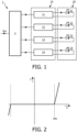
- Figure 1 shows a block diagram schematically illustrating a prior art design of an illumination system 1 comprising driver means 10 and an LED system 20, wherein in this example the LED system 20 comprises four LEDs 21, 22, 23, 24.
- the driver means 10 actually comprises individual drivers 11, 12, 13, 14 dedicated to driving a corresponding one of the LEDs 21, 22, 23, 24.
- the illumination system 1 comprises a control device 2 receiving a user input signal Sui and calculating individual driver control signals for the individual drivers 11, 12, 13, 14. The figure clearly shows that eight wires are needed to connect the driver means 10 to the LED system 20.
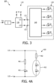
- Figure 2 is a graph schematically illustrating the electrical behavior of a diode, particularly an LED.
- the horizontal axis represents voltage (arbitrary units), the vertical axis represents current (arbitrary units).
- a diode has two terminals, one being indicated as anode and the other being indicated as cathode. Assuming that a DC voltage is applied across the diode terminals, with the anode being positive and the cathode being negative; this will be indicated as positive bias (righthand side of the graph).
- Vth the current may be considered to be zero and the diode is said to be non-conductive (it is noted that in reality a very small current may flow, but this is neglected here). If the voltage magnitude is above said threshold value Vth, the current rises very steeply as a function of voltage and the diode is said to be forwardly conductive.
- the threshold voltage Vth may be considered to be constant for a single diode specimen, although the value may be different for different types of diode. For instance, for a standard germanium diode, Vth is about 0.3 V, for a standard silicium diode, Vth is about 0.7 V, and for power LEDs, Vth may be in the range of 1 V to 3 V.
- a driver 11, 12, 13, 14 has the characteristics of a voltage source: the load determines the current, and by precisely controlling the voltage, it is possible to set the current.
- the load determines the current, and by precisely controlling the voltage, it is possible to set the current.
- slight variations in the voltage result in large variations in the LED current, while the LED output intensity may be considered to be substantially proportional to the LED current, so that visible intensity variations may result. Therefore, it is typically preferred that a driver has the characteristics of a current source. If this is the case, the load determines the output voltage of the driver. Thus, in both cases, the driver output power is determined by the load.
- FIG. 3 is a block diagram schematically illustrating the design of an illumination system 100 according to an example.
- this system has driver means 110 and an LED system 120 comprising four LEDs 21, 22, 23, 24.
- the driver means 110 comprises just one driver 130 having output terminals 131, 132, and the LED system 120 having input terminals 121, 122 comprises controllable current distribution means 140.
- the figure shows that the driver 130 is powered from the mains M, but it is noted that this, although typical, is not essential.
- a control device 2 may receive a user input signal Sui, and may control the driver 130. It is noted that this control device and driver may be integrated.
- the driver 130 has the characteristic of a current source.
- the driver 130 has the characteristic of a voltage source.
- the precise characteristic of the driver should not be interpreted as being a limiting factor. While an ideal voltage source has a vertical characteristic and an ideal current source has a horizontal characteristic, a realistic power source typically has a sloping characteristic intersecting both the current axis and the voltage axis. Nevertheless, in all cases, an LED driven by the driver may have the same working point (a point in the graph of figure 2 defined by the combination of actual voltage and actual current).
- the driver 130 has the characteristic of a voltage source, and that the control device 2 is capable of setting the driver output voltage. It is noted that LED drivers having a controllable output voltage are known per se, so that a detailed explanation thereof is not needed here. According to the principles proposed by the present invention, the output voltage of the driver 130, i.e. the input voltage received by the current distribution means 140, is considered to be a control parameter for the distribution of the current among the LEDs 21, 22, 23, 24.
- the current (function f i ) is only non-zero within a certain range of input voltages, while this range overlaps with a range of input voltages where all other LEDs have zero current, so that in this overlap range the light output has the pure color of said one LED or group of LEDs.
- the driver 130 supplies the summation of all LED currents.
- the current distribution means 140 does not comprise active processor means but consists of the hardware configuration of the LED system 120. In the following, some exemplary embodiments will be discussed.
- FIG 4A is a block diagram schematically illustrating an example of an LED system, indicated in general by the reference numeral 420.
- the input terminals are indicated by reference numerals 121, 122.
- the LED system 420 comprises two groups of LEDs 451, 452. These groups are connected in parallel to the input terminals 121, 122.
- An impedance 461 is connected in series with the first group 451 of LEDs.
- An impedance 462 is connected in series with the second group 452 of LEDs.
- this impedance is resistive, for instance a resistor.
- the first group 451 is shown by the symbol of a single LED, but this does not mean that there is only one LED in the first group.
- the group may actually comprise a plurality of LEDs arranged in series and/or in parallel with each other. These LEDs may be mutually identical, but the group may also comprise LEDs of mutually different colors. Apart from the LEDs, other electrical components may be connected in series and/or in parallel to the LEDs, for instance common diodes. While each individual LED or diode has its individual threshold voltage, as explained with reference to Figure 2 , the group 451 as a whole has a group threshold voltage VT1 which typically corresponds to the summation of the threshold voltages of LEDs arranged in series. Thus, if the group 451 consists of a series arrangement of three identical LEDs each having an individual threshold voltage Vth, the group threshold voltage VT1 of the group is equal to 3Vth.
- the second group 452 has a group threshold voltage VT2, hereinafter simply indicated as second threshold voltage, larger than the group threshold voltage VT1 of the first group 451, hereinafter simply indicated as first threshold voltage.
- the impedance value of the second impedance 462 in series with the second LED group 452 may differ from the impedance value of the first impedance 461 in series with the first LED group 451.
- the impedance value of the second impedance 462 may be smaller than the impedance value of the first impedance 461, and the second impedance 462 may even be omitted, in which case the function of second impendance will be performed by the series wiring of the second LED group 452.
- the ratio between R1 and R2 determines the ratio between the proportionality of L1 and L2 versus Vi, respectively.
- R2 is smaller than R1, so that the current in the second group 452 rises faster as a function of Vi as compared to the current in the first group 451, and it will be advantageous if the number of LEDs in the second group 452 is larger than the number of LEDs in the first group 451, such that all in all the second light output L2 rises faster than the first light output L1, as illustrated.
- the color points of the LEDs do not play any role. All individual LEDs may even be mutually identical.
- the group color point of the light output of all LEDs of the second group combined differs from the group color point of the light output of all LEDs of the first group combined, hereinafter simply indicated as first color point.
- first color point When all LED groups are placed relatively closely together, a human observer will perceive the overall light output as a blend having one blend color point.
- this blend color point travels in a straight line from the first color point towards the second color point.
- increasing the input voltage causes a change from red light to warm white light, which corresponds to the dimming of an incandescent lamp.
- Figure 4C illustrates an embodiment 430, in which the second group of LEDs 452 is connected to a node of a voltage divider 430 formed by two resistors 431, 432 connected in series between the input terminals 121, 122.
- this node provides a voltage derived from the input voltage Vi.
- the second group threshold voltage VT2 is lower than the first group threshold voltage, the second group 452 can only start to conduct if the input voltage Vi is equal to or higher than (R432 + R431)/R432 times VT2.
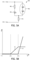
- Figure 5A illustrates an embodiment 470.
- Figure 5B is a graph comparable to Figure 4B , illustrating the behavior of this third embodiment 470.
- the second resistor 462 is replaced by a resistor 471 in series with the parallel arrangement of first group 451 and second group 452.
- the operation is the same as the operation of the example 420, with this difference that the current magnitude will be equal to (Vi - VT1)/(R1+R3), with R3 indicating the resistance of the common series resistor 471.
- the driver output voltage will result in the LED system 420; 470 as a whole generating a blend light output of which the color point travels in a straight line from the first color point towards the second color point.
- the first color point is substantially red and the second color point is substantially white.
- the first group 451 consists of precisely one red LED and the second group 452 consists of precisely two white LEDs arranged in series.
- the blend color point will not quite reach the second color point, because the first group 451 is on at all times when the second group 452 is on.
- the light colors may even be mutually equal.
- embodiments are possible where the individual LED groups are placed at a substantial distance from each other, so that for the human observer the light generated by the first group of LEDs originates from a different location than the light generated by the second group of LEDs. This can be used for generating special light effects, such as for instance running lights, a light tube, etc. Also in such embodiment, it would be desirable to be able to switch off the first group while the second group is on.
Landscapes
- Circuit Arrangement For Electric Light Sources In General (AREA)
- Control Of Indicators Other Than Cathode Ray Tubes (AREA)
- Control Of El Displays (AREA)
- Led Devices (AREA)
- Led Device Packages (AREA)
Claims (4)
- Beleuchtungssystem (100), umfassend:- einen LED-Treiber (130) zum Erzeugen einer steuerbaren Ausgangsspannung (Vi), wobei der LED-Treiber (130) zwei Ausgangsanschlüsse (131, 132) aufweist, die mit zwei Eingangsanschlüssen (121, 122) eines LED-Systems (120) gekoppelt sind, wobei der LED-Treiber (130) eine Spannungsquelle oder eine Stromquelle ist; und- das LED-System (120) umfassend:- eine erste Gruppe von LEDs (451), die eine erste Gruppenschwellenspannung (VT1) aufweisen;- eine zweite Gruppe von LEDs (452), die eine zweite Gruppenschwellenspannung (VT2) aufweisen;- passives Stromverteilungsmittel (140) in der Form einer passiven Impedanz (461), die nur in Reihe mit der ersten LED-Gruppe (451) gekoppelt ist; und- zwei Eingangsanschlüsse (121, 122), wobei die erste Gruppe von LEDs (451) in Reihe mit dem passiven Stromverteilungsmittel (140) zwischen die zwei Eingangsanschlüsse (121, 122) gekoppelt ist;wobei die erste Gruppenschwellenspannung (VT1) geringer als die zweite Gruppenschwellenspannung (VT2) ist, undwobei die passive Impedanz (461) derart ausreichend groß ist, dass ein Strom der ersten Gruppe von LEDs (451) durch die passive Impedanz (461) bestimmt wird,wobei die zweite Gruppe von LEDs (452) mit einem Knoten eines Spannungsteilers (430) gekoppelt ist, der durch zwei Widerstände (431, 432) ausgebildet ist, die in Reihe zwischen den Eingangsanschlüssen (121, 122) geschaltet sind.
- Beleuchtungssystem, umfassend:- einen LED-Treiber (130) zum Erzeugen einer steuerbaren Ausgangsspannung (Vi), wobei der LED-Treiber (130) zwei Ausgangsanschlüsse (131, 132) aufweist, die mit zwei Eingangsanschlüssen (121, 122) eines LED-Systems (120) gekoppelt sind, wobei der LED-Treiber (130) eine Spannungsquelle oder eine Stromquelle ist; und- das LED-System (120) umfassend:- eine erste Gruppe von LEDs (451), die eine erste Gruppenschwellenspannung (VT1) aufweisen;- eine zweite Gruppe von LEDs (452), die eine zweite Gruppenschwellenspannung aufweisen; und (VT2);- passives Stromverteilungsmittel (140) in der Form einer passiven Impedanz (461), die nur in Reihe mit der ersten LED-Gruppe (451) gekoppelt ist, wobei die erste Gruppe von LEDs (451) in Reihe mit dem passiven Stromverteilungsmittel (140) parallel mit der zweiten Gruppe von LEDs (452) gekoppelt ist und wobei die parallele Kombination zwischen den zwei Eingangsanschlüssen (121, 122) des LED-Systems (120) gekoppelt ist,wobei die erste Gruppenschwellenspannung (VT1) geringer als die zweite Gruppenschwellenspannung (VT2) ist, undwobei die passive Impedanz (461) derart ausreichend groß ist, dass ein Strom der ersten Gruppe von LEDs (451) durch die passive Impedanz (461) bestimmt wird,wobei die parallele Anordnung der LED-Gruppen (451; 452) in Reihe mit einem gemeinsamen Widerstand (471) geschaltet ist, wobei der gemeinsame Widerstand (471) geringer als die passive Impedanz (461) ist.
- Beleuchtungssystem nach Anspruch 2, wobei die erste Gruppe von LEDs (451) und die zweite Gruppe von LEDs (452) derart nahe beieinander montiert sind, dass ein menschlicher Beobachter den gesamten Lichtausgang als eine Mischung wahrnimmt, die einen Mischfarbpunkt aufweist.
- Beleuchtungssystem nach einem der vorstehenden Ansprüche, wobei sich die Farbpunkte der LEDs der zweiten Gruppe von LEDs (452) von den Farbpunkten der LEDs der ersten Gruppe von LEDs (451) unterscheiden.
Applications Claiming Priority (4)
| Application Number | Priority Date | Filing Date | Title |
|---|---|---|---|
| EP10192617 | 2010-11-25 | ||
| EP11799321.2A EP2644006B1 (de) | 2010-11-25 | 2011-11-15 | Beleuchtnungssytem aufweisend mehrere leds |
| EP18153789.5A EP3349544A1 (de) | 2010-11-25 | 2011-11-15 | Beleuchtungssystem mit mehreren leds |
| PCT/IB2011/055099 WO2012069961A1 (en) | 2010-11-25 | 2011-11-15 | Illumination system comprising a plurality of leds |
Related Parent Applications (2)
| Application Number | Title | Priority Date | Filing Date |
|---|---|---|---|
| EP11799321.2A Division EP2644006B1 (de) | 2010-11-25 | 2011-11-15 | Beleuchtnungssytem aufweisend mehrere leds |
| EP18153789.5A Division EP3349544A1 (de) | 2010-11-25 | 2011-11-15 | Beleuchtungssystem mit mehreren leds |
Publications (3)
| Publication Number | Publication Date |
|---|---|
| EP3512304A1 EP3512304A1 (de) | 2019-07-17 |
| EP3512304C0 EP3512304C0 (de) | 2024-09-18 |
| EP3512304B1 true EP3512304B1 (de) | 2024-09-18 |
Family
ID=45375462
Family Applications (3)
| Application Number | Title | Priority Date | Filing Date |
|---|---|---|---|
| EP19154669.6A Active EP3512304B1 (de) | 2010-11-25 | 2011-11-15 | Beleuchtungssystem mit einer vielzahl von leds |
| EP11799321.2A Active EP2644006B1 (de) | 2010-11-25 | 2011-11-15 | Beleuchtnungssytem aufweisend mehrere leds |
| EP18153789.5A Withdrawn EP3349544A1 (de) | 2010-11-25 | 2011-11-15 | Beleuchtungssystem mit mehreren leds |
Family Applications After (2)
| Application Number | Title | Priority Date | Filing Date |
|---|---|---|---|
| EP11799321.2A Active EP2644006B1 (de) | 2010-11-25 | 2011-11-15 | Beleuchtnungssytem aufweisend mehrere leds |
| EP18153789.5A Withdrawn EP3349544A1 (de) | 2010-11-25 | 2011-11-15 | Beleuchtungssystem mit mehreren leds |
Country Status (9)
| Country | Link |
|---|---|
| US (1) | US9119260B2 (de) |
| EP (3) | EP3512304B1 (de) |
| JP (1) | JP5977250B2 (de) |
| CN (1) | CN103222339B (de) |
| BR (1) | BR112013012675B1 (de) |
| ES (2) | ES2671599T3 (de) |
| RU (1) | RU2572587C2 (de) |
| TW (1) | TW201233247A (de) |
| WO (1) | WO2012069961A1 (de) |
Families Citing this family (13)
| Publication number | Priority date | Publication date | Assignee | Title |
|---|---|---|---|---|
| JP2014078374A (ja) * | 2012-10-10 | 2014-05-01 | Rohm Co Ltd | 照明機器 |
| DE102013207245B4 (de) * | 2013-04-22 | 2015-12-03 | Osram Gmbh | Ansteuerung von Halbleiterleuchtelementen sowie Lampe, Leuchte oder Leuchtsystem mit einer solchen Ansteuerung |
| JP5760044B2 (ja) * | 2013-06-14 | 2015-08-05 | フェニックス電機株式会社 | Ledランプ |
| DE102014206434A1 (de) * | 2014-04-03 | 2015-10-08 | Osram Gmbh | Ansteuerung von Halbleiterleuchtelementen |
| CN106605449B (zh) * | 2014-09-08 | 2019-06-04 | 西铁城时计株式会社 | Led驱动电路 |
| JP6536967B2 (ja) * | 2017-04-12 | 2019-07-03 | Zigenライティングソリューション株式会社 | 発光装置および照明装置 |
| DE112018003004B4 (de) | 2017-07-04 | 2021-10-28 | Rohm Co., Ltd. | Lasttreibervorrichtung, Elektrisches Gerät, Lampenmodul und Fahrzeug |
| KR102166270B1 (ko) * | 2018-08-08 | 2020-10-15 | 한국광기술원 | 분기 회로 및 그를 포함한 미세 led 패키지 |
| JP6886450B2 (ja) * | 2018-11-30 | 2021-06-16 | コイト電工株式会社 | 電源調整システム |
| JP7147656B2 (ja) * | 2019-03-27 | 2022-10-05 | 株式会社デンソーエレクトロニクス | 負荷駆動装置 |
| KR102493070B1 (ko) * | 2021-05-24 | 2023-01-31 | 엘지전자 주식회사 | 디스플레이 장치 |
| US12108503B2 (en) * | 2022-12-20 | 2024-10-01 | Electronic Theatre Controls, Inc. | Independent lighting control |
| US12538406B2 (en) | 2022-12-20 | 2026-01-27 | Electronic Theatre Controls, Inc. | Independent lighting control |
Citations (3)
| Publication number | Priority date | Publication date | Assignee | Title |
|---|---|---|---|---|
| WO2010103480A2 (en) * | 2009-03-12 | 2010-09-16 | Koninklijke Philips Electronics N.V. | Led lighting with incandescent lamp color temperature behavior |
| EP2375861A2 (de) * | 2010-04-08 | 2011-10-12 | Panasonic Electric Works Co., Ltd. | Lichtemittierende Vorrichtung |
| EP2756736A1 (de) * | 2011-09-12 | 2014-07-23 | Juno Manufacturing, LLC | Dimmbare led-beleichtung mit einstellbarer farbtemperatur |
Family Cites Families (18)
| Publication number | Priority date | Publication date | Assignee | Title |
|---|---|---|---|---|
| JP4495814B2 (ja) * | 1999-12-28 | 2010-07-07 | アビックス株式会社 | 調光式led照明器具 |
| GB0015559D0 (en) | 2000-06-27 | 2000-08-16 | Oxley Dev Co Ltd | Device controller and control arrangement |
| JP2002016290A (ja) * | 2000-06-28 | 2002-01-18 | Toshiba Lighting & Technology Corp | Led光源装置 |
| US6323598B1 (en) | 2000-09-29 | 2001-11-27 | Aerospace Optics, Inc. | Enhanced trim resolution voltage-controlled dimming led driver |
| US6653798B2 (en) * | 2000-09-29 | 2003-11-25 | Aerospace Optics, Inc. | Voltage dimmable LED display producing multiple colors |
| JP3082719U (ja) * | 2001-06-15 | 2001-12-26 | 舶用電球株式会社 | Ledランプ |
| DE10214195B4 (de) | 2002-03-28 | 2004-08-05 | Siteco Beleuchtungstechnik Gmbh | Leuchtensystem und Verfahren zum Ansteuern von mindestens zwei Leuchtmitteln |
| US7911151B2 (en) * | 2003-05-07 | 2011-03-22 | Koninklijke Philips Electronics N.V. | Single driver for multiple light emitting diodes |
| JP2006253215A (ja) * | 2005-03-08 | 2006-09-21 | Sharp Corp | 発光装置 |
| DE102005014612A1 (de) * | 2005-03-31 | 2006-10-05 | Bally Wulff Holding Gmbh & Co. Kg | Schaltungsanordnung zur Helligkeitsregelung bei mehrfarbigen Leuchtdioden |
| ES2368770T3 (es) * | 2006-05-02 | 2011-11-22 | Koninklijke Philips Electronics N.V. | Circuito de diodos emisores de luz, disposición y dispositivo. |
| RU2009102052A (ru) | 2006-06-23 | 2010-07-27 | Конинклейке Филипс Электроникс Н.В. (Nl) | Способ и устройство, предназначенные для возбуждения матрицы источников света |
| US7703943B2 (en) * | 2007-05-07 | 2010-04-27 | Intematix Corporation | Color tunable light source |
| JP2009158507A (ja) * | 2007-12-25 | 2009-07-16 | Panasonic Electric Works Co Ltd | Led発光装置およびそれを用いた照明器具 |
| TW200934294A (en) * | 2008-01-24 | 2009-08-01 | Everbright Optech Inc | Apparatus for controlling light emitting devices |
| US8004216B2 (en) * | 2008-05-02 | 2011-08-23 | The United States Of America As Represented By The Secretary Of The Navy | Variable intensity LED illumination system |
| JP2010050010A (ja) * | 2008-07-24 | 2010-03-04 | Nippon Seiki Co Ltd | 照明装置 |
| EP2366269B1 (de) | 2008-11-13 | 2012-10-10 | Koninklijke Philips Electronics N.V. | Beleuchtungssystem mit mehreren leds |
-
2011
- 2011-11-15 ES ES11799321.2T patent/ES2671599T3/es active Active
- 2011-11-15 EP EP19154669.6A patent/EP3512304B1/de active Active
- 2011-11-15 RU RU2013128872/07A patent/RU2572587C2/ru active
- 2011-11-15 JP JP2013540462A patent/JP5977250B2/ja active Active
- 2011-11-15 EP EP11799321.2A patent/EP2644006B1/de active Active
- 2011-11-15 BR BR112013012675-2A patent/BR112013012675B1/pt not_active IP Right Cessation
- 2011-11-15 US US13/988,140 patent/US9119260B2/en active Active
- 2011-11-15 EP EP18153789.5A patent/EP3349544A1/de not_active Withdrawn
- 2011-11-15 CN CN201180056689.4A patent/CN103222339B/zh active Active
- 2011-11-15 WO PCT/IB2011/055099 patent/WO2012069961A1/en not_active Ceased
- 2011-11-15 ES ES19154669T patent/ES2989334T3/es active Active
- 2011-11-24 TW TW100143220A patent/TW201233247A/zh unknown
Patent Citations (3)
| Publication number | Priority date | Publication date | Assignee | Title |
|---|---|---|---|---|
| WO2010103480A2 (en) * | 2009-03-12 | 2010-09-16 | Koninklijke Philips Electronics N.V. | Led lighting with incandescent lamp color temperature behavior |
| EP2375861A2 (de) * | 2010-04-08 | 2011-10-12 | Panasonic Electric Works Co., Ltd. | Lichtemittierende Vorrichtung |
| EP2756736A1 (de) * | 2011-09-12 | 2014-07-23 | Juno Manufacturing, LLC | Dimmbare led-beleichtung mit einstellbarer farbtemperatur |
Also Published As
| Publication number | Publication date |
|---|---|
| ES2671599T3 (es) | 2018-06-07 |
| JP5977250B2 (ja) | 2016-08-24 |
| EP3512304A1 (de) | 2019-07-17 |
| ES2989334T3 (es) | 2024-11-26 |
| BR112013012675A8 (pt) | 2017-07-11 |
| EP3512304C0 (de) | 2024-09-18 |
| CN103222339A (zh) | 2013-07-24 |
| TW201233247A (en) | 2012-08-01 |
| US20130234619A1 (en) | 2013-09-12 |
| EP2644006A1 (de) | 2013-10-02 |
| BR112013012675A2 (pt) | 2016-09-13 |
| BR112013012675B1 (pt) | 2020-12-01 |
| JP2014502411A (ja) | 2014-01-30 |
| WO2012069961A1 (en) | 2012-05-31 |
| US9119260B2 (en) | 2015-08-25 |
| CN103222339B (zh) | 2016-03-16 |
| EP2644006B1 (de) | 2018-03-28 |
| EP3349544A1 (de) | 2018-07-18 |
| RU2013128872A (ru) | 2014-12-27 |
| RU2572587C2 (ru) | 2016-01-20 |
Similar Documents
| Publication | Publication Date | Title |
|---|---|---|
| EP3512304B1 (de) | Beleuchtungssystem mit einer vielzahl von leds | |
| CA2423943C (en) | Enhanced trim resolution voltage-controlled dimming led driver | |
| US20200413514A1 (en) | Dim-to-warm led circuit | |
| US20070052376A1 (en) | Full-color led-based lighting device | |
| KR20090093949A (ko) | 스위치형 광소자 어레이 및 동작 방법 | |
| AU2001286138A1 (en) | Enhanced trim resolution voltage-controlled dimming led driver | |
| JP2012503858A (ja) | 調節可能なカラー照明光源 | |
| JP2005197304A (ja) | 発光装置 | |
| US20170311403A1 (en) | System for adaptive non-linear light dimming of electro-optical devices | |
| US20250331080A1 (en) | Control of dynamic brightness of light-emitting diode array | |
| TWI756721B (zh) | 調光調色之發光二極體電路 | |
| TWI749567B (zh) | 用於定電流驅動器之無線顏色調整 | |
| JP6481246B2 (ja) | 発光装置の制御回路および発光装置 | |
| JPH0710789U (ja) | 発光素子輝度調整装置 | |
| WO2019017014A1 (ja) | 発光装置の制御回路および発光装置 |
Legal Events
| Date | Code | Title | Description |
|---|---|---|---|
| PUAI | Public reference made under article 153(3) epc to a published international application that has entered the european phase |
Free format text: ORIGINAL CODE: 0009012 |
|
| STAA | Information on the status of an ep patent application or granted ep patent |
Free format text: STATUS: THE APPLICATION HAS BEEN PUBLISHED |
|
| AC | Divisional application: reference to earlier application |
Ref document number: 2644006 Country of ref document: EP Kind code of ref document: P Ref document number: 3349544 Country of ref document: EP Kind code of ref document: P |
|
| AK | Designated contracting states |
Kind code of ref document: A1 Designated state(s): AL AT BE BG CH CY CZ DE DK EE ES FI FR GB GR HR HU IE IS IT LI LT LU LV MC MK MT NL NO PL PT RO RS SE SI SK SM TR |
|
| STAA | Information on the status of an ep patent application or granted ep patent |
Free format text: STATUS: REQUEST FOR EXAMINATION WAS MADE |
|
| 17P | Request for examination filed |
Effective date: 20200117 |
|
| RBV | Designated contracting states (corrected) |
Designated state(s): AL AT BE BG CH CY CZ DE DK EE ES FI FR GB GR HR HU IE IS IT LI LT LU LV MC MK MT NL NO PL PT RO RS SE SI SK SM TR |
|
| STAA | Information on the status of an ep patent application or granted ep patent |
Free format text: STATUS: EXAMINATION IS IN PROGRESS |
|
| 17Q | First examination report despatched |
Effective date: 20210218 |
|
| RAP3 | Party data changed (applicant data changed or rights of an application transferred) |
Owner name: SIGNIFY HOLDING B.V. |
|
| REG | Reference to a national code |
Ref country code: DE Ref legal event code: R079 Free format text: PREVIOUS MAIN CLASS: H05B0033080000 Ipc: H05B0045200000 Ref country code: DE Ref legal event code: R079 Ref document number: 602011074993 Country of ref document: DE Free format text: PREVIOUS MAIN CLASS: H05B0033080000 Ipc: H05B0045200000 |
|
| GRAP | Despatch of communication of intention to grant a patent |
Free format text: ORIGINAL CODE: EPIDOSNIGR1 |
|
| STAA | Information on the status of an ep patent application or granted ep patent |
Free format text: STATUS: GRANT OF PATENT IS INTENDED |
|
| RIC1 | Information provided on ipc code assigned before grant |
Ipc: H05B 45/20 20200101AFI20240318BHEP |
|
| INTG | Intention to grant announced |
Effective date: 20240412 |
|
| GRAS | Grant fee paid |
Free format text: ORIGINAL CODE: EPIDOSNIGR3 |
|
| GRAA | (expected) grant |
Free format text: ORIGINAL CODE: 0009210 |
|
| STAA | Information on the status of an ep patent application or granted ep patent |
Free format text: STATUS: THE PATENT HAS BEEN GRANTED |
|
| AC | Divisional application: reference to earlier application |
Ref document number: 2644006 Country of ref document: EP Kind code of ref document: P Ref document number: 3349544 Country of ref document: EP Kind code of ref document: P |
|
| AK | Designated contracting states |
Kind code of ref document: B1 Designated state(s): AL AT BE BG CH CY CZ DE DK EE ES FI FR GB GR HR HU IE IS IT LI LT LU LV MC MK MT NL NO PL PT RO RS SE SI SK SM TR |
|
| REG | Reference to a national code |
Ref country code: GB Ref legal event code: FG4D |
|
| REG | Reference to a national code |
Ref country code: CH Ref legal event code: EP |
|
| REG | Reference to a national code |
Ref country code: IE Ref legal event code: FG4D |
|
| REG | Reference to a national code |
Ref country code: DE Ref legal event code: R096 Ref document number: 602011074993 Country of ref document: DE |
|
| U01 | Request for unitary effect filed |
Effective date: 20241011 |
|
| REG | Reference to a national code |
Ref country code: ES Ref legal event code: FG2A Ref document number: 2989334 Country of ref document: ES Kind code of ref document: T3 Effective date: 20241126 |
|
| U07 | Unitary effect registered |
Designated state(s): AT BE BG DE DK EE FI FR IT LT LU LV MT NL PT RO SE SI Effective date: 20241030 |
|
| U20 | Renewal fee for the european patent with unitary effect paid |
Year of fee payment: 14 Effective date: 20241127 |
|
| PG25 | Lapsed in a contracting state [announced via postgrant information from national office to epo] |
Ref country code: NO Free format text: LAPSE BECAUSE OF FAILURE TO SUBMIT A TRANSLATION OF THE DESCRIPTION OR TO PAY THE FEE WITHIN THE PRESCRIBED TIME-LIMIT Effective date: 20241218 |
|
| PG25 | Lapsed in a contracting state [announced via postgrant information from national office to epo] |
Ref country code: GR Free format text: LAPSE BECAUSE OF FAILURE TO SUBMIT A TRANSLATION OF THE DESCRIPTION OR TO PAY THE FEE WITHIN THE PRESCRIBED TIME-LIMIT Effective date: 20241219 |
|
| PG25 | Lapsed in a contracting state [announced via postgrant information from national office to epo] |
Ref country code: HR Free format text: LAPSE BECAUSE OF FAILURE TO SUBMIT A TRANSLATION OF THE DESCRIPTION OR TO PAY THE FEE WITHIN THE PRESCRIBED TIME-LIMIT Effective date: 20240918 |
|
| PG25 | Lapsed in a contracting state [announced via postgrant information from national office to epo] |
Ref country code: RS Free format text: LAPSE BECAUSE OF FAILURE TO SUBMIT A TRANSLATION OF THE DESCRIPTION OR TO PAY THE FEE WITHIN THE PRESCRIBED TIME-LIMIT Effective date: 20241218 |
|
| PG25 | Lapsed in a contracting state [announced via postgrant information from national office to epo] |
Ref country code: RS Free format text: LAPSE BECAUSE OF FAILURE TO SUBMIT A TRANSLATION OF THE DESCRIPTION OR TO PAY THE FEE WITHIN THE PRESCRIBED TIME-LIMIT Effective date: 20241218 Ref country code: NO Free format text: LAPSE BECAUSE OF FAILURE TO SUBMIT A TRANSLATION OF THE DESCRIPTION OR TO PAY THE FEE WITHIN THE PRESCRIBED TIME-LIMIT Effective date: 20241218 Ref country code: HR Free format text: LAPSE BECAUSE OF FAILURE TO SUBMIT A TRANSLATION OF THE DESCRIPTION OR TO PAY THE FEE WITHIN THE PRESCRIBED TIME-LIMIT Effective date: 20240918 Ref country code: GR Free format text: LAPSE BECAUSE OF FAILURE TO SUBMIT A TRANSLATION OF THE DESCRIPTION OR TO PAY THE FEE WITHIN THE PRESCRIBED TIME-LIMIT Effective date: 20241219 |
|
| PG25 | Lapsed in a contracting state [announced via postgrant information from national office to epo] |
Ref country code: IS Free format text: LAPSE BECAUSE OF FAILURE TO SUBMIT A TRANSLATION OF THE DESCRIPTION OR TO PAY THE FEE WITHIN THE PRESCRIBED TIME-LIMIT Effective date: 20250118 |
|
| PG25 | Lapsed in a contracting state [announced via postgrant information from national office to epo] |
Ref country code: SM Free format text: LAPSE BECAUSE OF FAILURE TO SUBMIT A TRANSLATION OF THE DESCRIPTION OR TO PAY THE FEE WITHIN THE PRESCRIBED TIME-LIMIT Effective date: 20240918 |
|
| PG25 | Lapsed in a contracting state [announced via postgrant information from national office to epo] |
Ref country code: CZ Free format text: LAPSE BECAUSE OF FAILURE TO SUBMIT A TRANSLATION OF THE DESCRIPTION OR TO PAY THE FEE WITHIN THE PRESCRIBED TIME-LIMIT Effective date: 20240918 Ref country code: PL Free format text: LAPSE BECAUSE OF FAILURE TO SUBMIT A TRANSLATION OF THE DESCRIPTION OR TO PAY THE FEE WITHIN THE PRESCRIBED TIME-LIMIT Effective date: 20240918 |
|
| PG25 | Lapsed in a contracting state [announced via postgrant information from national office to epo] |
Ref country code: SK Free format text: LAPSE BECAUSE OF FAILURE TO SUBMIT A TRANSLATION OF THE DESCRIPTION OR TO PAY THE FEE WITHIN THE PRESCRIBED TIME-LIMIT Effective date: 20240918 |
|
| REG | Reference to a national code |
Ref country code: CH Ref legal event code: PL |
|
| PG25 | Lapsed in a contracting state [announced via postgrant information from national office to epo] |
Ref country code: MC Free format text: LAPSE BECAUSE OF FAILURE TO SUBMIT A TRANSLATION OF THE DESCRIPTION OR TO PAY THE FEE WITHIN THE PRESCRIBED TIME-LIMIT Effective date: 20240918 |
|
| REG | Reference to a national code |
Ref country code: CH Ref legal event code: PL |
|
| PG25 | Lapsed in a contracting state [announced via postgrant information from national office to epo] |
Ref country code: CH Free format text: LAPSE BECAUSE OF NON-PAYMENT OF DUE FEES Effective date: 20241130 |
|
| PLBE | No opposition filed within time limit |
Free format text: ORIGINAL CODE: 0009261 |
|
| STAA | Information on the status of an ep patent application or granted ep patent |
Free format text: STATUS: NO OPPOSITION FILED WITHIN TIME LIMIT |
|
| 26N | No opposition filed |
Effective date: 20250619 |
|
| PG25 | Lapsed in a contracting state [announced via postgrant information from national office to epo] |
Ref country code: IE Free format text: LAPSE BECAUSE OF NON-PAYMENT OF DUE FEES Effective date: 20241115 |
|
| U20 | Renewal fee for the european patent with unitary effect paid |
Year of fee payment: 15 Effective date: 20251126 |
|
| PGFP | Annual fee paid to national office [announced via postgrant information from national office to epo] |
Ref country code: GB Payment date: 20251125 Year of fee payment: 15 |
|
| PGFP | Annual fee paid to national office [announced via postgrant information from national office to epo] |
Ref country code: ES Payment date: 20251209 Year of fee payment: 15 |
|
| PG25 | Lapsed in a contracting state [announced via postgrant information from national office to epo] |
Ref country code: HU Free format text: LAPSE BECAUSE OF FAILURE TO SUBMIT A TRANSLATION OF THE DESCRIPTION OR TO PAY THE FEE WITHIN THE PRESCRIBED TIME-LIMIT; INVALID AB INITIO Effective date: 20111115 |