EP3512053A1 - Ladestecker für elektroautos und dessen herstellung - Google Patents
Ladestecker für elektroautos und dessen herstellung Download PDFInfo
- Publication number
- EP3512053A1 EP3512053A1 EP18020510.6A EP18020510A EP3512053A1 EP 3512053 A1 EP3512053 A1 EP 3512053A1 EP 18020510 A EP18020510 A EP 18020510A EP 3512053 A1 EP3512053 A1 EP 3512053A1
- Authority
- EP
- European Patent Office
- Prior art keywords
- plug
- contact pins
- insulating body
- pins
- contact
- Prior art date
- Legal status (The legal status is an assumption and is not a legal conclusion. Google has not performed a legal analysis and makes no representation as to the accuracy of the status listed.)
- Granted
Links
- 238000004519 manufacturing process Methods 0.000 title claims description 4
- 230000001681 protective effect Effects 0.000 claims description 18
- 238000007789 sealing Methods 0.000 claims description 4
- 230000008859 change Effects 0.000 description 9
- 238000000034 method Methods 0.000 description 8
- 230000008569 process Effects 0.000 description 6
- 230000013011 mating Effects 0.000 description 5
- 239000004033 plastic Substances 0.000 description 5
- 229920003023 plastic Polymers 0.000 description 5
- 238000009413 insulation Methods 0.000 description 4
- 238000000926 separation method Methods 0.000 description 4
- 238000002788 crimping Methods 0.000 description 3
- 238000003860 storage Methods 0.000 description 3
- 238000005299 abrasion Methods 0.000 description 2
- 238000000354 decomposition reaction Methods 0.000 description 2
- 238000001514 detection method Methods 0.000 description 2
- 238000007598 dipping method Methods 0.000 description 2
- 229920001971 elastomer Polymers 0.000 description 2
- 238000003780 insertion Methods 0.000 description 2
- 230000037431 insertion Effects 0.000 description 2
- 230000009467 reduction Effects 0.000 description 2
- QVGXLLKOCUKJST-UHFFFAOYSA-N atomic oxygen Chemical compound [O] QVGXLLKOCUKJST-UHFFFAOYSA-N 0.000 description 1
- 230000004323 axial length Effects 0.000 description 1
- 230000008901 benefit Effects 0.000 description 1
- 239000004020 conductor Substances 0.000 description 1
- 238000007796 conventional method Methods 0.000 description 1
- 239000013256 coordination polymer Substances 0.000 description 1
- 230000008878 coupling Effects 0.000 description 1
- 238000010168 coupling process Methods 0.000 description 1
- 238000005859 coupling reaction Methods 0.000 description 1
- 230000001419 dependent effect Effects 0.000 description 1
- 239000000806 elastomer Substances 0.000 description 1
- 238000004870 electrical engineering Methods 0.000 description 1
- 238000004146 energy storage Methods 0.000 description 1
- MSNOMDLPLDYDME-UHFFFAOYSA-N gold nickel Chemical compound [Ni].[Au] MSNOMDLPLDYDME-UHFFFAOYSA-N 0.000 description 1
- 238000009434 installation Methods 0.000 description 1
- 239000012212 insulator Substances 0.000 description 1
- 239000012464 large buffer Substances 0.000 description 1
- 239000007788 liquid Substances 0.000 description 1
- 238000012423 maintenance Methods 0.000 description 1
- 239000000463 material Substances 0.000 description 1
- 230000005226 mechanical processes and functions Effects 0.000 description 1
- 239000007800 oxidant agent Substances 0.000 description 1
- 229910052760 oxygen Inorganic materials 0.000 description 1
- 239000001301 oxygen Substances 0.000 description 1
- 229920001296 polysiloxane Polymers 0.000 description 1
- 238000007493 shaping process Methods 0.000 description 1
- 239000000725 suspension Substances 0.000 description 1
- 238000012360 testing method Methods 0.000 description 1
- 239000002918 waste heat Substances 0.000 description 1
Images


Classifications
-
- B—PERFORMING OPERATIONS; TRANSPORTING
- B60—VEHICLES IN GENERAL
- B60L—PROPULSION OF ELECTRICALLY-PROPELLED VEHICLES; SUPPLYING ELECTRIC POWER FOR AUXILIARY EQUIPMENT OF ELECTRICALLY-PROPELLED VEHICLES; ELECTRODYNAMIC BRAKE SYSTEMS FOR VEHICLES IN GENERAL; MAGNETIC SUSPENSION OR LEVITATION FOR VEHICLES; MONITORING OPERATING VARIABLES OF ELECTRICALLY-PROPELLED VEHICLES; ELECTRIC SAFETY DEVICES FOR ELECTRICALLY-PROPELLED VEHICLES
- B60L53/00—Methods of charging batteries, specially adapted for electric vehicles; Charging stations or on-board charging equipment therefor; Exchange of energy storage elements in electric vehicles
- B60L53/10—Methods of charging batteries, specially adapted for electric vehicles; Charging stations or on-board charging equipment therefor; Exchange of energy storage elements in electric vehicles characterised by the energy transfer between the charging station and the vehicle
- B60L53/14—Conductive energy transfer
- B60L53/16—Connectors, e.g. plugs or sockets, specially adapted for charging electric vehicles
-
- H—ELECTRICITY
- H01—ELECTRIC ELEMENTS
- H01R—ELECTRICALLY-CONDUCTIVE CONNECTIONS; STRUCTURAL ASSOCIATIONS OF A PLURALITY OF MUTUALLY-INSULATED ELECTRICAL CONNECTING ELEMENTS; COUPLING DEVICES; CURRENT COLLECTORS
- H01R13/00—Details of coupling devices of the kinds covered by groups H01R12/70 or H01R24/00 - H01R33/00
- H01R13/64—Means for preventing incorrect coupling
- H01R13/645—Means for preventing incorrect coupling by exchangeable elements on case or base
-
- B—PERFORMING OPERATIONS; TRANSPORTING
- B60—VEHICLES IN GENERAL
- B60L—PROPULSION OF ELECTRICALLY-PROPELLED VEHICLES; SUPPLYING ELECTRIC POWER FOR AUXILIARY EQUIPMENT OF ELECTRICALLY-PROPELLED VEHICLES; ELECTRODYNAMIC BRAKE SYSTEMS FOR VEHICLES IN GENERAL; MAGNETIC SUSPENSION OR LEVITATION FOR VEHICLES; MONITORING OPERATING VARIABLES OF ELECTRICALLY-PROPELLED VEHICLES; ELECTRIC SAFETY DEVICES FOR ELECTRICALLY-PROPELLED VEHICLES
- B60L53/00—Methods of charging batteries, specially adapted for electric vehicles; Charging stations or on-board charging equipment therefor; Exchange of energy storage elements in electric vehicles
- B60L53/10—Methods of charging batteries, specially adapted for electric vehicles; Charging stations or on-board charging equipment therefor; Exchange of energy storage elements in electric vehicles characterised by the energy transfer between the charging station and the vehicle
- B60L53/14—Conductive energy transfer
- B60L53/18—Cables specially adapted for charging electric vehicles
-
- H—ELECTRICITY
- H01—ELECTRIC ELEMENTS
- H01R—ELECTRICALLY-CONDUCTIVE CONNECTIONS; STRUCTURAL ASSOCIATIONS OF A PLURALITY OF MUTUALLY-INSULATED ELECTRICAL CONNECTING ELEMENTS; COUPLING DEVICES; CURRENT COLLECTORS
- H01R13/00—Details of coupling devices of the kinds covered by groups H01R12/70 or H01R24/00 - H01R33/00
- H01R13/02—Contact members
- H01R13/10—Sockets for co-operation with pins or blades
- H01R13/11—Resilient sockets
- H01R13/111—Resilient sockets co-operating with pins having a circular transverse section
-
- H—ELECTRICITY
- H01—ELECTRIC ELEMENTS
- H01R—ELECTRICALLY-CONDUCTIVE CONNECTIONS; STRUCTURAL ASSOCIATIONS OF A PLURALITY OF MUTUALLY-INSULATED ELECTRICAL CONNECTING ELEMENTS; COUPLING DEVICES; CURRENT COLLECTORS
- H01R13/00—Details of coupling devices of the kinds covered by groups H01R12/70 or H01R24/00 - H01R33/00
- H01R13/40—Securing contact members in or to a base or case; Insulating of contact members
- H01R13/42—Securing in a demountable manner
- H01R13/428—Securing in a demountable manner by resilient locking means on the contact members; by locking means on resilient contact members
- H01R13/434—Securing in a demountable manner by resilient locking means on the contact members; by locking means on resilient contact members by separate resilient locking means on contact member, e.g. retainer collar or ring around contact member
-
- H—ELECTRICITY
- H01—ELECTRIC ELEMENTS
- H01R—ELECTRICALLY-CONDUCTIVE CONNECTIONS; STRUCTURAL ASSOCIATIONS OF A PLURALITY OF MUTUALLY-INSULATED ELECTRICAL CONNECTING ELEMENTS; COUPLING DEVICES; CURRENT COLLECTORS
- H01R13/00—Details of coupling devices of the kinds covered by groups H01R12/70 or H01R24/00 - H01R33/00
- H01R13/44—Means for preventing access to live contacts
-
- H—ELECTRICITY
- H01—ELECTRIC ELEMENTS
- H01R—ELECTRICALLY-CONDUCTIVE CONNECTIONS; STRUCTURAL ASSOCIATIONS OF A PLURALITY OF MUTUALLY-INSULATED ELECTRICAL CONNECTING ELEMENTS; COUPLING DEVICES; CURRENT COLLECTORS
- H01R13/00—Details of coupling devices of the kinds covered by groups H01R12/70 or H01R24/00 - H01R33/00
- H01R13/46—Bases; Cases
- H01R13/502—Bases; Cases composed of different pieces
- H01R13/506—Bases; Cases composed of different pieces assembled by snap action of the parts
-
- H—ELECTRICITY
- H01—ELECTRIC ELEMENTS
- H01R—ELECTRICALLY-CONDUCTIVE CONNECTIONS; STRUCTURAL ASSOCIATIONS OF A PLURALITY OF MUTUALLY-INSULATED ELECTRICAL CONNECTING ELEMENTS; COUPLING DEVICES; CURRENT COLLECTORS
- H01R13/00—Details of coupling devices of the kinds covered by groups H01R12/70 or H01R24/00 - H01R33/00
- H01R13/46—Bases; Cases
- H01R13/52—Dustproof, splashproof, drip-proof, waterproof, or flameproof cases
- H01R13/5202—Sealing means between parts of housing or between housing part and a wall, e.g. sealing rings
-
- H—ELECTRICITY
- H01—ELECTRIC ELEMENTS
- H01R—ELECTRICALLY-CONDUCTIVE CONNECTIONS; STRUCTURAL ASSOCIATIONS OF A PLURALITY OF MUTUALLY-INSULATED ELECTRICAL CONNECTING ELEMENTS; COUPLING DEVICES; CURRENT COLLECTORS
- H01R13/00—Details of coupling devices of the kinds covered by groups H01R12/70 or H01R24/00 - H01R33/00
- H01R13/46—Bases; Cases
- H01R13/533—Bases, cases made for use in extreme conditions, e.g. high temperature, radiation, vibration, corrosive environment, pressure
-
- H—ELECTRICITY
- H01—ELECTRIC ELEMENTS
- H01R—ELECTRICALLY-CONDUCTIVE CONNECTIONS; STRUCTURAL ASSOCIATIONS OF A PLURALITY OF MUTUALLY-INSULATED ELECTRICAL CONNECTING ELEMENTS; COUPLING DEVICES; CURRENT COLLECTORS
- H01R27/00—Coupling parts adapted for co-operation with two or more dissimilar counterparts
- H01R27/02—Coupling parts adapted for co-operation with two or more dissimilar counterparts for simultaneous co-operation with two or more dissimilar counterparts
-
- H—ELECTRICITY
- H01—ELECTRIC ELEMENTS
- H01R—ELECTRICALLY-CONDUCTIVE CONNECTIONS; STRUCTURAL ASSOCIATIONS OF A PLURALITY OF MUTUALLY-INSULATED ELECTRICAL CONNECTING ELEMENTS; COUPLING DEVICES; CURRENT COLLECTORS
- H01R31/00—Coupling parts supported only by co-operation with counterpart
- H01R31/06—Intermediate parts for linking two coupling parts, e.g. adapter
-
- H—ELECTRICITY
- H01—ELECTRIC ELEMENTS
- H01R—ELECTRICALLY-CONDUCTIVE CONNECTIONS; STRUCTURAL ASSOCIATIONS OF A PLURALITY OF MUTUALLY-INSULATED ELECTRICAL CONNECTING ELEMENTS; COUPLING DEVICES; CURRENT COLLECTORS
- H01R43/00—Apparatus or processes specially adapted for manufacturing, assembling, maintaining, or repairing of line connectors or current collectors or for joining electric conductors
- H01R43/20—Apparatus or processes specially adapted for manufacturing, assembling, maintaining, or repairing of line connectors or current collectors or for joining electric conductors for assembling or disassembling contact members with insulating base, case or sleeve
-
- H—ELECTRICITY
- H01—ELECTRIC ELEMENTS
- H01R—ELECTRICALLY-CONDUCTIVE CONNECTIONS; STRUCTURAL ASSOCIATIONS OF A PLURALITY OF MUTUALLY-INSULATED ELECTRICAL CONNECTING ELEMENTS; COUPLING DEVICES; CURRENT COLLECTORS
- H01R11/00—Individual connecting elements providing two or more spaced connecting locations for conductive members which are, or may be, thereby interconnected, e.g. end pieces for wires or cables supported by the wire or cable and having means for facilitating electrical connection to some other wire, terminal, or conductive member, blocks of binding posts
- H01R11/11—End pieces or tapping pieces for wires, supported by the wire and for facilitating electrical connection to some other wire, terminal or conductive member
- H01R11/28—End pieces consisting of a ferrule or sleeve
- H01R11/281—End pieces consisting of a ferrule or sleeve for connections to batteries
-
- H—ELECTRICITY
- H01—ELECTRIC ELEMENTS
- H01R—ELECTRICALLY-CONDUCTIVE CONNECTIONS; STRUCTURAL ASSOCIATIONS OF A PLURALITY OF MUTUALLY-INSULATED ELECTRICAL CONNECTING ELEMENTS; COUPLING DEVICES; CURRENT COLLECTORS
- H01R2201/00—Connectors or connections adapted for particular applications
- H01R2201/26—Connectors or connections adapted for particular applications for vehicles
-
- Y—GENERAL TAGGING OF NEW TECHNOLOGICAL DEVELOPMENTS; GENERAL TAGGING OF CROSS-SECTIONAL TECHNOLOGIES SPANNING OVER SEVERAL SECTIONS OF THE IPC; TECHNICAL SUBJECTS COVERED BY FORMER USPC CROSS-REFERENCE ART COLLECTIONS [XRACs] AND DIGESTS
- Y02—TECHNOLOGIES OR APPLICATIONS FOR MITIGATION OR ADAPTATION AGAINST CLIMATE CHANGE
- Y02T—CLIMATE CHANGE MITIGATION TECHNOLOGIES RELATED TO TRANSPORTATION
- Y02T10/00—Road transport of goods or passengers
- Y02T10/60—Other road transportation technologies with climate change mitigation effect
- Y02T10/70—Energy storage systems for electromobility, e.g. batteries
-
- Y—GENERAL TAGGING OF NEW TECHNOLOGICAL DEVELOPMENTS; GENERAL TAGGING OF CROSS-SECTIONAL TECHNOLOGIES SPANNING OVER SEVERAL SECTIONS OF THE IPC; TECHNICAL SUBJECTS COVERED BY FORMER USPC CROSS-REFERENCE ART COLLECTIONS [XRACs] AND DIGESTS
- Y02—TECHNOLOGIES OR APPLICATIONS FOR MITIGATION OR ADAPTATION AGAINST CLIMATE CHANGE
- Y02T—CLIMATE CHANGE MITIGATION TECHNOLOGIES RELATED TO TRANSPORTATION
- Y02T10/00—Road transport of goods or passengers
- Y02T10/60—Other road transportation technologies with climate change mitigation effect
- Y02T10/7072—Electromobility specific charging systems or methods for batteries, ultracapacitors, supercapacitors or double-layer capacitors
-
- Y—GENERAL TAGGING OF NEW TECHNOLOGICAL DEVELOPMENTS; GENERAL TAGGING OF CROSS-SECTIONAL TECHNOLOGIES SPANNING OVER SEVERAL SECTIONS OF THE IPC; TECHNICAL SUBJECTS COVERED BY FORMER USPC CROSS-REFERENCE ART COLLECTIONS [XRACs] AND DIGESTS
- Y02—TECHNOLOGIES OR APPLICATIONS FOR MITIGATION OR ADAPTATION AGAINST CLIMATE CHANGE
- Y02T—CLIMATE CHANGE MITIGATION TECHNOLOGIES RELATED TO TRANSPORTATION
- Y02T90/00—Enabling technologies or technologies with a potential or indirect contribution to GHG emissions mitigation
- Y02T90/10—Technologies relating to charging of electric vehicles
- Y02T90/14—Plug-in electric vehicles
Definitions
- the present invention relates to a charging connector for electric cars.
- the present invention also relates to its production.
- any stationary device or electrical system which serves mobile battery-powered devices, machines or vehicles by simply setting or plugging energy without having to remove the energy storage - such as the traction battery of an electric car.
- Charging stations for electric cars are sometimes referred to as “charging stations” and may include multiple charging points.
- DC fast charging systems high performance charging, HPC
- HPC high performance charging
- CCS combined charging system
- DC fast charging station direct current from the charging station is fed directly into the vehicle and provided by a high-performance rectifier from the power grid or by large buffer accumulators to solar charging stations.
- a battery management system that communicates with the charging station to adjust the current level or stop it when a capacity limit is reached.
- the power electronics are usually located in the charging station. Since the direct current terminals of the charging station are connected directly to corresponding terminals of the traction battery, high charging currents can be transmitted with low loss, which allows short charging times, but also generates considerable waste heat.
- EP2555340B1 such as US2015035483 reveal electric vehicle charging plug with interchangeable sections.
- the invention provides a charging connector for electric cars and a method for its manufacture according to the independent claims.
- a basic idea of the invention is the division of the charging plug into at least one part with high wear and / or high safety function or significance and at least one part with less wear and / or lower safety function or significance.
- the part of the charging plug with high wear and / or high safety function or meaning is designed to be interchangeable.
- the vast majority of the plug which is inserted into the mechanical receptacle in the vehicle and thus exposed to mechanical abrasion and stress, interchangeable. It is advantageous that as many as possible sensitive parts (possibly also easily breaking parts of the housing) are part of the exchange part, but on the other hand as little as possible exchanged to limit the cost of the part.
- the plug or insulation body may in particular contain pins, which are also exchanged with the insulation body. If the insulating body is placed over the plug like a mask, then - in view of the frequent plugging operations with vehicles that are particularly susceptible to wear - pins can be connected to the plug via high-quality contact pins with only a few mating cycles. These additional pins require only very few mating cycles, since they are plugged only when changing the insulation body.
- the insulating body and at least one pin can be designed plugged onto the connector body.
- the insulating body should preferably be fixed to the plug, for example by means of screws, clamping springs or rivets.
- the fixation for third parties is not detachable, for example by the use of unusual screw heads, rivets, a chemically releasable bonding of the screws or a lock.
- the safety of the charging plug is increased by the fact that signal pins - for example for Steuerpilot- ( control pilot, CP) or proximity pilot signal ( proximity pilot, PP) - on the one hand and whopins other hand, at least partially separated from each other. Additional pins such as protective earth ( PE) can be assigned to any group. Furthermore, only a few pins can be assigned to the separate groups. Ideally, at least one signal pin whose signal is required for the detection and release of the plug in the charging mode and fulfills a safety-relevant function is separated from the actual power contacts.
- signal pins - for example for Steuerpilot- ( control pilot, CP) or proximity pilot signal ( proximity pilot, PP) - on the one hand and counselpins other hand, at least partially separated from each other. Additional pins such as protective earth ( PE) can be assigned to any group. Furthermore, only a few pins can be assigned to the separate groups. Ideally, at least one signal pin whose signal is required for the detection and release of the plug in the charging mode and fulfills a safety-
- the separation is carried out, for example, so that the power contacts as Kirpins on intended contacts in the actual plug head, the signal pins, however, in the connector face, which fixes the power pins are plugged, crimped or screwed and changed with this. It is also conceivable that although the power contacts as described between plug head and plug face, the signal contacts are set from the front side of the plug face in selbiges.
- This embodiment takes into account the fact that the wear of the power contacts is often higher due to the high current and the voltage than on the signal pins, so that signal and power pins should be replaced independently, for example, at other time intervals.
- the same plug face (with the embedded signal pins) can continue to be used, if its mechanical state allows it.
- the pins not directly plugged onto the plug head - such as the signal pins - can not be placed directly on the plug head, so as not to create the possibility that a user places all pins unstable or touchable on the plug head and the plug so unprotected.
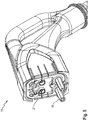
- FIG. 1 illustrates the two-part structure of a charging plug (10) according to the invention, which in this case on the one hand composed of a plug head (11) with attached DC power contact pins (18) and on the other hand an insulating body (12) with all control contacts.
- a charging plug (10) thus without insulator (12) can be completely assembled.
- the insulating body (12) is then placed over the power contact pins (18) on the plug head (11) and - for example, with the in FIG. 2 recognizable screw (13) - attached.
- control pilot contact pin (14), protective earth (15) and proximity pilot contact pin (16) via the insulating body (12) and the inside contact points (17) continuously connected to the plug head (11).
- FIGS. 6 and 7 illustrate the structure of the plug head (11) itself:
- FIG. 5 represents the plug head (11) with already mounted, preferably exchangeable exampins - the signal contact pins (14, 16) are in this embodiment in the removable insulating body (12) - are in the FIGS. 6 and 7 behind the disassembled front panel (21 - FIG. 5 ) lying pins for contacting and receiving the removable contact pins (14, 15, 16, 18) recognizable.
- FIGS. 8 . 9 and 10 illustrate the front panel (21) with the provided for the mechanical support of the Conspins in the interior of the plug head (11) contact cup (31) and attached exchangeable insulating body (12).
- FIGS. 11 to 14 One way to attach the power contact pins (18) is the FIGS. 11 to 14 refer to. Between cable (22) and power contact pin receptacle (24) there is recognizably a crimped connection (23), while the connection (25) between power contact pin receptacle (24) and associated power contact pin (18). By screwing, spring contact, crimping or plastic deformation of the power contact pin (18) 18) to produce a robust electrical contact.
- FIGS. 15 . 16 and 17 illuminate variants of the separation of plug head (11) and insulating body (12). So are in the case of FIG. 15 Signal contact pins (14, 16) and protective earth (15) arranged in the insulating body (12). Before plugging the power contact pins (18) are first placed or replaced. Thus, the necessary for the detection of the charging plug (10) signals are also scheduled in the assembly and the change process later. A only partially serviced or mounted charging plug (10) would not be recognized and unlocked in this way. Except for the "permanent" plug or plug head (11) thus all parts are provided for a change.
- the signal contact pins (14, 16) are mounted between the plug head (11) and insulating body (12) with snap rings (26) in the insulating body (12) or even pre-assembled there as a unit (arrow 27).
- the power contact pins (18) are mounted in this embodiment on the power contact pin receptacles (24) in the plug head (11), wherein the assembly is preferably carried out with disassembled front panel (21).
- the signal pin receptacles (29) are mounted in the plug head (11) so as to be behind the front panel (21) or in channels or recesses provided in the front panel (21).
- the connection between power contact pins (18) and power contact pin receptacles (24) can be a detachable connection, for example in the form of a screw connection, or a permanent connection, for example by a plastic deformation, as in crimping and crimping.
- the front panel (21) is over the Power contact pin receptacles (24) with the mounted power contact pins (18) and the signal contact pin receptacles (29) mounted such that the front plate (21) the power contact pins (18) axially against removal of the power contact pins (18) in the direction of the insulating body (12) secures and preferably by lateral walls in the front panel (21) also limited in the radial direction (see also Fig. 18 and Fig. 19 ).
- the power contact pins on a locking collar (37) have the assembled front panel (21) in the axial direction by a counterpart in the for a dipping of the power contact pins (18) provided channel is limited.
- This limitation may, for example, be shaped such that the securing collar (37) abuts against an edge formed by a reduction in diameter of the channel provided in the front panel (21) for dipping through the power contact pins (18), which further movement of the power contact pins (18). in the direction of the insulating body (12) is not possible without removal of the front panel (21).
- the pins are also replaced by a snap ring or locking ring (38 - FIG. 18 ) to form a - for maintenance purposes - as a whole interchangeable assembly.
- Fig. 16 embodiment shown further shows an insulating body (12), which can be preferably delivered as a pre-assembled component with already inserted signal contact pins (14, 16) and change contacts for the protective earth (15) for exchange to the location of the charging station.
- the signal contact pins (14, 16) and the replacement contact (s) for the protective earth (15) are preferably moved from the side abutting the front plate (21) in the recesses or channels provided for this purpose (see also FIG Fig. 18 and Fig. 19 ) used.
- the signal contact pins (14, 16) and change contacts for the protective earth (15) are axially by an abutment, for example.
- the elastic workpieces allow some radial movement under force, as they may occur, for example, in the plug-in process, so that the pins of the plug can align with those of the corresponding socket, for example in a vehicle to each other.
- the O-rings or O-rings (19) in addition to the said mechanical function additionally have a liquid-sealing function to prevent ingress of liquids and moisture through the recesses or channels of the insulating body (12) into the interior of the plug.
- snap rings (26) can be changed on the spot as a whole on the plug and on the front panel (21) to be assembled.
- a safeguard against removal of the insulating body from the front plate (21) or the plug head (11) by unauthorized persons can preferably be done by non-standard tools, for example. Screws with screw heads not compatible with standards or recessed locking springs, their backup need special tool.
- the power contact pins (18) are mounted on site on the power contact pin receptacles (24) in the plug head (11).
- the Figures 18 and 19 allow the components to be recognized in the isolated or connected state using the protective earth (15) as an example. While the inner pin (24) in the plug head (11) can be mechanically fixed - a radial clearance is dispensable in this case - are signal or PE pin (15) in the insulating body (12), for example via a fuse or O Fixed sealing ring (19). This optional sealing ring (19) around the pin (15) on the one hand ensures the mechanical seat of the axially fixed pins in the insulating body (12), but allows a targeted radial play, so that all pins fit simultaneously during assembly, but also during the mating process. It also seals the charging plug (10) according to the required IP rating.
- the old insulating body (12) and then the old power contact pins (18) are removed in this embodiment first. Then, new signal contact pins (14, 16) are placed on the signal contact pin receptacles (29) and plugged. If the signal contact pins (14, 16) are supplied separately from the insulating body (12), these are also to be mounted in the insulating body (12) and possibly to fix. The insulating body (12) with embedded signal contact pins (14, 16) is now brought and fixed via the power contact pins (18).
- the portion of the contact pins (14, 15, 16, 18), which covers the associated contact pin receptacle (24, 29) can be designed to improve the electrical contact wear susceptible for only one insertion cycle. For example, it may be softer than the contact pin receptacle (24, 29) and press plastically deforming in the contact point.
- the contact pin receptacles (24, 29) are connected to the cable (22) by conventional methods, for example crimped or soldered.
- each contact pin (14, 15, 16) can also be fixed mechanically from two sides. Radially, each contact pin (14, 15, 16) is preferably fixed by at least one flexible O-ring (19) or the like with sufficient clearance, but still largely firm grip. The O-ring (19) is replaced as a wear part together with the contact pin (14, 15, 16). Axial is a contact pin (14, 15, 16) through fixed the end face of the insulating body (12) whose opening is slightly smaller than the front surface of the contact pin (14, 15, 16) and thus this against the plug head (11) and the contact pin receptacle (29) presses.
- An elastic intermediate piece on the front side can provide for permanent pressure of the contact pin (14, 15, 16) in the contact pin receptacle (29) so that there - for example, thermally induced changes in length, purely plastic deformation, etc. - over the life of the charging plug (10 ) do not give any gaps.
- the associated trough in the insulating body (12) may be conically shaped. Thus, a certain depth of the contact pins (14, 15, 16) in the insulating body (12) is adjusted by the O-ring seal (19).
- FIG. 20 Finally, the contact separation on removal of the insulating body (12) illustrates the example of protective earth (15) and signal contact pins (14, 16). It is clear here that, as soon as the insulating body is removed, protective earth and signal contact pins (14, 15, 16) fall off, which are mechanically fixed in the insulating body (12).
- FIG. 21 shows a cross-section of the insulating body (12) according to an embodiment having an abutment (33) in at least one recess or channel for supporting the signal contact pins (14, 16), change contacts for the protective earth (15) and / or power contact pins (18). has on the front plate (21) facing away from the end face of the insulating body (12), which is formed by a taper of the diameter of the respective recess or the respective channel has.
- the abutment (33) at the same time mechanically limits the movement of the corresponding pin in the axial direction against removal, provides possible axial forces in the plugging process, during the assembly process of the insulating body on the plug head (11) or back pressure for engaging the pins in pin receptacles of the plug head (11 ) and serves as protection against contact of the electrically conductive surface of the signal contact pins (14, 16), changeover contacts for the protective earth (15) and / or power contact pins (18) through openings on the front plate (21) facing away from the end of the insulating body (12) ,
- the particular advantage of this embodiment is in the simultaneous provision of a contact protection and the mechanical storage by the same element.
- FIG. 22 illustrates the geometric relationships of the embodiment according to FIG. 21 .
- the diameter taper is formed here such that its axial length (34) is at least so large that the tip (35) of a standard or test finger, for example.
- EN 60529 or EN 50274 with its smallest segment or its measured at the local radius of curvature (36) - smallest rounding through an opening can not penetrate so far that it can touch the conductive surface of a pin (14, 15, 16, 18).
- the radial length of the reduced diameter segment is further increased by the prescribed creepage distance for the corresponding voltage of the pin.
Landscapes
- Engineering & Computer Science (AREA)
- Power Engineering (AREA)
- Transportation (AREA)
- Mechanical Engineering (AREA)
- Manufacturing & Machinery (AREA)
- Connector Housings Or Holding Contact Members (AREA)
- Details Of Connecting Devices For Male And Female Coupling (AREA)
- Charge And Discharge Circuits For Batteries Or The Like (AREA)
Abstract
Description
- Die vorliegende Erfindung betrifft einen Ladestecker für Elektroautos. Die vorliegende Erfindung betrifft darüber hinaus dessen Herstellung.
- Als Ladestation wird in der Elektrotechnik jedwede stationäre Vorrichtung oder elektrische Anlage bezeichnet, welche dazu dient, mobilen akkubetriebenen Geräten, Maschinen oder Kraftfahrzeugen durch einfaches Einstellen oder Einstecken Energie zuzuführen, ohne den Energiespeicher - etwa die Traktionsbatterie eines Elektroautos - entnehmen zu müssen. Ladestationen für Elektroautos werden mitunter auch als "Stromtankstellen" bezeichnet und können mehrere Ladepunkte umfassen.
- Bekannt sind hier insbesondere Gleichstrom-Schnellladesysteme (high performance charging, HPC) wie das in Europa verbreitete sogenannte kombinierte Ladesystem (combined charging system, CCS). Beim gattungsmäßigen Gleichstromladen wird Gleichstrom aus der Ladesäule direkt in das Fahrzeug eingespeist und hierzu durch einen leistungsstarken Gleichrichter vom Stromnetz oder durch große Pufferakkumulatoren an Solartankstellen bereitgestellt. Im Fahrzeug befindet sich ein Batteriemanagementsystem, das mit der Ladesäule kommuniziert, um die Stromstärke anzupassen oder bei Erreichung einer Kapazitätsgrenze den Vorgang zu beenden.
- Die Leistungselektronik befindet sich hierbei üblicherweise in der Ladesäule. Da die Gleichstromanschlüsse der Ladesäule direkt mit entsprechenden Anschlüssen der Traktionsbatterie verbunden werden, lassen sich verlustarm hohe Ladeströme übertragen, was kurze Ladezeiten ermöglicht, aber auch eine beträchtliche Abwärme erzeugt.
- Für diesen Zweck sind unterschiedlichste Ladekabel sowie Ladekupplungen und -stecker bekannt, die typischerweise einem hohen Verschleiß ausgesetzt sind. Insbesondere die Kontaktstifte ("Pins") sind durch die hohe Anzahl von Steckzyklen im täglichen Gebrauch einem hohen Abrieb unterworfen. Die Abnutzung der Pins gefährdet jedoch den verlässlichen Kontakt insbesondere bei der Leitung von Signalen, die mit geringer Spannung übertragen werden. Die Kunststoffschale und die Pin-Halterung sind neben der mechanischen Abnutzung durch die häufigen Steckzyklen und die Kräfte auf die Pin-Fassungen auch der Zersetzung durch Witterung, Licht, Sauerstoff und andere Oxidationsmittel ausgesetzt. Dabei ist zu beachten, dass diese Bauteile eine sicherheitskritische Isolationsfunktion erfüllen. Dabei sind sie mitunter einer beträchtlichen mechanischen Belastung ausgesetzt, insbesondere durch ein Fallenlassen des Steckers auf den Boden. Das Kabel als relativ flexibles Element erträgt dies deutlich leichter als der Stecker.
- Ein vollständiger Ersatz des Steckers in regelmäßigen Zyklen ist daher branchenüblich, allerdings sehr kosten- und zeitintensiv. Wird der Stecker mit dem Kabel ausgetauscht, müssen die Ladesäulen in der Regel geöffnet werden, um alle Signal- und Leistungsleiter neu anzuschließen und die Kabelführung, etwaige Zugentlastungen oder Aufhängungen neu einzurichten. Werden dagegen nur der Stecker und die verschlissenen Pins ausgetauscht, so müssen in der Regel die Leitungsenden gekürzt und die neuen Pins gelötet oder gecrimpt werden. Vor Ort erweisen sich diese Verfahren als aufwändig und anfällig für Qualitätsprobleme. Ferner verringern sich mit jedem Austausch von Pins ungewollt die Kabellängen. Nach dem selektiven Austausch einzelner Pins haben die Leitungen zudem unterschiedliche Leitungslängen.
- Aufgrund des hohen Aufwandes beim Austausch von Ladekabeln im Feld werden daher teils kostenintensive widerstandsfähige Materialien verwendet, beispielsweise Gold-Nickel-Pins und zersetzungsbeständige Kunststoffe für die Stecker-Gehäuse, die jedoch den Austausch nur verzögern, nicht aber verhindern können.
-
CN105896212 ,DE102011106335 ,DE102013007330 ,EP2555340B1 sowieUS2015035483 offenbaren Elektrofahrzeug-Ladestecker mit austauschbaren Abschnitten. - Die Erfindung stellt einen Ladestecker für Elektroautos sowie ein Verfahren zu dessen Herstellung gemäß den unabhängigen Ansprüchen bereit.
- Eine Grundidee der Erfindung besteht in der Teilung des Ladesteckers in mindestens einen Teil mit hohem Verschleiß und/oder hoher Sicherheitsfunktion oder -bedeutung sowie mindestens einen Teil mit geringerem Verschleiß und/oder niedrigerer Sicherheitsfunktion oder -bedeutung. Der Teil des Ladesteckers mit hohem Verschleiß und/oder hoher Sicherheitsfunktion oder -bedeutung wird entsprechend austauschbar gestaltet.
- Beispielsweise ist im Sinne der Erfindung der überwiegende Teil des Steckers, der in die mechanische Aufnahme im Fahrzeug eingeführt und damit mechanischem Abrieb und Belastung ausgesetzt wird, austauschbar. Es ist dabei vorteilhaft, dass möglichst alle sensitiven Teile (ggf. auch leicht brechende Teile des Gehäuses) Teil des Tauschteiles sind, andererseits aber so wenig wie möglich getauscht wird, um die Kosten des Teiles zu beschränken. Der Stecker- oder Isolationskörper kann insbesondere Pins enthalten, die ebenso mit dem Isolationskörper ausgetauscht werden. Wird der Isolationskörper wie eine Maske über den Stecker aufgesetzt, können - angesichts der häufigen Steckvorgänge mit wechselnden Fahrzeugen besonders verschleißanfälligen - Pins über hochwertige Kontaktstifte mit nur wenigen Steckzyklen mit dem Stecker verbunden werden. Diese zusätzlichen Pins benötigen hierbei nur sehr wenige Steckzyklen, da diese nur beim Wechsel des Isolationskörpers gesteckt werden.
- Weitere vorteilhafte Ausgestaltungen der Erfindung sind in den abhängigen Patentansprüchen angegeben. So können der Isolationskörper und mindestens ein Pin auf den Stecker-Körper aufsteckbar gestaltet werden. In diesem Fall sollte der Isolationskörper vorzugsweise am Stecker fixiert werden, beispielsweise mittels Schrauben, Klemmfedern oder Nieten. Vorzugsweise ist die Fixierung für Dritte nicht lösbar, beispielsweise durch die Verwendung von unüblichen Schraubenköpfen, Nieten, einer chemisch lösbaren Verklebung der Schrauben oder eines Schlosses.
- Vorzugsweise wird die Sicherheit des Ladesteckers dadurch erhöht, dass Signalpins - beispielsweise für Steuerpilot- (control pilot, CP) oder Näherungspilotsignal (proximity pilot, PP) - einerseits und Leistungspins andererseits zumindest teilweise voneinander getrennt sind. Weitere Pins wie die Schutzerde (protective earth, PE) können hierbei jeglicher Gruppe zugeordnet werden. Ferner können auch nur einige Pins den getrennten Gruppen zugeordnet werden. Idealerweise ist zumindest ein Signal-Pin, dessen Signal für die Erkennung und Freigabe des Steckers im Ladebetrieb benötigt wird und eine sicherheitsrelevante Funktion erfüllt, von den eigentlichen Leistungskontakten getrennt.
- Die Trennung ist beispielsweise so ausgeführt, dass die Leistungskontakte als Wechselpins auf vorgesehene Kontakte im eigentlichen Steckerkopf, die Signalpins jedoch in das Steckergesicht, das die Leistungspins fixiert, gesteckt, gecrimpt oder geschraubt und mit diesem gewechselt werden. Denkbar ist ebenso, dass zwar die Leistungskontakte wie beschrieben zwischen Steckerkopf und Steckergesicht, die Signalkontakte jedoch von der Stirnseite des Steckergesichtes in selbiges gesetzt werden. Diese Ausgestaltung trägt dem Umstand Rechnung, dass der Verschleiß der Leistungskontakte aufgrund des hohen Stroms und der Spannung oft höher ist als auf den Signalpins, sodass Signal- und Leistungspins voneinander unabhängig, beispielsweise in anderen Zeitintervallen, ausgetauscht werden sollten. So kann in dieser Ausführungsform etwa nach dem Wechsel der Leistungspins dasselbe Steckergesicht (mit den eingebetteten Signalpins) weiterverwendet werden, wenn sein mechanischer Zustand es zulässt.
- Idealer-, aber nicht zwingenderweise lassen sich die nicht direkt auf den Steckerkopf aufzusetzenden Pins - etwa die Signalpins - nicht direkt auf den Steckerkopf setzen, um nicht die Möglichkeit zu schaffen, dass ein Nutzer alle Pins instabil oder berührbar auf den Steckerkopf setzt und den Stecker so ungeschützt steckt.
- Ausführungsbeispiele der Erfindung sind in den Zeichnungen dargestellt und werden im Folgenden näher beschrieben.
-
Figur 1 zeigt das Beispiel eines erfindungsgemäßen CCS-Ladesteckers gemäß EN 62196 Typ 2 ("IEC Typ 2"). -
Figur 2 zeigt eine Draufsicht des Ladesteckers. -
Figur 3 undFigur 4 zeigen perspektivische Ansicht eines Isolierkörpers. -
Figur 5 zeigt einen Steckerkopf mit aufgesetzten, aber wechselbaren Leistungspins. -
Figur 6 zeigt den Steckerkopf mit demontierter Frontplatte und freiem Blick auf die dahinterliegenden Pins zur Kontaktierung und Aufnahme der Wechselkontakte. -
Figur 7 zeigt den Steckerkopf mit zusätzlich demontiertem Gehäuse und - mit Ausnahme der Schutzerde - entfernten Leitungen. -
Figur 8 ,9 und10 zeigen die Frontplatte mit Kontaktschale und aufgestecktem Wechselisolierkörper ("Steckergesicht"). -
Figur 11 zeigt die perspektivische Ansicht eines Leistungskontaktes. -
Figur 12 zeigt den in einer zugehörigen Aufnahme montierten Kontakt. -
Figur 13 zeigt den in einer alternativen Aufnahme montierten Kontakt. -
Figur 14 zeigt die Aufnahme in ihren Einzelheiten ohne Kontakt. -
Figur 15 ,16 und17 zeigen Trennungsvarianten des Ladesteckers. -
Figur 18 ,19 und20 verdeutlichen weitere Aspekte der Pin-Lagerung und Montage. -
Figur 21 stellt eine besondere Ausführungsform der Pin-Lagerung mit gleichzeitiger mechanischer Lagerung und Ausformung eines Berührschutzes dar. -
Figur 22 verdeutlicht die geometrischen Verhältnisse der Ausführungsform gemäßFigur 21 . -
Figur 1 illustriert den zweigeteilten Aufbau eines erfindungsgemäßen Ladesteckers (10), der sich vorliegend einerseits aus einem Steckerkopf (11) mit aufgesetzten DC-Leistungskontaktstiften (18) und andererseits einem Isolierkörper (12) mit allen Steuerkontakten zusammensetzt. Zur Montage kann der Ladestecker (10) somit ohne Isolierkörper (12) vollständig montiert werden. Der Isolierkörper (12) wird anschließend über die Leistungskontaktstifte (18) auf den Steckerkopf (11) aufgesteckt und - beispielsweise mit der inFigur 2 erkennbaren Schraubverbindung (13) - befestigt. Auf diese Weise werden, wie eine Zusammenschau derFiguren 3 und4 erkennen lässt, Steuerpilotkontaktstift (14), Schutzerde (15) und Näherungspilotkontaktstift (16) über den Isolierkörper (12) und dessen innenseitige Kontaktpunkte (17) durchgehend mit dem Steckerkopf (11) verbunden. - Die
Figuren 5 ,6 und7 verdeutlichen den Aufbau des Steckerkopfes (11) selbst: WährendFigur 5 den Steckerkopf (11) mit bereits aufgesetzten, vorzugsweise wechselbaren Leistungspins darstellt - die Signalkontaktstifte (14, 16) befinden sich in dieser Ausführungsform im wechselbaren Isolierkörper (12) -, sind in denFiguren 6 und7 die hinter der demontierten Frontplatte (21 -Figur 5 ) liegenden Pins zur Kontaktierung und Aufnahme der wechselbaren Kontaktstifte (14, 15, 16, 18) erkennbar. DieFiguren 8 ,9 und10 veranschaulichen die Frontplatte (21) mit der zur mechanischen Halterung der Aufnahmepins im Inneren des Steckerkopfes (11) vorgesehenen Kontaktschale (31) und aufgestecktem wechselbaren Isolierkörper (12). - Eine Möglichkeit zur Anbringung der Leistungskontaktstifte (18) ist den
Figuren 11 bis 14 zu entnehmen. Zwischen Kabel (22) und Leistungskontaktstiftaufnahme (24) besteht hier erkennbar eine Crimpverbindung (23), während die Verbindung (25) zwischen Leistungskontaktstiftaufnahme (24) und zugehörigem Leistungskontaktstift (18) bspw. durch Verschraubung, Federkontakt, Crimpung oder plastische Verformung des Leistungskontaktstiftes (18) hergestellt wird, um einen robusten elektrischen Kontakt herzustellen. - Die
Figuren 15 ,16 und17 beleuchten Varianten der Trennung von Steckerkopf (11) und Isolierkörper (12). So sind im Falle derFigur 15 Signalkontaktstifte (14, 16) und Schutzerde (15) im Isolierkörper (12) angeordnet. Vor dessen Aufstecken werden zuerst die Leistungskontaktstifte (18) aufgesetzt bzw. ausgetauscht. Damit sind die für die Detektion des Ladesteckers (10) notwendigen Signale auch in der Montage und dem Wechselprozess später angesetzt. Ein nur zum Teil gewarteter oder montierter Ladestecker (10) würde auf diese Weise nicht erkannt und freigeschaltet. Bis auf den "permanenten" Steckerteil oder Steckerkopf (11) sind somit alle Teile für einen Wechsel vorgesehen. - Gemäß
Figur 16 werden die Signalkontaktstifte (14, 16) stattdessen zwischen Steckerkopf (11) und Isolierkörper (12) mit Sprengringen (26) in den Isolierkörper (12) montiert oder sind dort sogar als eine Einheit vormontiert (Pfeil 27). Die Leistungskontaktstifte (18) sind in dieser Ausführungsform auf die Leistungskontaktstiftaufnahmen (24) im Steckerkopf (11) montiert, wobei die Montage vorzugsweise bei demontierter Frontplatte (21) erfolgt. Ebenso sind in dieser Ausführungsform vorzugsweise die Signalkontaktstiftaufnahmen (29) im Steckerkopf (11) derart montiert, dass sie hinter der Frontplatte (21) oder in in der Frontplatte (21) vorliegenden Kanälen oder Vertiefungen liegen. Die Verbindung zwischen Leistungskontaktstiften (18) und Leistungskontaktstiftaufnahmen (24) kann dabei eine lösbare Verbindung, beispielsweise in Form einer Schraubverbindung, oder eine dauerhafte Verbindung, beispielsweise durch eine plastische Verformung, wie sie auch in Crimp- und Quetschverbindungen vorliegt, sein. Die Frontplatte (21) wird über die Leistungskontaktstiftaufnahmen (24) mit den aufmontierten Leistungskontaktstiften (18) und die Signalkontaktstiftaufnahmen (29) derart montiert, dass die Frontplatte (21) die Leistungskontaktstifte (18) axial gegen Entnahme der Leistungskontaktstifte (18) in Richtung des Isolierkörpers (12) sichert und vorzugsweise durch seitliche Wände in der Frontplatte (21) auch in radialer Richtung begrenzt (siehe auchFig. 18 undFig. 19 ). Für die Sicherung der Leistungskontaktstifte (18) bei montierter Frontplatte (21) gegen Entnahme in Richtung des Isolierkörpers (12) können die Leistungskontaktstifte über einen Sicherungskragen (37) verfügen, der bei montierter Frontplatte (21) in axialer Richtung durch ein Gegenstück in den für ein Durchtauchen der Leistungskontaktstifte (18) vorgesehenen Kanal begrenzt wird. Diese Begrenzung kann bspw. derart ausgeformt sein, dass der Sicherungskragen (37) gegen eine durch eine Durchmesserverringerung des für ein Durchtauchen der Leistungskontaktstifte (18) vorgesehenen Kanals in der Frontplatte (21) gebildete Kante stößt, die eine weitere Bewegung der Leistungskontaktstifte (18) in Richtung des Isolierkörpers (12) nicht ohne Entfernung der Frontplatte (21) möglich ist. Die Pins werden zudem durch einen Sprengring oder Sicherungsring (38 -Figur 18 ) fixiert, um eine - etwa zu Wartungszwecken - als Ganze austauschbare Baugruppe zu bilden. - Die in
Fig. 16 dargestellte Ausführungsform zeigt ferner einen Isolierkörper (12), der vorzugsweise als vormontiertes Zusammenbauteil mit bereits eingesetzten Signalkontaktstiften (14, 16) und Wechselkontakten für die Schutzerde (15) für einen Tausch an den Ort der Ladestation geliefert werden kann. Die Signalkontaktstifte (14, 16) und der oder die Wechselkontakte für die Schutzerde (15) werden in dieser Ausführungsform bevorzugt von der im montierten Zustand an die Frontplatte (21) stoßenden Seite in für diesen Zweck vorgesehene Vertiefungen oder Kanäle (siehe auchFig. 18 undFig. 19 ) eingesetzt. Auf der dieser Einführungsseite abgewandten Seite werden die Signalkontaktstifte (14, 16) und Wechselkontakte für die Schutzerde (15) axial durch ein Widerlager, bspw. eine durch eine Durchmesserverringerung der Vertiefungen oder Kanäle gebildete Kante, an die die Frontseite der jeweiligen Signalkontaktstifte (14, 16) und Wechselkontakte für die Schutzerde (15) zwingend stoßen, begrenzt. Diese Widerlager können im Sinne der Erfindung ferner gleichzeitig als Berührschutz gegen Berühren der leitenden Oberflächen der Signalkontaktstifte (14, 16) und/oder Wechselkontakte für die Schutzerde (15) ausgeführt werden (siehe auchFig. 21 ). Auf der Einführungsseite können die Signalkontaktstifte (14, 16) und Wechselkontakte für die Schutzerde (15) nach dem Einsetzen bspw. durch eine Sicherung axial gesichert werden. Bei dieser Sicherung kann es sich wie inFig. 16 dargestellt jeweils um einen Sprengring (26) handeln. Radial können die Signalkontaktstifte (14, 16) und Wechselkontakte für die Schutzerde (15) durch die Wände der jeweiligen Vertiefung oder Kanäle im Isolierkörper (12), vorzugsweise mit leichter radialer Beweglichkeit, gelagert werden. Eine gewisse geometrische Flexibilität, die die Steckbarkeit bei nicht perfekten Pinabständen und Toleranzen vereinfacht, bei gleichzeitiger Sicherung kann durch elastische Werkstücke, beispielsweise O-Ringen oder O-Dichtringen (19) aus Elastomeren wie Kautschuk, Silikon oder dergleichen gewährleistet. Die elastischen Werkstücke erlauben gewisse radiale Bewegung bei Krafteinwirkung, wie sie beispielsweise im Steckprozess auftreten können, damit die Pins des Steckers sich mit jenen der entsprechenden Buchse, beispielsweise in einem Fahrzeug, aufeinander ausrichten können. Die O-Ringe oder O-Dichtringe (19) können neben der genannten mechanischen Funktion zusätzlich eine flüssigkeitsdichtende Funktion aufweisen, um ein Eindringen von Flüssigkeiten und Feuchte durch die Vertiefungen oder Kanäle des Isolierkörpers (12) in das Innere des Steckers zu unterbinden. Der vormontierte Isolierkörper (12) mit Signalkontaktstifte (14, 16) und/oder Wechselkontakte für die Schutzerde (15) und optionaler Sicherung, bspw. durch Sprengringe (26), kann vor Ort als Ganzes am Stecker gewechselt und auf die Frontplatte (21) montiert werden. Eine Sicherung gegen Entnahme des Isolierkörpers von der Frontplatte (21) oder dem Steckerkopf (11) durch Unbefugte kann vorzugsweise durch nicht genormte Werkzeuge, bspw. Schrauben mit nicht mit Normen kompatiblen Schraubenköpfen oder vertieften Sicherungsfedern, deren Entsicherung Spezialwerkzeug benötigen, erfolgen. - In der Ausführungsform der
Figur 17 werden zusätzlich die Leistungskontaktstifte (18) vor Ort auf die Leistungskontaktstiftaufnahmen (24) im Steckerkopf (11) montiert. - Die
Figuren 18 und19 lassen die Komponenten bei der Montage am Beispiel der Schutzerde (15) im getrennten bzw. verbundenen Zustand erkennen. Während der innere Pin (24) im Steckerkopf (11) mechanisch fix liegen kann - ein radiales Spiel ist in diesem Fall entbehrlich -, sind Signal- oder PE-Pin (15) im Isolierkörper (12) beispielsweise über einen Sicherungs- oder O-Dichtring (19) fixiert. Dieser optionale Dichtring (19) um den Pin (15) stellt einerseits den mechanischen Sitz des axial fixierten Pins im Isolierkörper (12) sicher, lässt aber gezielt ein radiales Spiel zu, damit beim Montage-, aber auch beim Steckvorgang alle Pins gleichzeitig passen. Er dichtet den Ladestecker (10) zudem gemäß der erforderlichen IP-Klasse ab. - Zur Montage vor Ort werden in dieser Ausführungsform zunächst der alte Isolierkörper (12) und anschließend die alten Leistungskontaktstifte (18) entfernt. Sodann werden neue Signalkontaktstifte (14, 16) auf den Signalkontaktstiftaufnahmen (29) platziert und aufgesteckt. Falls die Signalkontaktstifte (14, 16) getrennt vom Isolierkörper (12) angeliefert werden, sind diese zudem im Isolierkörper (12) zu montieren und ggf. zu fixieren. Der Isolierkörper (12) mit eingebetteten Signalkontaktstiften (14, 16) wird nun über die Leistungskontaktstifte (18) gebracht und fixiert.
- Derjenige Abschnitt der Kontaktstifte (14, 15, 16, 18), der die zugehörige Kontaktstiftaufnahme (24, 29) überdeckt, kann zur Verbesserung des elektrischen Kontaktes verschleißanfällig für nur einen Steckzyklus ausgelegt werden. Beispielsweise kann er weicher sein als die Kontaktstiftaufnahme (24, 29) und sich plastisch verformend in deren Kontaktstelle drücken. Die Kontaktstiftaufnahmen (24, 29) werden mit herkömmlichen Methoden an das Kabel (22) angeschlossen, beispielsweise gecrimpt oder gelötet.
- Die Signalkontaktstifte (14, 16) können zudem mechanisch von zwei Seiten fixiert werden. Radial wird jeder Kontaktstift (14, 15, 16) vorzugsweise von mindestens einem flexiblen O-Dichtring (19) oder dergleichen mit ausreichend Spiel, aber trotzdem weitgehend festem Halt fixiert. Der O-Dichtring (19) wird als Verschleißteil gemeinsam mit dem Kontaktstift (14, 15, 16) ausgetauscht. Axial wird ein Kontaktstift (14, 15, 16) durch die Stirnseite des Isolierkörpers (12) fixiert, deren Öffnung geringfügig kleiner ist als die vordere Fläche des Kontaktstiftes (14, 15, 16) und diesen somit gegen den Steckerkopf (11) und die Kontaktstiftaufnahme (29) drückt. Ein elastisches Zwischenstück an der Stirnseite kann für dauerhaften Druck des Kontaktstiftes (14, 15, 16) in die Kontaktstiftaufnahme (29) sorgen, damit sich dort - beispielsweise bei thermisch bedingten Längenänderungen, rein plastischen Verformungen etc. - über die Lebensdauer des Ladesteckers (10) keine Lücken ergeben. Zur Unterstützung des Montagevorganges kann die zugehörige Mulde im Isolierkörper (12) konisch geformt sein. Damit wird eine bestimmte Tiefe der Kontaktstifte (14, 15, 16) im Isolierkörper (12) durch den O-Dichtring (19) eingestellt.
-
Figur 20 schließlich verdeutlicht die Kontakttrennung bei Abnahme des Isolierkörpers (12) am Beispiel von Schutzerde (15) und Signalkontaktstiften (14, 16). Deutlich wird hier, dass, sobald der Isolationskörper entfernt wird, auch Schutzerde- und Signalkontaktstifte (14, 15, 16) abfallen, die im Isolierkörper (12) mechanisch fixiert sind. -
Figur 21 stellt einen Querschnitt des Isolierkörpers (12) gemäß einer Ausführungsform dar, der in zumindest einer Vertiefung oder einem Kanal zur Lagerung der Signalkontaktstifte (14, 16), Wechselkontakte für die Schutzerde (15) und/oder Leistungskontaktstifte (18) ein Widerlager (33) an der der Frontplatte (21) abgewandten Stirnseite des Isolierkörpers (12) aufweist, das durch eine Verjüngung des Durchmessers der jeweiligen Vertiefung oder des jeweiligen Kanals gebildet wird, aufweist. Das Widerlager (33) begrenzt gleichzeitig mechanisch die Bewegung des entsprechenden Pins in axialer Richtung gegen eine Entnahme, stellt mögliche axiale Kräfte im Steckprozess, während des Montageprozesses des Isolierkörpers auf den Steckerkopf (11) oder Gegendruck zum Einrasten der Pins in Pinaufnahmen des Steckerkopfes (11) bereit und dient als Schutz gegen ein Berühren der elektrisch leitenden Oberfläche der Signalkontaktstifte (14, 16), Wechselkontakte für die Schutzerde (15) und/oder Leistungskontaktstifte (18) durch Öffnungen auf der Frontplatte (21) abgewandten Stirnseite des Isolierkörpers (12). Der besondere Vorteil dieser Ausführungsform besteht in der gleichzeitigen Bereitstellung eines Berührschutzes und der mechanischen Lagerung durch dasselbe Element. -
Figur 22 veranschaulicht die geometrischen Verhältnisse der Ausführungsform gemäßFigur 21 . Für den Berührschutz ist die Durchmesserverjüngung hier derart ausgeformt, dass ihre axiale Länge (34) mindestens so groß ist, dass die Kuppe (35) eines Norm- oder Prüffingers, bspw. nach EN 60529 oder EN 50274, mit seinem kleinsten Segment oder seiner - gemessen am lokalen Wölbungsradius (36) - kleinsten Rundung durch eine Öffnung nicht so weit eindringen kann, dass sie die leitende Oberfläche eines Pins (14, 15, 16, 18) berühren kann. Vorzugsweise ist die radiale Länge des Segmentes mit verringertem Durchmesser ferner um die vorgeschriebene Kriechstrecke für die entsprechende Spannung des Pins erhöht.
Claims (10)
- Ladestecker (10) für ein Elektroauto,
gekennzeichnet durch folgende Merkmale:- der Ladestecker (10) umfasst einen Steckerkopf (11) und einen Isolierkörper (12) und- der Steckerkopf (11) und der Isolierkörper (12) sind derart lösbar verbunden, dass der Isolierkörper (12) ausgetauscht werden kann. - Ladestecker (10) nach Anspruch 1,
gekennzeichnet durch folgende Merkmale:- der Ladestecker (10) weist Kontaktstifte (14, 15, 16, 18) auf und- die Kontaktstifte (14, 15, 16, 18) umfassen Signalkontaktstifte (14, 16) und eine Schutzerde (15). - Ladestecker (10) nach Anspruch 2,
gekennzeichnet durch folgende Merkmale:- die Kontaktstifte (14, 15, 16, 18) weisen dem Ladestecker (10) zugewandte Kontaktpunkte (17) auf und- die Kontaktpunkte (17) definieren eine vorgesehene Trennebene (32) zwischen dem Steckerkopf (11) und dem Isolierkörper (12). - Ladestecker (10) nach Anspruch 2 oder 3,
gekennzeichnet durch folgendes Merkmal:- die Kontaktstifte (14, 15, 16, 18) sind im Isolierkörper (12) angeordnet und- die Kontaktstifte (14, 15, 16, 18) tragen Dichtringe (19). - Ladestecker (10) nach einem der Ansprüche 2 bis 4,
gekennzeichnet durch folgende Merkmale:- die Kontaktstifte (14, 15, 16, 18) umfassen Leistungskontaktstifte (18),- der Steckerkopf (11) weist ein Gehäuse (20) mit einer Frontplatte (21) auf und- die Leistungskontaktstifte (18) und die Frontplatte (21) sind derart lösbar verbunden, dass die Leistungskontaktstifte (18) ausgetauscht werden können. - Ladestecker (10) nach Anspruch 5,
gekennzeichnet durch folgende Merkmale:- der Steckerkopf (11) umfasst Kabel (22) und Kontaktstiftaufnahmen (24, 29),- die Kabel (22) und die Kontaktstiftaufnahmen (24, 29) stehen in einer nicht lösbaren Verbindung (23) und- die Kontaktstiftaufnahmen (24, 29) und die Kontaktstifte (14, 15, 16, 18) stehen in einer lösbaren Verbindung (25). - Ladestecker (10) nach Anspruch 6,
gekennzeichnet durch folgende Merkmale:- die Kontaktstiftaufnahmen (24, 29) umfassen Signalkontaktstiftaufnahmen (29) und Leistungskontaktstiftaufnahmen (24),- der Steckerkopf (11) umfasst eine Kontaktschale (31) und- die Kontaktschale (31) trägt die Leistungskontaktstiftaufnahmen (24). - Ladekabel (10) nach Anspruch 6 oder 7,
gekennzeichnet durch folgendes Merkmal:- der Ladestecker (10) weist einen Zusatzhandgriff (30) auf. - Ladestecker (10) nach einem der Ansprüche 6 bis 8,
gekennzeichnet durch folgendes Merkmal:- der Ladestecker (10) weist Schraubverbindungen (13), Klemmfedern oder Niete zwischen dem Steckerkopf (11) und dem Isolierkörper (12) auf. - Verfahren zur Herstellung eines Ladesteckers (10) nach einem der Ansprüche 6 bis 9,
gekennzeichnet durch folgende Merkmale:- die Signalkontaktstifte (14, 16) werden mit Sprengringen (26) in den Isolierkörper (12) montiert (27) und- die Leistungskontaktstifte (18) werden auf die Kontaktstiftaufnahmen (24, 29) im Steckerkopf (11) montiert (28).
Applications Claiming Priority (1)
| Application Number | Priority Date | Filing Date | Title |
|---|---|---|---|
| DE102018100831.7A DE102018100831A1 (de) | 2018-01-16 | 2018-01-16 | Ladestecker für Elektroautos und dessen Herstellung |
Publications (2)
| Publication Number | Publication Date |
|---|---|
| EP3512053A1 true EP3512053A1 (de) | 2019-07-17 |
| EP3512053B1 EP3512053B1 (de) | 2020-10-14 |
Family
ID=63965028
Family Applications (1)
| Application Number | Title | Priority Date | Filing Date |
|---|---|---|---|
| EP18020510.6A Active EP3512053B1 (de) | 2018-01-16 | 2018-10-18 | Ladestecker für elektroautos und dessen herstellung |
Country Status (5)
| Country | Link |
|---|---|
| US (1) | US10931061B2 (de) |
| EP (1) | EP3512053B1 (de) |
| CN (1) | CN110048273B (de) |
| DE (1) | DE102018100831A1 (de) |
| ES (1) | ES2840069T3 (de) |
Cited By (4)
| Publication number | Priority date | Publication date | Assignee | Title |
|---|---|---|---|---|
| CN111952776A (zh) * | 2020-08-11 | 2020-11-17 | 岑威 | 一种新能源汽车充电枪 |
| CN113161799A (zh) * | 2021-04-26 | 2021-07-23 | 深圳市陵盛科技有限公司 | 一种电动车充电座 |
| DE102020114166B3 (de) | 2020-05-27 | 2021-08-05 | Dr. Ing. H.C. F. Porsche Aktiengesellschaft | Ladestecker und Ladekabel zum Aufladen einer Batterie eines Elektrofahrzeugs |
| FR3142613A1 (fr) * | 2022-11-29 | 2024-05-31 | Renault | Prise de chargement électrique avec organe anti-électrisation |
Families Citing this family (19)
| Publication number | Priority date | Publication date | Assignee | Title |
|---|---|---|---|---|
| DE102017000722A1 (de) * | 2017-01-27 | 2018-08-02 | Thyssenkrupp Ag | Herstellung eines abgedichteten Steckers durch Verpressen von Klebstoff während des Fügens von Steckerkontakten und Steckergehäuse |
| DE102018100831A1 (de) * | 2018-01-16 | 2019-07-18 | Dr. Ing. H.C. F. Porsche Aktiengesellschaft | Ladestecker für Elektroautos und dessen Herstellung |
| US11121493B2 (en) * | 2019-01-11 | 2021-09-14 | Te Connectivity Corporation | Replaceable pin for terminal of charging inlet assembly |
| EP3771045A1 (de) * | 2019-07-25 | 2021-01-27 | ABB Schweiz AG | Ladeanordnung zum laden von elektrischen fahrzeugen |
| EP3770006B1 (de) * | 2019-07-25 | 2023-10-04 | ABB E-mobility B.V. | Elektrofahrzeugladesystem zum laden eines elektrofahrzeugs |
| CN211252236U (zh) * | 2019-11-11 | 2020-08-14 | 宁波宇月汽车配件科技有限公司 | 欧标交直流充电枪 |
| US11613159B2 (en) * | 2020-04-30 | 2023-03-28 | Thermo King Llc | Power protection system for a power module of a transport climate control system |
| US11628734B2 (en) | 2020-09-22 | 2023-04-18 | Argo AI, LLC | Enhanced vehicle connection |
| WO2022136133A1 (de) * | 2020-12-23 | 2022-06-30 | Weidmüller Interface GmbH & Co. KG | Stecker einer steckverbindungseinheit mit bedieneinheit |
| CN113370811A (zh) * | 2021-03-15 | 2021-09-10 | 江苏镭神智造科技有限公司 | 一种基于指纹识别的电动汽车交流充电枪 |
| US20220379750A1 (en) * | 2021-05-27 | 2022-12-01 | Ford Global Technologies, Llc | Adaptor plug for an electric vehicle |
| CN113500926B (zh) * | 2021-07-12 | 2024-02-13 | 浙江吉利控股集团有限公司 | 用于充电桩的充电线缆紧固装置及充电桩 |
| US20230020408A1 (en) * | 2021-07-15 | 2023-01-19 | Japan Aviation Electronics Industry, Limited | Charging connector |
| CN216214460U (zh) * | 2021-11-04 | 2022-04-05 | 长春捷翼汽车零部件有限公司 | 一种过渡连接的端子、充电插座和充电插头 |
| NO347723B1 (en) * | 2021-11-12 | 2024-03-11 | Easee As | Electrical connector for an electric socket for an electric plug of a charging cable, an electric socket comprising such electrical connector, a charging station comprising such electric socket and methods of connecting an electrical connector |
| DE102022100067B4 (de) * | 2022-01-03 | 2024-06-27 | Lisa Dräxlmaier GmbH | Verfahren zum herstellen eines ladesteckelements, ladesteckelement sowie ladekabeleinheit |
| DE102022107332A1 (de) | 2022-03-29 | 2023-10-05 | Kromberg & Schubert Automotive Gmbh & Co. Kg | Kontaktelement mit austauschbarer kontaktzone |
| DE102022130697A1 (de) | 2022-11-21 | 2024-05-23 | HARTING Automotive GmbH | Kompakter Ladesteckverbinder für ein Elektrofahrzeug |
| DE102022132133B3 (de) | 2022-12-05 | 2024-05-29 | Lisa Dräxlmaier GmbH | Wechseleinsatz für eine ladedose und ladedose |
Citations (8)
| Publication number | Priority date | Publication date | Assignee | Title |
|---|---|---|---|---|
| DE9304211U1 (de) * | 1993-03-20 | 1993-05-13 | Schulte-Elektrotechnik GmbH & Co KG, 5880 Lüdenscheid | Elektrischer Steckerstift |
| DE102011106335A1 (de) | 2011-07-01 | 2013-01-03 | Volkswagen Aktiengesellschaft | Vorrichtung und Verfahren zum elektrischen Laden eines Elektrofahrzeuges an einer Ladestation |
| DE102013007330A1 (de) | 2013-04-27 | 2014-10-30 | Volkswagen Aktiengesellschaft | Wechselstecker zum länderübergreifenden elektrischen Laden eines Fortbewegungsmittels |
| US20150035483A1 (en) | 2013-08-01 | 2015-02-05 | Lear Corporation | Electrical cable assembly for electric vehicle |
| EP2555340B1 (de) | 2011-08-03 | 2015-09-02 | Renault S.A.S. | Modulierbarer elektrischer Anschlussstecker, elektrisches Element für diesen Stecker, Set aus elektrischen Elementen und Elektrofahrzeug, das mit einem solchen Stecker ausgestattet ist |
| CN105896212A (zh) | 2016-05-31 | 2016-08-24 | 深圳巴斯巴科技发展有限公司 | 一种新型可转换插针的电动车连接器插头 |
| CN205790623U (zh) * | 2016-05-31 | 2016-12-07 | 深圳巴斯巴科技发展有限公司 | 一种便于维护的电动汽车充电连接器 |
| CN106532339A (zh) * | 2016-12-20 | 2017-03-22 | 实盈电子(东莞)有限公司 | 可更换插头的充电枪及其组装方法 |
Family Cites Families (23)
| Publication number | Priority date | Publication date | Assignee | Title |
|---|---|---|---|---|
| FR2703844B1 (fr) * | 1993-04-09 | 1995-05-24 | Sepm | Connecteur électrique et plus particulièrement connecteur de charge. |
| DE19944705C2 (de) * | 1999-09-17 | 2002-04-25 | Tyco Electronics Logistics Ag | Steckverbindungssystem |
| FR2979490B1 (fr) * | 2011-08-31 | 2013-08-23 | Peugeot Citroen Automobiles Sa | Procede et dispositif de controle de l'alimentation en courant d'un equipement par analyse d'aptitude, et systeme de connexion associe |
| DE202012003170U1 (de) * | 2012-03-28 | 2012-05-03 | Rosenberger Hochfrequenztechnik Gmbh & Co. Kg | Sicherungssystem für Hochstromanwendungen |
| US20140084678A1 (en) * | 2012-09-21 | 2014-03-27 | Renault S.A.S. | Modular electrical connection device/modular plug connector, electrical component for such a plug, set of electrical components and electric vehicle using said plug connector |
| CN103794922B (zh) * | 2012-10-31 | 2016-06-01 | Ls电线有限公司 | 电动车充电器的连接器 |
| CN202917735U (zh) * | 2012-11-20 | 2013-05-01 | 康联精密机电(深圳)有限公司 | 电动汽车充电枪 |
| JP2015082340A (ja) | 2013-10-21 | 2015-04-27 | 矢崎総業株式会社 | 充電コネクタ |
| DE102014223585A1 (de) * | 2014-11-19 | 2016-05-19 | Bayerische Motoren Werke Aktiengesellschaft | System und Verfahren zum Laden eines elektrischen Energiespeichers eines Fahrzeugs |
| CN204271690U (zh) * | 2014-12-02 | 2015-04-15 | 翔耀电子(深圳)有限公司 | 具有防水功能的充电枪 |
| CN105470740B (zh) * | 2015-12-28 | 2019-02-26 | 北京新能源汽车股份有限公司 | 插头及充电盒 |
| FR3046884B1 (fr) * | 2016-01-20 | 2018-01-26 | Aptiv Technologies Limited | Dispositif de connexion electrique et procede de montage d'un dispositif de connexion electrique |
| US10355406B2 (en) * | 2016-02-25 | 2019-07-16 | Molex, Llc | Electrical connector |
| DE102016105470A1 (de) * | 2016-03-23 | 2017-09-28 | Te Connectivity Germany Gmbh | Leistungselektrische Kontakteinrichtung; austauschbares, leistungselektrisches Kontaktmodul sowie leistungselektrischer Verbinder |
| DE102016206914A1 (de) * | 2016-04-22 | 2017-10-26 | Phoenix Contact E-Mobility Gmbh | Leistungskontakt mit auswechelbarem Kontaktbereich |
| CN205790263U (zh) | 2016-06-16 | 2016-12-07 | 江苏金坛绿能新能源科技有限公司 | 一种新能源汽车电池动力总成的电源分配系统 |
| CN106427649B (zh) * | 2016-11-18 | 2019-06-25 | 深圳市沃尔核材股份有限公司 | 枪头组件以及充电枪 |
| JP2018142417A (ja) * | 2017-02-27 | 2018-09-13 | ヒロセ電機株式会社 | 差動対を形成する複数のコンタクトを有するコネクタ、及び、これを用いたコネクタ装置 |
| DE102017108174A1 (de) | 2017-03-17 | 2018-09-20 | HARTING Automotive GmbH | Autoladesteckverbinder |
| WO2018171358A1 (zh) * | 2017-03-21 | 2018-09-27 | 昆山惠禾新能源科技有限公司 | 充电枪 |
| CN106887751B (zh) * | 2017-03-21 | 2019-03-29 | 昆山惠禾新能源科技有限公司 | 充电枪 |
| CN206864753U (zh) * | 2017-05-19 | 2018-01-09 | 深圳乔合里科技股份有限公司 | 可拆卸充电座 |
| DE102018100831A1 (de) * | 2018-01-16 | 2019-07-18 | Dr. Ing. H.C. F. Porsche Aktiengesellschaft | Ladestecker für Elektroautos und dessen Herstellung |
-
2018
- 2018-01-16 DE DE102018100831.7A patent/DE102018100831A1/de not_active Ceased
- 2018-10-18 ES ES18020510T patent/ES2840069T3/es active Active
- 2018-10-18 EP EP18020510.6A patent/EP3512053B1/de active Active
-
2019
- 2019-01-10 US US16/244,392 patent/US10931061B2/en active Active
- 2019-01-14 CN CN201910030990.6A patent/CN110048273B/zh active Active
Patent Citations (8)
| Publication number | Priority date | Publication date | Assignee | Title |
|---|---|---|---|---|
| DE9304211U1 (de) * | 1993-03-20 | 1993-05-13 | Schulte-Elektrotechnik GmbH & Co KG, 5880 Lüdenscheid | Elektrischer Steckerstift |
| DE102011106335A1 (de) | 2011-07-01 | 2013-01-03 | Volkswagen Aktiengesellschaft | Vorrichtung und Verfahren zum elektrischen Laden eines Elektrofahrzeuges an einer Ladestation |
| EP2555340B1 (de) | 2011-08-03 | 2015-09-02 | Renault S.A.S. | Modulierbarer elektrischer Anschlussstecker, elektrisches Element für diesen Stecker, Set aus elektrischen Elementen und Elektrofahrzeug, das mit einem solchen Stecker ausgestattet ist |
| DE102013007330A1 (de) | 2013-04-27 | 2014-10-30 | Volkswagen Aktiengesellschaft | Wechselstecker zum länderübergreifenden elektrischen Laden eines Fortbewegungsmittels |
| US20150035483A1 (en) | 2013-08-01 | 2015-02-05 | Lear Corporation | Electrical cable assembly for electric vehicle |
| CN105896212A (zh) | 2016-05-31 | 2016-08-24 | 深圳巴斯巴科技发展有限公司 | 一种新型可转换插针的电动车连接器插头 |
| CN205790623U (zh) * | 2016-05-31 | 2016-12-07 | 深圳巴斯巴科技发展有限公司 | 一种便于维护的电动汽车充电连接器 |
| CN106532339A (zh) * | 2016-12-20 | 2017-03-22 | 实盈电子(东莞)有限公司 | 可更换插头的充电枪及其组装方法 |
Cited By (5)
| Publication number | Priority date | Publication date | Assignee | Title |
|---|---|---|---|---|
| DE102020114166B3 (de) | 2020-05-27 | 2021-08-05 | Dr. Ing. H.C. F. Porsche Aktiengesellschaft | Ladestecker und Ladekabel zum Aufladen einer Batterie eines Elektrofahrzeugs |
| CN111952776A (zh) * | 2020-08-11 | 2020-11-17 | 岑威 | 一种新能源汽车充电枪 |
| CN113161799A (zh) * | 2021-04-26 | 2021-07-23 | 深圳市陵盛科技有限公司 | 一种电动车充电座 |
| FR3142613A1 (fr) * | 2022-11-29 | 2024-05-31 | Renault | Prise de chargement électrique avec organe anti-électrisation |
| WO2024115354A1 (fr) * | 2022-11-29 | 2024-06-06 | Ampere S.A.S. | Prise de chargement électrique avec organe anti-électrisation |
Also Published As
| Publication number | Publication date |
|---|---|
| CN110048273B (zh) | 2021-05-28 |
| EP3512053B1 (de) | 2020-10-14 |
| US20190217730A1 (en) | 2019-07-18 |
| ES2840069T3 (es) | 2021-07-06 |
| CN110048273A (zh) | 2019-07-23 |
| DE102018100831A1 (de) | 2019-07-18 |
| US10931061B2 (en) | 2021-02-23 |
Similar Documents
| Publication | Publication Date | Title |
|---|---|---|
| EP3512053B1 (de) | Ladestecker für elektroautos und dessen herstellung | |
| DE102012016641B4 (de) | Aufnahmeanordnung und Anschlusshalter | |
| EP3446369B1 (de) | Leistungskontakt mit auswechselbarem kontaktbereich | |
| EP3512046B1 (de) | Ladekabel und ladestation für elektroautos | |
| EP2612403B1 (de) | Elektrische komponente | |
| EP2311148B1 (de) | Vorrichtung zur herstellung einer verbindung | |
| DE102012100235B4 (de) | Kabelstecker mit Abdeckeinrichtung | |
| DE112012001981T5 (de) | Elektrisch leitender Anschluss | |
| DE102019125784B4 (de) | Ladebuchse für eine Energieversorgungsanordnung, entsprechende Energieversorgungsanordnung sowie Verfahren zum Betreiben einer Ladebuchse | |
| DE102008038641A1 (de) | Vorrichtung zur Herstellung einer Verbindung | |
| EP1370446B8 (de) | Mobiltelefoneinrichtung mit mehradrigen elektrischen verbindungseinrichtungen | |
| DE102019114229A1 (de) | Ladestecker insbesondere für ein Elektrofahrzeug und Verfahren zum Herstellen desselben. | |
| DE2401793A1 (de) | Buchsenkontakt | |
| EP3427343B1 (de) | Hochvoltverbinder | |
| LU93238B1 (de) | Steckverbinderteil für ein Ladesystem | |
| EP1154521B1 (de) | Steckverbinder und Verfahren zur Montage eines Steckverbinders | |
| DE102015204530A1 (de) | Austauschkontakt | |
| DE102016116127A1 (de) | Baukastensystem mit mehreren miteinander elektrisch verbindbaren Modulen | |
| EP1336229A1 (de) | Ladegerät | |
| WO2014121963A1 (de) | Selbstadaptierender kontakt für hochstromsteckverbindungen | |
| EP1523790A1 (de) | Steckverbindung mit zus tzlicher kontakteinrichtung, i nsbesondere zur daten bertragung | |
| WO2023078499A1 (de) | Einpoliger verbinder, mehrfachsteckverbinder und daraus bestehendes verbindersystem | |
| WO2023078498A1 (de) | Einpoliger verbinder, mehrfachsteckverbinder und daraus bestehendes verbindersystem | |
| DE102014200244B4 (de) | Trenneinrichtung zur galvanischen Trennung einer Spannungsquelle von einem elektrischen Verbraucher im Störfall umfassend ein Steckverbindersystem sowie Batteriesystem mit einer solchen Trenneinrichtung | |
| DE202017104439U1 (de) | Bestromungsadapter, Bestromungseinheit, Bestromungseinrichtung sowie System und Verwendung hierzu |
Legal Events
| Date | Code | Title | Description |
|---|---|---|---|
| PUAI | Public reference made under article 153(3) epc to a published international application that has entered the european phase |
Free format text: ORIGINAL CODE: 0009012 |
|
| STAA | Information on the status of an ep patent application or granted ep patent |
Free format text: STATUS: THE APPLICATION HAS BEEN PUBLISHED |
|
| AK | Designated contracting states |
Kind code of ref document: A1 Designated state(s): AL AT BE BG CH CY CZ DE DK EE ES FI FR GB GR HR HU IE IS IT LI LT LU LV MC MK MT NL NO PL PT RO RS SE SI SK SM TR |
|
| AX | Request for extension of the european patent |
Extension state: BA ME |
|
| STAA | Information on the status of an ep patent application or granted ep patent |
Free format text: STATUS: REQUEST FOR EXAMINATION WAS MADE |
|
| STAA | Information on the status of an ep patent application or granted ep patent |
Free format text: STATUS: EXAMINATION IS IN PROGRESS |
|
| 17P | Request for examination filed |
Effective date: 20200117 |
|
| RBV | Designated contracting states (corrected) |
Designated state(s): AL AT BE BG CH CY CZ DE DK EE ES FI FR GB GR HR HU IE IS IT LI LT LU LV MC MK MT NL NO PL PT RO RS SE SI SK SM TR |
|
| 17Q | First examination report despatched |
Effective date: 20200204 |
|
| GRAP | Despatch of communication of intention to grant a patent |
Free format text: ORIGINAL CODE: EPIDOSNIGR1 |
|
| STAA | Information on the status of an ep patent application or granted ep patent |
Free format text: STATUS: GRANT OF PATENT IS INTENDED |
|
| INTG | Intention to grant announced |
Effective date: 20200703 |
|
| GRAS | Grant fee paid |
Free format text: ORIGINAL CODE: EPIDOSNIGR3 |
|
| GRAA | (expected) grant |
Free format text: ORIGINAL CODE: 0009210 |
|
| STAA | Information on the status of an ep patent application or granted ep patent |
Free format text: STATUS: THE PATENT HAS BEEN GRANTED |
|
| AK | Designated contracting states |
Kind code of ref document: B1 Designated state(s): AL AT BE BG CH CY CZ DE DK EE ES FI FR GB GR HR HU IE IS IT LI LT LU LV MC MK MT NL NO PL PT RO RS SE SI SK SM TR |
|
| REG | Reference to a national code |
Ref country code: GB Ref legal event code: FG4D Free format text: NOT ENGLISH |
|
| REG | Reference to a national code |
Ref country code: AT Ref legal event code: REF Ref document number: 1324501 Country of ref document: AT Kind code of ref document: T Effective date: 20201015 Ref country code: CH Ref legal event code: EP |
|
| REG | Reference to a national code |
Ref country code: DE Ref legal event code: R096 Ref document number: 502018002695 Country of ref document: DE |
|
| REG | Reference to a national code |
Ref country code: IE Ref legal event code: FG4D Free format text: LANGUAGE OF EP DOCUMENT: GERMAN |
|
| REG | Reference to a national code |
Ref country code: NL Ref legal event code: MP Effective date: 20201014 |
|
| PG25 | Lapsed in a contracting state [announced via postgrant information from national office to epo] |
Ref country code: FI Free format text: LAPSE BECAUSE OF FAILURE TO SUBMIT A TRANSLATION OF THE DESCRIPTION OR TO PAY THE FEE WITHIN THE PRESCRIBED TIME-LIMIT Effective date: 20201014 Ref country code: PT Free format text: LAPSE BECAUSE OF FAILURE TO SUBMIT A TRANSLATION OF THE DESCRIPTION OR TO PAY THE FEE WITHIN THE PRESCRIBED TIME-LIMIT Effective date: 20210215 Ref country code: RS Free format text: LAPSE BECAUSE OF FAILURE TO SUBMIT A TRANSLATION OF THE DESCRIPTION OR TO PAY THE FEE WITHIN THE PRESCRIBED TIME-LIMIT Effective date: 20201014 Ref country code: NO Free format text: LAPSE BECAUSE OF FAILURE TO SUBMIT A TRANSLATION OF THE DESCRIPTION OR TO PAY THE FEE WITHIN THE PRESCRIBED TIME-LIMIT Effective date: 20210114 Ref country code: GR Free format text: LAPSE BECAUSE OF FAILURE TO SUBMIT A TRANSLATION OF THE DESCRIPTION OR TO PAY THE FEE WITHIN THE PRESCRIBED TIME-LIMIT Effective date: 20210115 |
|
| REG | Reference to a national code |
Ref country code: LT Ref legal event code: MG4D |
|
| PG25 | Lapsed in a contracting state [announced via postgrant information from national office to epo] |
Ref country code: SE Free format text: LAPSE BECAUSE OF FAILURE TO SUBMIT A TRANSLATION OF THE DESCRIPTION OR TO PAY THE FEE WITHIN THE PRESCRIBED TIME-LIMIT Effective date: 20201014 Ref country code: PL Free format text: LAPSE BECAUSE OF FAILURE TO SUBMIT A TRANSLATION OF THE DESCRIPTION OR TO PAY THE FEE WITHIN THE PRESCRIBED TIME-LIMIT Effective date: 20201014 Ref country code: IS Free format text: LAPSE BECAUSE OF FAILURE TO SUBMIT A TRANSLATION OF THE DESCRIPTION OR TO PAY THE FEE WITHIN THE PRESCRIBED TIME-LIMIT Effective date: 20210214 Ref country code: LV Free format text: LAPSE BECAUSE OF FAILURE TO SUBMIT A TRANSLATION OF THE DESCRIPTION OR TO PAY THE FEE WITHIN THE PRESCRIBED TIME-LIMIT Effective date: 20201014 Ref country code: BG Free format text: LAPSE BECAUSE OF FAILURE TO SUBMIT A TRANSLATION OF THE DESCRIPTION OR TO PAY THE FEE WITHIN THE PRESCRIBED TIME-LIMIT Effective date: 20210114 |
|
| PG25 | Lapsed in a contracting state [announced via postgrant information from national office to epo] |
Ref country code: LU Free format text: LAPSE BECAUSE OF NON-PAYMENT OF DUE FEES Effective date: 20201018 Ref country code: NL Free format text: LAPSE BECAUSE OF FAILURE TO SUBMIT A TRANSLATION OF THE DESCRIPTION OR TO PAY THE FEE WITHIN THE PRESCRIBED TIME-LIMIT Effective date: 20201014 Ref country code: HR Free format text: LAPSE BECAUSE OF FAILURE TO SUBMIT A TRANSLATION OF THE DESCRIPTION OR TO PAY THE FEE WITHIN THE PRESCRIBED TIME-LIMIT Effective date: 20201014 |
|
| REG | Reference to a national code |
Ref country code: ES Ref legal event code: FG2A Ref document number: 2840069 Country of ref document: ES Kind code of ref document: T3 Effective date: 20210706 |
|
| REG | Reference to a national code |
Ref country code: DE Ref legal event code: R097 Ref document number: 502018002695 Country of ref document: DE Ref country code: BE Ref legal event code: MM Effective date: 20201031 |
|
| PG25 | Lapsed in a contracting state [announced via postgrant information from national office to epo] |
Ref country code: RO Free format text: LAPSE BECAUSE OF FAILURE TO SUBMIT A TRANSLATION OF THE DESCRIPTION OR TO PAY THE FEE WITHIN THE PRESCRIBED TIME-LIMIT Effective date: 20201014 Ref country code: SK Free format text: LAPSE BECAUSE OF FAILURE TO SUBMIT A TRANSLATION OF THE DESCRIPTION OR TO PAY THE FEE WITHIN THE PRESCRIBED TIME-LIMIT Effective date: 20201014 Ref country code: EE Free format text: LAPSE BECAUSE OF FAILURE TO SUBMIT A TRANSLATION OF THE DESCRIPTION OR TO PAY THE FEE WITHIN THE PRESCRIBED TIME-LIMIT Effective date: 20201014 Ref country code: CZ Free format text: LAPSE BECAUSE OF FAILURE TO SUBMIT A TRANSLATION OF THE DESCRIPTION OR TO PAY THE FEE WITHIN THE PRESCRIBED TIME-LIMIT Effective date: 20201014 Ref country code: LT Free format text: LAPSE BECAUSE OF FAILURE TO SUBMIT A TRANSLATION OF THE DESCRIPTION OR TO PAY THE FEE WITHIN THE PRESCRIBED TIME-LIMIT Effective date: 20201014 Ref country code: MC Free format text: LAPSE BECAUSE OF FAILURE TO SUBMIT A TRANSLATION OF THE DESCRIPTION OR TO PAY THE FEE WITHIN THE PRESCRIBED TIME-LIMIT Effective date: 20201014 Ref country code: SM Free format text: LAPSE BECAUSE OF FAILURE TO SUBMIT A TRANSLATION OF THE DESCRIPTION OR TO PAY THE FEE WITHIN THE PRESCRIBED TIME-LIMIT Effective date: 20201014 |
|
| PLBE | No opposition filed within time limit |
Free format text: ORIGINAL CODE: 0009261 |
|
| STAA | Information on the status of an ep patent application or granted ep patent |
Free format text: STATUS: NO OPPOSITION FILED WITHIN TIME LIMIT |
|
| PG25 | Lapsed in a contracting state [announced via postgrant information from national office to epo] |
Ref country code: BE Free format text: LAPSE BECAUSE OF NON-PAYMENT OF DUE FEES Effective date: 20201031 Ref country code: DK Free format text: LAPSE BECAUSE OF FAILURE TO SUBMIT A TRANSLATION OF THE DESCRIPTION OR TO PAY THE FEE WITHIN THE PRESCRIBED TIME-LIMIT Effective date: 20201014 |
|
| 26N | No opposition filed |
Effective date: 20210715 |
|
| PG25 | Lapsed in a contracting state [announced via postgrant information from national office to epo] |
Ref country code: IE Free format text: LAPSE BECAUSE OF NON-PAYMENT OF DUE FEES Effective date: 20201018 Ref country code: AL Free format text: LAPSE BECAUSE OF FAILURE TO SUBMIT A TRANSLATION OF THE DESCRIPTION OR TO PAY THE FEE WITHIN THE PRESCRIBED TIME-LIMIT Effective date: 20201014 Ref country code: IT Free format text: LAPSE BECAUSE OF FAILURE TO SUBMIT A TRANSLATION OF THE DESCRIPTION OR TO PAY THE FEE WITHIN THE PRESCRIBED TIME-LIMIT Effective date: 20201014 |
|
| PG25 | Lapsed in a contracting state [announced via postgrant information from national office to epo] |
Ref country code: SI Free format text: LAPSE BECAUSE OF FAILURE TO SUBMIT A TRANSLATION OF THE DESCRIPTION OR TO PAY THE FEE WITHIN THE PRESCRIBED TIME-LIMIT Effective date: 20201014 |
|
| REG | Reference to a national code |
Ref country code: CH Ref legal event code: PL |
|
| PG25 | Lapsed in a contracting state [announced via postgrant information from national office to epo] |
Ref country code: IS Free format text: LAPSE BECAUSE OF FAILURE TO SUBMIT A TRANSLATION OF THE DESCRIPTION OR TO PAY THE FEE WITHIN THE PRESCRIBED TIME-LIMIT Effective date: 20210214 Ref country code: TR Free format text: LAPSE BECAUSE OF FAILURE TO SUBMIT A TRANSLATION OF THE DESCRIPTION OR TO PAY THE FEE WITHIN THE PRESCRIBED TIME-LIMIT Effective date: 20201014 Ref country code: MT Free format text: LAPSE BECAUSE OF FAILURE TO SUBMIT A TRANSLATION OF THE DESCRIPTION OR TO PAY THE FEE WITHIN THE PRESCRIBED TIME-LIMIT Effective date: 20201014 Ref country code: CY Free format text: LAPSE BECAUSE OF FAILURE TO SUBMIT A TRANSLATION OF THE DESCRIPTION OR TO PAY THE FEE WITHIN THE PRESCRIBED TIME-LIMIT Effective date: 20201014 |
|
| PG25 | Lapsed in a contracting state [announced via postgrant information from national office to epo] |
Ref country code: MK Free format text: LAPSE BECAUSE OF FAILURE TO SUBMIT A TRANSLATION OF THE DESCRIPTION OR TO PAY THE FEE WITHIN THE PRESCRIBED TIME-LIMIT Effective date: 20201014 |
|
| PG25 | Lapsed in a contracting state [announced via postgrant information from national office to epo] |
Ref country code: LI Free format text: LAPSE BECAUSE OF NON-PAYMENT OF DUE FEES Effective date: 20211031 Ref country code: CH Free format text: LAPSE BECAUSE OF NON-PAYMENT OF DUE FEES Effective date: 20211031 |
|
| P01 | Opt-out of the competence of the unified patent court (upc) registered |
Effective date: 20230526 |
|
| PGFP | Annual fee paid to national office [announced via postgrant information from national office to epo] |
Ref country code: GB Payment date: 20231020 Year of fee payment: 6 |
|
| PGFP | Annual fee paid to national office [announced via postgrant information from national office to epo] |
Ref country code: ES Payment date: 20231227 Year of fee payment: 6 |
|
| PGFP | Annual fee paid to national office [announced via postgrant information from national office to epo] |
Ref country code: FR Payment date: 20231026 Year of fee payment: 6 Ref country code: DE Payment date: 20230830 Year of fee payment: 6 |