EP3508680B1 - Dichtvorrichtung und damit versehenes sektionaltor - Google Patents
Dichtvorrichtung und damit versehenes sektionaltor Download PDFInfo
- Publication number
- EP3508680B1 EP3508680B1 EP18215761.0A EP18215761A EP3508680B1 EP 3508680 B1 EP3508680 B1 EP 3508680B1 EP 18215761 A EP18215761 A EP 18215761A EP 3508680 B1 EP3508680 B1 EP 3508680B1
- Authority
- EP
- European Patent Office
- Prior art keywords
- floor
- seal
- rail
- slide rail
- door
- Prior art date
- Legal status (The legal status is an assumption and is not a legal conclusion. Google has not performed a legal analysis and makes no representation as to the accuracy of the status listed.)
- Active
Links
Images


Classifications
-
- E—FIXED CONSTRUCTIONS
- E06—DOORS, WINDOWS, SHUTTERS, OR ROLLER BLINDS IN GENERAL; LADDERS
- E06B—FIXED OR MOVABLE CLOSURES FOR OPENINGS IN BUILDINGS, VEHICLES, FENCES OR LIKE ENCLOSURES IN GENERAL, e.g. DOORS, WINDOWS, BLINDS, GATES
- E06B3/00—Window sashes, door leaves, or like elements for closing wall or like openings; Layout of fixed or moving closures, e.g. windows in wall or like openings; Features of rigidly-mounted outer frames relating to the mounting of wing frames
- E06B3/32—Arrangements of wings characterised by the manner of movement; Arrangements of movable wings in openings; Features of wings or frames relating solely to the manner of movement of the wing
- E06B3/48—Wings connected at their edges, e.g. foldable wings
- E06B3/485—Sectional doors
- E06B3/487—Sectional doors sliding laterally
-
- E—FIXED CONSTRUCTIONS
- E05—LOCKS; KEYS; WINDOW OR DOOR FITTINGS; SAFES
- E05D—HINGES OR SUSPENSION DEVICES FOR DOORS, WINDOWS OR WINGS
- E05D15/00—Suspension arrangements for wings
- E05D15/06—Suspension arrangements for wings for wings sliding horizontally more or less in their own plane
- E05D15/12—Suspension arrangements for wings for wings sliding horizontally more or less in their own plane consisting of parts connected at their edges
-
- E—FIXED CONSTRUCTIONS
- E06—DOORS, WINDOWS, SHUTTERS, OR ROLLER BLINDS IN GENERAL; LADDERS
- E06B—FIXED OR MOVABLE CLOSURES FOR OPENINGS IN BUILDINGS, VEHICLES, FENCES OR LIKE ENCLOSURES IN GENERAL, e.g. DOORS, WINDOWS, BLINDS, GATES
- E06B7/00—Special arrangements or measures in connection with doors or windows
- E06B7/16—Sealing arrangements on wings or parts co-operating with the wings
- E06B7/22—Sealing arrangements on wings or parts co-operating with the wings by means of elastic edgings, e.g. elastic rubber tubes; by means of resilient edgings, e.g. felt or plush strips, resilient metal strips
- E06B7/23—Plastic, sponge rubber, or like strips or tubes
- E06B7/2305—Plastic, sponge rubber, or like strips or tubes with an integrally formed part for fixing the edging
- E06B7/2312—Plastic, sponge rubber, or like strips or tubes with an integrally formed part for fixing the edging with two or more sealing-lines or -planes between the wing and part co-operating with the wing
-
- E—FIXED CONSTRUCTIONS
- E06—DOORS, WINDOWS, SHUTTERS, OR ROLLER BLINDS IN GENERAL; LADDERS
- E06B—FIXED OR MOVABLE CLOSURES FOR OPENINGS IN BUILDINGS, VEHICLES, FENCES OR LIKE ENCLOSURES IN GENERAL, e.g. DOORS, WINDOWS, BLINDS, GATES
- E06B7/00—Special arrangements or measures in connection with doors or windows
- E06B7/16—Sealing arrangements on wings or parts co-operating with the wings
- E06B7/22—Sealing arrangements on wings or parts co-operating with the wings by means of elastic edgings, e.g. elastic rubber tubes; by means of resilient edgings, e.g. felt or plush strips, resilient metal strips
- E06B7/23—Plastic, sponge rubber, or like strips or tubes
- E06B7/2316—Plastic, sponge rubber, or like strips or tubes used as a seal between the floor and the wing
-
- E—FIXED CONSTRUCTIONS
- E05—LOCKS; KEYS; WINDOW OR DOOR FITTINGS; SAFES
- E05D—HINGES OR SUSPENSION DEVICES FOR DOORS, WINDOWS OR WINGS
- E05D15/00—Suspension arrangements for wings
- E05D15/06—Suspension arrangements for wings for wings sliding horizontally more or less in their own plane
- E05D15/0621—Details, e.g. suspension or supporting guides
- E05D15/0626—Details, e.g. suspension or supporting guides for wings suspended at the top
- E05D15/0656—Bottom guides
-
- E—FIXED CONSTRUCTIONS
- E05—LOCKS; KEYS; WINDOW OR DOOR FITTINGS; SAFES
- E05Y—INDEXING SCHEME ASSOCIATED WITH SUBCLASSES E05D AND E05F, RELATING TO CONSTRUCTION ELEMENTS, ELECTRIC CONTROL, POWER SUPPLY, POWER SIGNAL OR TRANSMISSION, USER INTERFACES, MOUNTING OR COUPLING, DETAILS, ACCESSORIES, AUXILIARY OPERATIONS NOT OTHERWISE PROVIDED FOR, APPLICATION THEREOF
- E05Y2201/00—Constructional elements; Accessories therefor
- E05Y2201/60—Suspension or transmission members; Accessories therefor
- E05Y2201/622—Suspension or transmission members elements
- E05Y2201/684—Rails; Tracks
-
- E—FIXED CONSTRUCTIONS
- E05—LOCKS; KEYS; WINDOW OR DOOR FITTINGS; SAFES
- E05Y—INDEXING SCHEME ASSOCIATED WITH SUBCLASSES E05D AND E05F, RELATING TO CONSTRUCTION ELEMENTS, ELECTRIC CONTROL, POWER SUPPLY, POWER SIGNAL OR TRANSMISSION, USER INTERFACES, MOUNTING OR COUPLING, DETAILS, ACCESSORIES, AUXILIARY OPERATIONS NOT OTHERWISE PROVIDED FOR, APPLICATION THEREOF
- E05Y2900/00—Application of doors, windows, wings or fittings thereof
- E05Y2900/10—Application of doors, windows, wings or fittings thereof for buildings or parts thereof
- E05Y2900/106—Application of doors, windows, wings or fittings thereof for buildings or parts thereof for garages
-
- E—FIXED CONSTRUCTIONS
- E06—DOORS, WINDOWS, SHUTTERS, OR ROLLER BLINDS IN GENERAL; LADDERS
- E06B—FIXED OR MOVABLE CLOSURES FOR OPENINGS IN BUILDINGS, VEHICLES, FENCES OR LIKE ENCLOSURES IN GENERAL, e.g. DOORS, WINDOWS, BLINDS, GATES
- E06B1/00—Border constructions of openings in walls, floors, or ceilings; Frames to be rigidly mounted in such openings
- E06B1/70—Sills; Thresholds
-
- E—FIXED CONSTRUCTIONS
- E06—DOORS, WINDOWS, SHUTTERS, OR ROLLER BLINDS IN GENERAL; LADDERS
- E06B—FIXED OR MOVABLE CLOSURES FOR OPENINGS IN BUILDINGS, VEHICLES, FENCES OR LIKE ENCLOSURES IN GENERAL, e.g. DOORS, WINDOWS, BLINDS, GATES
- E06B7/00—Special arrangements or measures in connection with doors or windows
- E06B7/16—Sealing arrangements on wings or parts co-operating with the wings
- E06B7/22—Sealing arrangements on wings or parts co-operating with the wings by means of elastic edgings, e.g. elastic rubber tubes; by means of resilient edgings, e.g. felt or plush strips, resilient metal strips
- E06B7/23—Plastic, sponge rubber, or like strips or tubes
- E06B7/2305—Plastic, sponge rubber, or like strips or tubes with an integrally formed part for fixing the edging
- E06B7/2307—Plastic, sponge rubber, or like strips or tubes with an integrally formed part for fixing the edging with a single sealing-line or -plane between the wing and the part co-operating with the wing
- E06B7/231—Plastic, sponge rubber, or like strips or tubes with an integrally formed part for fixing the edging with a single sealing-line or -plane between the wing and the part co-operating with the wing with a solid sealing part
Definitions
- the invention relates to a side sectional door with a sealing device for sealing a floor gap between a door leaf of the sectional door and the floor of a door opening to be closed by the door leaf, comprising a floor seal that can be attached to a door leaf.
- FIG. 7 a section through a known side sectional door 10 is shown, as is known in particular from [1].
- the side sectional door 10 has a sealing device 12 for sealing a floor gap 14 between the door leaf 16 and the floor 18.
- Rollers 24 arranged on the end profiles 20 on the panels 22 are guided in a guide channel 26 which is formed in a floor rail 28.
- a lip seal 30 which abuts the floor rail 28 .
- the invention has set itself the task of further improving the guidance and sealing of a sectional door.
- the invention creates a side sectional door according to claim 1.
- the invention provides a side sectional door with a sealing device for sealing a floor gap between a door leaf of the sectional door and the floor of a door opening to be closed by the door leaf, comprising a floor seal that can be attached to a door leaf, wherein the floor seal is designed in such a way that it extends over several panels of the door leaf when used as intended.
- the sealing device also includes a threshold structure that can be fixed in place on the floor and has a projecting slide rail for guiding the door leaf by engaging in a recessed structure that is formed on the undersides of the panels, the slide rail being of such a length that when the door leaf is in the closed state it extends over several Panels away interferes with the setback formation.
- the sealing device comprises a floor seal arranged on a door leaf, with the floor seal being designed in such a way that it extends over several panels of the door leaf when used as intended, and with the sealing device also having a threshold structure which can be fixed in place on the floor and has a projecting slide rail for guiding the door leaf through engaging a setback formation formed on the undersides of the panels, wherein the slide rail is of such a length that it engages the setback formation across a plurality of panels when the door leaf is closed.
- the floor seal extends continuously over all panels of the door leaf when used as intended.
- the bottom seal comprises a first sealing lip and a second sealing lip forming a channel of the recess formation therebetween for receiving the slide rail.
- the floor seal has at least one sealing strip with at least one sealing bead for grasping the slide rail.
- a plurality of sealing beads are preferably provided on the sealing strip or, more preferably, on a first and a second sealing strip.
- the floor seal has at least one fastening section and at least one sealing strip extending away from the fastening section, the fastening section having a fastening strip with a neck and a thickened area for positive engagement in a complementary fastening receptacle on the panels or on a sealing fastening device to be fastened to the panels .
- the floor seal has at least one sliding area for grasping the slide rail.
- the under seal has at least one sliding portion for engaging the slide rail, and the under seal further has a seal main body portion.
- the floor seal has at least one sliding area for grasping the slide rail, the floor seal further having a seal main body area, wherein the sliding area is made of a material different from the seal main body area in such a way that the material of the seal main body area has a lower bending resistance than the material of the at least one sliding portion and the material of the sliding portion offers lower frictional resistance than the material of the gasket main body.
- the floor seal has at least one sliding area for grasping the slide rail, the floor seal further having a Gasket main body portion, wherein the sliding portion is formed of HDPE and the gasket main body portion is formed of PE.
- the floor seal has at least one slide portion for engaging the slide rail, the at least one slide portion having a plurality of ridges protruding for engaging the slide rail.
- the floor seal has a first and a second sealing lip and a connecting web between them.
- the floor seal has a first and a second sealing lip and a connecting web between them, wherein the first sealing lip, the connecting web and the second sealing lip are arranged in a substantially trapezoidal shape when viewed in cross section.
- the floor seal has a first and a second sealing lip and a connecting web between them, the connecting web being designed in the shape of an arrowhead.
- a tip of the arrowhead shape is directed into the channel.
- Two half-areas of the connecting web preferably run obliquely upwards, viewed from the center outwards.
- the floor seal has a first and a second sealing lip and a connecting web between them, with the connecting web having a fastening strip with a neck and a thickening for positively engaging in a complementary fastening receptacle on the panels or on a sealing fastening device to be fastened to the panels presides.
- the sleeper formation has a bottom rail on which the slide rail is formed or attached.
- the sleeper formation has a floor rail, with a rail seal for sealing a gap between the floor rail and the floor being arranged on the underside of the floor rail.
- the sleeper formation has a floor rail on which the slide rail is formed or attached, the slide rail and the floor rail being detachably attachable to one another, preferably by a clip connection.
- the sleeper formation has a floor rail on which the slide rail is formed or attached, the floor rail having a floor attachment device for attaching the floor rail to the floor in an area arranged under the slide rail detachably attached thereto.
- the floor attachment device preferably has a number of screw openings.
- the sill formation includes a bottom rail to which the slide rail is formed or attached, the bottom rail being formed of a different material than the slide rail.
- the material of the slide rail can have a lower coefficient of friction and the material of the floor rail can be less expensive and/or optimized for ease of manufacture.
- the sleeper formation has a bottom rail on which the slide rail is formed or fastened, the bottom rail being beveled at the two longitudinal edges and having an inclined surface directed away from the longitudinal edge and directed upwards, offset inwards.
- the sleeper formation has a floor rail on which the slide rail is formed or attached, the floor rail with the slide rail having a height of less than 20 mm.
- the slide rail has a substantially trapezoidal cross-sectional profile.
- the slide rail has at least one run-in slope at one end directed in the longitudinal direction.
- the run-in bevel preferably serves to facilitate the run-in of the recess formation into engagement with the slide rail.
- the sleeper configuration has a run-in rail with at least one run-in slope on a first partial area extending in the longitudinal direction and the slide rail on a second partial area adjoining in the longitudinal direction.
- the sealing device comprises a plurality of sealing fasteners each attachable or attached to one of the panels.
- the sealing device comprises a plurality of sealing fasteners, each attachable or attached to one of the panels, which together form the recess formation.
- the sealing device preferably has a plurality of seal attachment devices which can each be attached or are attached to one of the panels and which each have a panel termination profile for terminating or encompassing an underside of the associated panel and a seal carrier profile which is detachably attached thereto.
- the seal carrier profile is preferably clipped onto the panel end profile and/or connected by a plug-in connection.
- the sealing device preferably has a plurality of seal fastening devices which can be attached or are attached to one of the panels and which each have a channel element for forming a receiving channel for the floor seal and/or a guide channel for the slide rail.
- the sealing device comprises a plurality of seal fasteners, each attachable or attached to one of the panels, each having an additional lip seal for engaging the sill formation at an area spaced widthwise from the slide rail.
- the sealing device preferably has a plurality of sealing attachment devices which can be attached or are attached to one of the panels and which have a projecting drip strip on the area to be arranged on the outside of the door leaf during intended use to drain liquid that collects on the door leaf away from the threshold formation.
- the invention comprises a side sectional door, comprising a door leaf formed from a plurality of panels articulated to one another and a guide device for guiding the movement of the door leaf and a sealing device according to one of the configurations explained above.
- bottom seal is continuous across all panels.
- first and second similar sill formations are provided, a first being provided along the door opening to hold the door leaf in the closed position and the second being provided to laterally hold the door leaf in the open position.
- the slide rail extends from a counter-closing edge of the door opening so far over the door opening that when the door leaf is in the closed position it engages in the set-back formation on all panels and only extends over a partial area of the panel width of the last panel in the closing direction.
- Particular configurations of the invention relate to a new concept for a ground sill of a side sectional door.
- a multi-part base closure is preferably provided on the individual door leaf slats or panels.
- the door leaf slats or panels preferably each have an end bracket (example of an end profile) and a seal carrier profile.
- a lip seal is preferably provided on the individual door leaf slats or panels.
- a floor rail and a slide rail are preferably provided on the floor.
- a floor seal is provided continuously across a plurality of panels/gate leaf slats, preferably such that different sections thereof are held to the seal carrier profiles.
- a rail seal is provided.
- a lowering is preferably provided at the end of the slide rail directed in the opening direction. This can be provided in one piece on the slide rail. For purposes of simplifying manufacture for different door widths, it is preferable for the lowering to be provided on a separate run-in rail.
- An advantage of a particularly preferred embodiment of a seal provided continuously across several panels is the flexibility of the seal, which allows a transition of the door leaf over the guide curve with bending of areas of the floor seal bridging the transition between the panels.
- An advantage of preferred configurations is the light tightness and the wind tightness as well as the water tightness. These are achieved in particular by a continuous floor seal.
- the individual profiles in particular slide rails, floor rails, end profiles and/or seal carrier profiles—are preferably designed as extruded profiles.
- the slide rail is preferably clipped into the bottom rail.
- a preferred embodiment of the threshold assembly is easy and comfortable with the Vehicle passing through gate opening can be driven over. Accessibility can be achieved with this configuration.
- a rail seal is preferably provided at the bottom of the bottom rail.
- the bottom rail is preferably provided continuously over the entire door opening.
- the waterproofness can be managed well.
- the slide rail descends at the end where the door panels are stored in the open state.
- An inlet piece or an inlet rail is preferably provided here.
- the lowering occurs a good distance laterally to the door opening edge so that the entire last panel seen in the closing direction has no overlap. This last panel is used to close the gate and preferably has different guiding kinematics than the other panels.
- a further advantageous aspect of preferred configurations of the sealing device and of the side sectional door provided with it relates to the assembly of the same.
- a closing angle is preferably provided.
- a seal carrier profile is advantageously provided, which can preferably be clipped onto the end bracket. This makes it easier to first install the floor seal in the seal carrier profile, and then the respective seal carrier profile with the inserted floor seal is installed on the end bracket of the respective panel.
- the floor seal is preferably designed in the form of a channel and is provided with two sealing lips.
- the sealing lips preferably have several beads on the inside. The beads serve to ensure that there is always a sealing level even if there are deviations in the position of the door leaf due to tolerances or other forces. Preferably there is always at least one bead resting on the slide rail.
- the floor seal preferably hangs down with its sealing flaps and then preferably rests on a run-in rail.
- bottom seal it is provided that its center coincides with the center of the slide rail. This results in the advantage that self-centering and/or an improved support can always be achieved on at least one of the sides in order to improve a sealing effect.
- each panel has a cross-sectional shape at the bottom that continues across the panel to the end.
- the floor seal attachment ends, leaving a few centimeters free in between.
- the sealing strip is provided throughout the entire door leaf and thus bridges this gap.
- the outermost point of the drip edge is preferably located outside in front of the floor rail, so that the water drips in front of the floor rail.
- a finger protection element is preferably located on the outside in the transition areas between the panels. This is preferably designed in such a way that it initially also accommodates the contour of the drip rail, to be precise as far as the necessary curvature extends to enable the transition of the panels.
- An advantage of preferred configurations is that the floor seal can be removed together with the seal supports and the floor seal can thus be easily replaced as a wear part without dismantling the door leaf itself.
- the continuous floor seal withstands the usual loads for at least ten years despite its bending during the opening and closing process.
- a possible configuration of the side sectional door is designed for a very small reveal depth. There is very high curvature here; the panels thus curve very strongly towards one another. Where there is more space, the panels can travel a larger arc. Accordingly, the lead-in area would extend further to the side. The distance of the run-in area from the edge of the gate opening on the opening side is thus preferably selected as a function of the curvature provided in each case on the gate.
- a particular advantage of preferred configurations is that there is a form fit between the bottom rail profile and the door leaf over almost the entire door width. This also increases burglary protection.
- the frame feet are designed differently than before; here the connection to the corresponding floor rail is designed with a contour comparable to the floor rail.
- the frame feet are made of plastic, for example.
- the floor seal can also seal the transition between the sliding strip and the frame base.
- a further seal is preferably provided between the base strip and the frame base.
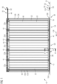
- FIG. 1 to 3 an embodiment of a side sectional door 10 is shown.
- the side sectional door 10 has a door leaf 16 and a guide device 32 for guiding the door leaf 16 between the illustrated closed position and an open position.
- the door leaf 16 has a plurality of slats or panels 22 articulated to one another. In the illustrated embodiment, a total of 5 panels 22a-22e are provided. The number of panels 22 and their width can vary depending on the width of the door opening 34 to be closed.
- the guide device 32 has an upper guide 36 and a lower guide 38 and a first straight section 40 in the area of the closed position, a second straight section 42 in the area of the open position and a curved section 44 between the straight sections 40, 42.
- the door leaf 16 is suspended from the upper guide 36 with roller carriages.
- the lower area of the door leaf 16 is guided in/or on the lower guide 38 .
- the side sectional door 10 has a sealing device 12 for sealing a floor gap 14 between the door leaf 16 and the floor 18 of the door opening 34 to be closed by the door leaf 16 .
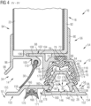
- the sealing device 12 is more precisely in figure 4 shown, which is an enlarged sectional view taken along the line IV-IV of figure 1 shows.
- the sealing device 12 has a bottom seal 46 that can be attached to the door leaf 16 .
- the floor seal 46 extends over several of the panels 22. In the illustrated embodiment, the floor seal 46 extends over all of the panels 22, 22a-22e of the door leaf 16 and thus from the left in figure 1 illustrated end of the door leaf 16 in the area of the closing edge 50 up to the figure 1 illustrated end of the door leaf 16 in the area of the opening edge 52.
- a seal fastening device 56 for fastening the continuous floor seal 46 to the respective panel 22a-22e is provided on the respective lower region 54 of each panel 22a-22e.
- the sealing device 12 also has a threshold formation 58 which can be fastened in a stationary manner to the floor 18 and which forms the lower guide 38 at least in the area of the door opening 34 .
- a threshold formation 58 which can be fastened in a stationary manner to the floor 18 and which forms the lower guide 38 at least in the area of the door opening 34 .
- an essentially identically designed threshold formation 58 is also provided on the second straight section 42 in order to also form the lower guide 38 in the region of the open position.
- the bottom seal 46 preferably has a first sealing lip 60 and a second sealing lip 62 forming a channel 64 therebetween.
- the floor seal 46 has a fastening section 66 and sealing strips 68, 70 which brace away from the respective longitudinal edges of the fastening section 66, the sealing strips 68, 70 forming the sealing lips 60 and 62, respectively.
- the fastening section 66 has a fastening strip 72 which, in the exemplary embodiment shown, essentially has a T-shaped cross section with a thinner neck 74 and a thickening 76 for form-fitting engagement in a complementary fastening receptacle 78 of the respective seal fastening device 56 .
- the fastening section 66 has a connecting web 80 between the first and the second sealing lip 60, 62.
- the connecting web 80 can have different shapes.
- the connecting web 80 is designed to run obliquely upwards, starting from the center and looking towards the two longitudinal edges, so that the connecting web 80 overall has a cross section in the form of a downward-pointing arrowhead.
- the transition area between the connecting web 80 and the respective sealing strip 68, 70 is provided with a material weakening, in particular an area of thinner material thickness 81.
- the sealing strips 68, 70 are provided with a plurality of sealing beads 82 which protrude into the channel 64 inside.
- the sealing beads 82 form a sliding area 84, while the fastening section 66 and the outer area of the sealing strips 68, 70 forming the sealing lips 60, 62 form a main seal body 86.
- the gasket main body 86 and the sliding portion 84 are made of different materials. While the material of the gasket main body 86 is selected in view of good flexibility upon bending of the bottom seal 46, the material of the sliding portion 84 is selected in view of low sliding resistance and higher abrasion resistance. Suitable materials are PE for the seal main body and HDPE for the sliding area 84.
- the seal fastening device 56 has a panel end profile 88 and a seal carrier profile 90 in each case.
- the seal carrier profile 90 is detachably attached to the panel end profile 88 and has the attachment receptacle 78 for the floor seal 46 .
- the panel end profile 88 is firmly attached to the respective lower area of the associated panel 22, 22a-22e.
- the panel end profile 88 is designed as an end angle and/or shaped in such a way that it encloses the lower area of the panel 22 with a U-profile section 92 .
- a downwardly directed flange 96 is provided on an outwardly directed outer side 94 of the panel terminating profile 88 when used as intended, the free end of which is inclined outwardly at an angle. This outward bevel forms a drip ledge 98.
- the sealing lips can be easily bent relative to the connecting web 80 in this area.
- a first clip connection element 100 of a clip connection 102 for connecting the panel end profile 88 and the seal carrier profile 90 is provided on a lower side on a web area of the U-profile section 92 .
- a second clip connection element 104 of the clip connection 102 is provided on the seal carrier profile 90 .
- the first clip connection element 100 is designed as a receiving slot 106 for receiving the second clip connection element 104 designed as a plug strip 108 .
- a lip seal attachment 110 is also provided on the panel end profile 88, to which a lip seal 30 is attached.
- the lip seal 30 is not continuous, rather a separate lip seal 30 is provided continuous across the panel 22 on each panel 22a-22e.
- the seal carrier profile 90 has the second clip connection element 104, for example in the form of the plug-in strip 108, and the fastening receptacle 78.
- the attachment receptacle 78 is provided at the bottom of a channel formation 114 that is open at the bottom.
- the seal carrier profile 90 is provided with a first channel wall 116 and a second channel wall 118, between which the fastening receptacle 78 is formed.
- the first channel wall 116 limits movement of the first sealing strip and the second Channel wall 118 limits a movement of the second sealing strip 70.
- the channel formation 114 with the channel 64 of the floor seal 46 form a recess formation 120, in which a complementary projection formation 122 of the threshold formation 58 can positively engage in order to guide the lower area of the door leaf 16.
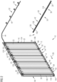
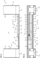
- 4 shows the cross section through the sealing device 12 along the line IV-IV of FIG 1 with the door leaf closed 16; 6 shows a view of the sectional door 10 with the door leaf 16 open from the outside; and 6 shows a plan view of the sectional door 10 with the door leaf 16 open in the area of the door opening 34, with the threshold formation 58 being shown from above.
- the sill formation 58 has a slide strip or slide rail 124 projecting upwards.
- This slide rail 124 forms at least part of the projection formation 122 and is designed in such a way that, when used as intended, it engages in the recess formation 120 in a form-fitting manner in order to guide the lower region of the door leaf 16 .
- the slide rail 124 extends along the door opening 34, to the extent that it can be moved when the door leaf 16 is in the closed position--as in FIGS Figures 1 to 3 shown - continuously engages the recess formation 120 over several panels 22 .
- the continuous floor seal 46 thus encompasses the slide rail 124 on the undersides of several adjacent panels 22.
- the slide rail 124 extends from the left in the closed position 1 viewed continuously through all panels 22a-22d with the exception of the last panel 22e in the closing direction 126, which when the door leaf 16 is closed is the last to be pivoted over the curved section 44 and transferred into the closed position.
- the side sectional door 10 has a frame 128 with a first frame bar 130, against which the door leaf 16 moves when closing and which thus has the counter-closing edge 132, and a second frame bar 132, which is arranged in the area of the curved section 44 .
- the slide rail 124 is guided up to the first frame bar 130, but not up to the second frame bar 134; rather, an inlet region 136 is provided between the second frame bar 134 and the slide rail 124.
- the threshold formation 58 is lower than in the area of the slide rail 124.
- a run-in rail 138 is provided in the run-in area 136 for the transition to the slide rail 124 .
- the entry rail 138 has at least one entry slope 140, 141, 142. How from the Figures 5 and 6 visible in the illustrated embodiment of the inlet rail 138 is a first horizontally extending inlet slope 140, a second inlet slope 141 which runs vertically and is directed inwards and a third inlet slope 142 which is vertical and directed outwards.
- the sill formation 58 also has a floor rail 28 in the form of a floor rail profile 146 .
- the bottom rail 28 has an upwardly opening slide rail receiving channel 148 and/or a downwardly directed rail seal receiving channel 150 .
- the slide rail receiving channel 148 and the rail seal receiving channel 150 are offset from one another in the direction of the width of the bottom rail 28 at different areas of the bottom rail 28 .
- the floor rail 28 has a support area 152, 153 both on the inside and on the outside. At the transition between the respective support area 152, 153 and the area where the receiving channel 148, 150 provided for the slide rail or the rail seal, an inclined surface 156, 158 is provided in each case.
- the slide rail receiving channel 148 has channel walls 160 that protrude obliquely inwards and upwards and a base profile area 162 which forms the bottom of the slide rail receiving channel 148 .
- a floor attachment device 164 for attaching the floor rail 28 to the floor 18 is provided on the base profile area 162 .
- the floor attachment device 164 has through openings (not shown) for attachment screws (not shown) distributed over the length of the floor rail 28 .
- the rail seal 168 has a first and second sealing lip region 170, 172 which can deviate outwards or inwards when the floor rail 28 is pressed onto the floor and are thus pressed elastically against the floor 18.
- the slide rail 124 is trapezoidal in cross section in such a way that it is narrower at the top than at the bottom.
- the slide rail 124 is designed in the form of a slide rail profile 172 .
- the slide rail profile 172 is designed as a trapezoidal U-profile with slide rail legs 173, 174 directed obliquely outwards and a slide rail connecting web 176.
- the slide rail 124 and the bottom rail 28 are detachably connected to one another by a clip connection 180 .
- the entry rail 138 is accommodated in the slide rail receiving channel 148, and the slide rail receiving channel 148 is also covered there by a cover profile 182.
- the cover profile 182 and the run-in rail 138 can be made in one piece or as separate elements.
- the individual profiles 88, 90, 146, 172, 182 are preferably designed as extruded profiles made of a light metal, in particular an aluminum material.
- the bottom rail 28 is provided continuously over the entire width of the door opening 34 .
- the frame bars 130, 134 have frame feet 184, 186 made of a suitable easily formable material, in particular plastic, which receive the contour of the threshold formation 58 present on the respective frame bar 130, 134 and extend it a little.
- the bottom seal 46 and the entire recess formation 120 extends at the closing edge 50 somewhat beyond a metal area of the first panel 22a and can thus be pushed over the corresponding contour formation on the frame foot 184 .
- sealing devices Also located between the frame feet 184, 186 and the bottom rail and/or between the frame foot 184, 186 and the bottom 18 are sealing devices (not shown) for sealing the gaps present here.
- the sill formation 58 has an overall height which does not exceed 20 mm. Furthermore, due to the inclined surfaces 154, 155, 156, 158, 173, 174, the threshold formation 58 can easily be driven over by a vehicle, even with wheels with a small diameter.
- the lip seal 30 rests against the outer inclined surface 158 .
- the sealing strips 68 , 70 each bear against the slide rail 124 with at least one sealing bead 82 .
- the sealing strips 68, 70 hang further towards one another and downwards by gravity and/or by elastic prestressing hanging, so that the sealing beads 82 rest on the free longitudinal edges of the sealing strips 68, 70 on the floor rail 28 and/or the run-in rail 138 and/or the cover profile 182 and thus also seal the floor gap 14 in this area.
- the frame 128 with the frame bars 130, 134 and the guide device 32 are first attached to the door opening 34.
- the threshold training 58 as in the Figures 5 and 6 shown mounted in that first the floor rail 28 is fastened, still without the slide rail 124, to the floor by means of the floor fastening device 164 for screwing.
- the screw heads can be manipulated through the slide rail receiving channel 148, which is then open.
- the length of the slide rail 124 and thus the distance of the slide rail 124 from the second frame bar 134 or the width of the entry area 136 is selected according to the movement profile of the last panel 22e in the closing direction.
- the last panel 22e in the closing direction is guided on a separate guide (not shown) and pivoted more than the other panels. In this case, a larger width should be selected for the inlet area.
- there is enough space on the side of the second frame bar 134 so that all panels 22 can be guided on the same curve of the curve section 44 .
- a large part of the pivoting movement takes place in all panels 22a-22e before the panel 22 moves into the first straight section 40 of the guide device 32, so that the entry area 136 can be selected to be shorter.
- the sliding rail 124, the entry rail 138 and the cover profile 182 can then be clipped into the other floor rail 28 in the area of the open position.
Landscapes
- Engineering & Computer Science (AREA)
- Civil Engineering (AREA)
- Structural Engineering (AREA)
- Mechanical Engineering (AREA)
- Specific Sealing Or Ventilating Devices For Doors And Windows (AREA)
Applications Claiming Priority (1)
| Application Number | Priority Date | Filing Date | Title |
|---|---|---|---|
| DE102018100085.5A DE102018100085A1 (de) | 2018-01-03 | 2018-01-03 | Dichtvorrichtung und damit versehenes Sektionaltor |
Publications (3)
| Publication Number | Publication Date |
|---|---|
| EP3508680A1 EP3508680A1 (de) | 2019-07-10 |
| EP3508680C0 EP3508680C0 (de) | 2023-08-02 |
| EP3508680B1 true EP3508680B1 (de) | 2023-08-02 |
Family
ID=64901433
Family Applications (1)
| Application Number | Title | Priority Date | Filing Date |
|---|---|---|---|
| EP18215761.0A Active EP3508680B1 (de) | 2018-01-03 | 2018-12-21 | Dichtvorrichtung und damit versehenes sektionaltor |
Country Status (3)
| Country | Link |
|---|---|
| EP (1) | EP3508680B1 (pl) |
| DE (1) | DE102018100085A1 (pl) |
| PL (1) | PL3508680T3 (pl) |
Families Citing this family (7)
| Publication number | Priority date | Publication date | Assignee | Title |
|---|---|---|---|---|
| CN110397375A (zh) * | 2019-07-05 | 2019-11-01 | 广东怡发门窗科技有限公司 | 一种抗风压门窗 |
| EP4143408B1 (en) * | 2020-05-01 | 2026-01-07 | Clopay Corporation | Laminate panel with universal fabric hinge for an overhead sectional door |
| DE102021132767A1 (de) * | 2021-12-11 | 2023-06-15 | HYMER GmbH & Co. KG | Freizeitfahrzeug mit einem Raumtrenner für eine Sanitärzelle |
| US12312858B2 (en) * | 2022-04-26 | 2025-05-27 | Arconic Technologies Llc | Water evacuation system for façade systems |
| US12071809B2 (en) | 2022-08-11 | 2024-08-27 | Overhead Door Corporation | Universal seal for a movable barrier |
| US20240344377A1 (en) * | 2022-10-12 | 2024-10-17 | Kohler Co. | Removable Center Guide for Shower Doors |
| CN119419606B (zh) * | 2025-01-06 | 2025-04-08 | 浙江北岛科技有限公司 | 一种多功能电能计量箱 |
Citations (2)
| Publication number | Priority date | Publication date | Assignee | Title |
|---|---|---|---|---|
| EP1057961B1 (de) * | 1999-05-31 | 2005-01-26 | Gretsch Unitas GmbH Baubeschläge | Schwellenprofil für Gebäudetüren sowie Gebäudetür |
| FR2898148B3 (fr) * | 2006-03-02 | 2008-01-25 | Louage & Wisselinck | Porte sectionnelle |
Family Cites Families (11)
| Publication number | Priority date | Publication date | Assignee | Title |
|---|---|---|---|---|
| EP0443306A1 (de) * | 1990-02-20 | 1991-08-28 | Lindpointner Tore Gesellschaft M.B.H. | Schiebetor |
| DE4325698C2 (de) * | 1993-07-30 | 1999-12-02 | Hoermann Kg | Nebentür |
| DE9318718U1 (de) | 1993-12-07 | 1994-04-07 | Guttmann Torsysteme GmbH & Co. KG, Güssing | Seitensektionaltor |
| DE10248608B4 (de) | 2002-09-19 | 2010-10-07 | Novoferm Gmbh | Seitensektionaltor mit elektrischem Torantrieb |
| AT13115U1 (de) | 2006-06-19 | 2013-06-15 | Guttomat Sektionaltore Gmbh | Sektionaltor |
| AT504558B1 (de) | 2006-12-14 | 2014-02-15 | Guttomat Sektionaltore Gmbh | Seitensektionaltor |
| FR2926105B1 (fr) * | 2008-01-08 | 2009-12-25 | Norsk Hydro As | Profile isolant pour ouvrant de chassis coulissant, profile de construction et chassis comportant un tel profile isolant |
| EP2381056B1 (de) | 2010-04-20 | 2018-05-23 | ASSA ABLOY Entrance Systems AB | Bodenführung für ein Seitensektionaltor |
| DE102010043821A1 (de) | 2010-11-12 | 2012-05-16 | Hörmann KG Amshausen | Verriegelungseinrichtung für ein Seitensektionaltor |
| EP2589729B1 (de) | 2011-11-04 | 2014-07-16 | Hörmann Kg Amshausen | Garagentorgriff mit elektrischem Signalgeber zum Betätigen eines Seiten-Sektionaltores |
| US10385600B2 (en) * | 2016-05-11 | 2019-08-20 | Contour Closures, Inc. | Horizontal garage door assembly |
-
2018
- 2018-01-03 DE DE102018100085.5A patent/DE102018100085A1/de not_active Ceased
- 2018-12-21 PL PL18215761.0T patent/PL3508680T3/pl unknown
- 2018-12-21 EP EP18215761.0A patent/EP3508680B1/de active Active
Patent Citations (2)
| Publication number | Priority date | Publication date | Assignee | Title |
|---|---|---|---|---|
| EP1057961B1 (de) * | 1999-05-31 | 2005-01-26 | Gretsch Unitas GmbH Baubeschläge | Schwellenprofil für Gebäudetüren sowie Gebäudetür |
| FR2898148B3 (fr) * | 2006-03-02 | 2008-01-25 | Louage & Wisselinck | Porte sectionnelle |
Also Published As
| Publication number | Publication date |
|---|---|
| EP3508680A1 (de) | 2019-07-10 |
| EP3508680C0 (de) | 2023-08-02 |
| DE102018100085A1 (de) | 2019-07-04 |
| PL3508680T3 (pl) | 2024-02-12 |
Similar Documents
| Publication | Publication Date | Title |
|---|---|---|
| EP3508680B1 (de) | Dichtvorrichtung und damit versehenes sektionaltor | |
| DE10259924A1 (de) | Schiebetüranlage | |
| DE202016102808U1 (de) | Möbel mit einem an einem Laufprofil verfahrbaren Schiebeelement und einer Führungseinrichtung | |
| EP3055475A1 (de) | Schiebetür oder schiebefenster | |
| EP2767652A2 (de) | Absturzsicherung auf Dächern | |
| DE2329263B2 (de) | Schwellenlose, druck- und gasdichte Personen- und/oder Fahrzeugpassage | |
| DE2911728A1 (de) | Faltwand fuer bade- oder duschwannen | |
| EP0978622B1 (de) | Verfahrbare Türflügelanordnung | |
| EP1262625A2 (de) | Thermisch getrennte Regenschutzschiene oder Bodenschwelle | |
| CH684425A5 (de) | Seitensektionaltor oder Rundlauftor sowie Deckensektionaltor. | |
| EP3203006B1 (de) | Dichtungsprofil für eine tür | |
| EP3792444B1 (de) | Befestigungsprofil für eine bodendichtung einer torblattlamelle, torblattbodenlamelle sowie damit ausgestattetes tor | |
| DE19808847A1 (de) | Tür- oder Fensterbeschlag | |
| DE202007019187U1 (de) | Sektionaltor | |
| DE29519952U1 (de) | Rolladenkasten für eine Gebäudeöffnung | |
| DE29803656U1 (de) | Tür- oder Fensterbeschlag | |
| DE102020106365A1 (de) | Bodenschwelle | |
| DE4226702C2 (de) | Dichtungsvorrichtung für den unteren Spalt einer Tür | |
| EP3045647B1 (de) | Schwelle für eine gebäudeschiebetür und rahmenprofil | |
| EP3978715B1 (de) | Dichtungskonzept für ein torblatt, sowie ein verfahren zur anwendung des dichtungskonzeptes | |
| EP4026979B1 (de) | Hermetische türanlage | |
| DE29610889U1 (de) | Sektionaltor | |
| EP0450265B1 (de) | Kantenbekleidung für dünne Fensterbänke | |
| DE102020103603B4 (de) | Hochwasserbeständiges Sektionaltor | |
| EP0311757A1 (de) | Führungsprofil für Schiebetür, Verfahren zu dessen Herstellung und Anwendung des Verfahrens |
Legal Events
| Date | Code | Title | Description |
|---|---|---|---|
| PUAI | Public reference made under article 153(3) epc to a published international application that has entered the european phase |
Free format text: ORIGINAL CODE: 0009012 |
|
| STAA | Information on the status of an ep patent application or granted ep patent |
Free format text: STATUS: THE APPLICATION HAS BEEN PUBLISHED |
|
| AK | Designated contracting states |
Kind code of ref document: A1 Designated state(s): AL AT BE BG CH CY CZ DE DK EE ES FI FR GB GR HR HU IE IS IT LI LT LU LV MC MK MT NL NO PL PT RO RS SE SI SK SM TR |
|
| AX | Request for extension of the european patent |
Extension state: BA ME |
|
| STAA | Information on the status of an ep patent application or granted ep patent |
Free format text: STATUS: REQUEST FOR EXAMINATION WAS MADE |
|
| 17P | Request for examination filed |
Effective date: 20191202 |
|
| RBV | Designated contracting states (corrected) |
Designated state(s): AL AT BE BG CH CY CZ DE DK EE ES FI FR GB GR HR HU IE IS IT LI LT LU LV MC MK MT NL NO PL PT RO RS SE SI SK SM TR |
|
| GRAP | Despatch of communication of intention to grant a patent |
Free format text: ORIGINAL CODE: EPIDOSNIGR1 |
|
| STAA | Information on the status of an ep patent application or granted ep patent |
Free format text: STATUS: GRANT OF PATENT IS INTENDED |
|
| RIC1 | Information provided on ipc code assigned before grant |
Ipc: E06B 1/70 20060101ALN20221118BHEP Ipc: E05D 15/12 20060101ALI20221118BHEP Ipc: E05D 15/06 20060101ALI20221118BHEP Ipc: E06B 3/48 20060101ALI20221118BHEP Ipc: E06B 7/23 20060101AFI20221118BHEP |
|
| INTG | Intention to grant announced |
Effective date: 20221212 |
|
| GRAJ | Information related to disapproval of communication of intention to grant by the applicant or resumption of examination proceedings by the epo deleted |
Free format text: ORIGINAL CODE: EPIDOSDIGR1 |
|
| STAA | Information on the status of an ep patent application or granted ep patent |
Free format text: STATUS: REQUEST FOR EXAMINATION WAS MADE |
|
| GRAP | Despatch of communication of intention to grant a patent |
Free format text: ORIGINAL CODE: EPIDOSNIGR1 |
|
| INTC | Intention to grant announced (deleted) | ||
| RIC1 | Information provided on ipc code assigned before grant |
Ipc: E06B 1/70 20060101ALN20230209BHEP Ipc: E05D 15/12 20060101ALI20230209BHEP Ipc: E05D 15/06 20060101ALI20230209BHEP Ipc: E06B 3/48 20060101ALI20230209BHEP Ipc: E06B 7/23 20060101AFI20230209BHEP |
|
| STAA | Information on the status of an ep patent application or granted ep patent |
Free format text: STATUS: GRANT OF PATENT IS INTENDED |
|
| INTG | Intention to grant announced |
Effective date: 20230316 |
|
| GRAS | Grant fee paid |
Free format text: ORIGINAL CODE: EPIDOSNIGR3 |
|
| GRAA | (expected) grant |
Free format text: ORIGINAL CODE: 0009210 |
|
| STAA | Information on the status of an ep patent application or granted ep patent |
Free format text: STATUS: THE PATENT HAS BEEN GRANTED |
|
| AK | Designated contracting states |
Kind code of ref document: B1 Designated state(s): AL AT BE BG CH CY CZ DE DK EE ES FI FR GB GR HR HU IE IS IT LI LT LU LV MC MK MT NL NO PL PT RO RS SE SI SK SM TR |
|
| REG | Reference to a national code |
Ref country code: GB Ref legal event code: FG4D Free format text: NOT ENGLISH |
|
| REG | Reference to a national code |
Ref country code: CH Ref legal event code: EP |
|
| REG | Reference to a national code |
Ref country code: DE Ref legal event code: R096 Ref document number: 502018012844 Country of ref document: DE |
|
| REG | Reference to a national code |
Ref country code: IE Ref legal event code: FG4D Free format text: LANGUAGE OF EP DOCUMENT: GERMAN |
|
| U01 | Request for unitary effect filed |
Effective date: 20230817 |
|
| U07 | Unitary effect registered |
Designated state(s): AT BE BG DE DK EE FI FR IT LT LU LV MT NL PT SE SI Effective date: 20230823 |
|
| U20 | Renewal fee for the european patent with unitary effect paid |
Year of fee payment: 6 Effective date: 20231214 |
|
| PG25 | Lapsed in a contracting state [announced via postgrant information from national office to epo] |
Ref country code: GR Free format text: LAPSE BECAUSE OF FAILURE TO SUBMIT A TRANSLATION OF THE DESCRIPTION OR TO PAY THE FEE WITHIN THE PRESCRIBED TIME-LIMIT Effective date: 20231103 |
|
| PG25 | Lapsed in a contracting state [announced via postgrant information from national office to epo] |
Ref country code: IS Free format text: LAPSE BECAUSE OF FAILURE TO SUBMIT A TRANSLATION OF THE DESCRIPTION OR TO PAY THE FEE WITHIN THE PRESCRIBED TIME-LIMIT Effective date: 20231202 |
|
| PG25 | Lapsed in a contracting state [announced via postgrant information from national office to epo] |
Ref country code: RS Free format text: LAPSE BECAUSE OF FAILURE TO SUBMIT A TRANSLATION OF THE DESCRIPTION OR TO PAY THE FEE WITHIN THE PRESCRIBED TIME-LIMIT Effective date: 20230802 Ref country code: NO Free format text: LAPSE BECAUSE OF FAILURE TO SUBMIT A TRANSLATION OF THE DESCRIPTION OR TO PAY THE FEE WITHIN THE PRESCRIBED TIME-LIMIT Effective date: 20231102 Ref country code: IS Free format text: LAPSE BECAUSE OF FAILURE TO SUBMIT A TRANSLATION OF THE DESCRIPTION OR TO PAY THE FEE WITHIN THE PRESCRIBED TIME-LIMIT Effective date: 20231202 Ref country code: HR Free format text: LAPSE BECAUSE OF FAILURE TO SUBMIT A TRANSLATION OF THE DESCRIPTION OR TO PAY THE FEE WITHIN THE PRESCRIBED TIME-LIMIT Effective date: 20230802 Ref country code: GR Free format text: LAPSE BECAUSE OF FAILURE TO SUBMIT A TRANSLATION OF THE DESCRIPTION OR TO PAY THE FEE WITHIN THE PRESCRIBED TIME-LIMIT Effective date: 20231103 |
|
| PG25 | Lapsed in a contracting state [announced via postgrant information from national office to epo] |
Ref country code: ES Free format text: LAPSE BECAUSE OF FAILURE TO SUBMIT A TRANSLATION OF THE DESCRIPTION OR TO PAY THE FEE WITHIN THE PRESCRIBED TIME-LIMIT Effective date: 20230802 |
|
| PG25 | Lapsed in a contracting state [announced via postgrant information from national office to epo] |
Ref country code: SM Free format text: LAPSE BECAUSE OF FAILURE TO SUBMIT A TRANSLATION OF THE DESCRIPTION OR TO PAY THE FEE WITHIN THE PRESCRIBED TIME-LIMIT Effective date: 20230802 Ref country code: RO Free format text: LAPSE BECAUSE OF FAILURE TO SUBMIT A TRANSLATION OF THE DESCRIPTION OR TO PAY THE FEE WITHIN THE PRESCRIBED TIME-LIMIT Effective date: 20230802 Ref country code: ES Free format text: LAPSE BECAUSE OF FAILURE TO SUBMIT A TRANSLATION OF THE DESCRIPTION OR TO PAY THE FEE WITHIN THE PRESCRIBED TIME-LIMIT Effective date: 20230802 Ref country code: SK Free format text: LAPSE BECAUSE OF FAILURE TO SUBMIT A TRANSLATION OF THE DESCRIPTION OR TO PAY THE FEE WITHIN THE PRESCRIBED TIME-LIMIT Effective date: 20230802 |
|
| REG | Reference to a national code |
Ref country code: DE Ref legal event code: R097 Ref document number: 502018012844 Country of ref document: DE |
|
| PLBE | No opposition filed within time limit |
Free format text: ORIGINAL CODE: 0009261 |
|
| STAA | Information on the status of an ep patent application or granted ep patent |
Free format text: STATUS: NO OPPOSITION FILED WITHIN TIME LIMIT |
|
| 26N | No opposition filed |
Effective date: 20240503 |
|
| PG25 | Lapsed in a contracting state [announced via postgrant information from national office to epo] |
Ref country code: MC Free format text: LAPSE BECAUSE OF FAILURE TO SUBMIT A TRANSLATION OF THE DESCRIPTION OR TO PAY THE FEE WITHIN THE PRESCRIBED TIME-LIMIT Effective date: 20230802 |
|
| PG25 | Lapsed in a contracting state [announced via postgrant information from national office to epo] |
Ref country code: MC Free format text: LAPSE BECAUSE OF FAILURE TO SUBMIT A TRANSLATION OF THE DESCRIPTION OR TO PAY THE FEE WITHIN THE PRESCRIBED TIME-LIMIT Effective date: 20230802 |
|
| REG | Reference to a national code |
Ref country code: IE Ref legal event code: MM4A |
|
| PG25 | Lapsed in a contracting state [announced via postgrant information from national office to epo] |
Ref country code: IE Free format text: LAPSE BECAUSE OF NON-PAYMENT OF DUE FEES Effective date: 20231221 |
|
| PG25 | Lapsed in a contracting state [announced via postgrant information from national office to epo] |
Ref country code: IE Free format text: LAPSE BECAUSE OF NON-PAYMENT OF DUE FEES Effective date: 20231221 |
|
| U20 | Renewal fee for the european patent with unitary effect paid |
Year of fee payment: 7 Effective date: 20241218 |
|
| PGFP | Annual fee paid to national office [announced via postgrant information from national office to epo] |
Ref country code: CH Payment date: 20250101 Year of fee payment: 7 |
|
| PG25 | Lapsed in a contracting state [announced via postgrant information from national office to epo] |
Ref country code: CY Free format text: LAPSE BECAUSE OF FAILURE TO SUBMIT A TRANSLATION OF THE DESCRIPTION OR TO PAY THE FEE WITHIN THE PRESCRIBED TIME-LIMIT; INVALID AB INITIO Effective date: 20181221 |
|
| PG25 | Lapsed in a contracting state [announced via postgrant information from national office to epo] |
Ref country code: HU Free format text: LAPSE BECAUSE OF FAILURE TO SUBMIT A TRANSLATION OF THE DESCRIPTION OR TO PAY THE FEE WITHIN THE PRESCRIBED TIME-LIMIT; INVALID AB INITIO Effective date: 20181221 |
|
| PG25 | Lapsed in a contracting state [announced via postgrant information from national office to epo] |
Ref country code: TR Free format text: LAPSE BECAUSE OF FAILURE TO SUBMIT A TRANSLATION OF THE DESCRIPTION OR TO PAY THE FEE WITHIN THE PRESCRIBED TIME-LIMIT Effective date: 20230802 |
|
| REG | Reference to a national code |
Ref country code: CH Ref legal event code: U11 Free format text: ST27 STATUS EVENT CODE: U-0-0-U10-U11 (AS PROVIDED BY THE NATIONAL OFFICE) Effective date: 20260101 |
|
| PGFP | Annual fee paid to national office [announced via postgrant information from national office to epo] |
Ref country code: GB Payment date: 20251216 Year of fee payment: 8 |
|
| PGFP | Annual fee paid to national office [announced via postgrant information from national office to epo] |
Ref country code: CZ Payment date: 20251209 Year of fee payment: 8 |
|
| U20 | Renewal fee for the european patent with unitary effect paid |
Year of fee payment: 8 Effective date: 20251216 |
|
| PGFP | Annual fee paid to national office [announced via postgrant information from national office to epo] |
Ref country code: PL Payment date: 20251208 Year of fee payment: 8 |