EP3045647B1 - Schwelle für eine gebäudeschiebetür und rahmenprofil - Google Patents
Schwelle für eine gebäudeschiebetür und rahmenprofil Download PDFInfo
- Publication number
- EP3045647B1 EP3045647B1 EP15202404.8A EP15202404A EP3045647B1 EP 3045647 B1 EP3045647 B1 EP 3045647B1 EP 15202404 A EP15202404 A EP 15202404A EP 3045647 B1 EP3045647 B1 EP 3045647B1
- Authority
- EP
- European Patent Office
- Prior art keywords
- threshold
- cover
- profile
- threshold profile
- fitting
- Prior art date
- Legal status (The legal status is an assumption and is not a legal conclusion. Google has not performed a legal analysis and makes no representation as to the accuracy of the status listed.)
- Active
Links
- 238000007789 sealing Methods 0.000 claims description 25
- 241001669679 Eleotris Species 0.000 description 9
- 238000009423 ventilation Methods 0.000 description 6
- 206010017577 Gait disturbance Diseases 0.000 description 2
- 238000011109 contamination Methods 0.000 description 2
- 239000011521 glass Substances 0.000 description 2
- 238000004378 air conditioning Methods 0.000 description 1
- 239000011324 bead Substances 0.000 description 1
- 238000004140 cleaning Methods 0.000 description 1
- 238000010276 construction Methods 0.000 description 1
- 230000001419 dependent effect Effects 0.000 description 1
- 230000000694 effects Effects 0.000 description 1
- 229920001971 elastomer Polymers 0.000 description 1
- 239000000806 elastomer Substances 0.000 description 1
- 238000009434 installation Methods 0.000 description 1
- 230000001105 regulatory effect Effects 0.000 description 1
Images


Classifications
-
- E—FIXED CONSTRUCTIONS
- E06—DOORS, WINDOWS, SHUTTERS, OR ROLLER BLINDS IN GENERAL; LADDERS
- E06B—FIXED OR MOVABLE CLOSURES FOR OPENINGS IN BUILDINGS, VEHICLES, FENCES OR LIKE ENCLOSURES IN GENERAL, e.g. DOORS, WINDOWS, BLINDS, GATES
- E06B1/00—Border constructions of openings in walls, floors, or ceilings; Frames to be rigidly mounted in such openings
- E06B1/70—Sills; Thresholds
-
- E—FIXED CONSTRUCTIONS
- E05—LOCKS; KEYS; WINDOW OR DOOR FITTINGS; SAFES
- E05D—HINGES OR SUSPENSION DEVICES FOR DOORS, WINDOWS OR WINGS
- E05D15/00—Suspension arrangements for wings
- E05D15/06—Suspension arrangements for wings for wings sliding horizontally more or less in their own plane
- E05D15/0621—Details, e.g. suspension or supporting guides
- E05D15/066—Details, e.g. suspension or supporting guides for wings supported at the bottom
- E05D15/0665—Details, e.g. suspension or supporting guides for wings supported at the bottom on wheels with fixed axis
-
- E—FIXED CONSTRUCTIONS
- E05—LOCKS; KEYS; WINDOW OR DOOR FITTINGS; SAFES
- E05Y—INDEXING SCHEME ASSOCIATED WITH SUBCLASSES E05D AND E05F, RELATING TO CONSTRUCTION ELEMENTS, ELECTRIC CONTROL, POWER SUPPLY, POWER SIGNAL OR TRANSMISSION, USER INTERFACES, MOUNTING OR COUPLING, DETAILS, ACCESSORIES, AUXILIARY OPERATIONS NOT OTHERWISE PROVIDED FOR, APPLICATION THEREOF
- E05Y2201/00—Constructional elements; Accessories therefor
- E05Y2201/10—Covers; Housings
-
- E—FIXED CONSTRUCTIONS
- E05—LOCKS; KEYS; WINDOW OR DOOR FITTINGS; SAFES
- E05Y—INDEXING SCHEME ASSOCIATED WITH SUBCLASSES E05D AND E05F, RELATING TO CONSTRUCTION ELEMENTS, ELECTRIC CONTROL, POWER SUPPLY, POWER SIGNAL OR TRANSMISSION, USER INTERFACES, MOUNTING OR COUPLING, DETAILS, ACCESSORIES, AUXILIARY OPERATIONS NOT OTHERWISE PROVIDED FOR, APPLICATION THEREOF
- E05Y2800/00—Details, accessories and auxiliary operations not otherwise provided for
- E05Y2800/26—Form or shape
- E05Y2800/27—Profiles; Strips
Definitions
- the present invention relates to a threshold for a sliding building door according to the preamble of claim 1 and a frame profile according to the preamble of claim 14.
- Such thresholds for sliding building doors are known in numerous designs from the prior art. These usually consist of a threshold profile which, when mounted on a building floor, projects upwards and in which a fitting fastened to the building sliding door can be moved, with which the sliding sash of the building sliding door can be moved from an opening that closes the building opening into an open position.
- Such a threshold with an additional profile that fulfills this ramp function is, for example, from the DE 20 2008 004 204 U1 known.
- the additional profile disclosed in this document is attached to the top of a threshold profile in such a way that a guide rail for guiding the sliding door only protrudes from the accessible floor or threshold profile surface so that the passage of the building door meets the legal requirements.
- a sliding building door is known in which a carriage is arranged below a pivotable support arm and in an inner floor area in order to enable a handicapped-friendly construction with a low threshold height.
- the object of the present invention is to provide a threshold for a building sliding door with which the building is accessible for the disabled allows and damage and / or contamination of the guide rail of the sliding door can be prevented.
- the threshold according to the invention and the frame profile according to the invention have a threshold profile with a guide rail for guiding a fitting fastened to the sliding door and a cover which can be detachably fixed to the threshold profile.
- the threshold profile is designed transversely to its longitudinal axis as a cavity open to one side.
- the guide rail is arranged in the cavity of the threshold profile covered by the cover.
- the cover has at least one cover element arranged in the direction of the longitudinal axis of the sleeper profile, a first gap being formed between the sleeper profile and the at least one cover element, through which a fitting part of the fitting can pass.
- the fitting has a fitting neck which extends downward into the interior or cavity of the threshold profile.
- the cover has a plurality of cover elements arranged next to one another in the direction of the longitudinal axis of the threshold profile, first and second end caps being arranged on mutually facing end faces of adjacent cover elements, which in the assembled state are spaced apart from one another by a second gap in which the fitting neck of the Fitting is movable.
- a threshold designed according to the invention it is possible to install the threshold profile recessed in the floor of the building and to use the cover to form at least one gap in which the sliding door fitting, in particular a fitting designed as a parallel, sliding, tilting fitting, an opening and closing movement can execute.
- sealing elements for at least partially sealing the gap are arranged on mutually facing end faces of the end caps.
- the second gap between the mutually facing end faces of the end caps opens into the first gap between an outer edge of the cover extending in the direction of the longitudinal axis of the threshold profile and a first side wall of the threshold profile.
- the second gap is also at least partially sealed at least partially by mutually assigned side edges of the cover with a holding element arranged protruding from the first side wall of the threshold profile.
- the cover of the sleeper can be suspended according to a preferred embodiment variant on a second side wall of the sleeper profile extending in the direction of the longitudinal axis of the sleeper profile.
- a hooking contour extending in the direction of the first side wall preferably a support web and a clamping web designed as an angle piece and forming a groove together with a free end of the second side wall, are preferably formed on the second side wall of the threshold profile.
- a clamping web which extends at an angle downwards from the cover surface of the cover, lies in the groove in the suspended state and a support surface of the cover rests on the support web. This ensures reliable support of the cover on the threshold profile.
- a clamping element can be used on the groove, with which the clamping web can be clamped in the groove in the suspended state.
- the clamping element is particularly preferably designed as a piping seal. In addition to being easy to install, this design variant also stands out also by a noise-reducing, tolerance-compensating and dirt-preventing effect of the clamping element.
- the clamping element has a base body and a spring arm projecting at an angle from the base body in the direction of the cover, the spring arm being accommodated in a groove in an outer surface of the clamping web assigned to the second side wall when the cover is in the suspended state.
- the sealing elements are particularly preferably designed as a brush seal, which engage with one another with their bristles and thus reliably prevent contamination of the interior of the threshold profile. It is also conceivable to design the sealing elements as sealing lips preferably made of an elastomer.
- the cover elements have ventilation slots, which serves in particular to avoid an undesirable flow of cold air along the glass pane of the sliding door of the building.
- the end caps are composed at least in two parts from an upper part and a lower part and can be attached in particular to the cover elements.
- the end face of the first end cap assigned to the second end cap is preferably convex and the end face of the second end cap facing the first end cap is accordingly concave, which results in a continuous movement sequence of the fitting guided along the guide rail arranged in the threshold profile when opening or closing corresponds to the sliding door.
- the threshold profile is formed in one piece with the frame, which further increases the stability of the threshold profile.
- top, bottom, left, right, front, rear, etc. refer exclusively to the exemplary representation and position of the threshold, the threshold profile, the cover, the end caps, the gap and the like selected in the respective figures. These terms are not to be understood as restrictive, that is to say that these references can change as a result of different working positions or the mirror-symmetrical design or the like.
- FIG. 1 is designated by the reference numeral 1, a building sliding door.
- the building sliding door 1 here has a frame, in which fixed field 4 is accommodated in a fixed field frame 41 surrounding it and a sliding sash 3 with a glass pane accommodated in a sash frame 31.
- a threshold 2 extends perpendicular to the window frame 5, which can be recessed in a floor of the building.
- the threshold 2 essentially consists of a preferably approximately U-shaped threshold profile 21, designed to be transverse to its longitudinal axis as a cavity that is open to one side, for receiving a fitting 8 fastened to the sliding door 1, shown for example in FIG Figure 5 , and a cover 7 which can be detachably fixed to the threshold profile 21 and with which the threshold profile 21 can be closed.
- the fitting 8 is preferably firmly attached to an outside of the sash frame 31 facing the sill 2 and has a fitting neck 81 which extends vertically downward from a guide housing 6 on the sash frame 31 into the interior or cavity of the sill profile 21.
- a fitting neck 81 which extends vertically downward from a guide housing 6 on the sash frame 31 into the interior or cavity of the sill profile 21.
- an underfloor carriage 82 which can be moved along a guide rail 231 which projects from a floor 23 or is formed thereon and projects into the cavity of the sleeper profile 21.
- the fitting 8 is preferably designed as a parallel-slide-tilt-fitting for a parallel-slide-tilt-door.
- the cover 7 has, as in the Figures 2 to 4 is shown, several cover elements 71 arranged next to one another in the direction x of the longitudinal axis of the threshold profile 21.
- first and second end caps 72, 73 are arranged on mutually facing end faces 715, 716 adjacent cover elements 71. These adjacent end caps 72, 73 are separated from one another in the assembled state by a second gap 11, in which the fitting neck 81 of the fitting can be moved.
- the cover elements 71 and the end caps 72, 73 are, for example in FIG Figure 3 shown, preferably of triangular shape or trapezoidal shape with two parallel side flanks, a tread 711 facing the sash frame 31 and a support surface 712 connecting the two side surfaces 713, 714 at an angle to the tread surface 711.
- the side flank close to the sash frame 31 is configured somewhat wider than the side flank remote from the sash frame 31 serves to fix the cover 7 on a second side wall 24 of the threshold profile 21.
- the cover elements 71 and the first end cap 72 and the second end cap 73 are hung on a clamping web 242 of the second side wall 24.
- a support web 241 extending in the direction of the first side wall 24 and a clamping web 242 formed as an angle piece and together with a free end 244 of the second side wall 24 are formed on the second side wall 24 of the threshold profile 21.
- clamping web 718 which extends angularly downward from the tread surface 711 of the cover 7, while the support surfaces 712, 722, 732 of the cover 7 rest on the support web 241.
- the free end of the support surface 712, 722, 732 presses against the second side wall 24 in the assembled state and thus ensures a stable mounting of the cover elements 71 and the end caps 72, 73 on the second side wall 24 of the threshold profile 21.
- grooves 713 are formed on the narrow end faces of the cover elements 71, in which sealing elements 9 for at least partially sealing a first gap between an outer edge of the cover 7 and a first side wall 22 extending in the direction x of the longitudinal axis of the threshold profile 21 of the threshold profile 21 are included.
- the second gap 11 between the mutually facing end faces 725, 736 of the end caps 72, 73 opens into the first gap 13 between the outer edge of the cover 7, which extends in the direction x of the longitudinal axis of the threshold profile 21, and the first side wall 22 of the threshold profile 21.
- Such sealing elements 9 for at least partially sealing the second gap 11 are also arranged on the mutually facing end faces 725, 736 of the end caps 72, 73.
- the sealing elements 9 are also accommodated on the end caps 72, 73 in t-shaped grooves provided therefor.
- the sealing elements 9 are preferably designed as brush seals, the brushes 92 being held together on a sealing foot 91.
- the sealing foot has a cross-sectional contour corresponding to the groove 713.
- the cover elements 71 are preferably formed in one piece.
- the first end cap 72 and the second end cap 73 are preferably composed of several parts, at least in two parts, from an upper part 721, 731 and a lower part 722, 732.
- the end caps 72, 73 can preferably be plugged onto the end faces 715, 716 of the cover elements 71.
- receiving grooves 717 are formed on the end faces 715, 716 of the cover elements 71, preferably in the corner regions of the cover elements 71 designed as a hollow profile, into which plug elements 724, 734 formed on the end faces of the end caps can be inserted.
- plug elements 737 and corresponding receiving openings are preferably also provided in order to easily plug a respective upper part 721, 731 with a respective lower part 722, 732 can.
- the contours of the end faces of the end caps 72, 73 which are facing one another are adapted in their contours to the travel path of the fitting neck 81 of the fitting 8, depicting the running-in curve of the fitting.
- the end face 725 of the first end cap 72 facing the second end cap 73 is convex and the end face 736 of the second end cap 73 facing the first end cap 72 is concave.
- a clamping element 10 as is shown in FIGS Figures 5 and 6 is shown. With this clamping element 10, the clamping web 718 can be clamped in the groove 27 in the suspended state and thus prevents the clamping web 718 from slipping out of the groove 27 of the threshold profile 21.
- the clamping element 10 is preferably designed as a piping seal.
- This clamping element 10 essentially consists of a base body 101 and a spring arm 102 protruding at an angle from the base body 101 in the direction of the cover 7 or the cover element 71.
- This spring arm 102 is excluded in the suspended state of the cover 7 in a groove 7181 in an outer surface of the clamping web 718 facing the second side wall 24.
- a bulge 243 or the like is formed on the surface of the clamping web 242 facing the clamping web 718, which lies in the suspended state of the cover 7 in a recess or groove 7182 of the clamping web 718 and thus additionally makes it more difficult for the clamping web 718 to slide out of the groove 181 .
- the sealing elements 9 are received in grooves 26, 713, 723, 733 on mutually facing side edges of the cover 7 and a holding piece 25 protruding from the first side wall 22 of the threshold profile 21.
- the cover elements 71 preferably have ventilation slots which preferably extend in the longitudinal direction x of the cover elements 71, which are used to air-condition the space in front of the window pane.
- a pump is preferably connected laterally in the threshold profile 21, which blows air from the threshold profile 21 through the ventilation slots 74 upwards along the window panes and thereby enables ventilation or air conditioning.
- a dirt trough 12 is arranged in the sleeper profile 21, which covers the floor 23 and a part of the side walls 22, 24 of the sleeper profile 21 and serves to facilitate cleaning work in the sleeper body.
- the dirt tray 12 is preferably locked on the inner sides of the side walls 22, 24 and / or the bottom 23 of the threshold profile 21.
- the threshold profile 21 in one piece with the frame 5 as part of a frame profile. So is for example, it is conceivable to form the second side wall 24 of the threshold profile 21 in one piece on the frame 5 and to fix the bottom 23 and the first side wall 22 of the threshold profile 21 in one piece on the frame 5.
- a first projection 51 and on a horizontal section of the window frame 5 near the second side wall 24 of the threshold profile 21 a second projection 52 is fixed, which seals the wing frame 31 of the sliding sash 3 serve with respect to the frame in the closed position of the sliding sash 3.
- These projections do not project any further than the above-mentioned legal dimension above the tread surface 711 of the cover 7 of the threshold 2.
Landscapes
- Engineering & Computer Science (AREA)
- Mechanical Engineering (AREA)
- Civil Engineering (AREA)
- Structural Engineering (AREA)
- Specific Sealing Or Ventilating Devices For Doors And Windows (AREA)
Description
- Die vorliegende Erfindung betrifft eine Schwelle für eine Gebäudeschiebetür gemäß dem Oberbegriff des Anspruchs 1 sowie ein Rahmenprofil gemäß dem Oberbegriff des Anspruchs 14.
- Solche Schwellen für Gebäudeschiebetüren sind in zahlreichen Ausführungen aus dem Stand der Technik bekannt. Diese bestehen üblicherweise aus einem Schwellenprofil, das auf einem Gebäudeboden montiert nach oben hervorsteht und in dem ein an der Gebäudeschiebetür befestigter Beschlag geführt bewegbar ist, mit dem der Schiebeflügel der Gebäudeschiebetür aus einer die Gebäudeöffnung schließenden in eine Öffnungsstellung verfahrbar ist.
- Problematisch ist, dass diese Schwellen so weit aus dem Fußboden des Gebäudes hervorstehen und dadurch Stolpergefahr besteht, so dass man beim Betreten oder Verlassen des Gebäudes durch diese Gebäudeschiebetür über die Schwelle hinweg steigen muss. Ein Überfahren der Schwelle mit einem Rollstuhl oder einem Rollator ist nur möglich, wenn der Schwelle eine Rampe vorgebaut wird. Eine geringfügige Erhöhung ist jedoch überfahrbar und stellt auch keine Stolpergefahr dar. Die zulässige Höhe einer solchen Erhöhung, die noch als "barrierefrei" angesehen wird, ist dabei vom Gesetzgeber geregelt.
- Eine solche Schwelle mit einem Zusatzprofil, das diese Rampenfunktion erfüllt, ist beispielsweise aus der
DE 20 2008 004 204 U1 bekannt. Das in dieser Druckschrift offenbarte Zusatzprofil wird derart auf der Oberseite eines Schwellenprofils befestigt, dass eine Führungsschiene zur Führung der Schiebetür nur noch soweit aus der befahrbaren Boden- bzw. Schwellenprofilfläche hervorsteht, dass der Durchgang der Gebäudetür die gesetzlichen Vorgaben erfüllt. - Aus der
EP 2 907 952 A1 ist eine Gebäudeschiebetür bekannt, bei der ein Laufwagen unterhalb eines schwenkbaren Tragsarms und in einem inneren Fußbodenbereich angeordnet ist, um eine behindertengerechte Konstruktion mit geringer Schwellenhöhe zu ermöglichen. - Aufgabe der vorliegenden Erfindung ist es, eine Schwelle für eine Gebäudeschiebetür bereitzustellen, mit der ein behindertengerechter Zugang des Gebäudes ermöglicht und eine Beschädigung und/oder Verschmutzung der Führungsschiene der Schiebetür verhinderbar ist.
- Diese Aufgabe wird durch eine Schwelle für eine Gebäudeschiebetür mit den Merkmalen des Anspruchs 1 sowie durch ein Rahmenprofil mit den Merkmalen des Anspruchs 14 gelöst.
- Die erfindungsgemäße Schwelle und das erfindungsgemäße Rahmenprofil weist ein Schwellenprofil mit einer Führungsschiene zur Führung eines an der Schiebetür befestigten Beschlages und eine an dem Schwellenprofil abnehmbar festlegbare Abdeckung auf.
- Das Schwellenprofil ist dabei quer zu seiner Längsachse als zu einer Seite offener Hohlraum ausgebildet. Die Führungsschiene ist in dem durch die Abdeckung abgedeckten Hohlraum des Schwellenprofils angeordnet. Die Abdeckung weist mindestens ein in Richtung der Längsachse des Schwellenprofils angeordnetes Abdeckelement auf, wobei zwischen dem Schwellenprofil und dem mindestens einen Abdeckelement ein erster Spalt ausgebildet ist, der von einem Beschlagteil des Beschlages durchfahrbar ist.
- Der Beschlag weist einen Beschlaghals auf, der sich nach unten in den Innen- oder Hohlraum des Schwellenprofils erstreckt.
- Die Abdeckung weist dabei mehrere in Richtung der Längsachse des Schwellenprofils nebeneinander angeordnete Abdeckelemente auf, wobei an einander zugewandten Stirnseiten benachbarter Abdeckelemente erste und zweite Endkappen angeordnet sind, die im montierten Zustand abständig voneinander durch einen zweiten Spalt voneinander getrennt angeordnet sind, in dem der Beschlaghals des Beschlages verfahrbar ist.
- Mit einer derart ausgebildeten erfindungsgemäßen Schwelle ist es ermöglicht, das Schwellenprofil in den Gebäudeboden versenkt einzubauen und mithilfe der Abdeckung wenigstens einen Spalt auszubilden, in denen der Schiebetürbeschlag, insbesondere ein als Parallel-Abstell-Schiebe-Kipp Beschlag ausgebildeter Beschlag, eine Öffnungs- und Schließbewegung ausführen kann.
- Vorteilhafte Ausführungsvarianten der Erfindung sind Gegenstand der Unteransprüche.
- Gemäß einer weiteren vorteilhaften Ausführungsvariante der Erfindung sind an einander zugewandten Stirnseiten der Endkappen Dichtelemente zur zumindest teilweisen Abdichtung des Spaltes angeordnet.
- Dadurch ist ein die Bewegung des Beschlages beeinträchtigender Eintrag von Schmutz in das Schwellenprofil weitgehend vermeidbar. Die Bewegung des Beschlages zwischen den Dichtelementen wird dabei durch die Dichtelemente nicht behindert.
- Gemäß einer weiteren vorteilhaften Ausführungsvariante der Erfindung mündet der zweite Spalt zwischen den einander zugewandten Stirnseiten der Endkappen in den ersten Spalt zwischen einer sich in Richtung der Längsachse des Schwellenprofils erstreckenden Außenkante der Abdeckung und einer ersten Seitenwand des Schwellenprofils.
- Dadurch ist ein durchgängiger Spalt geschaffen, entlang dem der Beschlag der Schiebetür verfahrbar ist.
- Auch der zweite Spalt wird dabei gemäß einer vorteilhaften Ausführungsvariante der Erfindung zumindest teilweise durch einander zugeordneten Seitenrändern der Abdeckung mit einem aus der ersten Seitenwand des Schwellenprofils hervorstehenden Haltestück angeordneten Dichtelementen zumindest teilweise abgedichtet.
- Insbesondere zur einfachen Montage ist die Abdeckung der Schwelle gemäß einer bevorzugten Ausführungsvariante an einer sich in Richtung der Längsachse des Schwellenprofils erstreckenden zweiten Seitenwand des Schwellenprofils einhängbar.
- Bevorzugt ist dazu an der zweiten Seitenwand des Schwellenprofils ein sich in Richtung der ersten Seitenwand erstreckende Verhakungskontur, bevorzugt ein Stützsteg und ein als Winkelstück ausgebildeter und zusammen mit einem freien Ende der zweiten Seitenwand eine Nut bildender Klemmsteg angeformt. Ein sich von der Deckfläche der Abdeckung winklig nach unten erstreckender Klemmsteg liegt dabei im eingehängten Zustand in der Nut ein und eine Stützfläche der Abdeckung auf dem Stützsteg auf. Dadurch ist eine zuverlässige Abstützung der Abdeckung an dem Schwellenprofil gewährleistet.
- Um das Ein- und Ausbauen der Abdeckung noch weiter zu vereinfachen sowie den Eintrag von Schmutz zu verhindern, ist an der Nut ein Klemmelement einsetzbar, mit dem der Klemmsteg im eingehängten Zustand in der Nut festklemmbar ist. Das Klemmelement ist dabei besonders bevorzugt als Kederdichtung ausgebildet. Neben der einfachen Montierbarkeit zeichnet sich diese Ausführungsvariante auch durch eine geräuschmindernde, toleranzausgleichende und den Eintrag von Schmutz verhindernde Wirkung des Klemmelements aus.
- Das Klemmelement weist dabei gemäß einer besonders bevorzugten Ausführungsvariante einen Grundkörper und einen aus dem Grundkörper in Richtung der Abdeckung winklig abstehenden Federarm auf, wobei der Federarm im eingehängten Zustand der Abdeckung in einer Nut in einer der zweiten Seitenwand zugeordneten Außenfläche des Klemmstegs aufgenommen ist.
- Zur Befestigung der Dichtelemente sind nach einer weiteren bevorzugten Ausführungsvariante aneinander zugewandten Seitenrändern der Abdeckung und einem aus der ersten Seitenwand des Schwellenprofils hervorstehenden Haltestück Aufnahmenuten vorgesehen, in denen die Dichtelemente aufgenommen sind.
- Die Dichtelemente sind dabei besonders bevorzugt als Bürstendichtung ausgebildet, die mit ihren Borsten ineinander greifen und so zuverlässig eine Verschmutzung des Innenraumes des Schwellenprofils verhindern. Denkbar ist auch, die Dichtelemente als bevorzugt aus einem Elastomer bestehende Dichtlippen auszubilden.
- Gemäß einer weiteren besonders bevorzugten Ausführungsvariante weisen die Abdeckungselemente Lüftungsschlitze auf, was insbesondere der Vermeidung einer unerwünschten Kaltluftströmung entlang der Glasscheibe der Gebäudeschiebetür dient.
- Die Endkappen sind gemäß einer Ausführungsvariante der Erfindung zumindest zweiteilig aus einem Oberteil und einem Unterteil zusammengesetzt und insbesondere an die Abdeckungselemente ansteckbar.
- Zur Führung des Beschlages der Schiebetür ist die der zweiten Endkappe zugeordneten Stirnseite der ersten Endkappe bevorzugt konvex und die der ersten Endkappe zugewandte Stirnseite der zweiten Endkappe dementsprechend konkav geformt, was einen kontinuierlichen Bewegungsablauf des entlang der in dem Schwellenprofil angeordneten Führungsschiene geführten Beschlages beim Öffnen beziehungsweise Schließen der Schiebetür entspricht.
- Bei dem Rahmenprofil ist nach einer bevorzugten Ausführungsvariante zumindest ein Teilabschnitt des Schwellenprofils einstückig mit dem Blendrahmen ausgebildet, was die Stabilität des Schwellenprofils noch weiter erhöht.
- Nachfolgend wird eine bevorzugte Ausführungsvariante der Erfindung anhand der beiliegenden Zeichnungen näher erläutert. Es zeigen:
- Figur 1
- eine perspektivische Ansicht einer Gebäudeschiebetür mit einer Ausführungsvariante einer erfindungsgemäßen Schwelle,
- Figur 2
- eine vergrößerte Ansicht der in
Figur 1 gezeigten Schwelle in einer perspektivischen Darstellung, - Figur 3
- eine perspektivische Explosionsdarstellung der Abdeckung der Schwelle,
- Figur 4
- eine weitere Explosionsdarstellung der Abdeckung der Schwelle,
- Figur 5
- eine Querschnittsansicht durch die Schwelle und den Türrahmen der Gebäudeschiebetür,
- Figur 6
- eine Querschnittsansicht eines Details der Schwelle und
- Figur 7
- eine weitere perspektivische Teilansicht der Gebäudeschiebetür mit daran angeordneter Schwelle mit Lüftungsschlitzen versehender Abdeckung.
- In der nachfolgenden Figurenbeschreibung beziehen sich Begriffe wie oben, unten, links, rechts, vorne, hinten usw. ausschließlich auf die in den jeweiligen Figuren gewählte beispielhafte Darstellung und Position der Schwelle, des Schwellenprofils, der Abdeckung, der Endkappen, des Spaltes und dergleichen. Diese Begriffe sind nicht einschränkend zu verstehen, das heißt, durch verschiedene Arbeitsstellungen oder die spiegelsymmetrische Auslegung oder dergleichen können sich diese Bezüge ändern.
- In
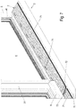
Figur 1 ist mit dem Bezugszeichen 1 insgesamt eine Gebäude-Schiebetür bezeichnet. Die Gebäude-Schiebetür 1 weist hier einen Blendrahmen auf, in dem Festfeld 4 in einem diesen umgebenden Festfeldrahmen 41 aufgenommen ist sowie einen Schiebeflügel 3 mit einer in einem Flügelrahmen 31 aufgenommenen Glasscheibe. Im Bodenbereich der Gebäude-Schiebetür 1 erstreckt sich senkrecht zum Blendrahmen 5 eine Schwelle 2, die in einem Fußboden des Gebäudes versenkt einbaubar ist. - Die Schwelle 2 besteht dabei im Wesentlichen aus einem quer zu seiner Längsachse als zu einer Seite offener Hohlraum ausgebildeten, bevorzugt etwa u-förmigen Schwellenprofil 21 zur Aufnahme eines an der Schiebetür 1 befestigten Beschlages 8, gezeigt beispielsweise in
Figur 5 , sowie einer an dem Schwellenprofil 21 abnehmbar festlegbaren Abdeckung 7, mit der das Schwellenprofil 21 verschließbar ist. - Der Beschlag 8 ist dabei bevorzugt fest an einer der Schwelle 2 zugewandten Außenseite des Flügelrahmens 31 befestigt und weist einen Beschlaghals 81 auf, der sich von einem Führungsgehäuse 6 am Flügelrahmen 31 senkrecht nach unten in den Innen- oder Hohlraum des Schwellenprofils 21 erstreckt. Am vorderen Ende des Beschlaghalses 81 ist bevorzugt eine Unterflurlaufwagen 82 festgelegt, der entlang einer an einem Boden 23 festgelegten oder daran angeformten in den Hohlraum des Schwellenprofil 21 vorstehenden Führungsschiene 231 geführt verfahrbar ist. Bevorzugt ist der Beschlag 8 als Parallel-Abstell-Schiebe-Kipp-Beschlag für eine Parallel-Abstell-Schiebe-Kipp-Tür ausgebildet.
- Die Abdeckung 7 weist, wie in den
Figuren 2 bis 4 gezeigt ist, mehrere in Richtung x der Längsachse des Schwellenprofils 21 nebeneinander angeordnete Abdeckelemente 71 auf. - Dabei sind an einander zugewandten Stirnseiten 715, 716 benachbarten Abdeckelemente 71 erste und zweite Endkappen 72, 73 angeordnet. Diese einander benachbarte Endkappen 72, 73 sind im montierten Zustand abständig voneinander durch einen zweiten Spalt 11, in dem der Beschlaghals 81 des Beschlages verfahrbar ist, voneinander getrennt.
- Die Abdeckelemente 71 und die Endkappen 72, 73 sind, wie beispielsweise in
Figur 3 gezeigt, von bevorzugt dreieckiger Gestalt oder trapezförmiger Gestalt mit zwei parallel zueinander stehenden Seitenflanken, einer dem Flügelrahmen 31 zugewandten Trittfläche 711 und einer winklig zur Trittfläche 711 die beiden Seitenflächen 713, 714 miteinander verbindenden Stützfläche 712. - Die dem Flügelrahmen 31 nahe Seitenflanke ist etwas breiter ausgestaltet als die dem Flügelrahmen 31 ferne Seitenflanke dient dabei der Festlegung der Abdeckung 7 an einer zweiten Seitenwand 24 des Schwellenprofils 21.
- Wie in den
Figuren 3 ,5 und6 gut zu erkennen ist, sind die Abdeckelemente 71 sowie die erste Endkappe 72 und die zweite Endkappe 73 an einem Klemmsteg 242 der zweiten Seitenwand 24 eingehängt. - Dazu ist an der zweiten Seitenwand 24 des Schwellenprofils 21 ein sich in Richtung der ersten Seitenwand 24 erstreckender Stützsteg 241 sowie ein als Winkelstück ausgebildeter und zusammen mit einem freien Ende 244 der zweiten Seitenwand 24 eine Nut 27 bildender Klemmsteg 242 angeformt.
- In dieser Nut 27 liegt dabei ein sich von der Trittfläche 711 der Abdeckung 7 winklig nach unten erstreckender Klemmsteg 718 ein, während die Stützflächen 712, 722, 732 der Abdeckung 7 auf dem Stützsteg 241 aufliegt.
- Das freie Ende der Stützfläche 712, 722, 732 drückt dabei im montierten Zustand gegen die zweite Seitenwand 24 und gewährleistet so eine stabile Halterung der Abdeckelemente 71 und der Endkappen 72, 73 an der zweiten Seitenwand 24 des Schwellenprofils 21.
- Wie in
Figur 3 des Weiteren zu erkennen ist, sind an dem schmalen Stirnflächen der Abdeckelemente 71 Nuten 713 angeformt, in denen Dichtelemente 9 zur zumindest teilweisen Abdichtung eines ersten Spaltes zwischen einer sich in Richtung x der Längsachse des Schwellenprofils 21 erstreckenden Außenkante der Abdeckung 7 und einer ersten Seitenwand 22 des Schwellenprofils 21 aufgenommen sind. - Der zweite Spalt 11 zwischen den einander zugewandten Stirnseiten 725, 736 der Endkappen 72, 73 mündet dabei in den ersten Spalt 13 zwischen der sich in Richtung x der Längsachse des Schwellenprofils 21 erstreckenden Außenkante der Abdeckung 7 und der ersten Seitenwand 22 des Schwellenprofils 21.
- Auch an den einander zugewandten Stirnseiten 725, 736 der Endkappen 72, 73 sind derartige Dichtelemente 9 zur zumindest teilweisen Abdichtung des zweiten Spaltes 11 angeordnet. Die Dichtelemente 9 sind auch an den Endkappen 72, 73 in dafür vorgesehene t-förmigen Nuten aufgenommen.
- Die Dichtelemente 9 sind dabei bevorzugt als Bürstendichtungen ausgebildet, wobei die Bürsten 92 an einem Dichtungsfuß 91 zusammengehalten sind. Der Dichtungsfuß weist dabei eine der Nut 713 entsprechende Querschnittskontur auf.
- Die Abdeckelemente 71 sind bevorzugt einstückig ausgebildet.
- Die erste Endkappe 72 und die zweite Endkappe 73 ist bevorzugt mehrteilig, zumindest zweiteilig aus einem Oberteil 721, 731 und einem Unterteil 722, 732 zusammengesetzt.
- Die Endkappen 72, 73 sind dabei bevorzugt an die Stirnseiten 715, 716 der Abdeckungselemente 71 ansteckbar. Dazu sind an den Stirnseiten 715, 716 der Abdeckungselemente 71 Aufnahmenuten 717 angeformt, vorzugsweise in den Eckbereichen der als Hohlprofil ausgebildeten Abdeckungselemente 71, in die an den Stirnseiten der Endkappen angeformte Steckelemente 724, 734 einsteckbar sind.
- Zum Zusammensetzen des Oberteils 721, 731 mit dem Unterteil 722, 732 der ersten beziehungsweise zweiten Endkappe 72, 73 sind bevorzugt ebenfalls Steckelemente 737 und entsprechende Aufnahmeöffnungen vorgesehen, um ein jeweiliges Oberteil 721, 731 mit einem jeweiligen Unterteil 722, 732 in einfacher Weise zusammenstecken zu können.
- Die einander gewandten Stirnseiten der Endkappen 72, 73 sind dabei in ihrer Kontur an den Fahrweg des Beschlaghalses 81 des Beschlages 8 angepasst, die Einlaufkurve des Beschlages abbildend, ausgebildet. In der hier gezeigten Ausführungsvariante ist die der zweiten Endkappe 73 zugewandte Stirnseite 725 der ersten Endkappe 72 konvex und die der ersten Endkappe 72 zugewandte Stirnseite 736 der zweiten Endkappe 73 konkav geformt.
- Besonders bevorzugt ist in der Nut 27 ein Klemmelement 10 einsetzbar, wie es in den
Figuren 5 und6 gezeigt ist. Mit diesem Klemmelement 10 ist der Klemmsteg 718 im eingehängten Zustand in der Nut 27 festklemmbar und verhindert so ein Herausrutschen des Klemmstegs 718 aus der Nut 27 des Schwellenprofils 21. - Das Klemmelement 10 ist dabei bevorzugt als Kederdichtung ausgebildet. Dieses Klemmelement 10 besteht dabei im Wesentlichen aus einem Grundkörper 101 und einem aus dem Grundkörper 101 in Richtung der Abdeckung 7 beziehungsweise des Abdeckungselements 71 winklig abstehenden Federarms 102.
- Dieser Federarm 102 ist dabei im eingehängten Zustand der Abdeckung 7 in einer Nut 7181 in einer der zweiten Seitenwand 24 zugewandten Außenfläche des Klemmstegs 718 ausgenommen.
- Besonders bevorzugt ist, wie in
Figur 6 gezeigt ist, an der dem Klemmsteg 718 zugewandten Fläche des Klemmstegs 242 eine Wulst 243 oder dergleichen angeformt, die im eingehängten Zustand der Abdeckung 7 in einer Aussparung oder Nut 7182 des Klemmstegs 718 einliegt und so ein Herausgleiten des Klemmstegs 718 aus der Nut 181 zusätzlich erschwert. - Die Dichtelemente 9 sind dabei in Aufnahmenuten 26, 713, 723, 733 an einander zugewandten Seitenrändern der Abdeckung 7 und einem aus der ersten Seitenwand 22 des Schwellenprofils 21 hervorstehenden Haltestück 25 aufgenommen.
- Wie des Weiteren in
Figur 7 gezeigt weisen die Abdeckungselemente 71 bevorzugt Lüftungsschlitze auf, die sich vorzugsweise in Längsrichtung x der Abdeckungselemente 71 erstrecken, die der Klimatisierung des Raums vor der Fensterscheibe dienen. Dazu wird bevorzugt seitlich im Schwellenprofil 21 eine Pumpe angeschlossen, die Luft aus dem Schwellenprofil 21 durch die Lüftungsschlitze 74 hindurch entlang den Fensterscheiben nach oben bläst und dadurch eine Lüftung oder Klimatisierung ermöglicht. - Wie in
Figur 5 des Weiteren gezeigt ist, ist nach der hier gezeigten bevorzugten Ausführungsvariante in dem Schwellenprofil 21 eine Schmutzwanne 12 angeordnet, die den Boden 23 und ein Teilstück der Seitenwände 22, 24 des Schwellenprofils 21 bedeckt und die der Erleichterung von Reinigungsarbeiten im Schwellenkörper dient. Die Schmutzwanne 12 ist dabei bevorzugt an den Innenseiten der Seitwände 22, 24 und/oder des Bodens 23 des Schwellenprofils 21 verrastet. - Denkbar ist auch, zumindest ein Teilabschnitt des Schwellenprofils 21 einstückig mit dem Blendrahmen 5 als Teil eines Rahmenprofils auszubilden. So ist beispielsweise denkbar, die zweite Seitenwand 24 des Schwellenprofils 21 einstückig an dem Blendrahmen 5 anzuformen und den Boden 23 und die erste Seitenwand 22 des Schwellenprofils 21 einstückig am Blendrahmen 5 festzulegen.
- Wie in
Figur 5 gezeigt, ist auf einer der Schwelle 2 abgewandten Seite des Blendrahmens 5 in Fußbodenhöhe ein erster Vorsprung 51 und auf einem der zweiten Seitenwand 24 des Schwellenprofils 21 nahen horizontalen Abschnitt des Blendrahmens 5 ein zweiter Vorsprung 52 festgelegt, die der Abdichtung des Flügelrahmens 31 des Schiebeflügels 3 gegenüber dem Blendrahmen in der Schließstellung des Schiebeflügels 3 dienen. Diese Vorsprünge stehen dabei nicht weiter als das eingangs erwähnte gesetzliche Maß über die Trittfläche 711 der Abdeckung 7 der Schwelle 2 nach oben vor. - Denkbar wäre auch, die Vorsprünge 51, 52 wegzulassen und stattdessen eine Dichtung wie beispielsweise eine Bürstendichtung an der Unterseite des Flügelrahmens 31 des Schiebeflügels 3 anzubringen. Dadurch ist der horizontale Abschnitt des Blendrahmens 5 bündig mit der Trittfläche 711 der Abdeckung 7.
-
- 1
- Gebäude-Schiebetür
- 2
- Schwelle
- 21
- Schwellenprofil
- 22
- erste Seitenwand
- 23
- Boden
- 231
- Führungsschiene
- 24
- zweite Seitenwand
- 241
- Stützsteg
- 242
- Klemmsteg
- 243
- Wulst
- 244
- freies Ende
- 25
- Haltestück
- 26
- Nut
- 27
- Nut
- 3
- Schiebeflügel
- 31
- Flügelrahmen
- 4
- Festfeld
- 41
- Festfeldrahmen
- 5
- Blendrahmen
- 51
- erster Vorsprung
- 52
- zweiter Vorsprung
- 6
- Führungsgehäuse
- 7
- Abdeckung
- 71
- Abdeckelement
- 711
- Trittfläche
- 712
- Stützfläche
- 713
- Nut
- 714
- Nut
- 715
- Stirnseite
- 716
- Stirnseite
- 717
- Nut
- 718
- Klemmsteg
- 7181
- Nut
- 7182
- Nut
- 72
- erste Endkappe
- 721
- Oberteil
- 722
- Unterteil
- 723
- Nut
- 724
- Steckelement
- 725
- Stirnseite
- 726
- Stirnseite
- 727
- Steckelement
- 728
- Klemmsteg
- 73
- zweite Endkappe
- 731
- Oberteil
- 732
- Unterteil
- 733
- Nut
- 734
- Steckelement
- 735
- Stirnseite
- 736
- Stirnseite
- 737
- Steckelement
- 738
- Klemmsteg
- 74
- Lüftungsschlitz
- 8
- Beschlag
- 81
- Beschlaghals
- 82
- Wagen
- 9
- Dichtung
- 91
- Dichtungsfuß
- 92
- Bürsten
- 10
- Klemmelement
- 101
- Grundkörper
- 102
- Federarm
- 11
- zweiter Spalt
- 12
- Schmutzwanne
- 13
- erster Spalt
- x
- Längsrichtung des Schwellenprofils
Claims (14)
- Schwelle (2) für eine Gebäude-Schiebetür (1), aufweisend- ein Schwellenprofil (21) mit einer Führungsschiene (231) zur Führung eines an der Schiebetür befestigten Beschlages (8),- eine an dem Schwellenprofil (21) abnehmbar festlegbare Abdeckung (7),- wobei das Schwellenprofil (21) quer zu seiner Längsachse als zu einer Seite offener Hohlraum ausgebildet ist,- wobei die Führungsschiene (231) in dem durch die Abdeckung (7) abgedeckten Hohlraum des Schwellenprofils (21) angeordnet ist,- wobei die Abdeckung (7) mindestens ein in Richtung (x) der Längsachse des Schwellenprofils (21) angeordnetes Abdeckelement (71) aufweist, wobei zwischen dem Schwellenprofil (21) und dem mindestens einen Abdeckelement (71) ein erster Spalt (13) ausgebildet ist, der von einem Beschlagteil des Beschlages (8) durchfahrbar ist,- wobei der Beschlag (8) einen Beschlaghals (81) aufweist, der sich nach unten in den Innen- oder Hohlraum des Schwellenprofils (21) erstrecktdadurch gekennzeichnet, dass- die Abdeckung (7) mehrere in Richtung (x) der Längsachse des Schwellenprofils (21) nebeneinander angeordnete Abdeckelemente (71) aufweist,- wobei an einander zugewandten Stirnseiten (715, 716) benachbarter Abdeckelemente (71) erste und zweite Endkappen (72, 73) angeordnet sind, die im montierten Zustand abständig voneinander durch einen zweiten Spalt (11) voneinander getrennt angeordnet sind, in dem der Beschlaghals (81) des Beschlages (8) verfahrbar ist.
- Schwelle (2) nach Anspruch 1, dadurch gekennzeichnet, dass an einander zugewandten Stirnseiten (725, 736) der Endkappen (72, 73) Dichtelemente (9) zur zumindest teilweisen Abdichtung des zweiten Spaltes (11) angeordnet sind.
- Schwelle (2) nach Anspruch 1 oder 2, dadurch gekennzeichnet, dass der zweite Spalt (11) zwischen den einander zugewandten Stirnseiten (725, 736) der Endkappen (72, 73) in den ersten Spalt (13) zwischen einer sich in Richtung (x) der Längsachse des Schwellenprofils (21) erstreckenden Außenkante der Abdeckung (7) und einer ersten Seitenwand (22) des Schwellenprofils (21) mündet.
- Schwelle (2) nach einem der vorhergehenden Ansprüche, dadurch gekennzeichnet, dass an einander zugewandten Seitenrändern der Abdeckung (7) und einem aus der ersten Seitenwand (22) des Schwellenprofils (21) hervorstehenden Haltestück (25) Dichtelemente (9) zur zumindest teilweisen Abdichtung des ersten Spaltes (13) angeordnet sind.
- Schwelle (2) nach einem der vorhergehenden Ansprüche, dadurch gekennzeichnet, dass die Abdeckung (7) an einer sich in Richtung (x) der Längsachse des Schwellenprofils (21) erstreckenden zweiten Seitenwand (24) des Schwellenprofils (21) einhängbar ist.
- Schwelle (2) nach Anspruch 5, dadurch gekennzeichnet, dass an der zweiten Seitenwand (24) des Schwellenprofils (21) ein sich in Richtung der ersten Seitenwand (24) erstreckender Stützsteg (241) und ein als Winkelstück ausgebildeter und zusammen mit einem freien Ende (244) der zweiten Seitenwand (24) eine Nut (27) bildender Klemmsteg (242) angeformt ist, wobei ein sich von einer Trittfläche (711) der Abdeckung (7) winklig nach unten erstreckender Klemmsteg (718) im eingehängten Zustand in der Nut (27) einliegt und eine Stützfläche (712) der Abdeckung auf dem Stützsteg (241) aufliegt.
- Schwelle (2) nach Anspruch 6, dadurch gekennzeichnet, dass in der Nut (27) ein Klemmelement (10) einsetzbar ist, mit dem der Klemmsteg (718) im eingehängten Zustand in der Nut (27) festklemmbar ist.
- Schwelle (2) nach den Ansprüchen 2 und 4 und optional zusätzlich einem der vorhergehenden Ansprüche 3 oder 5-7, dadurch gekennzeichnet, dass die Dichtelemente (9) in Aufnahmenuten (26, 713, 723, 733) an einander zugewandten Seitenrändern der Abdeckung (7) und einem aus der ersten Seitenwand (22) des Schwellenprofils (21) hervorstehenden Haltestück (25) aufgenommen sind.
- Schwelle (2) nach den Ansprüchen 2 und 4 und optional zusätzlich einem der vorhergehenden Ansprüche 3 oder 5-8 dadurch gekennzeichnet, dass die Dichtelemente (9) als Bürstendichtung ausgebildet sind.
- Schwelle (2) nach einem der vorhergehenden Ansprüche, dadurch gekennzeichnet, dass die der zweiten Endkappe (73) zugewandte Stirnseite (725) der ersten Endkappe (72) konvex und die der ersten Endkappe (72) zugewandte Stirnseite (736) der zweiten Endkappe (73) konkav geformt ist.
- Schwelle (2) nach einem der vorhergehenden Ansprüche, dadurch gekennzeichnet, dass die Endkappen (72, 73) an die Abdeckungselemente (71) ansteckbar sind.
- Schwelle (2) nach einem der vorhergehenden Ansprüche, dadurch gekennzeichnet, dass in dem Schwellenprofil (21) eine herausnehmbare Schmutzwanne (12) angeordnet ist.
- Schwelle (2) nach einem der vorhergehenden Ansprüche, dadurch gekennzeichnet, dass sie als Schwelle einer Parallel-Abstell-Schiebe-Kipp-Tür ausgebildet ist.
- Rahmenprofil für eine Gebäude-Schiebetür (1), mit einem Blendrahmen (5) und einer Schwelle (2), dadurch gekennzeichnet, dass die Schwelle (2) nach einem der vorhergehenden Ansprüche ausgebildet ist, wobei zumindest ein Teilabschnitt des Schwellenprofils (21) einstückig mit dem Blendrahmen (5) ausgebildet ist.
Applications Claiming Priority (1)
| Application Number | Priority Date | Filing Date | Title |
|---|---|---|---|
| DE102015100586.7A DE102015100586A1 (de) | 2015-01-15 | 2015-01-15 | Schwelle für eine Gebäudeschiebetür und Rahmenprofil |
Publications (2)
| Publication Number | Publication Date |
|---|---|
| EP3045647A1 EP3045647A1 (de) | 2016-07-20 |
| EP3045647B1 true EP3045647B1 (de) | 2020-07-08 |
Family
ID=54936944
Family Applications (1)
| Application Number | Title | Priority Date | Filing Date |
|---|---|---|---|
| EP15202404.8A Active EP3045647B1 (de) | 2015-01-15 | 2015-12-23 | Schwelle für eine gebäudeschiebetür und rahmenprofil |
Country Status (2)
| Country | Link |
|---|---|
| EP (1) | EP3045647B1 (de) |
| DE (1) | DE102015100586A1 (de) |
Families Citing this family (1)
| Publication number | Priority date | Publication date | Assignee | Title |
|---|---|---|---|---|
| JP6802124B2 (ja) * | 2017-08-10 | 2020-12-16 | 三協立山株式会社 | サッシ |
Family Cites Families (6)
| Publication number | Priority date | Publication date | Assignee | Title |
|---|---|---|---|---|
| DE2514292C2 (de) * | 1975-04-02 | 1985-02-28 | H. Jos. Trimborn Söhne Inh. Gottlieb Müller, 5300 Bonn | Abdeckung für eine Bodenrinne |
| DE19920534C1 (de) * | 1999-05-05 | 2000-08-31 | Alu Kaupp Gmbh | Profilschiene für die Bautechnik |
| DE202008004204U1 (de) | 2008-03-26 | 2008-07-03 | Gretsch-Unitas GmbH Baubeschläge | Schwelle für Gebäudetüren sowie Zusatzprofil zur Verwendung bei einer Schwelle bzw. einem Schwellenprofil für Gebäudetüren |
| DE202009014785U1 (de) * | 2009-11-02 | 2010-12-30 | Blösch, Dieter | Schiebetür |
| DE102011053804B4 (de) * | 2011-09-20 | 2015-02-19 | Hautau Gmbh | Wasserdichte Laufschiene für einen Schiebeflügel (Verfahren und Vorrichtung) |
| DE202014100685U1 (de) * | 2014-02-17 | 2015-05-20 | Raico Bautechnik Gmbh | Schiebefenster oder Schiebetür |
-
2015
- 2015-01-15 DE DE102015100586.7A patent/DE102015100586A1/de not_active Withdrawn
- 2015-12-23 EP EP15202404.8A patent/EP3045647B1/de active Active
Non-Patent Citations (1)
| Title |
|---|
| None * |
Also Published As
| Publication number | Publication date |
|---|---|
| EP3045647A1 (de) | 2016-07-20 |
| DE102015100586A1 (de) | 2016-07-21 |
Similar Documents
| Publication | Publication Date | Title |
|---|---|---|
| EP3508680B1 (de) | Dichtvorrichtung und damit versehenes sektionaltor | |
| EP0389000A1 (de) | Duschabtrennung | |
| DE19962074A1 (de) | Gehäuse, insbesondere für Antriebe von automatisch und horizontal verfahrbaren Elementen | |
| DE102019135411A1 (de) | Beschlag für eine Schiebetür | |
| EP3045647B1 (de) | Schwelle für eine gebäudeschiebetür und rahmenprofil | |
| EP2357307A2 (de) | Sektionaltor | |
| EP1091081B1 (de) | Führungsvorrichtung für einen Rollladen, ein Rollo oder dgl | |
| DE29803088U1 (de) | An einer Beschlagnut befestigbare Stulpschiene, insbesondere zum Überdecken einer mindestens einteiligen Treibstange eines Fensters, einer Tür o.dgl. | |
| DE10160802A1 (de) | Automatische Schiebetüranlage mit Seitenprofil | |
| AT512327A1 (de) | Hebe/schiebetür | |
| DE29600334U1 (de) | Magnetische Türdichtung und Zusatzprofile zu deren Herstellung | |
| EP3792444B1 (de) | Befestigungsprofil für eine bodendichtung einer torblattlamelle, torblattbodenlamelle sowie damit ausgestattetes tor | |
| DE102017005236A1 (de) | Fahrzeugtür mit höhenverstellbarer Fensterscheibe | |
| EP2907952B1 (de) | Schiebefenster oder Schiebetür | |
| DE202007019187U1 (de) | Sektionaltor | |
| EP3282079B1 (de) | Absenkdichtungseinheit für eine schwellenlose tür | |
| EP0477578B1 (de) | Trennwand | |
| EP0953709A2 (de) | Türschwelle und Sockelprofil zum Zusammenwirken mit der Türschwelle | |
| EP3674509B1 (de) | Abschlusselement | |
| EP1072751A2 (de) | Tür mit Bodendichtung | |
| DE102009021726A1 (de) | Vorrichtung und Anordnung eines Flächenvorhangs an einer Laufschiene | |
| DE102005003483A1 (de) | Vorrichtung zum Beschatten einer Wandöffnung, insbesondere für ein Fenster oder eine Tür | |
| DE202008006398U1 (de) | Rahmenprofil für ein Fenster oder eine Tür und Fenster- oder Türrahmen | |
| DE29618677U1 (de) | Schiebebeschlag für Türen, Fenster o.dgl. | |
| EP1277910A1 (de) | Schwellenlose Türe mit absenkbarer Dichtung |
Legal Events
| Date | Code | Title | Description |
|---|---|---|---|
| PUAI | Public reference made under article 153(3) epc to a published international application that has entered the european phase |
Free format text: ORIGINAL CODE: 0009012 |
|
| AK | Designated contracting states |
Kind code of ref document: A1 Designated state(s): AL AT BE BG CH CY CZ DE DK EE ES FI FR GB GR HR HU IE IS IT LI LT LU LV MC MK MT NL NO PL PT RO RS SE SI SK SM TR |
|
| AX | Request for extension of the european patent |
Extension state: BA ME |
|
| STAA | Information on the status of an ep patent application or granted ep patent |
Free format text: STATUS: REQUEST FOR EXAMINATION WAS MADE |
|
| 17P | Request for examination filed |
Effective date: 20170119 |
|
| RBV | Designated contracting states (corrected) |
Designated state(s): AL AT BE BG CH CY CZ DE DK EE ES FI FR GB GR HR HU IE IS IT LI LT LU LV MC MK MT NL NO PL PT RO RS SE SI SK SM TR |
|
| STAA | Information on the status of an ep patent application or granted ep patent |
Free format text: STATUS: EXAMINATION IS IN PROGRESS |
|
| 17Q | First examination report despatched |
Effective date: 20190822 |
|
| GRAP | Despatch of communication of intention to grant a patent |
Free format text: ORIGINAL CODE: EPIDOSNIGR1 |
|
| STAA | Information on the status of an ep patent application or granted ep patent |
Free format text: STATUS: GRANT OF PATENT IS INTENDED |
|
| INTG | Intention to grant announced |
Effective date: 20200203 |
|
| GRAS | Grant fee paid |
Free format text: ORIGINAL CODE: EPIDOSNIGR3 |
|
| GRAA | (expected) grant |
Free format text: ORIGINAL CODE: 0009210 |
|
| STAA | Information on the status of an ep patent application or granted ep patent |
Free format text: STATUS: THE PATENT HAS BEEN GRANTED |
|
| AK | Designated contracting states |
Kind code of ref document: B1 Designated state(s): AL AT BE BG CH CY CZ DE DK EE ES FI FR GB GR HR HU IE IS IT LI LT LU LV MC MK MT NL NO PL PT RO RS SE SI SK SM TR |
|
| REG | Reference to a national code |
Ref country code: AT Ref legal event code: REF Ref document number: 1288623 Country of ref document: AT Kind code of ref document: T Effective date: 20200715 Ref country code: CH Ref legal event code: EP |
|
| REG | Reference to a national code |
Ref country code: DE Ref legal event code: R096 Ref document number: 502015012950 Country of ref document: DE |
|
| REG | Reference to a national code |
Ref country code: IE Ref legal event code: FG4D Free format text: LANGUAGE OF EP DOCUMENT: GERMAN |
|
| REG | Reference to a national code |
Ref country code: LT Ref legal event code: MG4D |
|
| REG | Reference to a national code |
Ref country code: NL Ref legal event code: MP Effective date: 20200708 |
|
| PG25 | Lapsed in a contracting state [announced via postgrant information from national office to epo] |
Ref country code: ES Free format text: LAPSE BECAUSE OF FAILURE TO SUBMIT A TRANSLATION OF THE DESCRIPTION OR TO PAY THE FEE WITHIN THE PRESCRIBED TIME-LIMIT Effective date: 20200708 Ref country code: GR Free format text: LAPSE BECAUSE OF FAILURE TO SUBMIT A TRANSLATION OF THE DESCRIPTION OR TO PAY THE FEE WITHIN THE PRESCRIBED TIME-LIMIT Effective date: 20201009 Ref country code: LT Free format text: LAPSE BECAUSE OF FAILURE TO SUBMIT A TRANSLATION OF THE DESCRIPTION OR TO PAY THE FEE WITHIN THE PRESCRIBED TIME-LIMIT Effective date: 20200708 Ref country code: NO Free format text: LAPSE BECAUSE OF FAILURE TO SUBMIT A TRANSLATION OF THE DESCRIPTION OR TO PAY THE FEE WITHIN THE PRESCRIBED TIME-LIMIT Effective date: 20201008 Ref country code: PT Free format text: LAPSE BECAUSE OF FAILURE TO SUBMIT A TRANSLATION OF THE DESCRIPTION OR TO PAY THE FEE WITHIN THE PRESCRIBED TIME-LIMIT Effective date: 20201109 Ref country code: SE Free format text: LAPSE BECAUSE OF FAILURE TO SUBMIT A TRANSLATION OF THE DESCRIPTION OR TO PAY THE FEE WITHIN THE PRESCRIBED TIME-LIMIT Effective date: 20200708 Ref country code: BG Free format text: LAPSE BECAUSE OF FAILURE TO SUBMIT A TRANSLATION OF THE DESCRIPTION OR TO PAY THE FEE WITHIN THE PRESCRIBED TIME-LIMIT Effective date: 20201008 Ref country code: HR Free format text: LAPSE BECAUSE OF FAILURE TO SUBMIT A TRANSLATION OF THE DESCRIPTION OR TO PAY THE FEE WITHIN THE PRESCRIBED TIME-LIMIT Effective date: 20200708 Ref country code: FI Free format text: LAPSE BECAUSE OF FAILURE TO SUBMIT A TRANSLATION OF THE DESCRIPTION OR TO PAY THE FEE WITHIN THE PRESCRIBED TIME-LIMIT Effective date: 20200708 |
|
| PG25 | Lapsed in a contracting state [announced via postgrant information from national office to epo] |
Ref country code: IS Free format text: LAPSE BECAUSE OF FAILURE TO SUBMIT A TRANSLATION OF THE DESCRIPTION OR TO PAY THE FEE WITHIN THE PRESCRIBED TIME-LIMIT Effective date: 20201108 Ref country code: PL Free format text: LAPSE BECAUSE OF FAILURE TO SUBMIT A TRANSLATION OF THE DESCRIPTION OR TO PAY THE FEE WITHIN THE PRESCRIBED TIME-LIMIT Effective date: 20200708 Ref country code: RS Free format text: LAPSE BECAUSE OF FAILURE TO SUBMIT A TRANSLATION OF THE DESCRIPTION OR TO PAY THE FEE WITHIN THE PRESCRIBED TIME-LIMIT Effective date: 20200708 Ref country code: LV Free format text: LAPSE BECAUSE OF FAILURE TO SUBMIT A TRANSLATION OF THE DESCRIPTION OR TO PAY THE FEE WITHIN THE PRESCRIBED TIME-LIMIT Effective date: 20200708 |
|
| PG25 | Lapsed in a contracting state [announced via postgrant information from national office to epo] |
Ref country code: NL Free format text: LAPSE BECAUSE OF FAILURE TO SUBMIT A TRANSLATION OF THE DESCRIPTION OR TO PAY THE FEE WITHIN THE PRESCRIBED TIME-LIMIT Effective date: 20200708 |
|
| REG | Reference to a national code |
Ref country code: DE Ref legal event code: R097 Ref document number: 502015012950 Country of ref document: DE |
|
| PG25 | Lapsed in a contracting state [announced via postgrant information from national office to epo] |
Ref country code: SM Free format text: LAPSE BECAUSE OF FAILURE TO SUBMIT A TRANSLATION OF THE DESCRIPTION OR TO PAY THE FEE WITHIN THE PRESCRIBED TIME-LIMIT Effective date: 20200708 Ref country code: RO Free format text: LAPSE BECAUSE OF FAILURE TO SUBMIT A TRANSLATION OF THE DESCRIPTION OR TO PAY THE FEE WITHIN THE PRESCRIBED TIME-LIMIT Effective date: 20200708 Ref country code: EE Free format text: LAPSE BECAUSE OF FAILURE TO SUBMIT A TRANSLATION OF THE DESCRIPTION OR TO PAY THE FEE WITHIN THE PRESCRIBED TIME-LIMIT Effective date: 20200708 Ref country code: IT Free format text: LAPSE BECAUSE OF FAILURE TO SUBMIT A TRANSLATION OF THE DESCRIPTION OR TO PAY THE FEE WITHIN THE PRESCRIBED TIME-LIMIT Effective date: 20200708 Ref country code: DK Free format text: LAPSE BECAUSE OF FAILURE TO SUBMIT A TRANSLATION OF THE DESCRIPTION OR TO PAY THE FEE WITHIN THE PRESCRIBED TIME-LIMIT Effective date: 20200708 Ref country code: CZ Free format text: LAPSE BECAUSE OF FAILURE TO SUBMIT A TRANSLATION OF THE DESCRIPTION OR TO PAY THE FEE WITHIN THE PRESCRIBED TIME-LIMIT Effective date: 20200708 |
|
| PLBE | No opposition filed within time limit |
Free format text: ORIGINAL CODE: 0009261 |
|
| STAA | Information on the status of an ep patent application or granted ep patent |
Free format text: STATUS: NO OPPOSITION FILED WITHIN TIME LIMIT |
|
| PG25 | Lapsed in a contracting state [announced via postgrant information from national office to epo] |
Ref country code: AL Free format text: LAPSE BECAUSE OF FAILURE TO SUBMIT A TRANSLATION OF THE DESCRIPTION OR TO PAY THE FEE WITHIN THE PRESCRIBED TIME-LIMIT Effective date: 20200708 |
|
| 26N | No opposition filed |
Effective date: 20210409 |
|
| PG25 | Lapsed in a contracting state [announced via postgrant information from national office to epo] |
Ref country code: SK Free format text: LAPSE BECAUSE OF FAILURE TO SUBMIT A TRANSLATION OF THE DESCRIPTION OR TO PAY THE FEE WITHIN THE PRESCRIBED TIME-LIMIT Effective date: 20200708 |
|
| REG | Reference to a national code |
Ref country code: CH Ref legal event code: PL |
|
| GBPC | Gb: european patent ceased through non-payment of renewal fee |
Effective date: 20201223 |
|
| PG25 | Lapsed in a contracting state [announced via postgrant information from national office to epo] |
Ref country code: SI Free format text: LAPSE BECAUSE OF FAILURE TO SUBMIT A TRANSLATION OF THE DESCRIPTION OR TO PAY THE FEE WITHIN THE PRESCRIBED TIME-LIMIT Effective date: 20200708 Ref country code: MC Free format text: LAPSE BECAUSE OF FAILURE TO SUBMIT A TRANSLATION OF THE DESCRIPTION OR TO PAY THE FEE WITHIN THE PRESCRIBED TIME-LIMIT Effective date: 20200708 |
|
| REG | Reference to a national code |
Ref country code: BE Ref legal event code: MM Effective date: 20201231 |
|
| PG25 | Lapsed in a contracting state [announced via postgrant information from national office to epo] |
Ref country code: FR Free format text: LAPSE BECAUSE OF NON-PAYMENT OF DUE FEES Effective date: 20201231 Ref country code: LU Free format text: LAPSE BECAUSE OF NON-PAYMENT OF DUE FEES Effective date: 20201223 Ref country code: IE Free format text: LAPSE BECAUSE OF NON-PAYMENT OF DUE FEES Effective date: 20201223 |
|
| PG25 | Lapsed in a contracting state [announced via postgrant information from national office to epo] |
Ref country code: CH Free format text: LAPSE BECAUSE OF NON-PAYMENT OF DUE FEES Effective date: 20201231 Ref country code: GB Free format text: LAPSE BECAUSE OF NON-PAYMENT OF DUE FEES Effective date: 20201223 Ref country code: LI Free format text: LAPSE BECAUSE OF NON-PAYMENT OF DUE FEES Effective date: 20201231 |
|
| REG | Reference to a national code |
Ref country code: AT Ref legal event code: MM01 Ref document number: 1288623 Country of ref document: AT Kind code of ref document: T Effective date: 20201223 |
|
| PG25 | Lapsed in a contracting state [announced via postgrant information from national office to epo] |
Ref country code: AT Free format text: LAPSE BECAUSE OF NON-PAYMENT OF DUE FEES Effective date: 20201223 |
|
| PG25 | Lapsed in a contracting state [announced via postgrant information from national office to epo] |
Ref country code: IS Free format text: LAPSE BECAUSE OF FAILURE TO SUBMIT A TRANSLATION OF THE DESCRIPTION OR TO PAY THE FEE WITHIN THE PRESCRIBED TIME-LIMIT Effective date: 20201108 Ref country code: TR Free format text: LAPSE BECAUSE OF FAILURE TO SUBMIT A TRANSLATION OF THE DESCRIPTION OR TO PAY THE FEE WITHIN THE PRESCRIBED TIME-LIMIT Effective date: 20200708 Ref country code: MT Free format text: LAPSE BECAUSE OF FAILURE TO SUBMIT A TRANSLATION OF THE DESCRIPTION OR TO PAY THE FEE WITHIN THE PRESCRIBED TIME-LIMIT Effective date: 20200708 Ref country code: CY Free format text: LAPSE BECAUSE OF FAILURE TO SUBMIT A TRANSLATION OF THE DESCRIPTION OR TO PAY THE FEE WITHIN THE PRESCRIBED TIME-LIMIT Effective date: 20200708 |
|
| PG25 | Lapsed in a contracting state [announced via postgrant information from national office to epo] |
Ref country code: MK Free format text: LAPSE BECAUSE OF FAILURE TO SUBMIT A TRANSLATION OF THE DESCRIPTION OR TO PAY THE FEE WITHIN THE PRESCRIBED TIME-LIMIT Effective date: 20200708 |
|
| PG25 | Lapsed in a contracting state [announced via postgrant information from national office to epo] |
Ref country code: BE Free format text: LAPSE BECAUSE OF NON-PAYMENT OF DUE FEES Effective date: 20201231 |
|
| P01 | Opt-out of the competence of the unified patent court (upc) registered |
Effective date: 20230815 |
|
| PGFP | Annual fee paid to national office [announced via postgrant information from national office to epo] |
Ref country code: DE Payment date: 20241212 Year of fee payment: 10 |