EP3045647B1 - Seuil pour porte coulissante de batiment et profile de cadre - Google Patents
Seuil pour porte coulissante de batiment et profile de cadre Download PDFInfo
- Publication number
- EP3045647B1 EP3045647B1 EP15202404.8A EP15202404A EP3045647B1 EP 3045647 B1 EP3045647 B1 EP 3045647B1 EP 15202404 A EP15202404 A EP 15202404A EP 3045647 B1 EP3045647 B1 EP 3045647B1
- Authority
- EP
- European Patent Office
- Prior art keywords
- threshold
- cover
- profile
- threshold profile
- fitting
- Prior art date
- Legal status (The legal status is an assumption and is not a legal conclusion. Google has not performed a legal analysis and makes no representation as to the accuracy of the status listed.)
- Active
Links
- 238000007789 sealing Methods 0.000 claims description 25
- 241001669679 Eleotris Species 0.000 description 9
- 238000009423 ventilation Methods 0.000 description 6
- 206010017577 Gait disturbance Diseases 0.000 description 2
- 238000011109 contamination Methods 0.000 description 2
- 239000011521 glass Substances 0.000 description 2
- 238000004378 air conditioning Methods 0.000 description 1
- 239000011324 bead Substances 0.000 description 1
- 238000004140 cleaning Methods 0.000 description 1
- 238000010276 construction Methods 0.000 description 1
- 230000001419 dependent effect Effects 0.000 description 1
- 230000000694 effects Effects 0.000 description 1
- 229920001971 elastomer Polymers 0.000 description 1
- 239000000806 elastomer Substances 0.000 description 1
- 238000009434 installation Methods 0.000 description 1
- 230000001105 regulatory effect Effects 0.000 description 1
Images


Classifications
-
- E—FIXED CONSTRUCTIONS
- E06—DOORS, WINDOWS, SHUTTERS, OR ROLLER BLINDS IN GENERAL; LADDERS
- E06B—FIXED OR MOVABLE CLOSURES FOR OPENINGS IN BUILDINGS, VEHICLES, FENCES OR LIKE ENCLOSURES IN GENERAL, e.g. DOORS, WINDOWS, BLINDS, GATES
- E06B1/00—Border constructions of openings in walls, floors, or ceilings; Frames to be rigidly mounted in such openings
- E06B1/70—Sills; Thresholds
-
- E—FIXED CONSTRUCTIONS
- E05—LOCKS; KEYS; WINDOW OR DOOR FITTINGS; SAFES
- E05D—HINGES OR SUSPENSION DEVICES FOR DOORS, WINDOWS OR WINGS
- E05D15/00—Suspension arrangements for wings
- E05D15/06—Suspension arrangements for wings for wings sliding horizontally more or less in their own plane
- E05D15/0621—Details, e.g. suspension or supporting guides
- E05D15/066—Details, e.g. suspension or supporting guides for wings supported at the bottom
- E05D15/0665—Details, e.g. suspension or supporting guides for wings supported at the bottom on wheels with fixed axis
-
- E—FIXED CONSTRUCTIONS
- E05—LOCKS; KEYS; WINDOW OR DOOR FITTINGS; SAFES
- E05Y—INDEXING SCHEME ASSOCIATED WITH SUBCLASSES E05D AND E05F, RELATING TO CONSTRUCTION ELEMENTS, ELECTRIC CONTROL, POWER SUPPLY, POWER SIGNAL OR TRANSMISSION, USER INTERFACES, MOUNTING OR COUPLING, DETAILS, ACCESSORIES, AUXILIARY OPERATIONS NOT OTHERWISE PROVIDED FOR, APPLICATION THEREOF
- E05Y2201/00—Constructional elements; Accessories therefor
- E05Y2201/10—Covers; Housings
-
- E—FIXED CONSTRUCTIONS
- E05—LOCKS; KEYS; WINDOW OR DOOR FITTINGS; SAFES
- E05Y—INDEXING SCHEME ASSOCIATED WITH SUBCLASSES E05D AND E05F, RELATING TO CONSTRUCTION ELEMENTS, ELECTRIC CONTROL, POWER SUPPLY, POWER SIGNAL OR TRANSMISSION, USER INTERFACES, MOUNTING OR COUPLING, DETAILS, ACCESSORIES, AUXILIARY OPERATIONS NOT OTHERWISE PROVIDED FOR, APPLICATION THEREOF
- E05Y2800/00—Details, accessories and auxiliary operations not otherwise provided for
- E05Y2800/26—Form or shape
- E05Y2800/27—Profiles; Strips
Definitions
- the present invention relates to a threshold for a sliding building door according to the preamble of claim 1 and a frame profile according to the preamble of claim 14.
- Such thresholds for sliding building doors are known in numerous designs from the prior art. These usually consist of a threshold profile which, when mounted on a building floor, projects upwards and in which a fitting fastened to the building sliding door can be moved, with which the sliding sash of the building sliding door can be moved from an opening that closes the building opening into an open position.
- Such a threshold with an additional profile that fulfills this ramp function is, for example, from the DE 20 2008 004 204 U1 known.
- the additional profile disclosed in this document is attached to the top of a threshold profile in such a way that a guide rail for guiding the sliding door only protrudes from the accessible floor or threshold profile surface so that the passage of the building door meets the legal requirements.
- a sliding building door is known in which a carriage is arranged below a pivotable support arm and in an inner floor area in order to enable a handicapped-friendly construction with a low threshold height.
- the object of the present invention is to provide a threshold for a building sliding door with which the building is accessible for the disabled allows and damage and / or contamination of the guide rail of the sliding door can be prevented.
- the threshold according to the invention and the frame profile according to the invention have a threshold profile with a guide rail for guiding a fitting fastened to the sliding door and a cover which can be detachably fixed to the threshold profile.
- the threshold profile is designed transversely to its longitudinal axis as a cavity open to one side.
- the guide rail is arranged in the cavity of the threshold profile covered by the cover.
- the cover has at least one cover element arranged in the direction of the longitudinal axis of the sleeper profile, a first gap being formed between the sleeper profile and the at least one cover element, through which a fitting part of the fitting can pass.
- the fitting has a fitting neck which extends downward into the interior or cavity of the threshold profile.
- the cover has a plurality of cover elements arranged next to one another in the direction of the longitudinal axis of the threshold profile, first and second end caps being arranged on mutually facing end faces of adjacent cover elements, which in the assembled state are spaced apart from one another by a second gap in which the fitting neck of the Fitting is movable.
- a threshold designed according to the invention it is possible to install the threshold profile recessed in the floor of the building and to use the cover to form at least one gap in which the sliding door fitting, in particular a fitting designed as a parallel, sliding, tilting fitting, an opening and closing movement can execute.
- sealing elements for at least partially sealing the gap are arranged on mutually facing end faces of the end caps.
- the second gap between the mutually facing end faces of the end caps opens into the first gap between an outer edge of the cover extending in the direction of the longitudinal axis of the threshold profile and a first side wall of the threshold profile.
- the second gap is also at least partially sealed at least partially by mutually assigned side edges of the cover with a holding element arranged protruding from the first side wall of the threshold profile.
- the cover of the sleeper can be suspended according to a preferred embodiment variant on a second side wall of the sleeper profile extending in the direction of the longitudinal axis of the sleeper profile.
- a hooking contour extending in the direction of the first side wall preferably a support web and a clamping web designed as an angle piece and forming a groove together with a free end of the second side wall, are preferably formed on the second side wall of the threshold profile.
- a clamping web which extends at an angle downwards from the cover surface of the cover, lies in the groove in the suspended state and a support surface of the cover rests on the support web. This ensures reliable support of the cover on the threshold profile.
- a clamping element can be used on the groove, with which the clamping web can be clamped in the groove in the suspended state.
- the clamping element is particularly preferably designed as a piping seal. In addition to being easy to install, this design variant also stands out also by a noise-reducing, tolerance-compensating and dirt-preventing effect of the clamping element.
- the clamping element has a base body and a spring arm projecting at an angle from the base body in the direction of the cover, the spring arm being accommodated in a groove in an outer surface of the clamping web assigned to the second side wall when the cover is in the suspended state.
- the sealing elements are particularly preferably designed as a brush seal, which engage with one another with their bristles and thus reliably prevent contamination of the interior of the threshold profile. It is also conceivable to design the sealing elements as sealing lips preferably made of an elastomer.
- the cover elements have ventilation slots, which serves in particular to avoid an undesirable flow of cold air along the glass pane of the sliding door of the building.
- the end caps are composed at least in two parts from an upper part and a lower part and can be attached in particular to the cover elements.
- the end face of the first end cap assigned to the second end cap is preferably convex and the end face of the second end cap facing the first end cap is accordingly concave, which results in a continuous movement sequence of the fitting guided along the guide rail arranged in the threshold profile when opening or closing corresponds to the sliding door.
- the threshold profile is formed in one piece with the frame, which further increases the stability of the threshold profile.
- top, bottom, left, right, front, rear, etc. refer exclusively to the exemplary representation and position of the threshold, the threshold profile, the cover, the end caps, the gap and the like selected in the respective figures. These terms are not to be understood as restrictive, that is to say that these references can change as a result of different working positions or the mirror-symmetrical design or the like.
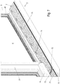
- FIG. 1 is designated by the reference numeral 1, a building sliding door.
- the building sliding door 1 here has a frame, in which fixed field 4 is accommodated in a fixed field frame 41 surrounding it and a sliding sash 3 with a glass pane accommodated in a sash frame 31.
- a threshold 2 extends perpendicular to the window frame 5, which can be recessed in a floor of the building.
- the threshold 2 essentially consists of a preferably approximately U-shaped threshold profile 21, designed to be transverse to its longitudinal axis as a cavity that is open to one side, for receiving a fitting 8 fastened to the sliding door 1, shown for example in FIG Figure 5 , and a cover 7 which can be detachably fixed to the threshold profile 21 and with which the threshold profile 21 can be closed.
- the fitting 8 is preferably firmly attached to an outside of the sash frame 31 facing the sill 2 and has a fitting neck 81 which extends vertically downward from a guide housing 6 on the sash frame 31 into the interior or cavity of the sill profile 21.
- a fitting neck 81 which extends vertically downward from a guide housing 6 on the sash frame 31 into the interior or cavity of the sill profile 21.
- an underfloor carriage 82 which can be moved along a guide rail 231 which projects from a floor 23 or is formed thereon and projects into the cavity of the sleeper profile 21.
- the fitting 8 is preferably designed as a parallel-slide-tilt-fitting for a parallel-slide-tilt-door.
- the cover 7 has, as in the Figures 2 to 4 is shown, several cover elements 71 arranged next to one another in the direction x of the longitudinal axis of the threshold profile 21.
- first and second end caps 72, 73 are arranged on mutually facing end faces 715, 716 adjacent cover elements 71. These adjacent end caps 72, 73 are separated from one another in the assembled state by a second gap 11, in which the fitting neck 81 of the fitting can be moved.
- the cover elements 71 and the end caps 72, 73 are, for example in FIG Figure 3 shown, preferably of triangular shape or trapezoidal shape with two parallel side flanks, a tread 711 facing the sash frame 31 and a support surface 712 connecting the two side surfaces 713, 714 at an angle to the tread surface 711.
- the side flank close to the sash frame 31 is configured somewhat wider than the side flank remote from the sash frame 31 serves to fix the cover 7 on a second side wall 24 of the threshold profile 21.
- the cover elements 71 and the first end cap 72 and the second end cap 73 are hung on a clamping web 242 of the second side wall 24.
- a support web 241 extending in the direction of the first side wall 24 and a clamping web 242 formed as an angle piece and together with a free end 244 of the second side wall 24 are formed on the second side wall 24 of the threshold profile 21.
- clamping web 718 which extends angularly downward from the tread surface 711 of the cover 7, while the support surfaces 712, 722, 732 of the cover 7 rest on the support web 241.
- the free end of the support surface 712, 722, 732 presses against the second side wall 24 in the assembled state and thus ensures a stable mounting of the cover elements 71 and the end caps 72, 73 on the second side wall 24 of the threshold profile 21.
- grooves 713 are formed on the narrow end faces of the cover elements 71, in which sealing elements 9 for at least partially sealing a first gap between an outer edge of the cover 7 and a first side wall 22 extending in the direction x of the longitudinal axis of the threshold profile 21 of the threshold profile 21 are included.
- the second gap 11 between the mutually facing end faces 725, 736 of the end caps 72, 73 opens into the first gap 13 between the outer edge of the cover 7, which extends in the direction x of the longitudinal axis of the threshold profile 21, and the first side wall 22 of the threshold profile 21.
- Such sealing elements 9 for at least partially sealing the second gap 11 are also arranged on the mutually facing end faces 725, 736 of the end caps 72, 73.
- the sealing elements 9 are also accommodated on the end caps 72, 73 in t-shaped grooves provided therefor.
- the sealing elements 9 are preferably designed as brush seals, the brushes 92 being held together on a sealing foot 91.
- the sealing foot has a cross-sectional contour corresponding to the groove 713.
- the cover elements 71 are preferably formed in one piece.
- the first end cap 72 and the second end cap 73 are preferably composed of several parts, at least in two parts, from an upper part 721, 731 and a lower part 722, 732.
- the end caps 72, 73 can preferably be plugged onto the end faces 715, 716 of the cover elements 71.
- receiving grooves 717 are formed on the end faces 715, 716 of the cover elements 71, preferably in the corner regions of the cover elements 71 designed as a hollow profile, into which plug elements 724, 734 formed on the end faces of the end caps can be inserted.
- plug elements 737 and corresponding receiving openings are preferably also provided in order to easily plug a respective upper part 721, 731 with a respective lower part 722, 732 can.
- the contours of the end faces of the end caps 72, 73 which are facing one another are adapted in their contours to the travel path of the fitting neck 81 of the fitting 8, depicting the running-in curve of the fitting.
- the end face 725 of the first end cap 72 facing the second end cap 73 is convex and the end face 736 of the second end cap 73 facing the first end cap 72 is concave.
- a clamping element 10 as is shown in FIGS Figures 5 and 6 is shown. With this clamping element 10, the clamping web 718 can be clamped in the groove 27 in the suspended state and thus prevents the clamping web 718 from slipping out of the groove 27 of the threshold profile 21.
- the clamping element 10 is preferably designed as a piping seal.
- This clamping element 10 essentially consists of a base body 101 and a spring arm 102 protruding at an angle from the base body 101 in the direction of the cover 7 or the cover element 71.
- This spring arm 102 is excluded in the suspended state of the cover 7 in a groove 7181 in an outer surface of the clamping web 718 facing the second side wall 24.
- a bulge 243 or the like is formed on the surface of the clamping web 242 facing the clamping web 718, which lies in the suspended state of the cover 7 in a recess or groove 7182 of the clamping web 718 and thus additionally makes it more difficult for the clamping web 718 to slide out of the groove 181 .
- the sealing elements 9 are received in grooves 26, 713, 723, 733 on mutually facing side edges of the cover 7 and a holding piece 25 protruding from the first side wall 22 of the threshold profile 21.
- the cover elements 71 preferably have ventilation slots which preferably extend in the longitudinal direction x of the cover elements 71, which are used to air-condition the space in front of the window pane.
- a pump is preferably connected laterally in the threshold profile 21, which blows air from the threshold profile 21 through the ventilation slots 74 upwards along the window panes and thereby enables ventilation or air conditioning.
- a dirt trough 12 is arranged in the sleeper profile 21, which covers the floor 23 and a part of the side walls 22, 24 of the sleeper profile 21 and serves to facilitate cleaning work in the sleeper body.
- the dirt tray 12 is preferably locked on the inner sides of the side walls 22, 24 and / or the bottom 23 of the threshold profile 21.
- the threshold profile 21 in one piece with the frame 5 as part of a frame profile. So is for example, it is conceivable to form the second side wall 24 of the threshold profile 21 in one piece on the frame 5 and to fix the bottom 23 and the first side wall 22 of the threshold profile 21 in one piece on the frame 5.
- a first projection 51 and on a horizontal section of the window frame 5 near the second side wall 24 of the threshold profile 21 a second projection 52 is fixed, which seals the wing frame 31 of the sliding sash 3 serve with respect to the frame in the closed position of the sliding sash 3.
- These projections do not project any further than the above-mentioned legal dimension above the tread surface 711 of the cover 7 of the threshold 2.
Landscapes
- Engineering & Computer Science (AREA)
- Mechanical Engineering (AREA)
- Civil Engineering (AREA)
- Structural Engineering (AREA)
- Specific Sealing Or Ventilating Devices For Doors And Windows (AREA)
Claims (14)
- Seuil (2) pour une porte coulissante de bâtiment (1), comprenant- un profilé de seuil (21) avec un rail de guidage (231) destiné à guider une ferrure (8) fixée à la porte coulissante,- une couverture (7) pouvant être fixée de façon amovible sur le profilé de seuil (21),- le profilé de seuil (21) étant conformé perpendiculairement à son axe longitudinal comme un compartiment creux ouvert sur un côté,- le rail de guidage (231) étant disposé dans le compartiment creux du profilé de seuil (21) couvert par la couverture (7),- la couverture (7) présentant au moins un élément de couverture (71) disposé dans la direction (x) de l'axe longitudinal du profilé de seuil (21), un premier interstice (13), dans lequel une partie de la ferrure (8) peut circuler, étant formé entre le profilé de seuil (21) et l'au moins un élément de couverture (71),- la ferrure (8) présentant un col de ferrure (81) qui s'étend vers le bas dans l'espace intérieur ou l'espace creux du profilé de seuil (21),caractérisé en ce que- la couverture (7) présente plusieurs éléments de couverture (71) disposés les uns à côté des autres dans la direction (x) de l'axe longitudinal du profilé de seuil (21),- un premier capuchon d'extrémité et un deuxième (72, 73) étant montés sur des faces d'extrémité (715, 716) tournées l'une vers l'autre d'éléments de couverture (71) voisins et étant séparés à distance l'un de l'autre, dans l'état monté, par un deuxième interstice (11) dans lequel le col de ferrure (81) de la ferrure (8) peut circuler.
- Seuil (2) selon la revendication 1, caractérisé en ce que des éléments d'étanchéité (9) sont disposés sur des faces d'extrémité (725, 736) tournées l'une vers l'autre des capuchons d'extrémité (72, 73) pour rendre au moins partiellement étanche le deuxième interstice (11).
- Seuil (2) selon la revendication 1 ou 2, caractérisé en ce que le deuxième interstice (11) débouche dans le premier interstice (13) entre les faces d'extrémité (725, 736) tournées l'une vers l'autre des capuchons d'extrémité (72, 73), entre un bord extérieur de la couverture (7) qui s'étend dans la direction (x) de l'axe longitudinal du profilé de seuil (21) et une première paroi latérale (22) du profilé de seuil (21).
- Seuil (2) selon l'une des revendications précédentes, caractérisé en ce que sont disposés sur des bords latéraux tournés l'un vers l'autre de la couverture (7) et sur une pièce de maintien (25) qui dépasse de la première paroi latérale (22) du profilé de seuils (21) des éléments d'étanchéités (9) destinés à rendre au moins partiellement étanche le premier interstice (13).
- Seuil (2) selon l'une des revendications précédentes, caractérisé en ce que la couverture (7) peut être accrochée sur une deuxième paroi latérale (24) du profilé de seuils (21) qui s'étend dans la direction (x) de l'axe longitudinal du profilé de seuil (21).
- Seuil (2) selon la revendication 5, caractérisé en ce que sont formées sur la deuxième paroi latérale (24) du profilé de seuil (21) une barrette d'appui (241) qui s'étend dans la direction de la première paroi latérale (24) et une barrette de serrage (242) conformée comme une équerre et qui forme une gorge (27) avec une extrémité libre (244) de la deuxième paroi latérale (24), une barrette de serrage (718) qui s'étend vers le bas à partir d'une surface de marche (711) de la couverture (7) en formant un angle reposant dans la gorge (27) dans l'état accroché et une surface d'appui (712) de la couverture reposant sur la barrette d'appui (241).
- Seuil (2) selon la revendication 6, caractérisé en ce qu'un élément de serrage (10) avec lequel la barrette de serrage (718) peut être serrée dans la gorge (27) dans l'état accroché peut être inséré dans la gorge (27).
- Seuil (2) selon les revendications 2 et 4 et, facultativement, l'une des revendications 3 ou 5 à 7 en complément, caractérisé en ce que les éléments d'étanchéité (9) sont logés dans des gorges de réception (26, 713, 723, 733) sur des bords latéraux tournés l'un vers l'autre de la couverture (7) et une partie de maintien (25) qui dépasse de la première paroi latérale (22) du profilé de seuil (21).
- Seuil (2) selon les revendications 2 et 4 et, facultativement, l'une des revendications 3 ou 5 à 8 en complément, caractérisé en ce que les éléments d'étanchéité (9) sont conformés comme un joint à brosse.
- Seuil (2) selon l'une des revendications précédentes, caractérisé en ce que la face d'extrémité (725) du premier capuchon d'extrémité (72) tournée vers le deuxième capuchon d'extrémité (73) a une forme convexe et la face d'extrémité (736) du deuxième capuchon d'extrémité (73) tournée vers le premier capuchon d'extrémité (72) a une forme concave.
- Seuil (2) selon l'une des revendications précédentes, caractérisé en ce que les capuchons d'extrémité (72, 73) peuvent être emboîtés sur les éléments de couverture (71).
- Seuil (2) selon l'une des revendications précédentes, caractérisé en ce qu'une auge recueillant les salissures (12) amovible est disposée dans le profilé de seuil (21).
- Seuil (2) selon l'une des revendications précédentes, caractérisé en ce qu'il est conformé comme le seuil d'une porte-fenêtre à souffle coulissant parallèle.
- Profilé de cadre pour une porte coulissante de bâtiment (1), avec un cadre dormant (5) et un seuil (2), caractérisé en ce que le seuil (2) est conformé selon l'une des revendications précédentes, une partie au moins du profilé de seuil (21) étant conformée d'un seul tenant avec le cadre dormant (5).
Applications Claiming Priority (1)
| Application Number | Priority Date | Filing Date | Title |
|---|---|---|---|
| DE102015100586.7A DE102015100586A1 (de) | 2015-01-15 | 2015-01-15 | Schwelle für eine Gebäudeschiebetür und Rahmenprofil |
Publications (2)
| Publication Number | Publication Date |
|---|---|
| EP3045647A1 EP3045647A1 (fr) | 2016-07-20 |
| EP3045647B1 true EP3045647B1 (fr) | 2020-07-08 |
Family
ID=54936944
Family Applications (1)
| Application Number | Title | Priority Date | Filing Date |
|---|---|---|---|
| EP15202404.8A Active EP3045647B1 (fr) | 2015-01-15 | 2015-12-23 | Seuil pour porte coulissante de batiment et profile de cadre |
Country Status (2)
| Country | Link |
|---|---|
| EP (1) | EP3045647B1 (fr) |
| DE (1) | DE102015100586A1 (fr) |
Families Citing this family (1)
| Publication number | Priority date | Publication date | Assignee | Title |
|---|---|---|---|---|
| JP6802124B2 (ja) * | 2017-08-10 | 2020-12-16 | 三協立山株式会社 | サッシ |
Family Cites Families (6)
| Publication number | Priority date | Publication date | Assignee | Title |
|---|---|---|---|---|
| DE2514292C2 (de) * | 1975-04-02 | 1985-02-28 | H. Jos. Trimborn Söhne Inh. Gottlieb Müller, 5300 Bonn | Abdeckung für eine Bodenrinne |
| DE19920534C1 (de) * | 1999-05-05 | 2000-08-31 | Alu Kaupp Gmbh | Profilschiene für die Bautechnik |
| DE202008004204U1 (de) | 2008-03-26 | 2008-07-03 | Gretsch-Unitas GmbH Baubeschläge | Schwelle für Gebäudetüren sowie Zusatzprofil zur Verwendung bei einer Schwelle bzw. einem Schwellenprofil für Gebäudetüren |
| DE202009014785U1 (de) * | 2009-11-02 | 2010-12-30 | Blösch, Dieter | Schiebetür |
| DE102011053804B4 (de) * | 2011-09-20 | 2015-02-19 | Hautau Gmbh | Wasserdichte Laufschiene für einen Schiebeflügel (Verfahren und Vorrichtung) |
| DE202014100685U1 (de) * | 2014-02-17 | 2015-05-20 | Raico Bautechnik Gmbh | Schiebefenster oder Schiebetür |
-
2015
- 2015-01-15 DE DE102015100586.7A patent/DE102015100586A1/de not_active Withdrawn
- 2015-12-23 EP EP15202404.8A patent/EP3045647B1/fr active Active
Non-Patent Citations (1)
| Title |
|---|
| None * |
Also Published As
| Publication number | Publication date |
|---|---|
| EP3045647A1 (fr) | 2016-07-20 |
| DE102015100586A1 (de) | 2016-07-21 |
Similar Documents
| Publication | Publication Date | Title |
|---|---|---|
| EP3508680B1 (fr) | Dispositif d'étanchéité et porte sectionnelle équipée d'un tel dispositif d'étanchéité | |
| EP0389000A1 (fr) | Cloison pour douche | |
| DE19962074A1 (de) | Gehäuse, insbesondere für Antriebe von automatisch und horizontal verfahrbaren Elementen | |
| DE102019135411A1 (de) | Beschlag für eine Schiebetür | |
| EP3045647B1 (fr) | Seuil pour porte coulissante de batiment et profile de cadre | |
| EP2357307A2 (fr) | Porte sectionnelle | |
| EP1091081B1 (fr) | Dispositif de guidage pour un volet roulant, un store enroulable ou similaire | |
| DE29803088U1 (de) | An einer Beschlagnut befestigbare Stulpschiene, insbesondere zum Überdecken einer mindestens einteiligen Treibstange eines Fensters, einer Tür o.dgl. | |
| DE10160802A1 (de) | Automatische Schiebetüranlage mit Seitenprofil | |
| AT512327A1 (de) | Hebe/schiebetür | |
| DE29600334U1 (de) | Magnetische Türdichtung und Zusatzprofile zu deren Herstellung | |
| EP3792444B1 (fr) | Profil de fixation pour un joint inférieur d'une lamelle de vantail de porte, lamelle inférieure pour vantail de porte et porte équipée d'une telle lamelle | |
| DE102017005236A1 (de) | Fahrzeugtür mit höhenverstellbarer Fensterscheibe | |
| EP2907952B1 (fr) | Fenêtre coulissante ou porte coulissante | |
| DE202007019187U1 (de) | Sektionaltor | |
| EP3282079B1 (fr) | Unité de joint de bas de porte pour une porte sans seuil | |
| EP0477578B1 (fr) | Cloison | |
| EP0953709A2 (fr) | Seuil de porte et profil de socle pour la combinaison avec le seuil | |
| EP3674509B1 (fr) | Élément de fermeture | |
| EP1072751A2 (fr) | Porte avec un joint d'étanchéité de sol | |
| DE102009021726A1 (de) | Vorrichtung und Anordnung eines Flächenvorhangs an einer Laufschiene | |
| DE102005003483A1 (de) | Vorrichtung zum Beschatten einer Wandöffnung, insbesondere für ein Fenster oder eine Tür | |
| DE202008006398U1 (de) | Rahmenprofil für ein Fenster oder eine Tür und Fenster- oder Türrahmen | |
| DE29618677U1 (de) | Schiebebeschlag für Türen, Fenster o.dgl. | |
| EP1277910A1 (fr) | Joint descendant pour une porte sans seuil |
Legal Events
| Date | Code | Title | Description |
|---|---|---|---|
| PUAI | Public reference made under article 153(3) epc to a published international application that has entered the european phase |
Free format text: ORIGINAL CODE: 0009012 |
|
| AK | Designated contracting states |
Kind code of ref document: A1 Designated state(s): AL AT BE BG CH CY CZ DE DK EE ES FI FR GB GR HR HU IE IS IT LI LT LU LV MC MK MT NL NO PL PT RO RS SE SI SK SM TR |
|
| AX | Request for extension of the european patent |
Extension state: BA ME |
|
| STAA | Information on the status of an ep patent application or granted ep patent |
Free format text: STATUS: REQUEST FOR EXAMINATION WAS MADE |
|
| 17P | Request for examination filed |
Effective date: 20170119 |
|
| RBV | Designated contracting states (corrected) |
Designated state(s): AL AT BE BG CH CY CZ DE DK EE ES FI FR GB GR HR HU IE IS IT LI LT LU LV MC MK MT NL NO PL PT RO RS SE SI SK SM TR |
|
| STAA | Information on the status of an ep patent application or granted ep patent |
Free format text: STATUS: EXAMINATION IS IN PROGRESS |
|
| 17Q | First examination report despatched |
Effective date: 20190822 |
|
| GRAP | Despatch of communication of intention to grant a patent |
Free format text: ORIGINAL CODE: EPIDOSNIGR1 |
|
| STAA | Information on the status of an ep patent application or granted ep patent |
Free format text: STATUS: GRANT OF PATENT IS INTENDED |
|
| INTG | Intention to grant announced |
Effective date: 20200203 |
|
| GRAS | Grant fee paid |
Free format text: ORIGINAL CODE: EPIDOSNIGR3 |
|
| GRAA | (expected) grant |
Free format text: ORIGINAL CODE: 0009210 |
|
| STAA | Information on the status of an ep patent application or granted ep patent |
Free format text: STATUS: THE PATENT HAS BEEN GRANTED |
|
| AK | Designated contracting states |
Kind code of ref document: B1 Designated state(s): AL AT BE BG CH CY CZ DE DK EE ES FI FR GB GR HR HU IE IS IT LI LT LU LV MC MK MT NL NO PL PT RO RS SE SI SK SM TR |
|
| REG | Reference to a national code |
Ref country code: AT Ref legal event code: REF Ref document number: 1288623 Country of ref document: AT Kind code of ref document: T Effective date: 20200715 Ref country code: CH Ref legal event code: EP |
|
| REG | Reference to a national code |
Ref country code: DE Ref legal event code: R096 Ref document number: 502015012950 Country of ref document: DE |
|
| REG | Reference to a national code |
Ref country code: IE Ref legal event code: FG4D Free format text: LANGUAGE OF EP DOCUMENT: GERMAN |
|
| REG | Reference to a national code |
Ref country code: LT Ref legal event code: MG4D |
|
| REG | Reference to a national code |
Ref country code: NL Ref legal event code: MP Effective date: 20200708 |
|
| PG25 | Lapsed in a contracting state [announced via postgrant information from national office to epo] |
Ref country code: ES Free format text: LAPSE BECAUSE OF FAILURE TO SUBMIT A TRANSLATION OF THE DESCRIPTION OR TO PAY THE FEE WITHIN THE PRESCRIBED TIME-LIMIT Effective date: 20200708 Ref country code: GR Free format text: LAPSE BECAUSE OF FAILURE TO SUBMIT A TRANSLATION OF THE DESCRIPTION OR TO PAY THE FEE WITHIN THE PRESCRIBED TIME-LIMIT Effective date: 20201009 Ref country code: LT Free format text: LAPSE BECAUSE OF FAILURE TO SUBMIT A TRANSLATION OF THE DESCRIPTION OR TO PAY THE FEE WITHIN THE PRESCRIBED TIME-LIMIT Effective date: 20200708 Ref country code: NO Free format text: LAPSE BECAUSE OF FAILURE TO SUBMIT A TRANSLATION OF THE DESCRIPTION OR TO PAY THE FEE WITHIN THE PRESCRIBED TIME-LIMIT Effective date: 20201008 Ref country code: PT Free format text: LAPSE BECAUSE OF FAILURE TO SUBMIT A TRANSLATION OF THE DESCRIPTION OR TO PAY THE FEE WITHIN THE PRESCRIBED TIME-LIMIT Effective date: 20201109 Ref country code: SE Free format text: LAPSE BECAUSE OF FAILURE TO SUBMIT A TRANSLATION OF THE DESCRIPTION OR TO PAY THE FEE WITHIN THE PRESCRIBED TIME-LIMIT Effective date: 20200708 Ref country code: BG Free format text: LAPSE BECAUSE OF FAILURE TO SUBMIT A TRANSLATION OF THE DESCRIPTION OR TO PAY THE FEE WITHIN THE PRESCRIBED TIME-LIMIT Effective date: 20201008 Ref country code: HR Free format text: LAPSE BECAUSE OF FAILURE TO SUBMIT A TRANSLATION OF THE DESCRIPTION OR TO PAY THE FEE WITHIN THE PRESCRIBED TIME-LIMIT Effective date: 20200708 Ref country code: FI Free format text: LAPSE BECAUSE OF FAILURE TO SUBMIT A TRANSLATION OF THE DESCRIPTION OR TO PAY THE FEE WITHIN THE PRESCRIBED TIME-LIMIT Effective date: 20200708 |
|
| PG25 | Lapsed in a contracting state [announced via postgrant information from national office to epo] |
Ref country code: IS Free format text: LAPSE BECAUSE OF FAILURE TO SUBMIT A TRANSLATION OF THE DESCRIPTION OR TO PAY THE FEE WITHIN THE PRESCRIBED TIME-LIMIT Effective date: 20201108 Ref country code: PL Free format text: LAPSE BECAUSE OF FAILURE TO SUBMIT A TRANSLATION OF THE DESCRIPTION OR TO PAY THE FEE WITHIN THE PRESCRIBED TIME-LIMIT Effective date: 20200708 Ref country code: RS Free format text: LAPSE BECAUSE OF FAILURE TO SUBMIT A TRANSLATION OF THE DESCRIPTION OR TO PAY THE FEE WITHIN THE PRESCRIBED TIME-LIMIT Effective date: 20200708 Ref country code: LV Free format text: LAPSE BECAUSE OF FAILURE TO SUBMIT A TRANSLATION OF THE DESCRIPTION OR TO PAY THE FEE WITHIN THE PRESCRIBED TIME-LIMIT Effective date: 20200708 |
|
| PG25 | Lapsed in a contracting state [announced via postgrant information from national office to epo] |
Ref country code: NL Free format text: LAPSE BECAUSE OF FAILURE TO SUBMIT A TRANSLATION OF THE DESCRIPTION OR TO PAY THE FEE WITHIN THE PRESCRIBED TIME-LIMIT Effective date: 20200708 |
|
| REG | Reference to a national code |
Ref country code: DE Ref legal event code: R097 Ref document number: 502015012950 Country of ref document: DE |
|
| PG25 | Lapsed in a contracting state [announced via postgrant information from national office to epo] |
Ref country code: SM Free format text: LAPSE BECAUSE OF FAILURE TO SUBMIT A TRANSLATION OF THE DESCRIPTION OR TO PAY THE FEE WITHIN THE PRESCRIBED TIME-LIMIT Effective date: 20200708 Ref country code: RO Free format text: LAPSE BECAUSE OF FAILURE TO SUBMIT A TRANSLATION OF THE DESCRIPTION OR TO PAY THE FEE WITHIN THE PRESCRIBED TIME-LIMIT Effective date: 20200708 Ref country code: EE Free format text: LAPSE BECAUSE OF FAILURE TO SUBMIT A TRANSLATION OF THE DESCRIPTION OR TO PAY THE FEE WITHIN THE PRESCRIBED TIME-LIMIT Effective date: 20200708 Ref country code: IT Free format text: LAPSE BECAUSE OF FAILURE TO SUBMIT A TRANSLATION OF THE DESCRIPTION OR TO PAY THE FEE WITHIN THE PRESCRIBED TIME-LIMIT Effective date: 20200708 Ref country code: DK Free format text: LAPSE BECAUSE OF FAILURE TO SUBMIT A TRANSLATION OF THE DESCRIPTION OR TO PAY THE FEE WITHIN THE PRESCRIBED TIME-LIMIT Effective date: 20200708 Ref country code: CZ Free format text: LAPSE BECAUSE OF FAILURE TO SUBMIT A TRANSLATION OF THE DESCRIPTION OR TO PAY THE FEE WITHIN THE PRESCRIBED TIME-LIMIT Effective date: 20200708 |
|
| PLBE | No opposition filed within time limit |
Free format text: ORIGINAL CODE: 0009261 |
|
| STAA | Information on the status of an ep patent application or granted ep patent |
Free format text: STATUS: NO OPPOSITION FILED WITHIN TIME LIMIT |
|
| PG25 | Lapsed in a contracting state [announced via postgrant information from national office to epo] |
Ref country code: AL Free format text: LAPSE BECAUSE OF FAILURE TO SUBMIT A TRANSLATION OF THE DESCRIPTION OR TO PAY THE FEE WITHIN THE PRESCRIBED TIME-LIMIT Effective date: 20200708 |
|
| 26N | No opposition filed |
Effective date: 20210409 |
|
| PG25 | Lapsed in a contracting state [announced via postgrant information from national office to epo] |
Ref country code: SK Free format text: LAPSE BECAUSE OF FAILURE TO SUBMIT A TRANSLATION OF THE DESCRIPTION OR TO PAY THE FEE WITHIN THE PRESCRIBED TIME-LIMIT Effective date: 20200708 |
|
| REG | Reference to a national code |
Ref country code: CH Ref legal event code: PL |
|
| GBPC | Gb: european patent ceased through non-payment of renewal fee |
Effective date: 20201223 |
|
| PG25 | Lapsed in a contracting state [announced via postgrant information from national office to epo] |
Ref country code: SI Free format text: LAPSE BECAUSE OF FAILURE TO SUBMIT A TRANSLATION OF THE DESCRIPTION OR TO PAY THE FEE WITHIN THE PRESCRIBED TIME-LIMIT Effective date: 20200708 Ref country code: MC Free format text: LAPSE BECAUSE OF FAILURE TO SUBMIT A TRANSLATION OF THE DESCRIPTION OR TO PAY THE FEE WITHIN THE PRESCRIBED TIME-LIMIT Effective date: 20200708 |
|
| REG | Reference to a national code |
Ref country code: BE Ref legal event code: MM Effective date: 20201231 |
|
| PG25 | Lapsed in a contracting state [announced via postgrant information from national office to epo] |
Ref country code: FR Free format text: LAPSE BECAUSE OF NON-PAYMENT OF DUE FEES Effective date: 20201231 Ref country code: LU Free format text: LAPSE BECAUSE OF NON-PAYMENT OF DUE FEES Effective date: 20201223 Ref country code: IE Free format text: LAPSE BECAUSE OF NON-PAYMENT OF DUE FEES Effective date: 20201223 |
|
| PG25 | Lapsed in a contracting state [announced via postgrant information from national office to epo] |
Ref country code: CH Free format text: LAPSE BECAUSE OF NON-PAYMENT OF DUE FEES Effective date: 20201231 Ref country code: GB Free format text: LAPSE BECAUSE OF NON-PAYMENT OF DUE FEES Effective date: 20201223 Ref country code: LI Free format text: LAPSE BECAUSE OF NON-PAYMENT OF DUE FEES Effective date: 20201231 |
|
| REG | Reference to a national code |
Ref country code: AT Ref legal event code: MM01 Ref document number: 1288623 Country of ref document: AT Kind code of ref document: T Effective date: 20201223 |
|
| PG25 | Lapsed in a contracting state [announced via postgrant information from national office to epo] |
Ref country code: AT Free format text: LAPSE BECAUSE OF NON-PAYMENT OF DUE FEES Effective date: 20201223 |
|
| PG25 | Lapsed in a contracting state [announced via postgrant information from national office to epo] |
Ref country code: IS Free format text: LAPSE BECAUSE OF FAILURE TO SUBMIT A TRANSLATION OF THE DESCRIPTION OR TO PAY THE FEE WITHIN THE PRESCRIBED TIME-LIMIT Effective date: 20201108 Ref country code: TR Free format text: LAPSE BECAUSE OF FAILURE TO SUBMIT A TRANSLATION OF THE DESCRIPTION OR TO PAY THE FEE WITHIN THE PRESCRIBED TIME-LIMIT Effective date: 20200708 Ref country code: MT Free format text: LAPSE BECAUSE OF FAILURE TO SUBMIT A TRANSLATION OF THE DESCRIPTION OR TO PAY THE FEE WITHIN THE PRESCRIBED TIME-LIMIT Effective date: 20200708 Ref country code: CY Free format text: LAPSE BECAUSE OF FAILURE TO SUBMIT A TRANSLATION OF THE DESCRIPTION OR TO PAY THE FEE WITHIN THE PRESCRIBED TIME-LIMIT Effective date: 20200708 |
|
| PG25 | Lapsed in a contracting state [announced via postgrant information from national office to epo] |
Ref country code: MK Free format text: LAPSE BECAUSE OF FAILURE TO SUBMIT A TRANSLATION OF THE DESCRIPTION OR TO PAY THE FEE WITHIN THE PRESCRIBED TIME-LIMIT Effective date: 20200708 |
|
| PG25 | Lapsed in a contracting state [announced via postgrant information from national office to epo] |
Ref country code: BE Free format text: LAPSE BECAUSE OF NON-PAYMENT OF DUE FEES Effective date: 20201231 |
|
| P01 | Opt-out of the competence of the unified patent court (upc) registered |
Effective date: 20230815 |
|
| PGFP | Annual fee paid to national office [announced via postgrant information from national office to epo] |
Ref country code: DE Payment date: 20241212 Year of fee payment: 10 |