EP3508445B1 - Aufzugautopositionierung für prüfende wartung - Google Patents
Aufzugautopositionierung für prüfende wartung Download PDFInfo
- Publication number
- EP3508445B1 EP3508445B1 EP19150380.4A EP19150380A EP3508445B1 EP 3508445 B1 EP3508445 B1 EP 3508445B1 EP 19150380 A EP19150380 A EP 19150380A EP 3508445 B1 EP3508445 B1 EP 3508445B1
- Authority
- EP
- European Patent Office
- Prior art keywords
- elevator
- elevator car
- elevator system
- camera
- maintenance
- Prior art date
- Legal status (The legal status is an assumption and is not a legal conclusion. Google has not performed a legal analysis and makes no representation as to the accuracy of the status listed.)
- Active
Links
- 238000012423 maintenance Methods 0.000 title claims description 63
- 238000000034 method Methods 0.000 claims description 32
- 230000002547 anomalous effect Effects 0.000 claims description 16
- 238000012545 processing Methods 0.000 description 13
- 238000012517 data analytics Methods 0.000 description 6
- 230000005856 abnormality Effects 0.000 description 4
- 230000008859 change Effects 0.000 description 4
- 238000010586 diagram Methods 0.000 description 4
- 230000008569 process Effects 0.000 description 4
- 238000007689 inspection Methods 0.000 description 3
- 229910000831 Steel Inorganic materials 0.000 description 2
- 230000002159 abnormal effect Effects 0.000 description 2
- 230000009471 action Effects 0.000 description 2
- 238000004891 communication Methods 0.000 description 2
- 230000006870 function Effects 0.000 description 2
- 230000007246 mechanism Effects 0.000 description 2
- 238000012986 modification Methods 0.000 description 2
- 230000004048 modification Effects 0.000 description 2
- 230000002093 peripheral effect Effects 0.000 description 2
- 239000010959 steel Substances 0.000 description 2
- 230000001133 acceleration Effects 0.000 description 1
- SAZUGELZHZOXHB-UHFFFAOYSA-N acecarbromal Chemical compound CCC(Br)(CC)C(=O)NC(=O)NC(C)=O SAZUGELZHZOXHB-UHFFFAOYSA-N 0.000 description 1
- 230000004075 alteration Effects 0.000 description 1
- 230000015556 catabolic process Effects 0.000 description 1
- 238000006731 degradation reaction Methods 0.000 description 1
- 230000002542 deteriorative effect Effects 0.000 description 1
- 238000005516 engineering process Methods 0.000 description 1
- 239000000463 material Substances 0.000 description 1
- 238000005259 measurement Methods 0.000 description 1
- 238000012544 monitoring process Methods 0.000 description 1
- 238000012552 review Methods 0.000 description 1
- 239000004984 smart glass Substances 0.000 description 1
- 239000013589 supplement Substances 0.000 description 1
- 238000012360 testing method Methods 0.000 description 1
- 238000012795 verification Methods 0.000 description 1
Images
Classifications
-
- B—PERFORMING OPERATIONS; TRANSPORTING
- B66—HOISTING; LIFTING; HAULING
- B66B—ELEVATORS; ESCALATORS OR MOVING WALKWAYS
- B66B5/00—Applications of checking, fault-correcting, or safety devices in elevators
- B66B5/0006—Monitoring devices or performance analysers
- B66B5/0018—Devices monitoring the operating condition of the elevator system
- B66B5/0025—Devices monitoring the operating condition of the elevator system for maintenance or repair
-
- B—PERFORMING OPERATIONS; TRANSPORTING
- B66—HOISTING; LIFTING; HAULING
- B66B—ELEVATORS; ESCALATORS OR MOVING WALKWAYS
- B66B1/00—Control systems of elevators in general
- B66B1/02—Control systems without regulation, i.e. without retroactive action
- B66B1/06—Control systems without regulation, i.e. without retroactive action electric
-
- B—PERFORMING OPERATIONS; TRANSPORTING
- B66—HOISTING; LIFTING; HAULING
- B66B—ELEVATORS; ESCALATORS OR MOVING WALKWAYS
- B66B1/00—Control systems of elevators in general
- B66B1/34—Details, e.g. call counting devices, data transmission from car to control system, devices giving information to the control system
- B66B1/3415—Control system configuration and the data transmission or communication within the control system
- B66B1/3423—Control system configuration, i.e. lay-out
- B66B1/343—Fault-tolerant or redundant control system configuration
-
- B—PERFORMING OPERATIONS; TRANSPORTING
- B66—HOISTING; LIFTING; HAULING
- B66B—ELEVATORS; ESCALATORS OR MOVING WALKWAYS
- B66B5/00—Applications of checking, fault-correcting, or safety devices in elevators
- B66B5/0006—Monitoring devices or performance analysers
- B66B5/0018—Devices monitoring the operating condition of the elevator system
- B66B5/0031—Devices monitoring the operating condition of the elevator system for safety reasons
-
- B—PERFORMING OPERATIONS; TRANSPORTING
- B66—HOISTING; LIFTING; HAULING
- B66B—ELEVATORS; ESCALATORS OR MOVING WALKWAYS
- B66B5/00—Applications of checking, fault-correcting, or safety devices in elevators
- B66B5/0043—Devices enhancing safety during maintenance
- B66B5/005—Safety of maintenance personnel
-
- B—PERFORMING OPERATIONS; TRANSPORTING
- B66—HOISTING; LIFTING; HAULING
- B66B—ELEVATORS; ESCALATORS OR MOVING WALKWAYS
- B66B5/00—Applications of checking, fault-correcting, or safety devices in elevators
- B66B5/0087—Devices facilitating maintenance, repair or inspection tasks
-
- B—PERFORMING OPERATIONS; TRANSPORTING
- B66—HOISTING; LIFTING; HAULING
- B66B—ELEVATORS; ESCALATORS OR MOVING WALKWAYS
- B66B1/00—Control systems of elevators in general
- B66B1/34—Details, e.g. call counting devices, data transmission from car to control system, devices giving information to the control system
- B66B1/3415—Control system configuration and the data transmission or communication within the control system
- B66B1/3423—Control system configuration, i.e. lay-out
Definitions
- the subject matter disclosed herein generally relates to elevator systems and, more particularly, to elevator auto-positioning for performing maintenance.
- US 2011/0067958 A1 describes an elevator system (100) that includes various sensors that are used in a method of maintenance.
- WO 03/066497 describes a method for telemonitoring the condition of an elevator and determining its need for maintenance by performing an automatic test run of the elevator car to collect data.
- WO 2006/048497 describes an elevator system that includes monitoring cameras and a method for executing elevator control actions.
- an elevator system is provided as claimed in claim 1.
- controller is further configured to transmit, by a transceiver, the one or more images or video captured from the camera.
- Further embodiments of the elevator system may include one or more sensors associated with the elevator system and wherein the controller is further configured to transmit sensor data, by the transceiver, to a maintenance server, wherein the maintenance server determines the maintenance request based at least part on the sensor data.
- Further embodiments of the elevator system may include that the maintenance server analyzes the sensor data to determine anomalous sensor data, the maintenance server determines a root cause of the anomalous sensor data based at least in part on a root cause analysis of the anomalous sensor data, and the maintenance request comprises the root cause.
- Further embodiments of the elevator system may include that the analyzing the maintenance request to determine an operational mode for the elevator car includes analyzing the root cause to identify one or more components in the elevator system associated with the root cause. A location of the one or more components in the elevator system is determined and at least one camera position, one elevator car location, and a velocity of the elevator car are determined for the operational mode.
- Further embodiments of the elevator system may include that the one or more images or video captured from the camera is transmitted to a user device.
- controller is further configured to receive camera adjustment data from a user.
- Further embodiments of the elevator system may include that the one or more images or video captured from the camera is transmitted to a maintenance server.
- Further embodiments of the elevator system may include that the maintenance server analyzes the one or more images or video to determine the maintenance request based at least in part on the analysis of the images or video.
- a method is provided as claimed in claim 10Further embodiments of the method may include transmitting, by a transceiver, the one or more images or video captured from the camera.
- Further embodiments of the method may include that obtaining sensor data from one or more sensors associated with the elevator system and transmitting the sensor data, by the transceiver, to a maintenance server, wherein the maintenance server determines the maintenance request based at least part on the sensor data.
- Further embodiments of the method may include that the maintenance server analyzes the sensor data to determine anomalous sensor data, the maintenance server determines a root cause of the anomalous sensor data based at least in part on a root cause analysis of the anomalous sensor data, and the maintenance request comprises the root cause.
- Further embodiments of the method may include that the analyzing the maintenance request to determine an operational mode for the elevator car includes analyzing the root cause to identify one or more components in the elevator system associated with the root cause. A location of the one or more components in the elevator system is determined and at least one camera position, one elevator car location, and a velocity of the elevator car are determined for the operational mode.
- Further embodiments of the method may include that the one or more images or video captured from the camera is transmitted to a user device.
- Further embodiments of the method may include receiving camera adjustment data from a user.
- Further embodiments of the method may include that the one or more images or video captured from the camera is transmitted to a maintenance server.
- Further embodiments of the method may include that the maintenance server analyzes the one or more images or video to determine the maintenance request associated with the elevator system based at least in part on the analysis of the one or more images or video.
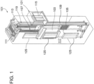
- FIG. 1 is a perspective view of an elevator system 101 including an elevator car 103, a counterweight 105, a roping 107, a guide rail 109, a machine 111, a position encoder 113, and a controller 115.
- the elevator car 103 and counterweight 105 are connected to each other by the roping 107.
- the roping 107 may include or be configured as, for example, ropes, steel cables, and/or coated-steel belts.
- the counterweight 105 is configured to balance a load of the elevator car 103 and is configured to facilitate movement of the elevator car 103 concurrently and in an opposite direction with respect to the counterweight 105 within an elevator shaft 117 and along the guide rail 109.
- the roping 107 engages the machine 111, which is part of an overhead structure of the elevator system 101.
- the machine 111 is configured to control movement between the elevator car 103 and the counterweight 105.
- the position encoder 113 may be mounted on an upper sheave of a speed-governor system 119 and may be configured to provide position signals related to a position of the elevator car 103 within the elevator shaft 117. In other embodiments, the position encoder 113 may be directly mounted to a moving component of the machine 111, or may be located in other positions and/or configurations as known in the art.
- the controller 115 is located, as shown, in a controller room 121 of the elevator shaft 117 and is configured to control the operation of the elevator system 101, and particularly the elevator car 103.
- the controller 115 may provide drive signals to the machine 111 to control the acceleration, deceleration, leveling, stopping, etc. of the elevator car 103.
- the controller 115 may also be configured to receive position signals from the position encoder 113.
- the elevator car 103 may stop at one or more landings 125 as controlled by the controller 115.
- the controller 115 can be located and/or configured in other locations or positions within the elevator system 101.
- the machine 111 may include a motor or similar driving mechanism.
- the machine 111 is configured to include an electrically driven motor.
- the power supply for the motor may be any power source, including a power grid, which, in combination with other components, is supplied to the motor.
- FIG. 1 is merely a non-limiting example presented for illustrative and explanatory purposes.
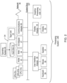
- processors 21a, 21b, 21c, etc. collectively or generically referred to as processor(s) 21.
- processors 21 may include a reduced instruction set computer (RISC) microprocessor.
- RISC reduced instruction set computer
- processors 21 are coupled to system memory 34 and various other components via a system bus 33.
- ROM Read only memory
- BIOS basic input/output system
- FIG. 2 further depicts an input/output (I/O) adapter 27 and a network adapter 26 coupled to the system bus 33.
- I/O adapter 27 may be a small computer system interface (SCSI) adapter that communicates with a hard disk 23 and/or tape storage drive 25 or any other similar component.
- I/O adapter 27, hard disk 23, and tape storage device 25 are collectively referred to herein as mass storage 24.
- Operating system 40 for execution on the processing system 200 may be stored in mass storage 24.
- a network adapter 26 interconnects bus 33 with an outside network 36 enabling data processing system 200 to communicate with other such systems.
- a screen (e.g., a display monitor) 35 is connected to system bus 33 by display adaptor 32, which may include a graphics adapter to improve the performance of graphics intensive applications and a video controller.
- adapters 27, 26, and 32 may be connected to one or more I/O busses that are connected to system bus 33 via an intermediate bus bridge (not shown).
- Suitable I/O buses for connecting peripheral devices such as hard disk controllers, network adapters, and graphics adapters typically include common protocols, such as the Peripheral Component Interconnect (PCI).
- PCI Peripheral Component Interconnect
- Additional input/output devices are shown as connected to system bus 33 via user interface adapter 28 and display adapter 32.
- a keyboard 29, mouse 30, and speaker 31 all interconnected to bus 33 via user interface adapter 28, which may include, for example, a Super I/O chip integrating multiple device adapters into a single integrated circuit.
- the processing system 200 includes a graphics processing unit 41.
- Graphics processing unit 41 is a specialized electronic circuit designed to manipulate and alter memory to accelerate the creation of images in a frame buffer intended for output to a display.
- Graphics processing unit 41 is very efficient at manipulating computer graphics and image processing and has a highly parallel structure that makes it more effective than general-purpose CPUs for algorithms where processing of large blocks of data is done in parallel.
- the processing system 200 described herein is merely exemplary and not intended to limit the application, uses, and/or technical scope of the present disclosure, which can be embodied in various forms known in the art.
- the system 200 includes processing capability in the form of processors 21, storage capability including system memory 34 and mass storage 24, input means such as keyboard 29 and mouse 30, and output capability including speaker 31 and display 35.
- processing capability in the form of processors 21, storage capability including system memory 34 and mass storage 24, input means such as keyboard 29 and mouse 30, and output capability including speaker 31 and display 35.
- a portion of system memory 34 and mass storage 24 collectively store an operating system coordinate the functions of the various components shown in FIG. 2.
- FIG. 2 is merely a non-limiting example presented for illustrative and explanatory purposes. In one or more embodiments, any embedded computing platform can be utilized.
- CBM condition based maintenance
- Root cause or prediction for some issues may be identified with a high confidence value. However, in some cases the root cause is not known or the analytics has identified a possible root cause with a low confidence value. In this case, the mechanic will be scheduled to visit the unit and be instructed to check certain components and equipment on the elevator. It is desired to have a way to automatically gather additional information to determine a root cause of the issue, or to validate or invalidate a potential root cause that has a low confidence rating from the data analytics.
- one or more embodiments address the above-described shortcomings of the prior art by providing elevator auto-positioning for validating maintenance. Aspects include utilizing an elevator controller in the elevator system to move or position an elevator car on command, a camera mounted to view specified elevator equipment, the elevator controller that can control the camera and send images or video to a cloud computing network ("cloud"), and a cloud application to store and analyze or display the images.
- the camera and elevator control may be performed by a separate controller such as a mobile device, remote server or computer.
- a local, mobile or cloud based application can send a request for an image or video of elevator equipment located at a specified position in an elevator system.
- the request can also include the direction and speed to move an elevator car within the elevator system.
- the elevator controller can move the elevator car to the position specified.
- the elevator controller can utilize one or more sensors to detect when the elevator car is in the specified position.
- the elevator controller can send a command to a camera.
- the command can include an adjustment to the position, zoom, orientation, and the like, of the camera.
- the cameras can be adjustable to pan, zoom, and focus on multiple locations and elevator components.
- the command can direct the camera to capture one or more images or video of the specified equipment.
- the elevator controller can command the elevator car to move at a specified speed (or range of speeds or varying speeds) and direction to allow for one or more cameras to capture video or multiple images.
- the controller can send the video or image data, via a transceiver or other electronic communication device, to a cloud computing server for verification of the equipment by a technician or through the use of analytics.
- the images or videos can be viewed by accessing the cloud computing server.
- a maintenance technician can access the server using a user devices such as a computer, tablet, phone, or the like.
- the images and videos can be stored local to the elevator system and accessed by a maintenance technician through a user interface local to the elevator system or accessed remotely by a user device through a network.
- the images or videos can be viewed or analyzed to validate or invalidate the maintenance issue.
- the maintenance issue can be identified by logic or data analytics algorithms such as condition based maintenance.
- the analysis of the maintenance issue can be used to identify a root cause of an unknown or anomalous sensor reading such as a sound, vibration, and/or abnormality.
- the images and/or video can be transmitted to a smart device, such as a smart phone or tablet, of an elevator mechanic or technician for review on the smart device.
- the elevator car can be moved to any position within the elevator shaft.
- the elevator car can have cameras mounted at different locations either on the elevator car or in the elevator shaft positioned to view equipment located on the elevator car or in the elevator shaft. The cameras can also be adjusted to capture multiple views of the elevator equipment.
- a camera can be mounted on an elevator car to view the rails in an elevator system and the elevator controller can move the elevator car into position to view portions of a suspected rail bracket along the elevator rail.
- the elevator controller can move the elevator car into position to view portions of a suspected rail bracket along the elevator rail.
- Another example is mounting a camera to a fixed location in the elevator system to view an elevator shaft allowing the elevator controller to move an elevator car to get a view of a specific section of elevator ropes.
- an elevator controller can cycle the elevator car to particular locations to capture images or video of components on the elevator car, such as the doors, that are identified by analytics.
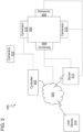
- FIG. 3 depicts a system 300 for inspecting an elevator system according to one or more embodiments.
- the system 300 includes a controller 302, an elevator car 304, one or more sensor(s) 308, one or more camera(s) 310, a server 312, and a network 320.
- the system 300 includes a user device 314.
- the elevator car 304 is part of an elevator system, such as the elevator system 101 with elevator car 103 depicted in FIG. 1 .
- the controller 302 can include more than one controller (e.g., microcontroller circuit) that can operate the elevator car 103, cameras 310, sensors 308, or any combination of components of the system 300.
- Each individual component can have a separate controller utilized to perform some or all the functionality of the component.
- an elevator controller can operate the elevator car 304, while a camera controller can operate the cameras 310.
- the controller 302 can be implemented on the processing system 200 found in FIG. 2 .
- a cloud computing system can be in wired or wireless electronic communication with one or all of the elements of the system 300. Cloud computing can supplement, support or replace some or all of the functionality of the elements of the system 300. Additionally, some or all of the functionality of the elements of system 300 can be implemented as a node of a cloud computing system.
- a cloud computing node is only one example of a suitable cloud computing node and is not intended to suggest any limitation as to the scope of use or functionality of embodiments described herein.
- the network 320 can be a cloud network.
- the controller 302 is operable to control the elevator car 304 and maneuver the elevator car 304 within an elevator shaft.
- the controller 302 is operable to control the cameras 310 and capture images and video from each of the cameras 310 located on or around the elevator car 304.
- the media (e.g., images and video) captured from the cameras 310 can be transmitted to the controller 302 and stored in the server 312.
- the media captured from the cameras 310 can be transmitted to a user device 314 via the network 320.
- the user device 314 can include a device carried by a user, such as a smart phone, PDA, tablet, smartwatch, smart glasses, laptop, etc.
- the cameras 310 can be mounted in an elevator system at locations such as, for example, the top of the elevator shaft, the bottom of the elevator shaft, the top of an elevator car 304, the bottom of the elevator car 304, a machine room, or any other location in the elevator system, including within the elevator car 304.
- the cameras 310 can be any type of camera that can be used to generate video and/or still frame images.
- the cameras 310 can capture any type of video images such as, for example, infrared images and the like.
- the cameras 310 can be wired or wireless cameras that can connect to the controller 302 through a wired or wireless network connection.
- the cameras 310 mentioned herein are only examples of suitable camera types and are not intended to suggest any limitation as to the scope of use or functionality of the cameras.
- the sensors 308 can be any type of sensor including but not limited to sensors operable to detect sound, vibrations, and/or any type of abnormality in the system 300.
- the sensor 308 can transmit an indication of the abnormality to the server 312 for analysis.
- the server 312 can utilize any type of analytics or logic to perform a root cause analysis to determine the root cause of the abnormal sensor reading.
- a root cause can be determined within a confidence level (e.g., confidence interval) and based on this confidence level, an action can be taken by the system to either validate or invalidate the root cause analysis.
- the server 312 can perform the root cause analysis to determine that there is a potential rail issue between floor 2 and floor 4 in an elevator system.
- the server 312 can transmit a signal to the controller 302 to place the elevator car 304 in a specific operational mode to attempt to validate or invalidate the potential issue.
- the operation mode includes moving the elevator car 304 from floor 2 to floor 4 at half the normal speed.
- the operational mode can include an indication of specific locations on or near the elevator car 304 for inspection as well as speed and direction of the elevator car 304.
- the cameras 310 can be adjusted to view portions of the elevator rail at or near where the anomalous reading was taken by a sensor 308.
- the controller 302 based on the operational mode, can command the elevator car 304 to move from floor 2 to floor 4 at half speed while the camera(s) 310 are adjusted to capture images and videos of specific locations.
- the captured images and videos are stored locally in the controller 302 or in the server 312 for further analysis by data analytics or by an elevator mechanic.
- the cameras can be adjusted during the operational mode by an elevator mechanic utilizing a user device 314 to zoom, pan, and focus on specific components in the elevator system.
- the cameras are operable to pan, zoom, adjust angles, and otherwise maneuver to view multiple locations on or around the elevator car 304.
- the captured images and videos can be stored locally in the controller and uploaded to a server 312 when a mechanic arrives at the elevator system 300.
- the server 312 can notify a mechanic to perform maintenance on the elevator car based on data analytics of the captured images or video. Based on the root cause analysis, the mechanic can be directed to specific locations in the elevator system for maintenance work. In one or more embodiments, the images or video can be sent directly to a user device of the elevator mechanic.
- the root cause analysis can be performed by obtaining stored images or video of elevator components for the elevator car 304 or elevator system that have been indicated as being in good operating condition by a mechanic. These images and/or video can be utilized as referenced images and compared to captured media during an operational mode for the elevator car 304 to determine if a maintenance issue is present in the elevator system.
- the reference images may be obtained while a mechanic is on site working on the elevator car 304 and has deemed that all components of the car 304 are operating within normal tolerances.
- the controller 302 can capture new images based on a request from the server to investigate anomalous sensor 308 readings. These new images can be compared against the reference images to validate or invalidate a root cause analysis.
- Validating the root cause analysis can cause the server to notify a mechanic to perform maintenance on the elevator system.
- a comparison score can be obtained based on the changes between the images. This may be performed by comparing pixel values of elevator components in the new image and the reference image, or by any other known image comparison tool. A difference in pixel value for one component in the new image and the reference image indicates a change between the new image and the reference image. The absolute values of all the pixel differences between new image and the reference image may then be summed to generate a comparison score. The pixel comparisons may be made, for example, based on change in color, change in brightness, etc.
- Comparing pixel values is merely exemplary and not intended to limit the application, uses, and/or technical scope for image or video analytics, which can be embodied utilizing various techniques.
- the pixel comparison is a non-limiting example presented for illustrative and explanatory purposes.
- any of the analytics described herein can be performed on the server 312 and/or a user device 312 including but not limited to the root cause analysis.
- the controller 302 can generate an alert and send the alert to the user device 314.
- the threshold value can be adjusted by the user. Multiple threshold values can be set to determine the type of alert sent to the user. For example, exceeding a larger threshold value may generate an alert sent more frequently or sent to multiple user devices 314 to amplify the severity of the change to the component image.
- the threshold value can be a number, percentage, range, or any other type of threshold. For example, a comparison score exceeding 75 could indicate a need for a significant alert being sent to one or more mechanics. A comparison score between the ranges of 25 to 50 can generate an alert that is of a lower priority.
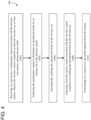
- FIG. 4 depicts a flow diagram of a method for inspecting an elevator system according to one or more embodiments.
- the method 400 includes receiving, by a processor, a maintenance request associated with the elevator system, wherein the elevator system comprises at least one elevator car, at least one camera, and an elevator shaft, as shown in block 402.
- the method 400 includes analyzing the maintenance request to determine an operational mode for an elevator car in the elevator system.
- the method 400 at block 406, includes automatically enabling the operational mode for the elevator car.
- the method 400 includes capturing, from the camera, media associated with the elevator system responsive to enabling the operational mode for the elevator car.
- the method 400 includes transmitting, by a transceiver, the media captured from the camera.
Landscapes
- Engineering & Computer Science (AREA)
- Automation & Control Theory (AREA)
- Computer Networks & Wireless Communication (AREA)
- Indicating And Signalling Devices For Elevators (AREA)
Claims (14)
- Aufzugssystem (101), umfassend:einen Aufzugsschacht (117);eine Aufzugskabine (304) und eine Aufzugssteuerung, um die Aufzugskabine auf Befehl zu bewegen oder zu positionieren; und mindestens eine Kamera (310), die montiert ist, um eine bestimmte Aufzugsausrüstung zu sehen, wobei die Kamera (310) von einer Steuerung (302) betrieben wird, dadurch gekennzeichnet, dass die Steuerung (302) konfiguriert ist zum:Empfangen einer Wartungsanforderung für ein Bild oder Video einer Aufzugsausrüstung, die sich an einer bestimmten Position in dem Aufzugssystem (101) befindet;Analysieren der Wartungsanforderung, um einen Betriebsmodus für die Aufzugskabine (304) zu bestimmen, wobei der Betriebsmodus die Richtung und Geschwindigkeit zum Bewegen der Aufzugskabine innerhalb des Aufzugssystems beinhaltet;Aktivieren des Betriebsmodus für die Aufzugskabine (304);Erfassen, von der Kamera (310), eines oder mehrerer Bilder oder Videos der bestimmten Ausrüstung als Reaktion auf das Aktivieren des Betriebsmodus für die Aufzugskabine (304).
- Aufzugssystem (101) nach Anspruch 1, wobei die Steuerung (302) ferner konfiguriert ist zum:
Übertragen, durch einen Transceiver, des einen oder der mehreren Bilder oder Videos, die von der Kamera (310) erfasst werden. - Aufzugssystem nach Anspruch 1 oder 2, ferner umfassend:einen oder mehrere Sensoren (308), die dem Aufzugssystem (101) zugeordnet sind; undwobei die Steuerung (302) ferner konfiguriert ist zum:
Übertragen von Sensordaten, durch den Transceiver an einen Wartungsserver (312), wobei der Wartungsserver (312) die Wartungsanforderung basierend mindestens teilweise auf den Sensordaten bestimmt. - Aufzugssystem (101) nach Anspruch 3, wobei der Wartungsserver (312) die Sensordaten analysiert, um anomale Sensordaten zu bestimmen;
wobei der Wartungsserver (312) eine Grundursache der anomalen Sensordaten basierend mindestens teilweise auf einer Grundursachenanalyse der anomalen Sensordaten bestimmt; und wobei die Wartungsanforderung die Grundursache umfasst. - Aufzugssystem (101) nach Anspruch 4, wobei das Analysieren der Wartungsanforderung zum Bestimmen eines Betriebsmodus für die Aufzugskabine (304) Folgendes umfasst:Analysieren der Grundursache, um eine oder mehrere Komponenten in dem Aufzugssystem (101) zu identifizieren, die der Grundursache zugeordnet sind;Bestimmen eines Standorts der einen oder der mehreren Komponenten in dem Aufzugssystem (101); undBestimmen mindestens einer Kameraposition, mindestens eines Standorts der Aufzugskabine (304) und einer Geschwindigkeit der Aufzugskabine (304) für den Betriebsmodus.
- Aufzugssystem (101) nach einem der vorhergehenden Ansprüche, wobei das eine oder die mehreren Bilder oder Videos, die von der Kamera (310) erfasst werden, an eine Benutzervorrichtung (314) übertragen werden.
- Aufzugssystem (101) nach einem der vorhergehenden Ansprüche, wobei die Steuerung (302) ferner konfiguriert ist, um Kameraeinstellungsdaten von einem Benutzer zu empfangen.
- Aufzugssystem (101) nach einem der vorhergehenden Ansprüche, wobei das eine oder die mehreren Bilder oder Videos, die von der Kamera (310) erfasst werden, an einen Wartungsserver (312) übertragen werden.
- Aufzugssystem (101) nach Anspruch 8, wobei der Wartungsserver (312) das eine oder die mehreren Bilder oder Videos analysiert, um die Wartungsanforderung mindestens teilweise basierend auf der Analyse der Bilder oder Videos zu bestimmen.
- Computerimplementiertes Verfahren zum Inspizieren eines Aufzugssystems (101), wobei das Verfahren dadurch gekennzeichnet ist, dass es Folgendes umfasst:Empfangen, durch einen Prozessor (21), einer Wartungsanforderung für ein Bild oder Video einer Aufzugsausrüstung, die sich an einer bestimmten Position in dem Aufzugssystem (101) befindet, wobei das Aufzugssystem (101) mindestens eine Aufzugskabine (304) und eine Aufzugssteuerung, um die Aufzugskabine auf Befehl zu bewegen oder zu positionieren, mindestens eine Kamera (310), die montiert ist, um eine bestimmte Aufzugsausrüstung zu sehen, und einen Aufzugsschacht (117) umfasst;Analysieren der Wartungsanforderung, um einen Betriebsmodus für eine Aufzugskabine (304) in dem Aufzugssystem (101) zu bestimmen, wobei der Betriebsmodus die Richtung und Geschwindigkeit zum Bewegen der Aufzugskabine innerhalb des Aufzugssystems beinhaltet;automatisches Aktivieren des Betriebsmodus für die Aufzugskabine (304) ;Erfassen, von der Kamera (310), eines oder mehrerer Bilder oder Videos der bestimmten Ausrüstung als Reaktion auf das Aktivieren des Betriebsmodus für die Aufzugskabine (304).
- Computerimplementiertes Verfahren nach Anspruch 10, ferner umfassend:
Übertragen, durch einen Transceiver, des einen oder der mehreren Bilder oder Videos, die von der Kamera (310) erfasst werden. - Computerimplementiertes Verfahren nach Anspruch 10 oder 11, ferner umfassend:Erhalten von Sensordaten von einem oder mehreren Sensoren (308), die dem Aufzugssystem (101) zugeordnet sind; undÜbertragen der Sensordaten, durch den Transceiver an einen Wartungsserver (312), wobei der Wartungsserver (312) die Wartungsanforderung basierend mindestens teilweise auf den Sensordaten bestimmt.
- Computerimplementiertes Verfahren nach Anspruch 12, wobei der Wartungsserver (312) die Sensordaten analysiert, um anomale Sensordaten zu bestimmen;
wobei der Wartungsserver (312) eine Grundursache der anomalen Sensordaten basierend mindestens teilweise auf einer Grundursachenanalyse der anomalen Sensordaten bestimmt; und wobei die Wartungsanforderung die Grundursache umfasst. - Computerimplementiertes Verfahren nach Anspruch 13, wobei das Analysieren der Wartungsanforderung zum Bestimmen eines Betriebsmodus für die Aufzugskabine (304) Folgendes umfasst:Analysieren der Grundursache, um eine oder mehrere Komponenten in dem Aufzugssystem (101) zu identifizieren, die der Grundursache zugeordnet sind;Bestimmen eines Standorts der einen oder der mehreren Komponenten in dem Aufzugssystem (101); undBestimmen mindestens einer Kameraposition, mindestens eines Standorts der Aufzugskabine (304) und einer Geschwindigkeit der Aufzugskabine (304) für den Betriebsmodus.
Applications Claiming Priority (1)
| Application Number | Priority Date | Filing Date | Title |
|---|---|---|---|
| US15/861,783 US10941018B2 (en) | 2018-01-04 | 2018-01-04 | Elevator auto-positioning for validating maintenance |
Publications (2)
| Publication Number | Publication Date |
|---|---|
| EP3508445A1 EP3508445A1 (de) | 2019-07-10 |
| EP3508445B1 true EP3508445B1 (de) | 2023-07-12 |
Family
ID=65003245
Family Applications (1)
| Application Number | Title | Priority Date | Filing Date |
|---|---|---|---|
| EP19150380.4A Active EP3508445B1 (de) | 2018-01-04 | 2019-01-04 | Aufzugautopositionierung für prüfende wartung |
Country Status (3)
| Country | Link |
|---|---|
| US (1) | US10941018B2 (de) |
| EP (1) | EP3508445B1 (de) |
| CN (1) | CN110002289B (de) |
Families Citing this family (5)
| Publication number | Priority date | Publication date | Assignee | Title |
|---|---|---|---|---|
| EP3409629B2 (de) * | 2017-06-01 | 2024-02-28 | Otis Elevator Company | Bildanalytik zur aufzugswartung |
| US10961082B2 (en) * | 2018-01-02 | 2021-03-30 | Otis Elevator Company | Elevator inspection using automated sequencing of camera presets |
| US10941018B2 (en) * | 2018-01-04 | 2021-03-09 | Otis Elevator Company | Elevator auto-positioning for validating maintenance |
| US11072515B2 (en) * | 2018-03-27 | 2021-07-27 | Otis Elevator Company | Automated elevator maintenance mode initiation |
| EP4026794A1 (de) * | 2021-01-07 | 2022-07-13 | KONE Corporation | Wartungslösung für fördersysteme |
Citations (8)
| Publication number | Priority date | Publication date | Assignee | Title |
|---|---|---|---|---|
| WO2003066497A1 (en) | 2002-02-05 | 2003-08-14 | Kone Corporation | Method and arrangement for telemonitoring an elevator |
| WO2006048497A1 (en) | 2004-11-01 | 2006-05-11 | Kone Corporation | Remote control of an elevator |
| WO2009109471A1 (de) * | 2008-03-06 | 2009-09-11 | Inventio Ag | Aufzugsanlage und verfahren zur wartung einer solchen aufzugsanlage |
| CN102602762A (zh) | 2012-03-23 | 2012-07-25 | 佛山市智邦电子科技有限公司 | 一种电梯检修监控方法 |
| CN102616617A (zh) | 2012-03-23 | 2012-08-01 | 佛山市智邦电子科技有限公司 | 一种电梯监控方法 |
| JP5026067B2 (ja) | 2006-12-27 | 2012-09-12 | 三菱電機ビルテクノサービス株式会社 | エレベータリモート点検システム |
| CN206476611U (zh) | 2016-10-31 | 2017-09-08 | 通力股份公司 | 用于自动检测电梯井道中状态的自动检测设备 |
| EP3409629A1 (de) * | 2017-06-01 | 2018-12-05 | Otis Elevator Company | Bildanalytik zur aufzugswartung |
Family Cites Families (75)
| Publication number | Priority date | Publication date | Assignee | Title |
|---|---|---|---|---|
| US4203360A (en) | 1977-05-05 | 1980-05-20 | Madwed Steven R | Method for silk-screen printing |
| US4373573A (en) | 1980-05-02 | 1983-02-15 | Albert Madwed | Long term storage and use of solar energy |
| US4645411A (en) | 1985-03-18 | 1987-02-24 | Albert Madwed | Gripper assembly |
| US5547038A (en) | 1991-08-01 | 1996-08-20 | Madwed; Albert | Wheeled chassis having independently pivotable drivewheels for omnidirectional motion |
| JPH08169679A (ja) | 1994-12-20 | 1996-07-02 | Mitsubishi Denki Bill Techno Service Kk | エスカレータのステップ破損検出装置 |
| AU8662498A (en) | 1997-07-25 | 1999-02-16 | Albert Madwed | Independently pivotable drivewheel for a wheeled chassis |
| JPH1149445A (ja) | 1997-08-04 | 1999-02-23 | Hitachi Building Syst Co Ltd | エレベータの異常監視装置 |
| US6478099B1 (en) | 2000-02-23 | 2002-11-12 | Albert Madwed | Wheelchair with offset drive wheels |
| FR2812282B1 (fr) | 2000-07-31 | 2002-10-31 | Thyssen Ascenseurs | Systeme de gestion du fonctionnement d'une installation d'ascenseur |
| US7002462B2 (en) | 2001-02-20 | 2006-02-21 | Gannett Fleming | System and method for remote monitoring and maintenance management of vertical transportation equipment |
| JP2003192248A (ja) | 2001-12-25 | 2003-07-09 | Mitsubishi Electric Corp | エレベータ遠隔保守システム |
| ZA200307740B (en) * | 2002-10-29 | 2004-07-02 | Inventio Ag | Device and method for remote maintenance of a lift. |
| AU2004262371B2 (en) | 2003-07-29 | 2010-03-11 | General Electric Company | Inspection data recording apparatus and method |
| DE10339314B3 (de) * | 2003-08-27 | 2005-04-21 | Fraunhofer-Gesellschaft zur Förderung der angewandten Forschung e.V. | Verfahren zur Anzeigesteuerung von unterschiedlichen Informationen in einem Fahrzeug und optoakustische Informationseinheit |
| CN100513284C (zh) * | 2004-07-08 | 2009-07-15 | 三菱电机株式会社 | 电梯的自动播报装置 |
| BRPI0518023A (pt) * | 2004-11-09 | 2008-10-28 | Inventio Ag | processo e dispositivo para manutenção de uma instalação de elevador ou escada rolante |
| FR2880167B1 (fr) * | 2004-12-23 | 2009-05-08 | Celec Conception Electronique | Procede de detection de presence et de mouvement pour des automatismes de porte et automatismes de porte mettant en oeuvre un tel procede |
| CN1942384A (zh) | 2005-01-20 | 2007-04-04 | 三菱电机株式会社 | 电梯 |
| US20080198117A1 (en) * | 2005-03-11 | 2008-08-21 | Takeshi Kumakura | Display Device, Liquid Crystal Monitor, Liquid Crystal Television Receiver, and Display Method |
| US8243105B2 (en) * | 2005-03-15 | 2012-08-14 | Sharp Kabushiki Kaisha | Display device, display device adjustment method, image display monitor, and television receiver |
| US8896216B2 (en) * | 2005-06-28 | 2014-11-25 | Seoul Viosys Co., Ltd. | Illumination system |
| GB2432027B (en) | 2005-10-21 | 2007-10-24 | Minivator Ltd | Wireless fault monitoring system |
| WO2007054907A1 (en) * | 2005-11-10 | 2007-05-18 | Philips Intellectual Property & Standards Gmbh | Adaptive point-based elastic image registration |
| JP2007276941A (ja) | 2006-04-05 | 2007-10-25 | Toshiba Elevator Co Ltd | 昇降機監視システム |
| WO2009051587A1 (en) | 2007-10-15 | 2009-04-23 | Otis Elevator Company | Hoistway inspection device |
| JP2009214998A (ja) | 2008-03-11 | 2009-09-24 | Toshiba Elevator Co Ltd | エレベータ制御システム |
| JP4817195B2 (ja) | 2008-03-18 | 2011-11-16 | 東芝エレベータ株式会社 | エレベータの自動診断装置 |
| JP2011516365A (ja) | 2008-04-08 | 2011-05-26 | オーチス エレベータ カンパニー | エレベータ装置用の遠隔観測解析 |
| WO2010092619A1 (en) | 2009-02-12 | 2010-08-19 | Otis Elevator Company | Elevator tension member image inspection device |
| CN201494977U (zh) | 2009-09-11 | 2010-06-02 | 南京市特种设备安全监督检验研究院 | 一种电梯监控安抚系统 |
| EP2605994B1 (de) * | 2010-08-20 | 2019-12-25 | Otis Elevator Company | Ferngesteuerter passagierbeförderer und verfahren zur fernsteuerung eines passagierbeförderers |
| CN202124380U (zh) | 2011-06-27 | 2012-01-25 | 北京东方华电科技有限公司 | 一种基于网络的电梯远程监控装置 |
| EP2766290A4 (de) | 2011-10-14 | 2015-06-24 | Otis Elevator Co | Aufzugssystem mit nachrichtenübermittlung für automatisierte wartung |
| CN102616613B (zh) | 2012-03-23 | 2015-02-25 | 佛山市智邦电子科技有限公司 | 一种电梯监控系统 |
| JP5936450B2 (ja) | 2012-06-08 | 2016-06-22 | 株式会社日立製作所 | エレベータシステム、及び安全装置 |
| CN104736463B (zh) | 2012-12-27 | 2017-05-31 | 日本升降机服务控股有限公司 | 远程监视支援装置 |
| CN103327275B (zh) * | 2013-05-08 | 2016-06-29 | 深圳市绎立锐光科技开发有限公司 | 显示均匀补偿方法、光调制装置、信号处理器和投影系统 |
| WO2014200464A1 (en) | 2013-06-11 | 2014-12-18 | Otis Elevator Company | Cloud server based control |
| US9665932B2 (en) | 2013-09-03 | 2017-05-30 | Thales Transport & Security, Inc. | Camera based cable inspection system |
| CN203682801U (zh) | 2013-09-22 | 2014-07-02 | 苏州云能电气有限公司 | 一种电梯远程实时监控系统 |
| CN103738804A (zh) | 2013-12-26 | 2014-04-23 | 镇江晶鑫电子科技有限公司 | 基于物联网高清摄像一体化网关的电梯安全监控子系统 |
| CN203673303U (zh) | 2014-01-17 | 2014-06-25 | 石家庄和嘉科技有限公司 | 一种机房环境及动力设备监控装置 |
| US20170015521A1 (en) * | 2014-03-19 | 2017-01-19 | Mustapha Toutaoui | Method and device for monitoring the movement of at least one door, in particular an elevator door |
| US9734693B2 (en) | 2014-07-09 | 2017-08-15 | Mckinley Equipment Corporation | Remote equipment monitoring and notification using a server system |
| US11097923B2 (en) | 2014-10-14 | 2021-08-24 | Xicore Inc. | Systems and methods for actively monitoring and controlling lift devices |
| CN104444674B (zh) | 2014-11-10 | 2017-05-03 | 深圳市汇川技术股份有限公司 | 基于电梯物联网的维保监控系统及方法 |
| US11198591B2 (en) | 2015-01-30 | 2021-12-14 | Tk Elevator Innovation And Operations Gmbh | Real-time rope/cable/belt sway monitoring system for elevator application |
| CN104635408B (zh) * | 2015-03-11 | 2016-04-20 | 青岛海信电器股份有限公司 | 一种投影装置、投影系统及调整投影系统投影亮度的方法 |
| WO2016174486A1 (en) * | 2015-04-28 | 2016-11-03 | Otis Elevator Company | Elevator car including car operational panel graphical interface |
| EP3511678B1 (de) * | 2015-05-26 | 2023-02-22 | Crown Equipment Corporation | Systeme und verfahren zur odometriekalibrierung eines materialhandhabungsfahrzeugs |
| DE102015209983A1 (de) * | 2015-05-29 | 2016-12-01 | Conti Temic Microelectronic Gmbh | Steuervorrichtung für ein Fahrzeug und Verfahren |
| EP3124418A1 (de) | 2015-07-28 | 2017-02-01 | Inventio AG | Aufzugssteuerung mit drahtlosem zugangspunkt |
| WO2017037240A1 (en) | 2015-09-02 | 2017-03-09 | Inventio Ag | Maintenance of a transportation facility within a building using a mobile device |
| CN105129559B (zh) | 2015-09-28 | 2017-06-13 | 广州日滨科技发展有限公司 | 电梯井道部件检测装置及其方法 |
| BR112018007015B1 (pt) * | 2015-10-21 | 2022-07-12 | Liebherr-Components Biberach Gmbh | Dispositivo para a detecção do momento de descarte de um cabo de fibras de alta resistência e dispositivo de elevação |
| JP6092433B1 (ja) * | 2016-01-13 | 2017-03-08 | 東芝エレベータ株式会社 | エレベータの乗車検知システム |
| TWI581665B (zh) * | 2016-02-18 | 2017-05-01 | 晶睿通訊股份有限公司 | 照明裝置及其檢測方法 |
| CN205527123U (zh) | 2016-03-07 | 2016-08-31 | 爱梯物联网技术有限公司 | 一种电梯远程监测和故障预警救援系统 |
| CN105731209A (zh) | 2016-03-17 | 2016-07-06 | 天津大学 | 基于物联网的电梯故障智能预测与诊断及维护方法 |
| CN106672721A (zh) | 2016-07-29 | 2017-05-17 | 浙江新再灵科技股份有限公司 | 一种电梯状态监控显示系统 |
| CN106219367B (zh) | 2016-08-05 | 2018-08-24 | 沈阳聚德视频技术有限公司 | 一种基于智能视觉光幕的电梯运维监控方法 |
| JP6815174B2 (ja) | 2016-11-29 | 2021-01-20 | 株式会社明電舎 | エレベータロープ監視装置及びエレベータロープ監視方法 |
| CN206336868U (zh) | 2016-11-30 | 2017-07-18 | 浙江捷轩智能科技有限公司 | 协议对接型单台电梯前端数据采集装置 |
| CN106494959B (zh) | 2016-12-06 | 2018-11-13 | 宁波永良电梯技术发展有限公司 | 电梯系统的控制方法 |
| US10544007B2 (en) * | 2017-03-23 | 2020-01-28 | International Business Machines Corporation | Risk-aware management of elevator operations |
| CN107045863B (zh) * | 2017-06-26 | 2018-02-16 | 惠科股份有限公司 | 一种显示面板的灰阶调整方法及装置 |
| CN107644410B (zh) * | 2017-09-29 | 2020-05-19 | 上海天马有机发光显示技术有限公司 | 图像处理方法、图像处理装置、图像处理系统及显示装置 |
| CN107610143B (zh) * | 2017-09-29 | 2020-05-19 | 上海天马有机发光显示技术有限公司 | 图像处理方法、图像处理装置、图像处理系统及显示装置 |
| EP3473574A1 (de) * | 2017-10-17 | 2019-04-24 | KONE Corporation | Diagnoselösung für aufzüge |
| US10870556B2 (en) * | 2017-12-12 | 2020-12-22 | Otis Elevator Company | Method and system for detecting elevator car operating panel condition |
| US10961082B2 (en) | 2018-01-02 | 2021-03-30 | Otis Elevator Company | Elevator inspection using automated sequencing of camera presets |
| US10941018B2 (en) * | 2018-01-04 | 2021-03-09 | Otis Elevator Company | Elevator auto-positioning for validating maintenance |
| US10726779B2 (en) * | 2018-01-29 | 2020-07-28 | Apple Inc. | Electronic devices with displays having integrated display-light sensors |
| EP3693312A1 (de) * | 2018-09-27 | 2020-08-12 | Otis Elevator Company | Analyse von aufzugssystemkomponenten |
| US11906445B2 (en) * | 2018-10-10 | 2024-02-20 | Goodrich Corporation | Automated defect detection for wire rope using image processing techniques |
-
2018
- 2018-01-04 US US15/861,783 patent/US10941018B2/en active Active
-
2019
- 2019-01-03 CN CN201910004360.1A patent/CN110002289B/zh active Active
- 2019-01-04 EP EP19150380.4A patent/EP3508445B1/de active Active
Patent Citations (9)
| Publication number | Priority date | Publication date | Assignee | Title |
|---|---|---|---|---|
| WO2003066497A1 (en) | 2002-02-05 | 2003-08-14 | Kone Corporation | Method and arrangement for telemonitoring an elevator |
| WO2006048497A1 (en) | 2004-11-01 | 2006-05-11 | Kone Corporation | Remote control of an elevator |
| JP5026067B2 (ja) | 2006-12-27 | 2012-09-12 | 三菱電機ビルテクノサービス株式会社 | エレベータリモート点検システム |
| WO2009109471A1 (de) * | 2008-03-06 | 2009-09-11 | Inventio Ag | Aufzugsanlage und verfahren zur wartung einer solchen aufzugsanlage |
| US20110067958A1 (en) | 2008-03-06 | 2011-03-24 | Kilian Schuster | Elevator installation and method for maintenance of such an elevator installation |
| CN102602762A (zh) | 2012-03-23 | 2012-07-25 | 佛山市智邦电子科技有限公司 | 一种电梯检修监控方法 |
| CN102616617A (zh) | 2012-03-23 | 2012-08-01 | 佛山市智邦电子科技有限公司 | 一种电梯监控方法 |
| CN206476611U (zh) | 2016-10-31 | 2017-09-08 | 通力股份公司 | 用于自动检测电梯井道中状态的自动检测设备 |
| EP3409629A1 (de) * | 2017-06-01 | 2018-12-05 | Otis Elevator Company | Bildanalytik zur aufzugswartung |
Also Published As
| Publication number | Publication date |
|---|---|
| EP3508445A1 (de) | 2019-07-10 |
| US20190202660A1 (en) | 2019-07-04 |
| US10941018B2 (en) | 2021-03-09 |
| CN110002289A (zh) | 2019-07-12 |
| CN110002289B (zh) | 2021-11-26 |
Similar Documents
| Publication | Publication Date | Title |
|---|---|---|
| EP3508445B1 (de) | Aufzugautopositionierung für prüfende wartung | |
| EP3505480B1 (de) | Aufzugsprüfung mittels automatischer sequenzierung von kameravoreinstellungen | |
| EP3984938B1 (de) | Etagenkartierung durch aufzugsensorsystem | |
| US10547917B2 (en) | Ride quality mobile terminal device application | |
| US20200102188A1 (en) | Elevator system component analysis | |
| EP3640178B1 (de) | Bestimmung der position einer aufzugskabine mittels vibration | |
| US11591183B2 (en) | Enhancing elevator sensor operation for improved maintenance | |
| EP3640179B1 (de) | Bestimmung des standortes einer aufzugskabine mittels hochfrequenzidentifikation | |
| CN110884973A (zh) | 用于远程监控基于状况的维护的模型开发框架 | |
| JP2018167960A (ja) | 情報処理装置 | |
| JP2001341956A (ja) | エレベータの遠隔保守方法及び遠隔保守システム | |
| EP3643669A1 (de) | Gesundheitsüberwachung für aufzugs- und rolltreppensysteme |
Legal Events
| Date | Code | Title | Description |
|---|---|---|---|
| PUAI | Public reference made under article 153(3) epc to a published international application that has entered the european phase |
Free format text: ORIGINAL CODE: 0009012 |
|
| STAA | Information on the status of an ep patent application or granted ep patent |
Free format text: STATUS: THE APPLICATION HAS BEEN PUBLISHED |
|
| AK | Designated contracting states |
Kind code of ref document: A1 Designated state(s): AL AT BE BG CH CY CZ DE DK EE ES FI FR GB GR HR HU IE IS IT LI LT LU LV MC MK MT NL NO PL PT RO RS SE SI SK SM TR |
|
| AX | Request for extension of the european patent |
Extension state: BA ME |
|
| STAA | Information on the status of an ep patent application or granted ep patent |
Free format text: STATUS: REQUEST FOR EXAMINATION WAS MADE |
|
| 17P | Request for examination filed |
Effective date: 20200110 |
|
| RBV | Designated contracting states (corrected) |
Designated state(s): AL AT BE BG CH CY CZ DE DK EE ES FI FR GB GR HR HU IE IS IT LI LT LU LV MC MK MT NL NO PL PT RO RS SE SI SK SM TR |
|
| STAA | Information on the status of an ep patent application or granted ep patent |
Free format text: STATUS: EXAMINATION IS IN PROGRESS |
|
| 17Q | First examination report despatched |
Effective date: 20210323 |
|
| GRAP | Despatch of communication of intention to grant a patent |
Free format text: ORIGINAL CODE: EPIDOSNIGR1 |
|
| STAA | Information on the status of an ep patent application or granted ep patent |
Free format text: STATUS: GRANT OF PATENT IS INTENDED |
|
| INTG | Intention to grant announced |
Effective date: 20230127 |
|
| GRAS | Grant fee paid |
Free format text: ORIGINAL CODE: EPIDOSNIGR3 |
|
| GRAA | (expected) grant |
Free format text: ORIGINAL CODE: 0009210 |
|
| STAA | Information on the status of an ep patent application or granted ep patent |
Free format text: STATUS: THE PATENT HAS BEEN GRANTED |
|
| AK | Designated contracting states |
Kind code of ref document: B1 Designated state(s): AL AT BE BG CH CY CZ DE DK EE ES FI FR GB GR HR HU IE IS IT LI LT LU LV MC MK MT NL NO PL PT RO RS SE SI SK SM TR |
|
| REG | Reference to a national code |
Ref country code: CH Ref legal event code: EP |
|
| REG | Reference to a national code |
Ref country code: IE Ref legal event code: FG4D |
|
| REG | Reference to a national code |
Ref country code: DE Ref legal event code: R096 Ref document number: 602019032390 Country of ref document: DE |
|
| REG | Reference to a national code |
Ref country code: LT Ref legal event code: MG9D |
|
| REG | Reference to a national code |
Ref country code: NL Ref legal event code: MP Effective date: 20230712 |
|
| REG | Reference to a national code |
Ref country code: AT Ref legal event code: MK05 Ref document number: 1586945 Country of ref document: AT Kind code of ref document: T Effective date: 20230712 |
|
| PG25 | Lapsed in a contracting state [announced via postgrant information from national office to epo] |
Ref country code: NL Free format text: LAPSE BECAUSE OF FAILURE TO SUBMIT A TRANSLATION OF THE DESCRIPTION OR TO PAY THE FEE WITHIN THE PRESCRIBED TIME-LIMIT Effective date: 20230712 |
|
| PG25 | Lapsed in a contracting state [announced via postgrant information from national office to epo] |
Ref country code: GR Free format text: LAPSE BECAUSE OF FAILURE TO SUBMIT A TRANSLATION OF THE DESCRIPTION OR TO PAY THE FEE WITHIN THE PRESCRIBED TIME-LIMIT Effective date: 20231013 |
|
| PG25 | Lapsed in a contracting state [announced via postgrant information from national office to epo] |
Ref country code: ES Free format text: LAPSE BECAUSE OF FAILURE TO SUBMIT A TRANSLATION OF THE DESCRIPTION OR TO PAY THE FEE WITHIN THE PRESCRIBED TIME-LIMIT Effective date: 20230712 |
|
| PG25 | Lapsed in a contracting state [announced via postgrant information from national office to epo] |
Ref country code: IS Free format text: LAPSE BECAUSE OF FAILURE TO SUBMIT A TRANSLATION OF THE DESCRIPTION OR TO PAY THE FEE WITHIN THE PRESCRIBED TIME-LIMIT Effective date: 20231112 |
|
| PG25 | Lapsed in a contracting state [announced via postgrant information from national office to epo] |
Ref country code: SE Free format text: LAPSE BECAUSE OF FAILURE TO SUBMIT A TRANSLATION OF THE DESCRIPTION OR TO PAY THE FEE WITHIN THE PRESCRIBED TIME-LIMIT Effective date: 20230712 Ref country code: RS Free format text: LAPSE BECAUSE OF FAILURE TO SUBMIT A TRANSLATION OF THE DESCRIPTION OR TO PAY THE FEE WITHIN THE PRESCRIBED TIME-LIMIT Effective date: 20230712 Ref country code: PT Free format text: LAPSE BECAUSE OF FAILURE TO SUBMIT A TRANSLATION OF THE DESCRIPTION OR TO PAY THE FEE WITHIN THE PRESCRIBED TIME-LIMIT Effective date: 20231113 Ref country code: NO Free format text: LAPSE BECAUSE OF FAILURE TO SUBMIT A TRANSLATION OF THE DESCRIPTION OR TO PAY THE FEE WITHIN THE PRESCRIBED TIME-LIMIT Effective date: 20231012 Ref country code: LV Free format text: LAPSE BECAUSE OF FAILURE TO SUBMIT A TRANSLATION OF THE DESCRIPTION OR TO PAY THE FEE WITHIN THE PRESCRIBED TIME-LIMIT Effective date: 20230712 Ref country code: LT Free format text: LAPSE BECAUSE OF FAILURE TO SUBMIT A TRANSLATION OF THE DESCRIPTION OR TO PAY THE FEE WITHIN THE PRESCRIBED TIME-LIMIT Effective date: 20230712 Ref country code: IS Free format text: LAPSE BECAUSE OF FAILURE TO SUBMIT A TRANSLATION OF THE DESCRIPTION OR TO PAY THE FEE WITHIN THE PRESCRIBED TIME-LIMIT Effective date: 20231112 Ref country code: HR Free format text: LAPSE BECAUSE OF FAILURE TO SUBMIT A TRANSLATION OF THE DESCRIPTION OR TO PAY THE FEE WITHIN THE PRESCRIBED TIME-LIMIT Effective date: 20230712 Ref country code: GR Free format text: LAPSE BECAUSE OF FAILURE TO SUBMIT A TRANSLATION OF THE DESCRIPTION OR TO PAY THE FEE WITHIN THE PRESCRIBED TIME-LIMIT Effective date: 20231013 Ref country code: FI Free format text: LAPSE BECAUSE OF FAILURE TO SUBMIT A TRANSLATION OF THE DESCRIPTION OR TO PAY THE FEE WITHIN THE PRESCRIBED TIME-LIMIT Effective date: 20230712 Ref country code: ES Free format text: LAPSE BECAUSE OF FAILURE TO SUBMIT A TRANSLATION OF THE DESCRIPTION OR TO PAY THE FEE WITHIN THE PRESCRIBED TIME-LIMIT Effective date: 20230712 Ref country code: AT Free format text: LAPSE BECAUSE OF FAILURE TO SUBMIT A TRANSLATION OF THE DESCRIPTION OR TO PAY THE FEE WITHIN THE PRESCRIBED TIME-LIMIT Effective date: 20230712 |
|
| PGFP | Annual fee paid to national office [announced via postgrant information from national office to epo] |
Ref country code: FR Payment date: 20231219 Year of fee payment: 6 |
|
| REG | Reference to a national code |
Ref country code: DE Ref legal event code: R026 Ref document number: 602019032390 Country of ref document: DE |
|
| PG25 | Lapsed in a contracting state [announced via postgrant information from national office to epo] |
Ref country code: PL Free format text: LAPSE BECAUSE OF FAILURE TO SUBMIT A TRANSLATION OF THE DESCRIPTION OR TO PAY THE FEE WITHIN THE PRESCRIBED TIME-LIMIT Effective date: 20230712 |
|
| PLBI | Opposition filed |
Free format text: ORIGINAL CODE: 0009260 |
|
| 26 | Opposition filed |
Opponent name: KONE CORPORATION Effective date: 20240223 |
|
| PLAX | Notice of opposition and request to file observation + time limit sent |
Free format text: ORIGINAL CODE: EPIDOSNOBS2 |
|
| PG25 | Lapsed in a contracting state [announced via postgrant information from national office to epo] |
Ref country code: SM Free format text: LAPSE BECAUSE OF FAILURE TO SUBMIT A TRANSLATION OF THE DESCRIPTION OR TO PAY THE FEE WITHIN THE PRESCRIBED TIME-LIMIT Effective date: 20230712 Ref country code: RO Free format text: LAPSE BECAUSE OF FAILURE TO SUBMIT A TRANSLATION OF THE DESCRIPTION OR TO PAY THE FEE WITHIN THE PRESCRIBED TIME-LIMIT Effective date: 20230712 Ref country code: EE Free format text: LAPSE BECAUSE OF FAILURE TO SUBMIT A TRANSLATION OF THE DESCRIPTION OR TO PAY THE FEE WITHIN THE PRESCRIBED TIME-LIMIT Effective date: 20230712 Ref country code: DK Free format text: LAPSE BECAUSE OF FAILURE TO SUBMIT A TRANSLATION OF THE DESCRIPTION OR TO PAY THE FEE WITHIN THE PRESCRIBED TIME-LIMIT Effective date: 20230712 Ref country code: CZ Free format text: LAPSE BECAUSE OF FAILURE TO SUBMIT A TRANSLATION OF THE DESCRIPTION OR TO PAY THE FEE WITHIN THE PRESCRIBED TIME-LIMIT Effective date: 20230712 Ref country code: SK Free format text: LAPSE BECAUSE OF FAILURE TO SUBMIT A TRANSLATION OF THE DESCRIPTION OR TO PAY THE FEE WITHIN THE PRESCRIBED TIME-LIMIT Effective date: 20230712 |
|
| PGFP | Annual fee paid to national office [announced via postgrant information from national office to epo] |
Ref country code: DE Payment date: 20231219 Year of fee payment: 6 |