EP3508440B2 - Packung für zigaretten - Google Patents
Packung für zigaretten Download PDFInfo
- Publication number
- EP3508440B2 EP3508440B2 EP19158678.3A EP19158678A EP3508440B2 EP 3508440 B2 EP3508440 B2 EP 3508440B2 EP 19158678 A EP19158678 A EP 19158678A EP 3508440 B2 EP3508440 B2 EP 3508440B2
- Authority
- EP
- European Patent Office
- Prior art keywords
- opening
- tab
- pack
- glue
- closure
- Prior art date
- Legal status (The legal status is an assumption and is not a legal conclusion. Google has not performed a legal analysis and makes no representation as to the accuracy of the status listed.)
- Active
Links
Images


Classifications
-
- B—PERFORMING OPERATIONS; TRANSPORTING
- B65—CONVEYING; PACKING; STORING; HANDLING THIN OR FILAMENTARY MATERIAL
- B65B—MACHINES, APPARATUS OR DEVICES FOR, OR METHODS OF, PACKAGING ARTICLES OR MATERIALS; UNPACKING
- B65B19/00—Packaging rod-shaped or tubular articles susceptible to damage by abrasion or pressure, e.g. cigarettes, cigars, macaroni, spaghetti, drinking straws or welding electrodes
- B65B19/02—Packaging cigarettes
- B65B19/22—Wrapping the cigarettes; Packaging the cigarettes in containers formed by folding wrapping material around formers
- B65B19/228—Preparing and feeding blanks
-
- B—PERFORMING OPERATIONS; TRANSPORTING
- B65—CONVEYING; PACKING; STORING; HANDLING THIN OR FILAMENTARY MATERIAL
- B65B—MACHINES, APPARATUS OR DEVICES FOR, OR METHODS OF, PACKAGING ARTICLES OR MATERIALS; UNPACKING
- B65B61/00—Auxiliary devices, not otherwise provided for, for operating on sheets, blanks, webs, binding material, containers or packages
- B65B61/005—Auxiliary devices, not otherwise provided for, for operating on sheets, blanks, webs, binding material, containers or packages for removing material by cutting
-
- B—PERFORMING OPERATIONS; TRANSPORTING
- B65—CONVEYING; PACKING; STORING; HANDLING THIN OR FILAMENTARY MATERIAL
- B65B—MACHINES, APPARATUS OR DEVICES FOR, OR METHODS OF, PACKAGING ARTICLES OR MATERIALS; UNPACKING
- B65B61/00—Auxiliary devices, not otherwise provided for, for operating on sheets, blanks, webs, binding material, containers or packages
- B65B61/02—Auxiliary devices, not otherwise provided for, for operating on sheets, blanks, webs, binding material, containers or packages for perforating, scoring, slitting, or applying code or date marks on material prior to packaging
-
- B—PERFORMING OPERATIONS; TRANSPORTING
- B65—CONVEYING; PACKING; STORING; HANDLING THIN OR FILAMENTARY MATERIAL
- B65B—MACHINES, APPARATUS OR DEVICES FOR, OR METHODS OF, PACKAGING ARTICLES OR MATERIALS; UNPACKING
- B65B61/00—Auxiliary devices, not otherwise provided for, for operating on sheets, blanks, webs, binding material, containers or packages
- B65B61/18—Auxiliary devices, not otherwise provided for, for operating on sheets, blanks, webs, binding material, containers or packages for making package-opening or unpacking elements
- B65B61/184—Auxiliary devices, not otherwise provided for, for operating on sheets, blanks, webs, binding material, containers or packages for making package-opening or unpacking elements by applying tabs over discharge openings, e.g. over discharge openings defined by tear or score lines
-
- B—PERFORMING OPERATIONS; TRANSPORTING
- B65—CONVEYING; PACKING; STORING; HANDLING THIN OR FILAMENTARY MATERIAL
- B65D—CONTAINERS FOR STORAGE OR TRANSPORT OF ARTICLES OR MATERIALS, e.g. BAGS, BARRELS, BOTTLES, BOXES, CANS, CARTONS, CRATES, DRUMS, JARS, TANKS, HOPPERS, FORWARDING CONTAINERS; ACCESSORIES, CLOSURES, OR FITTINGS THEREFOR; PACKAGING ELEMENTS; PACKAGES
- B65D85/00—Containers, packaging elements or packages, specially adapted for particular articles or materials
- B65D85/07—Containers, packaging elements or packages, specially adapted for particular articles or materials for compressible or flexible articles
- B65D85/08—Containers, packaging elements or packages, specially adapted for particular articles or materials for compressible or flexible articles rod-shaped or tubular
- B65D85/10—Containers, packaging elements or packages, specially adapted for particular articles or materials for compressible or flexible articles rod-shaped or tubular for cigarettes
- B65D85/1018—Container formed by a flexible material, i.e. soft-packages
- B65D85/1027—Opening devices
-
- B—PERFORMING OPERATIONS; TRANSPORTING
- B65—CONVEYING; PACKING; STORING; HANDLING THIN OR FILAMENTARY MATERIAL
- B65D—CONTAINERS FOR STORAGE OR TRANSPORT OF ARTICLES OR MATERIALS, e.g. BAGS, BARRELS, BOTTLES, BOXES, CANS, CARTONS, CRATES, DRUMS, JARS, TANKS, HOPPERS, FORWARDING CONTAINERS; ACCESSORIES, CLOSURES, OR FITTINGS THEREFOR; PACKAGING ELEMENTS; PACKAGES
- B65D85/00—Containers, packaging elements or packages, specially adapted for particular articles or materials
- B65D85/07—Containers, packaging elements or packages, specially adapted for particular articles or materials for compressible or flexible articles
- B65D85/08—Containers, packaging elements or packages, specially adapted for particular articles or materials for compressible or flexible articles rod-shaped or tubular
- B65D85/10—Containers, packaging elements or packages, specially adapted for particular articles or materials for compressible or flexible articles rod-shaped or tubular for cigarettes
- B65D85/1036—Containers formed by erecting a rigid or semi-rigid blank
- B65D85/1045—Containers formed by erecting a rigid or semi-rigid blank having a cap-like lid hinged to an edge
- B65D85/1056—Containers formed by erecting a rigid or semi-rigid blank having a cap-like lid hinged to an edge characterized by the lid
- B65D85/10568—Containers formed by erecting a rigid or semi-rigid blank having a cap-like lid hinged to an edge characterized by the lid opening of the lid opens simultaneously an inner package within the container
-
- B—PERFORMING OPERATIONS; TRANSPORTING
- B65—CONVEYING; PACKING; STORING; HANDLING THIN OR FILAMENTARY MATERIAL
- B65B—MACHINES, APPARATUS OR DEVICES FOR, OR METHODS OF, PACKAGING ARTICLES OR MATERIALS; UNPACKING
- B65B19/00—Packaging rod-shaped or tubular articles susceptible to damage by abrasion or pressure, e.g. cigarettes, cigars, macaroni, spaghetti, drinking straws or welding electrodes
- B65B19/28—Control devices for cigarette or cigar packaging machines
Definitions
- the invention relates to packs for cigarettes having the features of the preamble of claim 1.
- Sealed packs for cigarettes consist of a sealing block as the inner pack and an outer pack, particularly in the form of a hinged box.
- the sealing block is provided with an opening aid, where a reusable closure tab, fixed with a suitable adhesive, can be pulled into the open position and then brought back into the closed position. In the open position, a removal opening in the sealing block is exposed.
- the object of the invention is to further develop and improve the technology with regard to the construction, functionality and manufacture of sealed packs for cigarettes, in particular with regard to the structure of the opening aid.
- the package according to the invention is designed with the features of claim 1.
- a special feature of the innovation is that the removal opening is not created when the pack is opened for the first time by removing an opening piece or an opening tab from the sealing block.
- the sealing block is provided with a prefabricated removal opening.
- the sealing block is made from a film cut, this is placed in the area of a (continuous) film web for producing cuts for the sealing block, by cutting or punching in a position that corresponds to the position in the pack.
- the opening or removal opening is (completely) covered by a closure tab. Covering edges are connected to an edge of the film surrounding the opening using permanent adhesive, preferably pressure sensitive adhesives (PSA adhesives).
- PSA adhesives pressure sensitive adhesives
- the closure tab is also preferably attached in the correct position in the area of the film web, either before or after the (removal) opening is made.
- a particularly advantageous method is one in which the closure tab is first attached to the film web in the correct position for the packaging and then an opening forming the removal opening of the packaging is made in the area of the closure tab by punching or by laser.
- the opening aid for the sealing block is integrated into the (laminate) film consisting of at least two layers or individual films. Of the layers or films, which are predominantly connected to one another over their entire surface (by glue), one layer or individual film (on the outside of the film block) forms a closure tab, the other (inner) layer or individual film forms the removal opening.
- an opening tab is formed by appropriate punching in the area of the inner layer or individual film, which, due to the connection with the closure tab of the other individual film, is brought into an open position when the opening aid is activated, thus creating or releasing the removal opening.
- a special feature of this design is the selected positioning of glue fields, in particular in a U-shaped surface structure, for the (detachable) connection of elements of the opening aid to one another.
- a special feature of the opening aid is that an end or edge grip or actuation tab, which preferably extends over the full width of the closure tab, is free of adhesive and preferably has a single layer.
- the actuation tab is fixed in particular via a glue connection to the inside of a lid front wall of a hinged box, so that when the lid is opened, the closure tab moves into an open position.
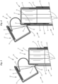
- a formed cigarette group consisting of (several) rows is the content of an inner pack, namely a sealing block 11 designed as a foil block.
- this preferably consists of a blank 12 made of foil, namely a moisture- and aroma-tight foil.
- the group of cigarettes 10 is preferably completely wrapped in the blank, i.e. on all sides, and thus forms a sealing block with an inner front wall 13, inner rear wall 14, inner side walls 15, inner bottom wall 16 and inner front wall 17.
- the blank 12 is designed or folded around the group of cigarettes 10 such that the inner front wall 17 is free of folds, i.e. forms a continuously closed wall.
- An opening aid 18 is attached in this area, which enables easy, in particular automatic, access to the contents of the pack.
- the foil block 11 forms a removal opening 19 in the front area.
- the removal opening 19 extends in the region of the inner end wall 17 and an adjoining, front-side section of the inner front wall 13.
- the removal opening 19 is preferably arranged centrally, with a (significantly) smaller width than the film block 11.
- the removal opening 19 is - when the pack is closed - covered by a closure means, in particular a closure tab 20.
- This preferably covers the removal opening 19 completely and preferably forms a strip-shaped projection all around with longitudinal strips 21 and transverse strips 22.
- An anchoring strip 23 is permanently connected to the film block 11, in particular as a leg of the closure tab 20 in the area of the inner rear wall 14.
- the aforementioned edge strips 21, 22, 23 are connected to the film block 11 by adhesive, each in an edge strip surrounding the removal opening 19. At least the longitudinal strips 21 and the transverse strip 22 are fixed with a removable and multi-acting adhesive, in particular PSA adhesive.
- the closure tab 20 is provided with a gripping or actuating tab 24 in one end region, namely in the region of a leg projecting into the inner front wall 13. This is free of glue at least on the side facing the inner front wall 13 and can thus be grasped.
- the actuating tab 24 preferably extends over the full width of the closure tab 20 as an edge strip thereof.
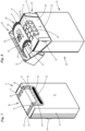
- actuating tab 24 in the embodiments shown is connected to a movable part of an outer packaging 25.
- the outer packaging here is a hinged box with a box part 26 and a lid 27. This is pivotally connected to the box part 26 in the area of a box rear wall 28 with a lid rear wall 29 via a linear joint 30.
- the closure tab 20 is connected to the lid 27 in such a way that when the lid is opened, the closure tab 20 also comes into the open position ( Fig. 3, Fig. 4 ).
- the actuating tab 24 of the closure tab 20 is connected to the lid, namely to a lid front wall 31.
- glue or by a glue strip 32 extending in the longitudinal direction of the actuating tab 24. This is attached to the outside of the actuating tab 24.
- the connection to the actuating tab 24 is made via the glue strip 32 in the closed position of the lid 27.
- an inner flap 33 is attached to the inside of the lid front wall 31.
- the actuating tab 24 is (permanently) connected to this. When the lid 27 is closed, the closure tab 20 also returns to the closed position ( Fig. 1 ) back.
- the foil block 11 or sealing block is according to Fig. 1 with an envelope fold in the area of the inner side walls 15.
- overlapping folding flaps are also formed, preferably as an envelope fold.
- the folding flaps are tightly connected to one another by thermal sealing.
- a support element is arranged within the film block 11, in particular a tray 34 of a known design, preferably with a front wall, side flaps and bottom wall.
- a special feature is that the removal opening 19 is at least partially free, i.e. without the opening flap 35 which is located in the area of the removal opening 19 during the preparation of the blank 12. This is part of the film in the area of the removal opening 19.
- the opening flap 35 is completely eliminated.
- the blank is therefore provided with a recess which forms the removal opening 19 in the finished package - foil block 11.
- a punching is made in the area of the unfolded blank, preferably in the area of a continuous foil web 36 for producing the blanks 12, which is precisely aligned with the design of the foil block 11, namely in the embodiment of the Fig. 1 to 3 a punched hole closed all around, which leads to a substantially rectangular recess corresponding to the removal opening 19, in particular with slightly converging edges - towards the actuating tab 24.
- the opening tab 35 is therefore a cut part and is eliminated.
- a U-shaped punch is made in the blank 12 or the film web 36 to form an opening.
- the resulting opening flap 35 remains connected to the blank 12 along an edge 37.
- the opening flap 35 is folded out of the area of the removal opening 19 and placed against a wall of the film block 11, in the present case ( Fig. 4 , Fig. 5 ) to the inside of the inner rear wall 14.
- a free opening is formed as a removal opening 19.
- the opening tab 35 is preferably connected to the wall of the film block 11, in particular by gluing and/or by thermal sealing, in the present case with two sealing strips 38.
- a (separate) special feature is the formation of the glue areas or the glue pattern for (removably) connecting the closure flap 20 to the foil block 11.
- the closure tab 20 is provided with a frame-like glue pattern surrounding the removal opening 19. This can be attached to the closure tab 20 (consisting of a separate blank) and/or to the blank 12 during manufacture.
- the glue pattern (preferably PSA glue), in particular with longitudinal strips 21, transverse strips 22 and anchoring strips 23, is designed with different adhesive effects, depending on the stress when opening and closing the film block 11.
- at least the transverse strip 22 is designed with a lower adhesive effect than the other sections of the glue pattern.
- the initial legs 39 of the longitudinal strips 21 are also designed with a lower adhesive effect, so that in particular the initiation of the opening process for the closure tab 20 is made easier.
- the other parts of the glue pattern, namely the longitudinal strips 21 and the transverse strip 22, are designed with a higher holding force, preferably with the same holding force throughout.
- the anchoring strip 23 can be designed with an even higher holding force in order to ensure the permanent fixation of the opening tab 20 to the film block 11.
- the different holding or connecting effects of the areas of the glue pattern can be achieved by appropriate selection of different types of glue and/or by different layer thicknesses and/or by different structures of the transverse strip 22 on the one hand and the longitudinal strip 21 on the other hand.
- This design of the glue connection of the closure flap 20 with the foil block 11 can also be used for conventional (sealed) packages and for packages corresponding Fig. 11 to Fig. 14
- the conventional packages referred to may be those in which the opening tab 35 remains in the initial position and is connected to the closure tab 20.
- the inner side walls 15 are formed by trapezoidal folding tabs.
- Fig. 7 to Fig. 10 deals with an alternative with regard to the design of the opening aid 18, but also with regard to the design of the film block 11. This has connecting seams in the area of the inner side walls 15 in the form of a fin seam. Furthermore, the inner bottom wall 16 is free of folds.
- a transverse seam 40 is located in the area of an inner rear wall 14, in particular in the form of a fin seam.
- the opening aid 18 is designed such that the blank 12 ( Fig. 9 ) has a free removal opening 19 all around. Accordingly, in the area of the film web 36, a complete punch is made to create a (removal) opening 19.
- the opening tab 35 created in this way is disposed of as waste. A free opening remains, in particular with opening edges converging towards the side of the actuating tab 24.
- the (PSA) adhesive is preferably applied to the inside of the closure flap 20.
- a glue pattern is created in the form of a closed frame with the legs or strips 21, 22, 23.
- a central area of the closure flap 20 is glue-free and preferably provided with a print 61.
- the glue fields or strips are slightly set back from the (removal) opening 19, so that a narrow, glue-free strip is preferably created all around, approximately 1.5 mm wide.
- the glue patterns are applied to connect the actuating tab 24 to the inside of the lid front wall 31.
- a closed, continuous glue strip 32 can be applied.
- the film for the film block 11 is multi-layered, consists in particular of two layers or individual films 42 and 43 ( Fig. 14 ). These layers or films 42, 43 are - predominantly - connected to one another over their entire surface by an adhesive layer 44 made of preferably non-detachable glue, so that in this area the individual films 42, 43 form an inseparable film unit.
- At least one of the individual films 42, 43 is designed to be aroma- and moisture-tight, preferably by means of a (metallic) barrier layer 45 applied by vapor deposition. This is located here within the multi-layer film.
- the adhesive layer 44 therefore connects the individual films 42, 43 in the area of the barrier layer 45.
- the multilayer film designed in the manner described can be provided with an opening aid 18 which corresponds to the previous embodiments.
- the structure of the film enables an opening aid 18 designed in a special way which is integrated into the film using the individual films 42, 43.
- the closure tab 20 is formed by the outer individual film 42.
- the inner individual film 43 is processed in such a way that it forms either an opening made during production as a removal opening 19 or an opening tab or an opening flap 35 that can be removed with the help of the closure tab 20 during the opening process. As shown, this is connected to the closure tab 20 by preferably full-surface adhesive (on the inside).
- the opening aid 18 is located in the area of the blank 12 ( Fig. 13 ), but preferably during the production of the (multi-layer) film - film web 36 - by targeted application of different types of glue, by forming glue-free areas between the individual films 42, 43 and by targeted application of dividing lines in the individual layers 42, 43.
- the attachment of the opening aid 18 is integrated into the manufacturing process of the film or the film web 36.
- areas are left out or provided with glue at the same time or offset, which are required for the functionality of the opening aid 18.
- PSA glue removable glue
- a partial or full coating with glue can be applied.
- a strip-shaped, rectangular free zone 46 is created with regard to the attachment of the glue layer 44. There is no glue in this area, i.e. neither the glue layer 44 nor the (PSA) glue of the opening aid 18. This is where the handle or actuation tab 24 is located.
- separating cuts or lines are made in the area of the opening aid 18 to be produced, preferably in the film finished with respect to the layers 42, 43, 44, 45.
- the separating lines made only in the area of one layer are preferably produced by laser and are thus limited in terms of effectiveness to the layer in question.
- the outer contour of the closure flap 20 consists of a preferably continuous, i.e. uninterrupted, essentially U-shaped cutting line 47 (only) in the area of the outer layer, i.e. the individual film 42.
- This cutting line extends with preferably approximately parallel legs in the area of the inner front wall 17 (at least partially) and an adjoining, front-side area of the inner front wall 13.
- the cutting line 47 runs with an end piece in the area of the inner rear wall 14.
- a transverse leg extends in the inner front wall 13 and limits the actuating tab 24.
- the cutting line 47 determines the outer contour of the locking tab 20.
- the inner individual film 43 forms the removal opening 19 by removing the opening tab formed by the individual film 43, which in the present example is connected to the closure flap 20, preferably by the correspondingly arranged glue layer 44.
- the contour of the opening tab 35 is determined by a preferably also approximately U-shaped weakening line 48, which is limited to the individual film 43 (including the thin barrier layer 45) by using appropriate technology (laser).
- the weakening line 48 can be designed as a perforation - with residual connections - but preferably as a continuous cutting line. In the present case, the arrangement is such that the ends of the cutting line 47 on the one hand and the weakening line 48 on the other hand - in the area of the inner rear wall 14 - end adjacent to one another.
- the glue pattern of the opening aid 18, i.e. the U-shaped glue pattern with longitudinal stripes 21 and transverse stripes 22, is designed with regard to the glue thickness in the manner described ( Fig. 5 )
- the glue strips 21, 22 are dimensioned such that the cutting line 47 and the weakening line 48 - the latter completely - lie in the area of the glue pattern 21, 22, of course with the exception of the contour for the actuating tab 24.
- the glue field preferably made of PSA glue, is, as can be seen from Fig. 13 and Fig. 14 visible, slightly wider than the distance between the cutting lines 47 and weakening lines 48, so that in this area the dividing lines are covered by the removable adhesive.
- the opening aid designed in this way can be operated by hand (by grasping the actuating tab 24).
- the actuating tab 24 is connected in the manner described to the inside of the lid 27 of an outer package 25 designed as a hinged box, so that automatic opening and closing is ensured.
- Fig. 12 As can be seen, during the opening process in the area of the removal opening 19 to be produced, the (multi-layer) film is completely separated from the composite.
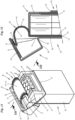
- the outer packaging 25 is preferably designed as a hard packaging, in particular as a hinged box. This can be provided without a collar, but alternatively also with a conventional collar 49 ( Fig. 8 ).
- the collar is provided with a front recess 50 which is delimited in the area of the front by lateral collar webs 51.
- the recess 50 - between the collar webs 51 - is preferably designed such that it extends to a closing edge 52 of the pack or box part 26. In this area - between the collar webs 51 - the closure tab 20 and in particular the actuating tab 24 are located.
- a contact pressure is exerted on the outside of the lid front wall 31, preferably in the area of a device (in particular a drying turret).
- the pressure is transferred by a special pressure piece specifically to the lid front wall 31 in the area of the connection with the actuating tab 24 - with the lid 27 closed.
- a pack with a collar 49 in the area between the collar webs 51 This makes it possible to use an inner lid flap 33 as the outer pack 25 in the hinged boxes, which preferably extends over the full (transverse) dimension of the lid front wall 31. A certain deformation of the lid front wall 31 is canceled out by the restoring forces of the material after the pressure load has ended.
- the opening aid is preferably produced completely in the area of a continuous film web 36.
- Fig. 15 and Fig. 16 concern different concepts for an opening aid according to Fig. 4 , Fig. 5 , i.e. with opening flaps 35 hanging on the blank 12.
- a shortened (residual) connection of the flap 35 formed by punching 53 with the film web 36 remains, i.e. a shortened edge 37.
- the opening flap 35 is grasped during the transport of the film web 35, lifted and folded over until it rests on the film web outside the area of the created removal opening 19. To do this, it is lifted in the area of a deflection - deflection roller 54 - with respect to a front edge.
- the opening flap 35 can now be grasped by a lifting element, in this case by a (curved) tapered lifting rail 55.
- the flap 35 is lifted and finally folded over by the transport of the film web 36. This creates the precisely positioned removal opening 19 in the area of the web.
- the closure tab 20 is applied to the film web 36 in the area of the removal opening 19 with exact alignment.
- the closure tab 20 is pressed as a separate cut from a carrier web 56 in the area of an acute-angled deflection onto the film web 36, namely on the (outer) side of the film web opposite the tab 35.
- the film web 35 then reaches the area of a separating station 57.
- the cuts 12 are separated from the web 36 one after the other by transversely directed separating knives 58.
- the film web 36 can be folded around a series of cigarette groups to form a continuous, tubular wrapper, from which packs - film block 11 - are separated by cross-section (in particular in conjunction with a sealing seam), in particular in the form of WO 2014/195016 removable manner.
- a special feature is that the work on the film web 36 and in particular the exact positioning of elements of the opening aid 18 are monitored by monitoring devices.
- Sensors in particular optoelectronic sensors 59, are preferably positioned in the area of the vertical transport path of the film web 36 in the area of a control station. These sensors 59 are designed in such a way that they detect the presence of the (removal) opening 19, both in terms of the correct relative position and in terms of the correct design (dimensions, contour). After passing the sensors 59, there is certainty that the opening 19 is correctly positioned.
- Another (stationary) inspection station with sensors 60 is installed on both sides of the web 36. These (electro-optical) sensors also detect the presence of the closure tab 20 in the correct relative position.
- the free side of the closure tab 20 is preferably provided with a print 61, namely on the inside of the closure tab 20, with advertising and/or informative information that can be detected by the sensors 60.
- the separating cut for producing the blanks 12 is preferably controlled by printing marks 62.
- the film web 36 is also assigned a sealing element 63 for applying the sealing strips 38.
- a sealing element 63 for applying the sealing strips 38.
- it is a rotatable sealing wheel with several (parallel) sealing jaws 64 arranged along the circumference. This element can also be controlled by the sensors 59 if necessary.
- Fig. 16 differs from the above embodiment in that the closure tabs 20 are already attached to the web 36 in a pre-placed transfer station - in the area of the punching 53, which is particularly attached first. After that, the already described process for lifting the opening tab 35 and folding this tab 35 takes place.
- the film web is also provided with Fig. 16 Control elements (sensors) are assigned which check in particular the presence and correct formation of the opening 19 and the presence of the closure tab 20.
- the device according to Fig. 17 is designed so that the opening flap 35 is removed so that a (removal) opening 19 is created on all sides.
- a punching unit 65 is provided on the film web 36, which in the present case consists of a punching roller 66 with a punching knife 67 and a counter roller 68.
- the punching knife 67 is designed as an approximately rectangular knife that is closed all around and which creates a corresponding opening 19 in the web 36 at a precise position.
- the web is then diverted. Inspection and control elements of the described design are positioned in the area of a vertical conveyor section, as well as a transfer station for attaching the closure tab 20 in the area of the openings 19.
- the pieces of material corresponding to the opening 19 produced in the punching station by the punching unit 65 are removed, in this case by a collecting funnel 69, in particular with a suction effect.
- a special manufacturing technology for the preparation of the film web 36 for the production of cuts of the film packages is described in Fig. 18 and Fig. 19
- the (sealing) film web 36 is preferably moved along upright and transverse transport tracks.
- a first (upright) track section 70 is provided for an upward movement of the web 36. This is deflected via deflection rollers 71, 72 into a preferably horizontal track section 73 and then back into a preferably downward track section 74.
- the closure tab 20 is preferably fed to the vertical track section 70 and applied to the film web 36 in a packaging-appropriate manner, preferably on the outside or top of the web.
- Preferably in the area of the horizontal track section 73 there is a special punching unit 65 with a punching roller 66, which preferably acts below the (horizontal) film web 36.
- a counter roller 68 is mounted above the web 36.
- the blanks of the closure tabs 20 are preferably arranged close together on a continuous carrier web 56. This is pulled off a reel 75.
- the carrier web 56 is fed to a transfer station 76.
- the closure tabs 20 are removed from the carrier web 56 and precisely transferred to the film web 36.
- the carrier web 56 is guided around an acute-angled deflection element 77, whereby the closure tab 20, which is adhesively adhered to the carrier web 56, is peeled off and transferred to the film web 36, which runs at an acute angle to one leg of the carrier web 56.
- the closure tab 20 is fixed in the exact position by a pressure roller 78.
- a counter element, in this case a support plate 79, is located opposite the pressure roller 78.
- a preferably closed separating line is applied to the free (lower) side of the film web 36 in the area of the respective closure tab 20, preferably by punching, which cuts out a piece of film - opening tab 35 - corresponding to the opening (removal opening 19).
- the punching unit 65 is precisely controlled in such a way that the opening is made in precise alignment with the closure tab 20 outside of the gluing, namely by separating cut exclusively in the area of the film web 36.
- the punching roller 66 is provided along the circumference with preferably several, in particular with two punching units, i.e. corresponding groups of punching knives 80. These are preferably designed as a closed knife frame for producing a closed separating line in the film web 36.
- the opening flap 35 is removed by suction.
- the punching roller 66 is preferably provided with suction holes 81 in the area of the punching blades 80. These (several) suction holes are located within the surface area of the opening flap 35, so that when negative pressure is applied, it is fixed to the circumference of the punching roller 66 and is carried along when the latter rotates.
- the opening flap 35 is released by venting and can be disposed of.
- a special measure is provided for this: On the underside of the punching roller 66 or underneath it there is a suction unit 82.
- the suction holes 81 of the punching roller 66 are preferably controlled in such a way that a switchover to compressed air takes place in the lower part of the rotary movement. Compressed air is therefore transmitted via the suction holes 81, which leads to the opening flap 35 being lifted off and transferred to the suction unit 82. This takes the piece of film 35 into a suction channel 83.
- the film web prepared in this way is fed to a separating station in the manner described for producing the cut pieces or film packages.
- the carrier web 56 freed from the closure tabs 20 is returned and taken up by a collecting reel 84.
- the carrier web 56 is driven in this area without closure tabs 20 by a drive roller 85.
- the carrier web 56 is therefore pulled over the deflection element 77.
- Monitoring and control elements are important for the correct positioning of the closure tab 20 and/or opening 19 in the preferably continuously driven film web 36.
- the precise positional transfer of the closure tab from the carrier web 56 to the film web 36 is monitored and controlled by sensors (not shown), preferably in conjunction with print marks on the film web 36.
- a first (optoelectronic) sensor 86 becomes active, preferably in the area of the upright web section 17, specifically on the side where the closure tab 20 is arranged.
- the sensor 86 is arranged and active in such a way that at least one preferably transverse edge of the closure tab 20 is detected.
- a signal for controlling the punching unit 65 is derived from this, namely with regard to a precise application of the dividing line for producing the opening 19.
- a further sensor 87 is effective after the punching unit 65, namely on the inside of the film web 36 - preferably in the area of the downward-facing web section 74 - to detect the punched-out or opening formed.
- This sensor 87 also detects the presence of the closure tab 20 in an exact relative position to the (removal) opening 19.
- the free inside of the closure tab 20 is provided with markings and/or colorings that ensure quick, reliable detection by the sensor 87 compared to the differently designed film web 36.
Landscapes
- Engineering & Computer Science (AREA)
- Mechanical Engineering (AREA)
- Packaging Of Annular Or Rod-Shaped Articles, Wearing Apparel, Cassettes, Or The Like (AREA)
- Making Paper Articles (AREA)
- Cartons (AREA)
- Packages (AREA)
Description
- Die Erfindung betrifft Packungen für Zigaretten mit den Merkmalen des Oberbegriffs des Anspruchs 1.
- Dichtpackungen für Zigaretten bestehen aus einem Dichtblock als Innenpackung und einer Außenpackung, insbesondere in der Ausführung als Klappschachtel. Der Dichtblock ist mit einer Öffnungshilfe versehen, bei der eine mehrfach benutzbare, durch geeigneten Kleber fixierte Verschlusslasche durch Abziehen in die Öffnungsstellung und danach wieder in die Schließstellung gebracht werden kann. In der Öffnungsstellung ist eine Entnahmeöffnung des Dichtblocks freigelegt.
- Bekannt sind auch bereits Packungen, bei denen die Verschlusslasche mit einem Betätigungslappen an der Innenseite eines Deckels - Deckel-Vorderwand - einer Klappschachtel fixiert ist. Beim Öffnen des Deckels der Außenpackung wird demnach die Verschlusslasche (selbsttätig) mit in die Öffnungsstellung bewegt. Beim Schließen des Deckels wird so auch die Verschlussstellung geschaffen (
WO 2013/120913 ). - In der
WO 02/079051 A1 - Es ist Aufgabe der Erfindung, die Technologie hinsichtlich des Aufbaus, der Funktionalität und der Herstellung von Dichtpackungen für Zigaretten weiterzuentwickeln und zu verbessern, insbesondere hinsichtlich der Struktur der Öffnungshilfe.
- Zur Lösung dieser Aufgabe ist die erfindungsgemäße Packung mit den Merkmalen des Anspruchs 1 ausgebildet.
- Eine Besonderheit der Innovation besteht demnach darin, dass die Entnahmeöffnung nicht beim erstmaligen Öffnen der Packung durch Entfernen eines Öffnungsstücks bzw. einer Öffnungslasche des Dichtblocks entsteht. Vielmehr wird der Dichtblock mit einer vorgefertigten Entnahmeöffnung versehen. Vorzugsweise wird diese - wenn der Dichtblock aus einem Folienzuschnitt gefertigt ist - im Bereich einer (fortlaufenden) Folienbahn für die Herstellung von Zuschnitten für den Dichtblock angebracht, und zwar durch Schneiden oder Stanzen in einer Position, die der packungsgemäßen Stellung entspricht.
- Die Öffnung bzw. Entnahmeöffnung ist (vollständig) von einer Verschlusslasche abgedeckt. Überdeckungsränder sind mittels Dauerkleber, vorzugsweise Pressure Sensitive Adhesives (PSA-Kleber) mit einem die Öffnung umgebenden Rand der Folie verbunden. Vorzugsweise wird die Verschlusslasche ebenfalls im Bereich der Folienbahn positionsgerecht angebracht, und zwar alternativ vor oder nach dem Herstellen der (Entnahme-)Öffnung. Besonders vorteilhaft ist ein Verfahren, bei dem zuerst die Verschlusslasche in packungsgerechter Position an der Folienbahn angebracht und sodann im Bereich der Verschlusslasche eine die Entnahmeöffnung der Packung bildende Öffnung hergestellt wird durch Stanzen oder durch Laser.
- Gemäß einer Ausführungsform ist die Öffnungshilfe für den Dichtblock in die aus mindestens zwei Lagen bzw. Einzelfolien bestehende (Laminat-)Folie integriert. Von den überwiegend vollflächig miteinander (durch Leim) verbundenen Lagen bzw. Folien, bildet eine Lage bzw. Einzelfolie (an der Außenseite des Folienblocks) eine Verschlusslasche, die andere (innenliegende) Lage bzw. Einzelfolie bildet die Entnahmeöffnung. Insbesondere ist durch entsprechende Stanzung im Bereich der inneren Lage bzw. Einzelfolie eine Öffnungslasche gebildet, die aufgrund Verbindung mit der Verschlusslasche der anderen Einzelfolie bei Betätigen der Öffnungshilfe in eine Öffnungsstellung gebracht wird und so die Entnahmeöffnung schafft bzw. frei gibt. Eine Besonderheit bei dieser Ausführung ist die ausgewählte Positionierung von Leimfeldern, insbesondere in einer U-förmigen Flächenstruktur, zur (lösbaren) Verbindung von Elementen der Öffnungshilfe miteinander.
- Eine Besonderheit der Öffnungshilfe besteht darin, dass eine vorzugsweise sich über die volle Breite der Verschlusslasche erstreckende end- bzw. randseitige Griff- oder Betätigungslasche frei von Kleber und vorzugsweise einlagig ausgebildet ist. Die Betätigungslasche ist insbesondere über eine Leimverbindung an der Innenseite einer Deckel-Vorderwand einer Klappschachtel fixiert, sodass beim Öffnen des Deckels die Verschlusslasche in eine Öffnungsstellung gelangt.
- Ausführungsbeispiele der Packungen, von Verpackungsmaterial sowie Verfahren und Vorrichtungen werden nachfolgend anhand der Zeichnungen erläutert. Es zeigt:
- Fig. 1
- einen Folienblock bzw. Dichtblock mit Zigaretten in perspektivischer Darstellung,
- Fig. 2
- eine komplette (Zigaretten-)Packung in geöffneter Stellung, ebenfalls in Perspektive,
- Fig. 3
- einen stirnseitigen Teilbereich der Packung gemäß
Fig. 2 im Vertikalschnitt III-III, bei vergrößertem Maßstab, - Fig. 4
- eine Darstellung analog
Fig. 3 für ein anderes Ausführungsbeispiel, - Fig. 5
- einen ausgebreiteten Zuschnitt für einen Folienblock gemäß
Fig. 1 in der Ausführung gemäßFig. 4 , - Fig. 6
- einen Querschnitt VI-VI des Zuschnitts in
Fig. 5 , bei vergrößertem Maßstab, - Fig. 7
- einen Zigaretten-(Dicht-)Block einer anderen Ausführungsform in Perspektive,
- Fig. 8
- eine (Zigaretten-)Packung mit Klappschachtel in geöffneter Stellung in perspektivischer Darstellung,
- Fig. 9
- einen Zuschnitt für eine Innen-Packung bzw. einen Folienblock in der Ausführung gemäß
Fig. 7 , - Fig. 10
- einen Querschnitt X-X des Zuschnitts gemäß
Fig. 9 , in vergrößertem Maßstab, - Fig. 11
- eine weitere Ausführungsform einer (Zigaretten-)Packung bei geöffnetem Deckel einer Außenpackung in Perspektive,
- Fig. 12
- einen Vertikalschnitt eines deckelseitigen Bereichs der Packung gemäß
Fig. 11 in der Schnittebene XII-XII in vergrößertem Maßstab, - Fig. 13
- einen Zuschnitt für eine Innenpackung bzw. einen Folienblock in der Ausführung gemäß
Fig. 11, Fig. 12 , - Fig. 14
- einen Querschnitt XIV-XIV durch den Zuschnitt gemäß
Fig. 13 in vergrößertem Maßstab, - Fig. 15
- einen Ausschnitt einer Einrichtung zum Fertigen von Folienbahnen für die Herstellung von Zuschnitten gemäß
Fig. 5 in perspektivischer Darstellung, - Fig. 16
- einen Ausschnitt analog
Fig. 15 mit einer Fertigungsalternative, - Fig. 17
- einen Ausschnitt einer Fertigungseinrichtung für Zuschnitte mit den Merkmalen der
Fig. 4 , - Fig. 18
- eine weitere Ausführung einer Einrichtung zum Vorbereiten von Folienbahnen in schematischer Seitenansicht,
- Fig. 19
- einen Ausschnitt XIX der Vorrichtung gemäß
Fig. 18 in vergrößertem Maßstab. - Die Ausführungsbeispiele der Zeichnungen befassen sich mit der Gestaltung von Packungen für Zigaretten 10. Eine formierte, nämlich aus (mehreren) Reihen bestehende Zigarettengruppe ist Inhalt einer Innenpackung, nämlich eines als Folienblock ausgebildeten Dichtblocks 11.
- Dieser besteht vorliegend aus vorzugsweise einem Zuschnitt 12 aus Folie, nämlich aus einer feuchtigkeits- und aromadichten Folie. Die Gruppe der Zigaretten 10 wird vorzugsweise vollständig, d. h. an allen Seiten, von dem Zuschnitt umhüllt, bildet demnach einen Dichtblock mit Innen-Vorderwand 13, Innen-Rückwand 14, Innen-Seitenwänden 15, Innen-Bodenwand 16 und Innen-Stirnwand 17. Der Zuschnitt 12 ist so ausgebildet bzw. um die Gruppe der Zigaretten 10 herumgefaltet, dass die Innen-Stirnwand 17 frei von Faltungen ist, also eine durchgehend geschlossene Wandung bildet. In diesem Bereich ist eine Öffnungshilfe 18 angebracht, die den leichten, insbesondere selbsttätigen Zugang zum Packungsinhalt ermöglicht. Der Folienblock 11 bildet zu diesem Zweck eine Entnahmeöffnung 19 im stirnseitigen Bereich. Vorzugsweise erstreckt sich die Entnahmeöffnung 19 im Bereich der Innen-Stirnwand 17 und einem anschließenden, stirnseitigen Teilstück der Innen-Vorderwand 13. Die Entnahmeöffnung 19 ist vorzugsweise mittig angeordnet, mit (deutlich) geringerer Breite als der Folienblock 11.
- Die Entnahmeöffnung 19 ist - bei geschlossener Packung - überdeckt von einem Verschlussmittel, insbesondere einer Verschlusslasche 20. Diese überdeckt die Entnahmeöffnung 19 vorzugsweise vollständig und bildet vorzugsweise ringsherum einen streifenförmigen Überstand mit Längsstreifen 21 und Querstreifen 22. Ein Verankerungsstreifen 23 ist dauerhaft mit dem Folienblock 11 verbunden, insbesondere als Schenkel der Verschlusslasche 20 im Bereich der Innen-Rückwand 14. Die vorgenannten Randstreifen 21, 22, 23 sind durch Klebung mit dem Folienblock 11 verbunden, jeweils in einem die Entnahmeöffnung 19 umgebenden Randstreifen. Mindestens die Längsstreifen 21 und der Querstreifen 22 sind mit lösbarem und mehrfach wirkendem Kleber fixiert, insbesondere PSA-Kleber.
- Die Verschlusslasche 20 ist in einem Endbereich, nämlich im Bereich eines in die Innen-Vorderwand 13 ragenden Schenkels mit einer Griff- bzw. Betätigungslasche 24 versehen. Diese ist mindestens an der der Innen-Vorderwand 13 zugekehrten Seite leimfrei und kann dadurch erfasst werden. Die Betätigungslasche 24 erstreckt sich vorzugsweise über die volle Breite der Verschlusslasche 20 als Randstreifen derselben.
- Eine Besonderheit besteht darin, dass die Betätigungslasche 24 bei den gezeigten Ausführungsbeispielen mit einem bewegbaren Teil einer Außenpackung 25 verbunden ist. Die Außenpackung ist hier eine Klappschachtel mit Schachtelteil 26 und Deckel 27. Dieser ist im Bereich einer Schachtel-Rückwand 28 mit einer Deckel-Rückwand 29 über ein Liniengelenk 30 schwenkbar mit dem Schachtelteil 26 verbunden.
- Die Verschlusslasche 20 ist mit dem Deckel 27 verbunden, derart, dass beim Öffnen desselben die Verschlusslasche 20 ebenfalls in Öffnungsstellung gelangt (
Fig. 3, Fig. 4 ). Zu diesem Zweck ist die Betätigungslasche 24 der Verschlusslasche 20 mit dem Deckel, nämlich mit einer Deckel-Vorderwand 31, verbunden. Insbesondere durch Leim bzw. durch einen sich in Längsrichtung der Betätigungslasche 24 erstreckenden Leimstreifen 32. Dieser ist an der Außenseite der Betätigungslasche 24 angebracht. Bei der Herstellung der Packung bzw. beim Einführen des Folienblocks 11 in die Außenpackung 25 wird in der Schließstellung des Deckels 27 die Verbindung mit der Betätigungslasche 24 über den Leimstreifen 32 hergestellt. Vorzugsweise ist an der Innenseite der Deckel-Vorderwand 31 ein Deckel-Innenlappen 33 angebracht. Mit diesem ist die Betätigungslasche 24 (dauerhaft) verbunden. Beim Schließen des Deckels 27 kehrt auch die Verschlusslasche 20 in die Schließstellung (Fig. 1 ) zurück. - Der Folienblock 11 bzw. Dichtblock ist gemäß
Fig. 1 mit einer Kuvertfaltung im Bereich der Innen-Seitenwände 15 ausgebildet. Auch im Bereich der Bodenwand 16 sind einander überdeckende Faltlappen, vorzugsweise als Kuvertfaltung, gebildet. Die Faltlappen sind durch thermisches Siegeln dicht miteinander verbunden. Weiterhin ist innerhalb des Folienblocks 11 ein Stützorgan angeordnet, insbesondere ein Tray 34 bekannter Ausführung, vorzugsweise mit Vorderwand, Seitenlappen und Bodenwand. - Eine Besonderheit besteht darin, dass die Entnahmeöffnung 19 mindestens teilweise frei ist, also ohne den bei der Vorbereitung des Zuschnitts 12 im Bereich der Entnahmeöffnung 19 liegenden Öffnungslappen 35. Dieser ist Teil der Folie im Bereich der Entnahmeöffnung 19. Bei dem Ausführungsbeispiel gemäß
Fig. 1 bis Fig. 3 ist der Öffnungslappen 35 vollständig beseitigt. Der Zuschnitt ist demnach mit einer Ausnehmung versehen, die bei der fertigen Packung - Folienblock 11 - die Entnahmeöffnung 19 bildet. Zu diesem Zweck wird im Bereich des ungefalteten Zuschnitts, vorzugsweise im Bereich einer fortlaufenden Folienbahn 36 zum Herstellen der Zuschnitte 12 ein exakt auf die Gestaltung des Folienblocks 11 ausgerichtete Stanzung angebracht, und zwar bei dem Ausführungsbeispiel derFig. 1 bis 3 eines ringerherum geschlossene Stanzung, die zu einer im Wesentlichen rechteckigen Ausnehmung entsprechend der Entnahmeöffnung 19 führt, insbesondere mit leicht konvergierenden - zur Betätigungslasche 24 - Rändern. Der Öffnungslappen 35 fällt demnach als Zuschnittteil an und wird beseitigt. - Alternativ (
Fig. 4 ,Fig. 5, Fig. 6 ) wird eine U-förmige Stanzung im Zuschnitt 12 bzw. der Folienbahn 36 angebracht zur Bildung einer Öffnung. Der entstehende Öffnungslappen 35 bleibt entlang einer Kante 37 in Verbindung mit dem Zuschnitt 12. Der Öffnungslappen 35 wird hier aus dem Bereich der Entnahmeöffnung 19 herausgefaltet und an eine Wandung des Folienblocks 11 angelegt, vorliegend (Fig. 4 ,Fig. 5 ) an die Innenseite der Innen-Rückwand 14. Auch hier ist demnach eine freie Öffnung gebildet als Entnahmeöffnung 19. Der Öffnungslappen 35 wird vorzugsweise mit der Wandung des Folienblocks 11 verbunden, insbesondere durch Verklebung und/oder durch thermisches Siegeln, vorliegend mit zwei Siegelstreifen 38. - Eine (eigenständige) Besonderheit ist die Ausbildung der Leimbereiche bzw. des Leimbildes zum (lösbaren) Verbinden der Verschlusslasche 20 mit dem Folienblock 11. Wie insbesondere aus
Fig. 5 ersichtlich, ist die Verschlusslasche 20 mit einem rahmenartig ausgebildeten, die Entnahmeöffnung 19 umgebenden Leimbild versehen. Dieses kann bei der Herstellung an der (aus einem gesonderten Zuschnitt bestehenden) Verschlusslasche 20 und/oder am Zuschnitt 12 angebracht sein. - Das Leimbild (vorzugsweise PSA-Kleber), insbesondere mit Längsstreifen 21, Querstreifen 22 und Verankerungsstreifen 23, ist mit unterschiedlicher Haftwirkung ausgebildet, entsprechend der Beanspruchung beim Öffnen und beim Schließen des Folienblocks 11. Vorzugsweise ist mindestens der Querstreifen 22 mit geringerer Haftwirkung ausgebildet als die übrigen Abschnitte des Leimbildes. Vorliegend sind auch Anfangsschenkel 39 der Längsstreifen 21 mit geringerer Haftwirkung ausgebildet, sodass insbesondere die Einleitung des Öffnungsvorgangs für die Verschlusslasche 20 erleichtert ist. Die weiteren Teile des Leimbildes, nämlich die Längsstreifen 21 und der Querstreifen 22, sind mit höherer Haltkraft ausgebildet, vorzugsweise durchgängig mit derselben Haltekraft. Alternativ kann der Verankerungsstreifen 23 mit nochmals erhöhter Haltekraft ausgebildet sein, um die dauerhafte Fixierung der Öffnungslasche 20 am Folienblock 11 zu gewährleisten.
- Die unterschiedlichen Halte- bzw. Verbindungswirkungen der Bereiche des Leimbildes können durch entsprechende Auswahl unterschiedlicher Leimarten bewirkt werden und/oder durch unterschiedliche Schichtdicken und/oder durch unterschiedliche Strukturen des Querstreifens 22 einerseits und der Längsstreifen 21 andererseits erreicht werden.
- Diese Gestaltung der Leimverbindung der Verschlusslasche 20 mit dem Folienblock 11 kann auch bei herkömmlichen (Dicht-)Packungen und bei Packungen entsprechend
Fig. 11 bis Fig. 14 angewendet werden. Bei den angesprochenen herkömmlichen Packungen kann es sich um solche handeln, bei denen der Öffnungslappen 35 in der Ausgangsstellung bleibt und mit der Verschlusslasche 20 verbunden ist. - Bei dem Folienblock 11 gemäß
Fig. 1, Fig. 2 und dem hierzu passenden Zuschnitt 12 gemäßFig. 5 sind die Innen-Seitenwände 15 durch trapezförmige Faltlappen gebildet.Fig. 7 bis Fig. 10 befasst sich mit einer Alternative hinsichtlich der Ausbildung der Öffnungshilfe 18, aber auch hinsichtlich der Ausbildung des Folienblocks 11. Dieser weist im Bereich der Innen-Seitenwände 15 Verbindungsnähte in der Ausführung als Flossennaht auf. Des Weiteren ist hier die Innen-Bodenwand 16 frei von Faltungen. Eine Quernnaht 40 befindet sich im Bereich einer Innen-Rückwand 14, insbesondere in der Ausführung als Flossennaht. - Die Öffnungshilfe 18 ist bei diesem Ausführungsbeispiel so ausgebildet, dass der Zuschnitt 12 (
Fig. 9 ) eine ringsherum freie Entnahmeöffnung 19 erhält. Es wird demnach - im Bereich der Folienbahn 36 - eine komplette Stanzung angebracht unter Erzeugung einer (Entnahme-)Öffnung 19. Der dabei entstehende Öffnungslappen 35 wird als Abfallstück entsorgt. Es bleibt eine freie Öffnung, insbesondere mit zur Seite der Betätigungslasche 24 konvergierenden Öffnungsrändern. - Bei den Ausführungsbeispielen mit einer Verschlusslasche 20 aus gesondertem Zuschnitt ist vorzugsweise der (PSA-)Kleber an der Innenseite der Verschlusslasche 20 angebracht. Vorzugsweise wird ein Leimbild in der Ausführung eines geschlossenen Rahmens geschaffen mit den Schenkeln bzw. Streifen 21, 22, 23. Ein mittlerer Bereich der Verschlusslasche 20 ist leimfrei und vorzugsweise mit einer Bedruckung 61 versehen. Die Leimfelder bzw. -streifen sind gegenüber der (Entnahme-)Öffnung 19 geringfügig zurückgesetzt, sodass ein schmaler, leimfreier Streifen vorzugsweise ringsherum entsteht, etwa von 1,5 mm Breite.
- Im Bereich eines leimfreien Teils der Verschlusslasche 20, nämlich im Bereich der Betätigungslasche 24, sind die Leimbilder angebracht zum Verbinden der Betätigungslasche 24 mit der Innenseite der Deckel-Vorderwand 31. Es sind zwei Alternativen gezeigt: Es kann ein geschlossener, durchgehender Leimstreifen 32 angebracht sein. Alternativ ist eine Anzahl von nebeneinander liegenden Leimpunkten 41.
- Eine hinsichtlich des Dichtblocks bzw. Folienblocks 11 und insbesondere im Bereich der Öffnungshilfe 18 besondere Ausführung ist in
Fig. 11 bis Fig. 13 dargestellt. Die Folie für den Folienblock 11 ist mehrlagig ausgebildet, besteht insbesondere aus zwei Lagen bzw. Einzelfolien 42 und 43 (Fig. 14 ). Diese Lagen bzw. Folien 42, 43 sind - überwiegend - vollflächig durch eine Leimschicht 44 aus vorzugsweise nicht lösbarem Leim miteinander verbunden, sodass in diesem Bereich die Einzelfolien 42, 43 eine nicht trennbare Folieneinheit bilden. - Vorzugsweise ist mindestens eine der Einzelfolien 42, 43, vorliegend die innenseitige Einzelfolie 43, als aroma- und feuchtigkeitsdicht ausgebildet, vorzugsweise durch eine durch Aufdampfen angebrachte (metallische) Sperrschicht 45. Diese liegt hier innerhalb der mehrlagigen Folie. Die Leimschicht 44 verbindet demnach die Einzelfolien 42, 43 im Bereich der Sperrschicht 45.
- Die in beschriebener Weise ausgebildete mehrlagige Folie kann mit einer Öffnungshilfe 18 versehen sein, die den bisherigen Ausführungsbeispielen entspricht. Die Struktur der Folie ermöglicht aber eine in besonderer Weise ausgebildete Öffnungshilfe 18, die in die Folie unter Nutzung der Einzelfolien 42, 43 integriert ist.
- Die Verschlusslasche 20 wird durch die außenliegende Einzelfolie 42 gebildet. Die innenliegende Einzelfolie 43 ist so bearbeitet, dass sie entweder eine bei der Fertigung angebrachte Öffnung als Entnahmeöffnung 19 oder eine mit Hilfe der Verschlusslasche 20 beim Öffnungsvorgang heraustrennbare Öffnungslasche bzw. einen Öffnungslappen 35 bildet. Dieser ist, wie gezeigt, durch vorzugsweise vollflächige Klebung (innenseitig) mit der Verschlusslasche 20 verbunden.
- Die Öffnungshilfe 18 wird bei dieser Packung im Bereich des Zuschnitts 12 (
Fig. 13 ), vorzugsweise aber bei der Herstellung der (mehrlagigen) Folie - Folienbahn 36 - hergestellt, und zwar durch gezielte Anbringung unterschiedlicher Leimtypen, durch Bildung von leimfreien Bereichen zwischen den Einzelfolien 42, 43 und durch gezieltes Anbringen von Trennlinien in den einzelnen Lagen 42, 43. - Die Anbringung der Öffnungshilfe 18 ist in den Herstellungsprozess der Folie bzw. der Folienbahn 36 integriert. Vorzugsweise werden beim Zusammenfügen der Lagen bzw. Einzelfolien 42, 43 Flächen ausgespart bzw. zeitgleich oder versetzt mit Leim versehen, die zur Funktionalität der Öffnungshilfe 18 erforderlich sind. Bei dem vorliegenden Beispiel ist eine vorzugsweise U-förmige Fläche zwischen den Einzelfolien 42, 43 mit lösbarem Leim (PSA-Kleber) versehen, analog zu dem beschriebenen Ausführungsbeispiel zur Bildung von Längsstreifen 21, Querstreifen 22. Alternativ kann eine Teil- oder Vollbeschichtung mit Leim angebracht sein. Des Weiteren ist hinsichtlich der Anbringung der Leimschicht 44 eine - streifenförmige, rechteckige - Freizone 46 geschaffen. In diesem Bereich befindet sich kein Leim, also weder die Leimschicht 44 noch der (PSA-)Leim der Öffnungshilfe 18. Hier befindet sich die Griff- bzw. Betätigungslasche 24.
- Zur Bildung von Verschlusslasche 20 und/oder Öffnungslappen 35 werden Trennschnitte bzw. -linien im Bereich der herzustellenden Öffnungshilfe 18 angebracht, vorzugsweise in der hinsichtlich der Lagen 42, 43, 44, 45 fertiggestellten Folie. Die lediglich im Bereich einer Lage angebrachten Trennlinien werden vorzugsweise durch Laser hergestellt und dadurch hinsichtlich der Wirksamkeit auf die betreffende Lage beschränkt.
- Die Außenkontur der Verschlusslasche 20 besteht aus einer vorzugsweise durchgehenden, also ununterbrochenen, im Wesentlichen U-förmigen Schnittlinie 47 (nur) im Bereich der äußeren Lage, also der Einzelfolie 42. Diese Schnittlinie erstreckt sich mit vorzugsweise etwa parallelen Schenkeln im Bereich der Innen-Stirnwand 17 (mindestens teilweise) und einem anschließenden, stirnseitigen Bereich der Innen-Vorderwand 13. Bei dem Ausführungsbeispiel der
Fig. 13 verläuft die Schnittlinie 47 mit einem Endstück im Bereich der Innen-Rückwand 14. Ein quergerichteter Schenkel erstreckt sich in der Innen-Vorderwand 13 und begrenzt die Betätigungslasche 24. Die Schnittlinie 47 bestimmt die Außenkontur der Verschlusslasche 20. - Die innenliegende Einzelfolie 43 bildet die Entnahmeöffnung 19 durch Beseitigen der von der Einzelfolie 43 gebildeten Öffnungslappen, der bei dem vorliegenden Beispiel mit der Verschlusslasche 20 verbunden ist, vorzugsweise durch die entsprechend angeordnete Leimschicht 44. Die Kontur des Öffnungslappens 35 wird durch eine vorzugsweise ebenfalls etwa U-förmige Schwächungslinie 48 bestimmt, die durch Anwendung entsprechender Technologien (Laser) auf die Einzelfolie 43 (einschließlich der dünnen Sperrschicht 45) begrenzt ist. Die Schwächungslinie 48 kann als Perforation - mit Restverbindungen -, vorzugsweise aber als durchgehende Schnittlinie ausgebildet sein. Vorliegend ist die Anordnung so getroffen, dass die Enden der Schnittlinie 47 einerseits und der Schwächungslinie 48 andererseits - im Bereich der Innen-Rückwand 14 - benachbart zueinander enden.
- Das Leimbild der Öffnungshilfe 18, also das U-förmige Leimbild mit Längsstreifen 21 und Querstreifen 22, ist hinsichtlich der Leimstärke in der beschriebenen Weise (
Fig. 5 ) ausgebildet. Die Leimstreifen 21, 22 sind so bemessen, dass die Schnittlinie 47 und die Schwächungslinie 48 - letztere komplett - im Bereich des Leimbildes 21, 22 liegen, natürlich mit Ausnahme der Kontur für die Betätigungslasche 24. Das Leimfeld aus vorzugsweise PSA-Kleber ist, wie ausFig. 13 und Fig. 14 ersichtlich, geringfügig breiter als der Abstand zwischen den Schnittlinien 47 und Schwächungslinien 48, sodass in diesem Bereich die Trennlinien durch den lösbaren Kleber überdeckt sind. - Die so ausgebildete Öffnungshilfe kann von Hand betätigt werde (durch Erfassen der Betätigungslasche 24). Bei dem vorliegenden Beispiel ist die Betätigungslasche 24 in der beschriebenen Weise mit der Innenseite des Deckels 27 einer als Klappschachtel ausgebildeten Außenpackung 25 verbunden, sodass ein selbsttätiges Öffnen und Schließen gewährleistet ist. Wie insbesondere aus
Fig. 12 ersichtlich, wird beim Öffnungsvorgang im Bereich der herzustellenden Entnahmeöffnung 19 die (mehrlagige) Folie komplett aus dem Verbund herausgetrennt. - Die Außenpackungen 25 sind vorzugsweise als Hartpackungen ausgebildet, insbesondere als Klappschachtel. Diese kann ohne Kragen, alternativ aber auch mit einem üblichen Kragen 49 versehen sein (
Fig. 8 ). Der Kragen ist mit einer frontseitigen Ausnehmung 50 versehen, die im Bereich der Frontseite durch seitliche Kragenstege 51 begrenzt ist. Vorzugsweise ist die Ausnehmung 50 - zwischen den Kragenstegen 51 - so ausgebildet, dass sie sich bis zu einer Schließkante 52 der Packung bzw. des Schachtelteils 26 erstreckt. In diesem Bereich - zwischen den Kragenstegen 51 - befindet sich die Verschlusslasche 20 und insbesondere die Betätigungslasche 24. - Bei Packungen mit einer Fixierung der Betätigungslasche 24 der Öffnungshilfe 18 an der Innenseite der Deckel-Vorderwand 31 wird vorzugsweise nach Komplettierung der Packung ein Anpressdruck auf die Außenseite der Deckel-Vorderwand 31 ausgeübt, vorzugsweise im Bereich einer Vorrichtung (insbesondere Trockenrevolver). Der Druck wird durch ein besonderes Druckstück gezielt auf die Deckel-Vorderwand 31 im Bereich der Verbindung mit der Betätigungslasche 24 - bei geschlossenem Deckel 27 - übertragen. Bei einer Packung mit Kragen 49 im Bereich zwischen den Kragenstegen 51. Dadurch ist es möglich, bei den Klappschachteln als Außenpackung 25 einen Deckel-Innenlappen 33 einzusetzen, der sich vorzugsweise über die volle (Quer-)Abmessung der Deckel-Vorderwand 31 erstreckt. Eine gewisse Verformung der Deckel-Vorderwand 31 wird durch die Rückstellkräfte des Materials nach Beendigung der Druckbelastung aufgehoben.
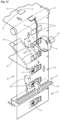
- Die Öffnungshilfe wird vorzugsweise komplett im Bereich einer fortlaufenden Folienbahn 36 hergestellt.
Fig. 15 undFig. 16 betreffen unterschiedliche Konzepte für eine Öffnungshilfe gemäßFig. 4 ,Fig. 5 , also mit am Zuschnitt 12 hängenden Öffnungslappen 35. GemäßFig. 15 bleibt eine verkürzte (Rest-)Verbindung des durch Stanzung 53 gebildeten Lappens 35 mit der Folienbahn 36, also eine verkürzte Kante 37. Der Öffnungslappen 35 wird während des Transports der Folienbahn 35 erfasst, abgehoben und umgelegt bis zur Anlage an der Folienbahn außerhalb des Bereichs der geschaffenen Entnahmeöffnung 19. Hierzu wird im Bereich einer Umlenkung - Umlenkwalze 54 - hinsichtlich einer frontseitigen Kante angehoben. Der Öffnungslappen 35 kann nun von einem Huborgan erfasst werden, vorliegend von einer (gekrümmten) spitz zulaufenden Hubschiene 55. Durch den Transport der Folienbahn 36 wird der Lappen 35 angehoben und schließlich umgelegt. Es entsteht dadurch im Bereich der Bahn die positionsgenau liegende Entnahmeöffnung 19. - Nachfolgend wird - im Bereich eines vertikalen Transportabschnitts der Folienbahn 36 - die Verschlusslasche 20 im Bereich der Entnahmeöffnung 19 unter exakter Ausrichtung auf die Folienbahn 36 aufgebracht. Die Verschlusslasche 20 wird als gesonderter Zuschnitt von einer Trägerbahn 56 im Bereich einer spitzwinkligen Umlenkung an die Folienbahn 36 angedrückt, und zwar auf der zu der Lasche 35 gegenüberliegenden (äußeren) Seite der Folienbahn. Danach gelangt die Folienbahn 35 in den Bereich einer Trennstation 57. Hier werden die Zuschnitte 12 durch quergerichtete Trennmesser 58 nacheinander von der Bahn 36 abgetrennt. Alternativ kann die Folienbahn 36 um eine Folge von Zigarettengruppen herumgefaltet werden unter Bildung einer fortlaufenden, schlauchförmigen Umhüllung, von denen durch Querschnitt (insbesondere in Verbindung mit einer Siegelnaht) Packungen - Folienblock 11 - abgetrennt werden, insbesondere in der aus
WO 2014/195016 entnehmbaren Weise. - Eine Besonderheit liegt darin, dass die Arbeiten an der Folienbahn 36 und insbesondere die exakte Positionierung von Elementen der Öffnungshilfe 18 durch Überwachungsorgane kontrolliert werden. So sind Sensoren, insbesondere optoelektronische Sensoren 59 vorzugsweise im Bereich der vertikalen Transportstrecke der Folienbahn 36 im Bereich einer Kontrollstation positioniert. Diese Sensoren 59 sind so ausgebildet, dass sie das Vorhandensein der (Entnahme-)Öffnung 19 erfassen, und zwar sowohl hinsichtlich der korrekten Relativstellung als auch hinsichtlich der korrekten Ausbildung (Abmessung, Kontur). Nach Passieren der Sensoren 59 besteht Sicherheit über die korrekte Anordnung der Öffnung 19.
- Im Anschluss an die Übergabestation für die Verschlusslaschen 20 ist eine weitere (ortsfeste) Prüfstation mit Sensoren 60 zu beiden Seiten der Bahn 36 installiert. Auch diese (elektrooptischen) Sensoren erkennen das Vorhandensein der Verschlusslasche 20 in der korrekten Relativstellung. Die freie Seite der Verschlusslasche 20 ist vorzugsweise mit einer Bedruckung 61 versehen, nämlich an der Innenseite der Verschlusslasche 20, mit werbenden und/oder informativen Hinweisen, die von den Sensoren 60 erfasst werden können.
- Der Trennschnitt zum Herstellen der Zuschnitte 12 wird vorzugsweise durch Druckmarken 62 gesteuert.
- Der Folienbahn 36 ist auch ein Siegelorgan 63 zum Anbringen der Siegelstreifen 38 zugeordnet. Es handelt sich vorliegend um ein drehbares Siegelrad mit mehreren längs des Umfangs angeordneten (parallelen) Siegelbacken 64. Auch dieses Organ kann erforderlichenfalls durch die Sensoren 59 gesteuert werden.
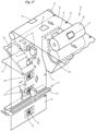
- Die Ausführung gemäß
Fig. 16 unterscheidet sich von dem vorstehenden Ausführungsbeispiel dadurch, dass die Verschlusslaschen 20 bereits in einer vorverlegten Übergabestation an der Bahn 36 angebracht werden - im Bereich der Stanzung 53, die insbesondere zuerst angebracht wird. Danach vollzieht sich der bereits beschriebene Vorgang zum Abheben des Öffnungslappens 35 und zum Umlegen dieses Lappens 35. Der Folienbahn sind auch bei dem Ausführungsbeispiel derFig. 16 Kontrollorgane (Sensoren) zugeordnet, die insbesondere das Vorhandensein und die korrekte Ausbildung der Öffnung 19 und das Vorhandensein der Verschlusslasche 20 prüfen. - Die Vorrichtung gemäß
Fig. 17 ist darauf ausgerichtet, dass der Öffnungslappen 35 entfernt wird, sodass eine allseits freie (Entnahme-)Öffnung 19 entsteht. Hierzu ist vorzugsweise im Bereich einer horizontalen Transportstrecke der Folienbahn 36 ein Stanzaggregat 65 vorgesehen, welches vorliegend aus einer Stanzwalze 66 mit Stanzmesser 67 und einer Gegenwalze 68 besteht. Das Stanzmesser 67 ist als ringsherum geschlossenes, annähernd rechteckiges Messer ausgebildet, welches eine entsprechende Öffnung 19 positionsgenau in der Bahn 36 anbringt. - Danach wird die Bahn umgelenkt. Im Bereich eines vertikalen Förderabschnitts sind Prüf- bzw. Kontrollorgane der beschriebenen Ausführung positioniert und auch eine Übertragungsstation zum Anbringen der Verschlusslasche 20 im Bereich der Öffnungen 19. Die in der Stanzstation durch das Stanzaggregat 65 entstehenden Materialstücke entsprechend der Öffnung 19 werden beseitigt, vorliegend durch einen Auffangtrichter 69, insbesondere mit Absaugwirkung.
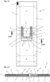
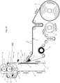
- Eine besondere Fertigungstechnologie für die Vorbereitung der Folienbahn 36 zum Herstellen von Zuschnitten der Folienpackungen ist in
Fig. 18 undFig. 19 dargestellt. Die (Dicht-)Folienbahn 36 wird vorzugsweise entlang aufrechter und quergerichteter Transportbahnen bewegt. Ein erster (aufrechter) Bahnabschnitt 70 ist für eine aufwärts gerichtete Bewegung der Bahn 36 vorgesehen. Diese wird über Umlenkwalzen 71, 72 in einen vorzugsweise horizontalen Bahnabschnitt 73 und danach zurück in einen vorzugsweise abwärts gerichteten Bahnabschnitt 74 umgelenkt. Die Verschlusslasche 20 wird vorzugsweise dem vertikalen Bahnabschnitt 70 zugeführt und auf die Folienbahn 36 packungsgerecht aufgebracht, und zwar vorzugsweise an der Bahnaußen- bzw. oberseite. Vorzugsweise im Bereich des horizontalen Bahnabschnitts 73 befindet sich ein besonderes Stanzaggregat 65 mit einer Stanzwalze 66, die vorzugsweise unterhalb der (horizontalen) Folienbahn 36 wirkt. Eine Gegenwalze 68 ist oberhalb der Bahn 36 gelagert. - Die Zuschnitte der Verschlusslaschen 20 sind vorzugsweise dicht an dicht auf einer fortlaufenden Trägerbahn 56 angeordnet. Diese wird von einer Bobine 75 abgezogen. Die Trägerbahn 56 wird einer Übertragungsstation 76 zugeführt. In deren Bereich erfolgt die Abnahme der Verschlusslaschen 20 von der Trägerbahn 56 und die präzise Übertragung an die Folienbahn 36. Die Trägerbahn 56 wird zu diesem Zweck um ein spitzwinkliges Umlenkorgan 77 herumgeführt, wodurch die klebend an der Trägerbahn 56 haftende Verschlusslasche 20 abgeschält und an die unter einem spitzen Winkel zu einem Schenkel der Trägerbahn 56 laufende Folienbahn 36 übergeben. Die Verschlusslasche 20 wird in der exakten Position durch eine Andrückwalze 78 fixiert. Der Andrückwalze 78 liegt ein Gegenorgan gegenüber, vorliegend eine Stützplatte 79.
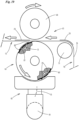
- In der nachfolgenden Stanz- bzw. Trennstation bzw. im Stanzaggregat 65 wird an der freien (unteren) Seite der Folienbahn 36 im Bereich der jeweiligen Verschlusslasche 20 eine vorzugsweise geschlossene Trennlinie angebracht, vorzugsweise durch Stanzen, die ein der Öffnung (Entnahmeöffnung 19) entsprechendes Folienstück - Öffnungslappen 35 - heraustrennt. Das Stanzaggregat 65 wird exakt gesteuert, derart, dass die Öffnung in genauer Ausrichtung auf die Verschlusslasche 20 außerhalb der Beleimung hergestellt wird, und zwar durch Trennschnitt ausschließlich im Bereich der Folienbahn 36.
- Die Stanzwalze 66 ist längs des Umfangs mit vorzugsweise mehreren, insbesondere mit zwei Stanzeinheiten versehen, also entsprechenden Gruppen von Stanzmessern 80. Diese sind vorzugsweise als geschlossener Messerrahmen ausgebildet zur Erzeugung einer geschlossenen Trennlinie in der Folienbahn 36.
- Der Öffnungslappen 35 wird durch Absaugen abgefördert. Vorzugsweise ist die Stanzwalze 66 im Bereich der Stanzmesser 80 mit Saugbohrungen 81 versehen. Diese (mehreren) Saugbohrungen liegen innerhalb des Flächenbereichs des Öffnungslappens 35, sodass dieser bei Beaufschlagung mittels Unterdruck am Umfang der Stanzwalze 66 fixiert und bei der Drehung derselben mitgenommen wird. Durch Entlüften wird der Öffnungslappen 35 freigegeben und kann entsorgt werden.
- Hierfür ist eine besondere Maßnahme vorgesehen: An der Unterseite der Stanzwalze 66 bzw. unterhalb derselben befindet sich ein Absaugaggregat 82. Die Saugbohrungen 81 der Stanzwalze 66 sind vorzugsweise so gesteuert, dass im unteren Bereich der Drehbewegung eine Umschaltung auf Druckluft stattfindet. Über die Saugbohrungen 81 wird demnach Druckluft übertragen, die zu einem Abheben des Öffnungslappens 35 und zur Übergabe an das Absaugaggregat 82 führen. Dieses übernimmt das Folienstück 35 in einem Absaugkanal 83.
- Die so vorbereitete Folienbahn wird in der beschriebenen Weise einer Trennstation zum Herstellen der Zuschnitte oder von Folienpackungen zugeführt.
- Die von den Verschlusslaschen 20 befreite Trägerbahn 56 wird zurückgeführt und von einer Sammelbobine 84 aufgenommen. Der Antrieb der Trägerbahn 56 erfolgt in diesem Bereich ohne Verschlusslaschen 20 durch eine Antriebswalze 85. Die Trägerbahn 56 wird demnach über das Umlenkorgan 77 gezogen.
- Wichtig sind Überwachungs- bzw. Kontrollorgane für korrekte Positionierung von Verschlusslasche 20 und/oder Öffnung 19 in der vorzugsweise kontinuierlich angetriebenen Folienbahn 36. Als erstes wird die positionsgenaue Übertragung der Verschlusslasche von der Trägerbahn 56 auf die Folienbahn 36 durch Sensoren (nicht gezeigt) überwacht und gesteuert, vorzugsweise in Verbindung mit Druckmarken an der Folienbahn 36. Sodann wird bei fortgesetztem (kontinuierlichen) Transport der Folienbahn 36 ein erster (optoelektronischer) Sensor 86 wirksam, vorzugsweise im Bereich des aufrechten Bahnabschnitts 17, und zwar auf der Seite der Anordnung der Verschlusslasche 20. Der Sensor 86 ist so angeordnet und wirksam, dass mindestens eine vorzugsweise quergerichtete Kante der Verschlusslasche 20 erfasst wird. Hieraus wird ein Signal für die Steuerung des Stanzaggregats 65 abgeleitet, nämlich hinsichtlich einer präzisen Anbringung der Trennlinie für die Herstellung der Öffnung 19.
- Ein weiterer Sensor 87 ist im Anschluss an das Stanzaggregat 65 wirksam, und zwar an der Innenseite der Folienbahn 36 - vorzugsweise im Bereich des abwärts gerichteten Bahnabschnitts 74 - zur Erfassung der gebildeten Ausstanzung bzw. Öffnung. Dieser Sensor 87 erfasst auch das Vorhandensein der Verschlusslasche 20 in exakter Relativstellung zur (Entnahme-)Öffnung 19. Zu diesem Zweck ist die freie Innenseite der Verschlusslasche 20 mit Markierungen und/oder Einfärbungen versehen, die eine schnelle, zuverlässige Erfassung durch den Sensor 87 gegenüber der abweichend gestalteten Folienbahn 36 gewährleisten.
Bezugszeichenliste: 10 Zigarette 49 Kragen 11 Folienblock 50 Ausnehmung 12 Zuschnitt 51 Kragensteg 13 Innen-Vorderwand 52 Schließkante 14 Innen-Rückwand 53 Stanzung 15 Innen-Seitenwand 54 Umlenkwalze 16 Innen-Bodenwand 55 Hubschiene 17 Innen-Stirnwand 56 Trägerbahn 18 Öffnungshilfe 57 Trennstation 19 Entnahmeöffnung 58 Trennmesser 20 Verschlusslasche 59 Sensor 21 Längsstreifen 60 Sensor 22 Querstreifen 61 Bedruckung 23 Verankerungsstreifen 62 Druckmarke 24 Betätigungslasche 63 Siegelorgan 25 Außenpackung 64 Siegelbacke 26 Schachtelteil 65 Stanzaggregat 27 Deckel 66 Stanzwalze 28 Schachtel-Rückwand 67 Stanzmesser 29 Deckel-Rückwand 68 Gegenwalze 30 Liniengelenk 69 Auffangtrichter 31 Deckel-Vorderwand 70 Bahnabschnitt 32 Leimstreifen 71 Umlenkwalze 33 Deckel-Innenlappen 72 Umlenkwalze 34 Tray 73 Bahnabschnitt 35 Öffnungslappen 74 Bahnabschnitt 36 Folienbahn 75 Bobine 37 Kante 76 Übertragungsstation 38 Siegelstreifen 77 Umlenkorgan 39 Anfangsschenkel 78 Andrückwalze 40 Quernaht 79 Stützplatte 41 Leimpunkt 80 Stanzmesser 42 Einzelfolie 81 Saugbohrung 43 Einzelfolie 82 Absaugaggregat 44 Leimschicht 83 Absaugkanal 45 Sperrschicht 84 Sammelbobine 46 Freizone 85 Antriebswalze 47 Schnittlinie 86 Sensor 48 Schwächungslinie 87 Sensor
Claims (5)
- Packung für Zigaretten (10) oder andere Raucherartikel mit einer Außenpackung (25), vorzugsweise in der Ausführung als Klappschachtel/Hinge-Lid-Packung mit Schachtelteil (26) und Deckel (27) sowie mit einer Innenpackung in der Ausführung als Dichtblock mit einem eine Zigarettengruppe vorzugsweise allseitig umgebenden Zuschnitt (12), wobei der Dichtblock (11) eine Öffnungshilfe (18) aufweist, vorzugsweise im stirnseitigen Bereich einer Innen-Vorderwand (13) des Dichtblocks (11) und mindestens in einem Teilbereich einer Innen-Stirnwand (17), wobei die Öffnungshilfe (18) ein vorzugsweise an der Außenseite des Dichtblocks angebrachtes Verschlussmittel, nämlich eine Verschlusslasche (20), die mittels lösbarer Verklebung am Dichtblock (11) befestigt ist und zum Öffnen des Dichtblocks (11) mindestens teilweise von diesem abgezogen wird und dadurch eine Entnahmeöffnung (19) mindestens teilweise frei legt, wobei die Verschlusslasche (20) die Entnahmeöffnung (19) in Schließstellung vollständig und allseitig überdeckt, vorzugsweise mit einem ringsherum laufenden Überdeckungsrand bzw. - streifen (21, 22, 23), wobei die Verschlusslasche (20) im Bereich der Entnahmeöffnung (19) frei von Klebemitteln ist, und wobei vorzugsweise im Bereich der Innen-Vorderwand (13) die Verschlusslasche (20) eine leimfreie Betätigungslasche (24) aufweist,
dadurch gekennzeichnet, dass der Dichtblock (11) mit einer bei der Fertigung der Packung durch ein Trennverfahren, insbesondere Stanzen oder Schneiden, hergestellten, freien Öffnung versehen ist, nämlich einer Entnahmeöffnung, und dass der leimfreie Bereich der Verschlusslasche (20) größer ist als der Bereich bzw. die Fläche der Öffnung (19) unter Bildung eines ringsherum laufenden, die Öffnung (19) umgebenden leimfreien Streifens von etwa 1,5 mm Breite, und dass die Beleimung bzw. die Leimfelder (21, 22, 23) zur Verbindung der Verschlusslasche (20) mit dem Dichtblock (11) Bereiche unterschiedlicher Intensität bzw. Stärke der Haftung aufweist. - Packung nach Anspruch 1, dadurch gekennzeichnet, dass zur Schaffung der Entnahmeöffnung (19) ein Zuschnitt (12) mit einer durch vorzugsweise Stanzung gebildeten Entnahmeöffnung (19) versehen ist, wobei ein ggf. durch die Stanzung entstehender Öffnungslappen (35) vollständig entfernt ist oder über eine (randseitige) Verbindung Teil des Zuschnitts (12) bleibt und durch Umfalten aus dem Bereich der Entnahmeöffnung (19) herausbewegt ist.
- Packung nach Anspruch 1 oder 2, dadurch gekennzeichnet, dass der mit dem Zuschnitt (12) verbundene Öffnungslappen (35) gegen eine Wandung des Dichtblocks (11) gefaltet ist, insbesondere gegen die Innenseite einer Innen-Rückwand (14), wobei der Öffnungslappen (35) in der Faltstellung fixiert ist, vorzugsweise durch thermisches Siegeln und/oder durch Klebung.
- Packung nach Anspruch 1 oder einem der weiteren Ansprüche, dadurch gekennzeichnet, dass die Beleimung bzw. die Leimfelder (21, 22, 23) an der Innenseite der Verschlusslasche (20) angebracht sind, und dass die Bereiche unterschiedlicher Intensität bzw. Stärke der Haftung derart ausgebildet sind, dass in einem Bereich des Öffnungsbeginns beim Betätigen der Verschlusslasche (20) eine Klebezone mit vergleichsweise schwächerer Klebewirkung, anschließend ein Bereich mit vergleichsweise stärkerer Klebewirkung und ein weiterer Bereich (23) ebenfalls mit höherer Klebewirkung ausgebildet ist.
- Packung nach Anspruch 1 oder einem der weiteren Ansprüche, dadurch gekennzeichnet, dass die Verschlusslasche (20) bzw. deren Betätigungslasche (24) insbesondere dauerhaft mit der Innenseite einer Deckel-Vorderwand (31) der Außenpackung (25) verbunden ist, vorzugsweise über einen Leimstreifen (32) und/oder Leimpunkte (41) an der freien Außenseite der Betätigungslasche (24).
Priority Applications (1)
| Application Number | Priority Date | Filing Date | Title |
|---|---|---|---|
| PL19158678.3T PL3508440T5 (pl) | 2015-12-10 | 2016-11-02 | Opakowanie na papierosy |
Applications Claiming Priority (4)
| Application Number | Priority Date | Filing Date | Title |
|---|---|---|---|
| DE102015016043 | 2015-12-10 | ||
| DE102016001297.8A DE102016001297A1 (de) | 2015-12-10 | 2016-02-05 | Packung für Zigaretten sowie Verfahren und Vorrichtung zum Herstellen derselben |
| EP16790524.9A EP3386886B1 (de) | 2015-12-10 | 2016-11-02 | Packung für zigaretten sowie verfahren und vorrichtung zum herstellen derselben |
| PCT/EP2016/001819 WO2017097388A1 (de) | 2015-12-10 | 2016-11-02 | Packung für zigaretten sowie verfahren und vorrichtung zum herstellen derselben |
Related Parent Applications (2)
| Application Number | Title | Priority Date | Filing Date |
|---|---|---|---|
| EP16790524.9A Division EP3386886B1 (de) | 2015-12-10 | 2016-11-02 | Packung für zigaretten sowie verfahren und vorrichtung zum herstellen derselben |
| EP16790524.9A Division-Into EP3386886B1 (de) | 2015-12-10 | 2016-11-02 | Packung für zigaretten sowie verfahren und vorrichtung zum herstellen derselben |
Publications (3)
| Publication Number | Publication Date |
|---|---|
| EP3508440A1 EP3508440A1 (de) | 2019-07-10 |
| EP3508440B1 EP3508440B1 (de) | 2021-03-31 |
| EP3508440B2 true EP3508440B2 (de) | 2024-10-30 |
Family
ID=58773297
Family Applications (2)
| Application Number | Title | Priority Date | Filing Date |
|---|---|---|---|
| EP16790524.9A Active EP3386886B1 (de) | 2015-12-10 | 2016-11-02 | Packung für zigaretten sowie verfahren und vorrichtung zum herstellen derselben |
| EP19158678.3A Active EP3508440B2 (de) | 2015-12-10 | 2016-11-02 | Packung für zigaretten |
Family Applications Before (1)
| Application Number | Title | Priority Date | Filing Date |
|---|---|---|---|
| EP16790524.9A Active EP3386886B1 (de) | 2015-12-10 | 2016-11-02 | Packung für zigaretten sowie verfahren und vorrichtung zum herstellen derselben |
Country Status (8)
| Country | Link |
|---|---|
| US (1) | US10766688B2 (de) |
| EP (2) | EP3386886B1 (de) |
| JP (1) | JP6831381B2 (de) |
| CN (1) | CN108495796B (de) |
| DE (1) | DE102016001297A1 (de) |
| PL (1) | PL3508440T5 (de) |
| RU (1) | RU2727073C2 (de) |
| WO (1) | WO2017097388A1 (de) |
Families Citing this family (13)
| Publication number | Priority date | Publication date | Assignee | Title |
|---|---|---|---|---|
| US11447320B2 (en) | 2015-12-10 | 2022-09-20 | Focke & Co. (Gmbh & Co. Kg) | Pack for cigarettes and method and apparatus for producing said pack |
| ES2744752T3 (es) * | 2017-05-18 | 2020-02-26 | Jt Int Sa | Envase para productos de consumo con solapa recerrable y método de formación de un envase para productos de consumo |
| CN107826321A (zh) * | 2017-12-01 | 2018-03-23 | 上海平臣实业有限公司 | 一种密封式内包包装设备 |
| DE102017011309A1 (de) | 2017-12-08 | 2019-06-13 | Focke & Co. (Gmbh & Co. Kg) | Verpackungsmaschine zum Herstellen von Zigarettenpackungen |
| DE102018001042A1 (de) * | 2018-02-09 | 2019-08-14 | Focke & Co. (Gmbh & Co. Kg) | Packung für Zigaretten sowie Verfahren zum Herstellen derselben |
| JP7227708B2 (ja) * | 2018-06-29 | 2023-02-22 | 小林製薬株式会社 | 包装用容器 |
| US10450120B1 (en) | 2018-11-16 | 2019-10-22 | Altria Client Services Llc | Re-seal label and container with re-seal label |
| DE202019101267U1 (de) * | 2019-03-06 | 2020-06-09 | Ccl Package Label Snc | Wiederverschluss-Etikett zum reversiblen Öffnen und Verschließen einer Öffnung eines Folienbeutels |
| DE102019106620A1 (de) * | 2019-03-15 | 2020-09-17 | Focke & Co. (Gmbh & Co. Kg) | Packung für Produkte der Zigarettenindustrie und Verfahren zur Herstellung derselben |
| DE102019106619A1 (de) * | 2019-03-15 | 2020-10-08 | Focke & Co. (Gmbh & Co. Kg) | Packung für Produkte der Zigarettenindustrie und Verfahren und Vorrichtung zur Herstellung derselben |
| CN111453126A (zh) * | 2020-05-22 | 2020-07-28 | 佛山艾仕仑科技有限公司 | 可重复使用的开口包装盒及其制备方法 |
| DE102023122260A1 (de) | 2023-08-21 | 2025-02-27 | Focke & Co. (Gmbh & Co. Kg) | Vorrichtung und Verfahren zur Herstellung von Packungen für Produkte der Zigarettenindustrie |
| DE102023125596A1 (de) * | 2023-09-18 | 2025-03-20 | Focke & Co. (Gmbh & Co. Kg) | Verfahren zum Herstellen von Packungen für Produkte der Zigarettenindustrie sowie entsprechende Packung für Produkte der Zigarettenindustrie |
Citations (6)
| Publication number | Priority date | Publication date | Assignee | Title |
|---|---|---|---|---|
| US5145091A (en) † | 1991-10-15 | 1992-09-08 | The Garber Company | Resealable container assembly |
| US5837336A (en) † | 1995-12-01 | 1998-11-17 | Tdk Corporation | Film-wrapped articles with improved opening properties |
| WO2006072750A1 (fr) † | 2005-01-07 | 2006-07-13 | Denis Guibert | Etui pour le conditionnement et la distribution de produits, notamment de granules, de lingettes, de pansements ou de poudres |
| US20110147443A1 (en) † | 2009-12-22 | 2011-06-23 | Philip Morris Usa Inc. | Wrapped container with adhesive label |
| US20140307985A1 (en) † | 2012-10-26 | 2014-10-16 | Clear Lam Packaging, Inc. | Flexible stackable package |
| WO2015114019A1 (en) † | 2014-01-31 | 2015-08-06 | Jt International S.A. | Resealable pack of smoking articles and method for packaging smoking articles |
Family Cites Families (32)
| Publication number | Priority date | Publication date | Assignee | Title |
|---|---|---|---|---|
| AU536262B2 (en) * | 1979-12-03 | 1984-05-03 | Kenji Nakamura | Resealable dispenser container |
| JPS63128936U (de) * | 1987-02-17 | 1988-08-23 | ||
| JP2603469B2 (ja) * | 1987-04-28 | 1997-04-23 | 株式会社 サト− | ラベル連続体のパンチダイ装置におけるパンチカス排出方法およびそのパンチダイ装置 |
| DE4041743A1 (de) | 1990-12-24 | 1992-06-25 | Schickedanz Ver Papierwerk | Kontinuierliches verfahren zum herstellen wiederverschliessbarer folienverpackungen |
| ITBO940293A1 (it) | 1994-06-27 | 1995-12-27 | Gd Spa | Metodo e dispositivo per l'alimentazione di assiemi colletto-coupon ad una linea di incarto di una macchina impacchettatrice per la |
| JP3468587B2 (ja) * | 1994-07-04 | 2003-11-17 | 株式会社クレシア | ウェットティッシュペーパー包装袋 |
| DE19721144B4 (de) * | 1997-05-21 | 2006-04-20 | Focke & Co.(Gmbh & Co. Kg) | Verfahren und Vorrichtung zum Handhaben von Zuschnitten |
| US5833368A (en) * | 1997-06-12 | 1998-11-10 | Kraft Foods, Inc. | Pull tab opening system for beverage container |
| DE10115936C2 (de) * | 2001-03-30 | 2003-03-20 | Reemtsma H F & Ph | Cigarettenpackung |
| DE202004000278U1 (de) | 2004-01-10 | 2004-04-22 | Dr. Schumacher Gmbh | Folienbeutel zum Verpacken von Hygiene-Feuchttüchern |
| US7717620B2 (en) | 2004-06-11 | 2010-05-18 | Sonoco Development, Inc. | Flexible packaging structure with a built-in opening and reclose feature, and method for making same |
| ITBO20050586A1 (it) | 2005-09-28 | 2005-12-28 | Gd Spa | Metodo e dispositivo per la realizzazione di un pacchetto per sigarette |
| ITBO20070456A1 (it) * | 2007-07-02 | 2007-10-01 | Gd Spa | Confezione di sigarette. |
| ITBO20070487A1 (it) | 2007-07-18 | 2007-10-17 | Gd Spa | Confezione per articoli da fumo con un incarto interno provvisto di una etichetta di chiusura. |
| DE102008035467A1 (de) * | 2008-07-30 | 2010-02-04 | Focke & Co.(Gmbh & Co. Kg) | (Zigaretten-)Packung sowie Zuschnitt, Verfahren und Vorrichtung zum Herstellen derselben |
| GB0822405D0 (en) * | 2008-12-09 | 2009-01-14 | British American Tobacco Co | A package for tobacco products |
| EP2345600A3 (de) * | 2010-01-19 | 2011-11-09 | G.D Societa' Per Azioni | Verpackung mit einer eine wiederverschliessbare Öffnung umfassend Umhullung, und entsprechende Verpackungsverfahren und Maschine |
| DE102010019867A1 (de) * | 2010-03-10 | 2011-09-15 | Focke & Co.(Gmbh & Co. Kg) | Packung für Zigaretten sowie Verfahren und Vorrichtung zur Herstellung derselben |
| ITBO20110234A1 (it) * | 2011-04-29 | 2012-10-30 | Gd Spa | Confezione di articoli da fumo con un incarto interno provvisto di una etichetta di chiusura fissata ad un coperchio incernierato. |
| DE102011119344A1 (de) * | 2011-10-11 | 2013-04-11 | Focke & Co. (Gmbh & Co. Kg) | Packung für Zigaretten sowie Verfahren zum Herstellen derselben |
| RU2622803C2 (ru) | 2012-02-15 | 2017-06-20 | Филип Моррис Продактс С.А. | Емкость с адгезивной этикеткой с областью, свободной от адгезива |
| TWI586596B (zh) | 2012-02-15 | 2017-06-11 | 菲利浦莫里斯製品股份有限公司 | 容器用強化之可再密封內包裝 |
| ITBO20120371A1 (it) * | 2012-07-10 | 2014-01-11 | Gd Spa | Metodo e unita' di lavorazione di un foglio di incarto che viene inizialmente goffrato. |
| ITBO20120391A1 (it) | 2012-07-20 | 2014-01-21 | Gd Spa | Metodo d'incarto e macchina impacchettatrice per realizzare un incarto sigillato contenente un gruppo di articoli da fumo |
| WO2014131869A1 (en) * | 2013-03-01 | 2014-09-04 | Jt International S.A. | Re-sealable tray for air and moisture sensitive products and package containing a re-sealable tray |
| DE102013009471A1 (de) | 2013-06-06 | 2014-12-11 | Focke & Co. (Gmbh & Co. Kg) | Verfahren und Vorrichtung zum Herstellen von (Zigaretten-)Packungen |
| CN203473580U (zh) * | 2013-09-10 | 2014-03-12 | 湖北淡雅香生物科技股份有限公司 | 一种新型防潮保润烟盒 |
| PL231422B1 (pl) * | 2014-03-06 | 2019-02-28 | Gd Spa | Opakowanie do wyrobów, zwłaszcza tytoniowych, arkusz zgrzewalnego, stabilizowanego materiału do pakowania oraz sposób wytwarzania arkusza zgrzewalnego, stabilizowanego materiału do pakowania |
| CN106660697B (zh) * | 2014-09-05 | 2018-11-13 | 吉第联合股份公司 | 可再闭合的香烟的包装件和相应的包装方法 |
| GB201421704D0 (en) * | 2014-12-05 | 2015-01-21 | British American Tobacco Co | A wrapper bundle of tobacco industry products |
| US10377548B2 (en) * | 2015-05-26 | 2019-08-13 | Philip Morris Products S.A. | Resealable container for consumer articles with improved moisture control |
| RU2756110C2 (ru) * | 2015-11-19 | 2021-09-28 | Саут Дакота Борд Оф Риджентс | Способ и система для производства мицеллярного казеинового концентрата с пониженным содержанием минеральных веществ |
-
2016
- 2016-02-05 DE DE102016001297.8A patent/DE102016001297A1/de not_active Withdrawn
- 2016-11-02 RU RU2018123942A patent/RU2727073C2/ru active
- 2016-11-02 WO PCT/EP2016/001819 patent/WO2017097388A1/de not_active Ceased
- 2016-11-02 CN CN201680072218.5A patent/CN108495796B/zh active Active
- 2016-11-02 US US15/777,794 patent/US10766688B2/en not_active Expired - Fee Related
- 2016-11-02 EP EP16790524.9A patent/EP3386886B1/de active Active
- 2016-11-02 EP EP19158678.3A patent/EP3508440B2/de active Active
- 2016-11-02 PL PL19158678.3T patent/PL3508440T5/pl unknown
- 2016-11-02 JP JP2018530146A patent/JP6831381B2/ja active Active
Patent Citations (6)
| Publication number | Priority date | Publication date | Assignee | Title |
|---|---|---|---|---|
| US5145091A (en) † | 1991-10-15 | 1992-09-08 | The Garber Company | Resealable container assembly |
| US5837336A (en) † | 1995-12-01 | 1998-11-17 | Tdk Corporation | Film-wrapped articles with improved opening properties |
| WO2006072750A1 (fr) † | 2005-01-07 | 2006-07-13 | Denis Guibert | Etui pour le conditionnement et la distribution de produits, notamment de granules, de lingettes, de pansements ou de poudres |
| US20110147443A1 (en) † | 2009-12-22 | 2011-06-23 | Philip Morris Usa Inc. | Wrapped container with adhesive label |
| US20140307985A1 (en) † | 2012-10-26 | 2014-10-16 | Clear Lam Packaging, Inc. | Flexible stackable package |
| WO2015114019A1 (en) † | 2014-01-31 | 2015-08-06 | Jt International S.A. | Resealable pack of smoking articles and method for packaging smoking articles |
Also Published As
| Publication number | Publication date |
|---|---|
| EP3386886A1 (de) | 2018-10-17 |
| US20180334316A1 (en) | 2018-11-22 |
| US10766688B2 (en) | 2020-09-08 |
| RU2018123942A (ru) | 2020-01-10 |
| CN108495796B (zh) | 2020-12-01 |
| JP6831381B2 (ja) | 2021-02-17 |
| RU2018123942A3 (de) | 2020-01-10 |
| EP3508440A1 (de) | 2019-07-10 |
| EP3508440B1 (de) | 2021-03-31 |
| RU2727073C2 (ru) | 2020-07-17 |
| PL3508440T5 (pl) | 2025-03-17 |
| CN108495796A (zh) | 2018-09-04 |
| WO2017097388A1 (de) | 2017-06-15 |
| PL3508440T3 (pl) | 2021-10-25 |
| JP2019501837A (ja) | 2019-01-24 |
| DE102016001297A1 (de) | 2017-06-14 |
| EP3386886B1 (de) | 2025-08-06 |
Similar Documents
| Publication | Publication Date | Title |
|---|---|---|
| EP3508440B2 (de) | Packung für zigaretten | |
| EP3494066B1 (de) | Packung für zigaretten sowie verfahren und vorrichtung zum herstellen derselben | |
| EP1341709B1 (de) | Packung, insbesondere zigarettenpackung sowie verfahren und vorrichtung zum herstellen derselben | |
| EP3378791B1 (de) | Verfahren und vorrichtung zum herstellen von zigarettenpackungen | |
| DE102011119344A1 (de) | Packung für Zigaretten sowie Verfahren zum Herstellen derselben | |
| EP2326572B1 (de) | Packung für zigaretten sowie verfahren und vorrichtung zum herstellen derselben | |
| DE102010019867A1 (de) | Packung für Zigaretten sowie Verfahren und Vorrichtung zur Herstellung derselben | |
| EP2192052A2 (de) | Beutelpackung sowie Verfahren und Vorrichtung zum Herstellen derselben | |
| DE3835721C2 (de) | ||
| DE102016003737A1 (de) | Zigarettenpackung sowie Verfahren und Vorrichtung zum Herstellen derselben | |
| EP2548819A1 (de) | Zigarettenpackung sowie Verfahren zum Herstellen derselben | |
| WO2024110268A1 (de) | Verfahren und vorrichtung zur handhabung von verpackungsmaterial sowie packung für produkte der zigarettenindustrie | |
| EP3438019B1 (de) | Zigarettenpackung und verfahren zum herstellen derselben | |
| DE102007054714A1 (de) | Vorrichtung und Verfahren zur Herstellung eines Beutels aus Papier sowie Papierbeutel | |
| EP3749590B1 (de) | Packung für zigaretten sowie verfahren zum herstellen derselben | |
| EP1077889B1 (de) | Zigarettenpackung sowie verfahren und vorrichtung zum herstellen derselben | |
| DE102019125294A1 (de) | Recyclingfähige Verpackung, insbesondere Blockbodenbeutel | |
| DE102023122260A1 (de) | Vorrichtung und Verfahren zur Herstellung von Packungen für Produkte der Zigarettenindustrie | |
| DE102023125596A1 (de) | Verfahren zum Herstellen von Packungen für Produkte der Zigarettenindustrie sowie entsprechende Packung für Produkte der Zigarettenindustrie | |
| DE202014105630U1 (de) | Verpackungsfolie sowie Vorrichtung zur Herstellung einer solchen | |
| DE102015221722A1 (de) | Klebeband, Verfahren zur Herstellung und Verfahren zur Betätigung des Klebebands | |
| EP4251527A1 (de) | Beutel, verfahren und vorrichtung zur herstellung eines beutels | |
| DE3828847A1 (de) | Vakuumpackung fuer koernige lebensmittel | |
| DE1917480A1 (de) | Taschenventil fuer Kreuzboden-Ventilsaecke aus Kunststoffolie sowie Verfahren und Vorrichtung zu seiner Herstellung |
Legal Events
| Date | Code | Title | Description |
|---|---|---|---|
| PUAI | Public reference made under article 153(3) epc to a published international application that has entered the european phase |
Free format text: ORIGINAL CODE: 0009012 |
|
| STAA | Information on the status of an ep patent application or granted ep patent |
Free format text: STATUS: THE APPLICATION HAS BEEN PUBLISHED |
|
| AC | Divisional application: reference to earlier application |
Ref document number: 3386886 Country of ref document: EP Kind code of ref document: P |
|
| AK | Designated contracting states |
Kind code of ref document: A1 Designated state(s): AL AT BE BG CH CY CZ DE DK EE ES FI FR GB GR HR HU IE IS IT LI LT LU LV MC MK MT NL NO PL PT RO RS SE SI SK SM TR |
|
| STAA | Information on the status of an ep patent application or granted ep patent |
Free format text: STATUS: REQUEST FOR EXAMINATION WAS MADE |
|
| 17P | Request for examination filed |
Effective date: 20191223 |
|
| RBV | Designated contracting states (corrected) |
Designated state(s): AL AT BE BG CH CY CZ DE DK EE ES FI FR GB GR HR HU IE IS IT LI LT LU LV MC MK MT NL NO PL PT RO RS SE SI SK SM TR |
|
| STAA | Information on the status of an ep patent application or granted ep patent |
Free format text: STATUS: EXAMINATION IS IN PROGRESS |
|
| 17Q | First examination report despatched |
Effective date: 20200612 |
|
| GRAP | Despatch of communication of intention to grant a patent |
Free format text: ORIGINAL CODE: EPIDOSNIGR1 |
|
| STAA | Information on the status of an ep patent application or granted ep patent |
Free format text: STATUS: GRANT OF PATENT IS INTENDED |
|
| INTG | Intention to grant announced |
Effective date: 20201117 |
|
| GRAS | Grant fee paid |
Free format text: ORIGINAL CODE: EPIDOSNIGR3 |
|
| GRAA | (expected) grant |
Free format text: ORIGINAL CODE: 0009210 |
|
| STAA | Information on the status of an ep patent application or granted ep patent |
Free format text: STATUS: THE PATENT HAS BEEN GRANTED |
|
| AC | Divisional application: reference to earlier application |
Ref document number: 3386886 Country of ref document: EP Kind code of ref document: P |
|
| AK | Designated contracting states |
Kind code of ref document: B1 Designated state(s): AL AT BE BG CH CY CZ DE DK EE ES FI FR GB GR HR HU IE IS IT LI LT LU LV MC MK MT NL NO PL PT RO RS SE SI SK SM TR |
|
| REG | Reference to a national code |
Ref country code: GB Ref legal event code: FG4D Free format text: NOT ENGLISH Ref country code: CH Ref legal event code: EP |
|
| REG | Reference to a national code |
Ref country code: AT Ref legal event code: REF Ref document number: 1376713 Country of ref document: AT Kind code of ref document: T Effective date: 20210415 |
|
| REG | Reference to a national code |
Ref country code: DE Ref legal event code: R096 Ref document number: 502016012730 Country of ref document: DE |
|
| REG | Reference to a national code |
Ref country code: IE Ref legal event code: FG4D Free format text: LANGUAGE OF EP DOCUMENT: GERMAN |
|
| REG | Reference to a national code |
Ref country code: RO Ref legal event code: EPE |
|
| REG | Reference to a national code |
Ref country code: LT Ref legal event code: MG9D |
|
| PG25 | Lapsed in a contracting state [announced via postgrant information from national office to epo] |
Ref country code: BG Free format text: LAPSE BECAUSE OF FAILURE TO SUBMIT A TRANSLATION OF THE DESCRIPTION OR TO PAY THE FEE WITHIN THE PRESCRIBED TIME-LIMIT Effective date: 20210630 Ref country code: HR Free format text: LAPSE BECAUSE OF FAILURE TO SUBMIT A TRANSLATION OF THE DESCRIPTION OR TO PAY THE FEE WITHIN THE PRESCRIBED TIME-LIMIT Effective date: 20210331 Ref country code: FI Free format text: LAPSE BECAUSE OF FAILURE TO SUBMIT A TRANSLATION OF THE DESCRIPTION OR TO PAY THE FEE WITHIN THE PRESCRIBED TIME-LIMIT Effective date: 20210331 Ref country code: NO Free format text: LAPSE BECAUSE OF FAILURE TO SUBMIT A TRANSLATION OF THE DESCRIPTION OR TO PAY THE FEE WITHIN THE PRESCRIBED TIME-LIMIT Effective date: 20210630 |
|
| PG25 | Lapsed in a contracting state [announced via postgrant information from national office to epo] |
Ref country code: RS Free format text: LAPSE BECAUSE OF FAILURE TO SUBMIT A TRANSLATION OF THE DESCRIPTION OR TO PAY THE FEE WITHIN THE PRESCRIBED TIME-LIMIT Effective date: 20210331 Ref country code: LV Free format text: LAPSE BECAUSE OF FAILURE TO SUBMIT A TRANSLATION OF THE DESCRIPTION OR TO PAY THE FEE WITHIN THE PRESCRIBED TIME-LIMIT Effective date: 20210331 Ref country code: SE Free format text: LAPSE BECAUSE OF FAILURE TO SUBMIT A TRANSLATION OF THE DESCRIPTION OR TO PAY THE FEE WITHIN THE PRESCRIBED TIME-LIMIT Effective date: 20210331 |
|
| REG | Reference to a national code |
Ref country code: NL Ref legal event code: MP Effective date: 20210331 |
|
| PG25 | Lapsed in a contracting state [announced via postgrant information from national office to epo] |
Ref country code: EE Free format text: LAPSE BECAUSE OF FAILURE TO SUBMIT A TRANSLATION OF THE DESCRIPTION OR TO PAY THE FEE WITHIN THE PRESCRIBED TIME-LIMIT Effective date: 20210331 Ref country code: CZ Free format text: LAPSE BECAUSE OF FAILURE TO SUBMIT A TRANSLATION OF THE DESCRIPTION OR TO PAY THE FEE WITHIN THE PRESCRIBED TIME-LIMIT Effective date: 20210331 Ref country code: LT Free format text: LAPSE BECAUSE OF FAILURE TO SUBMIT A TRANSLATION OF THE DESCRIPTION OR TO PAY THE FEE WITHIN THE PRESCRIBED TIME-LIMIT Effective date: 20210331 Ref country code: SM Free format text: LAPSE BECAUSE OF FAILURE TO SUBMIT A TRANSLATION OF THE DESCRIPTION OR TO PAY THE FEE WITHIN THE PRESCRIBED TIME-LIMIT Effective date: 20210331 Ref country code: NL Free format text: LAPSE BECAUSE OF FAILURE TO SUBMIT A TRANSLATION OF THE DESCRIPTION OR TO PAY THE FEE WITHIN THE PRESCRIBED TIME-LIMIT Effective date: 20210331 |
|
| PG25 | Lapsed in a contracting state [announced via postgrant information from national office to epo] |
Ref country code: IS Free format text: LAPSE BECAUSE OF FAILURE TO SUBMIT A TRANSLATION OF THE DESCRIPTION OR TO PAY THE FEE WITHIN THE PRESCRIBED TIME-LIMIT Effective date: 20210731 Ref country code: PT Free format text: LAPSE BECAUSE OF FAILURE TO SUBMIT A TRANSLATION OF THE DESCRIPTION OR TO PAY THE FEE WITHIN THE PRESCRIBED TIME-LIMIT Effective date: 20210802 Ref country code: SK Free format text: LAPSE BECAUSE OF FAILURE TO SUBMIT A TRANSLATION OF THE DESCRIPTION OR TO PAY THE FEE WITHIN THE PRESCRIBED TIME-LIMIT Effective date: 20210331 |
|
| REG | Reference to a national code |
Ref country code: DE Ref legal event code: R026 Ref document number: 502016012730 Country of ref document: DE |
|
| PLBI | Opposition filed |
Free format text: ORIGINAL CODE: 0009260 |
|
| PLAX | Notice of opposition and request to file observation + time limit sent |
Free format text: ORIGINAL CODE: EPIDOSNOBS2 |
|
| 26 | Opposition filed |
Opponent name: G.D S.P.A. Effective date: 20211216 |
|
| PG25 | Lapsed in a contracting state [announced via postgrant information from national office to epo] |
Ref country code: ES Free format text: LAPSE BECAUSE OF FAILURE TO SUBMIT A TRANSLATION OF THE DESCRIPTION OR TO PAY THE FEE WITHIN THE PRESCRIBED TIME-LIMIT Effective date: 20210331 Ref country code: AL Free format text: LAPSE BECAUSE OF FAILURE TO SUBMIT A TRANSLATION OF THE DESCRIPTION OR TO PAY THE FEE WITHIN THE PRESCRIBED TIME-LIMIT Effective date: 20210331 Ref country code: DK Free format text: LAPSE BECAUSE OF FAILURE TO SUBMIT A TRANSLATION OF THE DESCRIPTION OR TO PAY THE FEE WITHIN THE PRESCRIBED TIME-LIMIT Effective date: 20210331 |
|
| PLBB | Reply of patent proprietor to notice(s) of opposition received |
Free format text: ORIGINAL CODE: EPIDOSNOBS3 |
|
| PG25 | Lapsed in a contracting state [announced via postgrant information from national office to epo] |
Ref country code: IS Free format text: LAPSE BECAUSE OF FAILURE TO SUBMIT A TRANSLATION OF THE DESCRIPTION OR TO PAY THE FEE WITHIN THE PRESCRIBED TIME-LIMIT Effective date: 20210731 |
|
| PG25 | Lapsed in a contracting state [announced via postgrant information from national office to epo] |
Ref country code: MC Free format text: LAPSE BECAUSE OF FAILURE TO SUBMIT A TRANSLATION OF THE DESCRIPTION OR TO PAY THE FEE WITHIN THE PRESCRIBED TIME-LIMIT Effective date: 20210331 |
|
| REG | Reference to a national code |
Ref country code: CH Ref legal event code: PL |
|
| GBPC | Gb: european patent ceased through non-payment of renewal fee |
Effective date: 20211102 |
|
| PG25 | Lapsed in a contracting state [announced via postgrant information from national office to epo] |
Ref country code: LU Free format text: LAPSE BECAUSE OF NON-PAYMENT OF DUE FEES Effective date: 20211102 Ref country code: BE Free format text: LAPSE BECAUSE OF NON-PAYMENT OF DUE FEES Effective date: 20211130 |
|
| REG | Reference to a national code |
Ref country code: BE Ref legal event code: MM Effective date: 20211130 |
|
| PG25 | Lapsed in a contracting state [announced via postgrant information from national office to epo] |
Ref country code: LI Free format text: LAPSE BECAUSE OF NON-PAYMENT OF DUE FEES Effective date: 20211130 Ref country code: CH Free format text: LAPSE BECAUSE OF NON-PAYMENT OF DUE FEES Effective date: 20211130 |
|
| PG25 | Lapsed in a contracting state [announced via postgrant information from national office to epo] |
Ref country code: IE Free format text: LAPSE BECAUSE OF NON-PAYMENT OF DUE FEES Effective date: 20211102 Ref country code: GB Free format text: LAPSE BECAUSE OF NON-PAYMENT OF DUE FEES Effective date: 20211102 |
|
| PG25 | Lapsed in a contracting state [announced via postgrant information from national office to epo] |
Ref country code: FR Free format text: LAPSE BECAUSE OF NON-PAYMENT OF DUE FEES Effective date: 20211130 |
|
| REG | Reference to a national code |
Ref country code: AT Ref legal event code: MM01 Ref document number: 1376713 Country of ref document: AT Kind code of ref document: T Effective date: 20211102 |
|
| PG25 | Lapsed in a contracting state [announced via postgrant information from national office to epo] |
Ref country code: AT Free format text: LAPSE BECAUSE OF NON-PAYMENT OF DUE FEES Effective date: 20211102 |
|
| P01 | Opt-out of the competence of the unified patent court (upc) registered |
Effective date: 20230517 |
|
| PG25 | Lapsed in a contracting state [announced via postgrant information from national office to epo] |
Ref country code: CY Free format text: LAPSE BECAUSE OF FAILURE TO SUBMIT A TRANSLATION OF THE DESCRIPTION OR TO PAY THE FEE WITHIN THE PRESCRIBED TIME-LIMIT Effective date: 20210331 |
|
| PG25 | Lapsed in a contracting state [announced via postgrant information from national office to epo] |
Ref country code: HU Free format text: LAPSE BECAUSE OF FAILURE TO SUBMIT A TRANSLATION OF THE DESCRIPTION OR TO PAY THE FEE WITHIN THE PRESCRIBED TIME-LIMIT; INVALID AB INITIO Effective date: 20161102 Ref country code: GR Free format text: LAPSE BECAUSE OF FAILURE TO SUBMIT A TRANSLATION OF THE DESCRIPTION OR TO PAY THE FEE WITHIN THE PRESCRIBED TIME-LIMIT Effective date: 20210331 |
|
| APAH | Appeal reference modified |
Free format text: ORIGINAL CODE: EPIDOSCREFNO |
|
| APBM | Appeal reference recorded |
Free format text: ORIGINAL CODE: EPIDOSNREFNO |
|
| APBP | Date of receipt of notice of appeal recorded |
Free format text: ORIGINAL CODE: EPIDOSNNOA2O |
|
| PG25 | Lapsed in a contracting state [announced via postgrant information from national office to epo] |
Ref country code: MK Free format text: LAPSE BECAUSE OF FAILURE TO SUBMIT A TRANSLATION OF THE DESCRIPTION OR TO PAY THE FEE WITHIN THE PRESCRIBED TIME-LIMIT Effective date: 20210331 |
|
| APBU | Appeal procedure closed |
Free format text: ORIGINAL CODE: EPIDOSNNOA9O |
|
| PG25 | Lapsed in a contracting state [announced via postgrant information from national office to epo] |
Ref country code: TR Free format text: LAPSE BECAUSE OF FAILURE TO SUBMIT A TRANSLATION OF THE DESCRIPTION OR TO PAY THE FEE WITHIN THE PRESCRIBED TIME-LIMIT Effective date: 20210331 |
|
| PUAH | Patent maintained in amended form |
Free format text: ORIGINAL CODE: 0009272 |
|
| STAA | Information on the status of an ep patent application or granted ep patent |
Free format text: STATUS: PATENT MAINTAINED AS AMENDED |
|
| PG25 | Lapsed in a contracting state [announced via postgrant information from national office to epo] |
Ref country code: MT Free format text: LAPSE BECAUSE OF FAILURE TO SUBMIT A TRANSLATION OF THE DESCRIPTION OR TO PAY THE FEE WITHIN THE PRESCRIBED TIME-LIMIT Effective date: 20210331 |
|
| 27A | Patent maintained in amended form |
Effective date: 20241030 |
|
| AK | Designated contracting states |
Kind code of ref document: B2 Designated state(s): AL AT BE BG CH CY CZ DE DK EE ES FI FR GB GR HR HU IE IS IT LI LT LU LV MC MK MT NL NO PL PT RO RS SE SI SK SM TR |
|
| REG | Reference to a national code |
Ref country code: DE Ref legal event code: R102 Ref document number: 502016012730 Country of ref document: DE |
|
| PGFP | Annual fee paid to national office [announced via postgrant information from national office to epo] |
Ref country code: DE Payment date: 20251029 Year of fee payment: 10 |
|
| PGFP | Annual fee paid to national office [announced via postgrant information from national office to epo] |
Ref country code: IT Payment date: 20251128 Year of fee payment: 10 |
|
| PGFP | Annual fee paid to national office [announced via postgrant information from national office to epo] |
Ref country code: PL Payment date: 20251017 Year of fee payment: 10 |
|
| PGFP | Annual fee paid to national office [announced via postgrant information from national office to epo] |
Ref country code: RO Payment date: 20251028 Year of fee payment: 10 |