EP3502542A1 - Röhrenlampe mit leadframe - Google Patents
Röhrenlampe mit leadframe Download PDFInfo
- Publication number
- EP3502542A1 EP3502542A1 EP18152566.8A EP18152566A EP3502542A1 EP 3502542 A1 EP3502542 A1 EP 3502542A1 EP 18152566 A EP18152566 A EP 18152566A EP 3502542 A1 EP3502542 A1 EP 3502542A1
- Authority
- EP
- European Patent Office
- Prior art keywords
- leadframe
- driver
- leadframes
- illuminant according
- electronic components
- Prior art date
- Legal status (The legal status is an assumption and is not a legal conclusion. Google has not performed a legal analysis and makes no representation as to the accuracy of the status listed.)
- Granted
Links
Images



Classifications
-
- F—MECHANICAL ENGINEERING; LIGHTING; HEATING; WEAPONS; BLASTING
- F21—LIGHTING
- F21K—NON-ELECTRIC LIGHT SOURCES USING LUMINESCENCE; LIGHT SOURCES USING ELECTROCHEMILUMINESCENCE; LIGHT SOURCES USING CHARGES OF COMBUSTIBLE MATERIAL; LIGHT SOURCES USING SEMICONDUCTOR DEVICES AS LIGHT-GENERATING ELEMENTS; LIGHT SOURCES NOT OTHERWISE PROVIDED FOR
- F21K9/00—Light sources using semiconductor devices as light-generating elements, e.g. using light-emitting diodes [LED] or lasers
- F21K9/20—Light sources comprising attachment means
- F21K9/27—Retrofit light sources for lighting devices with two fittings for each light source, e.g. for substitution of fluorescent tubes
-
- F—MECHANICAL ENGINEERING; LIGHTING; HEATING; WEAPONS; BLASTING
- F21—LIGHTING
- F21K—NON-ELECTRIC LIGHT SOURCES USING LUMINESCENCE; LIGHT SOURCES USING ELECTROCHEMILUMINESCENCE; LIGHT SOURCES USING CHARGES OF COMBUSTIBLE MATERIAL; LIGHT SOURCES USING SEMICONDUCTOR DEVICES AS LIGHT-GENERATING ELEMENTS; LIGHT SOURCES NOT OTHERWISE PROVIDED FOR
- F21K9/00—Light sources using semiconductor devices as light-generating elements, e.g. using light-emitting diodes [LED] or lasers
- F21K9/20—Light sources comprising attachment means
- F21K9/23—Retrofit light sources for lighting devices with a single fitting for each light source, e.g. for substitution of incandescent lamps with bayonet or threaded fittings
- F21K9/238—Arrangement or mounting of circuit elements integrated in the light source
-
- F—MECHANICAL ENGINEERING; LIGHTING; HEATING; WEAPONS; BLASTING
- F21—LIGHTING
- F21K—NON-ELECTRIC LIGHT SOURCES USING LUMINESCENCE; LIGHT SOURCES USING ELECTROCHEMILUMINESCENCE; LIGHT SOURCES USING CHARGES OF COMBUSTIBLE MATERIAL; LIGHT SOURCES USING SEMICONDUCTOR DEVICES AS LIGHT-GENERATING ELEMENTS; LIGHT SOURCES NOT OTHERWISE PROVIDED FOR
- F21K9/00—Light sources using semiconductor devices as light-generating elements, e.g. using light-emitting diodes [LED] or lasers
- F21K9/20—Light sources comprising attachment means
- F21K9/27—Retrofit light sources for lighting devices with two fittings for each light source, e.g. for substitution of fluorescent tubes
- F21K9/278—Arrangement or mounting of circuit elements integrated in the light source
-
- F—MECHANICAL ENGINEERING; LIGHTING; HEATING; WEAPONS; BLASTING
- F21—LIGHTING
- F21K—NON-ELECTRIC LIGHT SOURCES USING LUMINESCENCE; LIGHT SOURCES USING ELECTROCHEMILUMINESCENCE; LIGHT SOURCES USING CHARGES OF COMBUSTIBLE MATERIAL; LIGHT SOURCES USING SEMICONDUCTOR DEVICES AS LIGHT-GENERATING ELEMENTS; LIGHT SOURCES NOT OTHERWISE PROVIDED FOR
- F21K9/00—Light sources using semiconductor devices as light-generating elements, e.g. using light-emitting diodes [LED] or lasers
- F21K9/90—Methods of manufacture
-
- F—MECHANICAL ENGINEERING; LIGHTING; HEATING; WEAPONS; BLASTING
- F21—LIGHTING
- F21V—FUNCTIONAL FEATURES OR DETAILS OF LIGHTING DEVICES OR SYSTEMS THEREOF; STRUCTURAL COMBINATIONS OF LIGHTING DEVICES WITH OTHER ARTICLES, NOT OTHERWISE PROVIDED FOR
- F21V19/00—Fastening of light sources or lamp holders
- F21V19/001—Fastening of light sources or lamp holders the light sources being semiconductors devices, e.g. LEDs
- F21V19/003—Fastening of light source holders, e.g. of circuit boards or substrates holding light sources
- F21V19/005—Fastening of light source holders, e.g. of circuit boards or substrates holding light sources by permanent fixing means, e.g. gluing, riveting or embedding in a potting compound
-
- F—MECHANICAL ENGINEERING; LIGHTING; HEATING; WEAPONS; BLASTING
- F21—LIGHTING
- F21V—FUNCTIONAL FEATURES OR DETAILS OF LIGHTING DEVICES OR SYSTEMS THEREOF; STRUCTURAL COMBINATIONS OF LIGHTING DEVICES WITH OTHER ARTICLES, NOT OTHERWISE PROVIDED FOR
- F21V23/00—Arrangement of electric circuit elements in or on lighting devices
- F21V23/001—Arrangement of electric circuit elements in or on lighting devices the elements being electrical wires or cables
- F21V23/002—Arrangements of cables or conductors inside a lighting device, e.g. means for guiding along parts of the housing or in a pivoting arm
-
- F—MECHANICAL ENGINEERING; LIGHTING; HEATING; WEAPONS; BLASTING
- F21—LIGHTING
- F21V—FUNCTIONAL FEATURES OR DETAILS OF LIGHTING DEVICES OR SYSTEMS THEREOF; STRUCTURAL COMBINATIONS OF LIGHTING DEVICES WITH OTHER ARTICLES, NOT OTHERWISE PROVIDED FOR
- F21V23/00—Arrangement of electric circuit elements in or on lighting devices
- F21V23/003—Arrangement of electric circuit elements in or on lighting devices the elements being electronics drivers or controllers for operating the light source, e.g. for a LED array
- F21V23/004—Arrangement of electric circuit elements in or on lighting devices the elements being electronics drivers or controllers for operating the light source, e.g. for a LED array arranged on a substrate, e.g. a printed circuit board
- F21V23/006—Arrangement of electric circuit elements in or on lighting devices the elements being electronics drivers or controllers for operating the light source, e.g. for a LED array arranged on a substrate, e.g. a printed circuit board the substrate being distinct from the light source holder
-
- F—MECHANICAL ENGINEERING; LIGHTING; HEATING; WEAPONS; BLASTING
- F21—LIGHTING
- F21V—FUNCTIONAL FEATURES OR DETAILS OF LIGHTING DEVICES OR SYSTEMS THEREOF; STRUCTURAL COMBINATIONS OF LIGHTING DEVICES WITH OTHER ARTICLES, NOT OTHERWISE PROVIDED FOR
- F21V29/00—Protecting lighting devices from thermal damage; Cooling or heating arrangements specially adapted for lighting devices or systems
- F21V29/50—Cooling arrangements
- F21V29/502—Cooling arrangements characterised by the adaptation for cooling of specific components
- F21V29/503—Cooling arrangements characterised by the adaptation for cooling of specific components of light sources
-
- H—ELECTRICITY
- H10—SEMICONDUCTOR DEVICES; ELECTRIC SOLID-STATE DEVICES NOT OTHERWISE PROVIDED FOR
- H10H—INORGANIC LIGHT-EMITTING SEMICONDUCTOR DEVICES HAVING POTENTIAL BARRIERS
- H10H20/00—Individual inorganic light-emitting semiconductor devices having potential barriers, e.g. light-emitting diodes [LED]
- H10H20/80—Constructional details
- H10H20/85—Packages
- H10H20/857—Interconnections, e.g. lead-frames, bond wires or solder balls
-
- H—ELECTRICITY
- H10—SEMICONDUCTOR DEVICES; ELECTRIC SOLID-STATE DEVICES NOT OTHERWISE PROVIDED FOR
- H10W—GENERIC PACKAGES, INTERCONNECTIONS, CONNECTORS OR OTHER CONSTRUCTIONAL DETAILS OF DEVICES COVERED BY CLASS H10
- H10W70/00—Package substrates; Interposers; Redistribution layers [RDL]
- H10W70/01—Manufacture or treatment
- H10W70/04—Manufacture or treatment of leadframes
- H10W70/042—Etching
-
- H—ELECTRICITY
- H10—SEMICONDUCTOR DEVICES; ELECTRIC SOLID-STATE DEVICES NOT OTHERWISE PROVIDED FOR
- H10W—GENERIC PACKAGES, INTERCONNECTIONS, CONNECTORS OR OTHER CONSTRUCTIONAL DETAILS OF DEVICES COVERED BY CLASS H10
- H10W70/00—Package substrates; Interposers; Redistribution layers [RDL]
- H10W70/01—Manufacture or treatment
- H10W70/04—Manufacture or treatment of leadframes
- H10W70/048—Mechanical treatments, e.g. punching, cutting, deforming or cold welding
-
- H—ELECTRICITY
- H10—SEMICONDUCTOR DEVICES; ELECTRIC SOLID-STATE DEVICES NOT OTHERWISE PROVIDED FOR
- H10W—GENERIC PACKAGES, INTERCONNECTIONS, CONNECTORS OR OTHER CONSTRUCTIONAL DETAILS OF DEVICES COVERED BY CLASS H10
- H10W90/00—Package configurations
-
- F—MECHANICAL ENGINEERING; LIGHTING; HEATING; WEAPONS; BLASTING
- F21—LIGHTING
- F21K—NON-ELECTRIC LIGHT SOURCES USING LUMINESCENCE; LIGHT SOURCES USING ELECTROCHEMILUMINESCENCE; LIGHT SOURCES USING CHARGES OF COMBUSTIBLE MATERIAL; LIGHT SOURCES USING SEMICONDUCTOR DEVICES AS LIGHT-GENERATING ELEMENTS; LIGHT SOURCES NOT OTHERWISE PROVIDED FOR
- F21K9/00—Light sources using semiconductor devices as light-generating elements, e.g. using light-emitting diodes [LED] or lasers
- F21K9/20—Light sources comprising attachment means
- F21K9/23—Retrofit light sources for lighting devices with a single fitting for each light source, e.g. for substitution of incandescent lamps with bayonet or threaded fittings
- F21K9/232—Retrofit light sources for lighting devices with a single fitting for each light source, e.g. for substitution of incandescent lamps with bayonet or threaded fittings specially adapted for generating an essentially omnidirectional light distribution, e.g. with a glass bulb
-
- F—MECHANICAL ENGINEERING; LIGHTING; HEATING; WEAPONS; BLASTING
- F21—LIGHTING
- F21V—FUNCTIONAL FEATURES OR DETAILS OF LIGHTING DEVICES OR SYSTEMS THEREOF; STRUCTURAL COMBINATIONS OF LIGHTING DEVICES WITH OTHER ARTICLES, NOT OTHERWISE PROVIDED FOR
- F21V23/00—Arrangement of electric circuit elements in or on lighting devices
- F21V23/003—Arrangement of electric circuit elements in or on lighting devices the elements being electronics drivers or controllers for operating the light source, e.g. for a LED array
- F21V23/004—Arrangement of electric circuit elements in or on lighting devices the elements being electronics drivers or controllers for operating the light source, e.g. for a LED array arranged on a substrate, e.g. a printed circuit board
- F21V23/005—Arrangement of electric circuit elements in or on lighting devices the elements being electronics drivers or controllers for operating the light source, e.g. for a LED array arranged on a substrate, e.g. a printed circuit board the substrate is supporting also the light source
-
- F—MECHANICAL ENGINEERING; LIGHTING; HEATING; WEAPONS; BLASTING
- F21—LIGHTING
- F21V—FUNCTIONAL FEATURES OR DETAILS OF LIGHTING DEVICES OR SYSTEMS THEREOF; STRUCTURAL COMBINATIONS OF LIGHTING DEVICES WITH OTHER ARTICLES, NOT OTHERWISE PROVIDED FOR
- F21V23/00—Arrangement of electric circuit elements in or on lighting devices
- F21V23/06—Arrangement of electric circuit elements in or on lighting devices the elements being coupling devices, e.g. connectors
-
- F—MECHANICAL ENGINEERING; LIGHTING; HEATING; WEAPONS; BLASTING
- F21—LIGHTING
- F21Y—INDEXING SCHEME ASSOCIATED WITH SUBCLASSES F21K, F21L, F21S and F21V, RELATING TO THE FORM OR THE KIND OF THE LIGHT SOURCES OR OF THE COLOUR OF THE LIGHT EMITTED
- F21Y2103/00—Elongate light sources, e.g. fluorescent tubes
- F21Y2103/10—Elongate light sources, e.g. fluorescent tubes comprising a linear array of point-like light-generating elements
-
- F—MECHANICAL ENGINEERING; LIGHTING; HEATING; WEAPONS; BLASTING
- F21—LIGHTING
- F21Y—INDEXING SCHEME ASSOCIATED WITH SUBCLASSES F21K, F21L, F21S and F21V, RELATING TO THE FORM OR THE KIND OF THE LIGHT SOURCES OR OF THE COLOUR OF THE LIGHT EMITTED
- F21Y2115/00—Light-generating elements of semiconductor light sources
- F21Y2115/10—Light-emitting diodes [LED]
-
- H—ELECTRICITY
- H05—ELECTRIC TECHNIQUES NOT OTHERWISE PROVIDED FOR
- H05K—PRINTED CIRCUITS; CASINGS OR CONSTRUCTIONAL DETAILS OF ELECTRIC APPARATUS; MANUFACTURE OF ASSEMBLAGES OF ELECTRICAL COMPONENTS
- H05K3/00—Apparatus or processes for manufacturing printed circuits
- H05K3/10—Apparatus or processes for manufacturing printed circuits in which conductive material is applied to the insulating support in such a manner as to form the desired conductive pattern
- H05K3/20—Apparatus or processes for manufacturing printed circuits in which conductive material is applied to the insulating support in such a manner as to form the desired conductive pattern by affixing prefabricated conductor pattern
- H05K3/202—Apparatus or processes for manufacturing printed circuits in which conductive material is applied to the insulating support in such a manner as to form the desired conductive pattern by affixing prefabricated conductor pattern using self-supporting metal foil pattern
-
- H—ELECTRICITY
- H10—SEMICONDUCTOR DEVICES; ELECTRIC SOLID-STATE DEVICES NOT OTHERWISE PROVIDED FOR
- H10H—INORGANIC LIGHT-EMITTING SEMICONDUCTOR DEVICES HAVING POTENTIAL BARRIERS
- H10H20/00—Individual inorganic light-emitting semiconductor devices having potential barriers, e.g. light-emitting diodes [LED]
- H10H20/01—Manufacture or treatment
- H10H20/036—Manufacture or treatment of packages
- H10H20/0364—Manufacture or treatment of packages of interconnections
-
- H—ELECTRICITY
- H10—SEMICONDUCTOR DEVICES; ELECTRIC SOLID-STATE DEVICES NOT OTHERWISE PROVIDED FOR
- H10H—INORGANIC LIGHT-EMITTING SEMICONDUCTOR DEVICES HAVING POTENTIAL BARRIERS
- H10H20/00—Individual inorganic light-emitting semiconductor devices having potential barriers, e.g. light-emitting diodes [LED]
- H10H20/80—Constructional details
- H10H20/85—Packages
- H10H20/858—Means for heat extraction or cooling
- H10H20/8585—Means for heat extraction or cooling being an interconnection
Definitions
- the present invention relates to a tube lamp having a lead frame based light engine, in particular a LED retrofit tube lamp, e.g. Types T5 and T8.
- Fluorescent tube lamps are increasingly being replaced by retrofit tubular lamps with semiconductor light elements (e.g., light emitting diodes, LEDs).
- retrofit tubular lamps usually have a housing in the form of a tubular bulb which is at least partially transparent (translucent or transparent), with two end caps at both ends of the tubular bulb, a light engine including a plurality of LEDs, and a electronic driver that supplies the LEDs with electrical energy with the required electrical parameters (current, voltage) to operate them.
- the term "light engine” is commonly used for the arrangement of the plurality of LEDs and a holding structure for the LEDs, which includes electrically conductive structures and / or cables, via which the LEDs can be supplied with electrical energy from the electric driver.
- LED tube lamps use a printed circuit board for the light engine, on which the LEDs are attached, for example, soldered.
- Such circuit boards are typically formed by etching a blank comprising a copper layer disposed on an electrically non-conductive substrate has produced. This ensures a high consumption of copper and accordingly high production costs and a high environmental impact.
- Wiring boards consist of strips of electrically conductive material (eg aluminum) laminated between electrically insulating, flexible layers (eg polyimide). By punching out parts of the electrically conductive strips, the desired circuit design can then be achieved. Through openings in one of the electrically insulating layers, the LEDs can be connected to the electrically conductive strips.
- an illuminant having a translucent tubular bulb, at least one end cap disposed at one end of the tubular bulb, and a light engine disposed in the tubular bulb.
- the light engine has a leadframe on which a plurality of semiconductor light-emitting elements, in particular LEDs, is arranged.
- electrically conductive structures are referred to, which are punched from a metal sheet or cut (eg by laser cutting or water jet cutting) and without electrically insulating substrate (such as circuit boards) or electrically insulating, flexible layers (such as Wiring Boards) get along.
- the strip conductors are punched out or cut out of a metal sheet, wherein transport strips and connecting webs for stabilizing the stamped sheet remain for further processing. The transport strips and connecting webs are removed at a later time, for example when the leadframe is sufficiently stabilized by electrical components mounted thereon.
- the fastening of the semiconductor light elements is effected by an SMD soldering technique (SMD stands for "surface-mount device”), in which the solder points on the punched sheet metal parts (conductors) provided with a solder paste, then fitted with the semiconductor light elements and finally heated by infrared radiation of a melting furnace which causes the solder paste to melt.
- SMD surface-mount device
- the semiconductor light elements are connected to the conductor tracks.
- the leadframe is a planar structure that has two opposite and substantially parallel surfaces at a distance from the sheet thickness.
- the leadframe may be made of a low cost material, such as steel, or a high thermal conductivity material, such as copper, or an optically high grade metal, such as brass.
- the sheet thickness is preferably in the range of 0.1 mm to 2 mm, more preferably in the range of 0.2 mm to 0.8 mm.
- materials that can be used for printed circuit boards (PCB) are suitable.
- the leadframe may be coated, for example with an Sn, Zn, Au, Ag, Pt, Pd or Ni layer, and / or the surfaces of the leadframe may be partially or completely roughened.
- the surfaces of the leadframes can also come with a well-reflective Coating, for example, be coated with a white or light paint or varnish layer (in particular solder mask).
- the production of a leadframe is thus simpler than that of a wiring board or a printed circuit board.
- the conductive structures can be chosen more flexibly than with a Wiring Board.
- the thermal conductivity of the metallic lead frame also improves the heat dissipation from the semiconductor light elements during operation.
- arranged on the leadframe means that the corresponding component is fastened to the leadframe and is in electrical connection with the leadframe.
- the arrangement of the components can take place on a surface or on both surfaces of the leadframe. Particularly in the case of semiconductor light-emitting elements, a better all-round radiation of the light can be achieved by equipping the leadframe on both sides.
- the light source has two end caps disposed at opposite ends of the tubular bulb.
- a lighting means may for example have the design T5 or T8.
- the lighting means has exactly one end cap disposed at one end of the tubular bulb.
- the other end of the tubular piston may be closed with the material of the tubular piston.
- a light source can be designed, for example, as a retrofit lamp for a compact fluorescent lamp.
- the tubular piston is gas-tight.
- the gas-tight tubular bulb is filled with a filling gas, which in particular has a gas with high thermal conductivity.
- the gas with high thermal conductivity can, for example Helium, oxygen or hydrogen or a mixture of these (eg helium / hydrogen or helium / oxygen).
- the filling gas may comprise further gaseous constituents with which, for example, high internal vessel pressures and / or optical light changes, such as light filtering and improved light outputs, are achieved.
- the fill gas may also include nitrogen, argon, air, neon, carbon dioxide, nitrogen dioxide or sulfur hexafluoride.
- the proportion of the gas with high thermal conductivity of the filling gas is 1 - 100%, preferably 50 - 90%.
- the gas pressure in the vessel is in practice between 0.01 and 1200 hPa, with a preferred gas pressure between 0.1 and 1000 hPa.
- the lighting means comprises an electronic driver having a plurality of electronic components, wherein at least one of the electronic components is disposed within the tubular piston.
- the electronic components may be disposed within the tubular piston.
- electronic components in which outgassing is to be expected during operation are preferably to be arranged outside the tubular piston. This prevents the outgassing from changing the filling gas present in the tubular piston and thus possibly its properties.
- the components of the luminous means are best protected against external influences and the luminous means can be used in environments with demanding environmental conditions, e.g. as street lighting, in greenhouses, in coastal areas with high salinity in the air, production environments with aggressive gases, etc.
- the semiconductor light-emitting elements can be selected with a correspondingly suitable spectral range.
- all the semiconductor light-emitting elements can emit light substantially in the same spectral range, or two or more different types of semiconductor light-emitting elements can be used, e.g. blue emitting and red emitting semiconductor light elements for the illumination of plants.
- At least one of the electronic components disposed within the tubular bulb is disposed on the leadframe.
- the leadframe can provide for the electrical connection of the electronic component.
- a printed circuit board, on which further electronic components of the electronic driver are arranged, can thereby be as small as possible. This further reduces possible outgassing inside the tubular plunger through the circuit board.
- the leadframe has a central region on which the plurality of semiconductor light-emitting elements is arranged, and at least one end region, on which at least one of the electronic components of the electronic driver is arranged.
- the electronic components of the electronic driver which are larger than that Semiconductor lighting elements are arranged at the ends away from the semiconductor light-emitting elements, where they hinder the emission of light through the semiconductor light elements as little as possible.
- the leadframe may have additional connecting sections which electrically connect the two end regions.
- connecting portions In order to prevent that have such connecting portions which extend over the entire length of the leadframe, undesirable electromagnetic interference emissions (electromagnetic interference, EMI) result, these connecting portions can be connected at one or more points via capacitors with adjacent portions of the leadframe.
- EMI electromagnetic interference
- the width of the leadframe in at least one end region is greater than the width of the leadframe in the middle region.
- the width of the leadframe in the central region is between about 6 mm and about 10 mm, preferably between about 7 mm and about 8 mm.
- the width of the central region can be approximately 7 mm. With additional connecting sections may reach the width of the central region up to about 10 mm.
- the width of the leadframe is variable over its length.
- the width of the leadframe may vary linearly over its length, preferably continuously linearly, for example from a first width at a first end of the leadframe to a second width that is smaller than the first width at a second end of the leadframe.
- An embodiment of the leadframe with continuously linearly varying width has the further advantage that a plurality of leadframes can be manufactured without waste from a starting material by alternately arranging a narrow and a wide end of adjacent leadframes next to one another.
- a production of multiple leadframes without waste from a starting material can also be achieved if only one of the end sections of the leadframe is wider than the middle section, preferably approximately twice as wide as the central section. Then, in manufacture, the wide end portions of the first, third, etc. leadframes can be juxtaposed on one side and the wide end portions of the second, fourth, etc. leadframes can be placed on the other side, ie the corresponding leadframes rotated through 180 ° become.
- the electronic driver is a linear driver.
- Linear drivers for LED lamps are, for example, from the international patent applications WO 2007/144365 A1 and WO 02/23956 A2 known, the disclosure of which is fully incorporated herein by reference.
- the linear drivers disclosed in these publications can also be used in embodiments of the illuminant according to the invention.
- a linear driver has the advantage that it manages with very few electronic components.
- a current regulator commonly available as an integrated circuit (IC).
- the current regulator used is a transistor or a LM317AT from National Semiconductor.
- a BP5151HC from Bright Power Semiconductor Co. may be used.
- the current regulator is arranged on the lead board, whereby the heat generated by this during operation can be dissipated well.
- the electronic driver is embedded in a filler material.
- the filler may be a polymer composition (eg casting resins and / or highly viscous adhesive of silicone, polyurethane, polyacrylic, polyester, polyamide, polyolefin and / or epoxy) and / or a filler (eg glass beads, sand, lime, ceramic powder such as Al 2 O 3 or a mixture of these).
- the polymer composition may be translucent (especially transparent).
- the embedded in the filler driver may also be provided with a sealing layer (eg polymer).
- the polymer composition may be temperature, UV, moisture and / or time-hardening.
- the thermal bonding of the electronic driver to the glass envelope can be improved.
- the heat generated by the current regulator and / or the capacitor during operation can be better dissipated to the wall of the glass bulb and to the end cap.
- potted electronic drivers are preferably one-sided, i. only in an end cap) arranged in the lamp, since the filling of the lamp closed on one side can be done by gravity.
- the electronic driver can be positioned both on the leadframe, as well as on a separate circuit board.
- the electronic driver may also be pre-potted outside the lamp to envelop the electronic components and reduce any outgassing from the electronic components and the separate FR4 circuit board.
- the pre-potted driver can also be connected to the glass bulb by means of a downstream further potting process.
- the interior of the lamp is also filled in the region of the semiconductor light elements with a translucent (in particular transparent) filling material (for example glass beads, diamond-effect glittering acrylic rhinestones, polymer granules or a mixture thereof).
- a translucent (in particular transparent) filling material for example glass beads, diamond-effect glittering acrylic rhinestones, polymer granules or a mixture thereof.
- a partial coating of the piston by such a translucent filling material can be made.
- the piston can be placed obliquely and filled with a mixture of casting resin / adhesive with optical fillers (glass beads, ceramic powder, acrylic rhinestones glitter stones with diamond effect, etc.).
- the low-viscosity casting resin-filler mixture runs on to the Semiconductor LEDs opposite side (ie on the side to which the light emission takes place) down.
- the lamp is preferably closed on one side and the electronic driver can be arranged with respect to gravity below and thus simultaneously embedded in the filler.
- the lamp may also first be filled with the low-viscosity pure cast resin / adhesive, followed by a slight hardening so that the cast resin / adhesive becomes highly viscous, and finally the optical scattering particles are filled, which stick to the high-viscosity cast resin / adhesive web.
- Adhesives which are initially in solid form, e.g. as powder or granules, are present and only become liquid when heated.
- the filling process can be carried out completely by means of solids (hotmelt granules and fillers such as glass beads, sand, lime or ceramic powder).
- hotmelt granules and fillers such as glass beads, sand, lime or ceramic powder.
- the connection with the glass bulb and / or the electronic components is carried out by subsequent heating, whereby the hot melt adhesive is melted.
- the amount of Holtmelt adhesive or polymer mass can be kept as low as possible by means of a 3-stage process: 1. Introduction of the pure fillers in the driver region of the closed-end Lamp, 2. introduction of the hot melt granules on the filler granules. 3. Melt the hotmelt sealant layer and seal the driver area.
- the sealing layer is only with the temperature-resistant Lead-frame metal, the temperature-resistant soft glass envelope and the temperature-stable filling material (glass beads, sand, etc.) in contact.
- the leadframe has one or more projections, in particular deep-drawn sections, embossments, etc.
- the protrusions may be on the underside of the leadframe, i. on the surface on which no semiconductor light elements are arranged, are located.
- the projections On top of the leadframe, i. On the surface on which the semiconductor light-emitting elements are arranged, the projections then present as depressions.
- the leadframe In the region of the projections, i. essentially around the projections on the underside of the leadframe and / or on the projections, the leadframe may be provided with an adhesive with which the leadframe is attached to the inside of the tubular bulb.
- the projections reduce the distance between the leadframe and the inner surface of the tubular piston, so that a smaller amount of adhesive is needed at these locations when bonding the leadframe to the tubular piston.
- the distance between two semiconductor light elements is usually about 17 mm.
- the distance between two recesses may correspond to the 2, 3, 4 or 5 times the distance of the semiconductor light elements, in particular about 34 mm, 51 mm, 68 mm or 85 mm. Other distances are possible.
- the projections may also be distributed unevenly along the light engine.
- the lead frame may be fastened by means of retaining clips which are fastened to the inside of the tubular piston.
- retaining clips are from the international patent application WO 2011/064305 A1 known, the disclosure of which is fully incorporated herein by reference.
- the leadframe on bent portions which can be caused by unilateral punching and bending. These can increase the cooling area for highly thermally loaded electronic components.
- the leadframe can be fixed to the inside of the tubular piston by means of laser welding.
- the leadframe is heated point by point by means of a laser through the glass of the piston at locations where the leadframe abuts the inside of the piston. The heat is transferred to the glass and this melted. This merges the leadframe with the glass.
- the material of the lead frame is chosen so that it - in addition to the required electrical conductivity and solderability - has a similar thermal expansion coefficient as the glass of the tubular piston.
- the tubular piston may be made of a standard soda-lime glass having a coefficient of thermal expansion of about 9.8 ppm / K and the lead frame of DC01 steel having a thermal expansion coefficient of about 10.5 ppm / K.
- the difference of 0.7 ppm / K corresponds to a difference in linear expansion of about 0.1 mm for a lamp having a length of 1.5 m at a temperature difference of 100 K (e.g., -20 ° C to 80 ° C).
- K e.g., -20 ° C to 80 ° C
- the electronic driver has a printed circuit board on which at least one of the electronic components is arranged.
- the electronic components of the electronic driver can thus all be arranged on the printed circuit board, all on the lead board or partly on the printed circuit board and partly on the lead board.
- the circuit board can be completely inside the tubular piston or at least partially disposed in an end cap of the bulb.
- the circuit board may be connected to the leadframe via at least one electrically conductive connection element.
- two printed circuit boards may be provided for electronic components of the electronic driver, wherein each printed circuit board may be disposed entirely within the tubular bulb or at least partially within an end cap of the bulb.
- the electronic components of the electronic driver can then be distributed to the two printed circuit boards. Accordingly, two electrically conductive connecting elements for connection between the printed circuit board and leadframe are then provided.
- a first printed circuit board is arranged completely inside the (possibly gas-tightly sealed) tubular bulb and a second printed circuit board outside the tubular bulb is arranged at least partially in an end cap of the light bulb.
- the leadframe on a bent portion which serves as a connecting element in particular one of the punched out or cut metal surfaces of the leadframe can be at least partially bent into the shape of a connecting element.
- the material used for the leadframe may have spring properties that cause the bent portion of the leadframe to press against corresponding contact surfaces on the circuit board.
- the light engine further comprises an electrically conductive means, in particular a cable, the extends from a first end of the leadframe or a printed circuit board arranged at the first end of the leadframe to a second end of the leadframe or a printed circuit board arranged at the second end of the leadframe.
- an electrical connection between the two ends of the leadframe or between sections of the electronic driver arranged at both ends can be achieved without providing a corresponding section in the leadframe therefor. This allows the leadframe to be made as narrow as possible.
- the light engine has one or more stabilizing sections of an insulating material, which are introduced locally, preferably punctiformly and / or linearly, into intermediate spaces of the leadframe in order to fasten sections of the leadframe to one another and preferably to space them apart from one another.
- “Local” in this context means, in particular, that the leadframe is not completely or largely embedded in a housing or a jacket, for example made of plastic.
- the stabilization sections are therefore distinguished by the fact that they are specifically provided at locations of the leadframe where stabilization and, if necessary, spacing is required in order to ensure the mechanical and electrical functionality of the LED module.
- the stabilization sections may in particular be provided in intermediate spaces, such as gaps, in such a way that unintentional bending and contacting of electrically insulated sections of the leadframe is prevented.
- the stabilizing sections are preferably made of polymer and / or glass and / or ceramic and / or putty and / or SMD components with insulating properties.
- SMD components with insulating properties are included: resistors with an extremely high resistance in the mega or giga ohm range, reverse-biased diodes, capacitors in DC applications or the like.
- resistors with an extremely high resistance in the mega or giga ohm range resistors with an extremely high resistance in the mega or giga ohm range, reverse-biased diodes, capacitors in DC applications or the like.
- As a favorable polymer epoxy resin adhesive has proved its thermal expansion coefficient in the same Magnitude is like any polymer housing of semiconductor light elements such as LEDs and thus caused no thermal stresses on the semiconductor light elements with changing temperature stress.
- other polymers are also suitable, such as thermoplastics, for example PC, PMMA, PBT, thermosetting plastics or elastomers, for example silicones.
- the leadframe of the light engine is stabilized particularly well, so that it is easy to handle even during assembly in the tubular piston, even after the initially still stabilizing connecting webs have been removed.
- Such stabilization may be particularly advantageous where longer portions of the leadframe run side by side without being interconnected by electronic components (such as components of the electronic driver or capacitors for reducing electromagnetic emissions).
- the two surfaces of the leadframe for the most part have no contact with material of the stabilization sections. "Usually” means that more than half, preferably more than 80%, of both surfaces (individually) are not in contact with stabilizing portions. Preferably, both surfaces (individually viewed) of the leadframe are mostly uncovered (as defined above), i. also have no contact with LEDs, SMD components, solder joints, etc. on. This in particular improves the heat dissipation via the leadframe to the gas located in the tubular bulb.
- the individual stabilization sections are preferably distinguishable, ie they do not overlap to form a structure in the order of magnitude of the leadframe. Accordingly, the extent of the individual stabilization sections preferably corresponds to only a small part of the total extent of the leadframe.
- the leadframe preferably has electrically insulating gaps, such as gaps or gap sections, which are not filled and thus completely penetrate the leadframe in the thickness direction.
- the extent of the stabilization sections preferably corresponds substantially to the order of magnitude of the gaps to be bridged.
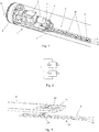
- FIG. 1 an embodiment of a tube lamp according to the invention is partially shown.
- the tube lamp has a translucent tubular bulb 1, at both ends of which an end cap 2 is arranged.
- an end cap 2 is arranged in the end cap two pins 3 are fixed, with which the tube lamp is held in an appropriate version and over which the tube lamp can be supplied with electrical energy.
- an electronic driver 4 Inside the end cap 2 and extending from there into the interior of the tubular piston 1 is an electronic driver 4, whose electronic components 5 are arranged on a printed circuit board 6.
- the driver 4 is held securely by means of a glued on the inside of the tubular piston 1 retaining rail 7 inside the tube lamp.
- a leadframe 8 is used, on which a plurality of light-emitting diodes (LEDs) 9 are arranged.
- the leadframe 8 comprises a plurality of sections 10 punched or cut out of a sheet of metal (e.g., DC01 steel).
- the leadframe 8 has substantially three parallel tracks, with the first track 11 (shown in the figure as the rear track) and the second track 12 (shown as the middle track in the figure) each composed of a plurality of sections 10 ,
- the third track 13 (shown in the figure as the front track), however, is continuous over the length of the leadframe 8.
- the terms "front”, “middle” and “rear” here refers to the illustration in the figure and are used in the following synonymous with “first”, “second” and “third” web.
- the sections 10 of the rear track 11 and the middle track 12 are offset from one another, so that they each overlap over a half section 10.
- two LEDs 9 are connected in parallel. Between the right portion (in the figure) of a portion 10 of the rear panel 11 and the left portion (in the illustration) of a portion 10 of the middle panel 12, two LEDs 9 are connected in parallel. Between the right portion (in the figure) of a portion 10 of the middle panel 12 and the left portion (in the illustration) of a portion 10 of the rear panel 11, two LEDs 9 are also connected in parallel, so that the former group of parallel LEDs and the second group of parallel LEDs are connected in series. This pattern continues over the length of the leadframe 8.
- the first (left) portion of the rear panel 11 is connected to a first output terminal of the electronic driver 4.
- the last pair with two parallel LEDs 9 ' (in FIG. 1 not shown, but in FIG. 4 seen) is connected to the right portion of the middle panel 12 and to the front (continuous) panel 13.
- a 0 ohm resistor or other conductive element may also be used for the connection between the middle track 12 and the front track 13.
- one or more connecting webs can be retained for closing the circuit, ie when the individual sections of the leadframe are disconnected, these connecting webs are not severed.
- the LEDs are arranged as a series circuit of parallel pairs of LEDs, as shown schematically in FIG. 2 is shown.
- FIG. 3 an embodiment of the connection between the circuit board of the electronic driver 4 and the leadframe 8 is shown.
- Two contact clips 26 are plugged onto the printed circuit board 6 of the driver 4, each with a substantially U-shaped contact region 14, so that the U-shaped contact regions 14 make contact with correspondingly arranged contact points on the printed circuit board 6, which represent the two output connections of the driver 4.
- an electrical connection between the printed circuit board of the electronic driver 4 and the leadframe 8 is produced.
- the left end (in the figure) of the front panel 13 and the first (left) portion of the rear panel 11 are bent to form two substantially U-shaped contact areas 14 into which the circuit board 6 of the driver 4 is inserted becomes.
- the U-shaped contact areas 14 then contact on the circuit board 6 correspondingly arranged contact points, which represent the two output terminals of the driver 4.
- the corresponding sections 10 of the leadframe 8 assume the function of the contact clips 26.
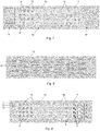
- FIG. 4 schematically is an arrangement of a plurality of lead frames 8, as in an embodiment of a light source according to FIG. 1 or in other embodiments may be used during manufacture.
- the leadframes 8 were punched or cut out of a metal sheet 15 (eg by means of laser cutting) and are still connected via connecting webs 16 to a frame 17 and to one another.
- a metal sheet 15 eg by means of laser cutting
- FIG. 4 four leadframes 8 are shown, it but also a different number of lead frames 8 can be made from a sheet 15.
- Each leadframe 8 has three tracks, an upper track 11 (corresponding to the first track or the rear track in FIG. 1 ), a middle track 12 (corresponding to the second track or middle track in FIG. 1 ) and a lower panel 13 (corresponding to the third panel or front panel in FIG. 1 ).
- the terms “upper”, “middle” and “lower” refer to the illustration in the figure and are used in the following synonymous with “first”, “second” and “third” web.
- the upper web 11 and the middle web 12 each consist of several sections 10 together.
- the lower track 13 is continuous throughout the length of the leadframe.
- the sections 10 of the upper web 11 and the middle web 12 are arranged offset to one another, so that they each overlap over a half section 10.
- two LEDs 9 are connected in parallel.
- two LEDs 9 are also connected in parallel, so that the former group of parallel LEDs and the second group of parallel LEDs are connected in series. This pattern continues over the length of the leadframe 8. For clarity, not all LEDs 9 are shown.
- the last pair with two parallel LEDs 9 ' is connected to the right portion of the middle panel 12 and to the lower (continuous) panel 13.
- a 0 ohm resistor or other conductive element may also be used for the connection between the middle track 12 and the lower track 13.
- these connecting webs 16 are not severed.
- stabilizing sections can be provided between the sections 10 and / or between the tracks 11, 12, 13 of the leadframe 8.
- the continuous lower web 13 is connected to the adjacent central web 12 locally by stabilizing sections (insulating material or insulating SMD components).
- the connecting webs 8 can be severed and the leadframes 8 are separated from the frame 17 and with each other.
- the width of the leadframes 8 is preferably about 7 mm. This means that sufficient space is available on the leadframe 8 for the LEDs 9 without unnecessarily requiring material for the leadframe 8.
- the width of the upper web 11 and the middle web 12 is preferably about (2.0 ⁇ 0.1) mm.
- the width of the lower web 13 is preferably about (1.6 ⁇ 0.1) mm.
- the width of the punch openings between the webs is preferably (0.7 ⁇ 0.1) mm.
- the width of the punch openings between the sections 10 in a web is preferably (1.0 ⁇ 0.1) mm.
- the length of the portions 10 of the upper web 11 and the middle web 12 is preferably about (67.6 ⁇ 0.5) mm.
- the length of the leadframe 8 is preferably 17 sections 10, ie about 1166 mm. This leaves room for an electronic driver for a lamp with a total length of 1200 mm (also called 4-foot lamp). If a punch that is shorter than the leadframe is to be used multiple times, the leadframe may be initially made with a length of 18 sections and a section later removed. In the figure, for better visibility, fewer sections are shown. The The above dimensions can also be used with the following leadframes.
- the first (left in the figure) portion of the upper track 11 has a length which corresponds to 3/4 of the length of the other sections 10.
- the last (right in the figure) portion of the upper track 11 also has a length which corresponds to 3/4 of the length of the other sections 10.
- the first (left in the figure) portion of the central path 12 has a length which corresponds to 1/4 of the length of the other sections 10. Accordingly, the last (in the figure right) portion of the central path 12 also has a length which corresponds to 1/4 of the length of the other sections 10.
- first (in the figure on the left) and / or last (in the figure on the right) sections can also be executed longer, which can simplify the connection to the driver, especially if end sections of the leadframe are converted to contact areas (see FIG. 3 ).
- FIG. 5 schematically an arrangement of a plurality of leadframes 8 is shown in a further embodiment during manufacture.
- Each leadframe 8 has a central region 18 and an end region 19.
- the middle area 18 of the leadframes 8 in FIG. 5 corresponds to the in FIG. 4 shown leadframes and will not be explained again here. But there are others too Embodiments of the lead frame in the central area 18 are used.
- the end region 19 of the leadframes 8 is provided for electronic components 5 of the driver 4.
- the exact division of the end portion 19 in leadframe sections depends on the design of the driver 4 and is therefore not shown here in detail.
- the width of the leadframes 8 is preferably about 7 mm. This means that sufficient space is available on the leadframe 8 for the LEDs 9 and the electronic components 5 of the driver without unnecessarily requiring material for the leadframe 8.
- FIG. 6 schematically an arrangement of a plurality of leadframes 8 is shown in a further embodiment during manufacture.
- Each leadframe 8 has a central region 18 and two end regions 19, 20.
- the end regions 19, 20 of the leadframes 8 are provided for electronic components 5 of the driver 4.
- the exact division of the end regions 19, 20 in leadframe sections depends on the design of the driver 4 and is therefore not shown here in detail.
- An embodiment of the division of the end region of the leadframe 8 is shown by way of example in FIGS FIGS. 17 to 20 shown.
- the division of the driver 4 on two end regions 19, 20 makes it possible to make the end regions 19, 20 smaller in each case and thus to distribute the non-luminous region to the two ends of the luminous means.
- the middle area 18 of the leadframes 8 in FIG. 6 is essentially the same as in FIG. 4 shown leadframes and is not explained here so far. However, other designs of the leadframe in the central region 18 can also be used.
- the leadframe In addition to that FIG. 4 assumed portion of the leadframe 8 (ie, the three upper tracks 11, 12, 13), the leadframe has two further tracks 21st on, which serve to connect the two parts of the electronic driver 4.
- the webs 21 are connected to each other and / or to the adjacent lower web 13 locally by stabilizing sections (insulating material or insulating SMD components).
- a stabilization can be effected in particular by capacitors, which can prevent or at least reduce unwanted electromagnetic emissions.
- the width of the leadframes 8 is preferably about 10 mm. This means that sufficient space is available on the leadframe 8 for the LEDs 9 and the electronic components 5 of the driver without unnecessarily requiring material for the leadframe 8.
- the additional tracks 21 require a wider version of the leadframe 8 in comparison to the previous embodiments.
- FIG. 7 schematically an arrangement of a plurality of leadframes 8 is shown in a further embodiment during manufacture.
- Each leadframe 8 has a central region 18 and an end region 19.
- the end region 19 of the leadframes 8 is provided for electronic components 5 of the driver 4.
- the exact division of the end portion 19 in leadframe sections depends on the design of the driver 4 and is therefore not shown here in detail.
- the end region 19 is twice as wide as the middle region 18, so that more space is available for the electronic components 5 of the driver 4 in the end region 19.
- the width of the central region 18 of the leadframes 8 is preferably about 7 mm, the width of the end region thus about 14 mm. This means that sufficient space is available on the leadframe 8 for the LEDs 9 and the electronic components 5 of the driver without unnecessarily requiring material for the leadframe 8.
- FIG. 8 schematically an arrangement of a plurality of leadframes 8 is shown in a further embodiment during manufacture.
- the width of the leadframes 8 decreases from a first width at a first end of the leadframe 8 to a second width that is less than the first width at a second end of the leadframe 8.
- the width at the second end is preferably no more than about 7 mm, more preferably not more than about 5 mm.
- the width at the first end is preferably about 20 mm.
- FIG. 9 schematically an arrangement of a plurality of leadframes 8 is shown in a further embodiment during manufacture.
- the arrangement of the tracks 11, 12, 13 and sections 10 of the leadframe 8 essentially corresponds to that of FIG FIG. 4 .
- electronic components 5 of the driver 4 are arranged in the region of the light engine, utilizing the division of the two upper webs 11, 12 into sections 10.
- a linear driver can be used, as shown schematically in FIG. 10 is shown.
- the electronic driver has a rectifier of four diodes D, at whose output a smoothing capacitor C1 is provided. One terminal of the smoothing capacitor C1 is connected to ground.
- an integrated circuit IC type BP5151HC is used for the linear driver.
- the connection CS of the integrated Circuit IC is connected to ground via a resistor R1.
- the terminal VD of the integrated circuit IC is connected via a capacitor C2 to ground.
- the terminal VD of the integrated circuit IC is further connected via a resistor R2 to the cathode end of the series-connected LEDs.
- the drain terminal of the integrated circuit IC is connected directly to the cathode end of the series-connected LEDs.
- the terminal GND of the integrated circuit IC is connected to ground.
- the integrated circuit IC type BP5151HC is usually available in the design ESOP8, as well as in FIG. 10 shown.
- the four NC ports have no function. If the integrated circuit with the same functionality in the SOT223 or TO252 type is used, it can be used as in FIG. 9 shown, arranged together with the resistors R1 and R2 and the capacitor C2 directly in the area of the light engine on the leadframe.
- the rectifier and the smoothing capacitor C1 can then be arranged in one or two end portions of the leadframe or on a separate circuit board.
- FIG. 11 schematically an arrangement of a plurality of leadframes 8 is shown in a further embodiment during manufacture.
- the leadframes 8 essentially correspond to the leadframes FIG. 4 .
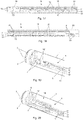
- FIG. 12 schematically shows a side view of a lead frame 8 with recesses 22 (again without LEDs) in a tubular piston 1.
- the recesses 22 and the resulting therefrom on the other side of the lead frame 8 projections serve to the distance between the leadframe 8 and the inside of the curved tubular piston 1 to reduce. This creates a narrow adhesive gap, which reduces the amount of adhesive to be used.
- FIG. 13 schematically a leadframe 8 is shown in a further embodiment.
- the leadframe 8 essentially corresponds to the leadframes FIG. 4 However, it does not have a lower track 13.
- the electrical connection between the (in the figure) right end of the leadframe 8 and a driver (not shown) on the (in the figure) left end of the leadframe can for example be done with a (schematically indicated) cable 23.
- FIG. 14 schematically an arrangement of a plurality of leadframes 8 is shown in a further embodiment during manufacture.
- the leadframes 8 essentially correspond to the leadframes FIG. 4 .
- the three tracks 11, 12, 13 of the leadframes 8 are connected to each other by stabilizing sections 24 of insulating material, whereby the stability of the leadframes 8 is increased.
- stabilizing section 24 In addition to the arrangement of the stabilizing section 24 shown, other arrangements can also be used. For reasons of clarity, not all stabilization sections 24 are shown
- FIG. 15 schematically an arrangement of a plurality of leadframes 8 is shown in a further embodiment during manufacture.
- Each leadframe 8 has two tracks, an upper track 11 and a lower track 12.
- the terms “upper” and “lower” refer to the illustration in the figure and are hereinafter synonymous with “first” and “second” track used.
- the upper web 11 and the lower web 12 each consist of several sections 10 together.
- the sections 10 of the upper track 11 and the lower track 12 are offset from each other so that they each overlap over a half section 10.
- an LED is connected between the right area (in the Figure) of a portion 10 of the upper panel 11 and the left portion (in the illustration) of a portion 10 of the lower panel 12.
- an LED is connected between the right portion (in the figure) of a portion 10 of the lower panel 12 and the left portion (in the illustration) of a portion 10 of the upper panel 11 .
- LED 9 is also connected to the LED 9, so that the LEDs are connected in series. This pattern continues over the length of the leadframe 8. For clarity, not all LEDs 9 are shown.
- the leadframe 8 thus effects a series connection of all LEDs 9 here. A continuous track for returning the electrical connection is not provided.
- FIG. 16 an embodiment of a luminous means is partially shown, in which the In FIG. 15 shown leadframe 8 is used.
- the lead frame 8 is mounted on the inside of a tubular piston 1 so as to extend from an open end of the piston 1 to a closed end of the piston 1, along the end face 25, and then from the closed end of the piston 1 back to the open end of the piston 1 runs. Since both ends of the leadframe 8 thus lie at the open end of the piston 1, they can be connected there to an electronic driver (not shown) without requiring a continuous path for returning the electrical connection.
- the other leadframes shown above can each be used without a continuous third path in such a light source.
- the in the FIGS. 9 to 15 leadframes shown 8 may each be provided with one or two end portions 19, 20 for electronic components 5 of a driver 4, as shown in the FIGS. 5 to 8 is shown.
- FIGS. 17 to 20 is exemplified as the end region or the end regions 19, 20 of a leadframe 8 can be divided into sections 10 'so that the electronic components 5 of the driver 4 can be arranged directly on the leadframe 8.
- FIG. 17 1 shows diagrammatically a first end region 19 of the leadframe 8 in the illustration on the right.
- the middle region 18 of the leadframe is shown with three webs 11, 12, 13 (in the figure below) of the light engine, each consisting of several sections 10.
- FIG. 18 1 shows schematically a second end region 20 of the leadframe 8 on the right in the illustration. On the left in the illustration, the middle region 18 of the leadframe is shown with three webs 11, 12, 13 (in the figure below) of the light engine.
- the two upper continuous tracks 21 serve to connect the two driver sections, whose components 5 are arranged in the two end regions 19, 20 of the leadframe 8.
- the sections 10, 10 'of the leadframe 8 are in the FIGS. 17 and 18 still connected to each other with connecting webs 16. These can be severed after the electronic components 5 of the driver 4 are mounted on the leadframe 8.
- FIG. 19 schematically a light source is shown in fragmentary form with a leadframe 8 on which the electronic components 5 of the driver 4 are arranged directly.
- FIG. 20 shows FIG. 20 how the leadframe 8 can be held in the end region 19 in a retaining rail 7.
- the connecting webs 16 are shown, which connect the sections 10, 10 'of the leadframe 8 during manufacture.
- a number may include exactly the specified number as well as a usual tolerance range, as long as this is not explicitly excluded.
Landscapes
- Engineering & Computer Science (AREA)
- General Engineering & Computer Science (AREA)
- Microelectronics & Electronic Packaging (AREA)
- Physics & Mathematics (AREA)
- Optics & Photonics (AREA)
- Manufacturing & Machinery (AREA)
- Led Device Packages (AREA)
- Fastening Of Light Sources Or Lamp Holders (AREA)
- Non-Portable Lighting Devices Or Systems Thereof (AREA)
Abstract
Description
- Die vorliegende Anmeldung beansprucht die Priorität der
DE 10 2017 131 063.0 , angemeldet am 22.12.2017, deren Offenbarung durch Bezugnahme vollständig hierin aufgenommen ist. - Die vorliegende Erfindung betrifft eine Röhrenlampe mit einer auf einem Leadframe basierenden Light Engine, insbesondere eine LED-Retrofit-Röhrenlampe, z.B. der Bauformen T5 und T8.
- Leuchtstoff-Röhrenlampen werden mehr und mehr durch Retrofit-Röhrenlampen mit Halbleiterleuchtelementen (z.B. Leuchtdioden, LEDs) ersetzt. Derartige Retrofit-Röhrenlampen weisen für gewöhnlich ein Gehäuse in Form eines röhrenförmigen Kolbens, der zumindest teilweise lichtdurchlässig (transluzent oder transparent) ist, mit zwei Endkappen an den beiden Enden des röhrenförmigen Kolbens, eine Light Engine, die eine Mehrzahl von LEDs beinhaltet, und einen elektronischen Treiber, der die LEDs mit elektrischer Energie mit den erforderlichen elektrischen Parametern (Strom, Spannung) zu deren Betrieb versorgt, auf.
- Der Begriff "Light Engine" wird üblicherweise verwendet für die Anordnung aus der Mehrzahl der LEDs und einer Haltestruktur für die LEDs, welche elektrisch leitfähige Strukturen und/oder Kabel beinhaltet, über die die LEDs mit elektrischer Energie vom elektrischen Treiber versorgt werden können.
- Viele Retrofit-LED-Röhrenlampen verwenden für die Light Engine eine Leiterplatte, auf der die LEDs befestigt, beispielsweise aufgelötet, sind. Solche Leiterplattenwerden üblicherweise durch Ätzen eines Rohlings, der eine auf einem elektrisch nicht-leitenden Substrat angeordnete Kupferschicht aufweist, hergestellt. Dies sorgt für einen großen Verbrauch an Kupfer und entsprechend für hohe Herstellungskosten und eine starke Umweltbelastung.
- Aus der deutschen Patentanmeldung
DE 10 2017 109 853.4 , deren Offenbarung durch Bezugnahme vollständig hierin aufgenommen ist, ist bekannt, die Light Engine einer Retrofit-Röhrenlampe auf einem sogenannten Wiring Board aufzubauen. Wiring Boards bestehen aus Streifen eines elektrisch leitenden Materials (z.B. Aluminium), das zwischen elektrisch isolierenden, flexiblen Schichten (z.B. Polyimid) laminiert ist. Durch Ausstanzen von Teilen der elektrisch leitenden Streifen kann dann das gewünschte Schaltungsdesign erzielt werden. Durch Öffnungen in einer der elektrisch isolierenden Schichten können die LEDs mit den elektrisch leitenden Streifen verbunden werden. - Auch die Herstellung von Wiring Boards ist bei allen Vorteilen gegenüber Leiterplatten aufwändig und teuer.
- Ausgehend von dem bekannten Stand der Technik ist es eine Aufgabe der vorliegenden Erfindung, ein Leuchtmittel mit einer vereinfachten Light Engine bereitzustellen.
- Die Aufgabe wird durch eine Leuchtvorrichtung mit den Merkmalen des unabhängigen Anspruchs gelöst. Vorteilhafte Weiterbildungen ergeben sich aus den Unteransprüchen.
- Entsprechend wird ein Leuchtmittel mit einem lichtdurchlässigen röhrenförmigen Kolben, mindestens einer an einem Ende des röhrenförmigen Kolbens angeordneten Endkappe und einer im röhrenförmigen Kolben angeordneten Light Engine vorgeschlagen. Erfindungsgemäß weist die Light Engine einen Leadframe auf, auf dem eine Mehrzahl von Halbleiterleuchtelementen, insbesondere LEDs, angeordnet ist.
- Als Leadframes werden hier elektrisch leitende Strukturen bezeichnet, die aus einem Metallblech gestanzt oder geschnitten (z.B. mittels Laserschneiden oder Wasserstrahlschneiden) werden und ohne elektrisch isolierendes Substrat (wie Leiterplatten) oder elektrisch isolierende, flexiblen Schichten (wie Wiring Boards) auskommen. Zur Herstellung eines Leadframes werden die Leiterbahnen aus einem Blech ausgestanzt oder ausgeschnitten, wobei Transportstreifen und Verbindungsstege zur Stabilisierung des gestanzten Blechs für die Weiterverarbeitung verbleiben. Die Transportstreifen und Verbindungsstege werden zu einem späteren Zeitpunkt entfernt, z.B. wenn der Leadframe durch darauf befestigte elektrische Komponenten ausreichend stabilisiert ist.
- Die Befestigung der Halbleiterleuchtelemente erfolgt durch eine SMD-Löttechnik (SMD steht für "Surface-mount device"), bei der die Lötpunkte auf den ausgestanzten Blechteilen (Leiterbahnen) mit einer Lötpaste versehen, anschließend mit den Halbleiterleuchtelementen bestückt und schließlich durch Infrarotstrahlung eines Schmelzofens erhitzt werden, wodurch die Lötpaste schmilzt. Auf diese Weise werden die Halbleiterleuchtelemente mit den Leiterbahnen verbunden.
- Der Leadframe ist ein flächiges Gebilde, das zwei gegenüberliegende und im Wesentlichen parallel verlaufende Oberflächen im Abstand der Blechdicke aufweist. Der Leadframe kann beispielsweise aus einem kostengünstigen Material, wie etwa Stahl, oder einem Material mit hoher Wärmeleitfähigkeit, wie etwa Kupfer, oder einem optisch hochwertig erscheinenden Metall, wie etwa Messing, gefertigt sein. Die Blechdicke liegt vorzugsweise im Bereich von 0,1 mm bis 2 mm, noch bevorzugter im Bereich von 0,2 mm bis 0,8 mm. Insbesondere kommen Materialien in Frage, die für gedruckte Platinen (PCB) anwendbar sind. Zudem kann der Leadframe beschichtet sein, beispielsweise mit einer Sn-, Zn-, Au-, Ag-, Pt-, Pd- oder Ni-Schicht, und/oder die Oberflächen des Leadframes können teilweise oder vollständig aufgeraut sein. Die Oberflächen des Leadframes können auch mit einer gut reflektierenden Beschichtung, z.B. mit einer weißen oder hellen Farb- oder Lackschicht (insbesondere Lötstopplack) beschichtet sein.
- Die Herstellung eines Leadframes ist somit einfacher als die eines Wiring Boards oder einer Leiterplatte. Auch können die leitenden Strukturen flexibler gewählt werden, als bei einem Wiring Board. Durch die Wärmeleitfähigkeit des metallischen Leadframes wird auch die Wärmeabfuhr von den Halbleiterleuchtelementen während des Betriebs verbessert.
- Im Rahmen der vorliegenden Offenbarung bedeutet "auf dem Leadframe angeordnet", dass die entsprechende Komponente am Leadframe befestigt ist und in elektrischer Verbindung mit dem Leadframe steht.
- Die Anordnung der Komponenten kann auf einer Oberfläche oder auf beiden Oberflächen des Leadframes erfolgen. Insbesondere bei den Halbleiterleuchtelementen kann durch eine beidseitige Bestückung des Leadframes eine bessere Rundumabstrahlung des Lichts erreicht werden.
- In einer Ausführungsform weist das Leuchtmittel zwei Endkappen auf, die an gegenüberliegenden Enden des röhrenförmigen Kolbens angeordnet sind. Ein solches Leuchtmittel kann beispielsweise die Bauform T5 oder T8 aufweisen.
- In einer Ausführungsform weist das Leuchtmittel genau eine Endkappe auf, die an einem Ende des röhrenförmigen Kolbens angeordnet ist. Das andere Ende des röhrenförmigen Kolbens kann mit dem Material des röhrenförmigen Kolbens verschlossen sein. Ein solches Leuchtmittel kann beispielsweise als Retrofit-Lampe für eine Kompaktleuchtstofflampe ausgestaltet sein.
- In einer Ausführungsform ist der röhrenförmige Kolben gasdicht verschlossen. Vorzugsweise ist der gasdichte röhrenförmige Kolben mit einem Füllgas gefüllt, das insbesondere ein Gas mit hoher Wärmeleitfähigkeit aufweist. Das Gas mit hoher Wärmeleitfähigkeit kann beispielsweise Helium, Sauerstoff oder Wasserstoff oder eine Mischung aus diesen (z.B. Helium/Wasserstoff oder Helium/Sauerstoff) sein. Durch eine Füllung des röhrenförmigen Kolbens mit einem Gas mit hoher Wärmeleitfähigkeit kann die Abfuhr von Wärme von den Halbleiterleuchtelementen während des Betriebs weiter verbessert werden.
- Das Füllgas kann weitere gasförmige Bestandteile aufweisen, mit denen beispielsweise hohe Gefäßinnendrucke und/oder optische Lichtveränderungen, wie Lichtfilterungen und verbesserte Lichtleistungen erreicht werden. Beispielsweise kann das Füllgas auch Stickstoff, Argon, Luft, Neon, Kohlendioxid, Stickstoffdioxid oder Schwefelhexafluorid aufweisen.
- Vorteilhafter Weise beträgt der Anteil des Gases mit hoher Wärmeleitfähigkeit am Füllgas 1 - 100%, bevorzugt 50 - 90%.
- Der Gasdruck im Gefäß beträgt in der Praxis zwischen 0,01 und 1200 hPa, wobei ein bevorzugter Gasdruck zwischen 0,1 und 1000 hPa liegt.
- In einer Ausführungsform weist das Leuchtmittel einen elektronischen Treiber mit mehreren elektronischen Bauteilen auf, wobei mindestens eines der elektronischen Bauteile innerhalb des röhrenförmigen Kolbens angeordnet ist. Es können eines, mehrere oder alle elektronischen Bauteile innerhalb des röhrenförmigen Kolbens angeordnet sein. Vorzugsweise sind insbesondere elektronische Bauteile, bei denen eine Ausgasung während des Betriebs zu erwarten ist, außerhalb des röhrenförmigen Kolbens angeordnet sein. Damit wird verhindert, dass die Ausgasungen das im röhrenförmigen Kolben vorhandene Füllgas und damit möglicherweise dessen Eigenschaften verändern.
- Es ist ein weiterer Vorteil der Verwendung eines Leadframes als Träger für die Halbleiterleuchtelemente, dass dadurch Ausgasungen durch den Träger (in bekannten Leuchtmitteln z.B. durch die Leiterplatte oder das Wiring Board) weitestgehend reduziert werden.
- Es ist von Vorteil, möglichst viele elektrische Bauteile des elektronischen Treibers innerhalb des vorzugsweise gasdichten röhrenförmigen Kolbens anzuordnen. Dadurch werden die Komponenten des Leuchtmittels bestmöglich vor äußeren Einflüssen geschützt und das Leuchtmittel kann in Umgebungen mit anspruchsvollen Umweltbedingungen zum Einsatz kommen, z.B. als Straßenbeleuchtung, in Gewächshäusern, in Küstenregionen mit hohem Salzgehalt in der Luft, Produktionsumgebungen mit aggressiven Gasen, usw.
- Je nach Einsatzumgebung können die Halbleiterleuchtelemente mit einem entsprechend geeigneten Spektralbereich gewählt werden. Dabei können alle Halbleiterleuchtelemente im Wesentlichen im gleichen Spektralbereich Licht emittieren oder es können zwei oder mehr verschiedene Typen von Halbleiterleuchtelementen zum Einsatz kommen, z.B. blau emittierende und rot emittierende Halbleiterleuchtelemente für die Beleuchtung von Pflanzen.
- In einer Ausführungsform ist mindestens eines der innerhalb des röhrenförmigen Kolbens angeordneten elektronischen Bauteile auf dem Leadframe angeordnet. Dadurch kann der Leadframe für die elektrische Verbindung des elektronischen Bauteils sorgen. Eine Leiterplatte, auf der weitere elektronische Bauteile des elektronischen Treiber angeordnet sind, kann dadurch möglichst klein ausfallen. Dies verringert weiter mögliche Ausgasungen im Inneren des röhrenförmigen Kolbens durch die Leiterplatte.
- In einer Ausführungsform weist der Leadframe einen Mittelbereich, auf dem die Mehrzahl von Halbleiterleuchtelementen angeordnet ist, und mindestens einen Endbereich, auf dem mindestens eines der elektronischen Bauteile des elektronischen Treibers angeordnet ist, auf. Dadurch können insbesondere die elektronischen Bauteile des elektronischen Treibers, die größer sind als die Halbleiterleuchtelemente an den Enden abseits der Halbleiterleuchtelemente angeordnet werden, wo sie die Abstrahlung von Licht durch die Halbleiterleuchtelemente möglichst wenig behindern.
- Es können aber auch elektronische Bauteile des elektronischen Treibers im Mittelbereich des Leadframes angeordnet sein.
- Wenn die elektronischen Bauteile des elektronischen Treibers in beiden Endbereichen des Leadframes angeordnet sind, kann der Leadframe zusätzliche Verbindungsabschnitte aufweisen, die die beiden Endbereiche elektrisch verbinden.
- Um zu verhindern, dass derartige Verbindungsabschnitte, die sich über die gesamte Länge des Leadframes erstrecken, unerwünschte elektromagnetische Störausstrahlungen (electromagnetic interference, EMI)zur Folge haben, können diese Verbindungsabschnitte an einer oder mehreren Stellen über Kondensatoren mit benachbarten Abschnitten des Leadframes verbunden werden. Diese Vorgehensweise ist beispielsweise in der deutschen Patentanmeldung
DE 10 2017 103 184.7 beschrieben, deren Offenbarung durch Bezugnahme vollständig hierin aufgenommen ist. - In einer Ausführungsform ist die Breite des Leadframes in mindestens einem Endbereich größer ist als die Breite des Leadframes im Mittelbereich. Dadurch steht für den elektronischen Treiber ausreichend Platz zur Verfügung, während der Mittelbereich mit den Halbleiterleuchtelementen so schmal wie möglich ausgeführt werden kann. Es ist aus Gründen der Materialersparnis (Umwelt- und Kostenvorteile) von Vorteil, den Mittelbereich möglichst schmal auszuführen. Beispielsweise beträgt die Breite des Leadframes im Mittelbereich zwischen etwa 6 mm und etwa 10 mm, vorzugsweise zwischen etwa 7 mm und etwa 8 mm. Insbesondere wenn keine Verbindungsabschnitte für Teile des elektronischen Treiber in beiden Endbereichen des Leadframes benötigt werden, kann die Breite des Mittelbereichs etwa 7 mm betragen. Mit zusätzlichen Verbindungsabschnitten kann die Breite des Mittelbereichs bis zu etwa 10 mm erreichen.
- In einer Ausführungsform ist die Breite des Leadframes über dessen Länge variabel ist. Insbesondere kann sich die Breite des Leadframes über dessen Länge linear, vorzugsweise kontinuierlich linear verändern, beispielsweise von einer ersten Breite an einem ersten Ende des Leadframes zu einer zweiten Breite, die geringer ist als die erste Breite, an einem zweiten Ende des Leadframes. Dadurch kann am breiteren Ende des Leadframes ausreichend Platz für den elektronischen Treiber zur Verfügungsgestellt werden.
- Eine Ausführung des Leadframes mit sich kontinuierlich linear verändernder Breite hat ferner den Vorteil, dass mehrere Leadframes ohne Verschnitt aus einem Ausgangsmaterial gefertigt werden können, indem abwechselnd ein schmales und ein breites Ende benachbarter Leadframes nebeneinander angeordnet wird.
- Eine Fertigung mehrerer Leadframes ohne Verschnitt aus einem Ausgangsmaterial kann auch erreicht werden, wenn nur einer der Endabschnitte des Leadframes breiter ist als der Mittelabschnitt, und zwar vorzugsweise ungefähr doppelt so breit wie der Mittelabschnitt. Dann können bei der Fertigung die breiten Endabschnitte des ersten, dritten, usw. Leadframes auf einer Seite nebeneinander angeordnet werden und die breiten Endabschnitte des zweiten, vierten, usw. Leadframes können auf der anderen Seite angeordnet werden, also die entsprechenden Leadframes um 180° gedreht werden.
- In einer Ausführungsform ist der elektronische Treiber ein linearer Treiber. Lineare Treiber für LED-Lampen sind beispielsweise aus den internationalen Patentanmeldungen
WO 2007/144365 A1 undWO 02/23956 A2 - Ein linearer Treiber hat den Vorteil, dass er mit sehr wenigen elektronischen Bauteilen auskommt. Kernstück des linearen Treibers ist ein Stromregler, der üblicherweise als integrierter Schaltkreis (IC) verfügbar ist. In den oben genannten Veröffentlichungen kommt als Stromregler ein Transistor bzw. ein LM317AT von National Semiconductor zum Einsatz. Als Alternative kann ein BP5151HC von Bright Power Semiconductor Co. verwendet werden.
- Bei einem linearen Treiber muss insbesondere beim Stromregler auf eine gute Kühlung geachtet werden. Vorzugsweise ist daher insbesondere der Stromregler auf dem Leadboard angeordnet, wodurch die von diesem im Betrieb erzeugte Wärme gut abgeführt werden kann.
- In einer Ausführungsform ist der elektronische Treiber in einem Füllmaterial eingebettet. Das Füllmaterial kann eine Polymermasse (z.B. Gießharze und/oder hochviskose Kleber aus Silikon, Polyurethan, Polyacryl, Polyester, Polyamid, Polyolefin und/oder Epoxid) und/oder einen Füllstoff (z.B. Glasperlen, Sand, Kalk, Keramik-Pulver wie z.B. Al2O3 oder eine Mischung aus diesen) aufweisen. Die Polymermasse kann transluzent (insbesondere transparent) sein. Der im Füllmaterial eingebettete Treiber kann ferner mit einer Versiegelungsschicht (z.B. Polymer) versehen sein. Die Polymermasse kann temperatur-, UV-, feuchtigkeits- und/oder zeitaushärtend sein.
- Durch das Einbetten des elektronischen Treibers in ein solches Füllmaterial (Potten oder Potting) kann die Wärmeanbindung des elektronischen Treibers in den Glaskolben verbessert werden. Insbesondere kann die vom Stromregler und/oder vom Kondensator beim Betrieb erzeugte Wärme besser an die Wand des Glaskolbens und an die Endkappe abgeführt werden.
- Ferner können durch das Potten des elektronischen Treibers mögliche Ausgasungen aus den elektronischen Bauteilen von der Light-Engine mit den Halbleiterleuchtelementen abgekapselt werden. Dies kann insbesondere bei als Glättungskondensatoren verwendeten Elektrolyt-Kondensatoren von Interesse sein.
- Solche gepotteten elektronischen Treiber sind bevorzugt einseitig, d.h. nur in einer Endkappe) in der Lampe angeordnet, da der Füllvorgang an der einseitig geschlossenen Lampe über Schwerkraft erfolgen kann. Der elektronische Treiber kann dabei sowohl auf dem Leadframe positioniert sein, als auch auf einer separaten Leiterplatte.
- Im Fall der separaten Leiterplatte kann der elektronische Treiber auch außerhalb der Lampe vorgepottet sein, um die elektronischen Bauteile zu umhüllen und etwaige Ausgasungen aus den elektronischen Bauteilen und der separaten FR4-Leiterplatte zu verringern. Unabhängig davon kann auch der vorgepottete Treiber mittels nachgeschaltetem weiterem Pottingrozess an den Glaskolben angebunden werden.
- In einer weiteren Ausführungsform ist der Lampeninnenraum auch im Bereich der Halbleiterleuchtelemente mit einem transluzenten (insbesondere transparenten) Füllmaterial (z.B. Glasperlen, glitzernde Acryl-Strass-Steine mit Diamanteffekt, Polymergranulat oder eine Mischung daraus) gefüllt. Dadurch kann die Wärmeabfuhr verbessert werden und das optische Erscheinungsbild des Leuchtmittels beeinflusst werden. Eine solche Ausführungsform kann besonders hochwertig aussehen. Außerdem kann auf eine Beschlämmung oder Innenmattierung des Glaskolbens, die normalerweise vorgenommen wird, um das Lampeninnere von außen nicht sichtbar zu machen, verzichtet werden.
- Um Gewicht und Füllmaterial zu sparen, kann eine Teilbeschichtung des Kolbens durch ein solches transluzentes Füllmaterial (optische Streupartikel) vorgenommen werden. Dabei kann der Kolben schrägt gestellt und mit einem Gemisch aus Gießharz/Kleber mit optischen Füllstoffen (Glasperlen, Keramikpulver, Acryl-Strass-Glitzer-Steine mit Diamanteffekt, etc.) gefüllt werden. Dabei läuft das niedrigviskose Gießharz-Füllstoff-Gemisch auf der zu den Halbleiterleuchtelementen gegenüberliegenden Seite (d.h. auf der Seite, zu der hin die Lichtemission erfolgt) nach unten. Die Lampe ist dabei bevorzugt einseitig geschlossen und der elektronische Treiber kann ist bzgl. Schwerkraft unten angeordnet sein und somit gleichzeitig in das Füllmaterial eingebettet werden. Alternativ kann die Lampe auch zuerst mit dem niedrigviskosen reinen Gießharz/Kleber gefüllt werden, ein leichtes Anhärten nachgeschaltet werden, damit das Gießharz/Kleber hochviskos wird, und abschließend die optischen Streupartikel eingefüllt werden, die an der hochviskosen Gießharz/Kleberbahn kleben bleiben.
- Alternativ oder zusätzlich zu Gießharzen und/oder Polymerklebern können auch sogenannte Hotmelt-Klebstoffe zum Einsatz kommen, d.h. Klebstoffe, die zunächst in fester Form, z.B. als Pulver oder Granulat, vorliegen und erst bei Erhitzung flüssig werden.
- Hierbei kann der Füllvorgang komplett mittels Feststoffen erfolgen (Hotmeltgranulat und Füllstoffe wie Glasperlen, Sand, Kalk oder Keramikpulver). Die Verbindung mit dem Glaskolben und/oder den elektronischen Bauteilen erfolgt durch anschließendes Erhitzen, wodurch der der Hotmelt-Klebstoff aufgeschmolzen wird.
- Da Hotmelt-Klebstoffe und Polymermassen (Polymergießharz, Polymerkleber) teurer sind als die Füllstoffe, kann mittels eines 3-stufigen Verfahrens die Menge an Holtmelt-Klebstoff bzw. Polymermasse möglichst gering gehalten werden: 1. Einbringung der reinen Füllstoffe in den Treiberbereich der einseitig geschlossenen Lampe, 2. Einbringung des Hotmelt-Granulats auf das Füllstoffgranulat. 3. Aufschmelzen der Hotmelt-Versiegelungsschicht und Abdichten des Treiberbereiches.
- Dies hat den weiteren Vorteil, dass das Aufschmelzen der Hotmelt-Versiegelungsschicht räumlich getrennt von den elektronischen Bauteilen erfolgt. Im Idealfall ist die Versiegelungsschicht lediglich mit dem temperaturbeständigem Lead-Frame-Metall, dem temperaturbeständigem Weichglas-Hüllkolben und dem temperaturstabilen Füllmaterial (Glaskugeln, Sand, etc.) in Kontakt.
- In einer Ausführungsform weist der Leadframe einen oder mehrere Vorsprünge, insbesondere Tiefziehabschnitte, Prägungen, etc. auf. Die Vorsprünge können sich auf der Unterseite des Leadframes, d.h. auf der Oberfläche, auf der keine Halbleiterleuchtelemente angeordnet sind, befinden. Auf der Oberseite des Leadframes, d.h. auf der Oberfläche, auf der die Halbleiterleuchtelemente angeordnet sind, stellen sich die Vorsprünge dann als Vertiefungen dar. Im Bereich der Vorsprünge, d.h. im Wesentlichen um die Vorsprünge auf der Unterseite des Leadframes herum und/oder auf den Vorsprüngen, kann der Leadframe mit einem Kleber versehen sein, mit dem der Leadframe an der Innenseite des röhrenförmigen Kolbens befestigt ist.
- Die Vorsprünge verringern den Abstand zwischen Leadframe und innerer Oberfläche des röhrenförmigen Kolbens, sodass beim Verkleben des Leadframes mit dem röhrenförmigen Kolben an diesen Stellen eine geringere Menge an Klebstoff benötigt wird.
- Der Abstand zwischen zwei Halbleiterleuchtelementen beträgt üblicherweise etwa 17 mm. Um eine ausreichende Anzahl an Klebepunkten zu erreichen, kann der Abstand zwischen zwei Vertiefungen dem 2-, 3-, 4- oder 5-fachen Abstand der Halbleiterleuchtelemente entsprechen, insbesondere etwa 34 mm, 51 mm, 68 mm oder 85 mm betragen. Auch andere Abstände sind möglich. Die Vorsprünge können auch ungleichmäßig entlang der Light Engine verteilt sein.
- Alternativ oder zusätzlich kann der Leadframe mittels Halteklammern, die an der Innenseite des röhrenförmigen Kolbens befestigt sind, befestigt werden. Solche Halteklammern sind aus der internationalen Patentanmeldung
WO 2011/064305 A1 bekannt, deren Offenbarung durch Bezugnahme vollständig hierin aufgenommen ist. - In einer Ausführungsform weist der Leadframe umgebogene Abschnitte auf, die durch einseitiges Ausstanzen und umbiegen entstehen können. Diese können die Kühlfläche für stark thermisch belastete elektronische Bauteile vergrößern.
- Weiterhin kann der Leadframe mittels Laserschweißen an der Innenseite des röhrenförmigen Kolbens befestigt werden. Dabei wird der Leadframe an Stellen, an denen der Leadframe an der Innenseite des Kolbens anliegt punktweise mittels eines Lasers durch das Glas des Kolbens erhitzt. Die Wärme wird auf das Glas übertragen und dieses geschmolzen. Dadurch wird der Leadframe mit dem Glas verschmolzen.
- Vorzugsweise ist das Material des Leadframes so gewählt, dass es - neben der erforderlichen elektrischen Leitfähigkeit und Lötbarkeit - einen ähnlichen thermischen Ausdehnungskoeffizienten wie das Glas des röhrenförmigen Kolbens aufweist. Beispielsweise kann der röhrenförmige Kolben aus einem üblichen Kalk-Natron-Glas mit einem thermischen Ausdehnungskoeffizienten von etwa 9,8 ppm/K und der Leadframe aus DC01-Stahl mit einem thermischen Ausdehnungskoeffizienten von etwa 10,5 ppm/K bestehen. Der Unterschied von 0,7 ppm/K entspricht bei einem Leuchtmittel mit einer Länge von 1,5 m bei einer Temperaturdifferent von 100 K (z.B. -20 °C bis 80 °C) einem Unterschied in der Längenausdehnung von etwa 0,1 mm. Ein solcher Unterschied kann problemlos von den genannten Befestigungsmethoden ausgeglichen werden. Insbesondere wird dadurch das direkte Kleben des Leadframes auf die Innenseite des röhrenförmigen Kolbens ermöglicht.
- In einer Ausführungsform weist der elektronische Treiber eine Leiterplatte auf, auf der mindestens eines der elektronischen Bauteile angeordnet ist. Die elektronischen Bauteile des elektronischen Treibers können also alle auf der Leiterplatte, alle auf dem Leadboard oder teilweise auf der Leiterplatte und teilweise auf dem Leadboard angeordnet sein. Die Leiterplatte kann vollständig innerhalb des röhrenförmigen Kolbens oder zumindest teilweise in einer Endkappe des Leuchtmittels angeordnet sein.
- Die Leiterplatte kann mit dem Leadframe über mindestens ein elektrisch leitendes Verbindungselement verbunden sein.
- Es können auch zwei Leiterplatten für elektronische Bauteile des elektronischen Treibers vorgesehen sein, wobei jede Leiterplatte vollständig innerhalb des röhrenförmigen Kolbens oder zumindest teilweise in einer Endkappe des Leuchtmittels angeordnet sein kann. Die elektronischen Bauteile des elektronischen Treibers können dann auf die beiden Leiterplatten verteilt werden. Entsprechend werden dann zwei elektrisch leitende Verbindungselemente zur Verbindung zwischen Leiterplatte und Leadframe vorgesehen.
- Es kann auch vorgesehen sein, dass eine erste Leiterplatte vollständig innerhalb des (möglicherweise gasdicht verschlossenen) röhrenförmigen Kolbens angeordnet ist und eine zweite Leiterplatte außerhalb des röhrenförmigen Kolbens zumindest teilweise in einer Endkappe des Leuchtmittels angeordnet ist. Dadurch können elektronische Bauteile, die eine unerwünschte Ausgasung aufweisen, außerhalb des röhrenförmigen Kolbens angeordnet werden, während die anderen elektronischen Bauteile im Inneren des röhrenförmigen Kolbens angeordnet sind, wo sie vor Umwelteinflüssen geschützt sind.
- In einer Ausführungsform weist der Leadframe einen umgebogenen Abschnitt auf, der als Verbindungselement dient. Dazu kann insbesondere eine der ausgestanzten oder ausgeschnittenen Metallflächen des Leadframes zumindest teilweise in die Form eines Verbindungselements gebogen werden. Das für den Leadframe verwendete Material kann Federeigenschaften aufweisen, die dafür sorgen, dass der umgebogene Teil des Leadframes gegen entsprechende Kontaktflächen auf den Leiterplatte drückt.
- In einer Ausführungsform weist die Light Engine ferner ein elektrisch leitendes Mittel auf, insbesondere ein Kabel, das sich von einem ersten Ende des Leadframes oder einer am ersten Ende des Leadframes angeordneten Leiterplatte zu einem zweiten Ende des Leadframes oder einer am zweiten Ende des Leadframes angeordneten Leiterplatte erstreckt. Dadurch kann eine elektrische Verbindung zwischen den beiden Enden des Leadframes bzw. zwischen an beiden Enden angeordneten Abschnitten des elektronischen Treibers erreicht werden, ohne entsprechende Abschnitt im Leadframe dafür vorzusehen. Dies erlaubt es, den Leadframe möglichst schmal auszuführen.
- In einer Ausführungsform weist die Light Engine einen oder mehrere Stabilisierungsabschnitte aus einem isolierenden Material aufweist, die lokal, vorzugsweise punkt- und/oder linienförmig, in Zwischenräume des Leadframes eingebracht sind, um Abschnitte des Leadframes aneinander zu befestigen und vorzugsweise voneinander zu beabstanden.
- "Lokal" bedeutet in diesem Zusammenhang insbesondere, dass der Leadframe nicht vollständig oder zum großen Teil in ein Gehäuse oder einen Mantel, etwa aus Kunststoff, eingebettet ist. Die Stabilisierungsabschnitte zeichnen sich demzufolge dadurch aus, dass sie gezielt an Stellen des Leadframes vorgesehen sind, an denen eine Stabilisierung und ggf. Beabstandung erforderlich ist, um die mechanische und elektrische Funktionalität des LED-Moduls zu gewährleisten. Die Stabilisierungsabschnitte können insbesondere so in Zwischenräumen, etwa Spalten, vorgesehen sein, dass ein unbeabsichtigtes Zusammenbiegen und Kontaktieren elektrisch zu isolierender Abschnitte des Leadframes unterbunden wird.
- Die Stabilisierungsabschnitte sind vorzugsweise aus Polymer und/oder Glas und/oder Keramik und/oder Kitt und/oder SMD-Bauteilen mit Isolationseigenschaft gefertigt. Unter SMD-Bauteilen mit Isolationseigenschaft sind umfasst: Widerstände mit einem extrem hohen Widerstand im Mega- oder Gigaohmbereich, Dioden in Sperrrichtung, Kondensatoren bei Gleichstromanwendungen oder ähnliches. Als vorteilhaftes Polymer hat sich Epoxidharzkleber erwiesen, dessen thermischer Ausdehnungskoeffizient in der gleichen Größenordnung liegt wie ein etwaiges Polymergehäuse von Halbleiterleuchtelementen wie LEDs und somit bei wechselnder Temperaturbeanspruchung keine thermischen Spannungen auf die Halbleiterleuchtelemente verursacht. Alternativ oder zusätzlich kommen auch andere Polymere in Frage, wie etwa Thermoplaste, beispielsweise PC, PMMA, PBT, Duroplaste oder Elastomere, wie beispielsweise Silikone.
- Dadurch wird der Leadframe der Light Engine besonders gut stabilisiert, sodass er, auch nachdem die zunächst noch stabilisierenden Verbindungstege entfernt wurden, während der Montage im röhrenförmigen Kolben gut handhabbar ist.
- Eine derartige Stabilisierung kann insbesondere dort von Vorteil sein, wo längere Abschnitte des Leadframes nebeneinander verlaufen, ohne dass sie mittels elektronischer Bauteile (wie Bauteile des elektronischen Treibers oder Kondensatoren zur Reduktion von elektromagnetischen Störabstrahlungen) miteinander verbunden sind.
- Vorzugsweise weisen die beiden Oberflächen des Leadframes größtenteils keinen Kontakt mit Material der Stabilisierungsabschnitte auf. "Größtenteils" bedeutet, dass mehr als die Hälfte, vorzugsweise mehr als 80%, beider Oberflächen (einzeln betrachtet) nicht mit Stabilisierungsabschnitten in Kontakt stehen. Vorzugsweise sind beide Oberflächen (einzeln betrachtet) des Leadframes größtenteils (in dem oben definierten Sinne) unbedeckt, d.h. weisen zudem auch keinen Kontakt mit LEDs, SMD-Bauteilen, Lötstellen usw. auf. Dies verbessert insbesondere die Wärmeabfuhr über den Leadframe an das im röhrenförmigen Kolben befindliche Gas.
- Aus den gleichen Gründen sind die einzelnen Stabilisierungsabschnitte vorzugsweise unterscheidbar, d.h. sie überlappen sich nicht zu einem Gebilde in der Größenordnung des Leadframes. Die Ausdehnung der einzelnen Stabilisierungsabschnitte entspricht demnach vorzugsweise nur einem kleinen Teil der Gesamtausdehnung des Leadframes.
- Insbesondere weist der Leadframe vorzugsweise elektrisch isolierende Zwischenräume, etwa Spalte oder Spaltabschnitte, auf, die nicht befüllt sind und den Leadframe somit in der Dickenrichtung vollständig durchdringen. Vorzugsweise entspricht die Ausdehnung der Stabilisierungsabschnitte im Wesentlichen der Größenordnung der zu überbrückenden Zwischenräume.
- Bevorzugte weitere Ausführungsformen der Erfindung werden durch die nachfolgende Beschreibung der Figuren näher erläutert. Dabei zeigen:
- Figur 1
- eine Ausführungsform einer Röhrenlampe gemäß der vorliegenden Erfindung;
- Figur 2
- eine schematische Darstellung der elektrischen Schaltung der LEDs in der Ausführungsform gemäß
Figur 1 ; - Figur 3
- eine Ausführungsform der Verbindung zwischen Leiterplatte und Leadframe;
- Figur 4
- schematisch eine Anordnung mehrerer Leadframes einer Ausführungsform während der Herstellung;
- Figur 5
- schematisch eine Anordnung mehrerer Leadframes einer weiteren Ausführungsform während der Herstellung;
- Figur 6
- schematisch eine Anordnung mehrerer Leadframes einer weiteren Ausführungsform während der Herstellung;
- Figur 7
- schematisch eine Anordnung mehrerer Leadframes einer weiteren Ausführungsform während der Herstellung;
- Figur 8
- schematisch eine Anordnung mehrerer Leadframes einer weiteren Ausführungsform während der Herstellung;
- Figur 9
- schematisch eine Anordnung mehrerer Leadframes einer weiteren Ausführungsform während der Herstellung;
- Figur 10
- eine schematische Darstellung der elektrischen Schaltung eines linearen Treibers für die LEDs;
- Figur 11
- schematisch eine Anordnung mehrerer Leadframes einer weiteren Ausführungsform während der Herstellung;
- Figur 12
- schematisch eine Seitenansicht eines Leadframes entsprechend
Figur 11 ; - Figur 13
- schematisch einen Leadframe mit einem zusätzlichen Verbindungskabel;
- Figur 14
- schematisch eine Anordnung mehrerer Leadframes einer weiteren Ausführungsform während der Herstellung;
- Figur 15
- schematisch eine Anordnung mehrerer Leadframes einer weiteren Ausführungsform während der Herstellung;
- Figur 16
- eine Ausführungsform eines Leuchtmittels mit einem Leadframe gemäß
Figur 15 ; - Figur 17
- schematisch eine Ausführungsform eines ersten Endbereichs eines Leadframes;
- Figur 18
- schematisch eine Ausführungsform eines zweiten Endbereichs eines Leadframes;
- Figur 19
- schematisch den ersten Endbereich eines Leadframes aus
Figur 17 mit elektronischen Bauteilen in einem Leuchtmittel; - Figur 20
- schematisch den ersten Endbereich eines Leadframes aus
Figur 17 ohne elektronische Bauteile in einem Leuchtmittel. - Im Folgenden werden bevorzugte Ausführungsbeispiele anhand der Figuren beschrieben. Dabei werden gleiche, ähnliche oder gleichwirkende Elemente in den unterschiedlichen Figuren mit identischen Bezugszeichen versehen, und auf eine wiederholte Beschreibung dieser Elemente wird teilweise verzichtet, um Redundanzen zu vermeiden.
- In
Figur 1 ist eine Ausführungsform einer erfindungsgemäßen Röhrenlampe teilweise dargestellt. Die Röhrenlampe weist einen lichtdurchlässigen röhrenförmigen Kolben 1 auf, an dessen beiden Enden jeweils eine Endkappe 2 angeordnet ist. In der Endkappe sind zwei Anschlussstifte 3 befestigt, mit denen die Röhrenlampe in einer entsprechenden Fassung gehaltert und über die die Röhrenlampe mit elektrischer Energie versorgt werden kann. - Im Inneren der Endkappe 2 und sich von dort ins Innere des röhrenförmigen Kolbens 1 erstreckend befindet sich ein elektronischer Treiber 4, dessen elektronische Bauteile 5 auf einer Leiterplatte 6 angeordnet sind. Der Treiber 4 wird mittels einer auf der Innenseite des röhrenförmigen Kolbens 1 angeklebten Halteschiene 7 sicher im Inneren der Röhrenlampe gehalten.
- Als Light Engine kommt ein Leadframe 8 zum Einsatz, auf dem mehrere Leuchtdioden (LEDs) 9 angeordnet sind. Der Leadframe 8 umfasst mehrere Abschnitte 10, die aus einem Metallblech (z.B. aus DC01-Stahl) ausgestanzt oder ausgeschnitten wurden.
- In der dargestellten Ausführungsform weist der Leadframe 8 im Wesentlichen drei parallele Bahnen auf, wobei die erste Bahn 11 (in der Abbildung als hintere Bahn gezeigt) und die zweite Bahn 12 (in der Abbildung als mittlere Bahn gezeigt) sich jeweils aus mehreren Abschnitten 10 zusammensetzen. Die dritte Bahn 13 (in der Abbildung als vordere Bahn gezeigt) hingegen ist über die Länge des Leadframes 8 durchgehend. Die Bezeichnungen "vordere", "mittlere" und "hintere" bezieht sich dabei auf die Darstellung in der Abbildung und werden im Folgenden synonym zu "erste", "zweite" und "dritte" Bahn verwendet. Die Abschnitte 10 der hinteren Bahn 11 und der mittleren Bahn 12 sind versetzt zueinander angeordnet, sodass diese jeweils über einen halben Abschnitt 10 überlappen. Zwischen dem rechten Bereich (in der Abbildung) eines Abschnitts 10 der hinteren Bahn 11 und dem linken Bereich (in der Abbildung) eines Abschnitt 10 der mittleren Bahn 12 sind zwei LEDs 9 parallel zueinander verbunden. Zwischen dem rechten Bereich (in der Abbildung) eines Abschnitts 10 der mittleren Bahn 12 und dem linken Bereich (in der Abbildung) eines Abschnitt 10 der hinteren Bahn 11 sind ebenfalls zwei LEDs 9 parallel zueinander verbunden, sodass die erstgenannte Gruppe von parallelen LEDs und die zweitgenannte Gruppe von parallelen LEDs in Reihe geschaltet sind. Dieses Muster setzt sich über die Länge des Leadframes 8 fort.
- Der erste (linke) Abschnitt der hinteren Bahn 11 ist mit einem ersten Ausgangsanschluss des elektronischen Treibers 4 verbunden. Das letzte Paar mit zwei parallelen LEDs 9' (in
Figur 1 nicht dargestellt, aber inFigur 4 zu sehen) ist mit dem rechten Abschnitt der mittleren Bahn 12 und mit der vorderen (durchgehenden) Bahn 13 verbunden. Dadurch wird die Verbindung zu einem zweiten Ausgangsanschluss des elektronischen Treibers 4 erreicht und der Stromkreis geschlossen. Anstelle von zwei LEDs kann für die Verbindung zwischen mittlerer Bahn 12 und vorderer Bahn 13 auch ein 0-Ohm-Widerstand oder ein anderes leitendes Element zum Einsatz kommen. Alternativ oder zusätzlich können zum Schließen des Stromkreises ein oder mehrere Verbindungsstege beibehalten werden, d.h. beim Trennen der einzelnen Abschnitte des Leadframes werden diese Verbindungsstege nicht durchtrennt. - Damit sind die LEDs als Reihenschaltung von parallel geschalteten Paaren von LEDs angeordnet, wie schematisch in
Figur 2 gezeigt ist. - In
Figur 3 ist eine Ausführungsform der Verbindung zwischen der Leiterplatte des elektronischen Treiber 4 und dem Leadframe 8 dargestellt. Zwei Kontaktclips 26 werden mit jeweils einem im Wesentlichen U-förmigen Kontaktbereich 14 auf die Leiterplatte 6 des Treibers 4 so aufgesteckt, dass die U-förmigen Kontaktbereiche 14 auf der Leiterplatte 6 entsprechend angeordnete Kontaktstellen, die die beiden Ausgangsanschlüsse des Treibers 4 darstellen, kontaktieren. Vom unteren Schenkel der U-förmigen Kontaktbereiche 14 erstrecken sich Verbindungsbereiche 27 nach unten, die entsprechende Abschnitte 10 des Leadframes 8 kontaktieren. Dadurch wird eine elektrische Verbindung zwischen der Leiterplatte des elektronischen Treiber 4 und dem Leadframe 8 hergestellt. - Alternativ hier kann das linke Ende (in der Abbildung) der vorderen Bahn 13 und des ersten (linken) Abschnitts der hinteren Bahn 11 sind so gebogen, dass zwei im Wesentlichen U-förmige Kontaktbereiche 14 entstehen, in die die Leiterplatte 6 des Treibers 4 eingesteckt wird. Die U-förmigen Kontaktbereiche 14 kontaktieren dann auf der Leiterplatte 6 entsprechend angeordnete Kontaktstellen, die die beiden Ausgangsanschlüsse des Treibers 4 darstellen. Dadurch übernehmen die entsprechenden Abschnitte 10 des Leadframes 8 die Funktion der Kontaktclips 26.
- In
Figur 4 ist schematisch eine Anordnung mehrerer Leadframes 8, wie sie in einer Ausführungsform eines Leuchtmittels nachFigur 1 oder in anderen Ausführungsformen verwendet werden können, während der Herstellung dargestellt. Die Leadframes 8 wurden aus einem Blech 15 ausgestanzt oder ausgeschnitten (z.B. mittels Laserschneiden) und sind noch über Verbindungsstege 16 mit einem Rahmen 17 und untereinander verbunden. InFigur 4 sind vier Leadframes 8 dargestellt, es kann aber auch eine andere Anzahl von Leadframes 8 aus einem Blech 15 hergestellt werden. - Jeder Leadframe 8 weist drei Bahnen auf, eine obere Bahn 11 (entsprechend der ersten Bahn oder hinteren Bahn in
Figur 1 ), eine mittlere Bahn 12 (entsprechend der zweiten Bahn oder mittleren Bahn inFigur 1 ) und eine untere Bahn 13 (entsprechend der dritten Bahn oder vorderen Bahn inFigur 1 ). Die Bezeichnungen "obere", "mittlere" und "untere" bezieht sich dabei auf die Darstellung in der Abbildung und werden im Folgenden synonym zu "erste", "zweite" und "dritte" Bahn verwendet. - Die obere Bahn 11 und die mittlere Bahn 12 setzen sich jeweils aus mehreren Abschnitten 10 zusammen. Die untere Bahn 13 ist durchgehend über die Länge des Leadframes. Die Abschnitte 10 der oberen Bahn 11 und der mittleren Bahn 12 sind versetzt zueinander angeordnet, sodass diese jeweils über einen halben Abschnitt 10 überlappen. Zwischen dem rechten Bereich (in der Abbildung) eines Abschnitts 10 der oberen Bahn 11 und dem linken Bereich (in der Abbildung) eines Abschnitt 10 der mittleren Bahn 12 sind zwei LEDs 9 parallel zueinander verbunden. Zwischen dem rechten Bereich (in der Abbildung) eines Abschnitts 10 der mittleren Bahn 12 und dem linken Bereich (in der Abbildung) eines Abschnitt 10 der oberen Bahn 11 sind ebenfalls zwei LEDs 9 parallel zueinander verbunden, sodass die erstgenannte Gruppe von parallelen LEDs und die zweitgenannte Gruppe von parallelen LEDs in Reihe geschaltet sind. Dieses Muster setzt sich über die Länge des Leadframes 8 fort. Aus Gründen der Übersichtlichkeit sind nicht alle LEDs 9 dargestellt.
- Das letzte Paar mit zwei parallelen LEDs 9' ist mit dem rechten Abschnitt der mittleren Bahn 12 und mit der unteren (durchgehenden) Bahn 13 verbunden. Anstelle von zwei LEDs kann für die Verbindung zwischen mittlerer Bahn 12 und unterer Bahn 13 auch ein 0-Ohm-Widerstand oder ein anderes leitendes Element zum Einsatz kommen. Alternativ oder zusätzlich können zum Schließen des Stromkreises ein oder mehrere Verbindungsstege 16 beibehalten werden, d.h. beim Trennen der einzelnen Abschnitte des Leadframes 8 werden diese Verbindungsstege 16 nicht durchtrennt.
- Zur Stabilisierung des Leadframes 8 können Stabilisierungsabschnitte zwischen den Abschnitten 10 und/oder zwischen den Bahnen 11, 12, 13 des Leadframes 8 vorgesehen sein. Vorzugsweise wird insbesondere die durchgehende untere Bahn 13 mit der daneben liegenden mittleren Bahn 12 lokal durch Stabilisierungsabschnitte (isolierendes Material oder isolierende SMD-Komponenten) verbunden.
- Wenn alle LEDs 9 auf dem Leadframe 8 angebracht und mit diesem verbunden sind, können die Verbindungsstege 8 durchtrennt werden und die Leadframes 8 vom Rahmen 17 und untereinander getrennt werden.
- Die Breite der Leadframes 8 beträgt vorzugsweise etwa 7 mm. Damit steht für die LEDs 9 ausreichend Platz auf dem Leadframe 8 zur Verfügung ohne unnötig Material für den Leadframe 8 zu benötigen. Die Breite der oberen Bahn 11 und der mittleren Bahn 12 beträgt vorzugsweise etwa (2,0 ± 0,1) mm. Die Breite der unteren Bahn 13 beträgt vorzugsweise etwa (1,6 ± 0,1) mm. Die Breite der Stanzöffnungen zwischen den Bahnen beträgt vorzugsweise (0,7 ± 0,1) mm. Die Breite der Stanzöffnungen zwischen den Abschnitten 10 in einer Bahn beträgt vorzugsweise (1,0 ± 0,1) mm. Die Länge der Abschnitte 10 der oberen Bahn 11 und der mittleren Bahn 12 beträgt vorzugsweise etwa (67,6 ± 0,5) mm. Die Länge des Leadframes 8 beträgt vorzugsweise 17 Abschnitte 10, d.h. etwa 1166 mm. Damit bleibt bei einer Lampe mit eine Gesamtlänge von 1200 mm (auch 4-Fuß-Lampe genannt) noch Platz für einen elektronischen Treiber. Wenn ein Stanzwerkzeug, das kürzer ist als der Leadframe, mehrfach verwendet werden soll, kann der Leadframe auch zunächst mit einer Länge von 18 Abschnitten hergestellt werden und ein Abschnitt später entfernt werden. In der Abbildung sind aus Gründen der besseren Erkennbarkeit weniger Abschnitte dargestellt. Die oben genannten Abmessungen können auch bei den nachfolgenden Leadframes verwendet werden.
- Bei vier LEDs pro Abschnitt ergeben sich somit 66 oder 68 LEDs, je nachdem, ob die Verbindung zwischen mittlerer Bahn 12 und unterer Bahn 13 durch zwei LEDs 9' oder durch einen 0-Ohm-Widerstand erfolgt. Bei einer Betriebsspannung von 3 V pro LED ergibt dies eine Gesamtbetriebsspannung von 198 V oder 204 V. Eine solche Spannung kann mit beispielsweise mit einem linearen Treiber erzeugt werden.
- In der Ausführungsform gemäß
Figur 4 hat der erste (in der Abbildung linke) Abschnitt der oberen Bahn 11 eine Länge, die 3/4 der Länge der weiteren Abschnitte 10 entspricht. Der letzte (in der Abbildung rechte) Abschnitt der oberen Bahn 11 hat ebenfalls eine Länge, die 3/4 der Länge der weiteren Abschnitte 10 entspricht. Der erste (in der Abbildung linke) Abschnitt der mittleren Bahn 12 hat eine Länge, die 1/4 der Länge der weiteren Abschnitte 10 entspricht. Entsprechend hat der letzte (in der Abbildung rechte) Abschnitt der mittleren Bahn 12 ebenfalls eine Länge, die 1/4 der Länge der weiteren Abschnitte 10 entspricht. - Die ersten (in der Abbildung links) und/oder letzten (in der Abbildung rechts) Abschnitte können aber auch länger ausgeführt werden, was die Verbindung zum Treiber vereinfachen kann, insbesondere wenn Endabschnitte des Leadframes zu Kontaktbereichen umgeformt werden (siehe
Figur 3 ). - In
Figur 5 ist schematisch eine Anordnung mehrerer Leadframes 8 in einer weiteren Ausführungsform während der Herstellung dargestellt. Jeder Leadframe 8 weist einen Mittelbereich 18 und einen Endbereich 19 auf. - Der Mittelbereich 18 der Leadframes 8 in
Figur 5 entspricht den inFigur 4 dargestellten Leadframes und wird hier nicht noch einmal erläutert. Es können aber auch andere Gestaltungen des Leadframes im Mittelbereich 18 zum Einsatz kommen. - Der Endbereich 19 der Leadframes 8 ist für elektronische Bauteile 5 des Treibers 4 vorgesehen. Die genaue Aufteilung des Endbereichs 19 in Leadframe-Abschnitte hängt von der Ausführung des Treibers 4 ab und ist deshalb hier nicht im Detail dargestellt.
- Die Breite der Leadframes 8 beträgt vorzugsweise etwa 7 mm. Damit steht für die LEDs 9 und die elektronischen Bauteile 5 des Treibers ausreichend Platz auf dem Leadframe 8 zur Verfügung ohne unnötig Material für den Leadframe 8 zu benötigen.
- In
Figur 6 ist schematisch eine Anordnung mehrerer Leadframes 8 in einer weiteren Ausführungsform während der Herstellung dargestellt. Jeder Leadframe 8 weist einen Mittelbereich 18 und zwei Endbereiche 19, 20 auf. - Die Endbereiche 19, 20 der Leadframes 8 sind für elektronische Bauteile 5 des Treibers 4 vorgesehen. Die genaue Aufteilung der Endbereiche 19, 20 in Leadframe-Abschnitte hängt von der Ausführung des Treibers 4 ab und ist deshalb hier nicht im Detail dargestellt. Eine Ausführungsform der Aufteilung der Endbereich des Leadframes 8 ist beispielhaft in den
Figuren 17 bis 20 dargestellt. Die Aufteilung des Treibers 4 auf zwei Endbereiche 19, 20 erlaubt es, die Endbereiche 19, 20 jeweils kleiner auszuführen und so den nicht leuchtenden Bereich auf die beiden Enden des Leuchtmittels zu verteilen. - Der Mittelbereich 18 der Leadframes 8 in
Figur 6 entspricht im Wesentlichen den inFigur 4 dargestellten Leadframes und wird hier insoweit nicht noch einmal erläutert. Es können aber auch andere Gestaltungen des Leadframes im Mittelbereich 18 zum Einsatz kommen. Zusätzlich zu dem ausFigur 4 übernommenen Abschnitt des Leadframes 8 (d.h. die drei oberen Bahnen 11, 12, 13) weist der Leadframe zwei weitere Bahnen 21 auf, die der Verbindung der beiden Teile des elektronischen Treiber 4 dienen. - Vorzugsweise werden die Bahnen 21 untereinander und/oder mit der daneben liegenden unteren Bahn 13 lokal durch Stabilisierungsabschnitte (isolierendes Material oder isolierende SMD-Komponenten) verbunden. Eine Stabilisierung kann insbesondere durch Kondensatoren erfolgen, was unerwünschte elektromagnetische Störausstrahlungen verhindern oder zumindest verringern kann.
- Die Breite der Leadframes 8 beträgt vorzugsweise etwa 10 mm. Damit steht für die LEDs 9 und die elektronischen Bauteile 5 des Treibers ausreichend Platz auf dem Leadframe 8 zur Verfügung ohne unnötig Material für den Leadframe 8 zu benötigen. Die zusätzlichen Bahnen 21 bedingen eine breitere Ausführung des Leadframes 8 im Vergleich zu den vorherigen Ausführungsformen.
- In
Figur 7 ist schematisch eine Anordnung mehrerer Leadframes 8 in einer weiteren Ausführungsform während der Herstellung dargestellt. Jeder Leadframe 8 weist einen Mittelbereich 18 und einen Endbereich 19 auf. - Der Endbereich 19 der Leadframes 8 ist für elektronische Bauteile 5 des Treibers 4 vorgesehen. Die genaue Aufteilung des Endbereichs 19 in Leadframe-Abschnitte hängt von der Ausführung des Treibers 4 ab und ist deshalb hier nicht im Detail dargestellt.
- Der Endbereich 19 ist doppelt so breit wie der Mittelbereich 18, sodass im Endbereich 19 mehr Platz für die elektronischen Bauteile 5 des Treibers 4 zur Verfügung steht. Die Breite des Mittelbereichs 18 der Leadframes 8 beträgt vorzugsweise etwa 7 mm, die Breite des Endbereichs damit etwa 14 mm. Damit steht für die LEDs 9 und die elektronischen Bauteile 5 des Treibers ausreichend Platz auf dem Leadframe 8 zur Verfügung ohne unnötig Material für den Leadframe 8 zu benötigen.
- Die Leadframes 8, bei denen der Endbereich 19 auf der (in der Abbildung) linken Seite angeordnet ist, entsprechen (bis auf die Breite des Endbereichs 19) den Leadframes aus
Figur 5 . Die Leadframes 8, bei denen der Endbereich 19 auf der (in der Abbildung) rechten Seite angeordnet ist, sind im Vergleich hierzu um 180° gedreht. - In
Figur 8 ist schematisch eine Anordnung mehrerer Leadframes 8 in einer weiteren Ausführungsform während der Herstellung dargestellt. Die Breite der Leadframes 8 verringert sich von einer ersten Breite an einem ersten Ende des Leadframes 8 zu einer zweiten Breite, die geringer ist als die erste Breite, an einem zweiten Ende des Leadframes 8. Die Breite am zweiten Ende beträgt vorzugsweise nicht mehr als etwa 7 mm, weiter bevorzugt nicht mehr als etwa 5 mm. Die Breite am ersten Ende beträgt vorzugsweise etwa 20 mm. Dadurch kann am breiteren Ende des Leadframes ausreichend Platz für den elektronischen Treiber zur Verfügungsgestellt werden. - Aus Gründen der Übersichtlichkeit ist die Aufteilung des Leadframes 8 in Abschnitte 10 hier nicht dargestellt.
- In
Figur 9 ist schematisch eine Anordnung mehrerer Leadframes 8 in einer weiteren Ausführungsform während der Herstellung dargestellt. Die Anordnung der Bahnen 11, 12, 13 und Abschnitte 10 des Leadframes 8 entspricht im Wesentlichen der ausFigur 4 . Zusätzlich zu den LEDs 9 sind hier elektronische Bauteile 5 des Treibers 4 im Bereich der Light Engine unter Ausnutzung der Aufteilung der beiden oberen Bahnen 11, 12 in Abschnitte 10 angeordnet. - Als elektronischer Treiber 4 kann beispielsweise ein linearer Treiber zum Einsatz kommen, wie er schematisch in
Figur 10 dargestellt ist. Der elektronische Treiber weist einen Gleichrichter aus vier Dioden D auf, an dessen Ausgang ein Glättungskondensator C1 vorgesehen ist. Ein Anschluss des Glättungskondensators C1 ist mit Masse verbunden. Für den linearen Treiber kommt ein integrierter Schaltkreis IC vom Typ BP5151HC zum Einsatz. Der Anschluss CS des integrierten Schaltkreises IC ist über einen Widerstand R1 mit Masse verbunden. Der Anschluss VD des integrierten Schaltkreises IC ist über einen Kondensator C2 mit Masse verbunden. Der Anschluss VD des integrierten Schaltkreises IC ist ferner über einen Widerstands R2 mit dem Kathodenende der in Reihe geschalteten LEDs verbunden. Der Anschluss Drain des integrierten Schaltkreises IC ist direkt mit dem Kathodenende der in Reihe geschalteten LEDs verbunden. Der Anschluss GND des integrierten Schaltkreises IC ist mit Masse verbunden. - Der integrierte Schaltkreis IC vom Typ BP5151HC ist üblicherweise in der Bauform ESOP8 erhältlich, wie auch in
Figur 10 dargestellt. Die vier Anschlüsse NC haben dabei keine Funktion. Wenn der integrierte Schaltkreis mit der gleichen Funktionalität in der Bauform SOT223 oder TO252 verwendet wird, so lässt er sich wie inFigur 9 gezeigt, zusammen mit den Widerständen R1 und R2 und dem Kondensator C2 direkt im Bereich der Light Engine auf dem Leadframe anordnen. - Der Gleichrichter und der Glättungskondensator C1 (in
Figur 9 nicht dargestellt) können dann in einem oder zwei Endbereichen des Leadframes oder auf einer separaten Leiterplatte angeordnet werden. - In
Figur 11 ist schematisch eine Anordnung mehrerer Leadframes 8 in einer weiteren Ausführungsform während der Herstellung dargestellt. Die Leadframes 8 entsprechen im Wesentlichen den Leadframes ausFigur 4 . - Ungefähr in der Mitte eines jedes Abschnitts 10 der mittleren Bahn 12 ist eine Vertiefung 22 (von der Oberseite des Leadframes 8 gesehen) vorgesehen, die beispielsweise durch Prägen oder Tiefziehen erzeugt werden kann.
Figur 12 zeigt schematisch eine Seitenansicht eines Leadframes 8 mit Vertiefungen 22 (wieder ohne LEDs) in einem röhrenförmigen Kolben 1. Die Vertiefungen 22 bzw. die daraus auf der anderen Seite des Leadframes 8 entstehenden Vorsprünge dienen dazu, den Abstand zwischen dem Leadframe 8 und der Innenseite des gewölbten rohrförmigen Kolbens 1 zu verringern. Dadurch entsteht ein schmaler Klebespalt, der die zu verwendende Klebermenge reduziert. - In
Figur 13 ist schematisch ein Leadframe 8 in einer weiteren Ausführungsform dargestellt. Der Leadframe 8 entspricht im Wesentlichen den Leadframes ausFigur 4 , weist allerdings keine untere Bahn 13 auf. Die elektrische Verbindung zwischen dem (in der Abbildung) rechten Ende des Leadframes 8 und einem (nicht dargestellten) Treiber am (in der Abbildung) linken Ende des Leadframes kann beispielsweise mit einem (schematisch angedeuteten) Kabel 23 erfolgen. - In
Figur 14 ist schematisch eine Anordnung mehrerer Leadframes 8 in einer weiteren Ausführungsform während der Herstellung dargestellt. Die Leadframes 8 entsprechen im Wesentlichen den Leadframes ausFigur 4 . - Die drei Bahnen 11, 12, 13 der Leadframes 8 sind durch Stabilisierungsabschnitte 24 aus isolierendem Material miteinander verbunden, wodurch die Stabilität der Leadframes 8 erhöht wird. Außer der gezeigten Anordnung der Stabilisierungsabschnitt 24 können auch andere Anordnungen zum Einsatz kommen. Aus Gründen der Übersichtlichkeit sind nicht alle Stabilisierungsabschnitte 24 dargestellt
- In
Figur 15 ist schematisch eine Anordnung mehrerer Leadframes 8 in einer weiteren Ausführungsform während der Herstellung dargestellt. Jeder Leadframe 8 weist zwei Bahnen auf, eine obere Bahn 11 und eine untere Bahn 12. Die Bezeichnungen "obere" und "untere" bezieht sich dabei auf die Darstellung in der Abbildung und werden im Folgenden synonym zu "erste" und "zweite" Bahn verwendet. - Die obere Bahn 11 und die untere Bahn 12 setzen sich jeweils aus mehreren Abschnitten 10 zusammen. Die Abschnitte 10 der oberen Bahn 11 und der unteren Bahn 12 sind versetzt zueinander angeordnet, sodass diese jeweils über einen halben Abschnitt 10 überlappen. Zwischen dem rechten Bereich (in der Abbildung) eines Abschnitts 10 der oberen Bahn 11 und dem linken Bereich (in der Abbildung) eines Abschnitt 10 der unteren Bahn 12 ist eine LED verbunden. Zwischen dem rechten Bereich (in der Abbildung) eines Abschnitts 10 der unteren Bahn 12 und dem linken Bereich (in der Abbildung) eines Abschnitt 10 der oberen Bahn 11 ist ebenfalls LED 9 verbunden, sodass die LEDs in Reihe geschaltet sind. Dieses Muster setzt sich über die Länge des Leadframes 8 fort. Aus Gründen der Übersichtlichkeit sind nicht alle LEDs 9 dargestellt. Der Leadframe 8 bewirkt hier also eine Reihenschaltung aller LEDs 9. Eine durchgehende Bahn zur Zurückführung der elektrischen Verbindung ist nicht vorgesehen.
- In
Figur 16 ist eine Ausführungsform eines Leuchtmittels teilweise dargestellt, bei dem der InFigur 15 gezeigte Leadframe 8 zum Einsatz kommt. Der Leadframe 8 ist an der Innenseite eines röhrenförmigen Kolbens 1 so angebracht, dass er von einem offenen Ende des Kolbens 1 zu einem geschlossenen Ende des Kolbens 1 verläuft, dort entlang der Stirnseite 25 verläuft und anschließend vom geschlossenen Ende des Kolbens 1 wieder zum offenen Ende des Kolbens 1 verläuft. Da beide Enden des Leadframes 8 somit am offenen Ende des Kolbens 1 liegen, können sie dort mit einem elektronischen Treiber (nicht dargestellt) verbunden werden, ohne dass eine durchgehende Bahn zur Zurückführung der elektrischen Verbindung erforderlich ist. - Entsprechend können auch die anderen oben dargestellten Leadframes jeweils ohne durchgehende dritte Bahn in einem derartigen Leuchtmittel verwendet werden.
- Die in den
Figuren 9 bis 15 dargestellten Leadframes 8 können jeweils auch mit einem oder zwei Endabschnitten 19, 20 für elektronische Bauteile 5 eines Treibers 4 versehen sein, wie es in denFiguren 5 bis 8 dargestellt ist. - In den
Figuren 17 bis 20 ist exemplarisch dargestellt, wie der Endbereich bzw. die Endbereiche 19, 20 eines Leadframes 8 so in Abschnitte 10' aufgeteilt werden können, dass die elektronischen Bauteile 5 des Treibers 4 direkt auf dem Leadframe 8 angeordnet werden können. -
Figur 17 zeigt links in der Abbildung schematisch einen ersten Endbereich 19 des Leadframes 8. Rechts in der Abbildung ist der Mittelbereich 18 des Leadframes mit drei jeweils aus mehreren Abschnitten 10 bestehenden Bahnen 11, 12, 13 (in der Abbildung unten) der Light-Engine dargestellt. -
Figur 18 zeigt rechts in der Abbildung schematisch einen zweiten Endbereich 20 des Leadframes 8. Links in der Abbildung ist der Mittelbereich 18 des Leadframes mit drei jeweils aus mehreren Abschnitten 10 bestehenden Bahnen 11, 12, 13 (in der Abbildung unten) der Light-Engine dargestellt. - Die beiden oberen durchgehenden Bahnen 21 (in den
Figuren 17 und 18 jeweils die beiden oberen Bahnen) dienen der Verbindung der beiden Treiberanschnitte, deren Bauteile 5 in den beiden Endbereichen 19, 20 des Leadframes 8 angeordnet sind. - Die Abschnitte 10, 10' des Leadframes 8 sind in den
Figuren 17 und 18 noch mit Verbindungsstegen 16 miteinander verbunden. Diese können durchtrennt werden, nachdem die elektronischen Bauteile 5 des Treibers 4 auf dem Leadframe 8 befestigt sind. - In
Figur 19 ist schematisch ein Leuchtmittel ausschnittsweise dargestellt mit einem Leadframe 8, auf dem die elektronischen Bauteile 5 des Treibers 4 direkt angeordnet sind. Die Anordnung ausFigur 19 ohne die elektronischen Bauteile 5 des Treibers 4 ist inFigur 20 dargestellt. Dafür zeigtFigur 20 , wie der Leadframe 8 im Endbereich 19 in einer Halteschiene 7 gehalten werden kann. InFigur 20 sind auch die Verbindungsstege 16 dargestellt, die die Abschnitte 10, 10' des Leadframes 8 während der Herstellung verbinden. - Da üblicherweise die elektronischen Bauteile 5 des Treibers 4 auf dem Leadframe 8 angeordnet werden, bevor der Leadframe in das Leuchtmittel eingebaut wird, stellt die
Figur 20 keinen Zustand dar, wie er während der Herstellung des Leuchtmittels üblicherweise vorkommt, sondern dient lediglich der Veranschaulichung. - Obwohl die Erfindung im Detail durch die gezeigten Ausführungsbeispiele näher illustriert und beschrieben wurde, so ist die Erfindung nicht darauf eingeschränkt und andere Variationen können vom Fachmann hieraus abgeleitet werden, ohne den Schutzumfang der Erfindung zu verlassen.
- Allgemein kann unter "ein", "eine" usw. eine Einzahl oder eine Mehrzahl verstanden werden, insbesondere im Sinne von "mindestens ein" oder "ein oder mehrere" usw., solange dies nicht explizit ausgeschlossen ist, z.B. durch den Ausdruck "genau ein" usw.
- Auch kann eine Zahlenangabe genau die angegebene Zahl als auch einen üblichen Toleranzbereich umfassen, solange dies nicht explizit ausgeschlossen ist.
- Soweit anwendbar, können alle einzelnen Merkmale, die in den Ausführungsbeispielen dargestellt sind, miteinander kombiniert und/oder ausgetauscht werden, ohne den Bereich der Erfindung zu verlassen.
-
- 1
- röhrenförmiger Kolben
- 2
- Endkappe
- 3
- Anschlussstift
- 4
- elektronischer Treiber
- 5
- elektronische Bauteile des elektronischen Treibers
- 6
- Leiterplatte des elektronischen Treibers
- 7
- Halteschiene
- 8
- Leadframe
- 9
- LED
- 9'
- LED
- 10
- Abschnitt des Leadframes
- 10'
- Abschnitt des Leadframes
- 11
- erste Bahn des Leadframes
- 12
- zweite Bahn des Leadframes
- 13
- dritte Bahn des Leadframes
- 14
- U-förmige Kontaktbereiche
- 15
- Blech
- 16
- Verbindungsstege
- 17
- Rahmen
- 18
- Mittelbereich des Leadframes
- 19
- erster Endbereich des Leadframes
- 20
- zweiter Endbereich des Leadframes
- 21
- weitere Bahnen des Leadframes
- 22
- Vertiefungen
- 23
- Kabel
- 24
- Stabilisierungsabschnitt
- 25
- Stirnseite
- 26
- Kontaktclip
- 27
- Verbindungsbereich des Kontaktclips
- D
- Dioden des Gleichrichters
- C1
- Glättungskondensator
- C2
- Kondensator
- R1
- Widerstand
- R2
- Widerstand
- IC
- integrierter Schaltkreis
Claims (16)
- Leuchtmittel mit einem lichtdurchlässigen röhrenförmigen Kolben (1), mindestens einer an einem Ende des röhrenförmigen Kolbens (1) angeordneten Endkappe (2) und einer im röhrenförmigen Kolben (1) angeordneten Light Engine,
dadurch gekennzeichnet, dass die Light Engine einen Leadframe (8) aufweist, auf dem eine Mehrzahl von Halbleiterleuchtelementen (9) angeordnet ist. - Leuchtmittel nach Anspruch 1, wobei der röhrenförmige Kolben (1) gasdicht verschlossen ist.
- Leuchtmittel nach Anspruch 2, wobei der röhrenförmige Kolben (1) mit einem Füllgas gefüllt ist, wobei das Füllgas ein Gas mit hoher Wärmeleitfähigkeit aufweist.
- Leuchtmittel nach einem der vorangegangenen Ansprüche, ferner aufweisend einen elektronischen Treiber (4) mit mehreren elektronischen Bauteilen (5), wobei mindestens eines der elektronischen Bauteile (5) innerhalb des röhrenförmigen Kolbens (1) angeordnet ist.
- Leuchtmittel nach Anspruch 4, wobei mindestens eines der elektronischen Bauteile (5) auf dem Leadframe (8) angeordnet ist.
- Leuchtmittel nach einem der Ansprüche 4-5, wobei der Leadframe (8) einen Mittelbereich (18), auf dem die Mehrzahl von Halbleiterleuchtelementen (9) angeordnet ist, und mindestens einen Endbereich (19, 20), auf dem mindestens eines der elektronischen Bauteile (5) des elektronischen Treibers (4) angeordnet ist, aufweist.
- Leuchtmittel nach Anspruch 6, wobei die Breite des Leadframes (8) in mindestens einem Endbereich (19, 20) größer ist als die Breite des Leadframes (8) im Mittelbereich (18).
- Leuchtmittel nach einem der Ansprüche 4-5, wobei die Breite des Leadframes (8) über dessen Länge variabel ist.
- Leuchtmittel nach einem der Ansprüche 4-8, wobei der elektronische Treiber (4) ein linearer Treiber ist.
- Leuchtmittel nach einem der vorangegangenen Ansprüche, wobei der röhrenförmige Kolben (1) zumindest teilweise mit einem Füllmaterial zumindest an der Innenseite des röhrenförmigen Kolbens (1) und/oder im Bereich von zumindest einer Endkappe (2) versehen ist.
- Leuchtmittel nach einem der vorangegangenen Ansprüche, wobei der Leadframe (8) einen oder mehrere Vorsprünge (22), insbesondere Tiefziehabschnitte, aufweist.
- Leuchtmittel nach Anspruch 11, wobei der Leadframe (8) im Bereich der Vorsprünge (22) mit einem Kleber versehen ist, wobei der Leadframe (8) mittels des Klebers an der Innenseite des röhrenförmigen Kolbens (1) befestigt ist.
- Leuchtmittel nach einem der Ansprüche 4-12, wobei der elektronische Treiber (4) eine Leiterplatte (6) aufweist, auf der mindestens eines der elektronischen Bauteile (5) angeordnet ist, wobei die Leiterplatte (6) mit dem Leadframe (8) über mindestens ein elektrisch leitendes Verbindungselement verbunden ist.
- Leuchtmittel nach Anspruch 13, wobei der Leadframe einen umgebogenen Abschnitt (14) aufweist, der als Verbindungselement dient.
- Leuchtmittel nach einem der vorangegangenen Ansprüche, wobei die Light Engine ferner ein elektrisch leitendes Mittel, insbesondere ein Kabel, aufweist, das sich von einem ersten Ende des Leadframes (8) oder einer am ersten Ende des Leadframes (8) angeordneten Leiterplatte (6) zu einem zweiten Ende des Leadframes (8) oder einer am zweiten Ende des Leadframes (8) angeordneten Leiterplatte erstreckt.
- Leuchtmittel nach einem der vorangegangenen Ansprüche, wobei die Light Engine einen oder mehrere Stabilisierungsabschnitte aus einem isolierenden Material aufweist, die lokal, vorzugsweise punkt- und/oder linienförmig, in Zwischenräume des Leadframes eingebracht sind, um Abschnitte des Leadframes aneinander zu befestigen und vorzugsweise voneinander zu beabstanden.
Priority Applications (3)
| Application Number | Priority Date | Filing Date | Title |
|---|---|---|---|
| CN201811571577.2A CN110010749B (zh) | 2017-12-22 | 2018-12-21 | 具有引线框架的灯管 |
| US16/232,281 US11251349B2 (en) | 2017-12-22 | 2018-12-26 | Tube lamp with leadframe |
| US17/668,816 US11757081B2 (en) | 2017-12-22 | 2022-02-10 | Tube lamp with leadframe |
Applications Claiming Priority (1)
| Application Number | Priority Date | Filing Date | Title |
|---|---|---|---|
| DE102017131063.0A DE102017131063A1 (de) | 2017-12-22 | 2017-12-22 | LED-Modul mit einem stabilisierten Leadframe |
Publications (2)
| Publication Number | Publication Date |
|---|---|
| EP3502542A1 true EP3502542A1 (de) | 2019-06-26 |
| EP3502542B1 EP3502542B1 (de) | 2025-06-18 |
Family
ID=61017823
Family Applications (1)
| Application Number | Title | Priority Date | Filing Date |
|---|---|---|---|
| EP18152566.8A Active EP3502542B1 (de) | 2017-12-22 | 2018-01-19 | Röhrenlampe mit leadframe |
Country Status (4)
| Country | Link |
|---|---|
| US (3) | US10700251B2 (de) |
| EP (1) | EP3502542B1 (de) |
| CN (2) | CN109973837B (de) |
| DE (1) | DE102017131063A1 (de) |
Cited By (4)
| Publication number | Priority date | Publication date | Assignee | Title |
|---|---|---|---|---|
| DE102018124471B3 (de) * | 2018-10-04 | 2019-12-05 | Ledvance Gmbh | Verfahren zum Herstellen eines Leadframes für eine Röhrenlampe, Leadframe und Röhrenlampe |
| DE102018125645B3 (de) | 2018-10-16 | 2020-01-23 | Ledvance Gmbh | Verfahren zur Herstellung einer Röhrenlampe und entsprechende Röhrenlampe |
| WO2022199876A1 (de) * | 2021-03-24 | 2022-09-29 | Marquardt Gmbh | Optimierte stanzgitteranordnung |
| US12313251B2 (en) * | 2023-09-28 | 2025-05-27 | Dafeng Zhuo | Solder-free linear light |
Families Citing this family (4)
| Publication number | Priority date | Publication date | Assignee | Title |
|---|---|---|---|---|
| DE102017131063A1 (de) | 2017-12-22 | 2019-06-27 | Ledvance Gmbh | LED-Modul mit einem stabilisierten Leadframe |
| US11619357B1 (en) * | 2022-06-08 | 2023-04-04 | Hangzhou Hangke Optoelectronics Co., Ltd. | LED filament and bulb |
| CN117019697B (zh) * | 2023-10-10 | 2023-12-19 | 泰州友润电子科技股份有限公司 | 一种引线框架用具有检测功能的收料装置 |
| US12078322B1 (en) * | 2024-02-06 | 2024-09-03 | Shiwen Li | Light-emitting assembly and lighting device |
Citations (10)
| Publication number | Priority date | Publication date | Assignee | Title |
|---|---|---|---|---|
| WO2002023956A2 (en) | 2000-09-15 | 2002-03-21 | Teledyne Lighting And Display Products, Inc. | Power supply for light emitting diodes |
| US20040252501A1 (en) * | 2002-04-24 | 2004-12-16 | Hideo Moriyama | Light source coupler, illuminant device, patterned conductor, and method for manufacturing light source coupler |
| WO2007144365A1 (en) | 2006-06-15 | 2007-12-21 | Osram Gesellschaft mit beschränkter Haftung | Electrical power supply circuit device for at least one electrical and/or electronic component |
| WO2011064305A1 (de) | 2009-11-26 | 2011-06-03 | Osram Gesellschaft mit beschränkter Haftung | Linienlampe |
| US20140029249A1 (en) * | 2012-07-30 | 2014-01-30 | Funai Electric Co., Ltd. | Lighting device |
| US20140313713A1 (en) * | 2013-04-19 | 2014-10-23 | Cree, Inc. | Led assembly |
| EP2831493A1 (de) * | 2012-03-30 | 2015-02-04 | Koninklijke Philips N.V. | Umgossene vorgedrehte bidirektionale streulinse für gestreckte leiterrahmenarchitektur |
| US20150276140A1 (en) * | 2014-03-25 | 2015-10-01 | Cree, Inc. | Led lamp |
| DE102014214603A1 (de) * | 2014-07-24 | 2016-01-28 | Osram Gmbh | Halbleiterlampe |
| US20160255694A1 (en) * | 2014-09-28 | 2016-09-01 | Jiaxing Super Lighting Electric Appliance Co., Ltd | Led tube lamp |
Family Cites Families (41)
| Publication number | Priority date | Publication date | Assignee | Title |
|---|---|---|---|---|
| DE2230005A1 (de) * | 1972-06-20 | 1974-01-17 | Hoechst Ag | Verfahren zur kontinuierlichen herstellung von kristallisiertem ammoniumthiosulfat |
| NL8600224A (nl) * | 1986-01-30 | 1987-08-17 | Du Pont Nederland | Klemkontaktorgaan en uit meerdere van dergelijke klemkontaktorganen opgebouwde randkonnektor voor het verbinden van geleiders. |
| JP4428472B2 (ja) * | 1998-12-10 | 2010-03-10 | ローム株式会社 | クリップコネクタの取付け構造、クリップコネクタの取付け方法、およびクリップコネクタ |
| DE10014804A1 (de) | 2000-03-24 | 2001-09-27 | Swoboda Gmbh Geb | Leuchtenmodul |
| KR100537897B1 (ko) * | 2001-04-26 | 2005-12-20 | 모리야마 산교 가부시키가이샤 | 광원연결체, 발광체장치, 패턴화도체 및 광원연결체의 제조방법 |
| US20040007980A1 (en) * | 2002-07-09 | 2004-01-15 | Hakuyo Denkyuu Kabushiki Kaisha | Tubular LED lamp |
| CN2766345Y (zh) * | 2005-02-21 | 2006-03-22 | 陈仕群 | Led照明灯管 |
| JP3965419B1 (ja) * | 2006-08-23 | 2007-08-29 | 株式会社モモ・アライアンス | 照明装置 |
| US8567992B2 (en) * | 2006-09-12 | 2013-10-29 | Huizhou Light Engine Ltd. | Integrally formed light emitting diode light wire and uses thereof |
| CN101378613B (zh) * | 2007-08-27 | 2012-07-04 | 佶益投资股份有限公司 | 发光二极管光源以及发光二极管灯体 |
| CN101566323B (zh) * | 2008-04-24 | 2011-07-20 | 盐城豪迈照明科技有限公司 | 管型基元led和由管型基元led组成的照明装置 |
| US8092043B2 (en) * | 2008-07-02 | 2012-01-10 | Cpumate Inc | LED lamp tube with heat distributed uniformly |
| US7594738B1 (en) * | 2008-07-02 | 2009-09-29 | Cpumate Inc. | LED lamp with replaceable power supply |
| US20100102729A1 (en) * | 2008-10-10 | 2010-04-29 | Rethink Environmental | Light emitting diode assembly |
| US20100124054A1 (en) * | 2008-11-16 | 2010-05-20 | Hsueh-Chen Chen | Light-emitting diode lamp |
| US8232724B2 (en) * | 2009-02-06 | 2012-07-31 | Tyco Electronics Corporation | End cap assembly for a light tube |
| TWI390152B (zh) * | 2009-02-12 | 2013-03-21 | Separate light emitting diode lamp | |
| TW201235609A (en) * | 2010-07-13 | 2012-09-01 | Koninkl Philips Electronics Nv | Low cost mounting of LEDs in TL-retrofit tubes |
| DE102010039185A1 (de) * | 2010-08-11 | 2012-02-16 | Robert Bosch Gmbh | Elektrische Verbindungsanordnung |
| CN201853700U (zh) * | 2010-11-26 | 2011-06-01 | 天水华天科技股份有限公司 | 矩阵式dip引线框架及该框架的ic封装件 |
| TWM427748U (en) * | 2011-11-22 | 2012-04-21 | Verticil Electronics Corp | Driving circuit structure for LED fluorescent tube |
| TWM429810U (en) * | 2011-11-28 | 2012-05-21 | Verticil Electronics Corp | Improved circuit board wiring structure of LED tube |
| TWM432768U (en) * | 2012-02-15 | 2012-07-01 | Chicony Power Tech Co Ltd | M1010701_3919 |
| TWM439898U (en) * | 2012-02-17 | 2012-10-21 | Verticil Electronics Corp | Structural improvement of lamp tube connector for use in LED lamp tube |
| US9184518B2 (en) * | 2012-03-02 | 2015-11-10 | Ilumisys, Inc. | Electrical connector header for an LED-based light |
| JP5935078B2 (ja) * | 2012-05-22 | 2016-06-15 | パナソニックIpマネジメント株式会社 | Ledモジュールおよびその製造方法、照明器具、直管形ledランプ |
| JP6209874B2 (ja) * | 2012-08-31 | 2017-10-11 | 日亜化学工業株式会社 | 発光装置及びその製造方法 |
| JP2016500462A (ja) * | 2012-12-05 | 2016-01-12 | コーニンクレッカ フィリップス エヌ ヴェKoninklijke Philips N.V. | フラット照明装置 |
| CN104937326B (zh) * | 2013-01-25 | 2018-10-26 | 亮锐控股有限公司 | 照明组件和用于制造照明组件的方法 |
| US20140268779A1 (en) * | 2013-03-15 | 2014-09-18 | Litetronics International, Inc. | Led light emitting device |
| JP2015046352A (ja) * | 2013-08-29 | 2015-03-12 | 東芝ライテック株式会社 | 直管形ランプおよび照明装置 |
| NL2011690C2 (nl) * | 2013-10-29 | 2015-04-30 | Hemsson B V | Led-lamp. |
| US9338853B2 (en) * | 2014-09-17 | 2016-05-10 | Greco Tech Industries Inc. | LED tube driver circuitry for ballast and non-ballast fluorescent tube replacement |
| CN205372154U (zh) * | 2014-12-05 | 2016-07-06 | 嘉兴山蒲照明电器有限公司 | Led直管灯 |
| DE102014225486B4 (de) * | 2014-12-10 | 2026-07-09 | Ledvance Gmbh | Lampe mit Treiberplatine und Sockel |
| US10317015B2 (en) * | 2015-08-19 | 2019-06-11 | Auroralight, Inc. | Light module with self-aligning electrical and mechanical connection |
| JP6332251B2 (ja) * | 2015-12-09 | 2018-05-30 | 日亜化学工業株式会社 | パッケージの製造方法及び発光装置の製造方法、並びにパッケージ及び発光装置 |
| US10145516B2 (en) * | 2016-08-30 | 2018-12-04 | Lecconnect, Llc | LED light tube end cap with self-docking driver comm board |
| DE102017103184B4 (de) | 2017-02-16 | 2023-01-26 | Ledvance Gmbh | Retrofit-Halbleiterlampe mit verbesserten EMI-Eigenschaften |
| DE102017109853A1 (de) | 2017-05-08 | 2018-11-08 | Ledvance Gmbh | Halbleiter-Light Engine für eine Röhrenlampe |
| DE102017131063A1 (de) | 2017-12-22 | 2019-06-27 | Ledvance Gmbh | LED-Modul mit einem stabilisierten Leadframe |
-
2017
- 2017-12-22 DE DE102017131063.0A patent/DE102017131063A1/de active Pending
-
2018
- 2018-01-19 EP EP18152566.8A patent/EP3502542B1/de active Active
- 2018-12-19 CN CN201811556179.3A patent/CN109973837B/zh active Active
- 2018-12-21 US US16/229,627 patent/US10700251B2/en active Active
- 2018-12-21 CN CN201811571577.2A patent/CN110010749B/zh active Active
- 2018-12-26 US US16/232,281 patent/US11251349B2/en active Active
-
2022
- 2022-02-10 US US17/668,816 patent/US11757081B2/en active Active
Patent Citations (10)
| Publication number | Priority date | Publication date | Assignee | Title |
|---|---|---|---|---|
| WO2002023956A2 (en) | 2000-09-15 | 2002-03-21 | Teledyne Lighting And Display Products, Inc. | Power supply for light emitting diodes |
| US20040252501A1 (en) * | 2002-04-24 | 2004-12-16 | Hideo Moriyama | Light source coupler, illuminant device, patterned conductor, and method for manufacturing light source coupler |
| WO2007144365A1 (en) | 2006-06-15 | 2007-12-21 | Osram Gesellschaft mit beschränkter Haftung | Electrical power supply circuit device for at least one electrical and/or electronic component |
| WO2011064305A1 (de) | 2009-11-26 | 2011-06-03 | Osram Gesellschaft mit beschränkter Haftung | Linienlampe |
| EP2831493A1 (de) * | 2012-03-30 | 2015-02-04 | Koninklijke Philips N.V. | Umgossene vorgedrehte bidirektionale streulinse für gestreckte leiterrahmenarchitektur |
| US20140029249A1 (en) * | 2012-07-30 | 2014-01-30 | Funai Electric Co., Ltd. | Lighting device |
| US20140313713A1 (en) * | 2013-04-19 | 2014-10-23 | Cree, Inc. | Led assembly |
| US20150276140A1 (en) * | 2014-03-25 | 2015-10-01 | Cree, Inc. | Led lamp |
| DE102014214603A1 (de) * | 2014-07-24 | 2016-01-28 | Osram Gmbh | Halbleiterlampe |
| US20160255694A1 (en) * | 2014-09-28 | 2016-09-01 | Jiaxing Super Lighting Electric Appliance Co., Ltd | Led tube lamp |
Cited By (5)
| Publication number | Priority date | Publication date | Assignee | Title |
|---|---|---|---|---|
| DE102018124471B3 (de) * | 2018-10-04 | 2019-12-05 | Ledvance Gmbh | Verfahren zum Herstellen eines Leadframes für eine Röhrenlampe, Leadframe und Röhrenlampe |
| DE102018125645B3 (de) | 2018-10-16 | 2020-01-23 | Ledvance Gmbh | Verfahren zur Herstellung einer Röhrenlampe und entsprechende Röhrenlampe |
| US11209130B2 (en) | 2018-10-16 | 2021-12-28 | Ledvance Gmbh | Method for producing a tube lamp and corresponding tube lamp |
| WO2022199876A1 (de) * | 2021-03-24 | 2022-09-29 | Marquardt Gmbh | Optimierte stanzgitteranordnung |
| US12313251B2 (en) * | 2023-09-28 | 2025-05-27 | Dafeng Zhuo | Solder-free linear light |
Also Published As
| Publication number | Publication date |
|---|---|
| EP3502542B1 (de) | 2025-06-18 |
| US10700251B2 (en) | 2020-06-30 |
| CN110010749B (zh) | 2022-04-08 |
| US20190195439A1 (en) | 2019-06-27 |
| CN109973837A (zh) | 2019-07-05 |
| US11757081B2 (en) | 2023-09-12 |
| US11251349B2 (en) | 2022-02-15 |
| DE102017131063A1 (de) | 2019-06-27 |
| US20220209086A1 (en) | 2022-06-30 |
| US20190198736A1 (en) | 2019-06-27 |
| CN109973837B (zh) | 2021-07-20 |
| CN110010749A (zh) | 2019-07-12 |
Similar Documents
| Publication | Publication Date | Title |
|---|---|---|
| EP3502542B1 (de) | Röhrenlampe mit leadframe | |
| DE102008025398B4 (de) | Schutzumhüllung für ein LED-Band | |
| DE102011017162B4 (de) | Explosionsgeschütztes LED-Modul | |
| DE102007003809B4 (de) | Verfahren zum Herstellen einer Leuchtdiodenanordnung und Leuchtdiodenanordnung mit einer Mehrzahl von kettenförmig angeordneten LED-Modulen | |
| EP2269238B1 (de) | Gehäuse für leds mit hoher leistung und verfahren zu dessen herstellung | |
| DE112006000920T5 (de) | LED-Einheit und LED-Beleuchtungslampe, die die LED-Einheit verwendet | |
| WO2009037053A1 (de) | Scheinwerferlampe und deren verwendung | |
| DE102009016876A1 (de) | Beleuchtungseinheit für Fahrzeugscheinwerfer und Fahrzeugscheinwerfer | |
| DE102007044446A1 (de) | Flexible Schaltkreise mit verbesserter Zuverlässigkeit und Wärmedissipation | |
| DE102014118238A1 (de) | Licht emittierende Vorrichtung, dieselbe beinhaltende Beleuchtungsvorrichtung und Montiersubstrat | |
| EP2185857A2 (de) | Leuchtmodul | |
| DE202018105898U1 (de) | Beleuchtungsvorrichtung mit Leadframe | |
| DE10016714C2 (de) | Strahlungsemittierende Vorrichtung | |
| DE102007059471A1 (de) | Scheinwerferlampe und deren Verwendung | |
| DE102011086628A1 (de) | Rohrförmige LED-Lampe | |
| WO2019002098A1 (de) | Optoelektronisches halbleiterbauteil und anordnung mit einem optoelektronischen halbleiterbauteil | |
| DE102017208973A1 (de) | Elektronische baugruppe für beleuchtungsanwendungen, beleuchtungseinrichtung sowie verfahren zur herstellung einer elektronischen baugruppe | |
| WO2015007904A1 (de) | Leuchtvorrichtung mit halbleiterlichtquelle und treiberplatine | |
| DE112018006755B4 (de) | Eine Fahrzeuglampe, die eine lichtemittierende Halbleitervorrichtung verwendet | |
| DE102004016847A1 (de) | Leuchtdiodenanordnung und Verfahren zum Herstellen einer Leuchtdiodenanordnung | |
| DE102018116933A1 (de) | Externes Steuergerät für eine LED-Röhrenlampe | |
| WO2015107038A1 (de) | Verfahren zum herstellen von optoelektronischen halbleiterbauteilen und optoelektronisches halbleiterbauteil | |
| DE102014107217A1 (de) | Leistungshalbleitermodul | |
| DE102018124471B3 (de) | Verfahren zum Herstellen eines Leadframes für eine Röhrenlampe, Leadframe und Röhrenlampe | |
| DE20008346U1 (de) | Elektrische Anordnung mit mehreren elektrischen Bauteilen |
Legal Events
| Date | Code | Title | Description |
|---|---|---|---|
| PUAI | Public reference made under article 153(3) epc to a published international application that has entered the european phase |
Free format text: ORIGINAL CODE: 0009012 |
|
| STAA | Information on the status of an ep patent application or granted ep patent |
Free format text: STATUS: THE APPLICATION HAS BEEN PUBLISHED |
|
| AK | Designated contracting states |
Kind code of ref document: A1 Designated state(s): AL AT BE BG CH CY CZ DE DK EE ES FI FR GB GR HR HU IE IS IT LI LT LU LV MC MK MT NL NO PL PT RO RS SE SI SK SM TR |
|
| AX | Request for extension of the european patent |
Extension state: BA ME |
|
| STAA | Information on the status of an ep patent application or granted ep patent |
Free format text: STATUS: REQUEST FOR EXAMINATION WAS MADE |
|
| 17P | Request for examination filed |
Effective date: 20191216 |
|
| RBV | Designated contracting states (corrected) |
Designated state(s): AL AT BE BG CH CY CZ DE DK EE ES FI FR GB GR HR HU IE IS IT LI LT LU LV MC MK MT NL NO PL PT RO RS SE SI SK SM TR |
|
| STAA | Information on the status of an ep patent application or granted ep patent |
Free format text: STATUS: EXAMINATION IS IN PROGRESS |
|
| 17Q | First examination report despatched |
Effective date: 20200619 |
|
| GRAP | Despatch of communication of intention to grant a patent |
Free format text: ORIGINAL CODE: EPIDOSNIGR1 |
|
| STAA | Information on the status of an ep patent application or granted ep patent |
Free format text: STATUS: GRANT OF PATENT IS INTENDED |
|
| RIC1 | Information provided on ipc code assigned before grant |
Ipc: F21Y 115/10 20160101ALN20250113BHEP Ipc: F21Y 103/10 20160101ALN20250113BHEP Ipc: F21V 23/00 20150101ALN20250113BHEP Ipc: F21K 9/27 20160101AFI20250113BHEP |
|
| INTG | Intention to grant announced |
Effective date: 20250128 |
|
| GRAS | Grant fee paid |
Free format text: ORIGINAL CODE: EPIDOSNIGR3 |
|
| GRAA | (expected) grant |
Free format text: ORIGINAL CODE: 0009210 |
|
| STAA | Information on the status of an ep patent application or granted ep patent |
Free format text: STATUS: THE PATENT HAS BEEN GRANTED |
|
| AK | Designated contracting states |
Kind code of ref document: B1 Designated state(s): AL AT BE BG CH CY CZ DE DK EE ES FI FR GB GR HR HU IE IS IT LI LT LU LV MC MK MT NL NO PL PT RO RS SE SI SK SM TR |
|
| REG | Reference to a national code |
Ref country code: GB Ref legal event code: FG4D Free format text: NOT ENGLISH |
|
| REG | Reference to a national code |
Ref country code: CH Ref legal event code: EP |
|
| REG | Reference to a national code |
Ref country code: DE Ref legal event code: R096 Ref document number: 502018015878 Country of ref document: DE |
|
| REG | Reference to a national code |
Ref country code: CH Ref legal event code: EP |
|
| REG | Reference to a national code |
Ref country code: IE Ref legal event code: FG4D Free format text: LANGUAGE OF EP DOCUMENT: GERMAN |
|
| PG25 | Lapsed in a contracting state [announced via postgrant information from national office to epo] |
Ref country code: FI Free format text: LAPSE BECAUSE OF FAILURE TO SUBMIT A TRANSLATION OF THE DESCRIPTION OR TO PAY THE FEE WITHIN THE PRESCRIBED TIME-LIMIT Effective date: 20250618 |
|
| REG | Reference to a national code |
Ref country code: LT Ref legal event code: MG9D |
|
| PG25 | Lapsed in a contracting state [announced via postgrant information from national office to epo] |
Ref country code: GR Free format text: LAPSE BECAUSE OF FAILURE TO SUBMIT A TRANSLATION OF THE DESCRIPTION OR TO PAY THE FEE WITHIN THE PRESCRIBED TIME-LIMIT Effective date: 20250919 Ref country code: NO Free format text: LAPSE BECAUSE OF FAILURE TO SUBMIT A TRANSLATION OF THE DESCRIPTION OR TO PAY THE FEE WITHIN THE PRESCRIBED TIME-LIMIT Effective date: 20250918 |
|
| PG25 | Lapsed in a contracting state [announced via postgrant information from national office to epo] |
Ref country code: BG Free format text: LAPSE BECAUSE OF FAILURE TO SUBMIT A TRANSLATION OF THE DESCRIPTION OR TO PAY THE FEE WITHIN THE PRESCRIBED TIME-LIMIT Effective date: 20250618 |
|
| PG25 | Lapsed in a contracting state [announced via postgrant information from national office to epo] |
Ref country code: HR Free format text: LAPSE BECAUSE OF FAILURE TO SUBMIT A TRANSLATION OF THE DESCRIPTION OR TO PAY THE FEE WITHIN THE PRESCRIBED TIME-LIMIT Effective date: 20250618 |
|
| PG25 | Lapsed in a contracting state [announced via postgrant information from national office to epo] |
Ref country code: RS Free format text: LAPSE BECAUSE OF FAILURE TO SUBMIT A TRANSLATION OF THE DESCRIPTION OR TO PAY THE FEE WITHIN THE PRESCRIBED TIME-LIMIT Effective date: 20250918 |
|
| REG | Reference to a national code |
Ref country code: NL Ref legal event code: MP Effective date: 20250618 |
|
| PG25 | Lapsed in a contracting state [announced via postgrant information from national office to epo] |
Ref country code: LV Free format text: LAPSE BECAUSE OF FAILURE TO SUBMIT A TRANSLATION OF THE DESCRIPTION OR TO PAY THE FEE WITHIN THE PRESCRIBED TIME-LIMIT Effective date: 20250618 |
|
| PG25 | Lapsed in a contracting state [announced via postgrant information from national office to epo] |
Ref country code: NL Free format text: LAPSE BECAUSE OF FAILURE TO SUBMIT A TRANSLATION OF THE DESCRIPTION OR TO PAY THE FEE WITHIN THE PRESCRIBED TIME-LIMIT Effective date: 20250618 |
|
| PG25 | Lapsed in a contracting state [announced via postgrant information from national office to epo] |
Ref country code: PT Free format text: LAPSE BECAUSE OF FAILURE TO SUBMIT A TRANSLATION OF THE DESCRIPTION OR TO PAY THE FEE WITHIN THE PRESCRIBED TIME-LIMIT Effective date: 20251020 |
|
| PG25 | Lapsed in a contracting state [announced via postgrant information from national office to epo] |
Ref country code: IS Free format text: LAPSE BECAUSE OF FAILURE TO SUBMIT A TRANSLATION OF THE DESCRIPTION OR TO PAY THE FEE WITHIN THE PRESCRIBED TIME-LIMIT Effective date: 20251018 |
|
| PG25 | Lapsed in a contracting state [announced via postgrant information from national office to epo] |
Ref country code: SM Free format text: LAPSE BECAUSE OF FAILURE TO SUBMIT A TRANSLATION OF THE DESCRIPTION OR TO PAY THE FEE WITHIN THE PRESCRIBED TIME-LIMIT Effective date: 20250618 |
|
| PG25 | Lapsed in a contracting state [announced via postgrant information from national office to epo] |
Ref country code: CZ Free format text: LAPSE BECAUSE OF FAILURE TO SUBMIT A TRANSLATION OF THE DESCRIPTION OR TO PAY THE FEE WITHIN THE PRESCRIBED TIME-LIMIT Effective date: 20250618 |
|
| PG25 | Lapsed in a contracting state [announced via postgrant information from national office to epo] |
Ref country code: PL Free format text: LAPSE BECAUSE OF FAILURE TO SUBMIT A TRANSLATION OF THE DESCRIPTION OR TO PAY THE FEE WITHIN THE PRESCRIBED TIME-LIMIT Effective date: 20250618 |
|
| PG25 | Lapsed in a contracting state [announced via postgrant information from national office to epo] |
Ref country code: EE Free format text: LAPSE BECAUSE OF FAILURE TO SUBMIT A TRANSLATION OF THE DESCRIPTION OR TO PAY THE FEE WITHIN THE PRESCRIBED TIME-LIMIT Effective date: 20250618 |
|
| PG25 | Lapsed in a contracting state [announced via postgrant information from national office to epo] |
Ref country code: RO Free format text: LAPSE BECAUSE OF FAILURE TO SUBMIT A TRANSLATION OF THE DESCRIPTION OR TO PAY THE FEE WITHIN THE PRESCRIBED TIME-LIMIT Effective date: 20250618 Ref country code: SK Free format text: LAPSE BECAUSE OF FAILURE TO SUBMIT A TRANSLATION OF THE DESCRIPTION OR TO PAY THE FEE WITHIN THE PRESCRIBED TIME-LIMIT Effective date: 20250618 |
|
| PG25 | Lapsed in a contracting state [announced via postgrant information from national office to epo] |
Ref country code: ES Free format text: LAPSE BECAUSE OF FAILURE TO SUBMIT A TRANSLATION OF THE DESCRIPTION OR TO PAY THE FEE WITHIN THE PRESCRIBED TIME-LIMIT Effective date: 20250618 |
|
| REG | Reference to a national code |
Ref country code: DE Ref legal event code: R097 Ref document number: 502018015878 Country of ref document: DE |
|
| PG25 | Lapsed in a contracting state [announced via postgrant information from national office to epo] |
Ref country code: DK Free format text: LAPSE BECAUSE OF FAILURE TO SUBMIT A TRANSLATION OF THE DESCRIPTION OR TO PAY THE FEE WITHIN THE PRESCRIBED TIME-LIMIT Effective date: 20250618 |
|
| PGFP | Annual fee paid to national office [announced via postgrant information from national office to epo] |
Ref country code: DE Payment date: 20260127 Year of fee payment: 9 |
|
| PG25 | Lapsed in a contracting state [announced via postgrant information from national office to epo] |
Ref country code: IT Free format text: LAPSE BECAUSE OF FAILURE TO SUBMIT A TRANSLATION OF THE DESCRIPTION OR TO PAY THE FEE WITHIN THE PRESCRIBED TIME-LIMIT Effective date: 20250618 |
|
| PGFP | Annual fee paid to national office [announced via postgrant information from national office to epo] |
Ref country code: FR Payment date: 20260127 Year of fee payment: 9 |
|
| PLBE | No opposition filed within time limit |
Free format text: ORIGINAL CODE: 0009261 |
|
| STAA | Information on the status of an ep patent application or granted ep patent |
Free format text: STATUS: NO OPPOSITION FILED WITHIN TIME LIMIT |
|
| REG | Reference to a national code |
Ref country code: CH Ref legal event code: L10 Free format text: ST27 STATUS EVENT CODE: U-0-0-L10-L00 (AS PROVIDED BY THE NATIONAL OFFICE) Effective date: 20260430 |
|
| 26N | No opposition filed |
Effective date: 20260319 |
|
| PG25 | Lapsed in a contracting state [announced via postgrant information from national office to epo] |
Ref country code: LT Free format text: LAPSE BECAUSE OF FAILURE TO SUBMIT A TRANSLATION OF THE DESCRIPTION OR TO PAY THE FEE WITHIN THE PRESCRIBED TIME-LIMIT Effective date: 20250618 |
|
| PG25 | Lapsed in a contracting state [announced via postgrant information from national office to epo] |
Ref country code: SE Free format text: LAPSE BECAUSE OF FAILURE TO SUBMIT A TRANSLATION OF THE DESCRIPTION OR TO PAY THE FEE WITHIN THE PRESCRIBED TIME-LIMIT Effective date: 20250618 |