EP3501653B1 - Cartouche microfluidique pour le tri et la distribution automatiques de gouttelettes - Google Patents
Cartouche microfluidique pour le tri et la distribution automatiques de gouttelettes Download PDFInfo
- Publication number
- EP3501653B1 EP3501653B1 EP19156658.7A EP19156658A EP3501653B1 EP 3501653 B1 EP3501653 B1 EP 3501653B1 EP 19156658 A EP19156658 A EP 19156658A EP 3501653 B1 EP3501653 B1 EP 3501653B1
- Authority
- EP
- European Patent Office
- Prior art keywords
- droplet
- droplets
- sorting
- microfluidic
- entities
- Prior art date
- Legal status (The legal status is an assumption and is not a legal conclusion. Google has not performed a legal analysis and makes no representation as to the accuracy of the status listed.)
- Active
Links
- 239000012530 fluid Substances 0.000 claims description 85
- 239000000839 emulsion Substances 0.000 claims description 60
- 238000012545 processing Methods 0.000 claims description 55
- 238000011534 incubation Methods 0.000 claims description 48
- 238000001514 detection method Methods 0.000 claims description 39
- 230000007246 mechanism Effects 0.000 claims description 20
- 239000001963 growth medium Substances 0.000 claims description 17
- 230000001419 dependent effect Effects 0.000 claims description 13
- 230000015572 biosynthetic process Effects 0.000 claims description 8
- 230000005684 electric field Effects 0.000 claims description 8
- 230000004044 response Effects 0.000 claims description 5
- 210000004027 cell Anatomy 0.000 description 168
- 238000000034 method Methods 0.000 description 83
- 239000003921 oil Substances 0.000 description 56
- 230000004927 fusion Effects 0.000 description 34
- 230000003287 optical effect Effects 0.000 description 32
- 230000001276 controlling effect Effects 0.000 description 29
- 238000000203 droplet dispensing Methods 0.000 description 29
- 238000004458 analytical method Methods 0.000 description 28
- 238000003556 assay Methods 0.000 description 28
- 239000002699 waste material Substances 0.000 description 26
- 238000003860 storage Methods 0.000 description 23
- 239000003153 chemical reaction reagent Substances 0.000 description 18
- 238000013112 stability test Methods 0.000 description 16
- 239000000126 substance Substances 0.000 description 15
- 238000010438 heat treatment Methods 0.000 description 14
- 238000001816 cooling Methods 0.000 description 13
- 238000004519 manufacturing process Methods 0.000 description 13
- 239000000470 constituent Substances 0.000 description 12
- 230000006870 function Effects 0.000 description 12
- XLYOFNOQVPJJNP-UHFFFAOYSA-N water Substances O XLYOFNOQVPJJNP-UHFFFAOYSA-N 0.000 description 12
- 230000000704 physical effect Effects 0.000 description 11
- 229940079593 drug Drugs 0.000 description 10
- 239000003814 drug Substances 0.000 description 10
- 230000015654 memory Effects 0.000 description 9
- 238000003384 imaging method Methods 0.000 description 8
- 241000894006 Bacteria Species 0.000 description 7
- 239000012491 analyte Substances 0.000 description 7
- 238000013459 approach Methods 0.000 description 7
- 210000004408 hybridoma Anatomy 0.000 description 7
- 238000010586 diagram Methods 0.000 description 6
- 238000005538 encapsulation Methods 0.000 description 6
- 238000005516 engineering process Methods 0.000 description 6
- 238000000855 fermentation Methods 0.000 description 6
- 230000004151 fermentation Effects 0.000 description 6
- 239000002609 medium Substances 0.000 description 6
- 238000012546 transfer Methods 0.000 description 6
- 238000011144 upstream manufacturing Methods 0.000 description 6
- QVGXLLKOCUKJST-UHFFFAOYSA-N atomic oxygen Chemical compound [O] QVGXLLKOCUKJST-UHFFFAOYSA-N 0.000 description 5
- 230000003247 decreasing effect Effects 0.000 description 5
- 238000000605 extraction Methods 0.000 description 5
- 238000002866 fluorescence resonance energy transfer Methods 0.000 description 5
- 238000005286 illumination Methods 0.000 description 5
- 239000000463 material Substances 0.000 description 5
- 238000005259 measurement Methods 0.000 description 5
- 239000001301 oxygen Substances 0.000 description 5
- 229910052760 oxygen Inorganic materials 0.000 description 5
- 238000002360 preparation method Methods 0.000 description 5
- 238000003825 pressing Methods 0.000 description 5
- 230000008569 process Effects 0.000 description 5
- 108090000623 proteins and genes Proteins 0.000 description 5
- 102000004169 proteins and genes Human genes 0.000 description 5
- 230000032258 transport Effects 0.000 description 5
- 239000007762 w/o emulsion Substances 0.000 description 5
- 239000012736 aqueous medium Substances 0.000 description 4
- 230000008859 change Effects 0.000 description 4
- 238000012790 confirmation Methods 0.000 description 4
- 238000013461 design Methods 0.000 description 4
- 239000007850 fluorescent dye Substances 0.000 description 4
- 210000004962 mammalian cell Anatomy 0.000 description 4
- 239000002245 particle Substances 0.000 description 4
- 230000001105 regulatory effect Effects 0.000 description 4
- 239000000758 substrate Substances 0.000 description 4
- 229920000089 Cyclic olefin copolymer Polymers 0.000 description 3
- 238000002835 absorbance Methods 0.000 description 3
- 230000008901 benefit Effects 0.000 description 3
- 210000004978 chinese hamster ovary cell Anatomy 0.000 description 3
- 230000000875 corresponding effect Effects 0.000 description 3
- 239000003480 eluent Substances 0.000 description 3
- 238000002474 experimental method Methods 0.000 description 3
- 238000007667 floating Methods 0.000 description 3
- 238000001917 fluorescence detection Methods 0.000 description 3
- 238000001943 fluorescence-activated cell sorting Methods 0.000 description 3
- 239000007789 gas Substances 0.000 description 3
- 230000003993 interaction Effects 0.000 description 3
- 238000002955 isolation Methods 0.000 description 3
- 230000033001 locomotion Effects 0.000 description 3
- 238000004020 luminiscence type Methods 0.000 description 3
- 238000003752 polymerase chain reaction Methods 0.000 description 3
- 239000004094 surface-active agent Substances 0.000 description 3
- 238000012360 testing method Methods 0.000 description 3
- 206010028980 Neoplasm Diseases 0.000 description 2
- 230000005679 Peltier effect Effects 0.000 description 2
- 239000002202 Polyethylene glycol Substances 0.000 description 2
- 238000003491 array Methods 0.000 description 2
- -1 but not limited to Substances 0.000 description 2
- 238000004422 calculation algorithm Methods 0.000 description 2
- 201000011510 cancer Diseases 0.000 description 2
- 238000004113 cell culture Methods 0.000 description 2
- 239000006285 cell suspension Substances 0.000 description 2
- 239000003795 chemical substances by application Substances 0.000 description 2
- 238000004581 coalescence Methods 0.000 description 2
- 238000004891 communication Methods 0.000 description 2
- 238000013270 controlled release Methods 0.000 description 2
- 230000002596 correlated effect Effects 0.000 description 2
- 239000003085 diluting agent Substances 0.000 description 2
- 239000004205 dimethyl polysiloxane Substances 0.000 description 2
- 230000000694 effects Effects 0.000 description 2
- 238000004945 emulsification Methods 0.000 description 2
- 230000007613 environmental effect Effects 0.000 description 2
- 238000001506 fluorescence spectroscopy Methods 0.000 description 2
- 238000002825 functional assay Methods 0.000 description 2
- 239000011521 glass Substances 0.000 description 2
- 238000011068 loading method Methods 0.000 description 2
- 229920000435 poly(dimethylsiloxane) Polymers 0.000 description 2
- 229920001223 polyethylene glycol Polymers 0.000 description 2
- 238000013515 script Methods 0.000 description 2
- 230000028327 secretion Effects 0.000 description 2
- 238000010561 standard procedure Methods 0.000 description 2
- 230000002123 temporal effect Effects 0.000 description 2
- 230000003936 working memory Effects 0.000 description 2
- 0 *1C2C=CCC12 Chemical compound *1C2C=CCC12 0.000 description 1
- PJDOLCGOTSNFJM-UHFFFAOYSA-N 2,2,3,3,4,4,5,5,6,6,7,7,8,8,8-pentadecafluorooctan-1-ol Chemical compound OCC(F)(F)C(F)(F)C(F)(F)C(F)(F)C(F)(F)C(F)(F)C(F)(F)F PJDOLCGOTSNFJM-UHFFFAOYSA-N 0.000 description 1
- 241000699802 Cricetulus griseus Species 0.000 description 1
- 108020004414 DNA Proteins 0.000 description 1
- 206010059866 Drug resistance Diseases 0.000 description 1
- 238000002965 ELISA Methods 0.000 description 1
- 206010056740 Genital discharge Diseases 0.000 description 1
- 229920001774 Perfluoroether Polymers 0.000 description 1
- 102000029797 Prion Human genes 0.000 description 1
- 108091000054 Prion Proteins 0.000 description 1
- 210000001744 T-lymphocyte Anatomy 0.000 description 1
- 241000700605 Viruses Species 0.000 description 1
- 230000009471 action Effects 0.000 description 1
- 230000003213 activating effect Effects 0.000 description 1
- 239000000427 antigen Substances 0.000 description 1
- 102000036639 antigens Human genes 0.000 description 1
- 108091007433 antigens Proteins 0.000 description 1
- 210000003719 b-lymphocyte Anatomy 0.000 description 1
- 239000011324 bead Substances 0.000 description 1
- 230000006399 behavior Effects 0.000 description 1
- 238000004166 bioassay Methods 0.000 description 1
- 230000004071 biological effect Effects 0.000 description 1
- 229960000074 biopharmaceutical Drugs 0.000 description 1
- 229920001400 block copolymer Polymers 0.000 description 1
- 230000003139 buffering effect Effects 0.000 description 1
- 239000000969 carrier Substances 0.000 description 1
- 230000000295 complement effect Effects 0.000 description 1
- 238000010276 construction Methods 0.000 description 1
- 239000013078 crystal Substances 0.000 description 1
- 238000012258 culturing Methods 0.000 description 1
- 238000004720 dielectrophoresis Methods 0.000 description 1
- 238000009826 distribution Methods 0.000 description 1
- 230000002900 effect on cell Effects 0.000 description 1
- 238000007824 enzymatic assay Methods 0.000 description 1
- 238000011049 filling Methods 0.000 description 1
- 238000005111 flow chemistry technique Methods 0.000 description 1
- 238000002421 fluorescence-activated droplet sorting Methods 0.000 description 1
- 238000002649 immunization Methods 0.000 description 1
- 230000003053 immunization Effects 0.000 description 1
- 208000015181 infectious disease Diseases 0.000 description 1
- 230000036512 infertility Effects 0.000 description 1
- 229910010272 inorganic material Inorganic materials 0.000 description 1
- 239000011147 inorganic material Substances 0.000 description 1
- 210000003168 insulating cell Anatomy 0.000 description 1
- 239000007788 liquid Substances 0.000 description 1
- 229920002521 macromolecule Polymers 0.000 description 1
- 238000002826 magnetic-activated cell sorting Methods 0.000 description 1
- 230000004060 metabolic process Effects 0.000 description 1
- 239000000693 micelle Substances 0.000 description 1
- 238000009629 microbiological culture Methods 0.000 description 1
- 239000002480 mineral oil Substances 0.000 description 1
- 235000010446 mineral oil Nutrition 0.000 description 1
- 239000000203 mixture Substances 0.000 description 1
- 230000035772 mutation Effects 0.000 description 1
- 235000015097 nutrients Nutrition 0.000 description 1
- 210000003463 organelle Anatomy 0.000 description 1
- 239000011368 organic material Substances 0.000 description 1
- 210000001672 ovary Anatomy 0.000 description 1
- UJMWVICAENGCRF-UHFFFAOYSA-N oxygen difluoride Chemical class FOF UJMWVICAENGCRF-UHFFFAOYSA-N 0.000 description 1
- 238000012856 packing Methods 0.000 description 1
- 210000001539 phagocyte Anatomy 0.000 description 1
- 239000004033 plastic Substances 0.000 description 1
- 229920003023 plastic Polymers 0.000 description 1
- 230000037452 priming Effects 0.000 description 1
- 108090000765 processed proteins & peptides Proteins 0.000 description 1
- 238000003908 quality control method Methods 0.000 description 1
- 238000000926 separation method Methods 0.000 description 1
- 238000012163 sequencing technique Methods 0.000 description 1
- 238000007493 shaping process Methods 0.000 description 1
- 238000004513 sizing Methods 0.000 description 1
- 150000003384 small molecules Chemical class 0.000 description 1
- 231100000041 toxicology testing Toxicity 0.000 description 1
- 230000001052 transient effect Effects 0.000 description 1
- 230000035899 viability Effects 0.000 description 1
- 231100000747 viability assay Toxicity 0.000 description 1
- 238000003026 viability measurement method Methods 0.000 description 1
- 210000005253 yeast cell Anatomy 0.000 description 1
Images


Classifications
-
- B—PERFORMING OPERATIONS; TRANSPORTING
- B01—PHYSICAL OR CHEMICAL PROCESSES OR APPARATUS IN GENERAL
- B01L—CHEMICAL OR PHYSICAL LABORATORY APPARATUS FOR GENERAL USE
- B01L3/00—Containers or dishes for laboratory use, e.g. laboratory glassware; Droppers
- B01L3/50—Containers for the purpose of retaining a material to be analysed, e.g. test tubes
- B01L3/502—Containers for the purpose of retaining a material to be analysed, e.g. test tubes with fluid transport, e.g. in multi-compartment structures
- B01L3/5027—Containers for the purpose of retaining a material to be analysed, e.g. test tubes with fluid transport, e.g. in multi-compartment structures by integrated microfluidic structures, i.e. dimensions of channels and chambers are such that surface tension forces are important, e.g. lab-on-a-chip
- B01L3/502769—Containers for the purpose of retaining a material to be analysed, e.g. test tubes with fluid transport, e.g. in multi-compartment structures by integrated microfluidic structures, i.e. dimensions of channels and chambers are such that surface tension forces are important, e.g. lab-on-a-chip characterised by multiphase flow arrangements
- B01L3/502784—Containers for the purpose of retaining a material to be analysed, e.g. test tubes with fluid transport, e.g. in multi-compartment structures by integrated microfluidic structures, i.e. dimensions of channels and chambers are such that surface tension forces are important, e.g. lab-on-a-chip characterised by multiphase flow arrangements specially adapted for droplet or plug flow, e.g. digital microfluidics
-
- B—PERFORMING OPERATIONS; TRANSPORTING
- B01—PHYSICAL OR CHEMICAL PROCESSES OR APPARATUS IN GENERAL
- B01L—CHEMICAL OR PHYSICAL LABORATORY APPARATUS FOR GENERAL USE
- B01L3/00—Containers or dishes for laboratory use, e.g. laboratory glassware; Droppers
- B01L3/50—Containers for the purpose of retaining a material to be analysed, e.g. test tubes
- B01L3/502—Containers for the purpose of retaining a material to be analysed, e.g. test tubes with fluid transport, e.g. in multi-compartment structures
- B01L3/5027—Containers for the purpose of retaining a material to be analysed, e.g. test tubes with fluid transport, e.g. in multi-compartment structures by integrated microfluidic structures, i.e. dimensions of channels and chambers are such that surface tension forces are important, e.g. lab-on-a-chip
- B01L3/50273—Containers for the purpose of retaining a material to be analysed, e.g. test tubes with fluid transport, e.g. in multi-compartment structures by integrated microfluidic structures, i.e. dimensions of channels and chambers are such that surface tension forces are important, e.g. lab-on-a-chip characterised by the means or forces applied to move the fluids
-
- B—PERFORMING OPERATIONS; TRANSPORTING
- B01—PHYSICAL OR CHEMICAL PROCESSES OR APPARATUS IN GENERAL
- B01L—CHEMICAL OR PHYSICAL LABORATORY APPARATUS FOR GENERAL USE
- B01L3/00—Containers or dishes for laboratory use, e.g. laboratory glassware; Droppers
- B01L3/50—Containers for the purpose of retaining a material to be analysed, e.g. test tubes
- B01L3/502—Containers for the purpose of retaining a material to be analysed, e.g. test tubes with fluid transport, e.g. in multi-compartment structures
- B01L3/5027—Containers for the purpose of retaining a material to be analysed, e.g. test tubes with fluid transport, e.g. in multi-compartment structures by integrated microfluidic structures, i.e. dimensions of channels and chambers are such that surface tension forces are important, e.g. lab-on-a-chip
- B01L3/502761—Containers for the purpose of retaining a material to be analysed, e.g. test tubes with fluid transport, e.g. in multi-compartment structures by integrated microfluidic structures, i.e. dimensions of channels and chambers are such that surface tension forces are important, e.g. lab-on-a-chip specially adapted for handling suspended solids or molecules independently from the bulk fluid flow, e.g. for trapping or sorting beads, for physically stretching molecules
-
- C—CHEMISTRY; METALLURGY
- C12—BIOCHEMISTRY; BEER; SPIRITS; WINE; VINEGAR; MICROBIOLOGY; ENZYMOLOGY; MUTATION OR GENETIC ENGINEERING
- C12M—APPARATUS FOR ENZYMOLOGY OR MICROBIOLOGY; APPARATUS FOR CULTURING MICROORGANISMS FOR PRODUCING BIOMASS, FOR GROWING CELLS OR FOR OBTAINING FERMENTATION OR METABOLIC PRODUCTS, i.e. BIOREACTORS OR FERMENTERS
- C12M47/00—Means for after-treatment of the produced biomass or of the fermentation or metabolic products, e.g. storage of biomass
- C12M47/04—Cell isolation or sorting
-
- G—PHYSICS
- G01—MEASURING; TESTING
- G01N—INVESTIGATING OR ANALYSING MATERIALS BY DETERMINING THEIR CHEMICAL OR PHYSICAL PROPERTIES
- G01N15/00—Investigating characteristics of particles; Investigating permeability, pore-volume, or surface-area of porous materials
- G01N15/10—Investigating individual particles
- G01N15/14—Electro-optical investigation, e.g. flow cytometers
- G01N15/1484—Electro-optical investigation, e.g. flow cytometers microstructural devices
-
- G01N15/1492—
-
- G—PHYSICS
- G01—MEASURING; TESTING
- G01N—INVESTIGATING OR ANALYSING MATERIALS BY DETERMINING THEIR CHEMICAL OR PHYSICAL PROPERTIES
- G01N35/00—Automatic analysis not limited to methods or materials provided for in any single one of groups G01N1/00 - G01N33/00; Handling materials therefor
- G01N35/08—Automatic analysis not limited to methods or materials provided for in any single one of groups G01N1/00 - G01N33/00; Handling materials therefor using a stream of discrete samples flowing along a tube system, e.g. flow injection analysis
-
- G—PHYSICS
- G01—MEASURING; TESTING
- G01N—INVESTIGATING OR ANALYSING MATERIALS BY DETERMINING THEIR CHEMICAL OR PHYSICAL PROPERTIES
- G01N35/00—Automatic analysis not limited to methods or materials provided for in any single one of groups G01N1/00 - G01N33/00; Handling materials therefor
- G01N35/10—Devices for transferring samples or any liquids to, in, or from, the analysis apparatus, e.g. suction devices, injection devices
-
- B—PERFORMING OPERATIONS; TRANSPORTING
- B01—PHYSICAL OR CHEMICAL PROCESSES OR APPARATUS IN GENERAL
- B01L—CHEMICAL OR PHYSICAL LABORATORY APPARATUS FOR GENERAL USE
- B01L2200/00—Solutions for specific problems relating to chemical or physical laboratory apparatus
- B01L2200/06—Fluid handling related problems
- B01L2200/0647—Handling flowable solids, e.g. microscopic beads, cells, particles
- B01L2200/0652—Sorting or classification of particles or molecules
-
- B—PERFORMING OPERATIONS; TRANSPORTING
- B01—PHYSICAL OR CHEMICAL PROCESSES OR APPARATUS IN GENERAL
- B01L—CHEMICAL OR PHYSICAL LABORATORY APPARATUS FOR GENERAL USE
- B01L2200/00—Solutions for specific problems relating to chemical or physical laboratory apparatus
- B01L2200/06—Fluid handling related problems
- B01L2200/0673—Handling of plugs of fluid surrounded by immiscible fluid
-
- B—PERFORMING OPERATIONS; TRANSPORTING
- B01—PHYSICAL OR CHEMICAL PROCESSES OR APPARATUS IN GENERAL
- B01L—CHEMICAL OR PHYSICAL LABORATORY APPARATUS FOR GENERAL USE
- B01L2300/00—Additional constructional details
- B01L2300/06—Auxiliary integrated devices, integrated components
- B01L2300/0627—Sensor or part of a sensor is integrated
-
- B—PERFORMING OPERATIONS; TRANSPORTING
- B01—PHYSICAL OR CHEMICAL PROCESSES OR APPARATUS IN GENERAL
- B01L—CHEMICAL OR PHYSICAL LABORATORY APPARATUS FOR GENERAL USE
- B01L2300/00—Additional constructional details
- B01L2300/08—Geometry, shape and general structure
- B01L2300/0861—Configuration of multiple channels and/or chambers in a single devices
- B01L2300/0864—Configuration of multiple channels and/or chambers in a single devices comprising only one inlet and multiple receiving wells, e.g. for separation, splitting
-
- B—PERFORMING OPERATIONS; TRANSPORTING
- B01—PHYSICAL OR CHEMICAL PROCESSES OR APPARATUS IN GENERAL
- B01L—CHEMICAL OR PHYSICAL LABORATORY APPARATUS FOR GENERAL USE
- B01L2400/00—Moving or stopping fluids
- B01L2400/04—Moving fluids with specific forces or mechanical means
- B01L2400/0403—Moving fluids with specific forces or mechanical means specific forces
- B01L2400/0415—Moving fluids with specific forces or mechanical means specific forces electrical forces, e.g. electrokinetic
-
- B—PERFORMING OPERATIONS; TRANSPORTING
- B01—PHYSICAL OR CHEMICAL PROCESSES OR APPARATUS IN GENERAL
- B01L—CHEMICAL OR PHYSICAL LABORATORY APPARATUS FOR GENERAL USE
- B01L2400/00—Moving or stopping fluids
- B01L2400/04—Moving fluids with specific forces or mechanical means
- B01L2400/0475—Moving fluids with specific forces or mechanical means specific mechanical means and fluid pressure
- B01L2400/0487—Moving fluids with specific forces or mechanical means specific mechanical means and fluid pressure fluid pressure, pneumatics
-
- B—PERFORMING OPERATIONS; TRANSPORTING
- B01—PHYSICAL OR CHEMICAL PROCESSES OR APPARATUS IN GENERAL
- B01L—CHEMICAL OR PHYSICAL LABORATORY APPARATUS FOR GENERAL USE
- B01L2400/00—Moving or stopping fluids
- B01L2400/06—Valves, specific forms thereof
- B01L2400/0633—Valves, specific forms thereof with moving parts
- B01L2400/0644—Valves, specific forms thereof with moving parts rotary valves
-
- G01N15/149—
-
- G01N2015/1028—
-
- G—PHYSICS
- G01—MEASURING; TESTING
- G01N—INVESTIGATING OR ANALYSING MATERIALS BY DETERMINING THEIR CHEMICAL OR PHYSICAL PROPERTIES
- G01N15/00—Investigating characteristics of particles; Investigating permeability, pore-volume, or surface-area of porous materials
- G01N15/10—Investigating individual particles
- G01N15/14—Electro-optical investigation, e.g. flow cytometers
- G01N2015/1481—Optical analysis of particle in droplet
-
- G—PHYSICS
- G01—MEASURING; TESTING
- G01N—INVESTIGATING OR ANALYSING MATERIALS BY DETERMINING THEIR CHEMICAL OR PHYSICAL PROPERTIES
- G01N15/00—Investigating characteristics of particles; Investigating permeability, pore-volume, or surface-area of porous materials
- G01N15/10—Investigating individual particles
- G01N15/14—Electro-optical investigation, e.g. flow cytometers
- G01N2015/1486—Counting the particles
-
- G—PHYSICS
- G01—MEASURING; TESTING
- G01N—INVESTIGATING OR ANALYSING MATERIALS BY DETERMINING THEIR CHEMICAL OR PHYSICAL PROPERTIES
- G01N35/00—Automatic analysis not limited to methods or materials provided for in any single one of groups G01N1/00 - G01N33/00; Handling materials therefor
- G01N35/10—Devices for transferring samples or any liquids to, in, or from, the analysis apparatus, e.g. suction devices, injection devices
- G01N2035/1027—General features of the devices
- G01N2035/1034—Transferring microquantities of liquid
Definitions
- This invention generally relates to systems and methods for providing a droplet containing one or more entities, in particular biological entities.
- emulsions typically comprising microdroplets of water in oil, generally surfactant-stabilised.
- One or more biological entities such as one or more living cells or particles may be incorporated into each droplet and then experiments performed within the droplet, for example to perform a biological assay.
- Microdroplets can be generated and processed potentially at rates in excess of several thousand per second.
- the oil composition comprises a fluorous and/or mineral oil and, preferably, a surfactant, for example at around 0.5-5% vol/vol.
- a fluorous oil is particularly advantageous when the microdroplets contain living entities because fluorous oil is good at transporting oxygen to the microdroplets.
- the surfactant may be either polymeric or small molecule; for example surfactants derived from block co-polymers of perfluoroethers such as KrytoxTM or polyethylene glycol (PEG) may be used.
- the material or analyte within a microdroplet may comprise, for example, cells, DNA, protein, peptide, beads, particles, crystals, micelles, macromolecules, material for an enzymatic assay, organelles, an organism such as cell for example a mammalian cell, yeast cell, algal cell or bacterium, a virus, a prion and so forth.
- a droplet has a diameter in the range 1-120 ⁇ m although droplets may be larger (or smaller), giving a volume which may be in the range nanolitres to femtolitres.
- Integrated active elements on a microfluidic device can be used to control individual droplets - for example we have previously described in WO2009/050512 , technology which enables the extraction on-chip of the contents of microdroplets by incorporating them into a continuous stream.
- Other general background prior art on microdroplets can be found in patents/applications in the name of RainDance Technologies Inc., for example WO2008/063227 .
- Single cell or particle sorting is known from the prior art, for example US 2008/0053205 ; " Encapsulation of single cells on a microfluidic device integrating droplet generation with fluorescence-activated droplet sorting", Biomed Microdevices 2013, 15(3):553-60 ; “ Analyzing Cancer at Single Cell Resolution with Droplet Technology", RainDance Technologies, URL: http://raindancetech.com/rdt/wp-content/uploads/2012/2017 poster_analyzing_cancer-with_droplet_technology.pdf.
- WO 2007/133710 relates to microfluidic substrates and methods for performing biological, chemical and diagnostic assays.
- WO 2013/018273 relates to a microchip and particle analysing apparatus with a flow channel, an ejection portion, and a cutout portion.
- a method of providing a droplet containing one or more entities comprising: providing a plurality of entities in a fluid; preparing a droplet from said fluid; determining whether said droplet contains one or more entities of said plurality of entities, or whether said droplet does not contain a said entity; sorting said droplet dependent on an outcome of said determination; and dispensing said sorted droplet into a reservoir, wherein said dispensing comprises, after said sorting: selecting a fluid flow path for fluid containing the sorted droplet; and ejecting the sorted droplet from the selected path.
- the probability for obtaining a single entity, or a defined single combination of entities in a single droplet may be increased using implementations of this method.
- Each of the preparation, determination/sorting and dispensing steps of the method has a certain probability for obtaining one or more target entities in a single droplet.
- the method allows for obtaining a single target entity or a single target combination of said entities in a single droplet with a probability of higher than 99.9%, in particular higher than 99.99%.
- this may be achieved with three stages of selection: encapsulation with Poisson statistics (as described later), sorting at a junction, and sorting/selection at the point of dispensing, each with, say, >90% selection.
- implementations of the method facilitate extracting very rare target droplets from a large population.
- references are made throughout the specification to a single (target) combination of entities this may comprise a defined number of substantially identical entities (for example a defined number of a cell type), or a number of substantially identical entities within a defined range, or a combination of a defined number (specific or within a range) of a first entity (for example a defined number of a first cell type) and a defined number (specific or within a range) of a second or further entities (for example a defined number of a second or further cell type).
- a target entity or entities in a droplet may be, for example: a defined number (greater than or equal to one) of entities of type A; a defined number (greater than or equal to one) of entities of type A and a defined number (greater than or equal to one) of entities of type B; a defined number (greater than or equal to one) of each of entities of three or more different types.
- the method further comprises identifying the sorted droplet for dispensing; extracting the sorted droplet from a first fluidic flow path of said fluid by transferring said sorted droplet from the first fluidic flow path into a second fluidic flow path; and ejecting the sorted droplet from the second fluidic flow path into the reservoir by applying pressure to the second fluidic flow path.
- the transferring comprises applying pressure to the sorted droplet for dispensing whilst in a portion of the first fluidic flow path and thereafter to transfer the sorted droplet from the first fluidic flow path into the second fluidic flow path and eject the sorted droplet.
- the (water in oil) emulsion flows along the first fluidic flow path, through a shared region of flow path, and may then continue along the first flow path or be diverted into the second flow path by positive and/or negative (suction) pressure applied to the either flow path or to the shared flow path.
- the dispensing may employ a branched or T-junction channel arrangement with a shared region of flow, optionally but preferably in conjunction with a droplet selection/sorting mechanism for selecting a path.
- This approach may, in implementations, allow for a further sorting step of a droplet which was already sorted previously.
- a droplet may thereby be detected, and optionally its constituents analysed, prior to the second sorting step.
- the detection and/or analysis of the sorted droplet may thereby be performed at a shared flow path of the first fluidic flow path and a path at which pressure may be applied.
- the droplet may be detected and/or analysed prior to the shared flow path.
- the second fluidic flow path from which a droplet may be ejected may comprise first and second (or further) output channels.
- the pressure in the second output channel may be decreased (for example, by using a pump connected to the second output channel).
- a droplet may then be dispensed via the first output channel by applying pressure to the sorted droplet, as outlined above, whilst in the first fluidic flow path in response to a detection and/or analysis of the sorted droplet. This may ensure that the sorted droplet is not extracted into the second output channel using the pump. If a droplet is to be dispensed from the second output channel, e.g. if the droplet is not of interest, no pressure may be applied, such that the pump sucks the droplet into the second output channel.
- the analysis of a droplet to determine whether it is of interest may comprise an analysis as to a defined number of target entities in the droplet, and/or a property (e.g. fluorescence level, conductivity, and other physical or chemical properties) of the entity or entities in the droplet. An implementation of such a channel network will be further described below.
- the dispensing comprises transferring the sorted droplet from the first fluidic flow path into the second fluidic flow path, then applying pressure to the second fluidic flow path to eject the droplet. This may be preferable as the flow of other droplets in the first fluidic flow path may not be disrupted due to the application of pressure in the second fluidic flow path only.
- dispensing of this type may employ a "decoupling unit" as described later to transfer move an unwanted droplet from the first fluidic flow path to a second, waste path when the droplet is unwanted, a droplet being dispensed from the first flow path by, for example, closing a valve in the first flow path and applying pressure to the emulsion to eject the droplet from a nozzle or the like at the end of the first flow path.
- a decoupling unit as described later to transfer move an unwanted droplet from the first fluidic flow path to a second, waste path when the droplet is unwanted, a droplet being dispensed from the first flow path by, for example, closing a valve in the first flow path and applying pressure to the emulsion to eject the droplet from a nozzle or the like at the end of the first flow path.
- Implementations of devices used to transfer a droplet from the first fluidic flow path to the second fluidic flow path will be further described below; for example a rotational unit, a translational unit or a decoupling unit as described later may be employed.
- Whether a droplet is to be transferred from the first fluidic flow path to the second fluidic flow path may be determined prior to the droplet entering the transfer unit, and/or while a droplet is in the transfer unit.
- the determination as to whether a droplet is to be transferred from the first to the second fluidic flow path may further be dependent on a defined number of target entities, and/or a property of the entity or entities in a droplet (e.g. fluorescence level, conductivity, and other physical or chemical properties).
- the extracting comprises extracting the sorted droplet only when the sorted droplet comprises a defined number of said entities, and/or when said sorted droplet comprises a said entity with a defined property.
- the defined number of entities may thereby be within a defined range.
- the defined property may be, for example, a physical property (e.g. a fluorescence level or other physical property) and/or a chemical property.
- an entity being a target entity may thereby comprise the entity having a defined property, such as, but not limited to a physical property, and/or a chemical property, and/or the droplet containing a defined number of entities.
- the number of entities in a droplet may, for example, be determined optically.
- the number of entities may alternatively or additional be determined by analysing a physical property (e.g. fluorescence level) and/or a chemical property of a droplet and/or entity (or entities), as the property may scale with the number of entities contained in a droplet.
- Physical and/or chemical properties may be determined using standard techniques.
- Various methods and devices for preparing a droplet from a fluid may be used. Examples include, but are not limited to, T-junctions, Y-junctions, flow focusing devices, and others.
- Whether a droplet contains one or more entities, in particular one or more target entities, or no entity may be determined based on one or more of electrical, optical, thermal, acoustic, mechanical, temporal, spatial and other characteristics, for example other physical or chemical characteristics, of a droplet.
- Techniques for sorting a droplet include, but are not limited to, magnetic field-based droplet sorting, dielectrophoresis, acoustic wave droplet sorting, and others.
- the extracting and/or identification steps may allow for a further determination as to whether a single droplet contains one or more target entities, thereby increasing the probability for obtaining a single target entity or a single target combination of entities in a single droplet.
- Implementations of the method described herein are particularly suitable for increasing a monoclonality assurance of, for example, viable cells in a droplet, as will be further described below.
- the ejecting comprises ejecting a said sorted droplet at a defined location in response to said determination and/or a property of a said entity.
- a sorted droplet may thereby be ejected, for example, into a well of a microtitre plate.
- the specific well of the microtitre plate into which a sorted droplet is to be dispensed is thereby chosen by the previously determined number of entities in a droplet (which may be a defined number of entities of one type or each of a plurality of types of entities), and/or by a property, for example a physical property (e.g. fluorescence level or other physical property) and/or chemical property of the entity or entities.
- a physical property e.g. fluorescence level or other physical property
- a droplet has a volume of 50 - 1,000 picolitres, preferably 300 - 700 picolitres (fused droplets may be larger).
- Such volumes are preferable as they facilitate containing a single entity, or a small number of entities, of, for example a cell or biomolecule, while keeping consumable costs of fluids at a minimum, and in addition, smaller droplets facilitate faster processing.
- larger droplets may be employed.
- the method further comprises incubating the droplet for growing and/or maintaining the one or more entities.
- the probability for obtaining a single target entity or a single target combination of entities in a single droplet is, in implementations, higher than 99.997%, the high monoclonality assurance allows for obtaining a large number of, for example viable cells when growing the one or more entities provided using implementations of the method described herein.
- the droplet may be provided to an incubator prior to the determination as to whether the droplet contains one or more entities (or no entity), and/or it may be provided to an incubator after the determination and sorting steps. Additionally or alternatively, the droplet may be incubated after the extraction step.
- the method further comprises performing a stability test on the one or more entities during the incubation.
- Performing a stability test on, for example one or more cells in a single droplet allows for sorting viable cells which have not degraded, altered production of a key analyte or biomolecule or died during the stability test. This allows for obtaining an even higher monoclonality assurance of, for example, viable cells or high producers or the key analyte or the like.
- the transferring of the sorted droplet from the first fluidic flow path into the second fluidic flow path comprises decoupling the sorted droplet from the first fluidic flow path in a decoupler, wherein the decoupler is configured to isolate a said sorted droplet from the first fluidic flow path and to guide a said isolated droplet to the second fluidic flow path.
- a single droplet may be isolated from a fluid containing one or more droplets.
- the droplet may then be translated from one fluidic flow path to another, from where it may subsequently be dispensed, for example from a microfluidic chip on which the method is implemented. It may be particularly preferable to determine whether a droplet contains a viable single entity (or a specific combination or plurality of viable entities only), for example a viable single cell. This may allow for isolating from the fluidic merely droplets which contain viable single entities (or a specific combination or plurality of viable entities only). As a result, the monoclonality assurance for providing single droplets each containing a viable single entity (or a specific combination or plurality of viable entities only) may increase even further.
- Ejecting the transferred droplet from, for example a microfluidic chip may be particularly preferable as the one or more entities contained in the single droplet may be analysed further off-chip.
- the ejecting comprises heating a transport fluid (such as, but not limited to, oil) in which a said sorted droplet is transported.
- a transport fluid such as, but not limited to, oil
- the method further comprises injecting a growth media fluid into the second fluidic flow path for ejecting the sorted droplet in the growth media fluid.
- a growth media fluid into the second fluidic flow path for ejecting the sorted droplet in the growth media fluid.
- This may be particularly preferable as, for example a population may be grown from the one or more entities contained in the single ejected droplet, and the ejected droplets may, for example, be ejected into a microtitre well in a growth media fluid for growing populations, for example cell populations or populations of biomolecules.
- the ejecting comprises ejecting the identified droplet via pressurised fluid ejection.
- This may be particularly preferable as droplets containing one or more entities, in particular one or more viable entities may be dispensed at a higher rate and/or in a controlled manner. It may, in this regard, be particularly important to isolate a droplet containing one or more viable entities from a first fluidic flow path of the fluid which carriers multiple droplets and to provide the droplet to a second flow path, as this allows for pressurised fluid ejection of a single droplet from the second flow path without affecting the flow of other droplets in the first fluidic flow path.
- a controlled ejection of, for example, one or more viable cells or biomolecules in a single droplet may thereby be achieved.
- Methods and system described herein may be particularly suitable for cells and/or reagents, such as, but not limited to, biomolecules, since, as outlined above, the growth of for example cell populations may be required under statutory regulations to stem from a single, viable cell (or a number of only viable cells).
- consumable costs, in particular of fluids containing entities, and/or the time to deliver a lead drug may be reduced significantly.
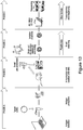
- the method further comprises: providing a second plurality of entities in a second fluid; preparing a second droplet from the second fluid; and fusing the first droplet prepared from the first fluid and the second droplet prepared from the second fluid to obtain a fused droplet; wherein said extracting comprises extracting the fused droplet by transferring the fused droplet from the first fluidic flow path into the second fluidic flow path. This may allow for obtaining a fused droplet which contains first and second cells, a cell and a reagent, and other combinations.
- Fusing the droplets may be performed using electrocoalescence, by electrically charging one or both of the first and second droplets, by passive or mechanical fusion, for example by providing flow channels with a shaped formation or other configuration to force droplets together, by employing chemically facilitated fusion, and/or using other techniques.
- Fusing first and second droplets may therefore allow to, for example, investigate how a single cell (or a number of cells) reacts to a reagent. Furthermore, stability tests may be performed on a single cell (or a number of cells) being exposed to a reagent, or interactions between a single cell-pair (or combination of cells) may be analysed.
- the determination and/or sorting are performed prior to the fusion of the droplets.
- the method further comprises: determining whether the second droplet contains one or more entities of the second plurality of entities, or whether the second droplet does not contain a said entity of the second plurality of entities; and sorting the second droplet dependent on an outcome of the determination.
- determining whether the second droplet contains one or more entities of the second plurality of entities, or whether the second droplet does not contain a said entity of the second plurality of entities and sorting the second droplet dependent on an outcome of the determination.
- the fusing is performed only for a said first droplet and a said second droplet which have been determined to contain one or more target entities of the first and second pluralities of entities, respectively.
- Implementations of the method therefore allow, for example, for analysing a single pair of cells, or a single pair of a cell and a reagent, such as a biomolecule, or a single target combination of one or more cells with one or more reagents, which are contained in a single droplet.
- a reagent such as a biomolecule
- the fused droplet contains a single pair of two cells, or a single pair of a cell and a reagent, or a single combination of one or more cells, or a single combination of one or more cells with one or more reagents, in particular wherein the reagent is a biomolecule. It will be appreciated that other combinations of a single pair of two entities contained in a single droplet may be analysed and/or further processed using implementations of the method described herein.
- the sorting comprises detecting a said droplet at a plurality of locations of said fluid flow path at different points in time to determine a velocity of a said droplet in said fluid flow path for timing said sorting.
- Implementations of the method allow for improved control of sorting the droplet(s) as a certain location of the droplet(s) in the fluidic flow path can be determined and/or predicted.
- a pair of sensors such as light gate sensors, may be used to estimate the speed of travel of a droplet.
- the position of the droplet at a future time may then be predicted. This may be used, for example, to check that a droplet is present in or has been directed/sorted into a correct channel, by checking that a droplet is present at the expected time and place.
- a method of preparing a droplet containing a single pair of two biological entities comprising: providing a first plurality of biological entities in a first fluid and providing a second plurality of biological entities in a second fluid; preparing a first droplet from the first fluid and preparing a second droplet from the second fluid; determining whether the first droplet contains a single entity of the first plurality of biological entities and whether the second droplet contains a single entity of the second plurality of biological entities; and fusing the first droplet and the second droplet which have been determined to contain a said single entity, respectively.
- the probability for obtaining a single pair of two entities in a single droplet may therefore be increased, as the determination step, in this example, for both of first and second droplets, respectively, is performed prior to fusing the droplets.
- the fused droplet may then be extracted from a first fluidic flow path of the fluid by transferring the sorted droplet from the first fluidic flow path into a second fluidic flow path.
- the first and second droplets may each go through all the steps of the above-described first aspect, and preferred implementations thereof. The probability for obtaining a fused droplet which contains a single pair of entities from the first plurality of biological entities and the second plurality of biological entities, respectively, may thereby be significantly increased.
- Fusing the droplets may be performed by electrocoalescence, by electrically charging one or both of the first and second droplets for fusing the droplets by electrostatic attraction, by passive or mechanical fusion, by chemically facilitated fusion, or by other techniques.
- a method of metabolising and/or analysing a biological entity contained in a droplet wherein the biological entity comprises a single cell, or a single pair of two cells, or a single pair of a cell and a reagent, the method comprising providing the biological entity contained in the droplet using the method of any one of the aspects and implementations described above.
- the metabolising (growing) may comprise increasing an entity in number, for example in the case of bacteria, or may comprise allowing an entity such as a mammalian cell to metabolise, for example to produce a product.
- implementations of the method described herein result in a very high monoclonality assurance, they are particularly suitable for growing, for example, a single cell (or biomolecule, or another entity) contained in a single droplet, because cells in a cell population grown from a single cell have a very high probability of all being substantially identical to each other.
- analysing a single cell in a single droplet allows for ensuring that any measurements are performed on the cell of interest. This may not be guaranteed for a large number of cells contained in a single droplet since, for example, mutations may result in a statistical distribution of cells (or other entities) which may not all be substantially identical.
- a microfluidic system for providing a droplet containing one or more entities, the system comprising: a droplet formation device for preparing a droplet from a fluid which contains a plurality of entities; an analyser for determining whether a said droplet contains one or more entities of the plurality of entities; a droplet sorting device for sorting a said droplet dependent on an outcome of the determination; and a decoupler for decoupling a said sorted droplet from a fluidic flow path of the fluid in the microfluidic system.
- the microfluidic system further comprises a further analyser configured to identify a said decoupled droplet (or a said sorted droplet which has been transferred from a first fluidic flow path into a second fluidic flow path via, for example, the decoupler), and a droplet dispensing unit which is configured to eject the identified droplet into, for example, a reservoir (e.g. a microtitre plate).
- a further analyser configured to identify a said decoupled droplet (or a said sorted droplet which has been transferred from a first fluidic flow path into a second fluidic flow path via, for example, the decoupler)
- a droplet dispensing unit which is configured to eject the identified droplet into, for example, a reservoir (e.g. a microtitre plate).
- the analyser(s) is (are) configured to determine whether a droplet contains a single target entity of a plurality of entities and/or whether the droplet contains a single target combination of entities of a plurality of entities.
- Implementations of the microfluidic system therefore allow for obtaining a single entity, for example a single cell or a single pair of biological entities, in a single droplet, or a single target combination of entities.
- Each of the droplet formation device, the analyser and droplet sorting device, and the decoupler allow for obtaining one or more target entities in a single droplet with a certain probability.
- the combined probability for obtaining a single entity or a single combination of entities in a single droplet using implementations of the microfluidic system may be higher than 99.9%, in particular higher than 99.99%.
- the decoupler may thereby comprise an analyser for a further determination as to whether a single droplet contains a single entity.
- the decoupler comprises an isolation unit for isolating a said sorted droplet from the fluidic flow path and a guide for guiding a said isolated droplet into a second fluidic flow path of the microfluidic system. This may be particularly preferable since a single entity (or a single combination of entities) contained in a single droplet may then be isolated and dispensed and/or analysed separately from other droplets or fluid.
- the guide comprises a rotating unit, wherein the rotating unit comprises a droplet storage unit for storing a said isolated droplet, and wherein the rotating unit is configured to be rotated to transport a said isolated droplet stored in the droplet storage unit into the second fluidic flow path.
- the droplet may be placed in the droplet storage unit, and the rotating unit may be rotated to then provide the droplet to the second fluidic flow path.
- the rotating unit completes the first and second fluidic flow paths.
- a branched flow channel may be used for a similar purpose, more particularly for selecting/dispensing droplet.
- the droplet storage unit may be a channel which completes the first and second fluidic flow paths, respectively.
- the guide comprises a translational unit, wherein the translational unit comprises a droplet storage unit for storing a said isolated droplet, and wherein the translational unit is configured to be moved in a translational direction to transport a said isolated droplet stored in the droplet storage unit into the second fluidic flow path.
- the droplet may be placed in the droplet storage unit of the translational unit, and the translational unit may be moved to then provide the droplet to the second fluidic flow path.
- the translational unit completes the first and second fluidic flow paths.
- the droplet storage unit may be a channel which completes the first and second fluidic flow paths, respectively.
- the guide may be configured such that it combines an input channel with two or more output channels.
- a channel of the guide may thereby be moved in a swinging-like motion, allowing connecting of an input fluidic flow path with a plurality of output fluidic flow paths.
- the microfluidic system further comprises an incubator for incubating the droplet for growing and/or maintaining the one or more entities.
- an incubator for incubating the droplet for growing and/or maintaining the one or more entities.
- the incubator may be placed in front of the analyser in a fluidic flow path direction, and/or it may be placed behind the analyser and droplet sorting device in a fluidic flow path direction. Additionally or alternatively, the incubator may be placed behind the decoupler in a fluidic flow path direction in the microfluidic system.
- the incubator comprises a stability test unit for performing a stability test on the one or more entities during the incubation.
- Performing a stability test on one or more entities for example a cell (or cells)
- Performing a stability test on one or more entities allows for sorting viable entities which have not degraded, changed production of a key analyte or biomolecule or died during the stability test. This allows for obtaining an even higher monoclonality assurance of viable entities, such as, but not limited to viable cells, biomolecules and other entities and/or cells that produce high levels of the key analyte or the like.
- the microfluidic system further comprises a dispensing unit for dispensing the decoupled droplet.
- the decoupled droplet may thereby be dispensed into, for example, individual wells of a microtitre plate where the one or more entities contained in the single droplet (or multiple droplets) may be stored and afterwards retrieved for further processing or analysis, or for subsequent use, for example in fermenting or the like.
- the dispensing unit comprises a reservoir for storing a growth media fluid, and wherein the dispensing unit is configured to dispense a said decoupled droplet in the growth media fluid.
- the dispensing step and the step of placing the single droplet containing the one or more entities in a growth media fluid may be combined in a single step.
- a droplet may be prepared from the growth media fluid which contains the entity or entities-containing droplet, which may then be dispensed into, for example individual wells of a microtitre plate.
- the dispensing unit comprises an increased (or decreased) pressure unit for dispensing the droplet via pressurised fluid ejection.
- the change in pressure may be produced by many techniques including, but not limited to: piezoelectric, thermal, and pressurised gas methods. Ejecting a droplet via pressurised fluid ejection may be particularly preferable, since the time to dispense a droplet from the microfluidic system may be significantly shortened, and/or the ejection via different outputs may be controlled, as will be further described below.
- the droplet formation device comprises a plurality of droplet formation devices
- the microfluidic system further comprises a droplet fusion device for fusing a plurality of droplets prepared using the plurality of droplet formation devices. Implementations of the microfluidic system therefore allow for preparing assays of, for example, a single pair of cells, or a single pair of a cell and a reagent, or a single combination of specific entities contained in a single, fused droplet.
- the droplet fusion device may be placed in front of the analyser and droplet sorting device in a fluidic flow path direction in the microfluidic system.
- the droplet fusion device may be placed behind the analyser and droplet sorting device in a fluidic flow path direction, as this allows for fusing only droplets which have been determined to contain one or more target entities of a first and second plurality of entities, respectively.
- the droplet fusion device may alternatively be placed behind the decoupler.
- An advantage of doing so is that the probability of two droplets each containing one or more entities of interest may be comparatively high prior to fusing those droplets.
- the droplet fusing device may comprise an electric field generator for generating an electric field for fusing the droplets by electro-coalescence.
- the droplet fusion device may comprise one or more charging devices for electrically charging droplets. Fusion of droplets is thereby promoted via electrostatic attraction of droplets.
- Droplet fusion may alternatively or additionally be achieved by providing a droplet fusion device which comprises channel geometries which allow for passive droplet fusion, for example via channel constructions at which a droplet may impact onto another droplet to thereby fuse with the other droplet.
- the analyser comprises one or more of a fluorescence detector, a scattered light detector, an acoustic wave generating and detecting unit, and a magnetic-activated cell sorting device.
- the content of a droplet may be determined via one or more of these devices, and the droplet may be sorted in the droplet sorting device according to the determination. It will be understood that one or more particular methods or devices for analysing the content of a droplet may be preferred over other methods or devices depending on the target content which is to be detected in a droplet.
- the analyser and/or droplet sorting device comprises a plurality of sensors for detecting a said droplet at different locations of said microfluidic system (at different points in time) to determine a velocity of said droplet in said microfluidic system, and wherein said droplet sorting device is configured to sort said droplet dependent on an outcome of said velocity determination.
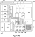
- a droplet sorting or dispensing device comprising a substrate bearing: a set of one or more microfluidic input channels; a set of microfluidic output channels; a moveable sorting element between the input channels and the output channels, wherein the sorting element comprises a set of microfluidic channels to connect the input channels to the output channels, and wherein the sorting element is moveable between a first position in which at least a first said input channel is connected to allow fluid flow from the first input channel to a first said output channel and a second position in which a length of fluid in a said channel and bearing one or more droplets is moved such that the length of fluid flows into a second said output channel.
- Implementations of the droplet sorting/dispensing device therefore allow for extracting a droplet from a first fluidic flow path by transferring the droplet from the first fluidic flow path into a second fluidic flow path.
- the droplet sorting device may be used to connect and/or complete microfluidic channels of a microfluidic device. As outlined above, this may be particularly preferable as a droplet may be decoupled from the first fluidic flow path of the microfluidic system, and dispensed from the system by, for example, pressurised fluid ejection from the second fluidic flow path.
- the sorting element is rotatable between first and second positions to swop lengths of fluid from first and second input channels so that they flow either to respective first and second output channels or are swopped to flow to respective second and first output channels.
- a prior determination as to the constituents of a droplet may therefore allow for sorting droplets by extracting a droplet of interest (or alternatively a droplet which is not of interest) from a first fluidic flow path and provide it to a second fluidic flow path based on the determination.
- Implementations of the droplet sorting/dispensing device therefore allow for extraction of a droplet from a fluidic flow path without disrupting the fluidic flow path within a microfluidic system.
- a method of sorting or dispensing droplets comprising: providing first and second microfluidic flows, at least one of said flows containing droplets; and rotating a turntable comprising portions of said flows to selectively direct droplets to one of first and second output microfluidic flows. Implementations of the method therefore allow for sorting droplets, for example based on a prior determination as to the properties of the droplets and/or their contents.
- a device for sorting or dispensing droplets in microfluidic flows comprising: first and second input microfluidic flows, at least one of the flows containing droplets; first and second output microfluidic flows; and a rotating turntable comprising portions of flows between the input and the output flows; and a controller to control rotation of the turntable to selectively direct the droplets to the first and second output microfluidic flows.
- the turntable may be turned such that the droplet may exit at the second output microfluidic flow. If, based on a previous analysis of a droplet and/or its content(s), it is desired to maintain the droplet in a channel, the turntable is not turned so that the droplet flows, for example, from the first input microfluidic flow via a portion of flow of the rotating turntable to the first output microfluidic flow.
- a cell, biomolecule and entity sorting or dispensing device for transferring a picodroplet from a first fluidic flow path to a second fluidic flow path
- the sorting device comprising: a decoupler for decoupling a said picodroplet from a said first fluidic flow path; and a guide for guiding a said decoupled picodroplet to a said second fluidic flow path, wherein the guide comprises: a rotating unit configured to be rotated for transporting a said decoupled picodroplet to a said second fluidic flow path; and/or a translational unit configured to be moved in a translational direction for transporting a said decoupled picodroplet to a said second fluidic flow path.
- a droplet is to be decoupled and guided from the first fluidic flow path to the second fluidic flow path may have been determined prior to the droplet entering the sorting device. Alternatively or additionally, this determination may be made when a droplet is inside the sorting device.
- the cell, biomolecule and entity sorting device further comprises an x-y moving platform comprising one or more microtitre plates, and/or one or more glass slides, and/or one or more arrays or other formats onto which one or more of the picodroplets are dispensable at one or more addressable locations.
- the droplets may therefore be dispensed into the one or more individual wells of microtitre plates, and/or one or more glass slides, and/or one or more arrays or other formats according to a pre-defined pattern, and the droplets and its contents may then be analysed and/or processed further, for example to grow populations.
- Implementations of the droplet sorting/dispensing device, and/or Implementations of the cell, biomolecule and entity sorting/dispensing device described herein may be incorporated into a droplet dispenser, in particular a picodroplet dispenser.
- a droplet dispenser is configured to selectively dispense a selected (sorted) droplet from a microfluidic channel into a reservoir.
- implementations of the droplet sorting/dispensing device, and/or implementations of the cell, biomolecule and entity sorting/dispensing device, and/or implementations of the picodroplet dispenser described herein may be included in a microfluidic device.
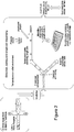
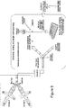
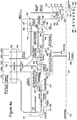
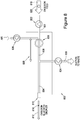
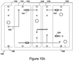
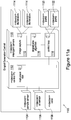
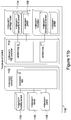
- a microfluidic cartridge for automated sorting and dispensing of sorted microfluidic droplets, the cartridge comprising: a sorting input channel coupled to a sorting region, said sorting region comprising two or more sorting output channels coupled to said input channel and a droplet director to selectively direct a droplet from said sorting input channel to a selected one of said sorting output channels; and a droplet dispenser coupled to one of said sorting output channels to dispense selected said droplets from said cartridge for collection in a reservoir, wherein said droplet dispenser comprises a droplet ejection mechanism to eject droplets from an emulsion flow into a dispenser output channel for collection in said reservoir.
- Implementations of such a cartridge provide a disposable/consumable device which can be used to address a number of important problems, such as identifying and collecting a target which may only be present in one in 10 6 or 10 9 droplets, for example a drug-resistant bacterium. In broad terms this may be done by identifying a signal from the droplets of interest and then collecting these droplets for further analysis, in principle in a common reservoir but in some preferred implementations in separate, identifiable reservoirs. This latter approach allows cells or other entities with individually identified properties to be retrieved from, say, a multi-well plate for subsequent analysis or use - effectively individual wells of such a multi-well reservoir may be used to collect individual entities with selected properties.
- the cartridge may be used in a 'stability test mode' to identify changed (for example, negative) responses in a population of droplets (for example cells) which are notionally all identical.
- the cartridge in this mode of operation can be used, for example, to identify individual instances where production of a substance by a cell has been switched off, say to troubleshoot falling yields in a fermentation batch.
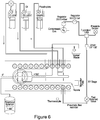
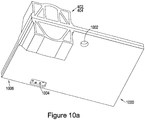
- the cartridge includes an incubation region or chamber where droplets can be held, preferably at a controlled temperature to allow incubation of the contents of the droplet prior to controlled release.
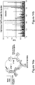
- this region is configured to hold the droplets at a greater density than when dispersed within the emulsion; this may be achieved by holding the droplets (which typically 'float') in an upper portion of the chamber and providing a valve or similar at the top of the chamber for controlled release of the droplets - in use the cartridge is orientated with the top of the incubation chamber upwards. Excess carrier fluid (oil) may be released to waste.
- the incubation region is upstream of the sorting region.
- the emulsion (which may be a double emulsion) is generally a water-in-oil emulsion.
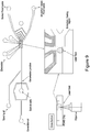
- the cartridge is preferably configured to interface with a microdroplet processing system - that is in implementations the cartridge can be attached into and released from the microdroplet processing system, which provides sensing and control functions.
- the microdroplet processing system provides temperature control for the incubation chamber and droplet property sensing for droplet sorting, and may also provide relative motion between the dispenser output channel and reservoir wells to collect the droplets.
- the cartridge generally has the form of a flat plate bearing microfluidic channels, one or more holding regions, valves and the like. It is preferably substantially optically transparent, and may be fabricated from a range of plastic materials, for example polydimethylsiloxane (PDMS) or cyclic olefin polymer or copolymer (COP or COC).
- PDMS polydimethylsiloxane
- COC cyclic olefin polymer or copolymer
- the cartridge may then be mounted vertically or at a suitable angle in the system/instrument with the dispenser output channel directed downwards towards a multi-well or microtitre plate. The instrument may then move the cartridge and/or plate to direct the output channel into a selected well.
- the cartridge is provided with a plurality of fluidic connections, which may be made automatically when the cartridge is inserted into the instrument. Generation of the emulsion may be performed on-cartridge or off-cartridge.
- the cartridge may be provided with reservoirs along one edge (so that these are in the correct orientation when the cartridge is vertical), to hold oil and aqueous medium (such as water and growth medium) for droplet-on-chip droplet generation.
- Implementations of the microfluidic cartridge are, are previously described, directed towards identifying a very few, extremely rare droplets containing a biological entity of interest from a very large population.
- the droplet sorter may operate one or two orders of magnitude faster than the droplet dispenser - for example the dispenser may operate at 1-10Hz whereas the sorter may operate at 100-1,000Hz. Nonetheless, because of the statistics of the target entities, the dispenser may not operate continuously.
- one or more emulsion flow buffer regions are provided between the sorting region and the dispensing region of the cartridge, to control an emulsion flow rate to the droplet dispenser.
- such a buffer region may comprise a chamber, somewhat akin to the incubation region previously described, where droplets can accumulate whilst excess oil is siphoned off or released to waste.
- droplets may be allowed to float to the top of the chamber from where they can be released in a controlled manner by a valve or the like.
- a buffer region in implementations this may comprise a length of microfluidic channel, for example in a serpentine configuration, arranged so that an order of the droplets is maintained. In this way the identity of a droplet having a droplet characteristic measured upstream of the buffer may be maintained since the order or sequence of droplets is maintained.
- a widened channel or chamber may be employed, which has the advantage of facilitating the provision of a larger capacity. In this case the characteristics of droplets may be measured after their exit (in sequence) from the buffer region.
- preferred implementations link one or more characteristics of a droplet to an identifiable property of a droplet, typically its position, so that when the droplets are dispensed into wells/reservoirs the properties of the droplet(s) within a well/reservoir are known.
- the contents of a dispensed droplet in an identified well/reservoir are known and stored for later use.
- droplet contents for example a cell, protein, antibody, reagent or analyte
- a desired/target property can be retrieved after droplet dispensing by retrieving the contents of a well/reservoir known (recorded) to have contents with the desired/target properties.
- the output channel of the dispenser includes a mechanism to promote liberation of a droplet, or the contents of a droplet, from the emulsion.
- the contents of a droplet typically comprise water and a biological entity, such as a cell, often in a growth medium.
- the purpose of the cartridge is to extract those (rare) biological entities which have a particular property or characteristic, and this is done by collecting target droplets in one or more reservoirs, which may already contain, say, 20-50 ⁇ l of water/growth medium in the well of a microtitre plate.
- an ejected slug of emulsion may have a volume of 50-300nl (depending in part upon the channel width) whilst a droplet may have a volume of order 50pl or larger.
- Implementations of the droplet ejection mechanism therefore preferably comprise a system to extract the droplet from the emulsion and/or to break up a droplet.
- This may be achieved mechanically by shaping, for example narrowing, a nozzle of the dispenser output channel and/or by providing a mesh across the output channel; and/or this may be achieved electrically, for example by providing a pair of electrodes adjacent the exit of the dispenser output channel across which a voltage can be applied to generate an electric field to disrupt the emulsion/droplet; and/or a chemical mechanism may be employed, for example by adding a stream of de-emulsification agent such as perfluorooctanol into the dispenser output channel.
- the microfluidic cartridge further comprises a plurality of sensors for detecting a said droplet at different locations of said microfluidic cartridge (at different points in time) to determine a velocity of said droplet in said microfluidic cartridge, and wherein said droplet director is configured to direct a said droplet dependent on an outcome of said velocity determination.
- a plurality of sensors for detecting a said droplet at different locations of said microfluidic cartridge (at different points in time) to determine a velocity of said droplet in said microfluidic cartridge, and wherein said droplet director is configured to direct a said droplet dependent on an outcome of said velocity determination.
- the droplet ejection mechanism comprises a mechanism to increase a pressure in the emulsion flow to direct droplets into the dispenser output channel.
- this may be achieved by arranging the dispenser output so that it has a main channel and a side channel (in a form of T-junction, as described later) and then applying a pressure pulse to drive a droplet into the side channel (dispenser output channel) for output.
- such an arrangement may comprise a pair of valves, such as pinch valves, along the length of an emulsion flow with the side channel (dispenser output channel).
- valves can be closed to isolate the flow and then pressure applied to the isolated slug of emulsion, to drive the emulsion containing the droplet into the dispenser output channel.
- a slug of emulsion may be transferred from a first channel/flow to a second, where a pressure pulse may be applied to eject the slug and its associated droplet.
- a suitable pressure pulse may be provided mechanically, for example using a piezoelectric transducer.
- a pressure pulse may be generated electrically, for example by means of an electrical heating element and bubble expansion (in a similar manner to an ink-jet printer).
- an increased pressure pulse is applied to eject a slug of emulsion with its droplet, but the skilled person will appreciate that in principle the arrangements we describe later may be adapted so that instead a pulse of reduced pressure is used to eject droplets from an emulsion flow into the dispenser output channel.
- this is achieved by using the instrument housing the cartridge (microdroplet processing system) to sense one or both of the position and the speed of a droplet selected by the sorting system for ejection.
- the sensing may be performed upstream of the droplet ejection mechanism so that the position of the droplet can be predicted when the droplet reaches the ejection mechanism.
- droplet speed need not be measured if the rate of flow of emulsion can be controlled sufficiently accurately, but in practice measuring the speed is advantageous. It is further advantageous to control the channel size tolerance, to reduce variations in channel size and hence droplet speed variations. Imaging the droplets in a separate location to the droplet ejection mechanism in this manner makes the cartridge/instrument simpler and more effective.
- droplets are dispensed into individual wells of a microtitre plate or the like, comprising a plurality of separate wells.
- the instrument may then comprise a control system to selectively direct a dispensed droplet to a reservoir.
- the cartridge or the multi-well plate is mounted on an X-Y moveable stage so that the cartridge and plate may be moved relative to one another to direct the dispenser output channel to a selected reservoir.
- a well may hold one or more droplets, depending upon the application/assay/mode of operation of the instrument.
- corresponding data is stored for a selected, target droplet with desired properties.
- This data is then associated with information identifying a particular well or reservoir into which the droplet is dispensed.
- a droplet with particular properties can afterwards be retrieved from its reservoir for later analysis and/or a multi-well reservoir can be used to extract a set of droplets with a particular property or range of properties.
- the sorting may be based on, say, comparison of a measured value with a threshold value it is possible for the selected droplets to have a range of values of a parameter, which may in turn correlate with some other property measuring activity of the biological entity within the droplet.
- an optical property such as one or more of a degree of fluorescence, a degree of scatter, a degree of luminescence, a degree of absorbance
- electrical or magnetic properties such as an electrical conductance
- one more derived or inferred properties such as whether a cell is living or dead (which may be inferred from an optical measurement).
- the sensed data stored in association with reservoir identification data may additionally or alternatively be sensed after sorting, by a separate arraignment of sensors.
- implementations of the combined cartridge and instrument facilitate tracking of individual dispensed droplets for later analysis or use.
- a direct droplet assay and a biological entity stability/viability assay.
- an assurance of monoclonality is important - that is, it can be desirable for individual reservoirs/wells which contain a biological entity such as a cell to contain just a single such entity. This is important, for example, where an antibody is being generated from a cell line - it can be important for regulatory purposes to be able to substantially guarantee that an antibody has been derived from a single clone of cells if, say, the antibody is being used to create a drug.
- the incubation chamber is generally not needed, and thus a cartridge version without such a chamber may be employed.
- a more generic cartridge may be provided in which the incubation chamber may be bypassed or, in another version, droplets may be passed through the incubation chamber as previously described but without incubation.
- One way in which implementations of the microfluidic cartridge may be used for monoclonality assurance is to use the droplet sorter to select droplets containing just a single cell, sending empty droplets and droplets with two or more cells to waste.
- the number of cells in a droplet may be determined optically, for example by detecting optical absorbance, scattered light, fluorescent light, or (in some preferred implementations) by visualising and counting individual cells within a droplet.
- Such an approach is facilitated by generating droplets with a strong statistical bias towards creating empty droplets.
- a droplet generation system employs flow focusing and generates droplets containing a number of biological entities which obeys Poisson statistics.
- Monoclonality assurance is facilitated by operating such a system so that less than half the droplets contain a biological entity, preferably less than 30%, 20% or 10% - for example the system may be operated so that only around 5% of the droplets contain a single entity/cell.
- this second sorting stage may effectively be combined with the droplet dispenser - that is the dispenser may, in implementations, be configured to itself select droplets with a defined number (or numeric range) of biological entities per droplet.
- the droplet ejection mechanism may be selective, dependent upon confirmation that that a droplet contains only a single biological entity or, more generally, a defined number or numeric range of biological entities.
- detection of the number/number range of entities per droplet may be made by the sensor(s) employed to sense the speed/position of a selected droplet, as previously described. In this way an extremely high degree of monoclonality assurance can be provided.
- the above described techniques may be adapted to target a defined number of biological entities per droplet rather than particularly a single entity per droplet.
- a numeric range is more appropriate; this may define a few tens of organisms per droplet, for example 25-35 entities per droplet.
- a microfluidic cartridge of the general type described above may provide a fusion assay' or functional assay mode of operation.
- the microfluidic cartridge is provided with a droplet fusion region having at least two input channels and at least one output channel to provide an input to the sorting region (the incubation region, where present, may be either before or after the sorting region).
- the incubation region where present, may be either before or after the sorting region.
- the droplet fusion region is used to combine biological entities upstream of the sorting region so that a fused droplet may be selected based on a potentially rare interaction between the combined entities.
- the two (or more) emulsions comprising the droplets to be fused may be generated on or off the cartridge.
- a system can be used to identify very rare cases when one biological entity is resistant to another, potentially down to a probability of one in one million or one in one billion.
- examples may comprise a T-cell resistant to infection by HIV or a bacterium resistant to a phagocyte; the skilled person will readily be able to appreciate that implementations of the system may be used to identify other similar situations.
- cell sorting may be based upon any of a variety of physical properties, typically optical properties; in one approach a determination is made of whether an entity within a droplet is alive or dead.
- three or more output channels may be provided, for example to sort a mixed population of entities into groups or categories (sorting into multiple channels may be achieved, for example, by selectively directing droplets using pairs of electrodes to apply an electric field).
- the population may be sorted into groups of high, medium and low productivity and it may be, for example, that the cells with medium productivity are more desirable than those with high productivity because they are subsequently more robust in a large scale fermentation system.
- any one or more of the output channels may be employed for collecting the contents of selected droplets for further processing/analysis.
- the cartridge in use broadly speaking a sample, and oil are loaded into separate sterile reservoirs on one edge of the cartridge (the cartridge is mounted vertically or at a suitable angle) and an emulsion is generated.
- the emulsion is pumped to the incubation chamber where the droplets float upwards and the excess oil runs to waste.
- the incubation chamber is then heated, for example to 37°C for some period of minutes to hours, and then cooled, for example to around 8°C, to limit metabolism.
- the droplet population is then moved (pumped) to the sorting region where target droplets are selected and moved from there to a holding region, again removing excess oil (syphoning off or allowing the excess to run to waste) droplets are then released one by one from the holding region (additional oil is added to facilitate this process) and moved to the dispensing region where the droplet ejection mechanism ejects selected droplets into a common or individual reservoirs for the droplets.
- cartridges which may have a number of droplet processing regions, in particular for droplet generation, droplet incubation, droplet sorting, droplet holding ("buffering"), and droplet dispensing.
- the cartridge is provided in a modular form, having a base or substrate to which separate modules to perform some or all of these functions may be attached as desired. This may be facilitated by having a standard interface or set of interfaces between modules of such an arrangement.
- a microfluidic system for providing one or more target entities in a droplet, the microfluidic system comprising: a first detector for detecting one or both of: whether a said droplet contains a said target entity or target entities; and a property of a said target entity or target entities; the microfluidic system further comprising: a sorting device for sorting a said droplet dependent on an outcome of said detection; and a droplet dispensing unit for dispensing a said sorted droplet at one or more target locations, wherein said microfluidic system is configured to correlate a said target location with a said property of a said target entity or target entities detected in said first detector.
- the droplets may thereby be dispensed into individual wells of a microtitre plate, or onto another medium. Since a droplet may be dispensed based on the detection in the first detector, a droplet at a specific target location (which may, for example, be a well of a microtitre plate) may be correlated to the properties of a droplet as a whole and/or its constituents (if any). These properties may be, but are not limited to one or more of a level of fluorescence, a level of scatter luminescence, an absorbance level, a conductivity level, and other chemical and/or physical properties.
- implementations of the methods/systems we describe, according to both this and other aspects, can be used to determine which droplet/reservoir (for example which well of a multi-well plate) has which properties. This may be used later to identify, and more particularly be able to provide a sample, of a cell or biological entity responding in a particular way to whatever assay or test is being performed by the microfluidic system (because a target entity/droplet with identified properties is held within an identified well, and because, in implementations, a record of log is kept of which droplet/cell/entity is dispensed into which reservoir/well).
- the sorted and analysed droplets may be dispensed into a single reservoir.
- the microfluidic system further comprises a second detector for detecting a said property of a said target entity or target entities, wherein said droplet dispensing unit is further configured to correlate a said target location with a said property of a said target entity or target entities detected in said second detector.
- These one or more further analysis may thereby increase, for example, a probability of identifying one or more target entities, in particular a specific numerical number of target entities, in a droplet, and/or a probability of identifying one or more target entities with a specific property (e.g. a specific fluorescence level, which may be within a specific range of fluorescence levels).
- a specific property e.g. a specific fluorescence level, which may be within a specific range of fluorescence levels.
- the droplet dispensing unit comprises a second sorting device for transferring a said droplet from a first fluidic flow path to a second fluidic flow path, said second sorting device comprising: a decoupler for decoupling a said droplet from a said first fluidic flow path; and a guide for guiding a said decoupled droplet to a said second fluidic flow path, wherein said guide comprises: a rotating unit configured to be rotated for transporting a said decoupled droplet to a said second fluidic flow path; and/or a translational unit configured to be moved in a translational direction for transporting a said decoupled droplet to a said second fluidic flow path.
- the second sorting device may be used to isolate a droplet of interest based on a prior analysis. Therefore, a probability of a dispensed droplet having one or more target entities, in particular a specific numerical number of target entities, in a droplet, and/or one or more target entities with a specific property, may be increased by isolating the droplet from the first fluidic flow path.
- the droplet dispensing unit comprises a microfluidic channel junction comprising an input channel and a plurality of output channels, wherein said droplet dispensing unit is configured to control into which one of said plurality of output channels a said droplet is guided based on said detection via said first and/or second detectors.
- droplets which are not of interest may be put to waste.
- Other droplets may be sorted according to the properties of their constituents (if any) while the droplets are dispensed from the microfluidic system based on the previous analysis in the first and/or second detectors.
- microfluidic system further one or more detectors and/or analysers may be exploited in the microfluidic system, and the dispensing of a droplet off the microfluidic system may be correlated to one or more of these further analysis in the one or more detectors and/or analysers.
- the droplet dispensing unit comprises a pressure modulation unit for changing a pressure in a fluidic flow path of said droplet dispensing unit for controlling into which one of said plurality of output channels a said droplet is guided.
- a pressure modulation unit for changing a pressure in a fluidic flow path of said droplet dispensing unit for controlling into which one of said plurality of output channels a said droplet is guided.
- controlling the output channel from which a droplet is to be dispensed may be controlled by one or more of controlling a temperature of a droplet using a heater, using piezoelectric electrodes, using acoustic actuators, and exploiting other physical and/or mechanical properties of a droplet.
- a first said output channel is connected to said input channel generally in a fluidic flow path direction of said input channel, wherein a second said output channel branches off from said input channel, wherein said droplet dispensing unit further comprises a pump connected to said second output channel, wherein said pump is configured to suck off a said droplet from said input channel, and wherein said pressure modulation unit is configured to increase a pressure in said input channel in response to a said detection in said first and/or second detector to eject a said droplet via said first output channel.
- the pressure may be increased in the input channel, such that the droplet is provided to the first output channel, rather than being sucked off by the pump into the second output channel.
- the pressure in the input channel may generally be above a threshold such that a droplet is, without a pressure change in the input channel, provided to the first output channel.
- the pressure in the input channel may be decreased such that the target droplet is sucked into the second output channel by the pump.
- the microfluidic system further comprises one or more droplet holding regions, wherein a said holding region is arranged between said sorting device and said droplet dispensing unit, and wherein a said holding region is configured to control a flow of a said sorted droplet to said droplet dispensing unit.
- the microfluidic system further comprises a plurality of sensors for detecting a said droplet at different locations of said microfluidic system (at different points in time) to determine a velocity of said droplet in said microfluidic system, and wherein said sorting device is configured to sort said droplet dependent on an outcome of said velocity determination.
- a plurality of sensors for detecting a said droplet at different locations of said microfluidic system (at different points in time) to determine a velocity of said droplet in said microfluidic system
- said sorting device is configured to sort said droplet dependent on an outcome of said velocity determination. This may be particularly advantageous as the location of the droplet(s) in the microfluidic system may be determined and/or predicted, which allows for an improved control of sorting the droplet(s) in the sorting device.
- a microfluidic chip comprising: a droplet generation region for generating microdroplets which contain one or more biological entities; a droplet incubator and/or storage region for incubating and/or storing said biological entities; a droplet sorting region for sorting said microdroplets based on one or more properties of said biological entities; and a droplet dispensing region for dispensing said sorted microdroplets; and wherein said droplet generation region, said droplet incubator and/or storage region, said droplet sorting region and said droplet dispensing region are incorporated on a single chip design of said microfluidic chip.
- microfluidic chip ensures sterility, ease of use and allows for significant cost-savings as the generator, incubator, sorting chip and dispenser are incorporated into a single microfluidic chip.
- the microfluidic chip comprises a microfluidic flow path diversion unit for changing a microfluidic flow path of a said microdroplet between said regions; and a control unit comprising a first processor for controlling said microfluidic flow path diversion unit.
- a control unit comprising a first processor for controlling said microfluidic flow path diversion unit.
- valves may be provided on the microfluidic chip which allow for controlling the flow or rate of flow of microdroplets thought the different regions of the microfluidic chip.
- the microfluidic chip further comprises a heater for locally heating droplets at the droplet incubator and/or storage region (and/or at other specific regions), and further comprising a second processor for controlling said heater.
- the first and second processor may be a single processor. Implementations may therefore advantageously allow for heating droplets and their constituents only at certain locations or regions of the microfluidic chip, such that heating of droplets in other regions of the microfluidic chip may be avoided.
- the microfluidic chip further comprises a cooler for locally cooling droplets at the droplet incubator and/or storage region (and/or other specific regions), and further comprising a third processor for controlling said cooler.
- the first, second and/or third processors may be a single processor. Implementations may therefore advantageously allow for cooling droplets and their constituents only at certain locations or regions of the microfluidic chip, such that cooling of droplets in other regions of the microfluidic chip may be avoided. Implementations which may provide heating (and optionally cooling) may allow for example for polymerase chain reaction to be performed at one or more specific regions of the microfluidic chip.
- microfluidic system the droplet sorting or dispensing device, the droplet dispenser, the microfluidic device, the microfluidic cartridge, the microdroplet processing system and the instrument for microdroplet-based processing of biological entities may also be implemented as preferred implementations in the microfluidic chip.
- an instrument for microfluidic droplet-based processing of biological entities comprising: a droplet generation system to generate one or more water-in-oil emulsions of droplets comprising biological entities; a droplet processing system to process said droplets; and a droplet dispensing system to dispense processed said droplets into one or more reservoirs; wherein said droplet processing system is configurable for multiple different modes of operation including at least a monoclonality mode of operation and an assay mode of operation.
- the droplet processing system includes at least a droplet sort function/unit and the monoclonality mode of operation comprises sorting droplets based on occupancy of the droplet by the biological entities.
- the assay mode of operation includes incubating the droplets, preferably but not essentially in a droplet incubation unit, prior to sorting. The sorting may then be based on a product of the biological entities during the incubation.
- the droplet processing system may further comprise at least one droplet fusion unit and the modes of operation may then include a fusion assay mode, sorting based upon the result of a combination of biological entities in one set of droplets with material, for example other biological entities, in a second set of droplets.
- the droplet processing system is embodied in one or more interchangeable or modular cartridges - that is, for example, a different cartridge may be provided for each of the different modes of operation or, alternatively, a modular cartridge may be employed in which different droplet processing functions - such as a sort function, incubation function, dispensing function and the like - may selectively be assembled on a cartridge substrate.
- a monoclonality mode of operation may comprise encapsulating the biological entities, typically cells, within droplets, preferably in a manner which is biased towards a majority of empty droplets. Those droplets which are then identified in the sorting unit as being occupied by a single cell are selectively directed to the droplet dispensing unit, where they are processed and dispensed.
- a single droplet may be dispensed into an individual well or reservoir, but it can also be acceptable to dispense two or more droplets into a reservoir or well. For example if the entities or cells are going to be re-injected for further processing then a well/reservoir may hold a larger number of droplets.
- an assay mode it can be acceptable to encapsulate more than one entity/cell per droplet, for example two or three cells per droplet.
- these are then provided to an incubation chamber where they are warmed and metabolise to produce a product such as a protein or the like.
- the product interacts with one or more reagents within the droplet creating a measurable signal, for example a fluorescence signal, and this may then be used to sort the droplets, for example to collect and dispense the best producers.
- a sorting unit may be provided prior to the incubation region, in particular to remove empty droplets before incubation. This helps to reduce the volume of the incubation chamber and is particularly advantageous where the droplet generation/entity encapsulation results in a large percentage of empty droplets - depending upon the process used 90% or more of droplets may be empty.
- a stability assay mode In another assay mode, which may be termed a stability assay mode, a similar incubation, selection and dispensing process may be employed, but with the aim of identifying a subgroup of the initial population.
- a subgroup may be a subgroup which exhibits optimum production, typically of a protein, for example for drug fabrication.
- the optimum production need not necessarily be the maximum production but may be, for example, consistent production (production which is maintained over a period rather than decaying with time), or production which is maintained over a (wide) range of environmental conditions.
- implementations of such a stability assay may be employed to identify those entities which are stable producers, for example to select producers for a production process such as a fermentation process, or for quality control of a production process.
- an entity may be encapsulated with one or more reagents within a droplet and then incubated, afterwards looking for a measurable signal, such as a fluorescence signal, which may then be used to differentiate a target sub-population of the entities for dispensing and collection in one or more reservoirs.
- a measurable signal such as a fluorescence signal
- a typical procedure involves generating two sets of droplets, at least one encapsulating biological entities; these may be generated in advance and provided in respective reservoirs or may be generated, for example, on-cartridge.
- the fusion assay may then comprise droplet fusion, incubation, sorting, and dispensing.
- pre-sorting may be employed, prior to incubation as previously described and/or after droplet fusion.
- a fusion assay may be employed, for example, for a toxicological study, environmental study, metagenomic study, a study of drug uptake, or the like.
- a drug may be provided in one set of microdroplets at a known concentration and the concentration of the drug may then be measured after incubation (either remotely or by taking an aliquot), to determine a change in concentration of the drug from which drug uptake may be inferred.
- the dispensing unit may also provide an additional selection step - that is the droplet dispensing the system may comprise a combined droplet sorting and dispensing stage.
- Figure 1 shows a schematic illustration of a first example of droplet detection, sorting and dispensing according to example implementations described herein. This mode is termed, in this example, monoclonality assurance mode.
- multiple cells are provided in a fluid, in this example water, optionally including a growth medium.
- individual droplets are formed from the fluid. As outlined above, this may be achieved by using, for example, T-junctions, Y-junctions, flow focussing devices, or other devices.
- the droplets which have been generated are, in this example, transported in a fluid of oil.
- the individual droplets which may or may not contain one or more cells, are then guided through the microfluidic device in an oil emulsion.
- the picodroplet cell suspension i.e. the droplets in the oil emulsion
- a detection and sorting device Whether or not a single droplet contains one or more cells may be detected in the analyser, based on one or more of electrical, optical, thermal, acoustic, mechanical, temporal, spatial, and other physical characteristics of the droplets.
- the droplet may be sorted in the droplet sorting device.
- picodroplets which do not contain one or more cells are put to waste.
- droplets which contain, in this example, the single cell of interest are guided towards a decoupler of the microfluidic system.
- Droplets which contain one or more cells of interest are then extracted from the first fluidic flow path and transferred into a second fluidic flow path.
- the target droplets are extracted from the first fluidic flow path in a growth media fluid.
- a droplet which contains a target cell, whereby the droplet is incorporated in the growth media fluid is then dispensed into a microtitre plate via pressurised fluid ejection.
- a pressure source is, in this example, attached to the flow path at which the growth media fluid is injected.
- the picodroplets may thereby be diluted.
- a robotic xy translational stage is provided in this example in order to dispense droplets into different wells of the microtitre plate.
- the droplet detecting, sorting and cell dispensing are, in this example, performed in a temperature controlled environment.
- picodroplets which contain a single cell and which are not to be disposed into the microtitre plate, are guided in the first fluidic flow path to waste.
- the probability for finding a single cell in a single droplet which is disposed into the microtitre plate may be higher than 99.997%.
- an automated plate stacker interface may be provided, in order to stack various microtitre plates on top of each other.
- an imaging device such as a camera is provided at or close to the point at which the droplets are dispended (into the microtitre plate).
- the imaging device may be used to image a droplet to determine whether the droplet contains just a single cell (or other biological entity), or alternatively two or more cells, or no cells.
- optical detection of scatter from a droplet may be detected for this purpose.
- Such an optical system may then be used as a tool to monitor monoclonality, more particularly in conjunction with a control system to identify and log when a well does not contain just a single cell (or vice-versa), for example so that the system may then flag an error for the identified well.
- Figure 2 shows a schematic illustration of a further example of droplet detection, sorting and dispensing according to implementations described herein. Two different modes of operation, a direct assay mode, as well as a stability test mode are displayed.
- cells are provided in a fluid together with assay reagents. Individual droplets are then formed from the fluid as outlined in the example shown in Figure 1 .
- the incubator may be used to grow and/or maintain the cells in the droplets.
- the incubator may comprise a stability test unit which allows for performing stability tests on the cells during the incubation. Performing a stability test on a cell in a single droplet allows for sorting only viable cells during the detection and sorting steps in the analyser and droplet sorting device, which have not degraded or died during the stability test.
- FIG. 3 shows a schematic illustration of a further example of droplet detection, sorting and dispensing according to implementations described herein. This mode is termed, in this example, picodroplet fusion assay mode.
- a picodroplet fusion assay mode is illustrated.
- the first cell type A is provided in a first fluid. Individual droplets are then formed from this first fluid.
- a second cell type B is provided in a second fluid, from which individual droplets are formed. Droplets which have been prepared from the first fluid, as well as droplets which have been prepared from the second fluid, are guided towards a fusion device (electrodes in Figure 3 ). In this example, two droplets from the first and second fluids, respectively, are prepared by electro-coalescence. The fused droplets may then be processed further as shown in the schematic illustrations of Figure 1 and/or Figure 2 .
- the droplet fusion device may be placed, for example, behind the analyser and droplet sorting device in a fluid flow direction of the microfluidic system.
- Such a configuration may allow for fusing droplets in the droplet fusion device only for droplets which have been determined to contain, in this example, cells which are of interest for growth and/or further analysis and processing.
- FIG. 4a shows a block diagram of an implementation of a microdroplet processing system/instrument 400 incorporating a (disposable) microfluidic cartridge 410 according to an example implementation.
- the instrument 400 has a reservoir 402 holding an aqueous medium, generally including growth media, within which biological entities such as mammalian cells, bacteria or the like are held for processing.
- a set of reservoirs 404a-d hold oil for providing an emulsion at various stages of the system.
- reservoirs 402, 404 are shown as part of the instrument rather than part of the cartridge, in other implementations (as shown in Figure 10a later) they may be part of the cartridge; depending upon the cartridge function, for example whether it is to be used for a fusion or functional assay, there may be more than one aqueous reservoir 402.
- the fluids from reservoirs 402, 404 are pumped by respective pumps in Figure 4a illustrated by fluid drive module 406, which again may be integrated with the cartridge.
- a set of fluid flow lines 408 connect to respective ports on the cartridge when the cartridge is inserted into the instrument, as also illustrated later with reference to Figure 12 .
- the illustrated cartridge 410 comprises a droplet generation region 412, a droplet incubation/storage region 414, a droplet sorting region 416, a flow buffer region 418, and a droplet dispenser 420.
- each of these regions is modular and an emulsion flow processing configuration may be selected by selecting modules to attach to a cartridge base or holder so that the selected modules interface with one another to perform the desired function for a particular cartridge.
- the smaller circular regions represent inlet/outlet ports for the droplet processing regions which, depending upon the cartridge configuration may represent on-cartridge or off-cartridge connections; the larger circular regions represent optical droplet sensing regions, and the crossed circles represent valves.
- the droplet generation module or region 412 of the cartridge comprises an aqueous sample inlet 422 and an oil inlet 424 for generating the emulsion. Flows of these liquids are provided to a flow focus junction 426 where the emulsion is generated and provided to an output channel 428 of the region.
- the generation oil may have a flow rate of 1400 ⁇ l per hour
- the sample for example a cell suspension
- the water-in-oil emulsion in the output channel may have a flow rate of 2400 ⁇ l per hour comprising 700 picolitre droplets at 1000Hz.
- the emulsion (which may alternatively be created off-cartridge and added to a reservoir) is then in this example provided to the incubate/storage region 414.
- This comprises a storage chamber 430 within which the individual droplets 432 float upwards whilst excess oil flows to waste through channel 434 (via a valve) into reservoir 436 from which, potentially, the oil may be recycled.
- the oil comprises fluorous oil, which is particularly suitable for trapping oxygen which allows for example for enhanced growth of, e.g. biological entities, such as cells, in the droplets while being stored in the chamber 430.
- the chamber 430 may therefore be filled up with fluorous oil above a threshold (e.g.
- the instrument in which the cartridge is located includes a heating device such as a heater plate and/or a cooling device such as a Peltier effect device adjacent the incubation chamber 430, preferably together with a temperature sensor for temperature control. In this way the chamber may be heated for a controlled period to incubate the contents of the droplets and then cooled to substantially inhibit the incubation.
- the incubation chamber has an outlet channel 438 with an optional side channel 440 to receive spacing oil to space the droplets in the emulsion in the outlet as they are fed out from chamber 430.
- the output channel 438 from the incubation region may have a flow rate of around 350 ⁇ l per hour; spacing oil may be added at port 440 or in the subsequent sorting region (see later) at a rate of around 8,000-11, 000 ⁇ l per hour.
- Sorting region 416 as an input channel 442 in this implementation coupled to the output channel 438 of the incubation region, and a pair of output channels 444, 446, channel 444 containing the desired droplets with their load of selected, target analyte (entity or entities).
- Channel 446 runs to waste reservoir 436.
- an inlet 448 is provided for adding spacing oil to the flow into the sorting region.
- the sorting region includes a region 450 where the droplet contents are (optically) interrogated by the instrument holding the cartridge, which then drives electrodes 452 to selectively direct droplets into either channel 444 or channel 446 (connections to electrodes 452 are not shown in Figure 4a , for simplicity).
- the mark:space ratio of droplets in the input emulsion for the sorting region 416 may be of order 1:10 to 1:20 and the droplets may enter the sorting region at the rate of a few 100Hz.
- the flow rate in channel 444 may be of order 5,000 ⁇ l per hour, containing between 1,000 and 10,00 droplets; the flow rate of emulsion in channel 446 may be substantially the same but this emulsion may comprise of order 190,000-2,000,000 droplets (per hour).
- the 'target' output channel 444 of the sorting region is coupled to an input channel 454 of space/hold or 'flow buffer' region 418.
- This comprises a chamber 456, typically somewhat smaller than the incubation chamber 430, within which droplets are temporarily held (for example floating at the top of the chamber) prior to release into output channel 458.
- the oil comprises fluorous oil, which is particularly suitable for trapping oxygen which allows for example for enhanced growth of, e.g. biological entities, such as cells, in the droplets while being stored in the chamber 456.
- the chamber 456 may therefore be filled up with fluorous oil above a threshold (e.g.
- the flow buffer region also includes an output channel 462 to waste reservoir 436.
- a 10ml volume of chamber 456 may hold 10,000 droplets.
- the output flow rate in channel 458 may be of order 4 ⁇ l per hour; the spacing oil in channel 460 may flow at around 5,000 ⁇ l per hour; the waste in channel 462 may flow at a variable rate of, for example, 10-5,000 ⁇ l per hour.
- the flow buffer region 418 output channel 458 provides an input via channel 464 to droplet dispenser region 420.
- the dispenser channel 466 provides a second input to the dispenser carrying eluent, that is oil used to/for extraction and ejection of target droplets.
- the dispenser has a first output channel 468 which again flows to waste, and a second output channel 470 which provides an outlet 472 for the dispenser for ejecting selected droplets for collection in a reservoir.
- a further channel 476 is coupled to an inlet 478, in this example to receive compressed air at pressure in the range of, for example, 0-2.5bar. In this way a pressure pulse can be applied to the emulsion flowing in the output channel 470 (after closing valve 477) to eject a slug of emulsion 480 containing a selected, target droplet 482 for collection in a well of a multi-well reservoir 484.
- the dispenser 420 has a rotary valve 474 which can be used to selectively direct a droplet into a fluid flow linking with the dispenser output channel 470 or into a fluid flow linking with the waste channel 468.
- the dispenser 420 may comprise one or more droplet sensing regions for 486. These may be used to identify when a droplet is present in the flow and to control the timing of the droplet ejection accordingly in order to eject emulsion slug 480. Additionally or alternatively one or more of these seeing regions may be employed to sense the contents of a target droplet, and in implementations this sensing may be used to apply a further level of selection to the ejected droplets, for example to provide a further guarantee of monoclonality of the contents of droplet 482 or to provide some father selectivity over the droplet contents or over a number or numeric range of entities within droplet 482.
- the multi-well plate 484 may comprise a plurality of wells 488 within which optionally an aqueous (growth) medium 490 may be provided.
- multi-well plate 484 is moved, for example by an X-Y stage (not shown) so that each well receives just one slug of emulsion containing just a single droplet.
- the instrument controlling the system of Figure 4a senses a property of the droplet, more particularly the contents of a droplet either in the sorter (or if the droplet is not easily tracked during its passage through the buffer region, later in the dispenser).
- a log may be generated and stored defining one or more properties of each droplet in its respective well, for example its fluorescence or the like. In this way a few or individual single entitles with a property or properties of interest can be selected for further study or use, for example for analysis, antibody generation, fermentation or the like.
- sensors may be employed, for example in the regions 414, 416 and 420 of the microdroplet processing system/instrument 400, which allow for detection of droplets.
- These sensors may be optical sensors and/or electrical sensors.
- Electrical sensors may make use of the fact that if a cell in a droplet is present, the insulating cell has an effect on the electrical property of the droplet, such that capacitance measurements allow for detecting as to whether a droplet storing a cell is present or not. Using capacitance measurements, the size of a droplet may further be determined.
- capacitance measurements the size of a droplet may further be determined.
- the skilled person will be familiar with alternative methods and techniques for detecting a droplet and/or the droplets constituents.
- the sensors may be used to count the droplets, and by providing a plurality of sensors in sequence, the velocity of the droplets flowing through the processing system/instrument may be determined. This allows for example for activating sorting of a droplet at an appropriate time. This may make the droplet processing system or microfluidic chip more efficient since the units which allow for droplet sorting may need to be activated at certain times only.
- a further sensor is provided behind a sorting junction in a flow direction.
- the further sensor may be used to double-check whether a droplet has been sorted into the correct flow path / channel, by comparing a detection of a droplet with the further sensor to detection data from sensors upstream from the sorting junction and based on the determined velocity data. If a droplet has not been sorted correctly, further action may be taken downstream from the sorting junction by sorting the earlier sorted droplet further between a plurality of flow paths / channels.
- FIG. 4b this shows another implementation of a microdroplet processing system/instrument 400', in which like elements to those previously described are indicated by like reference numerals.
- the arrangement of Figure 4b may be implemented partly or even wholly separately to the previously described cartridge, for example on linked modules within the instrument.
- On preferred implementation of the arrangement of Figure 4b is as a 'semi-modular' cartridge, with off-board droplet generation and off-board droplet sorting, but on-board droplet incubation/storage and dispensing.
- crossed circles indicate valves; in the variant of Figure 4b two flow buffer regions are shown.
- the skilled person will appreciate that multiple different systems may be assembled with different functionalities according to requirements.
- a first optical sensing region 491 is used by an optical system for sizing the droplets; a second optical sensing region 492 is used for optical diagnostic purposes.
- a third optical sensing region 493 is used for optical cell detection and sorting (for example by imaging cells within droplets), and a fourth optical sensing region 494 may be used for post-sort diagnostics.
- Optical sensing region 495 may similarly be used for diagnostic purposes, optical sensing region 496 may be used for timing purposes (for example to establish droplet position/speed/time to the dispenser), and droplet optical sensing region 497 may be used for droplet contents (cell) detection, for example for use in (selective) dispensing.
- the dispensing region 420' in the instrument of Figure 4b may comprise a dispenser of the type described with reference to Figure 8 , below.
- Figure 5a shows a schematic illustration of a decoupler 500 according to implementations described herein, whereby a droplet may be extracted from a first fluid flow path (channel) 502 by transferring the droplet from the first fluid flow path into a second fluid flow path (channel) 504.
- first channel 502 in a water-in-oil emulsion towards the decoupler.
- a rotating unit 506 of the decoupler may be rotated such that the droplet of interest is transferred from the first channel into the second channel 504 of the device. Oil flowing in the second channel may then guide the droplet to an outlet 508 of the second channel.
- the droplet is in the second channel 504 of the device it is decoupled from the first channel and pressure is then preferably applied to the second channel to eject the selected droplet from outlet 508.
- the decoupler may be used, for example on a microfluidic chip, to isolate a volume of fluid (slug of emulsion) containing the picodroplet or other volume of interest (for example cell, bacteria, and others), and translate this volume of fluid from the first fluidic flow path to the second fluidic flow path, wherefrom the droplet may subsequently be dispensed off the microfluidic chip.
- a volume of fluid slug of emulsion
- the picodroplet or other volume of interest for example cell, bacteria, and others
- the decoupler with, in this example, the rotating unit allows for accurate capture and isolation of the fluidic volume without major disruption to the first fluid flow path within the microfluidic channel network.
- the decoupler further allows decoupling of the off-chip dispensing mechanism, ensuring accurate and rapid expulsion of the isolated fluid volume off the chip.
- the rotating unit of the decoupler may operate at rates of up to 5Hz or greater (in implementations limited by the rate of step movement of the microtitre plate).
- a decoupler as show in Figure 5a may form part of a droplet dispenser.
- a droplet selected for ejection may be transferred from channel 502 to channel 504 and then pressure such as air pressure applied to channel 504 to eject the droplet (in a slug of emulsion). If a droplet is not wanted/not to be ejected it may be left in channel 502, which runs to waste. Alternatively channel 504 may be run to waste and unwanted droplets transferred from channel 503 to channel 504; then droplets for ejection may be ejected from an open of channel 502, again by air pressure or the like.
- FIG. 5b shows a block diagram of an example control unit for the decoupler.
- the control unit 500 comprises, in this example, a detector 502, which may be used to detect the contents of a droplet and their physical properties.
- the detector 502 as well as other units of the control unit 500, are connected to each other via bus 504.
- the processor 506 is configured to process the signal obtained from detector 502.
- An operating system/software 508 is provided in the control unit 500, which may be applied to the signal processed in processor 506 and obtained via detector 502, in order to determine the constituents and their physical properties of, in this example, cells in a droplet.
- the operating system/software 508 may be stored in memory 512.
- a signal may be provided to the decoupler 510.
- This signal is used to control, in this example, the rotating unit of the decoupler 510, to thereby maintain a droplet in the first fluidic flow path, or to transfer the droplet from the first fluidic flow path to the second fluidic flow path.
- any information regarding, for example, the constituents of analysed droplets, the number of droplets which have been transferred from the first fluidic flow path to the second fluidic flow path, and other information may be stored in memory, which may be integral to memory 512.
- Figure 6 shows a schematic illustration of example fluid flows and a decoupler according to implementations described herein.
- the samples of interest are provided in a fluid which may be stored in a container, for example on a microfluidic device.
- Picodroplets may be prepared from the fluid generally as outlined above.
- further containers are provided for an eluent and a diluent.
- An oil reservoir may allow for an oil flow to guide water droplets containing one or more entities through the device.
- each of the eluent container, diluent (oil) container and the sample fluid container are connected to different inputs of the decoupler by microfluidic channels.
- the droplet may be guided via the decoupler channel network to, in this example, a rotating unit. The droplet may then be transferred from one channel to another channel by rotating the rotating unit.
- a rotational solenoid is used in order to rotate the rotating unit.
- the rotating unit may be controlled as outlined above with regard to Figure 5b .
- the droplet may be dispensed from the decoupler or the microfluidic device or chip.
- an xy-stage is provided in order to dispense a droplet at a desired location in the xy-plane, for example into a microtitre plate or other format.
- a pneumatic flow restrictor may be provided in order to more precisely control a flow rate for dispensing a droplet from the device.
- a thermocouple is, in this example, connected to a channel between an output of the decoupler and the pneumatic flow restrictor.
- One or more nozzles may be provided at the outputs of the decoupler.
- an additional fast solenoid valve is provided for controlling the dispensing of droplets.
- a high pressure unit which allows for dispensing droplets from the device via pressurised fluid ejection.
- the high pressure unit comprises, in this example, a compressed gas container, various pressure regulators for regulating the pressure in the channel network, and a T-junction which connects the compressed gas container and regulators with the pressure sensor. It will be appreciated that alternative configurations may allow for controlling the pressure in the channel network in order to eject a droplet via pressurised fluid ejection.
- a waste container is connected to an outlet of the droplet sorting device. Droplets containing entities which are not of interest, or containing no entities, may be put to waste.
- Figure 7 shows schematic illustrations of a decoupler according to implementations described herein.
- Figure 7a shows a schematic top-view of an example decoupler.
- various inlets are provided on the decoupler.
- the inlets are connected via channels to a rotating unit of the decoupler.
- the rotating unit is further connected via a channel network to outlets of the decoupler at which a droplet may be dispensed from the device.
- Figure 7b shows a schematic side-view of the rotating unit of the decoupler. It will be appreciated that the dimensions of the rotating unit are merely exemplary.
- the rotating unit may comprise openings (D in Figure 7b ) at which a droplet may enter and/or exit the rotating unit.
- Figure 7c shows a schematic perspective view of the decoupler with a rotating unit.
- four inlets and one outlet are provided.
- each of the inlets may also be used as an outlet, and the outlet may equally be used as an inlet, depending on the specific requirements of the device.
- FIG. 8 this shows an example implementation of a droplet dispenser 800.
- This comprises an input channel 802 and first and second output channels 804, 806 with a shared channel (flow) portion 808.
- Channel 804 is provided with a nozzle 810 at the outlet for dispensing a slug of emulsion 802 comprising a droplet 814.
- Channel 806 goes to waste, in implementations under suction.
- the dispenser also has an air inlet 816 for a pressurised air supply.
- Input channel 802 receives an oil feed 818 with droplets 820 at intervals.
- the input channel 802 is provided with a feed valve 822; the waste output channel 806 is provided with a shut-off valve 824, and the air supply inlet 816 is priced with an air valve 826.
- region 828 defines an optical droplet detection region.
- shut-off valve 824 When oil without a droplet, or oil with an unwanted droplet, is passing through the dispenser feed valve 822 is open and shut-off valve 824 is open so that the inlet fluid flow passes along the shared channel region 808 and is sucked down channel 806 to waste.
- valves 822 and 824 are shut off and air valve 826 is opened to eject the slug of emulsion 812 containing the droplet 814 from channel 808 along output channel 804 and out via nozzle insert 810.
- a corresponding procedure may be implemented when a droplet for dispensing is predicted to be present in channel 808, in a system where droplet detection is performed upstream.
- the nozzle may be shaped so as to disrupt the slug of emulsion, more particularly the droplet and/or may be provided with a mesh for a similar purpose, so that when the slug/droplet is dispensed into a well containing an aqueous medium the droplet contents are liberated into the aqueous medium of the well rather than floating on top.
- the nozzle 810 may be equipped with other means for a similar purpose, for example on or more electrodes to generate an electric field; and/or an additional channel to carry a de-emulsification agent.
- a rate control unit may optionally be provided in order to control the rate of droplets flowing into the droplet dispenser 800.
- the rate control unit may be coupled to a holding chamber in front of the droplet dispenser 800, which allows for feeding droplets to the droplet dispenser at a defined rate.
- channel 806 is wider compared to channel 804, such that a bias for droplets towards the waste channel 806 is generated.
- This may be particularly useful in implementations, in which the microfluidic system or chip in which the droplet dispenser 800 is incorporated is employed in a vertical orientation, in which the aqueous droplets tend to flow towards the top of the system or chip.
- the channel 806 is therefore preferably arranged on the top side of the droplet dispenser 800.
- Figure 9 shows an example droplet generation and sorting system for use in example implementations.
- Figure 9 shows an example of a system which may be implemented on a cartridge to implement the previously described droplet generation and sorting functions.
- the droplet may be sorted based on this analysis, in this example by applying an electric field using electrodes (shown in black in the inset Figure).
- the droplet sorting is, in this example, based on the dipole moment of a droplet, whereby a droplet experiences a different electric force depending on its constituents.
- Figure 10a shows a perspective view of a droplet processing cartridge 1000 according to an example implementation in which the sample/oil reservoirs are built into the cartridge.
- the cartridge includes a region 1002 for actuating a valve of the cartridge, electrical connections 1004 for the sorting region, and a dispensing nozzle 1006 (hidden in the perspective view shown).
- FIG. 10b shows a view from above of a modular cartridge 1050 according to an example implementation.
- the illustrated modular implementation comprises a droplet generation module 1052, a droplet incubation/storage module 1054, a droplet sorting module 1056, a droplet /hold (flow buffer) region 1058, and droplet dispensing region 1060.
- the illustration also shows on-cartridge connections 1062 ('manifold channels') between the modules, as well as locations of example valves 1064 and datum location bins 1066.
- the channels 1062 are defined in a base plate of the cartridge over which is provided a gasket and then the modular droplet processing regions 1052-1060 are implemented by attaching separate plates over the gasket, preferably located by datum pins 1066.
- control system for a microdroplet processing instrument according to an example implementation.
- the control system may be implemented on a general purpose or dedicated computer provided with various sensors and actuators, as described further below.
- this shows a droplet generation control systems 1100 comprising a control computer system 1102 coupled to sensors for the sample 1104 and oil 1106, and to control a valve 1108 for controlling emulsion generation.
- Controller 1102 is also coupled to an intelligent camera 1110, that is a camera with on-board processing. It will be appreciated however that, alternatively, the processing shown in the camera may be implemented by controller 1102 and that, vice-versa, in principle the functions of controller 1102 may be implemented on camera 1110.
- the intelligent camera comprises an image capture system 1112 which controls illumination 1114, for example light emitting diode (LED) illumination.
- the image capture module 1112 also includes a camera (not shown) to capture an image.
- the captured image is processed by a droplet size control procedure 1116, which implements a control loop 1118 to control pumps 1120, 1122 for controlling the rate of flow of the sample and oil to control the emulsion formation.
- Figure 11b shows a temperature control system 1130, in this example using the same controller 1102, in this example coupled to a PID (proportion-integral-derivative), controller 1132.
- PID proportion-integral-derivative
- This may implement one or more control loops each comprising a temperature sensor 1134 and a temperature control device, for example a heater (not shown) and/or a cooling device such as a Peltier effect device 1136.
- a temperature control device for example a heater (not shown) and/or a cooling device such as a Peltier effect device 1136.
- other sensors/control may also be implemented.
- a heating/cooling unit may be provided which allows for heating and cooling the entire system or the microfluidic chip. Heating and cooling may be performed locally in certain areas, e.g. in specific areas of the microfluidic chip only. For example, heating and cooling may be provided at the incubator of the system or microfluidic chip. In some implementations, the temperature of the system or microfluidic chip is set to 8 - 10 deg C. The heating/cooling unit may then be used to increase the temperature to 37 deg C, for example in the incubator, and the temperature may subsequently be reduced back to 8 - 10 deg C, in order to, e.g. stop any biological activity in the cells or other entities stored in the droplets. Implementations described herein may therefore allow for polymerase chain reaction (PCR) of biological entities, which generally consists of cycles of repeated heating and cooling. The droplets may then be sorted subsequent to the heating/cooling cycle(s).
- PCR polymerase chain reaction
- Figure 11c illustrates a droplet sorting control system 1140, also comprising an intelligent camera 1142 (although again a dumb camera may alternatively be employed).
- the sorting system comprises a droplet flash illumination device 1144, a photomultiplier 1146 for cell detection, and an optional further imaging device 1148 for cell detection confirmation, preferably all operating under the control of a cell detection algorithm 1150.
- the sorting control system also includes a signal generator 1152 and optional amplifier 1154, to provide a control signal to the sorting electrodes described previously.
- Figure 11d shows a droplet dispensing control system 1160, in the illustrated example comprising a further intelligent camera 1162, (although again this may be a dumb camera), with processing performed by controller 1102.
- camera 1162 controls droplet illumination, in particular flash device 1164, and implements an image capture procedure 1166 from imaging device (not shown) to detect droplet contents, for example a cell, using a cell detection algorithm 1168.
- a control procedure 1170 controls a source of compressed air 1172, optionally a valve 1174 (such as valve 477 of Figure 4a ) and an X- Y stage 1176 holding the multi-well plate 484.
- Figure 12 shows an example physical configuration of a droplet processing instrument 1200, in which like elements to those previously described are indicated by like reference numerals.
- Figure 12 shows locations of intelligent cameras 1202, 1204, 1206 for, respectively, droplet generation, sorting and dispensing. These have respective (LED) illumination 1114, 1144, 1164 under control of an LED controller 1208.
- the system also illustrates the cartridge 410 and a heater plate 1210 of an incubator for the cartridge, and valve actuators 1212 for droplet generation and incubation.
- the multi-well plate 484 is mounted on an X-Y stage 1214.
- Figure 12 further shows the sample reservoir 402 and oil reservoirs and pumps 404a-d to provide oil for droplet generation, sorting, spacing and dispensing.
- the instrument also includes an internal oil container 1216 to supply these reservoirs, and a waste oil container 436.
- the instrument includes the previously described control system, as well as a user interface 1218.
- FIG 13 shows a schematic diagram of phases for cell analysis: Devices and methods known to those skilled in the art are implemented in phases A, B and D. Antigens are selected and produced in phase A according to standard techniques. Immunization and isolation of, in this example, B-cells may be performed in phase B in order to obtain a fluid containing cells to be sorted and/or analysed according to implementations described herein. At phase C, single cells may be obtained in a single droplet using implementations of the devices and methods described herein. A viable cell in a single picodroplet may be provided, based on which further experiments may be conducted in phase D, in this example transcriptomics and sequencing experiments.
- FIGS 14a and 14b show a schematic illustration of a method of determining contents of a droplet.
- two fluorescent dyes AF647 and AF488, are provided in a picodroplet.
- a product of the hybridoma such as a protein or antibody may bind to each of the AF647 and AF488 fluorescent dyes (each of which has an associated antibody to bind to a different respective portion of the hybridoma product).
- the binding thereby allows for Fluorescence Resonance Energy Transfer (FRET) to take place between the AF647 and AF488 fluorescent dyes, resulting in a change in fluorescence.
- FRET Fluorescence Resonance Energy Transfer
- a signal in this example an optical signal, is produced if an interaction occurs allowing selective detection of a product of the biological entity, in this example, cell.
- Figure 14b shows fluorescence detection based on the presence of, in this example, one or more hybridoma cells in a picodroplet.
- a signal above a threshold is detected, a hybridoma cell has been identified in the picodroplet.
- the background of, in this example, approximately 0.5V is due to empty picodroplets which are provided to the analyser. Therefore, a droplet resulting in a signal above a threshold, in this example of approximately 1.1V, may be collected for further sorting, and/or analysis, and/or growth. Droplets which give rise to a signal below this threshold may be put to waste, as desired.
- the donor and acceptor fluors may be optimized for a range of FRET assays, and depending on one or more specific cells or other entities to be detected in a droplet.
- the fluorescence detection shown in Figures 14a and 14b may be used, for example, in the droplet sorting device and/or in the decoupler as outlined above.
- Figure 15 shows monoclonal antibodies secretion in picodroplets by hybridomas. The measurements were performed using a FRET-based ELISA.
- the graph shows the concentration of antibodies produced versus culturing duration.
- the dark bars represent a bulk culture which is grown from a standard test tube incorporating multiple cells.
- the red bars represent a sample in which a single cell is provided in a picodroplet (the volume of which was approximately 700 pl).
- the inset in Figure 15 shows fluorescence intensity versus concentration.
- concentration of cells grown from a cell in a picodroplet prepared according to implementations described herein may be as high as or even higher than that grown from multiple cells in a standard test tube, whereby a higher monoclonality assurance is achieved for the population grown from a single entity.
- Figures 16a to 16c show optical images of populations of Chinese hamster ovary (CHO-S) cells.
- the picodroplets have an average diameter of approximately 84 ⁇ m and an average volume of approximately 300 pl.
- the cells can be seen under a bright field.
- a fluorescent dye in this example DRAQ-7, may be provided ( Figure 16b ).
- the merged image is shown in Figure 16c ; viable cells show a green fluorescence in Figure 16c .
- the percentage of viable (i.e. living) CHO-S cells versus culture time is shown in Figure 16d for various techniques.
- the blue bars show control cultures.
- the green bars represent cell cultures obtained via the picodroplets preparation techniques according to implementations described herein.
- the purple bars show the analysis for populations grown from droplet sorted by FACS, and the pink bars represent populations sorted and dispensed using FACS.
- Figure 17 shows percentage of viable CHO-S cells versus culture time for different picodroplet sizes, in this example 300 pi, 500 pi and 700pl. This analysis may allow determining whether the size of a picodroplet may be decreased in order to increase generation rates.
- the percentage of viable cells is similar for all picodroplet sizes which were investigated. However, after certain culture times, for example 9 hours, the picodroplet with a volume of 700 pl contained the highest percentage of viable cells. This may be expected as a larger volume of the droplet may provide nutrients to the cells for a longer period of time, such that the cells will survive for a longer period of time.
- Figure 18a shows an image of a microfluidic chip 180 according to implementations described herein.
- the microfluidic chip 180 integrates various modules of the system as described throughout the specification into a single chip design.
- the microfluidic chip 180 comprises, in this example, a droplet generation region 412, a droplet incubator/storage region 414, a droplet sorting region 416 and a droplet dispensing region 420.
- the microfluidic chip 180 comprises storage chambers 456 and valves 182 which allow for delaying transport of the droplets throughout the microfluidic chip 180, if desired, as the droplets may be held in the chamber 456 for a controllable period of time (e.g. from seconds to minutes).
- the holding chambers 456 of the microfluidic chip 180 are preferably as close as technically possible to the droplet dispensing region 420. This allows for a better control of droplet transport and dispensing, which may be particularly difficult as the aqueous droplets may have a different flow rate compared to oil.
- a control sequence is used which allows for isolating different workflows of different parts and regions of the microfluidic chip 180.
- a droplet may be provided from the droplet generation region 412 directly to the droplet sorting region 416 before it reaches the droplet dispensing region 420.
- the droplet incubation/storage region 414 between the droplet generation region 412 and the droplet sorting region 416 is omitted. It will be appreciated that different (one or more) parts/regions of the microfluidic chip 180 may be omitted.
- FIG 18b shows a schematic block-diagram of a control system 1800 for operating the microfluidic chip shown in Figure 18a .
- the control system 1800 may equally be used for operating the above-described microfluidic system, the droplet sorting or dispensing device, the droplet dispenser, the microfluidic device, the microfluidic cartridge, the microfluidic processing system and the instrument for microdroplet-based processing of biological entities. Therefore, the control system 1800 may be used in system in which one or more of the droplet generation device/unit, the droplet storage/incubation device/unit, the droplet sorting device/unit and the droplet dispensing unit/droplet dispenser are not incorporated into a single chip design.
- control system 1800 comprises a suitably programmed general purpose processor 1802.
- the control system 1800 further comprises working memory 1804, permanent program memory 1806 and a data store 1808, all linked by a common data and controller 1810.
- a user interface 1812 is also provided for configuring the system.
- the control system 1800 also includes an output 1814 connected to one or more of a display, a memory, a printer, a data store and a network 1816 to display, store, print or distribute for example data which correlates one or more properties of a droplet (or one or more properties of one or more entities in the droplet(s)) with its location in, e.g. a microtitre plate.
- a microtitre plate e.g. a microtitre plate
- working memory 1804 is used for holding (which may be transient), processing and manipulating droplet entity data, droplet size data, droplet fluorescence data, droplet velocity data, and other physical and/or chemical data/properties regarding the droplet(s) and/or its entity/entities.
- Permanent program memory 1806 stores, in this example, operating system code (which can be platform independent) comprising (optional) user interface code, operating system code, data communications control code for controlling the interfaces to the output, droplet providing code for controlling providing droplets from, e.g. a reservoir to the droplet processing system/microfluidic chip, droplet preparation code for controlling droplet preparation from, e.g. the solution comprising for example biological entities, droplet flow rate code for controlling a flow rate of the droplet(s) in the water-in-oil emulsion in the droplet processing system/microfluidic chip, droplet flow path code for controlling a flow path of droplets in one or more parts of the droplet processing system/microfluidic chip (e.g.
- one region or processing step e.g. incubation, may be omitted and the droplet may be provided from one region/processing unit directly to another one
- droplet fusion code for controlling fusion of droplets
- droplet entity determination code for controlling the determination/identification of one or more entities in a droplet
- droplet fluorescence detection code for controlling the detection of fluorescence o droplets and the processing thereof
- droplet velocity determination code for controlling the determination of the velocity of droplets in the droplet processing system/microfluidic chip
- droplet sorting code for controlling sorting of droplets in the droplet sorting unit/region
- droplet decoupling code for controlling a decoupling of a droplet from a first fluidic flow path to a second fluidic flow path
- droplet selecting code for controlling selecting of a droplet based on, e.g.
- droplet ejecting/dispensing code for controlling ejecting/dispensing of droplets by, e.g. regulating a pressure in the droplet processing system/microfluidic chip at one or more regions of one or more flow paths
- droplet incubation code for controlling incubation of droplets
- droplet stability test code for controlling a stability test performed on one or more droplets
- droplet holding code for controlling holding of droplets in holding chambers.
- Some or all of these codes may be provided on a carrier medium, illustratively shown by removable storage medium 1818, for example a CD-ROM.
- Data store 1808 stores, in this example, droplet entity data which provides information about the one or more entities stored in a droplet (and whether a droplet does or does not contain any entities, e.g. biological entities), droplet size data which provides information of the size of the droplet(s), droplet fluorescence data which provides information about the fluorescence properties of the droplet(s), and droplet velocity data which provides information about the velocity of the droplet(s) at a certain location and/or region in the droplet processing system/microfluidic chip at a given time.
- droplet entity data which provides information about the one or more entities stored in a droplet (and whether a droplet does or does not contain any entities, e.g. biological entities
- droplet size data which provides information of the size of the droplet(s
- droplet fluorescence data which provides information about the fluorescence properties of the droplet(s)
- droplet velocity data which provides information about the velocity of the droplet(s) at a certain location and/or region in the droplet
- processor control code to implement the above-described systems and methods, for example on a general purpose computer system or on a digital signal processor (DSP).
- the code is provided on a non-transitory physical data carrier such as a disk, CD- or DVD-ROM, programmed memory such as non-volatile memory (e.g. Flash) or read-only memory (Firmware).
- Code (and/or data) for example implementations may comprise source, object or executable code in a conventional programming language (interpreted or compiled) such as C, or assembly code, or code for a hardware description language. As the skilled person will appreciate, such code and/or data may be distributed between a plurality of coupled components in communication with one another.
- Control of the microfluidic chip can be achieved through software control of the instrument.
- sequences of hardware control commands or scripts are sent to a hardware/software control interpreter and this information is converted into commands specific to hardware components.
- a sample onto the chip e.g. a sample of cells or other biological or assay-related materials
- the chip is loaded onto the instrument.
- a variety of operational modes are possible; these modes are implemented by selection of suitable command control sequences (control scripts). Two examples of modes of operation of the instrument are outlined below: (1) Monoclonality Assurance Mode; and (2) Direct Assay Mode.
- Typical initialisation steps are sample loading and chip priming (where the channels and cavities of the chip are filled with oil so that there are no air bubbles). The steps then continue with:
- the slug After a droplet has been dispensed in a slug of emulsion the slug enters a (microtitre plate) well, typically already containing water. There through physical action, and/or by other means, for example an electric field, the cell is released from the droplet into the water and collected in the well, the oil separating from the water. When the system operation is completed the system/chip is preferably cleaned.
- An example of a chip control sequence for a Direct Assay Mode may have the same initialisation and payload collection steps as described above for the Monoclonality Assurance Mode.
- the Direct Assay Mode may include the steps of:
- Figures 19a - c show detection of single cells in picodroplets using implementations described herein. In this example, the amount of antibodies produced is determined.
- the x-axes of the graphs in Figures 19a - c show green fluorescence intensity in arbitrary units, and the y-axes show red/green fluorescence ratio intensity in arbitrary units.
- the droplets are exposed to green light.
- the more antibodies are produced from Chinese Hamster ovary cells the more the shift from green to red is present in the fluorescence signal as a result of a higher FRET intensity.
- the skilled person will be familiar with the observation of the green-red shift as a result of a growing number of antibodies.
- Methods and system described herein show that after 2h, a significant number of antibodies may be produced from Chinese Hamster ovary cells using implementations described herein - the cluster labelled "A" shows the population of antibodies.
- Cluster "B” represents a picodroplet population that contains no cells or no antibodies.
- a method may then be implemented to sort only those droplets which exhibit, for example red and green fluorescence intensities which are within certain ranges.
- This is shown in Figures 20a - c which display a time course of scatter plot of red and green fluorescence from picodroplets.
- the red squares define the gating set for picodroplet sorting, and only those picodroplets which show a red fluorescence within a certain range and a green fluorescence within a certain range may be sorted.
- the shape, size and location of the red square which defines the gating set for picodroplet sorting may be chosen according to specific properties (e.g. fluorescence properties) the droplets (and their entities) should have.
Claims (12)
- Cartouche microfluidique (410, 1000, 1050) pour trier et distribuer automatiquement des gouttelettes microfluidiques triées, la cartouche comprenant :un canal d'entrée de tri (442) couplé à une zone de tri (416, 1056), ladite zone de tri (416, 1056) comprenant deux canaux de sortie de tri (444, 446) ou plus couplés audit canal d'entrée et un directeur de gouttelettes pour diriger sélectivement une gouttelette depuis ledit canal d'entrée de tri (442) jusqu'à un canal sélectionné parmi lesdits canaux de sortie de tri (444, 446) ; etun distributeur de gouttelettes (420, 1060) couplé à un des canaux de sortie de tri (444) pour distribuer lesdites gouttelettes sélectionnées, à partir de ladite cartouche, pour leur récolte dans un réservoir (484) ; dans laquelle ledit distributeur de gouttelettes (420, 1060) comprend un mécanisme d'éjection de gouttelettes pour éjecter des gouttelettes depuis un flux d'émulsion jusqu'à un canal de sortie de distributeur (470) pour leur récolte dans ledit réservoir (484) ; etcaractérisée en ce que ledit mécanisme d'éjection de gouttelettes comprend un mécanisme d'augmentation d'une pression dans ledit flux d'émulsion pour diriger des gouttelettes dans ledit canal de sortie de distributeur (470) et dans laquelle ledit mécanisme d'éjection de gouttelettes est configuré pour ajuster sélectivement ladite pression pour sélectionner une gouttelette dans ledit flux d'émulsion pour son éjection en réaction à une détection antérieure de la gouttelette par un détecteur.
- Cartouche microfluidique (410, 1000, 1050) selon la revendication 1, comprenant en outre une zone tampon de flux d'émulsion (418, 1058) entre ladite zone de tri (416, 1058) et ledit distributeur de gouttelettes (420, 1060) pour contrôler le débit de flux d'émulsion vers ledit distributeur de gouttelettes (42, 1060), dans lequel la zone tampon de flux d'émulsion (418, 1058) comprend une chambre (456) ou une longueur de canal microfluidique, dans lequel des gouttelettes peuvent s'accumuler.
- Cartouche microfluidique (410, 1000, 1050) selon la revendication 1 ou 2, comprenant en outre une zone d'incubation de gouttelette (414) avec une entrée de gouttelettes, une zone de retenue de gouttelettes (430), pour retenir des gouttelettes pour leur incubation, et une sortie (438) couplée audit canal d'entrée de tri (442).
- Cartouche microfluidique (410, 1000, 1050) selon la revendication 1, 2 ou 3, dans lequel ledit canal de sortie de distributeur (470) inclut un mécanisme pour favoriser la libération d'une gouttelette ou du contenu d'une gouttelette de ladite émulsion, et dans laquelle le mécanisme pour favoriser la libération comprend une ou plusieurs parmi :(i) un rétrécissement d'une buse du canal de sortie du distributeur,(ii) une maille en travers du canal de sortie du distributeur, et(iii) une paire d'électrodes adjacentes à une sortie du canal de sortie de distributeur sur lequel une tension peut être appliquée pour générer un champ électrique pour interrompre le flux d'émulsion ou les gouttelettes.
- Cartouche microfluidique (410, 1000, 1050) selon la revendication 1 à 4, comprenant en outre une pluralité de capteurs pour détecter une dite gouttelette à différents emplacements de ladite cartouche microfluidique à différents instants pour déterminer une vélocité de ladite gouttelette dans ladite cartouche microfluidique, et dans laquelle ledit directeur de gouttelette est configuré pour diriger une dite gouttelette en fonction d'un résultat de ladite détermination de la vélocité.
- Système de traitement de microgouttelettes (400) incluant une cartouche microfluidique (410, 1000, 1050) selon l'une quelconque des revendications précédentes, comprenant en outre un capteur pour détecter un ou les deux parmi une vitesse et un emplacement de ladite gouttelette sélectionnée, et un dispositif de commande pour ajuster ladite pression en réaction à ladite vitesse/audit emplacement.
- Système de traitement de microgouttelettes (400) selon la revendication 6 ou comprenant une cartouche microfluidique (410, 1000, 1050) selon l'une quelconque des revendications 1 à 5, le système de traitement de microgouttelettes comprenant en outre une pluralité desdits réservoirs (488) et un système de commande (1160) pour diriger sélectivement une gouttelette distribuée jusqu'à un réservoir (488).
- Système de traitement de micro gouttelettes (400) selon la revendication 7, comprenant en outre un système de détection de gouttelette, en particulier associé à ladite région de tri (416, 1056), pour détecter une ou plusieurs propriétés d'une gouttelette à trier ou triée dans un dit canal de sortie (444, 446) ; et
dans lequel ledit système de commande est configuré pour stocker des données de gouttelettes relative à ladite ou auxdites plusieurs propriétés détectées, de telle sorte que les données de gouttelettes pour une gouttelette particulière sont récupérables pour récupérer des données pour une gouttelettes particulière dans un réservoir identifié. - Système microfluidique (400) de fourniture d'une gouttelette contenant une ou plusieurs entités incluant une cartouche microfluidique (410, 1000, 1050) selon l'une quelconque des revendications 1 à 5, le système comprenant en outre :un dispositif de formation de gouttelette (412) pour préparer une gouttelette à partir d'une fluide contenant une pluralité d'entités ;un analyseur pour déterminer si une dite gouttelette contient ou ne contient pas une ou plusieurs entités de ladite pluralité d'entités ;dans lequel ladite zone de tri (416) de ladite cartouche microfluidique est configurée pour trier une dite gouttelette en fonction d'un résultat de ladite détermination ; etun découpleur (500) pour découpler une dite gouttelette triée d'un trajet d'écoulement de fluide (502) dudit fluide dans ledit système microfluidique, dans lequel ledit distributeur de gouttelette (420) de ladite cartouche microfluidique est configurée pour distribuer la gouttelette découplée.
- Système microfluidique (400) selon la revendication 9, dans lequel ledit distributeur de gouttelettes (420) comprend un réservoir pour le stockage d'un fluide de milieu de croissance (490), et dans lequel ledit distributeur de gouttelettes (420) est configuré pour distribuer une dite gouttelette découplée dans ledit fluide de milieu de croissance.
- Système microfluidique (400) selon l'une quelconque des revendications 6 à 10 ou cartouche microfluidique (410, 1000, 1050) selon l'une quelconque des revendications 1 à 5, dans lequel ladite zone de tri (416) ou ledit distributeur de gouttelettes (420) est configuré pour faire tourner une plaque tournante (506) comprenant des parties de premier et second flux microfluidiques pour diriger sélectivement des gouttelettes jusqu'à l'un du premier et du second flux microfluidiques de sortie.
- Système microfluidique (400) selon l'une quelconque des revendications 6 à 11 ou incluant une cartouche microfluidique (410, 1000, 1050) selon l'une quelconque des revendications 1 à 5, pour la fourniture d'une ou de plusieurs entités cibles dans une gouttelette, le système microfluidique comprenant :
un premier détecteur (502) pour détecter un ou les deux parmi :le fait qu'une dite gouttelette contient ou ne contient pas une dite entité cible ou des entités cibles ; etune propriété d'une dite entité cible ou d'entités cible ;et dans lequel :ladite zone de tri (416) est configurée pour trier une dite gouttelette en fonction d'un résultat de ladite détection ; etledit distributeur de gouttelettes (420) est configuré pour distribuer une dite gouttelette triée à un ou plusieurs emplacements, dans lequel ledit système microfluidique est configuré pour corréler un emplacement cible avec une dite propriété de ladite entité cible ou des entités cibles détectées dans le premier détecteur (502).
Priority Applications (1)
| Application Number | Priority Date | Filing Date | Title |
|---|---|---|---|
| EP20206420.0A EP3799957A1 (fr) | 2015-06-03 | 2016-06-03 | Procédé et système de gestion de gouttelettes |
Applications Claiming Priority (3)
| Application Number | Priority Date | Filing Date | Title |
|---|---|---|---|
| GBGB1509640.7A GB201509640D0 (en) | 2015-06-03 | 2015-06-03 | Systems and methods |
| EP16734009.0A EP3302801B1 (fr) | 2015-06-03 | 2016-06-03 | Procédé de manipulation, de détection et de tri de gouttelettes |
| PCT/GB2016/051654 WO2016193758A1 (fr) | 2015-06-03 | 2016-06-03 | Systèmes et procédés |
Related Parent Applications (2)
| Application Number | Title | Priority Date | Filing Date |
|---|---|---|---|
| EP16734009.0A Division EP3302801B1 (fr) | 2015-06-03 | 2016-06-03 | Procédé de manipulation, de détection et de tri de gouttelettes |
| EP16734009.0A Division-Into EP3302801B1 (fr) | 2015-06-03 | 2016-06-03 | Procédé de manipulation, de détection et de tri de gouttelettes |
Related Child Applications (2)
| Application Number | Title | Priority Date | Filing Date |
|---|---|---|---|
| EP20206420.0A Division-Into EP3799957A1 (fr) | 2015-06-03 | 2016-06-03 | Procédé et système de gestion de gouttelettes |
| EP20206420.0A Division EP3799957A1 (fr) | 2015-06-03 | 2016-06-03 | Procédé et système de gestion de gouttelettes |
Publications (2)
| Publication Number | Publication Date |
|---|---|
| EP3501653A1 EP3501653A1 (fr) | 2019-06-26 |
| EP3501653B1 true EP3501653B1 (fr) | 2021-04-14 |
Family
ID=53677721
Family Applications (3)
| Application Number | Title | Priority Date | Filing Date |
|---|---|---|---|
| EP20206420.0A Pending EP3799957A1 (fr) | 2015-06-03 | 2016-06-03 | Procédé et système de gestion de gouttelettes |
| EP19156658.7A Active EP3501653B1 (fr) | 2015-06-03 | 2016-06-03 | Cartouche microfluidique pour le tri et la distribution automatiques de gouttelettes |
| EP16734009.0A Active EP3302801B1 (fr) | 2015-06-03 | 2016-06-03 | Procédé de manipulation, de détection et de tri de gouttelettes |
Family Applications Before (1)
| Application Number | Title | Priority Date | Filing Date |
|---|---|---|---|
| EP20206420.0A Pending EP3799957A1 (fr) | 2015-06-03 | 2016-06-03 | Procédé et système de gestion de gouttelettes |
Family Applications After (1)
| Application Number | Title | Priority Date | Filing Date |
|---|---|---|---|
| EP16734009.0A Active EP3302801B1 (fr) | 2015-06-03 | 2016-06-03 | Procédé de manipulation, de détection et de tri de gouttelettes |
Country Status (9)
| Country | Link |
|---|---|
| US (2) | US11077441B2 (fr) |
| EP (3) | EP3799957A1 (fr) |
| JP (3) | JP6779920B2 (fr) |
| KR (1) | KR102625823B1 (fr) |
| CN (2) | CN107847937B (fr) |
| AU (1) | AU2016272555B2 (fr) |
| CA (1) | CA2987513A1 (fr) |
| GB (2) | GB201509640D0 (fr) |
| WO (1) | WO2016193758A1 (fr) |
Families Citing this family (57)
| Publication number | Priority date | Publication date | Assignee | Title |
|---|---|---|---|---|
| WO2014062719A2 (fr) | 2012-10-15 | 2014-04-24 | Nanocellect Biomedical, Inc. | Systèmes, appareil et procédés de tri de particules |
| JP6657379B2 (ja) | 2015-08-27 | 2020-03-04 | プレジデント アンド フェローズ オブ ハーバード カレッジ | 弾性波による分離 |
| JP6931540B2 (ja) | 2017-02-27 | 2021-09-08 | シスメックス株式会社 | 検体処理チップを用いた送液方法、検体処理チップの送液装置 |
| JP2018162990A (ja) * | 2017-03-24 | 2018-10-18 | 株式会社エンプラス | 液体取扱装置、液体取扱方法および液体取扱システム |
| CN117143960A (zh) * | 2017-05-18 | 2023-12-01 | 10X基因组学有限公司 | 用于分选液滴和珠的方法和系统 |
| IL271545B2 (en) | 2017-06-21 | 2023-09-01 | Base4 Innovation Ltd | Microfluidic analytical device |
| CA3067169A1 (fr) | 2017-06-21 | 2018-12-27 | Base4 Innovation Limited | Dispositif de manipulation de microgoutlette |
| GB2566002B (en) * | 2017-06-22 | 2019-10-23 | Sphere Fluidics Ltd | Droplet dispensing systems |
| GB2578206B (en) * | 2017-06-22 | 2020-10-14 | Sphere Fluidics Ltd | Droplet dispensing systems |
| WO2019017875A1 (fr) | 2017-07-17 | 2019-01-24 | Hewlett-Packard Development Company, L.P. | Séparateurs par diélectrophorèse à dispositifs d'éjection de cellules |
| US20190064173A1 (en) | 2017-08-22 | 2019-02-28 | 10X Genomics, Inc. | Methods of producing droplets including a particle and an analyte |
| GB201717103D0 (en) * | 2017-10-18 | 2017-11-29 | Tech Partnership Plc | Fluid ejector system |
| WO2019083852A1 (fr) | 2017-10-26 | 2019-05-02 | 10X Genomics, Inc. | Réseaux de canaux microfluidiques pour partitionnement |
| GB2569561A (en) * | 2017-12-19 | 2019-06-26 | Sphere Fluidics Ltd | Methods for performing biological reactions |
| JP2019117118A (ja) * | 2017-12-27 | 2019-07-18 | 株式会社エンプラス | 流体取扱方法およびこれに用いる流体取扱装置、ならびに流体取扱システム |
| EP3505250A1 (fr) * | 2017-12-31 | 2019-07-03 | IMEC vzw | Contrôle de flux dans un routeur microfluidique |
| JP2021509024A (ja) | 2018-01-02 | 2021-03-18 | ザ リージェンツ オブ ザ ユニバーシティ オブ ミシガン | 多数の液滴の捕捉 |
| JP2019170363A (ja) * | 2018-03-29 | 2019-10-10 | 東ソー株式会社 | 標的分子の反応装置及び反応方法 |
| FR3082440B1 (fr) * | 2018-06-14 | 2020-12-11 | Paris Sciences Lettres Quartier Latin | Methode de transfert de matiere dans un dispositif microfluidique ou millifluidique |
| CN112368562A (zh) * | 2018-07-11 | 2021-02-12 | 香港大学 | 用于液滴的连续和定量收集的自动微流控系统 |
| US11279137B2 (en) | 2018-07-17 | 2022-03-22 | Hewlett-Packard Development Company, L.P. | Droplet ejectors aimed at target media |
| CN115970784A (zh) * | 2018-07-20 | 2023-04-18 | 布赖顿技术有限责任公司 | 从液体微滴分配系统收集样本确定微滴质量的方法和装置 |
| GB2576191B (en) * | 2018-08-08 | 2022-11-16 | Sphere Fluidics Ltd | Droplet processing methods and systems |
| EP3613498A1 (fr) * | 2018-08-24 | 2020-02-26 | Université de Liège | Module microfluidique pour co-encapsulation dans des gouttelettes |
| EP3656472A1 (fr) * | 2018-11-20 | 2020-05-27 | Lightcast Discovery Limited | Analyseur de cellules |
| EP3656473A1 (fr) * | 2018-11-20 | 2020-05-27 | Lightcast Discovery Limited | Détection de microgouttelettes de cellules |
| GB201909514D0 (en) * | 2018-11-20 | 2019-08-14 | Lightcast Discovery Ltd | Device and method for microdroplet detection of cells |
| EP3864133A4 (fr) * | 2019-02-01 | 2021-11-24 | Hewlett-Packard Development Company, L.P. | Dispositifs de tri de cellules |
| CA3141069A1 (fr) | 2019-05-31 | 2020-12-03 | Amberstone Biosciences, Inc. | Determination microfluidique d'evenements a faible abondance |
| US11701658B2 (en) * | 2019-08-09 | 2023-07-18 | President And Fellows Of Harvard College | Systems and methods for microfluidic particle selection, encapsulation, and injection using surface acoustic waves |
| US11919002B2 (en) * | 2019-08-20 | 2024-03-05 | 10X Genomics, Inc. | Devices and methods for generating and recovering droplets |
| WO2021072306A1 (fr) | 2019-10-10 | 2021-04-15 | 1859, Inc. | Procédés et systèmes de criblage microfluidique |
| GB201914724D0 (en) * | 2019-10-11 | 2019-11-27 | Lightcast Discovery Ltd | Method and apparatus for clinical testing |
| JP7388131B2 (ja) * | 2019-10-31 | 2023-11-29 | ソニーグループ株式会社 | 微小粒子回収方法、微小粒子分取用マイクロチップ、微小粒子回収装置、エマルションの製造方法、及びエマルション |
| US11857981B2 (en) | 2019-12-23 | 2024-01-02 | 10X Genomics, Inc. | Magnetic separator for an automated single cell sequencing system |
| DE102019219659A1 (de) | 2019-12-16 | 2021-08-19 | Robert Bosch Gmbh | Kartusche mit einem mikrofluidischen System für die Durchführung einer Analyse einer Probe |
| CN111135883B (zh) * | 2019-12-31 | 2024-01-02 | 中山大学 | 一种用于筛选晶体生成条件的超高通量平台及筛选方法 |
| CN115768558A (zh) | 2020-01-13 | 2023-03-07 | 福路伦特生物科学公司 | 用于单细胞基因谱分析的方法和系统 |
| US11104961B2 (en) | 2020-01-13 | 2021-08-31 | Fluent Biosciences Inc. | Single cell sequencing |
| WO2021146187A1 (fr) * | 2020-01-13 | 2021-07-22 | Fluent Biosciences Inc. | Criblage de médicament par émulsion |
| LT6852B (lt) * | 2020-01-27 | 2021-09-27 | Innovation Fort Ltd | Didelio lygiagretumo spartusis ląstelių skaitytuvas ir rūšiuoklis |
| US20210247411A1 (en) * | 2020-02-10 | 2021-08-12 | Funai Electric Co., Ltd. | Maintenance Reservoir |
| US11376812B2 (en) | 2020-02-11 | 2022-07-05 | Helicoid Industries Inc. | Shock and impact resistant structures |
| US11866782B2 (en) | 2020-03-16 | 2024-01-09 | Fluent Biosciences Inc. | Multi-omic analysis in monodisperse droplets |
| EP3925702A1 (fr) * | 2020-06-15 | 2021-12-22 | Biomillenia SAS | Procédé et système de production d'une bibliothèque de micro-organismes |
| CN111718836B (zh) * | 2020-06-16 | 2022-08-26 | 东南大学 | 一种用于稀有细胞获取与单细胞封装的微流控芯片 |
| WO2021257068A1 (fr) * | 2020-06-17 | 2021-12-23 | Hewlett-Packard Development Company, L.P. | Détermination d'une erreur dans le passage détecté d'une population de particules cibles |
| WO2021257069A1 (fr) * | 2020-06-17 | 2021-12-23 | Hewlett-Packard Development Company, L.P. | Détection du passage d'une particule dans un emplacement cible |
| US20220088604A1 (en) * | 2020-09-24 | 2022-03-24 | Micareo Taiwan Co., Ltd. | Microfluidic chip and device |
| WO2022117547A1 (fr) | 2020-12-01 | 2022-06-09 | Samplix Aps | Système et procédé de tri de particules |
| CN115400809A (zh) * | 2021-05-28 | 2022-11-29 | 深圳华大生命科学研究院 | 一种回收油包水液滴中内容物的方法及液滴生成装置 |
| US11852297B2 (en) | 2021-06-01 | 2023-12-26 | Helicoid Industries Inc. | Containers and methods for protecting pressure vessels |
| US11346499B1 (en) | 2021-06-01 | 2022-05-31 | Helicoid Industries Inc. | Containers and methods for protecting pressure vessels |
| WO2023037334A1 (fr) * | 2021-09-13 | 2023-03-16 | Ecole Polytechnique Federale De Lausanne (Epfl) | Système et procédé de profilage phénotypique de cellule unique et d'encapsulation de gouttelettes de l'ordre du nanolitre déterministe et ensembles de consortiums de gouttelettes déterministes |
| US11952103B2 (en) | 2022-06-27 | 2024-04-09 | Helicoid Industries Inc. | High impact-resistant, reinforced fiber for leading edge protection of aerodynamic structures |
| CN115155682B (zh) * | 2022-06-30 | 2024-03-12 | 中国科学院苏州生物医学工程技术研究所 | 基于旋转阀的微流控芯片及检测方法 |
| WO2024075787A1 (fr) * | 2022-10-04 | 2024-04-11 | bitBiome株式会社 | Procédé hautement efficace pour obtenir une séquence génique |
Family Cites Families (23)
| Publication number | Priority date | Publication date | Assignee | Title |
|---|---|---|---|---|
| US7285422B1 (en) * | 1997-01-23 | 2007-10-23 | Sequenom, Inc. | Systems and methods for preparing and analyzing low volume analyte array elements |
| GB9707096D0 (en) * | 1997-04-08 | 1997-05-28 | Smithkline Beecham Plc | Novel device |
| US7351376B1 (en) * | 2000-06-05 | 2008-04-01 | California Institute Of Technology | Integrated active flux microfluidic devices and methods |
| US20030015425A1 (en) * | 2001-06-20 | 2003-01-23 | Coventor Inc. | Microfluidic system including a virtual wall fluid interface port for interfacing fluids with the microfluidic system |
| US7211442B2 (en) * | 2001-06-20 | 2007-05-01 | Cytonome, Inc. | Microfluidic system including a virtual wall fluid interface port for interfacing fluids with the microfluidic system |
| JP2004000144A (ja) * | 2002-03-29 | 2004-01-08 | Aisin Seiki Co Ltd | 細胞分離選別装置、細胞整列用基板 |
| CN1735466A (zh) * | 2002-09-16 | 2006-02-15 | 塞通诺米公司 | 颗粒分选的设备和方法 |
| GB0307403D0 (en) * | 2003-03-31 | 2003-05-07 | Medical Res Council | Selection by compartmentalised screening |
| US20050221339A1 (en) * | 2004-03-31 | 2005-10-06 | Medical Research Council Harvard University | Compartmentalised screening by microfluidic control |
| US7901947B2 (en) | 2006-04-18 | 2011-03-08 | Advanced Liquid Logic, Inc. | Droplet-based particle sorting |
| US20080014589A1 (en) * | 2006-05-11 | 2008-01-17 | Link Darren R | Microfluidic devices and methods of use thereof |
| WO2009011808A1 (fr) * | 2007-07-13 | 2009-01-22 | President And Fellows Of Harvard College | Sélection basée sur des gouttelettes |
| GB0720202D0 (en) | 2007-10-16 | 2007-11-28 | Cambridge Entpr Ltd | Microfluidic systems |
| JP4572973B2 (ja) * | 2008-06-16 | 2010-11-04 | ソニー株式会社 | マイクロチップ及びマイクロチップにおける送流方法 |
| EP2411148B1 (fr) * | 2009-03-23 | 2018-02-21 | Raindance Technologies, Inc. | Manipulation de gouttelettes microfluidiques |
| US8188438B2 (en) * | 2009-10-20 | 2012-05-29 | Diagnostics Chips, LLC | Electrokinetic microfluidic flow cytometer apparatuses with differential resistive particle counting and optical sorting |
| DK2546656T3 (da) * | 2010-02-09 | 2019-07-22 | Cytena Gmbh | Udtømningsindretning til væskemateriale, der indeholder partikler |
| DK2577254T3 (en) * | 2010-06-10 | 2015-06-01 | Albert Ludwigs Universität Freiburg | An apparatus and method for delivering cells or particles that are encased in a freely suspended droplet |
| US8969071B2 (en) * | 2010-10-13 | 2015-03-03 | Lawrence Livermore National Security, Llc | Passive chip-based droplet sorting |
| JP6003020B2 (ja) * | 2011-08-03 | 2016-10-05 | ソニー株式会社 | マイクロチップ及び微小粒子分析装置 |
| GB2516684A (en) | 2013-07-30 | 2015-02-04 | Sphere Fluidics Ltd | Microfluidic devices and systems |
| US9404838B2 (en) * | 2013-10-01 | 2016-08-02 | Owl biomedical, Inc. | Particle manipulation system with out-of-plane channel and focusing element |
| EP3074122A4 (fr) * | 2013-11-27 | 2017-11-29 | Bio-Rad Laboratories, Inc. | Conditionnement de gouttelettes microfluidiques |
-
2015
- 2015-06-03 GB GBGB1509640.7A patent/GB201509640D0/en not_active Ceased
-
2016
- 2016-06-03 CN CN201680045161.XA patent/CN107847937B/zh active Active
- 2016-06-03 KR KR1020187000220A patent/KR102625823B1/ko active IP Right Grant
- 2016-06-03 JP JP2017563104A patent/JP6779920B2/ja active Active
- 2016-06-03 AU AU2016272555A patent/AU2016272555B2/en active Active
- 2016-06-03 WO PCT/GB2016/051654 patent/WO2016193758A1/fr active Application Filing
- 2016-06-03 EP EP20206420.0A patent/EP3799957A1/fr active Pending
- 2016-06-03 CA CA2987513A patent/CA2987513A1/fr active Pending
- 2016-06-03 EP EP19156658.7A patent/EP3501653B1/fr active Active
- 2016-06-03 GB GB1720065.0A patent/GB2556703A/en not_active Withdrawn
- 2016-06-03 US US15/578,455 patent/US11077441B2/en active Active
- 2016-06-03 EP EP16734009.0A patent/EP3302801B1/fr active Active
- 2016-06-03 CN CN202011261203.8A patent/CN112495454B/zh active Active
-
2020
- 2020-10-14 JP JP2020173220A patent/JP2021041402A/ja active Pending
-
2021
- 2021-06-16 US US17/349,068 patent/US20210308682A1/en active Pending
-
2022
- 2022-09-22 JP JP2022151810A patent/JP2022191270A/ja active Pending
Non-Patent Citations (1)
| Title |
|---|
| None * |
Also Published As
| Publication number | Publication date |
|---|---|
| WO2016193758A1 (fr) | 2016-12-08 |
| CN112495454B (zh) | 2023-08-29 |
| US20180133715A1 (en) | 2018-05-17 |
| JP2022191270A (ja) | 2022-12-27 |
| EP3501653A1 (fr) | 2019-06-26 |
| JP2018524568A (ja) | 2018-08-30 |
| US20210308682A1 (en) | 2021-10-07 |
| KR102625823B1 (ko) | 2024-01-16 |
| EP3302801A1 (fr) | 2018-04-11 |
| GB201509640D0 (en) | 2015-07-15 |
| CN112495454A (zh) | 2021-03-16 |
| CN107847937A (zh) | 2018-03-27 |
| GB2556703A (en) | 2018-06-06 |
| AU2016272555B2 (en) | 2021-01-28 |
| CN107847937B (zh) | 2020-12-04 |
| EP3799957A1 (fr) | 2021-04-07 |
| JP6779920B2 (ja) | 2020-11-04 |
| US11077441B2 (en) | 2021-08-03 |
| GB201720065D0 (en) | 2018-01-17 |
| AU2016272555A1 (en) | 2017-12-21 |
| JP2021041402A (ja) | 2021-03-18 |
| CA2987513A1 (fr) | 2016-12-08 |
| EP3302801B1 (fr) | 2019-03-27 |
| KR20180015238A (ko) | 2018-02-12 |
Similar Documents
| Publication | Publication Date | Title |
|---|---|---|
| US20210308682A1 (en) | System and methods | |
| JP5241678B2 (ja) | 微小流体粒子分析システム | |
| US11369962B2 (en) | Method and device for tracking and manipulation of droplets | |
| US7312085B2 (en) | Microfluidic particle-analysis systems | |
| US11047776B2 (en) | Liquid sending method using sample processing chip and liquid sending device for sample processing chip | |
| Riba et al. | Technologies for Automated Single Cell Isolation | |
| Zhao et al. | Ensemble‐decision Aliquot Ranking (eDAR) for CTC Isolation and Analysis | |
| WO2023284966A1 (fr) | Dispositif microfluidique pour manipuler un élément discret | |
| MXPA00011492A (en) | Microfabricated cell sorter |
Legal Events
| Date | Code | Title | Description |
|---|---|---|---|
| PUAI | Public reference made under article 153(3) epc to a published international application that has entered the european phase |
Free format text: ORIGINAL CODE: 0009012 |
|
| STAA | Information on the status of an ep patent application or granted ep patent |
Free format text: STATUS: REQUEST FOR EXAMINATION WAS MADE |
|
| 17P | Request for examination filed |
Effective date: 20190212 |
|
| AC | Divisional application: reference to earlier application |
Ref document number: 3302801 Country of ref document: EP Kind code of ref document: P |
|
| AK | Designated contracting states |
Kind code of ref document: A1 Designated state(s): AL AT BE BG CH CY CZ DE DK EE ES FI FR GB GR HR HU IE IS IT LI LT LU LV MC MK MT NL NO PL PT RO RS SE SI SK SM TR |
|
| STAA | Information on the status of an ep patent application or granted ep patent |
Free format text: STATUS: EXAMINATION IS IN PROGRESS |
|
| 17Q | First examination report despatched |
Effective date: 20200319 |
|
| STAA | Information on the status of an ep patent application or granted ep patent |
Free format text: STATUS: EXAMINATION IS IN PROGRESS |
|
| GRAP | Despatch of communication of intention to grant a patent |
Free format text: ORIGINAL CODE: EPIDOSNIGR1 |
|
| STAA | Information on the status of an ep patent application or granted ep patent |
Free format text: STATUS: GRANT OF PATENT IS INTENDED |
|
| INTG | Intention to grant announced |
Effective date: 20200917 |
|
| GRAJ | Information related to disapproval of communication of intention to grant by the applicant or resumption of examination proceedings by the epo deleted |
Free format text: ORIGINAL CODE: EPIDOSDIGR1 |
|
| STAA | Information on the status of an ep patent application or granted ep patent |
Free format text: STATUS: EXAMINATION IS IN PROGRESS |
|
| GRAS | Grant fee paid |
Free format text: ORIGINAL CODE: EPIDOSNIGR3 |
|
| STAA | Information on the status of an ep patent application or granted ep patent |
Free format text: STATUS: GRANT OF PATENT IS INTENDED |
|
| GRAS | Grant fee paid |
Free format text: ORIGINAL CODE: EPIDOSNIGR3 |
|
| GRAJ | Information related to disapproval of communication of intention to grant by the applicant or resumption of examination proceedings by the epo deleted |
Free format text: ORIGINAL CODE: EPIDOSDIGR1 |
|
| GRAP | Despatch of communication of intention to grant a patent |
Free format text: ORIGINAL CODE: EPIDOSNIGR1 |
|
| STAA | Information on the status of an ep patent application or granted ep patent |
Free format text: STATUS: EXAMINATION IS IN PROGRESS |
|
| GRAS | Grant fee paid |
Free format text: ORIGINAL CODE: EPIDOSNIGR3 |
|
| STAA | Information on the status of an ep patent application or granted ep patent |
Free format text: STATUS: GRANT OF PATENT IS INTENDED |
|
| INTC | Intention to grant announced (deleted) | ||
| GRAP | Despatch of communication of intention to grant a patent |
Free format text: ORIGINAL CODE: EPIDOSNIGR1 |
|
| INTG | Intention to grant announced |
Effective date: 20210211 |
|
| GRAA | (expected) grant |
Free format text: ORIGINAL CODE: 0009210 |
|
| STAA | Information on the status of an ep patent application or granted ep patent |
Free format text: STATUS: THE PATENT HAS BEEN GRANTED |
|
| INTC | Intention to grant announced (deleted) | ||
| INTG | Intention to grant announced |
Effective date: 20210302 |
|
| AC | Divisional application: reference to earlier application |
Ref document number: 3302801 Country of ref document: EP Kind code of ref document: P |
|
| AK | Designated contracting states |
Kind code of ref document: B1 Designated state(s): AL AT BE BG CH CY CZ DE DK EE ES FI FR GB GR HR HU IE IS IT LI LT LU LV MC MK MT NL NO PL PT RO RS SE SI SK SM TR |
|
| REG | Reference to a national code |
Ref country code: GB Ref legal event code: FG4D |
|
| REG | Reference to a national code |
Ref country code: CH Ref legal event code: EP |
|
| REG | Reference to a national code |
Ref country code: DE Ref legal event code: R096 Ref document number: 602016056333 Country of ref document: DE |
|
| REG | Reference to a national code |
Ref country code: CH Ref legal event code: NV Representative=s name: SERVOPATENT GMBH, CH |
|
| REG | Reference to a national code |
Ref country code: IE Ref legal event code: FG4D |
|
| REG | Reference to a national code |
Ref country code: AT Ref legal event code: REF Ref document number: 1381829 Country of ref document: AT Kind code of ref document: T Effective date: 20210515 |
|
| REG | Reference to a national code |
Ref country code: LT Ref legal event code: MG9D |
|
| REG | Reference to a national code |
Ref country code: AT Ref legal event code: MK05 Ref document number: 1381829 Country of ref document: AT Kind code of ref document: T Effective date: 20210414 |
|
| REG | Reference to a national code |
Ref country code: NL Ref legal event code: MP Effective date: 20210414 |
|
| PG25 | Lapsed in a contracting state [announced via postgrant information from national office to epo] |
Ref country code: NL Free format text: LAPSE BECAUSE OF FAILURE TO SUBMIT A TRANSLATION OF THE DESCRIPTION OR TO PAY THE FEE WITHIN THE PRESCRIBED TIME-LIMIT Effective date: 20210414 Ref country code: AT Free format text: LAPSE BECAUSE OF FAILURE TO SUBMIT A TRANSLATION OF THE DESCRIPTION OR TO PAY THE FEE WITHIN THE PRESCRIBED TIME-LIMIT Effective date: 20210414 Ref country code: BG Free format text: LAPSE BECAUSE OF FAILURE TO SUBMIT A TRANSLATION OF THE DESCRIPTION OR TO PAY THE FEE WITHIN THE PRESCRIBED TIME-LIMIT Effective date: 20210714 Ref country code: FI Free format text: LAPSE BECAUSE OF FAILURE TO SUBMIT A TRANSLATION OF THE DESCRIPTION OR TO PAY THE FEE WITHIN THE PRESCRIBED TIME-LIMIT Effective date: 20210414 Ref country code: HR Free format text: LAPSE BECAUSE OF FAILURE TO SUBMIT A TRANSLATION OF THE DESCRIPTION OR TO PAY THE FEE WITHIN THE PRESCRIBED TIME-LIMIT Effective date: 20210414 Ref country code: LT Free format text: LAPSE BECAUSE OF FAILURE TO SUBMIT A TRANSLATION OF THE DESCRIPTION OR TO PAY THE FEE WITHIN THE PRESCRIBED TIME-LIMIT Effective date: 20210414 |
|
| PG25 | Lapsed in a contracting state [announced via postgrant information from national office to epo] |
Ref country code: GR Free format text: LAPSE BECAUSE OF FAILURE TO SUBMIT A TRANSLATION OF THE DESCRIPTION OR TO PAY THE FEE WITHIN THE PRESCRIBED TIME-LIMIT Effective date: 20210715 Ref country code: IS Free format text: LAPSE BECAUSE OF FAILURE TO SUBMIT A TRANSLATION OF THE DESCRIPTION OR TO PAY THE FEE WITHIN THE PRESCRIBED TIME-LIMIT Effective date: 20210814 Ref country code: LV Free format text: LAPSE BECAUSE OF FAILURE TO SUBMIT A TRANSLATION OF THE DESCRIPTION OR TO PAY THE FEE WITHIN THE PRESCRIBED TIME-LIMIT Effective date: 20210414 Ref country code: PL Free format text: LAPSE BECAUSE OF FAILURE TO SUBMIT A TRANSLATION OF THE DESCRIPTION OR TO PAY THE FEE WITHIN THE PRESCRIBED TIME-LIMIT Effective date: 20210414 Ref country code: NO Free format text: LAPSE BECAUSE OF FAILURE TO SUBMIT A TRANSLATION OF THE DESCRIPTION OR TO PAY THE FEE WITHIN THE PRESCRIBED TIME-LIMIT Effective date: 20210714 Ref country code: SE Free format text: LAPSE BECAUSE OF FAILURE TO SUBMIT A TRANSLATION OF THE DESCRIPTION OR TO PAY THE FEE WITHIN THE PRESCRIBED TIME-LIMIT Effective date: 20210414 Ref country code: RS Free format text: LAPSE BECAUSE OF FAILURE TO SUBMIT A TRANSLATION OF THE DESCRIPTION OR TO PAY THE FEE WITHIN THE PRESCRIBED TIME-LIMIT Effective date: 20210414 Ref country code: PT Free format text: LAPSE BECAUSE OF FAILURE TO SUBMIT A TRANSLATION OF THE DESCRIPTION OR TO PAY THE FEE WITHIN THE PRESCRIBED TIME-LIMIT Effective date: 20210816 |
|
| REG | Reference to a national code |
Ref country code: DE Ref legal event code: R097 Ref document number: 602016056333 Country of ref document: DE |
|
| PG25 | Lapsed in a contracting state [announced via postgrant information from national office to epo] |
Ref country code: SK Free format text: LAPSE BECAUSE OF FAILURE TO SUBMIT A TRANSLATION OF THE DESCRIPTION OR TO PAY THE FEE WITHIN THE PRESCRIBED TIME-LIMIT Effective date: 20210414 Ref country code: ES Free format text: LAPSE BECAUSE OF FAILURE TO SUBMIT A TRANSLATION OF THE DESCRIPTION OR TO PAY THE FEE WITHIN THE PRESCRIBED TIME-LIMIT Effective date: 20210414 Ref country code: EE Free format text: LAPSE BECAUSE OF FAILURE TO SUBMIT A TRANSLATION OF THE DESCRIPTION OR TO PAY THE FEE WITHIN THE PRESCRIBED TIME-LIMIT Effective date: 20210414 Ref country code: SM Free format text: LAPSE BECAUSE OF FAILURE TO SUBMIT A TRANSLATION OF THE DESCRIPTION OR TO PAY THE FEE WITHIN THE PRESCRIBED TIME-LIMIT Effective date: 20210414 Ref country code: MC Free format text: LAPSE BECAUSE OF FAILURE TO SUBMIT A TRANSLATION OF THE DESCRIPTION OR TO PAY THE FEE WITHIN THE PRESCRIBED TIME-LIMIT Effective date: 20210414 Ref country code: RO Free format text: LAPSE BECAUSE OF FAILURE TO SUBMIT A TRANSLATION OF THE DESCRIPTION OR TO PAY THE FEE WITHIN THE PRESCRIBED TIME-LIMIT Effective date: 20210414 Ref country code: CZ Free format text: LAPSE BECAUSE OF FAILURE TO SUBMIT A TRANSLATION OF THE DESCRIPTION OR TO PAY THE FEE WITHIN THE PRESCRIBED TIME-LIMIT Effective date: 20210414 Ref country code: DK Free format text: LAPSE BECAUSE OF FAILURE TO SUBMIT A TRANSLATION OF THE DESCRIPTION OR TO PAY THE FEE WITHIN THE PRESCRIBED TIME-LIMIT Effective date: 20210414 |
|
| PLBE | No opposition filed within time limit |
Free format text: ORIGINAL CODE: 0009261 |
|
| STAA | Information on the status of an ep patent application or granted ep patent |
Free format text: STATUS: NO OPPOSITION FILED WITHIN TIME LIMIT |
|
| REG | Reference to a national code |
Ref country code: BE Ref legal event code: MM Effective date: 20210630 |
|
| 26N | No opposition filed |
Effective date: 20220117 |
|
| PG25 | Lapsed in a contracting state [announced via postgrant information from national office to epo] |
Ref country code: LU Free format text: LAPSE BECAUSE OF NON-PAYMENT OF DUE FEES Effective date: 20210603 |
|
| PG25 | Lapsed in a contracting state [announced via postgrant information from national office to epo] |
Ref country code: IE Free format text: LAPSE BECAUSE OF NON-PAYMENT OF DUE FEES Effective date: 20210603 |
|
| PG25 | Lapsed in a contracting state [announced via postgrant information from national office to epo] |
Ref country code: IS Free format text: LAPSE BECAUSE OF FAILURE TO SUBMIT A TRANSLATION OF THE DESCRIPTION OR TO PAY THE FEE WITHIN THE PRESCRIBED TIME-LIMIT Effective date: 20210814 Ref country code: AL Free format text: LAPSE BECAUSE OF FAILURE TO SUBMIT A TRANSLATION OF THE DESCRIPTION OR TO PAY THE FEE WITHIN THE PRESCRIBED TIME-LIMIT Effective date: 20210414 |
|
| PG25 | Lapsed in a contracting state [announced via postgrant information from national office to epo] |
Ref country code: IT Free format text: LAPSE BECAUSE OF FAILURE TO SUBMIT A TRANSLATION OF THE DESCRIPTION OR TO PAY THE FEE WITHIN THE PRESCRIBED TIME-LIMIT Effective date: 20210414 Ref country code: BE Free format text: LAPSE BECAUSE OF NON-PAYMENT OF DUE FEES Effective date: 20210630 |
|
| PG25 | Lapsed in a contracting state [announced via postgrant information from national office to epo] |
Ref country code: CY Free format text: LAPSE BECAUSE OF FAILURE TO SUBMIT A TRANSLATION OF THE DESCRIPTION OR TO PAY THE FEE WITHIN THE PRESCRIBED TIME-LIMIT Effective date: 20210414 |
|
| P01 | Opt-out of the competence of the unified patent court (upc) registered |
Effective date: 20230526 |
|
| PG25 | Lapsed in a contracting state [announced via postgrant information from national office to epo] |
Ref country code: HU Free format text: LAPSE BECAUSE OF FAILURE TO SUBMIT A TRANSLATION OF THE DESCRIPTION OR TO PAY THE FEE WITHIN THE PRESCRIBED TIME-LIMIT; INVALID AB INITIO Effective date: 20160603 |
|
| PGFP | Annual fee paid to national office [announced via postgrant information from national office to epo] |
Ref country code: FR Payment date: 20230411 Year of fee payment: 8 Ref country code: DE Payment date: 20230412 Year of fee payment: 8 |
|
| PGFP | Annual fee paid to national office [announced via postgrant information from national office to epo] |
Ref country code: GB Payment date: 20230413 Year of fee payment: 8 Ref country code: CH Payment date: 20230702 Year of fee payment: 8 |