EP3501588A1 - Fil-guide - Google Patents
Fil-guide Download PDFInfo
- Publication number
- EP3501588A1 EP3501588A1 EP17841300.1A EP17841300A EP3501588A1 EP 3501588 A1 EP3501588 A1 EP 3501588A1 EP 17841300 A EP17841300 A EP 17841300A EP 3501588 A1 EP3501588 A1 EP 3501588A1
- Authority
- EP
- European Patent Office
- Prior art keywords
- plate
- shaped portion
- core wire
- linear
- guide wire
- Prior art date
- Legal status (The legal status is an assumption and is not a legal conclusion. Google has not performed a legal analysis and makes no representation as to the accuracy of the status listed.)
- Granted
Links
- 238000007493 shaping process Methods 0.000 description 32
- 239000000463 material Substances 0.000 description 23
- 230000003247 decreasing effect Effects 0.000 description 15
- 230000007423 decrease Effects 0.000 description 13
- 230000005540 biological transmission Effects 0.000 description 12
- 210000004204 blood vessel Anatomy 0.000 description 5
- 229910045601 alloy Inorganic materials 0.000 description 4
- 239000000956 alloy Substances 0.000 description 4
- 238000005452 bending Methods 0.000 description 4
- 238000005520 cutting process Methods 0.000 description 4
- 238000000034 method Methods 0.000 description 4
- 238000013146 percutaneous coronary intervention Methods 0.000 description 4
- 238000004804 winding Methods 0.000 description 4
- 239000000126 substance Substances 0.000 description 3
- 208000031481 Pathologic Constriction Diseases 0.000 description 2
- 239000000853 adhesive Substances 0.000 description 2
- 238000005219 brazing Methods 0.000 description 2
- 239000000470 constituent Substances 0.000 description 2
- 229920001577 copolymer Polymers 0.000 description 2
- 230000001939 inductive effect Effects 0.000 description 2
- 229920000642 polymer Polymers 0.000 description 2
- 238000003825 pressing Methods 0.000 description 2
- 229910000679 solder Inorganic materials 0.000 description 2
- 230000036262 stenosis Effects 0.000 description 2
- 208000037804 stenosis Diseases 0.000 description 2
- HRPVXLWXLXDGHG-UHFFFAOYSA-N Acrylamide Chemical compound NC(=O)C=C HRPVXLWXLXDGHG-UHFFFAOYSA-N 0.000 description 1
- 239000004677 Nylon Substances 0.000 description 1
- 229920003171 Poly (ethylene oxide) Polymers 0.000 description 1
- 239000004372 Polyvinyl alcohol Substances 0.000 description 1
- 230000001070 adhesive effect Effects 0.000 description 1
- 238000002583 angiography Methods 0.000 description 1
- 229920001400 block copolymer Polymers 0.000 description 1
- 229920003174 cellulose-based polymer Polymers 0.000 description 1
- 229910017052 cobalt Inorganic materials 0.000 description 1
- 239000010941 cobalt Substances 0.000 description 1
- GUTLYIVDDKVIGB-UHFFFAOYSA-N cobalt atom Chemical compound [Co] GUTLYIVDDKVIGB-UHFFFAOYSA-N 0.000 description 1
- 210000004351 coronary vessel Anatomy 0.000 description 1
- 230000000694 effects Effects 0.000 description 1
- 230000002708 enhancing effect Effects 0.000 description 1
- 230000001747 exhibiting effect Effects 0.000 description 1
- 239000000945 filler Substances 0.000 description 1
- 238000002594 fluoroscopy Methods 0.000 description 1
- 208000019622 heart disease Diseases 0.000 description 1
- 238000010438 heat treatment Methods 0.000 description 1
- 238000001727 in vivo Methods 0.000 description 1
- 238000003780 insertion Methods 0.000 description 1
- 230000037431 insertion Effects 0.000 description 1
- 230000009545 invasion Effects 0.000 description 1
- FPYJFEHAWHCUMM-UHFFFAOYSA-N maleic anhydride Chemical compound O=C1OC(=O)C=C1 FPYJFEHAWHCUMM-UHFFFAOYSA-N 0.000 description 1
- 238000004519 manufacturing process Methods 0.000 description 1
- 239000002184 metal Substances 0.000 description 1
- 229910052751 metal Inorganic materials 0.000 description 1
- 239000007769 metal material Substances 0.000 description 1
- DEOMKWCLRQFEQZ-UHFFFAOYSA-N n,n-dimethylprop-2-enamide;2-methylprop-2-enoic acid Chemical compound CC(=C)C(O)=O.CN(C)C(=O)C=C DEOMKWCLRQFEQZ-UHFFFAOYSA-N 0.000 description 1
- 229910001000 nickel titanium Inorganic materials 0.000 description 1
- 229920001778 nylon Polymers 0.000 description 1
- 230000002093 peripheral effect Effects 0.000 description 1
- -1 piano wire Substances 0.000 description 1
- 229920002401 polyacrylamide Polymers 0.000 description 1
- 239000002861 polymer material Substances 0.000 description 1
- 229920002451 polyvinyl alcohol Polymers 0.000 description 1
- 229920000036 polyvinylpyrrolidone Polymers 0.000 description 1
- 239000001267 polyvinylpyrrolidone Substances 0.000 description 1
- 235000013855 polyvinylpyrrolidone Nutrition 0.000 description 1
- 239000010935 stainless steel Substances 0.000 description 1
- 229910001220 stainless steel Inorganic materials 0.000 description 1
- 238000005482 strain hardening Methods 0.000 description 1
- 238000003466 welding Methods 0.000 description 1
Images


Classifications
-
- A—HUMAN NECESSITIES
- A61—MEDICAL OR VETERINARY SCIENCE; HYGIENE
- A61M—DEVICES FOR INTRODUCING MEDIA INTO, OR ONTO, THE BODY; DEVICES FOR TRANSDUCING BODY MEDIA OR FOR TAKING MEDIA FROM THE BODY; DEVICES FOR PRODUCING OR ENDING SLEEP OR STUPOR
- A61M25/00—Catheters; Hollow probes
- A61M25/01—Introducing, guiding, advancing, emplacing or holding catheters
- A61M25/09—Guide wires
- A61M2025/09058—Basic structures of guide wires
- A61M2025/09083—Basic structures of guide wires having a coil around a core
-
- A—HUMAN NECESSITIES
- A61—MEDICAL OR VETERINARY SCIENCE; HYGIENE
- A61M—DEVICES FOR INTRODUCING MEDIA INTO, OR ONTO, THE BODY; DEVICES FOR TRANSDUCING BODY MEDIA OR FOR TAKING MEDIA FROM THE BODY; DEVICES FOR PRODUCING OR ENDING SLEEP OR STUPOR
- A61M25/00—Catheters; Hollow probes
- A61M25/01—Introducing, guiding, advancing, emplacing or holding catheters
- A61M25/09—Guide wires
- A61M2025/09133—Guide wires having specific material compositions or coatings; Materials with specific mechanical behaviours, e.g. stiffness, strength to transmit torque
Definitions
- the present invention relates to a guide wire.
- the guide wire is used for introducing and inducing a catheter used for treatment of a site in which a surgical operation is difficult, treatment for low invasion to a human body, examination of angiography in cardiac diseases and treatment thereof, and the like to a target site.
- a guide wire used for a percutaneous coronary intervention is inserted together with a balloon catheter to a front side of a stenosis of a coronary artery which is the target site, in a state in which a distal end of the guide wire is caused to protrude from a distal end of the balloon catheter, under X-ray fluoroscopy.
- the guide wire induces the distal portion of the balloon catheter to the vicinity of the stenosis.
- the guide wire used in such an operation be excellent in flexibility and restorability, and torque transmission performance in which the torque from a hand portion is effectively transmitted to the distal portion.
- the characteristics of the guide wire are important for inducing a treatment device such as a balloon catheter to a target site in a complicatedly bent blood vessel.
- the guide wire used for the PCI may perform the shaping at the distal portion of the core wire of the guide wire for the purpose of enhancing the blood vessel selectivity.
- the distal portion of the core wire is formed into a flat plate shape (see, for example, PTL 1) in order to facilitate the shaping.
- the rigidity of the distal portion of the core wire is lowered, and the torque transmission performance of the guide wire is lowered.
- there is a limit to the length for making it possible to set the core wire in a flat plate shape and there is a problem that the range that can be shaped is limited.
- An object of the present invention is to provide a guide wire that can achieve both excellent torque transmission performance and excellent shaping property.
- the proximal portion of the first plate-shaped portion and the distal portion of the second plate-shaped portion are in contact with each other or overlap each other.
- the width of the proximal portion of the first plate-shaped portion gradually decreases toward a proximal end direction.
- the cross-sectional shape of the first linear portion and the cross-sectional shape of the second linear portion may be circular or semicircular, and the centers of the circle or the semicircle are preferably in a coaxial state positioned coaxially along the longitudinal direction of the wire.
- the guide wire of the present invention it is preferable to include a coil which covers the first plate-shaped portion and the first linear portion and covers the second plate-shaped portion and the second linear portion.
- each of the first plate-shaped portion and the second plate-shaped portion which are formed of separate members, serves as a part for shaping, and therefore shaping can be performed easily and reliably.
- first linear portion overlaps the second plate-shaped portion and the second linear portion overlaps the first plate-shaped portion, when torque is applied from the proximal side of the guide wire, the torque is reliably transmitted to the distal end of the guide wire.
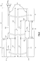
- Fig. 1 shows a partial longitudinal cross-sectional plan view and auxiliary cross-sectional views illustrating a first embodiment of a guide wire of the present invention.
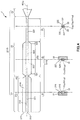
- Fig. 2 is an exploded plan view of a first core wire and a second core wire provided in the guide wire illustrated in Fig. 1 .
- a right side of Figs. 1 and 2 (the same applies to Figs. 3 to 7 ) is referred to as a "proximal end”
- a left side is referred to as a "distal end” for convenience of description.
- a longitudinal direction of the guide wire is shortened, a radial direction (a thickness direction) of the guide wire is schematically illustrated in an exaggerated manner, and a ratio between the longitudinal direction and the radial direction is different from an actual one in the drawings to facilitate an understanding of the invention.
- a guide wire 1 illustrated in Fig. 1 is a catheter guide wire used by being inserted into a lumen of a catheter including an endoscope.
- the guide wire 1 includes a wire main body 10 including a first core wire 2 and a second core wire 3, and a spiral coil 11 which covers a portion of a distal side of the wire main body 10.
- an overall length of the guide wire 1 is not particularly limited, when the guide wire 1 is used for a PCI, for example, the overall length is preferably 200 mm or more and 5000 mm or less, and more preferably 1000 mm or more and 3000 mm or less.
- the first core wire 2 is made of an elongated body having flexibility.
- the first core wire 2 has a first plate-shaped portion 21, a first linear portion 22, and a tapered portion 23, which are disposed in order from the distal side thereof. Note that it is preferable that, for example, the outer diameter of the portion of the first core wire 2 on the proximal side from the tapered portion 23 is constant.
- the first plate-shaped portion 21 is a portion having a plate shape.
- the first plate-shaped portion 21 is a flat plate in a natural state when no external force is applied.
- An overall length L 21 of the first plate-shaped portion 21 is not particularly limited, and is preferably, for example, 0.5 mm or more and 250.0 mm or less, and more preferably, 0.5 mm or more and 150 mm or less.
- the first plate-shaped portion 21 has a constant width portion 212 and a gradually decreasing width portion 213.
- the constant width portion 212 is a portion in which a width W 21 from the distal portion of the first plate-shaped portion 21 to a predetermined length is constant along a longitudinal direction of the wire.
- the gradually decreasing width portion 213 is a portion in which the width W 21 gradually decreases toward the proximal side at the proximal portion of the first plate-shaped portion 21.
- the width W 21 of the constant width portion 212 is not particularly limited, and is preferably, for example, 0.080 mm or more and 0.880 mm or less, and more preferably 0.100 mm or more and 0.350 mm or less. Note that a gradually decreasing width portion in which the width W 21 gradually decreases toward the distal side may be formed at the distal portion of the first plate-shaped portion 21.
- a thickness t 21 of the first plate-shaped portion 21 is constant along the longitudinal direction of the wire.
- the thickness t 21 is not particularly limited, and is preferably, for example, 0.015 mm or more and 0.070 mm or less. Note that although the thickness t 21 is constant along the longitudinal direction of the wire in this embodiment, the thickness t 21 is not limited thereto, and may, for example, gradually decrease toward the distal side.
- Such a first plate-shaped portion 21 can be bent and deformed into a desired shape together with a second linear portion 31 of the second core wire 3 overlapping the first plate-shaped portion 21, and can be used for shaping.
- the shaping is called "reshaping". By the shaping, it is possible to easily and reliably select the traveling direction of the guide wire 1 in the living body, and thus, the operability of the guide wire 1 is remarkably improved.
- the first linear portion 22 is provided continuously on the proximal side of the first plate-shaped portion 21.
- the first linear portion 22 is a portion having a linear shape that is thinner than the first plate-shaped portion 21.
- the overall length L 22 of the first linear portion 22 is longer than the overall length L 21 of the first plate-shaped portion 21.
- the cross-sectional shape of the first linear portion 22 is semicircular.
- a radius R 22 of the first linear portion 22 is constant along the longitudinal direction of the wire.
- the radius R 22 is not particularly limited, and is, for example, preferably the same as the thickness t 21 .
- the tapered portion 23 is provided continuously on the proximal side of the first linear portion 22.
- the tapered portion 23 is a portion in which an outer diameter ⁇ D 23 gradually decreases toward the distal side. Therefore, the rigidity of the first core wire 2 can be gradually reduced toward the distal side by the tapered portion 23, and for example, the followability of the guide wire 1 in the living body is improved.
- the second core wire 3 is an elongated body having flexibility which is configured separately from the first core wire 2, and is shorter than the first core wire 2.
- An overall length L 3 of the second core wire 3 is preferably equal to or shorter than the total sum of the overall length L 21 and the overall length L 22 of the first core wire 2.
- the distal portion of the second core wire 3 is fixed to the distal portion of the first core wire 2 via a fixing material 12, and the proximal portion thereof is fixed to the vicinity of a boundary portion between the first linear portion 22 and the tapered portion 23 of the first core wire 2 via a fixing material 13.
- each of the fixing material 12 and the fixing material 13 is made of a solder (brazing material), but it is not limited thereto, and for example, an adhesive agent may be used.
- a distal end 121 of the fixing material 12 is preferably rounded in order to prevent in vivo damage.
- the second core wire 3 has a second linear portion 31, a second plate-shaped portion 32, and a third linear portion 33 disposed in order from the distal side thereof.
- the second plate-shaped portion 32 has a plate shape, and is disposed to overlap the first linear portion 22 of the first core wire 2, that is, to be in contact therewith. Note that an overall length L 32 of the second plate-shaped portion 32 is the same as the overall length L 21 of the first plate-shaped portion 21 in the present embodiment.
- the second plate-shaped portion 32 is a portion which is bent and deformed into a desired shape together with the first linear portion 22 overlapping the second plate-shaped portion 32, and can be used for shaping in the same manner as the first plate-shaped portion 21.
- the first plate-shaped portion 21 and the second plate-shaped portion 32 of the guide wire 1, which are made of separate members, are portions responsible for shaping, respectively.
- the distal portion of the second core wire 3 is fixed to the first core wire 2 by the fixing material 12, and the proximal portion thereof is fixed to the first core wire 2 by the fixing material 13.
- an intermediate portion between the distal portion and the proximal portion of the second core wire 3 is not fixed to the first core wire 2, but is in a state of being in contact with the first core wire 2.
- the abutting resistance of the guide wire 1 can also be reduced.
- the "abutting resistance” is the hardness when the distal end of the guide wire 1 abuts against the blood vessel wall. Further, when the abutting resistance is high, there is a risk of piercing of the blood vessel wall with the guide wire 1. However, in contrast, as the abutting resistance is low, it is possible to prevent or suppress the risk.
- first core wire 2 and the second core wire 3 may be fixed to each other at arbitrary positions.
- the rigidity or the torque transmission performance of the guide wire 1 can be arbitrarily changed, by changing the place where the fixation is performed or the number of fixing points .
- the torque transmission performance is improved.
- fixation for example, there are fixation at the boundary portion between the first plate-shaped portion 21 and the second plate-shaped portion 32, fixation of the first plate-shaped portion 21 of the first core wire 2 and the second linear portion 31 of the second core wire 3, fixation of the first linear portion 22 of the first core wire 2 and the second plate-shaped portion 32 of the second core wire 3, and the like.
- fixation include a method of welding, a method of adhesion using solder (brazing filler metal) or an adhesive, and the like.
- the second plate-shaped portion 32 is a flat plate in a natural state before being shaped similar to the first plate-shaped portion 21. Further, a normal line N 21 of the first plate-shaped portion 21 and a normal line N 32 of the second plate-shaped portion 32 in the natural state are directed in the same direction. That is, the thickness direction of the first plate-shaped portion 21 and the thickness direction of the second plate-shaped portion 32 are directed in the same direction. Therefore, for example, the operation of superimposing the first core wire 2 and the second core wire 3 at the time of manufacturing the guide wire 1 becomes easy. Additionally, the two-dimensional shaping of the guide wire 1 can be easily performed.
- the shaping of the guide wire 1 is performed by bending the guide wire 1 in the normal direction of the first plate-shaped portion 21 or the second plate-shaped portion 32. Accordingly, when the normal line N 21 of the first plate-shaped portion 21 and the normal line N 32 of the second plate-shaped portion 32 are directed in the same direction, the bending directions of the first plate-shaped portion 21 and the second plate-shaped portion 32 can be made identical to each other. This is preferable in performing the two-dimensional shaping, for example, in a case where the first bent portion and the second bent portion are provided on the guide wire 1 to perform the shaping of the two-stage shape, since it is possible to provide the first bent portion and the second bent portion on the same plane including the long axis of the guide wire 1.
- the second plate-shaped portion 32 has a gradually decreasing width portion 321 having a width W 32 gradually decreasing toward the distal side formed at the distal portion, and a gradually decreasing width portion 323 having the width W 32 gradually decreasing toward the proximal side formed at the proximal portion.
- An intermediate portion between the gradually decreasing width portion 321 and the gradually decreasing width portion 323 is a constant width portion 322 in which the width W 32 is constant along the longitudinal direction of the wire.
- the width W 32 at the constant width portion 322 is the same as the width W 21 of the first plate-shaped portion 21, but it is not limited thereto, and the width W 32 may be greater than the width W 21 .
- a thickness t 32 of the second plate-shaped portion 32 is constant along the longitudinal direction of the wire, similarly to the thickness t 21 of the first plate-shaped portion 21.
- the thickness t 32 is the same as the thickness t 21 of the first plate-shaped portion 21, but it is not limited thereto, and the thickness t 32 may be thinner than the thickness t 21 .
- the thickness t 32 is not limited to being constant along the longitudinal direction of the wire, but may, for example, gradually decrease toward the distal direction.
- the overall length L 32 , the width W 32 and the thickness t 32 have the above-described sizes, and the overall length L 21 , the width W 21 and the thickness t 21 also have the above-mentioned sizes. By appropriately combining the respective sizes, it is possible to obtain the guide wire 1 having different degrees of shaping, depending on various operations.
- a distal end 324 (distal portion) of the second plate-shaped portion 32 is in contact with a proximal end 214 (proximal portion) of the adjacent first plate-shaped portion 21 on the distal side thereof in a plan view.
- the second plate-shaped portion 32 is in a state of being disposed on the distal side as much as possible.
- the first plate-shaped portion 21 and the second plate-shaped portion 32 form apparently continuous plate-shaped portions. Therefore, it is possible to secure a long shapeable region of the guide wire 1.
- the shaping is preferably performed at the distal portion of the guide wire 1. Therefore, when disposing the second plate-shaped portion 32 on the distal side as much as possible, a state preferable for shaping is obtained.
- the gradually decreasing width portion 321 formed on the distal side of the second plate-shaped portion 32 and the gradually decreasing width portion 213 formed on the proximal side of the first plate-shaped portion 21 can work together to reliably prevent the end portions of the second plate-shaped portion 32 and the first plate-shaped portion 21 from biting each other, for example, when the shaping is performed on the second plate-shaped portion 32. Therefore, it is possible to prevent the second plate-shaped portion 32 and the first plate-shaped portion 21 from being undesirably shaped.
- the length L 10 from the distal end 211 of the first plate-shaped portion 21 to the proximal end 325 of the second plate-shaped portion 32 along the longitudinal direction of the wire is preferably 0.5 mm or more and 250 mm or less, more preferably 0.5 mm or more and 100 mm or less, and even more preferably 0.5 mm or more and 50 mm or less. This contributes to achieving both the torque transmission performance and the shaping property.
- the second linear portion 31 is provided continuously on the distal side of the second plate-shaped portion 32.
- the second linear portion 31 is a portion having a linear shape that is thinner than the second plate-shaped portion 32.
- the second linear portion 31 is disposed to overlap the first plate-shaped portion 21, that is, to be in contact with the first plate-shaped portion 21, on the same side as the side on which the second plate-shaped portion 32 overlaps the first linear portion 22.
- the overall length L 31 of the second linear portion 31 is the same as the overall length L 21 of the first plate-shaped portion 21, but the present invention is not limited thereto, and the overall length L 31 may be, for example, shorter than the overall length L 21 .
- the overall length L 31 is shorter than the overall length L 21 , a distal end 313 of the second linear portion 31 is fixed in the middle of the first plate-shaped portion 21 in the longitudinal direction.
- the cross-sectional shape of the second linear portion 31 is semicircular. Therefore, the second linear portion 31 has a side surface 311 curved in a semicircular arc shape, and a flat side surface 312. By making the side surface 312 among the side surface 311 and the side surface 312 face the first plate-shaped portion 21, the first plate-shaped portion 21 and the second linear portion 31 enter a state of stably overlapping each other.
- a radius R 31 of the second linear portion 31 is constant along the longitudinal direction of the wire.
- the radius R 31 is not particularly limited, and may be, for example, the same as the thickness t 32 .
- the third linear portion 33 is provided continuously on the proximal side of the second plate-shaped portion 32.
- the third linear portion 33 is a portion having a linear shape that is thinner than the second plate-shaped portion 32.
- the third linear portion 33 is disposed to overlap the first linear portion 22 together with the second plate-shaped portion 32, that is, to be in contact with the first linear portion 22.
- the second plate-shaped portion 32 enters a state of being separated from the fixing material 13. Therefore, it is possible to prevent or suppress the influence of the fixation by the fixing material 13 on the second plate-shaped portion 32 at the time of shaping the second plate-shaped portion 32.
- the third linear portion 33 contributes to reliably transmitting the torque, which is applied from the proximal side of the guide wire 1, to the second core wire 3. Furthermore, the torque applied from the proximal side of the guide wire 1 is transmitted to the first core wire 2 and the second core wire 3 without biasing since the third linear portion 33 is disposed to overlap the first linear portion 22.
- the cross-sectional shape of the third linear portion 33 is semicircular. Accordingly, the third linear portion 33 has a side surface 331 curved in a semicircular arc shape, and a flat side surface 332. Further, by making the side surface 332 among the side surface 331 and the side surface 332 face the side surface 222 of the first linear portion 22, the third linear portion 33 and the first linear portion 22 enter a state of stably overlapping each other.
- a radius R 33 of the third linear portion 33 is constant along the longitudinal direction of the wire.
- the radius R 33 is not particularly limited, and is preferably, for example, the same as the radius R 22 .
- the cross-sectional shape of the first linear portion 22 and the cross-sectional shape of the second linear portion 31 each have a semicircular shape.
- a center O 22 of the semicircle in the first linear portion 22 and a center O 31 of the semicircle in the second linear portion 31 are in a coaxial state positioned on the same one axis AX 10 along the longitudinal direction of the wire. In other words, the center O 22 and the center O 31 overlap each other when viewed from the distal side in the natural state.
- a center O 33 of the semicircle in the third linear portion 33 and the center O 22 of the semicircle in the first linear portion 22 are also in a coaxial state positioned on the axis AX 10 .
- a "circle" is formed by the cross-sectional shape of the third linear portion 33 and the cross-sectional shape of the first linear portion 22.
- the guide wire 1 described above can achieve both excellent torque transmission performance and excellent shaping property.
- the wire main body 10 of the guide wire 1 is formed by making the first core wire 2 and the second core wire 3 overlap each other, the breaking strength is improved.
- the constituent materials of the first core wire 2 and the second core wire 3 as described above are not particularly limited, and it is possible to use various metal materials such as alloys exhibiting pseudoelasticity including superelastic alloys, such as stainless steel, piano wire, cobalt type alloy, and nickel titanium alloy.
- superelastic alloy such as stainless steel, piano wire, cobalt type alloy, and nickel titanium alloy.
- a treatment for eliminating superelasticity of a portion relating to shaping may be performed in order to improve the shaping property.
- the shaping portion means the first plate-shaped portion 21 and the first linear portion 22 of the first core wire 2 and the entire second core wire 3, that is, from the second linear portion 31 of the second core wire 3 to the third linear portion 33.
- first core wire 2 and the second core wire 3 may be made of different materials, but it is preferable that they are made of the same or the same kind of material.
- the outer diameters of the linear portions of the first core wire 2 and the second core wire 3 are not particularly limited and can be outer diameters suitable as a guide wire.
- the outer diameters of the linear portions of the first core wire 2 and the second core wire 3 are, for example, 40 ⁇ m to 360 ⁇ m.
- the coil 11 covers the first plate-shaped portion 21 and the first linear portion 22 of the first core wire 2, and covers the entire second core wire 3, that is, from the second linear portion 31 of the second core wire 3 to the third linear portion 33.
- the coil 11 is fixed to the first core wire 2 via the fixing material 12 and the fixing material 13.
- the coil 11 is formed by winding an element wire 111 around the wire main body 10, and the element wires 111 adjacent to each other in the longitudinal direction of the wire are in contact with each other in a natural state, namely, a so-called close winding state.
- the guide wire 1 is not limited to such a close winding configuration, and may have a rough winding portion in which the adjacent element wires 111 are spaced apart from each other.
- the second plate-shaped portion 32 is spaced apart from the coil 11, regardless of whether or not the shaping is performed. Therefore, the degree of freedom of shaping in the second plate-shaped portion 32 can be sufficiently secured.
- the guide wire 1 it is preferable that at least the outer peripheral portion of the coil 11 is coated with a hydrophilic material. As a result, the hydrophilic material is wetted to produce lubricity, the sliding resistance of the guide wire 1 is reduced, and the slidability is improved. Therefore, the operability of the guide wire 1 is improved.
- hydrophilic material for example, it is possible to use a cellulose-based polymer substance, a polyethylene oxide-based polymer substance, a maleic anhydride-based polymer substance (for example, a maleic anhydride copolymer such as methyl vinyl ether-maleic anhydride copolymer), an acrylamide-based polymer material (for example, a polyacrylamide, a polyglycidyl methacrylate-dimethyl acrylamide (PGMA-DMAA) block copolymer), water-soluble nylon, polyvinyl alcohol, polyvinyl pyrrolidone, and the like.
- a cellulose-based polymer substance for example, a polyethylene oxide-based polymer substance, a maleic anhydride-based polymer substance (for example, a maleic anhydride copolymer such as methyl vinyl ether-maleic anhydride copolymer), an acrylamide-based polymer material (for example, a polyacrylamide, a polyglycidyl meth
- Fig. 3 shows a plan view and auxiliary cross-sectional views of a first core wire and a second core wire included in a guide wire (the second embodiment) of the present invention.
- the present embodiment is the same as the first embodiment except that it has a positioning portion that maintains the coaxial state.
- the cross-sectional shape of the portion of the first linear portion 22 overlapping the second plate-shaped portion 32 is circular.
- the cross-sectional shape of the second linear portion 31 is also circular. It is more preferable that an outer diameter ⁇ D 22 of the first linear portion 22 having a circular shape and an outer diameter ⁇ D 31 of the second linear portion 31 have the same size.
- a first groove 215 is formed along the longitudinal direction of the wire.
- the first groove 215 is formed by bending and plastically deforming the first plate-shaped portion 21 by, for example, a pressing machine. Then, the second linear portion 31 can be inserted into the first groove 215.
- a second groove 326 is formed in the second-plate shaped portion 32 along the longitudinal direction of the wire. Like the first groove 215, the second groove 326 is also formed by bending and plastically deforming the second plate-shaped portion 32 by, for example, a pressing machine. The first linear portion 22 can then be inserted into the second groove 326.
- the center O 22 of the circle in the first linear portion 22 and the center O 31 of the circle in the second linear portion 31 are in a coaxial state positioned on the axis AX 10 , and the coaxial state can be reliably maintained. As a result, it is possible to reliably improve torque transmission performance.
- the first groove 215 and the second groove 326 function as positioning portions that maintain the coaxial state.
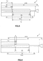
- Fig. 4 depicts a plan view and auxiliary cross-sectional views of a first core wire and a second core wire included in a guide wire (a third embodiment) of the present invention.
- This embodiment is the same as the first embodiment except that the method of forming the first groove and the second groove is different.
- the first groove 215 is formed by cutting a surface 216 of the first plate-shaped portion 21 facing the second linear portion 31 side by, for example, a cutting machine.
- the first groove 215 can be provided as a groove having a size large enough to fit the second linear portion 31, the second linear portion 31 is prevented from being detached from the first groove 215.
- the second groove 326 is formed by cutting a surface 327 of the second plate-shaped portion 32 facing the first linear portion 22 side by, for example, a cutting machine. Accordingly, since the second groove 326 can be provided as a groove having a size large enough to fit the first linear portion 22, the first linear portion 22 is prevented from being detached from the second groove 326.
- Fig. 5 is a plan view of a first core wire and a second core wire of a guide wire (a fourth embodiment) of the present invention.
- This embodiment is the same as the first embodiment except that a magnitude relation between the overall length of the first plate-shaped portion and the overall length of the second plate-shaped portion is different.
- the overall length L 32 of the second plate-shaped portion 32 is longer than the overall length L 21 of the first plate-shaped portion 21. This makes it easier to perform the shaping on the second plate-shaped portion 32.
- Fig. 6 is a plan view of a first core wire and a second core wire of a guide wire (a fifth embodiment) of the present invention.
- This embodiment is the same as the first embodiment except that a positional relation between the first plate-shaped portion and the second plate-shaped portion is different.
- an overlapping portion 4 is formed in which a proximal portion of the first plate-shaped portion 21 and the distal portion of a second plate-shaped portion 32 overlap in a plan view.
- torque is smoothly transmitted from the second plate-shaped portion 32 to the first plate-shaped portion 21. Therefore, the torque transmission performance is improved.
- Fig. 7 is an exploded plan view of a first core wire and a second core wire of a guide wire (a sixth embodiment) of the present invention.
- This embodiment is the same as the first embodiment except that the shapes of the first core wire and the second core wire are different from each other.
- a width W 222 of the side surface 222 of the first linear portion 22 of the first core wire 2 decreases stepwise toward the distal side.
- a width W 331 of the side surface 331 also decreases stepwise toward the distal side, corresponding to the shape of the first linear portion 22. Note that it is preferable that the cross-sectional shape of the first linear portion 22 and the cross-sectional shape of the third linear portion 33 together form a "circle".
- a width W 311 of the side surface 311 of the second linear portion 31 of the second core wire 3 also decreases stepwise toward the distal side.
- the guide wire 1 thus gradually decreases in rigidity toward the distal side as a whole by having the shape as described above.
- the guide wire 1 has, for example, good flexibility at the distal portion, and the followability to the blood vessel or the like and safety are improved.
- width W 222 , the width W 311 , and the width W 331 decrease stepwise toward the distal side as described above, and the number of stages is one in the illustrated configuration, but is not limited to this and may be plural stages.
- Each of the width W 222 , the width W 311 , and the width W 331 may, for example, continuously decrease toward the distal side, in addition to the stepwise decrease toward the distal side.
- guide wire of the present invention has been described with reference to the embodiment illustrated in the drawings, the present invention is not limited thereto, and each part constituting the guide wire may be substituted for any configuration capable of exerting the same function. Also, arbitrary components may be added.
- the guide wire of the present invention may be a combination of arbitrary two or more configurations (features) among the above embodiments.
- the number of the second core wires is one in each of the above embodiments, it is not limited thereto, and may be, for example, plural.
- the guide wire can be one in which the first core wire is disposed between the two second core wires.
- a magnitude relation between the overall length of the first core wire and the overall length of the second core wire is set such that the overall length of the first core wire is longer than the overall length of the second core wire in each of the above embodiments, it is not limited thereto, and the overall length of the second core wire may be longer than the overall length of the first core wire.
- the gradually decreasing width portion can be omitted.
- the third linear portion can be omitted.
- the cross-sectional shape of the portion of the first linear portion of the first core wire overlapping the third linear portion is circular.
- the guide wire of the present invention is a guide wire including a flexible first core wire, and a flexible second core wire configured separately from the first core wire.
- the first core wire has a first plate-shaped portion having a plate shape, and a first linear portion provided continuously to the proximal side of the first plate-shaped portion and having a linear shape thinner than the first plate-shaped portion.
- the second core wire has a second plate-shaped portion having a plate shape and disposed to overlap the first linear portion, and a second linear portion that is provided continuously on the distal side of the second plate-shaped portion, has a linear shape thinner than the second plate-shaped portion, and is disposed to overlap the first plate-shaped portion. Therefore, it is possible to achieve excellent compatibility between the torque transmission performance and the shaping property. Therefore, the guide wire of the present invention has industrial applicability.
Landscapes
- Health & Medical Sciences (AREA)
- Life Sciences & Earth Sciences (AREA)
- Biophysics (AREA)
- Pulmonology (AREA)
- Engineering & Computer Science (AREA)
- Anesthesiology (AREA)
- Biomedical Technology (AREA)
- Heart & Thoracic Surgery (AREA)
- Hematology (AREA)
- Animal Behavior & Ethology (AREA)
- General Health & Medical Sciences (AREA)
- Public Health (AREA)
- Veterinary Medicine (AREA)
- Media Introduction/Drainage Providing Device (AREA)
Applications Claiming Priority (2)
| Application Number | Priority Date | Filing Date | Title |
|---|---|---|---|
| JP2016159989 | 2016-08-17 | ||
| PCT/JP2017/024562 WO2018034072A1 (fr) | 2016-08-17 | 2017-07-04 | Fil-guide |
Publications (3)
| Publication Number | Publication Date |
|---|---|
| EP3501588A1 true EP3501588A1 (fr) | 2019-06-26 |
| EP3501588A4 EP3501588A4 (fr) | 2020-04-29 |
| EP3501588B1 EP3501588B1 (fr) | 2021-06-16 |
Family
ID=61196688
Family Applications (1)
| Application Number | Title | Priority Date | Filing Date |
|---|---|---|---|
| EP17841300.1A Active EP3501588B1 (fr) | 2016-08-17 | 2017-07-04 | Fil-guide |
Country Status (5)
| Country | Link |
|---|---|
| US (1) | US11260205B2 (fr) |
| EP (1) | EP3501588B1 (fr) |
| JP (1) | JP6894905B2 (fr) |
| CN (1) | CN109069804B (fr) |
| WO (1) | WO2018034072A1 (fr) |
Families Citing this family (1)
| Publication number | Priority date | Publication date | Assignee | Title |
|---|---|---|---|---|
| JP7514797B2 (ja) | 2021-05-25 | 2024-07-11 | 朝日インテック株式会社 | ガイドワイヤ |
Family Cites Families (33)
| Publication number | Priority date | Publication date | Assignee | Title |
|---|---|---|---|---|
| US4830023A (en) * | 1987-11-27 | 1989-05-16 | Medi-Tech, Incorporated | Medical guidewire |
| US4934380A (en) | 1987-11-27 | 1990-06-19 | Boston Scientific Corporation | Medical guidewire |
| US4796642A (en) * | 1987-12-28 | 1989-01-10 | Cordis Leads, Inc. | Pacing lead stylet |
| US5147317A (en) * | 1990-06-04 | 1992-09-15 | C.R. Bard, Inc. | Low friction varied radiopacity guidewire |
| JPH0683726B2 (ja) * | 1990-10-12 | 1994-10-26 | 日本精線株式会社 | カテーテル用ガイドワイヤ |
| US5299580A (en) * | 1992-10-09 | 1994-04-05 | Scimed Life Systems, Inc. | Guidewire with safety ribbon with substantially axially symmetric flexibility |
| US5358479A (en) * | 1993-12-06 | 1994-10-25 | Electro-Catheter Corporation | Multiform twistable tip deflectable catheter |
| US5824031A (en) | 1996-02-28 | 1998-10-20 | Cardio Source | Apparatus and method for deflecting a tip of a lead or catheter |
| US6132390A (en) * | 1996-02-28 | 2000-10-17 | Eupalamus Llc | Handle for manipulation of a stylet used for deflecting a tip of a lead or catheter |
| US6890329B2 (en) * | 1999-06-15 | 2005-05-10 | Cryocath Technologies Inc. | Defined deflection structure |
| US6290656B1 (en) * | 1999-12-30 | 2001-09-18 | Advanced Cardiovascular Systems, Inc. | Guide wire with damped force vibration mechanism |
| US6761696B1 (en) * | 2001-11-13 | 2004-07-13 | Advanced Cardiovascular Systems, Inc. | Guide wire with a non-rectangular shaping member |
| JP4188663B2 (ja) * | 2002-11-06 | 2008-11-26 | 株式会社パイオラックスメディカルデバイス | ガイドワイヤ |
| WO2004056415A1 (fr) * | 2002-12-20 | 2004-07-08 | Brivant Research & Development Limited | Fil-guide utilise avec un catheter |
| US7998090B2 (en) * | 2004-08-31 | 2011-08-16 | Abbott Cardiovascular Systems Inc. | Guide wire with core having welded wire segments |
| CN100518851C (zh) * | 2005-03-02 | 2009-07-29 | 泰尔茂株式会社 | 导丝 |
| JP2006271955A (ja) * | 2005-03-02 | 2006-10-12 | Terumo Corp | ガイドワイヤ |
| US9974930B2 (en) * | 2005-03-24 | 2018-05-22 | Brivant Research & Development Limited | Guide wire for use in re-canalising a vascular occlusion in a human or animal subject |
| CN102688551A (zh) | 2006-03-06 | 2012-09-26 | 泰尔茂株式会社 | 导丝 |
| US20070244413A1 (en) * | 2006-04-12 | 2007-10-18 | Medtronic Vascular, Inc. | Medical guidewire tip construction |
| CA2673557C (fr) * | 2006-12-22 | 2013-02-12 | Wilson-Cook Medical Inc. | Guide-fil capable de dedoublement longitudinal |
| JP2008237253A (ja) | 2007-03-23 | 2008-10-09 | Terumo Corp | ガイドワイヤ |
| US8360995B2 (en) * | 2007-09-18 | 2013-01-29 | Cook Medical Technologies Llc | Wire guide |
| US8376961B2 (en) * | 2008-04-07 | 2013-02-19 | Boston Scientific Scimed, Inc. | Micromachined composite guidewire structure with anisotropic bending properties |
| US20100087780A1 (en) * | 2008-10-03 | 2010-04-08 | Cook Incorporated | Wire Guide having Variable Flexibility and Method of Use Thereof |
| JP5013547B2 (ja) * | 2009-06-16 | 2012-08-29 | 朝日インテック株式会社 | 医療用ガイドワイヤ |
| JP5382953B2 (ja) | 2011-01-28 | 2014-01-08 | 朝日インテック株式会社 | ガイドワイヤ |
| JP2012200291A (ja) | 2011-03-23 | 2012-10-22 | Asahi Intecc Co Ltd | ガイドワイヤ |
| JP2013094343A (ja) | 2011-10-31 | 2013-05-20 | Asahi Intecc Co Ltd | ガイドワイヤ |
| JP6294211B2 (ja) | 2014-02-24 | 2018-03-14 | 朝日インテック株式会社 | ガイドワイヤ |
| EP3171764B1 (fr) * | 2014-07-22 | 2023-06-07 | Koninklijke Philips N.V. | Dispositifs intravasculaires, systèmes et procédés comprenant un fil central à sections aplaties multiples |
| JP6302810B2 (ja) * | 2014-09-25 | 2018-03-28 | テルモ株式会社 | ガイドワイヤ |
| JP6560686B2 (ja) | 2014-09-26 | 2019-08-14 | テルモ株式会社 | ガイドワイヤ |
-
2017
- 2017-07-04 WO PCT/JP2017/024562 patent/WO2018034072A1/fr active Application Filing
- 2017-07-04 EP EP17841300.1A patent/EP3501588B1/fr active Active
- 2017-07-04 JP JP2018534292A patent/JP6894905B2/ja active Active
- 2017-07-04 CN CN201780026227.5A patent/CN109069804B/zh active Active
-
2018
- 2018-10-09 US US16/155,374 patent/US11260205B2/en active Active
Also Published As
| Publication number | Publication date |
|---|---|
| CN109069804A (zh) | 2018-12-21 |
| WO2018034072A1 (fr) | 2018-02-22 |
| CN109069804B (zh) | 2021-03-09 |
| EP3501588B1 (fr) | 2021-06-16 |
| JP6894905B2 (ja) | 2021-06-30 |
| US20190046774A1 (en) | 2019-02-14 |
| JPWO2018034072A1 (ja) | 2019-06-13 |
| EP3501588A4 (fr) | 2020-04-29 |
| US11260205B2 (en) | 2022-03-01 |
Similar Documents
| Publication | Publication Date | Title |
|---|---|---|
| EP2417999B1 (fr) | Fil-guide courbé muni d'un élément de maintien de courbure | |
| EP2962718B1 (fr) | Fil-guide | |
| EP2689795A1 (fr) | Fil-guide | |
| WO2016047499A1 (fr) | Fil-guide | |
| JP5392792B2 (ja) | ガイドワイヤ | |
| JP2011251046A (ja) | ガイドワイヤ | |
| EP2937109A1 (fr) | Fil-guide | |
| EP2481441A1 (fr) | Fil-guide | |
| JP5490152B2 (ja) | ガイドワイヤ | |
| EP2921197A1 (fr) | Fil guide | |
| JP2011177392A (ja) | ガイドワイヤ | |
| EP3501588A1 (fr) | Fil-guide | |
| WO2018062155A1 (fr) | Fil-guide | |
| JP7546454B2 (ja) | ガイドワイヤ | |
| JP2018108119A (ja) | ガイドワイヤおよび医療用コイル | |
| JP2013208351A (ja) | ガイドワイヤ | |
| JP6155199B2 (ja) | ガイドワイヤ | |
| JPWO2016047555A1 (ja) | ガイドワイヤおよびガイドワイヤの製造方法 | |
| JP2018027221A (ja) | ガイドワイヤ | |
| JP2003334253A (ja) | ガイドワイヤー | |
| WO2014162389A1 (fr) | Fil guide | |
| JP2003126265A (ja) | ガイドワイヤー | |
| JP2016067385A (ja) | ガイドワイヤおよびガイドワイヤの製造方法 | |
| JP2004065794A (ja) | ガイドワイヤ | |
| JP2013154070A (ja) | ガイドワイヤ |
Legal Events
| Date | Code | Title | Description |
|---|---|---|---|
| STAA | Information on the status of an ep patent application or granted ep patent |
Free format text: STATUS: THE INTERNATIONAL PUBLICATION HAS BEEN MADE |
|
| PUAI | Public reference made under article 153(3) epc to a published international application that has entered the european phase |
Free format text: ORIGINAL CODE: 0009012 |
|
| STAA | Information on the status of an ep patent application or granted ep patent |
Free format text: STATUS: REQUEST FOR EXAMINATION WAS MADE |
|
| 17P | Request for examination filed |
Effective date: 20190204 |
|
| AK | Designated contracting states |
Kind code of ref document: A1 Designated state(s): AL AT BE BG CH CY CZ DE DK EE ES FI FR GB GR HR HU IE IS IT LI LT LU LV MC MK MT NL NO PL PT RO RS SE SI SK SM TR |
|
| AX | Request for extension of the european patent |
Extension state: BA ME |
|
| DAV | Request for validation of the european patent (deleted) | ||
| DAX | Request for extension of the european patent (deleted) | ||
| A4 | Supplementary search report drawn up and despatched |
Effective date: 20200326 |
|
| RIC1 | Information provided on ipc code assigned before grant |
Ipc: A61M 25/09 20060101AFI20200321BHEP |
|
| GRAP | Despatch of communication of intention to grant a patent |
Free format text: ORIGINAL CODE: EPIDOSNIGR1 |
|
| STAA | Information on the status of an ep patent application or granted ep patent |
Free format text: STATUS: GRANT OF PATENT IS INTENDED |
|
| GRAJ | Information related to disapproval of communication of intention to grant by the applicant or resumption of examination proceedings by the epo deleted |
Free format text: ORIGINAL CODE: EPIDOSDIGR1 |
|
| STAA | Information on the status of an ep patent application or granted ep patent |
Free format text: STATUS: REQUEST FOR EXAMINATION WAS MADE |
|
| INTG | Intention to grant announced |
Effective date: 20201123 |
|
| INTC | Intention to grant announced (deleted) | ||
| GRAP | Despatch of communication of intention to grant a patent |
Free format text: ORIGINAL CODE: EPIDOSNIGR1 |
|
| STAA | Information on the status of an ep patent application or granted ep patent |
Free format text: STATUS: GRANT OF PATENT IS INTENDED |
|
| INTG | Intention to grant announced |
Effective date: 20210212 |
|
| GRAS | Grant fee paid |
Free format text: ORIGINAL CODE: EPIDOSNIGR3 |
|
| GRAA | (expected) grant |
Free format text: ORIGINAL CODE: 0009210 |
|
| STAA | Information on the status of an ep patent application or granted ep patent |
Free format text: STATUS: THE PATENT HAS BEEN GRANTED |
|
| AK | Designated contracting states |
Kind code of ref document: B1 Designated state(s): AL AT BE BG CH CY CZ DE DK EE ES FI FR GB GR HR HU IE IS IT LI LT LU LV MC MK MT NL NO PL PT RO RS SE SI SK SM TR |
|
| REG | Reference to a national code |
Ref country code: GB Ref legal event code: FG4D |
|
| REG | Reference to a national code |
Ref country code: CH Ref legal event code: EP |
|
| REG | Reference to a national code |
Ref country code: DE Ref legal event code: R096 Ref document number: 602017040526 Country of ref document: DE |
|
| REG | Reference to a national code |
Ref country code: AT Ref legal event code: REF Ref document number: 1401794 Country of ref document: AT Kind code of ref document: T Effective date: 20210715 |
|
| REG | Reference to a national code |
Ref country code: IE Ref legal event code: FG4D |
|
| REG | Reference to a national code |
Ref country code: LT Ref legal event code: MG9D |
|
| PG25 | Lapsed in a contracting state [announced via postgrant information from national office to epo] |
Ref country code: FI Free format text: LAPSE BECAUSE OF FAILURE TO SUBMIT A TRANSLATION OF THE DESCRIPTION OR TO PAY THE FEE WITHIN THE PRESCRIBED TIME-LIMIT Effective date: 20210616 Ref country code: LT Free format text: LAPSE BECAUSE OF FAILURE TO SUBMIT A TRANSLATION OF THE DESCRIPTION OR TO PAY THE FEE WITHIN THE PRESCRIBED TIME-LIMIT Effective date: 20210616 Ref country code: HR Free format text: LAPSE BECAUSE OF FAILURE TO SUBMIT A TRANSLATION OF THE DESCRIPTION OR TO PAY THE FEE WITHIN THE PRESCRIBED TIME-LIMIT Effective date: 20210616 Ref country code: BG Free format text: LAPSE BECAUSE OF FAILURE TO SUBMIT A TRANSLATION OF THE DESCRIPTION OR TO PAY THE FEE WITHIN THE PRESCRIBED TIME-LIMIT Effective date: 20210916 |
|
| REG | Reference to a national code |
Ref country code: AT Ref legal event code: MK05 Ref document number: 1401794 Country of ref document: AT Kind code of ref document: T Effective date: 20210616 |
|
| REG | Reference to a national code |
Ref country code: NL Ref legal event code: MP Effective date: 20210616 |
|
| PG25 | Lapsed in a contracting state [announced via postgrant information from national office to epo] |
Ref country code: GR Free format text: LAPSE BECAUSE OF FAILURE TO SUBMIT A TRANSLATION OF THE DESCRIPTION OR TO PAY THE FEE WITHIN THE PRESCRIBED TIME-LIMIT Effective date: 20210917 Ref country code: LV Free format text: LAPSE BECAUSE OF FAILURE TO SUBMIT A TRANSLATION OF THE DESCRIPTION OR TO PAY THE FEE WITHIN THE PRESCRIBED TIME-LIMIT Effective date: 20210616 Ref country code: NO Free format text: LAPSE BECAUSE OF FAILURE TO SUBMIT A TRANSLATION OF THE DESCRIPTION OR TO PAY THE FEE WITHIN THE PRESCRIBED TIME-LIMIT Effective date: 20210916 Ref country code: RS Free format text: LAPSE BECAUSE OF FAILURE TO SUBMIT A TRANSLATION OF THE DESCRIPTION OR TO PAY THE FEE WITHIN THE PRESCRIBED TIME-LIMIT Effective date: 20210616 Ref country code: SE Free format text: LAPSE BECAUSE OF FAILURE TO SUBMIT A TRANSLATION OF THE DESCRIPTION OR TO PAY THE FEE WITHIN THE PRESCRIBED TIME-LIMIT Effective date: 20210616 |
|
| PG25 | Lapsed in a contracting state [announced via postgrant information from national office to epo] |
Ref country code: SM Free format text: LAPSE BECAUSE OF FAILURE TO SUBMIT A TRANSLATION OF THE DESCRIPTION OR TO PAY THE FEE WITHIN THE PRESCRIBED TIME-LIMIT Effective date: 20210616 Ref country code: SK Free format text: LAPSE BECAUSE OF FAILURE TO SUBMIT A TRANSLATION OF THE DESCRIPTION OR TO PAY THE FEE WITHIN THE PRESCRIBED TIME-LIMIT Effective date: 20210616 Ref country code: ES Free format text: LAPSE BECAUSE OF FAILURE TO SUBMIT A TRANSLATION OF THE DESCRIPTION OR TO PAY THE FEE WITHIN THE PRESCRIBED TIME-LIMIT Effective date: 20210616 Ref country code: EE Free format text: LAPSE BECAUSE OF FAILURE TO SUBMIT A TRANSLATION OF THE DESCRIPTION OR TO PAY THE FEE WITHIN THE PRESCRIBED TIME-LIMIT Effective date: 20210616 Ref country code: RO Free format text: LAPSE BECAUSE OF FAILURE TO SUBMIT A TRANSLATION OF THE DESCRIPTION OR TO PAY THE FEE WITHIN THE PRESCRIBED TIME-LIMIT Effective date: 20210616 Ref country code: PT Free format text: LAPSE BECAUSE OF FAILURE TO SUBMIT A TRANSLATION OF THE DESCRIPTION OR TO PAY THE FEE WITHIN THE PRESCRIBED TIME-LIMIT Effective date: 20211018 Ref country code: NL Free format text: LAPSE BECAUSE OF FAILURE TO SUBMIT A TRANSLATION OF THE DESCRIPTION OR TO PAY THE FEE WITHIN THE PRESCRIBED TIME-LIMIT Effective date: 20210616 Ref country code: CZ Free format text: LAPSE BECAUSE OF FAILURE TO SUBMIT A TRANSLATION OF THE DESCRIPTION OR TO PAY THE FEE WITHIN THE PRESCRIBED TIME-LIMIT Effective date: 20210616 Ref country code: AT Free format text: LAPSE BECAUSE OF FAILURE TO SUBMIT A TRANSLATION OF THE DESCRIPTION OR TO PAY THE FEE WITHIN THE PRESCRIBED TIME-LIMIT Effective date: 20210616 |
|
| PG25 | Lapsed in a contracting state [announced via postgrant information from national office to epo] |
Ref country code: PL Free format text: LAPSE BECAUSE OF FAILURE TO SUBMIT A TRANSLATION OF THE DESCRIPTION OR TO PAY THE FEE WITHIN THE PRESCRIBED TIME-LIMIT Effective date: 20210616 |
|
| REG | Reference to a national code |
Ref country code: CH Ref legal event code: PL |
|
| REG | Reference to a national code |
Ref country code: DE Ref legal event code: R097 Ref document number: 602017040526 Country of ref document: DE |
|
| PG25 | Lapsed in a contracting state [announced via postgrant information from national office to epo] |
Ref country code: MC Free format text: LAPSE BECAUSE OF FAILURE TO SUBMIT A TRANSLATION OF THE DESCRIPTION OR TO PAY THE FEE WITHIN THE PRESCRIBED TIME-LIMIT Effective date: 20210616 |
|
| REG | Reference to a national code |
Ref country code: BE Ref legal event code: MM Effective date: 20210731 |
|
| PLBE | No opposition filed within time limit |
Free format text: ORIGINAL CODE: 0009261 |
|
| STAA | Information on the status of an ep patent application or granted ep patent |
Free format text: STATUS: NO OPPOSITION FILED WITHIN TIME LIMIT |
|
| PG25 | Lapsed in a contracting state [announced via postgrant information from national office to epo] |
Ref country code: LI Free format text: LAPSE BECAUSE OF NON-PAYMENT OF DUE FEES Effective date: 20210731 Ref country code: DK Free format text: LAPSE BECAUSE OF FAILURE TO SUBMIT A TRANSLATION OF THE DESCRIPTION OR TO PAY THE FEE WITHIN THE PRESCRIBED TIME-LIMIT Effective date: 20210616 Ref country code: CH Free format text: LAPSE BECAUSE OF NON-PAYMENT OF DUE FEES Effective date: 20210731 |
|
| 26N | No opposition filed |
Effective date: 20220317 |
|
| GBPC | Gb: european patent ceased through non-payment of renewal fee |
Effective date: 20210916 |
|
| PG25 | Lapsed in a contracting state [announced via postgrant information from national office to epo] |
Ref country code: LU Free format text: LAPSE BECAUSE OF NON-PAYMENT OF DUE FEES Effective date: 20210704 Ref country code: AL Free format text: LAPSE BECAUSE OF FAILURE TO SUBMIT A TRANSLATION OF THE DESCRIPTION OR TO PAY THE FEE WITHIN THE PRESCRIBED TIME-LIMIT Effective date: 20210616 |
|
| PG25 | Lapsed in a contracting state [announced via postgrant information from national office to epo] |
Ref country code: IT Free format text: LAPSE BECAUSE OF FAILURE TO SUBMIT A TRANSLATION OF THE DESCRIPTION OR TO PAY THE FEE WITHIN THE PRESCRIBED TIME-LIMIT Effective date: 20210616 Ref country code: IE Free format text: LAPSE BECAUSE OF NON-PAYMENT OF DUE FEES Effective date: 20210704 Ref country code: GB Free format text: LAPSE BECAUSE OF NON-PAYMENT OF DUE FEES Effective date: 20210916 Ref country code: FR Free format text: LAPSE BECAUSE OF NON-PAYMENT OF DUE FEES Effective date: 20210816 Ref country code: BE Free format text: LAPSE BECAUSE OF NON-PAYMENT OF DUE FEES Effective date: 20210731 |
|
| PG25 | Lapsed in a contracting state [announced via postgrant information from national office to epo] |
Ref country code: CY Free format text: LAPSE BECAUSE OF FAILURE TO SUBMIT A TRANSLATION OF THE DESCRIPTION OR TO PAY THE FEE WITHIN THE PRESCRIBED TIME-LIMIT Effective date: 20210616 |
|
| PG25 | Lapsed in a contracting state [announced via postgrant information from national office to epo] |
Ref country code: HU Free format text: LAPSE BECAUSE OF FAILURE TO SUBMIT A TRANSLATION OF THE DESCRIPTION OR TO PAY THE FEE WITHIN THE PRESCRIBED TIME-LIMIT; INVALID AB INITIO Effective date: 20170704 |
|
| PGFP | Annual fee paid to national office [announced via postgrant information from national office to epo] |
Ref country code: DE Payment date: 20230531 Year of fee payment: 7 |
|
| PG25 | Lapsed in a contracting state [announced via postgrant information from national office to epo] |
Ref country code: MK Free format text: LAPSE BECAUSE OF FAILURE TO SUBMIT A TRANSLATION OF THE DESCRIPTION OR TO PAY THE FEE WITHIN THE PRESCRIBED TIME-LIMIT Effective date: 20210616 |
|
| PG25 | Lapsed in a contracting state [announced via postgrant information from national office to epo] |
Ref country code: TR Free format text: LAPSE BECAUSE OF FAILURE TO SUBMIT A TRANSLATION OF THE DESCRIPTION OR TO PAY THE FEE WITHIN THE PRESCRIBED TIME-LIMIT Effective date: 20210616 |
|
| PG25 | Lapsed in a contracting state [announced via postgrant information from national office to epo] |
Ref country code: MT Free format text: LAPSE BECAUSE OF FAILURE TO SUBMIT A TRANSLATION OF THE DESCRIPTION OR TO PAY THE FEE WITHIN THE PRESCRIBED TIME-LIMIT Effective date: 20210616 |