EP3500715B1 - Vorrichtung zur spannung eines bowdenzugs eines seilzug-fensterhebers - Google Patents
Vorrichtung zur spannung eines bowdenzugs eines seilzug-fensterhebers Download PDFInfo
- Publication number
- EP3500715B1 EP3500715B1 EP17761022.7A EP17761022A EP3500715B1 EP 3500715 B1 EP3500715 B1 EP 3500715B1 EP 17761022 A EP17761022 A EP 17761022A EP 3500715 B1 EP3500715 B1 EP 3500715B1
- Authority
- EP
- European Patent Office
- Prior art keywords
- cable
- stops
- pair
- spring
- damping element
- Prior art date
- Legal status (The legal status is an assumption and is not a legal conclusion. Google has not performed a legal analysis and makes no representation as to the accuracy of the status listed.)
- Active
Links
Images


Classifications
-
- E—FIXED CONSTRUCTIONS
- E05—LOCKS; KEYS; WINDOW OR DOOR FITTINGS; SAFES
- E05F—DEVICES FOR MOVING WINGS INTO OPEN OR CLOSED POSITION; CHECKS FOR WINGS; WING FITTINGS NOT OTHERWISE PROVIDED FOR, CONCERNED WITH THE FUNCTIONING OF THE WING
- E05F11/00—Man-operated mechanisms for operating wings, including those which also operate the fastening
- E05F11/38—Man-operated mechanisms for operating wings, including those which also operate the fastening for sliding windows, e.g. vehicle windows, to be opened or closed by vertical movement
- E05F11/48—Man-operated mechanisms for operating wings, including those which also operate the fastening for sliding windows, e.g. vehicle windows, to be opened or closed by vertical movement operated by cords or chains or other flexible elongated pulling elements, e.g. tapes
- E05F11/481—Man-operated mechanisms for operating wings, including those which also operate the fastening for sliding windows, e.g. vehicle windows, to be opened or closed by vertical movement operated by cords or chains or other flexible elongated pulling elements, e.g. tapes for vehicle windows
- E05F11/483—Man-operated mechanisms for operating wings, including those which also operate the fastening for sliding windows, e.g. vehicle windows, to be opened or closed by vertical movement operated by cords or chains or other flexible elongated pulling elements, e.g. tapes for vehicle windows by cables
- E05F11/485—Man-operated mechanisms for operating wings, including those which also operate the fastening for sliding windows, e.g. vehicle windows, to be opened or closed by vertical movement operated by cords or chains or other flexible elongated pulling elements, e.g. tapes for vehicle windows by cables with cable tensioners
-
- F—MECHANICAL ENGINEERING; LIGHTING; HEATING; WEAPONS; BLASTING
- F16—ENGINEERING ELEMENTS AND UNITS; GENERAL MEASURES FOR PRODUCING AND MAINTAINING EFFECTIVE FUNCTIONING OF MACHINES OR INSTALLATIONS; THERMAL INSULATION IN GENERAL
- F16C—SHAFTS; FLEXIBLE SHAFTS; ELEMENTS OR CRANKSHAFT MECHANISMS; ROTARY BODIES OTHER THAN GEARING ELEMENTS; BEARINGS
- F16C1/00—Flexible shafts; Mechanical means for transmitting movement in a flexible sheathing
- F16C1/26—Construction of guiding-sheathings or guiding-tubes
-
- E—FIXED CONSTRUCTIONS
- E05—LOCKS; KEYS; WINDOW OR DOOR FITTINGS; SAFES
- E05Y—INDEXING SCHEME ASSOCIATED WITH SUBCLASSES E05D AND E05F, RELATING TO CONSTRUCTION ELEMENTS, ELECTRIC CONTROL, POWER SUPPLY, POWER SIGNAL OR TRANSMISSION, USER INTERFACES, MOUNTING OR COUPLING, DETAILS, ACCESSORIES, AUXILIARY OPERATIONS NOT OTHERWISE PROVIDED FOR, APPLICATION THEREOF
- E05Y2201/00—Constructional elements; Accessories therefor
- E05Y2201/60—Suspension or transmission members; Accessories therefor
- E05Y2201/622—Suspension or transmission members elements
- E05Y2201/658—Members cooperating with flexible elongated pulling elements
- E05Y2201/672—Tensioners, tension sensors
-
- E—FIXED CONSTRUCTIONS
- E05—LOCKS; KEYS; WINDOW OR DOOR FITTINGS; SAFES
- E05Y—INDEXING SCHEME ASSOCIATED WITH SUBCLASSES E05D AND E05F, RELATING TO CONSTRUCTION ELEMENTS, ELECTRIC CONTROL, POWER SUPPLY, POWER SIGNAL OR TRANSMISSION, USER INTERFACES, MOUNTING OR COUPLING, DETAILS, ACCESSORIES, AUXILIARY OPERATIONS NOT OTHERWISE PROVIDED FOR, APPLICATION THEREOF
- E05Y2900/00—Application of doors, windows, wings or fittings thereof
- E05Y2900/50—Application of doors, windows, wings or fittings thereof for vehicles
- E05Y2900/53—Type of wing
- E05Y2900/55—Windows
Definitions
- the invention relates to a device for compensating for a cable slack within a cable window lifter, the cable of which has at least one section with a bowden, according to the preamble of claim 1, wherein a cable guide element receiving the bowden end is axially displaceable in a receptacle, in particular a cable outlet housing, and through a spring is preloaded.
- a cable guide element which consists of a combination of two materials, whereby one of the two materials can consist of a comparatively more elastic material and is suitable for forming a noise-damping stop.
- the stability of the elastic component cannot be guaranteed over a sufficiently long period of time. If the elastic material remains compressed over a long period of time when the window regulator is in the block state, i.e. when the window pane is in the closed position, and at the same time is exposed to elevated temperatures, the material settles. As a result, the material thickness decreases and the material hardens. The effectiveness of the damper thus decreases noticeably.
- the invention is therefore based on the problem of designing a generic device in such a way that a permanently good damping effect of the elastic material is maintained even if the system - in which the device for compensating for rope slack is integrated - is in use for a comparatively long period of time and is in its block state under unfavorable thermal conditions.
- the object is achieved by the characterizing features of claim 1. Accordingly, between the cable guide element and its receptacle provided on a cable drive housing, two pairs of stops are designed in such a way that when the cable force exceeds the tension force of the spring, the stops of a first pair of stops first engage with one another with an intermediate elastic damper, with the damper, however, only being partially compressed .
- the construction according to the invention thus ensures that after a constructively predetermined path of compression of the damper, the stops of a second, Stop pair engage with each other, so that another, the elastic material overloading stress is excluded.
- the stops of the second pair of stops can be designed completely undamped, ie as hard stops, so that when they engage, any further compression of the damper between the stops of the first pair of stops is prevented. Excessive noise is thus prevented by the damping element in that a large part of the kinetic energy of the cable guide element is reduced when it is compressed before the stops of the second pair of stops engage with one another and thus prevent the damping element from being overstressed.
- the second pair of stops it is also possible to equip the second pair of stops with a damping element, but this has to be made much harder and therefore less compressible.
- the path of compression of the harder damping element must be taken into account.
- the stops of the first pair of stops are formed on the one hand by the outer edge of the spring housing and on the other hand by the surface of the head of the cable guide element facing this.
- the damping element of the first pair of stops which is arranged between the stops, can be designed in a simple manner as a separate element made of an elastomer or rubber. However, it can also be molded onto the head of the cable guide element or onto the free edge of the spring housing of the receptacle using the 2-component injection molding technique.
- a damping element is arranged between the stops of the first pair of stops, which is designed as an integral part of the spring housing.
- the spring housing has a window-like recess in such a way that a resilient section is located between lateral supports extends.
- this resilient section acts as a damping element when the projection formed on the head of the cable guide element acts on the resilient section. The spring effect largely ends when the areas of the head laterally adjacent to the projection rest on the associated stop surfaces of the less elastic lateral supports.
- the stops of the second pair of stops which are intended to reliably prevent overstressing of the elastic damping element, are formed by an inner stop projecting in the inner channel of the receptacle on the one hand and on the other hand by the free end of the inner guide shaft of the cable guide element.
- the inner stop or the free end of the inner guide shaft can be equipped with a damping element that has a significantly lower elasticity and a significantly higher permanent load capacity than the other damping element.
- the invention also includes embodiments that form a kinematic reversal in such a way that the more elastic stop is arranged in the area of the second pair of stops and the less elastic or harder stop is arranged in the area of the first pair of stops.
- figure 1 shows the basic structure of a typical cable outlet housing 1, which is part of a window lift drive not shown here, the housing 1 being suitable for being connected via its fastening domes 18 to a carrier and the motor drive on the drying room side of the carrier.
- the cable to be actuated by the motor drive is to be connected to the cable drum 2 in a force-transmitting manner.
- the cable drum 2 is mounted in the cable drum housing 16 via a bearing journal 17 .
- the rope sections (not shown) coming off both sides of the rope drum 2 first run through the rope ducts 15 and then, in the duct 30a of the guide shaft 30, traverse the inner duct 14 and the spring housing 11 of the mount 1a of the rope outlet housing 1.
- the cable guide element 3 has an inner guide shaft 30, via which the cable guide element 3 is slidably guided in the channel 14 of the receptacle 1a.
- the inner guide shaft 30 is followed by an outer shaft 31 on which a helically wound compression spring 35 is mounted.
- the outer free end of the cable guide element 3 forms a head 32, on whose surface facing the receptacle 1a an elastic damping element 33 is arranged.
- the spring 35 When assembled (see figure 2 ) the spring 35 is supported on the one hand within the spring housing 11 on the support surface 13 and on the other hand on the head 32 or the upstream damping element 33 .
- the cable channel 30a of the inner guide shaft 30 widens in the area of the adjoining outer guide shaft 31 to form a Bowden tube receptacle 34, so that the tension of the spring 35 can exert axial pressure on the Bowden tube 40 in order to keep the cable guided therein taut.
- FIG. 3a shows the cable guide element 3, the damping element 33 of which already touches the free edge 12 of the spring housing 11, but without compressing it.
- a gap 100 can be clearly seen between the free end 300 of the inner guide shaft 30 and the stop 10 of the receptacle 1a of the housing 1 . Only when the cable force is increased further do these stops 10, 300 engage with one another (see Fig Figure 3b ), wherein the damping element 33 is compressed to the maximum possible compression value for this dimensioning. This ensures that the damping element 33 cannot be overloaded and permanently retains its damping properties.
- FIGS. 5a and 5b show a variant of the invention that does not require a separate element and also without an additional material for the damping element.
- An elastic spring element 33a is integrated into the spring housing 11 for the purpose of generating the desired damping effect.
- a window-like recess 11a is provided in the spring housing 11, so that a spring-elastic web running transversely thereto extends between lateral, axially directed supports 11b at the free end of the spring housing 11 and forms the damping element 33a.
- a projection 32a formed on the underside of the head 32 of the cable guide element 3 ensures that the cable force is introduced into the middle region of the integrated damping element 33a in a defined manner.
- the dimensioning was carried out in such a way that the deflection of the resilient web 33a corresponds to the axial dimension of the projection 32a of the head 32 and the damping element 33a cannot be overloaded in the process.
- the stop surfaces above the lateral supports 11b engage with the associated surfaces of the head 32 on the side of the projections 32a and thus prevent overloading of the integrated damping element 33a.
- another pair of stops 10, 300 is additionally (but not absolutely necessary) provided, analogously to the variant already described according to FIGS Figures 3a and 3b . Accordingly, when the cable force increases, the cable guide element 3 is pushed further into the receptacle 1a, specifically until the gap 100 between the stops 10, 300 is overcome. These stops should be used when the lateral supports 11b of the spring housing 11 are not suitable for carrying the maximum possible support force.
Landscapes
- Engineering & Computer Science (AREA)
- General Engineering & Computer Science (AREA)
- Health & Medical Sciences (AREA)
- Oral & Maxillofacial Surgery (AREA)
- Mechanical Engineering (AREA)
- Window Of Vehicle (AREA)
- Closing And Opening Devices For Wings, And Checks For Wings (AREA)
- Flexible Shafts (AREA)
- Vibration Dampers (AREA)
Description
- Die Erfindung betrifft eine Vorrichtung zur Kompensation einer Seillose innerhalb eines Seilzug-Fensterhebers, dessen Seilzug wenigstens einen Abschnitt mit einem Bowden aufweist, gemäß dem Oberbegriff des Anspruchs 1, wobei ein das Bowdenende aufnehmende Seilführungselement in einer Aufnahme, insbesondere eines Seilausgangsgehäuses, axial verschieblich und durch eine Feder vorgespannt lagert.
- Aus
DE 20 2007 007 032 U1 undDE 198 52 977 C1 sind gattungsgemäße Vorrichtungen für Bowden-Fensterheber mit einem ein Bowdenrohrende aufnehmenden Seilführungselement bekannt, das verschiebbar in einer basisseitigen Aufnahme lagert und durch mindestens eine Druckfeder gegen das Bowdenrohrende elastisch vorgespannt ist. Sofern die Seilkraft die maximale Spannkraft der Druckfeder überschreitet, z. B. beim Anfahren der Schließposition der Fensterscheibe, wird das Seilführungselement axial in der Aufnahme verschoben, bis dieses auf einen zugeordneten Anschlag trifft oder die Feder den Blockzustand erreicht. Weitere vergleichbare Vorrichtungen gehen aus derUS 4,657,523 A und derDE 34 32 178 C1 hervor. - Beim Erreichen des Blockzustandes bzw. eines Anschlags treten regelmäßig Geräusche auf, die vermieden oder zumindest gedämpft werden sollten.
- In
DE 20 2008 011 934 U1 wird ein Seilführungselement beschrieben, das aus einer Kombination von zwei Materialen besteht, wobei eines der beiden Materialien aus einem vergleichsweise elastischeren Material bestehen kann und geeignet ist, einen geräuschdämpfenden Anschlag zu bilden. - Es hat sich jedoch als nachteilig herausgestellt, dass die Standfestigkeit der elastischen Komponente nicht über einen hinreichend langen Zeitraum gewährleistet werden kann. Wenn das elastische Material im Blockzustand des Fensterhebers, also in der Schließposition der Fensterscheibe, über einen langen Zeitraum komprimiert bleibt und gleichzeitig erhöhten Temperaturen ausgesetzt ist, kommt es zu sogenannten Setzungen des Materials. Infolgedessen verringert sich die Materialdicke und das Material verhärtet. Die Wirksamkeit des Dämpfers nimmt also spürbar ab.
- Der Erfindung liegt deshalb das Problem zugrunde, eine gattungsgemäße Vorrichtung derart auszubilden, dass eine dauerhaft gute dämpfende Wirkung des elastischen Materials auch dann erhalten bleibt, wenn sich das System - in dem die Vorrichtung zur Kompensation der Seillose eingebunden ist - für einen vergleichsweise langen Zeitraum und unter ungünstigen thermischen Bedingungen in ihrem Blockzustand befindet.
- Erfindungsgemäß wird die Aufgabe durch die kennzeichnenden Merkmale des Anspruchs 1 gelöst. Demnach sind zwischen dem Seilführungselement und dessen an einem Seilantriebsgehäuse vorgesehener Aufnahme zwei Anschlagpaare derart ausgebildet, dass bei einer die Spannkraft der Feder übersteigenden Seilkraft zunächst die Anschläge eines ersten Anschlagpaars mit einem zwischengeordneten elastischen Dämpfer miteinander in Eingriff treten, wobei der Dämpfer aber nur teilweise komprimiert wird.
- Die erfindungsgemäße Konstruktion gewährleistet also, dass nach einem konstruktiv vorgegebenen Weg der Kompression des Dämpfers die Anschläge eines zweiten, Anschlagpaars miteinander in Eingriff treten, so dass eine weitere, das elastische Material überlastende Beanspruchung ausgeschlossen wird.
- Dabei können die Anschläge des zweiten Anschlagspaares völlig ungedämpft, also als harte Anschläge ausgebildet werden, so dass mit deren Eingriff jede weitere Komprimierung des Dämpfers zwischen den Anschlägen des ersten Anschlagpaars unterbunden wird. Eine übermäßige Geräuschbildung wird also durch das Dämpfungselement unterbunden, indem ein großer Teil der Bewegungsenergie des Seilführungselements bei seiner Komprimierung abgebaut wird, bevor die Anschläge des zweiten Anschlagpaars miteinander in Eingriff treten und so eine Überbeanspruchung des Dämpfungselements verhindern.
- Gemäß einer Variante der Erfindung ist es auch möglich, das zweite Anschlagpaar mit einem Dämpfungselement auszustatten, wobei dieses aber sehr viel härter und somit weniger komprimierbar auszugestalten ist. Natürlich ist bei der Dimensionierung des Dämpfungselements des ersten Anschlagpaars in dieser Variante der Weg der Komprimierung des härteren Dämpfungselements zu berücksichtigen. Diese Variante ist zwar technisch etwas aufwändiger, sie ist hinsichtlich der Dämpfungswirkung aber auch wirksamer.
- Nach einer bevorzugten Ausführungsform der Erfindung sind die Anschläge des ersten Anschlagpaars einerseits durch den äußeren Rand des Federgehäuses und andererseits durch die diesem zugewandte Fläche des Kopfes des Seilführungselements gebildet. Das zwischen den Anschlägen angeordnete Dämpfungselement des ersten Anschlagpaars kann in einfacher Weise als separates Element aus einem Elastomer oder aus Gummi ausgebildet sein. Es kann jedoch auch unter Anwendung der 2-Komponenten-Spritzgießtechnik am Kopf des Seilführungselements oder am freien Rand des Federgehäuses der Aufnahme angeformt werden.
- Nach einer weiteren Variante der Erfindung ist zwischen den Anschlägen des ersten Anschlagpaars ein Dämpfungselement angeordnet, das als integraler Bestandteil des Federgehäuses ausgebildet ist. Dabei weist das Federgehäuse eine fensterartige Aussparung derart auf, dass sich ein federnder Abschnitt zwischen seitlichen Stützen erstreckt. Dieser federnde Abschnitt wirkt schließlich als Dämpfungselement, wenn der am Kopf des Seilführungselements angeformte Vorsprung auf den federnden Abschnitt einwirkt. Die Federwirkung endet weitgehend, wenn die an den Vorsprung seitlich angrenzenden Bereiche des Kopfes auf den zugeordneten Anschlagflächen der weniger elastischen seitlichen Stützen aufliegen.
- Die Anschläge des zweiten Anschlagpaars, die eine Überbeanspruchung des elastischen Dämpfungselements sicher verhindern sollen, werden durch einen im inneren Kanal der Aufnahme vorspringenden inneren Anschlag einerseits und andererseits durch das freie Ende des inneren Führungsschaftes des Seilführungselements gebildet. Wie bereits voranstehend erwähnt, kann der innere Anschlag oder das freie Ende des inneren Führungsschaftes mit einem Dämpfungselement ausgestattet werden, das eine wesentlich geringere Elastizität und eine wesentlich höhere Dauerbelastbarkeit als das andere Dämpfungselement aufweist.
- Die Erfindung umfasst auch Ausführungsformen, die eine kinematische Umkehr derart ausbilden, bei denen der elastischere Anschlag im Bereich des zweiten Anschlagpaares und der weniger elastische bzw. härtere Anschlag im Bereich des ersten Anschlagpaares angeordnet ist.
- Nachfolgend wird die Erfindung anhand von zwei Ausführungsbeispielen näher erläutert. Es zeigen:
- Figur 1
- Explosionsdarstellung eines Seilausgangsgehäuses mit federnd verschiebbarem Seilführungselement und Seiltrommel;
- Figur 2
- perspektivische Darstellung des Zusammenbaus gemäß
Figur 1 ; - Figur 3a
- Schnittdarstellung mit einem zwischen dem Kopf des Seilführungselements und dem freien Rand des Federgehäuses angeordneten (noch) nicht komprimierten Dämpfungselement;
- Figur 3b
- wie
Figur 3a , jedoch mit komprimiertem Dämpfungselement; - Figur 4a
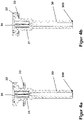
- Schnittdarstellung eines Seilführungselements mit einem separaten Dämpfungselement in Montageposition;
- Figur 4b
- wie
Figur 3a , jedoch mit einem Dichtungselement in Funktionsposition, das auch am Kopf des Seilführungselements angespritzt sein könnte; - Figur 5a
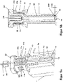
- perspektivische Darstellung einer Erfindungsvariante mit im Federgehäuse integrierten stegartigen Dämpfungselement;
- Figur 5b
- Schnittdarstellung durch die Vorrichtung gemäß
Figur 5a . -
Figur 1 zeigt den prinzipiellen Aufbau eines typischen Seilausgangsgehäuses 1, das Bestandteil eines hier nicht näher dargestellten Fensterheberantriebs ist, wobei das Gehäuse 1 geeignet ist, über seine Befestigungsdome 18 mit einem Träger sowie dem motorischen Antrieb auf der Trockenraumseite des Trägers verbunden zu werden. Der durch den motorischen Antrieb zu betätigende Seilzug ist mit der Seiltrommel 2 kraftübertragend zu verbinden. Über einen Lagerzapfen 17 wird die Seiltrommel 2 im Seiltrommelgehäuse 16 gelagert. Die beidseitig von der Seiltrommel 2 abgehenden Seilabschnitte (nicht dargestellt) verlaufen zunächst durch die Seilkanäle 15 und durchqueren dann im Kanal 30a des Führungsschaftes 30 den inneren Kanal 14 und das Federgehäuse 11 der Aufnahme 1a des Seilausgangsgehäuses 1. - Das Seilführungselement 3 weist einen inneren Führungsschaft 30 auf, über den das Seilführungselement 3 im Kanal 14 der Aufnahme 1a verschiebbar geführt ist. An den inneren Führungsschaft 30 schließt sich ein äußerer Schaft 31 an, auf dem eine schraubenförmig gewickelte Druckfeder 35 lagert. Das äußere freie Ende des Seilführungselements 3 bildet einen Kopf 32, an dessen zur Aufnahme 1a weisenden Fläche ein elastisches Dämpfungselement 33 angeordnet ist.
- Im zusammengebauten Zustand (siehe
Figur 2 ) stützt sich die Feder 35 einerseits innerhalb des Federgehäuses 11 an der Stützfläche 13 und andererseits am Kopf 32 bzw. dem vorgelagerten Dämpfungselement 33 ab. Der Seilkanal 30a des inneren Führungsschaftes 30 erweitert sich im Bereich des daran anschließenden äußeren Führungsschaftes 31 zu einer Bowdenrohr-Aufnahme 34, so dass die Spannkraft der Feder 35 einen axialen Druck auf das Bowdenrohr 40 ausüben kann, um das darin geführte Seil straff zu halten. - Der Schnitt von
Figur 3a zeigt das Seilführungselement 3, dessen Dämpfungselement 33 den freien Rand 12 des Federgehäuses 11zwar bereits berührt, jedoch ohne dieses zu komprimieren. Zwischen dem freien Ende 300 des inneren Führungsschaftes 30 und dem Anschlag 10 der Aufnahme 1a des Gehäuses 1 ist deutlich ein Spalt 100 erkennbar. Erst bei einer weiteren Erhöhung der Seilkraft treten diese Anschläge 10, 300 miteinander in Eingriff (sieheFigur 3b ), wobei das Dämpfungselement 33 auf den für diese Dimensionierung maximal möglichen Wert der Komprimierung zusammengepresst wird. Somit wird sichergestellt, dass das Dämpfungselement 33 nicht überlastet werden kann und seine dämpfenden Eigenschaften dauerhaft behält. - Mit den Darstellungen der
Figuren 4a und 4b soll angedeutet werden, dass das Dämpfungselement 33 auf unterschiedlicher Weise in die erfindungsgemäße Vorrichtung eingebracht bzw. integriert werden kann. So ist nicht nur die Bereitstellung eines separaten Dämpfungselements 33 möglich, sondern auch ein Anspritzen des Dichtungselements 33 im Wege eines sogenannten 2-Komponenten-Spritzgießprozesses, bei dem zuerst die eine Komponente, z. B. der Grundkörper des Dämpfungselements 33, und anschließende die andere Komponente, z. B. die des Dichtungselements 33, erzeugt werden, wobei ein nicht lösbarer Verbund entsteht. Natürlich ist es auch möglich, das Dämpfungselement 33 an den freien Rand 12 des Federgehäuses 11 anzuspritzen. - Die
Figuren 5a und 5b zeigen eine Variante der Erfindung, die ohne ein separates Element und auch ohne ein weiteres Material für das Dämpfungselement auskommt. Zum Zwecke der Erzeugung der gewünschten Dämpfungswirkung ist ein elastisches Federelement 33a in das Federgehäuse 11 integriert. Hierfür ist im Federgehäuse 11 eine fensterartige Aussparung 11a vorgesehen, so dass sich zwischen seitlichen, axial gerichteten Stützen 11b am freien Ende des Federgehäuses 11 ein hierzu quer verlaufender federelastischer Steg erstreckt, der das Dämpfungselement 33a bildet. Ein an der Unterseite des Kopfes 32 des Seilführungselements 3 angeformter Vorsprung 32a stellt sicher, dass die Seilkraft definiert in den mittleren Bereich des integrierten Dämpfungselements 33a eingeleitet wird. - Die Dimensionierung wurde derart vorgenommen, dass die Durchbiegung des federnden Steges 33a dem axialen Maß des Vorsprungs 32a des Kopfes 32 entspricht und dabei keine Überlastung des Dämpfungselements 33a auftreten kann. Sobald die maximale elastische Deformation des Dämpfungselements 33a erreicht wird, treten die Anschlagflächen oberhalb der seitlichen Stützen 11b mit den zugeordneten Flächen des Kopfes 32 seitlich der Vorsprünge 32a in Eingriff und verhindern so eine Überlastung des integrierten Dämpfungselements 33a.
- In dem vorliegenden Ausführungsbeispiel ist zusätzlich (aber nicht unbedingt erforderlich) ein weiteres Paar von Anschlägen 10, 300 vorgesehen, analog zur bereits beschriebenen Variante gemäß den
Figuren 3a und 3b . Demnach wird das Seilführungselement 3 bei Erhöhung der Seilkraft weiter in die Aufnahme 1a hinein geschoben, und zwar bis der Spalt 100 zwischen den Anschlägen 10, 300 überwunden ist. Diese Anschläge sollten dann zur Anwendung kommen, wenn die seitlichen Stützen 11b des Federgehäuses 11 nicht geeignet sind, die maximal mögliche Stützkraft tragen zu können. -
- 1
- Gehäuse, Seilausgangsgehäuse
- 1a
- Aufnahme für das Seilführungselement 3
- 10
- innerer Anschlag
- 11
- Federgehäuse
- 11a
- Aussparung
- 11b
- seitliche Stütze
- 12
- äußerer Anschlag; freier Rand des Federgehäuses 11
- 13
- Stützfläche für Feder 35
- 14
- innerer Kanal
- 15
- Seilkanal
- 16
- Seiltrommelgehäuse
- 17
- Lagerzapfen
- 18
- Befestigungsdom
- 100
- Spalt
- 2
- Seiltrommel
- 3
- Seilführungselement
- 30
- innerer Führungsschaft
- 30a
- Seilkanal des Führungsschaftes
- 31
- äußerer Führungsschaft
- 32
- Kopf
- 32a
- Vorsprung
- 33
- federelastische Dämpfungselement, separat ausgebildet
- 33a
- federelastisches Dämpfungselement, integriert
- 34
- Bowdenrohr-Aufnahme
- 300
- freies Ende
- 4
- Seil
- 40
- Bowdenrohr
Claims (10)
- Vorrichtung zur Kompensation einer Seillose innerhalb eines Seilzug-Fensterhebers, dessen Seilzug wenigstens einen Abschnitt mit einem Bowden aufweist,o wobei ein das Bowdenende aufnehmendes Seilführungselement (3) in einer Aufnahme (1a) eines Seilantriebsgehäuses (1) der Vorrichtung axial verschiebbar lagert,∘ wobei zwischen einer Stützfläche (13) der Aufnahme und einem Kopf (32) des Seilführungselements eine Feder (35) angeordnet ist, die den Seilzug unter Spannung hält und dadurch geeignet ist, Seillose zu kompensieren, undo wobei am Seilführungselement und an dessen Aufnahme Anschlagflächen (12, 32) vorgesehen sind, die bei Belastung des Seilzugs miteinander in Eingriff treten können und dadurch eine weitere Kompensation der Feder unterbinden, wobei zwischen den Anschlägen ein elastisches, Anschlagsgeräusche dämpfendes Material (33) angeordnet ist
dadurch gekennzeichnet,
dass, zwischen dem Seilführungselement (3) und dessen Aufnahme (1a) an dem Seilantriebsgehäuse (1), zwei Anschlagpaare derart ausgebildet sind,o dass bei einer die Spannkraft der Feder übersteigenden Seilkraft zunächst die Anschläge eines ersten Anschlagpaars (12, 32) mit einem zwischengeordneten Dämpfungselements (33, 33a) miteinander in Eingriff treten, undo dass nach einem vorgegebenen Weg der Kompression des Dämpfungselements (33, 33a) die Anschläge eines zweiten, nicht oder härter gedämpften Anschlagpaars (10, 300) miteinander in Eingriff treten. - Vorrichtung nach Anspruch 1, dadurch gekennzeichnet, dass die Anschläge (12, 32) des ersten Anschlagpaars durch einen äußeren Rand (12) eines an dem Seilantriebsgehäuse (1) vorgesehenen Federgehäuses (11) und durch die dem äußeren Rand (12) zugewandte Fläche des Kopfes (32) des Seilführungselements (3) gebildet sind.
- Vorrichtung nach den Ansprüchen 1 und 2, dadurch gekennzeichnet, dass das zwischen den Anschlägen (12, 32) angeordnete Dämpfungselement (33) des ersten Anschlagpaars (12, 32) als separates Element aus einem Elastomer oder aus Gummi ausgebildet ist.
- Vorrichtung nach den Ansprüchen 1 und 2, dadurch gekennzeichnet, dass das zwischen den Anschlägen (12, 32) angeordnete Dämpfungselement (33) des ersten Anschlagpaars (12, 32) in 2-Komponenten-Spritzgießtechnik am Kopf (32) des Seilführungselements (3) oder am freien Rand (12) eines an dem Seilantriebsgehäuse (1) vorgesehenen Federgehäuses (11) der Aufnahme (1a) angespritzt ist.
- Vorrichtung nach den Ansprüchen 1 und 2, dadurch gekennzeichnet, dass das zwischen den Anschlägen (12, 32) angeordnete Dämpfungselement (33a) des ersten Anschlagpaars (12, 32) als integrierter Bestandteil eines an dem Seilantriebsgehäuse (1) vorgesehenen Federgehäuses (11) ausgebildet ist.
- Vorrichtung nach Anspruch 5, dadurch gekennzeichnet, dass das Federgehäuse (11) eine Aussparung (11a) aufweist, so dass sich ein federnder Abschnitt (33a) zwischen den seitlichen Stützen (11b) erstreckt und als Dämpfungselement (33a) wirken kann, wobei ein am Kopf (32) angeformter Vorsprung (32a) auf das Dämpfungselement (33a) einwirken kann, bis die an den Vorsprung (32a) seitlich angrenzenden Bereiche des Kopfes (32) auf den Anschlagflächen der nicht elastischen seitlichen Stützen (11b) aufliegen.
- Vorrichtung nach Anspruch 1, dadurch gekennzeichnet, dass die Anschläge (10, 300) des zweiten Anschlagpaars durch einen im inneren Kanal (14) der Aufnahme (1a) vorspringenden inneren Anschlag (10) und das freie Ende (300) des inneren Führungsschaftes (30) des Seilführungselements (3) gebildet sind.
- Vorrichtung nach einem der voranstehenden Ansprüche, dadurch gekennzeichnet, dass der innere Anschlag (10) oder das freie Ende (300) des inneren Führungsschaftes (30) mit einem Dämpfungselement ausgestattet ist, das eine wesentlich geringere Elastizität und eine wesentlich höhere Dauerbelastbarkeit als das andere Dämpfungselement (33, 33a) aufweist.
- Vorrichtung nach einem der voranstehenden Ansprüche, dadurch gekennzeichnet, dass das Seilausgangsgehäus (1) Teil eines Fensterheberantriebs der Vorrichtung oder eines Trägerelements, insbesondere einer Trägerplatte eines Türmoduls der Vorrichtung ist.
- Vorrichtung nach einem der voranstehenden Ansprüche, gekennzeichnet durch eine kinematische Umkehr derart, dass der elastischere Anschlag im Bereich des zweiten Anschlagpaares (10, 300) und der weniger elastische bzw. härtere Anschlag im Bereich des ersten Anschlagpaares (12, 32) angeordnet sind.
Applications Claiming Priority (2)
| Application Number | Priority Date | Filing Date | Title |
|---|---|---|---|
| DE202016005232.3U DE202016005232U1 (de) | 2016-08-17 | 2016-08-17 | Vorrichtung zur Kompensation einer Seillose innerhalb eines Seilzug-Fensterhebers, dessen Seilzug wenigstens einen Abschnitt mit einem Bowden aufweist |
| PCT/EP2017/070270 WO2018033457A1 (de) | 2016-08-17 | 2017-08-10 | Vorrichtung zur spannung eines bowdenzugs eines seilzug-fensterhebers |
Publications (2)
| Publication Number | Publication Date |
|---|---|
| EP3500715A1 EP3500715A1 (de) | 2019-06-26 |
| EP3500715B1 true EP3500715B1 (de) | 2022-12-28 |
Family
ID=59745876
Family Applications (1)
| Application Number | Title | Priority Date | Filing Date |
|---|---|---|---|
| EP17761022.7A Active EP3500715B1 (de) | 2016-08-17 | 2017-08-10 | Vorrichtung zur spannung eines bowdenzugs eines seilzug-fensterhebers |
Country Status (5)
| Country | Link |
|---|---|
| US (1) | US11326382B2 (de) |
| EP (1) | EP3500715B1 (de) |
| CN (1) | CN109642447B (de) |
| DE (1) | DE202016005232U1 (de) |
| WO (1) | WO2018033457A1 (de) |
Families Citing this family (6)
| Publication number | Priority date | Publication date | Assignee | Title |
|---|---|---|---|---|
| DE102020200907A1 (de) | 2020-01-27 | 2021-07-29 | Brose Fahrzeugteile Se & Co. Kommanditgesellschaft, Bamberg | Spannvorrichtung und Seilfensterheber mit einer solchen Spannvorrichtung |
| DE102020201696A1 (de) | 2020-02-11 | 2021-08-12 | Brose Fahrzeugteile Se & Co. Kommanditgesellschaft, Bamberg | Seilantriebsvorrichtung eines Kraftfahrzeugs |
| DE102020212792B4 (de) | 2020-10-09 | 2025-08-14 | Brose Fahrzeugteile Se & Co. Kommanditgesellschaft, Bamberg | Fensterheberbaugruppe sowie Verfahren zur Montage eines Seilantriebsgehäuses |
| DE102020213193A1 (de) | 2020-10-20 | 2022-04-21 | Brose Fahrzeugteile Se & Co. Kommanditgesellschaft, Bamberg | Seilantriebsvorrichtung eines Kraftfahrzeugs |
| DE102024117747A1 (de) * | 2023-06-23 | 2024-12-24 | Inteva Products, Llc | Spannvorrichtung für einen Fensterheber |
| JP7808158B1 (ja) * | 2024-09-11 | 2026-01-28 | 信昌機械廠股▲ふん▼有限公司 | 張力調整装置及び張力調整装置を備える窓昇降装置 |
Family Cites Families (23)
| Publication number | Priority date | Publication date | Assignee | Title |
|---|---|---|---|---|
| DE2849445A1 (de) * | 1978-11-15 | 1980-05-29 | Volkswagenwerk Ag | Fensterheber |
| US4378713A (en) * | 1980-06-10 | 1983-04-05 | Acco Industries Inc. | Self-adjusting cable control device |
| FR2496197A1 (fr) * | 1980-12-11 | 1982-06-18 | Dba | Commande mecanique par cable coulissant axialement dans une gaine flexible |
| DE3432178C1 (de) * | 1984-08-31 | 1986-01-02 | Brose Fahrzeugteile GmbH & Co KG, 8630 Coburg | Bowdenzug-Fensterheber,insbesondere fuer Kraftfahrzeuge |
| FR2584469A1 (fr) | 1985-07-05 | 1987-01-09 | Mecanisme Cie Indle | Dispositif tendeur de cable unidirectionnel pour leve-vitre de vehicule automobile |
| DE3737733C1 (en) * | 1987-11-06 | 1988-05-19 | Audi Ag | Window lift for a motor vehicle |
| DE19700746C1 (de) * | 1997-01-11 | 1998-08-13 | Brose Fahrzeugteile | Vorrichtung zum automatischen, stufenweisen Seillängenausgleich eines Bowdenzugsystems |
| DE19706866C2 (de) * | 1997-02-21 | 1999-04-29 | Brose Fahrzeugteile | Vorrichtung zum automatischen, stufenweisen Seillängenausgleich eines Bowdenzugsystems |
| DE19852977C1 (de) * | 1998-11-17 | 1999-10-07 | Brose Fahrzeugteile | Vorrichtung zur Gewährleistung einer Relativbewegung zwischen Teilen eines Seilfensterhebers |
| US6193621B1 (en) * | 1999-05-06 | 2001-02-27 | Fanuc Robotics North America, Inc. | Take-up device for tensioning motion transmitting control cables |
| FR2821879B1 (fr) * | 2001-03-07 | 2003-12-05 | Meritor Light Vehicle Sys Ltd | Dispositif anti-pincement de leve-vitre a cable |
| FR2857716B1 (fr) * | 2003-07-18 | 2005-09-09 | Arvinmeritor Light Vehicle Sys | Tendeur de cable de leve-vitre |
| JP2005083171A (ja) * | 2003-09-11 | 2005-03-31 | Mitsuba Corp | 車両用開閉装置 |
| WO2006012746A1 (en) * | 2004-08-06 | 2006-02-09 | Magna Closures Inc. | Dual-guided single rail window regulator |
| JP4579864B2 (ja) * | 2006-05-30 | 2010-11-10 | シロキ工業株式会社 | ウインドレギュレータ |
| DE202007007032U1 (de) | 2006-11-28 | 2008-04-10 | Brose Fahrzeugteile Gmbh & Co. Kommanditgesellschaft, Coburg | Befestigungsanordnung zur Befestigung einer Antriebseinheit eines Seil-Fensterhebers für Kraftfahrzeuge an einem plattenförmigen Träger sowie Kraftfahrzeugtür mit selbiger |
| US20100043295A1 (en) * | 2008-08-20 | 2010-02-25 | Geoffrey Barr | Automatic cable tensioner for cable drive window regulators |
| DE202008011934U1 (de) | 2008-09-05 | 2010-02-11 | Brose Fahrzeugteile Gmbh & Co. Kommanditgesellschaft, Hallstadt | Fensterhebervorrichtung mit einem Führungselement für ein auf- und abwickelbares Zugmittel |
| WO2012083427A1 (en) * | 2010-12-22 | 2012-06-28 | Magna Closures Inc. | Tensioning assembly for cable drive |
| CN203129828U (zh) * | 2012-12-27 | 2013-08-14 | 上海汽车集团股份有限公司 | 车窗玻璃升降装置 |
| FR3003510B1 (fr) * | 2013-03-21 | 2015-03-27 | Inteva Products France Sas | Arret de gaine pivotant pour gaine, support, rail de guidage, ensemble, leve-vitre, procede de montage correspondants |
| US9637969B2 (en) * | 2014-08-07 | 2017-05-02 | Hi-Lex Controls, Inc. | Integrated window regulator assembly |
| US10151339B2 (en) * | 2017-05-15 | 2018-12-11 | Hsin Chong Machinery Works Co. Ltd. | Cable length automatic adjustment device for vehicle window lifter |
-
2016
- 2016-08-17 DE DE202016005232.3U patent/DE202016005232U1/de not_active Expired - Lifetime
-
2017
- 2017-08-10 CN CN201780050814.8A patent/CN109642447B/zh not_active Expired - Fee Related
- 2017-08-10 US US16/326,019 patent/US11326382B2/en active Active
- 2017-08-10 WO PCT/EP2017/070270 patent/WO2018033457A1/de not_active Ceased
- 2017-08-10 EP EP17761022.7A patent/EP3500715B1/de active Active
Also Published As
| Publication number | Publication date |
|---|---|
| CN109642447B (zh) | 2020-06-19 |
| WO2018033457A1 (de) | 2018-02-22 |
| DE202016005232U1 (de) | 2017-11-20 |
| US20210324669A1 (en) | 2021-10-21 |
| CN109642447A (zh) | 2019-04-16 |
| EP3500715A1 (de) | 2019-06-26 |
| US11326382B2 (en) | 2022-05-10 |
Similar Documents
| Publication | Publication Date | Title |
|---|---|---|
| WO2018033457A1 (de) | Vorrichtung zur spannung eines bowdenzugs eines seilzug-fensterhebers | |
| DE60301994T2 (de) | Kunststoffniet | |
| DE102015209600B4 (de) | Kugelgewindetrieb | |
| EP2425079B1 (de) | Dämpfer für möbel | |
| DE102013011469A1 (de) | Führungseinrichtung für eine Schwimmsattel-Scheibenbremse | |
| DE10300876A1 (de) | Gleitstück für Türschliesser oder Drehflügelantriebe | |
| DE102019124722A1 (de) | Türfeststellermechanismus | |
| EP2840214A1 (de) | Türschließanordnung | |
| EP1498569B1 (de) | Türdichtung | |
| DE2941274A1 (de) | Elastische halterung | |
| DE2406906A1 (de) | Tuerfeststeller, insbesondere fuer kraftfahrzeuge | |
| DE102009007416A1 (de) | Dämpfungseinrichtung für Möbeltüren | |
| EP2072730B1 (de) | Beschlag für Hebe-Schiebeelemente und Hebe-Schiebeelement | |
| DE10153263B4 (de) | Türschieber oder Drehflügelantrieb | |
| EP2818619B1 (de) | Vorrichtung zur Regelung der Schließfolge einer zweiflügeligen Drehtüranlage | |
| DE102017128077A1 (de) | Modulierbares Sicherheitsventil | |
| DE102010041606B4 (de) | Dämpfventilanordnung für einen Schwingungsdämpfer | |
| DE102005036636B4 (de) | Endanschlag für bewegte Teile sowie Fahrzeug mit derartigem Endanschlag | |
| DE102008013494A1 (de) | Türschließer | |
| DE10035378B4 (de) | Dichtungsanordnung für eine schwellenlose Türe | |
| DE19934383A1 (de) | Dämpfungseinrichtung und Ventileinsatz für eine solche Dämpfungseinrichtung | |
| DE102018202811B4 (de) | Antriebsvorrichtung für Türflügel und damit ausgestattete Türanordnung | |
| DE3007653A1 (de) | Seilfensterheber | |
| EP2818618A1 (de) | Vorrichtung zur Regelung der Schließfolge einer zweiflügeligen Drehtüranlage | |
| DE112019002016T5 (de) | Sicherheitsvorrichtung für eine Schiebetür |
Legal Events
| Date | Code | Title | Description |
|---|---|---|---|
| STAA | Information on the status of an ep patent application or granted ep patent |
Free format text: STATUS: UNKNOWN |
|
| STAA | Information on the status of an ep patent application or granted ep patent |
Free format text: STATUS: THE INTERNATIONAL PUBLICATION HAS BEEN MADE |
|
| PUAI | Public reference made under article 153(3) epc to a published international application that has entered the european phase |
Free format text: ORIGINAL CODE: 0009012 |
|
| STAA | Information on the status of an ep patent application or granted ep patent |
Free format text: STATUS: REQUEST FOR EXAMINATION WAS MADE |
|
| 17P | Request for examination filed |
Effective date: 20190318 |
|
| AK | Designated contracting states |
Kind code of ref document: A1 Designated state(s): AL AT BE BG CH CY CZ DE DK EE ES FI FR GB GR HR HU IE IS IT LI LT LU LV MC MK MT NL NO PL PT RO RS SE SI SK SM TR |
|
| AX | Request for extension of the european patent |
Extension state: BA ME |
|
| DAV | Request for validation of the european patent (deleted) | ||
| DAX | Request for extension of the european patent (deleted) | ||
| STAA | Information on the status of an ep patent application or granted ep patent |
Free format text: STATUS: EXAMINATION IS IN PROGRESS |
|
| RAP1 | Party data changed (applicant data changed or rights of an application transferred) |
Owner name: BROSE FAHRZEUGTEILE SE & CO. KOMMANDITGESELLSCHAFT, BAMBERG |
|
| 17Q | First examination report despatched |
Effective date: 20200406 |
|
| GRAP | Despatch of communication of intention to grant a patent |
Free format text: ORIGINAL CODE: EPIDOSNIGR1 |
|
| STAA | Information on the status of an ep patent application or granted ep patent |
Free format text: STATUS: GRANT OF PATENT IS INTENDED |
|
| INTG | Intention to grant announced |
Effective date: 20220802 |
|
| GRAS | Grant fee paid |
Free format text: ORIGINAL CODE: EPIDOSNIGR3 |
|
| GRAA | (expected) grant |
Free format text: ORIGINAL CODE: 0009210 |
|
| STAA | Information on the status of an ep patent application or granted ep patent |
Free format text: STATUS: THE PATENT HAS BEEN GRANTED |
|
| AK | Designated contracting states |
Kind code of ref document: B1 Designated state(s): AL AT BE BG CH CY CZ DE DK EE ES FI FR GB GR HR HU IE IS IT LI LT LU LV MC MK MT NL NO PL PT RO RS SE SI SK SM TR |
|
| REG | Reference to a national code |
Ref country code: GB Ref legal event code: FG4D Free format text: NOT ENGLISH |
|
| REG | Reference to a national code |
Ref country code: CH Ref legal event code: EP |
|
| REG | Reference to a national code |
Ref country code: DE Ref legal event code: R096 Ref document number: 502017014273 Country of ref document: DE |
|
| REG | Reference to a national code |
Ref country code: AT Ref legal event code: REF Ref document number: 1540580 Country of ref document: AT Kind code of ref document: T Effective date: 20230115 |
|
| REG | Reference to a national code |
Ref country code: IE Ref legal event code: FG4D Free format text: LANGUAGE OF EP DOCUMENT: GERMAN |
|
| REG | Reference to a national code |
Ref country code: LT Ref legal event code: MG9D |
|
| PG25 | Lapsed in a contracting state [announced via postgrant information from national office to epo] |
Ref country code: SE Free format text: LAPSE BECAUSE OF FAILURE TO SUBMIT A TRANSLATION OF THE DESCRIPTION OR TO PAY THE FEE WITHIN THE PRESCRIBED TIME-LIMIT Effective date: 20221228 Ref country code: NO Free format text: LAPSE BECAUSE OF FAILURE TO SUBMIT A TRANSLATION OF THE DESCRIPTION OR TO PAY THE FEE WITHIN THE PRESCRIBED TIME-LIMIT Effective date: 20230328 Ref country code: LT Free format text: LAPSE BECAUSE OF FAILURE TO SUBMIT A TRANSLATION OF THE DESCRIPTION OR TO PAY THE FEE WITHIN THE PRESCRIBED TIME-LIMIT Effective date: 20221228 Ref country code: FI Free format text: LAPSE BECAUSE OF FAILURE TO SUBMIT A TRANSLATION OF THE DESCRIPTION OR TO PAY THE FEE WITHIN THE PRESCRIBED TIME-LIMIT Effective date: 20221228 |
|
| REG | Reference to a national code |
Ref country code: NL Ref legal event code: MP Effective date: 20221228 |
|
| PG25 | Lapsed in a contracting state [announced via postgrant information from national office to epo] |
Ref country code: RS Free format text: LAPSE BECAUSE OF FAILURE TO SUBMIT A TRANSLATION OF THE DESCRIPTION OR TO PAY THE FEE WITHIN THE PRESCRIBED TIME-LIMIT Effective date: 20221228 Ref country code: LV Free format text: LAPSE BECAUSE OF FAILURE TO SUBMIT A TRANSLATION OF THE DESCRIPTION OR TO PAY THE FEE WITHIN THE PRESCRIBED TIME-LIMIT Effective date: 20221228 Ref country code: HR Free format text: LAPSE BECAUSE OF FAILURE TO SUBMIT A TRANSLATION OF THE DESCRIPTION OR TO PAY THE FEE WITHIN THE PRESCRIBED TIME-LIMIT Effective date: 20221228 Ref country code: GR Free format text: LAPSE BECAUSE OF FAILURE TO SUBMIT A TRANSLATION OF THE DESCRIPTION OR TO PAY THE FEE WITHIN THE PRESCRIBED TIME-LIMIT Effective date: 20230329 |
|
| PG25 | Lapsed in a contracting state [announced via postgrant information from national office to epo] |
Ref country code: NL Free format text: LAPSE BECAUSE OF FAILURE TO SUBMIT A TRANSLATION OF THE DESCRIPTION OR TO PAY THE FEE WITHIN THE PRESCRIBED TIME-LIMIT Effective date: 20221228 |
|
| PG25 | Lapsed in a contracting state [announced via postgrant information from national office to epo] |
Ref country code: SM Free format text: LAPSE BECAUSE OF FAILURE TO SUBMIT A TRANSLATION OF THE DESCRIPTION OR TO PAY THE FEE WITHIN THE PRESCRIBED TIME-LIMIT Effective date: 20221228 Ref country code: RO Free format text: LAPSE BECAUSE OF FAILURE TO SUBMIT A TRANSLATION OF THE DESCRIPTION OR TO PAY THE FEE WITHIN THE PRESCRIBED TIME-LIMIT Effective date: 20221228 Ref country code: PT Free format text: LAPSE BECAUSE OF FAILURE TO SUBMIT A TRANSLATION OF THE DESCRIPTION OR TO PAY THE FEE WITHIN THE PRESCRIBED TIME-LIMIT Effective date: 20230428 Ref country code: ES Free format text: LAPSE BECAUSE OF FAILURE TO SUBMIT A TRANSLATION OF THE DESCRIPTION OR TO PAY THE FEE WITHIN THE PRESCRIBED TIME-LIMIT Effective date: 20221228 Ref country code: EE Free format text: LAPSE BECAUSE OF FAILURE TO SUBMIT A TRANSLATION OF THE DESCRIPTION OR TO PAY THE FEE WITHIN THE PRESCRIBED TIME-LIMIT Effective date: 20221228 Ref country code: CZ Free format text: LAPSE BECAUSE OF FAILURE TO SUBMIT A TRANSLATION OF THE DESCRIPTION OR TO PAY THE FEE WITHIN THE PRESCRIBED TIME-LIMIT Effective date: 20221228 |
|
| PG25 | Lapsed in a contracting state [announced via postgrant information from national office to epo] |
Ref country code: SK Free format text: LAPSE BECAUSE OF FAILURE TO SUBMIT A TRANSLATION OF THE DESCRIPTION OR TO PAY THE FEE WITHIN THE PRESCRIBED TIME-LIMIT Effective date: 20221228 Ref country code: PL Free format text: LAPSE BECAUSE OF FAILURE TO SUBMIT A TRANSLATION OF THE DESCRIPTION OR TO PAY THE FEE WITHIN THE PRESCRIBED TIME-LIMIT Effective date: 20221228 Ref country code: IS Free format text: LAPSE BECAUSE OF FAILURE TO SUBMIT A TRANSLATION OF THE DESCRIPTION OR TO PAY THE FEE WITHIN THE PRESCRIBED TIME-LIMIT Effective date: 20230428 Ref country code: AL Free format text: LAPSE BECAUSE OF FAILURE TO SUBMIT A TRANSLATION OF THE DESCRIPTION OR TO PAY THE FEE WITHIN THE PRESCRIBED TIME-LIMIT Effective date: 20221228 |
|
| REG | Reference to a national code |
Ref country code: DE Ref legal event code: R097 Ref document number: 502017014273 Country of ref document: DE |
|
| PG25 | Lapsed in a contracting state [announced via postgrant information from national office to epo] |
Ref country code: DK Free format text: LAPSE BECAUSE OF FAILURE TO SUBMIT A TRANSLATION OF THE DESCRIPTION OR TO PAY THE FEE WITHIN THE PRESCRIBED TIME-LIMIT Effective date: 20221228 |
|
| PLBE | No opposition filed within time limit |
Free format text: ORIGINAL CODE: 0009261 |
|
| STAA | Information on the status of an ep patent application or granted ep patent |
Free format text: STATUS: NO OPPOSITION FILED WITHIN TIME LIMIT |
|
| 26N | No opposition filed |
Effective date: 20230929 |
|
| PG25 | Lapsed in a contracting state [announced via postgrant information from national office to epo] |
Ref country code: SI Free format text: LAPSE BECAUSE OF FAILURE TO SUBMIT A TRANSLATION OF THE DESCRIPTION OR TO PAY THE FEE WITHIN THE PRESCRIBED TIME-LIMIT Effective date: 20221228 |
|
| PG25 | Lapsed in a contracting state [announced via postgrant information from national office to epo] |
Ref country code: MC Free format text: LAPSE BECAUSE OF FAILURE TO SUBMIT A TRANSLATION OF THE DESCRIPTION OR TO PAY THE FEE WITHIN THE PRESCRIBED TIME-LIMIT Effective date: 20221228 |
|
| REG | Reference to a national code |
Ref country code: CH Ref legal event code: PL |
|
| PG25 | Lapsed in a contracting state [announced via postgrant information from national office to epo] |
Ref country code: MC Free format text: LAPSE BECAUSE OF FAILURE TO SUBMIT A TRANSLATION OF THE DESCRIPTION OR TO PAY THE FEE WITHIN THE PRESCRIBED TIME-LIMIT Effective date: 20221228 |
|
| PG25 | Lapsed in a contracting state [announced via postgrant information from national office to epo] |
Ref country code: LU Free format text: LAPSE BECAUSE OF NON-PAYMENT OF DUE FEES Effective date: 20230810 |
|
| GBPC | Gb: european patent ceased through non-payment of renewal fee |
Effective date: 20230810 |
|
| PG25 | Lapsed in a contracting state [announced via postgrant information from national office to epo] |
Ref country code: LU Free format text: LAPSE BECAUSE OF NON-PAYMENT OF DUE FEES Effective date: 20230810 Ref country code: CH Free format text: LAPSE BECAUSE OF NON-PAYMENT OF DUE FEES Effective date: 20230831 |
|
| REG | Reference to a national code |
Ref country code: BE Ref legal event code: MM Effective date: 20230831 |
|
| REG | Reference to a national code |
Ref country code: IE Ref legal event code: MM4A |
|
| PG25 | Lapsed in a contracting state [announced via postgrant information from national office to epo] |
Ref country code: IT Free format text: LAPSE BECAUSE OF FAILURE TO SUBMIT A TRANSLATION OF THE DESCRIPTION OR TO PAY THE FEE WITHIN THE PRESCRIBED TIME-LIMIT Effective date: 20221228 |
|
| PG25 | Lapsed in a contracting state [announced via postgrant information from national office to epo] |
Ref country code: IE Free format text: LAPSE BECAUSE OF NON-PAYMENT OF DUE FEES Effective date: 20230810 |
|
| PG25 | Lapsed in a contracting state [announced via postgrant information from national office to epo] |
Ref country code: GB Free format text: LAPSE BECAUSE OF NON-PAYMENT OF DUE FEES Effective date: 20230810 |
|
| PG25 | Lapsed in a contracting state [announced via postgrant information from national office to epo] |
Ref country code: IE Free format text: LAPSE BECAUSE OF NON-PAYMENT OF DUE FEES Effective date: 20230810 Ref country code: GB Free format text: LAPSE BECAUSE OF NON-PAYMENT OF DUE FEES Effective date: 20230810 Ref country code: FR Free format text: LAPSE BECAUSE OF NON-PAYMENT OF DUE FEES Effective date: 20230831 |
|
| PG25 | Lapsed in a contracting state [announced via postgrant information from national office to epo] |
Ref country code: BE Free format text: LAPSE BECAUSE OF NON-PAYMENT OF DUE FEES Effective date: 20230831 |
|
| PGFP | Annual fee paid to national office [announced via postgrant information from national office to epo] |
Ref country code: DE Payment date: 20240831 Year of fee payment: 8 |
|
| REG | Reference to a national code |
Ref country code: AT Ref legal event code: MM01 Ref document number: 1540580 Country of ref document: AT Kind code of ref document: T Effective date: 20230810 |
|
| PG25 | Lapsed in a contracting state [announced via postgrant information from national office to epo] |
Ref country code: AT Free format text: LAPSE BECAUSE OF NON-PAYMENT OF DUE FEES Effective date: 20230810 |
|
| PG25 | Lapsed in a contracting state [announced via postgrant information from national office to epo] |
Ref country code: AT Free format text: LAPSE BECAUSE OF NON-PAYMENT OF DUE FEES Effective date: 20230810 |
|
| PG25 | Lapsed in a contracting state [announced via postgrant information from national office to epo] |
Ref country code: BG Free format text: LAPSE BECAUSE OF FAILURE TO SUBMIT A TRANSLATION OF THE DESCRIPTION OR TO PAY THE FEE WITHIN THE PRESCRIBED TIME-LIMIT Effective date: 20221228 |
|
| PG25 | Lapsed in a contracting state [announced via postgrant information from national office to epo] |
Ref country code: BG Free format text: LAPSE BECAUSE OF FAILURE TO SUBMIT A TRANSLATION OF THE DESCRIPTION OR TO PAY THE FEE WITHIN THE PRESCRIBED TIME-LIMIT Effective date: 20221228 |
|
| PG25 | Lapsed in a contracting state [announced via postgrant information from national office to epo] |
Ref country code: CY Free format text: LAPSE BECAUSE OF FAILURE TO SUBMIT A TRANSLATION OF THE DESCRIPTION OR TO PAY THE FEE WITHIN THE PRESCRIBED TIME-LIMIT; INVALID AB INITIO Effective date: 20170810 |
|
| PG25 | Lapsed in a contracting state [announced via postgrant information from national office to epo] |
Ref country code: HU Free format text: LAPSE BECAUSE OF FAILURE TO SUBMIT A TRANSLATION OF THE DESCRIPTION OR TO PAY THE FEE WITHIN THE PRESCRIBED TIME-LIMIT; INVALID AB INITIO Effective date: 20170810 |
|
| PG25 | Lapsed in a contracting state [announced via postgrant information from national office to epo] |
Ref country code: TR Free format text: LAPSE BECAUSE OF FAILURE TO SUBMIT A TRANSLATION OF THE DESCRIPTION OR TO PAY THE FEE WITHIN THE PRESCRIBED TIME-LIMIT Effective date: 20221228 |
|
| REG | Reference to a national code |
Ref country code: DE Ref legal event code: R119 Ref document number: 502017014273 Country of ref document: DE |