EP3500427B1 - Sound-absorbing panels comprising a core consisting of connected cells, wherein some of the cell walls have openings - Google Patents
Sound-absorbing panels comprising a core consisting of connected cells, wherein some of the cell walls have openings Download PDFInfo
- Publication number
- EP3500427B1 EP3500427B1 EP17757974.5A EP17757974A EP3500427B1 EP 3500427 B1 EP3500427 B1 EP 3500427B1 EP 17757974 A EP17757974 A EP 17757974A EP 3500427 B1 EP3500427 B1 EP 3500427B1
- Authority
- EP
- European Patent Office
- Prior art keywords
- panel
- layer
- core
- cells
- series
- Prior art date
- Legal status (The legal status is an assumption and is not a legal conclusion. Google has not performed a legal analysis and makes no representation as to the accuracy of the status listed.)
- Not-in-force
Links
Images


Classifications
-
- G—PHYSICS
- G10—MUSICAL INSTRUMENTS; ACOUSTICS
- G10K—SOUND-PRODUCING DEVICES; METHODS OR DEVICES FOR PROTECTING AGAINST, OR FOR DAMPING, NOISE OR OTHER ACOUSTIC WAVES IN GENERAL; ACOUSTICS NOT OTHERWISE PROVIDED FOR
- G10K11/00—Methods or devices for transmitting, conducting or directing sound in general; Methods or devices for protecting against, or for damping, noise or other acoustic waves in general
- G10K11/16—Methods or devices for protecting against, or for damping, noise or other acoustic waves in general
- G10K11/162—Selection of materials
- G10K11/168—Plural layers of different materials, e.g. sandwiches
-
- B—PERFORMING OPERATIONS; TRANSPORTING
- B32—LAYERED PRODUCTS
- B32B—LAYERED PRODUCTS, i.e. PRODUCTS BUILT-UP OF STRATA OF FLAT OR NON-FLAT, e.g. CELLULAR OR HONEYCOMB, FORM
- B32B3/00—Layered products comprising a layer with external or internal discontinuities or unevennesses, or a layer of non-planar shape; Layered products comprising a layer having particular features of form
- B32B3/10—Layered products comprising a layer with external or internal discontinuities or unevennesses, or a layer of non-planar shape; Layered products comprising a layer having particular features of form characterised by a discontinuous layer, i.e. formed of separate pieces of material
- B32B3/12—Layered products comprising a layer with external or internal discontinuities or unevennesses, or a layer of non-planar shape; Layered products comprising a layer having particular features of form characterised by a discontinuous layer, i.e. formed of separate pieces of material characterised by a layer of regularly- arranged cells, e.g. a honeycomb structure
-
- B—PERFORMING OPERATIONS; TRANSPORTING
- B32—LAYERED PRODUCTS
- B32B—LAYERED PRODUCTS, i.e. PRODUCTS BUILT-UP OF STRATA OF FLAT OR NON-FLAT, e.g. CELLULAR OR HONEYCOMB, FORM
- B32B3/00—Layered products comprising a layer with external or internal discontinuities or unevennesses, or a layer of non-planar shape; Layered products comprising a layer having particular features of form
- B32B3/26—Layered products comprising a layer with external or internal discontinuities or unevennesses, or a layer of non-planar shape; Layered products comprising a layer having particular features of form characterised by a particular shape of the outline of the cross-section of a continuous layer; characterised by a layer with cavities or internal voids ; characterised by an apertured layer
- B32B3/266—Layered products comprising a layer with external or internal discontinuities or unevennesses, or a layer of non-planar shape; Layered products comprising a layer having particular features of form characterised by a particular shape of the outline of the cross-section of a continuous layer; characterised by a layer with cavities or internal voids ; characterised by an apertured layer characterised by an apertured layer, the apertures going through the whole thickness of the layer, e.g. expanded metal, perforated layer, slit layer regular cells B32B3/12
-
- B—PERFORMING OPERATIONS; TRANSPORTING
- B60—VEHICLES IN GENERAL
- B60R—VEHICLES, VEHICLE FITTINGS, OR VEHICLE PARTS, NOT OTHERWISE PROVIDED FOR
- B60R13/00—Elements for body-finishing, identifying, or decorating; Arrangements or adaptations for advertising purposes
- B60R13/08—Insulating elements, e.g. for sound insulation
-
- E—FIXED CONSTRUCTIONS
- E04—BUILDING
- E04B—GENERAL BUILDING CONSTRUCTIONS; WALLS, e.g. PARTITIONS; ROOFS; FLOORS; CEILINGS; INSULATION OR OTHER PROTECTION OF BUILDINGS
- E04B1/00—Constructions in general; Structures which are not restricted either to walls, e.g. partitions, or floors or ceilings or roofs
- E04B1/62—Insulation or other protection; Elements or use of specified material therefor
- E04B1/74—Heat, sound or noise insulation, absorption, or reflection; Other building methods affording favourable thermal or acoustical conditions, e.g. accumulating of heat within walls
- E04B1/82—Heat, sound or noise insulation, absorption, or reflection; Other building methods affording favourable thermal or acoustical conditions, e.g. accumulating of heat within walls specifically with respect to sound only
- E04B1/84—Sound-absorbing elements
- E04B1/86—Sound-absorbing elements slab-shaped
-
- G—PHYSICS
- G10—MUSICAL INSTRUMENTS; ACOUSTICS
- G10K—SOUND-PRODUCING DEVICES; METHODS OR DEVICES FOR PROTECTING AGAINST, OR FOR DAMPING, NOISE OR OTHER ACOUSTIC WAVES IN GENERAL; ACOUSTICS NOT OTHERWISE PROVIDED FOR
- G10K11/00—Methods or devices for transmitting, conducting or directing sound in general; Methods or devices for protecting against, or for damping, noise or other acoustic waves in general
- G10K11/16—Methods or devices for protecting against, or for damping, noise or other acoustic waves in general
- G10K11/172—Methods or devices for protecting against, or for damping, noise or other acoustic waves in general using resonance effects
-
- B—PERFORMING OPERATIONS; TRANSPORTING
- B32—LAYERED PRODUCTS
- B32B—LAYERED PRODUCTS, i.e. PRODUCTS BUILT-UP OF STRATA OF FLAT OR NON-FLAT, e.g. CELLULAR OR HONEYCOMB, FORM
- B32B2250/00—Layers arrangement
- B32B2250/03—3 layers
-
- B—PERFORMING OPERATIONS; TRANSPORTING
- B32—LAYERED PRODUCTS
- B32B—LAYERED PRODUCTS, i.e. PRODUCTS BUILT-UP OF STRATA OF FLAT OR NON-FLAT, e.g. CELLULAR OR HONEYCOMB, FORM
- B32B2250/00—Layers arrangement
- B32B2250/04—4 layers
-
- B—PERFORMING OPERATIONS; TRANSPORTING
- B32—LAYERED PRODUCTS
- B32B—LAYERED PRODUCTS, i.e. PRODUCTS BUILT-UP OF STRATA OF FLAT OR NON-FLAT, e.g. CELLULAR OR HONEYCOMB, FORM
- B32B2250/00—Layers arrangement
- B32B2250/05—5 or more layers
-
- B—PERFORMING OPERATIONS; TRANSPORTING
- B32—LAYERED PRODUCTS
- B32B—LAYERED PRODUCTS, i.e. PRODUCTS BUILT-UP OF STRATA OF FLAT OR NON-FLAT, e.g. CELLULAR OR HONEYCOMB, FORM
- B32B2307/00—Properties of the layers or laminate
- B32B2307/10—Properties of the layers or laminate having particular acoustical properties
- B32B2307/102—Insulating
-
- B—PERFORMING OPERATIONS; TRANSPORTING
- B32—LAYERED PRODUCTS
- B32B—LAYERED PRODUCTS, i.e. PRODUCTS BUILT-UP OF STRATA OF FLAT OR NON-FLAT, e.g. CELLULAR OR HONEYCOMB, FORM
- B32B2307/00—Properties of the layers or laminate
- B32B2307/50—Properties of the layers or laminate having particular mechanical properties
- B32B2307/546—Flexural strength; Flexion stiffness
-
- B—PERFORMING OPERATIONS; TRANSPORTING
- B32—LAYERED PRODUCTS
- B32B—LAYERED PRODUCTS, i.e. PRODUCTS BUILT-UP OF STRATA OF FLAT OR NON-FLAT, e.g. CELLULAR OR HONEYCOMB, FORM
- B32B2605/00—Vehicles
- B32B2605/003—Interior finishings
-
- B—PERFORMING OPERATIONS; TRANSPORTING
- B32—LAYERED PRODUCTS
- B32B—LAYERED PRODUCTS, i.e. PRODUCTS BUILT-UP OF STRATA OF FLAT OR NON-FLAT, e.g. CELLULAR OR HONEYCOMB, FORM
- B32B2607/00—Walls, panels
-
- B—PERFORMING OPERATIONS; TRANSPORTING
- B60—VEHICLES IN GENERAL
- B60N—SEATS SPECIALLY ADAPTED FOR VEHICLES; VEHICLE PASSENGER ACCOMMODATION NOT OTHERWISE PROVIDED FOR
- B60N3/00—Arrangements or adaptations of other passenger fittings, not otherwise provided for
- B60N3/04—Arrangements or adaptations of other passenger fittings, not otherwise provided for of floor mats or carpets
- B60N3/044—Arrangements or adaptations of other passenger fittings, not otherwise provided for of floor mats or carpets of removable mats
-
- B—PERFORMING OPERATIONS; TRANSPORTING
- B60—VEHICLES IN GENERAL
- B60R—VEHICLES, VEHICLE FITTINGS, OR VEHICLE PARTS, NOT OTHERWISE PROVIDED FOR
- B60R13/00—Elements for body-finishing, identifying, or decorating; Arrangements or adaptations for advertising purposes
- B60R13/08—Insulating elements, e.g. for sound insulation
- B60R13/0815—Acoustic or thermal insulation of passenger compartments
-
- B—PERFORMING OPERATIONS; TRANSPORTING
- B60—VEHICLES IN GENERAL
- B60R—VEHICLES, VEHICLE FITTINGS, OR VEHICLE PARTS, NOT OTHERWISE PROVIDED FOR
- B60R13/00—Elements for body-finishing, identifying, or decorating; Arrangements or adaptations for advertising purposes
- B60R13/08—Insulating elements, e.g. for sound insulation
- B60R13/0838—Insulating elements, e.g. for sound insulation for engine compartments
-
- B—PERFORMING OPERATIONS; TRANSPORTING
- B60—VEHICLES IN GENERAL
- B60R—VEHICLES, VEHICLE FITTINGS, OR VEHICLE PARTS, NOT OTHERWISE PROVIDED FOR
- B60R13/00—Elements for body-finishing, identifying, or decorating; Arrangements or adaptations for advertising purposes
- B60R13/08—Insulating elements, e.g. for sound insulation
- B60R13/0861—Insulating elements, e.g. for sound insulation for covering undersurfaces of vehicles, e.g. wheel houses
-
- E—FIXED CONSTRUCTIONS
- E04—BUILDING
- E04B—GENERAL BUILDING CONSTRUCTIONS; WALLS, e.g. PARTITIONS; ROOFS; FLOORS; CEILINGS; INSULATION OR OTHER PROTECTION OF BUILDINGS
- E04B1/00—Constructions in general; Structures which are not restricted either to walls, e.g. partitions, or floors or ceilings or roofs
- E04B1/62—Insulation or other protection; Elements or use of specified material therefor
- E04B1/74—Heat, sound or noise insulation, absorption, or reflection; Other building methods affording favourable thermal or acoustical conditions, e.g. accumulating of heat within walls
- E04B1/82—Heat, sound or noise insulation, absorption, or reflection; Other building methods affording favourable thermal or acoustical conditions, e.g. accumulating of heat within walls specifically with respect to sound only
- E04B1/84—Sound-absorbing elements
- E04B1/8409—Sound-absorbing elements sheet-shaped
-
- E—FIXED CONSTRUCTIONS
- E04—BUILDING
- E04B—GENERAL BUILDING CONSTRUCTIONS; WALLS, e.g. PARTITIONS; ROOFS; FLOORS; CEILINGS; INSULATION OR OTHER PROTECTION OF BUILDINGS
- E04B1/00—Constructions in general; Structures which are not restricted either to walls, e.g. partitions, or floors or ceilings or roofs
- E04B1/62—Insulation or other protection; Elements or use of specified material therefor
- E04B1/74—Heat, sound or noise insulation, absorption, or reflection; Other building methods affording favourable thermal or acoustical conditions, e.g. accumulating of heat within walls
- E04B1/82—Heat, sound or noise insulation, absorption, or reflection; Other building methods affording favourable thermal or acoustical conditions, e.g. accumulating of heat within walls specifically with respect to sound only
- E04B1/84—Sound-absorbing elements
- E04B2001/8423—Tray or frame type panels or blocks, with or without acoustical filling
- E04B2001/8428—Tray or frame type panels or blocks, with or without acoustical filling containing specially shaped acoustical bodies, e.g. funnels, egg-crates, fanfolds
Definitions
- Sound-absorbing panels are sometimes used to reduce noise in, for example, automobiles and other modes of transportation.
- Helmholtz resonator designs can effectively absorb low frequency sound, but the need for a cavity of sufficient volume often leads to a thickness in excess of 40 mm.
- Panels of less than 20 mm thickness, particularly less than 10 mm thickness, that can absorb frequencies below 1400 Hz, are particularly desirable for use in industrial, office and home settings. Lightweight panels that may be shaped into finished articles with curved surfaces would be especially useful in transportation. Panels made of recyclable thermoplastic materials would offer a further sustainability advantage.
- GB2486120 reports a composite acoustic panel employed in an inlet passage of a gas turbine engine or turbofan engine of the type fitted to commercial aircraft and comprises a permeable face-layer made of a composite material, an impermeable backing sheet made of a composite material and a sound absorbing layer which may be a metallic foam or metallic honeycomb structure. It is manufactured by a double polymerization process for the face-layer and the remainder of the acoustic panel and finally a perforation step, such as by drilling spindles or laser to perforate the face-layer according to a pre-determined perforation distribution.
- US2009/0166127 A1 reports an aircraft cabin panel for sound absorption, with a sandwich construction, comprising a core layer that comprises a plurality of tube-like or honeycomb-like cells that extend in an open manner across the thickness of the core layer and that are separated from each other by cell walls and that are uniform in design.
- a first cover layer faces away from the sound field, as well as a second cover layer that faces towards the sound field and that comprises a plurality of perforation holes and adjacent cells are interconnected by way of apertures in the cell walls.
- the perforation of the second cover layer comprises a distance (b) between holes, which distance exceeds the opening width (c) of the cells of the core layer, wherein the first cover layer is closed and wherein the cell walls comprise a perforation so that they are acoustically transparent in the direction parallel to the cover layers
- US2008/0044621 A1 reports an artificial honeycomb structure, wherein at least a portion of at least one of the enclosing honeycomb cell walls is substantially porous, open, or permeable, and wherein at least one of the hollow cells comprises at least one substantially nonporous enclosing wall.
- the present disclosure describes a panel comprising first and second layers each having first and second opposed major surfaces and a core disposed there between, the second layer being free of any openings (i.e., none) between the first and second major surfaces of the second layer, wherein the core has a plurality of walls extending from the second surface of the first layer to the first surface of the second layer providing a series of connected cells, wherein some of the cell walls have openings providing fluid communication between a series of at least 3 cells, wherein each cell wall has a plurality of sides, wherein each side of a cell wall has an area, and wherein the opening in a cell wall has an area that is at least 50 (in some disclosures at least 55, 60, 65, 70, 75, or even at least 80; in some disclosures, in a range from 50 to 80) percent of the area of a side of that cell wall, and wherein the first layer has a first opening extending between the first and second major surfaces of the first layer into one and only one cell in the series of connected, fluidly
- the present disclosure describes a panel comprising first and second layers each having first and second opposed major surfaces and a core disposed there between, the second layer being free of any openings between the first and second major surfaces of the second layer, wherein the core has a plurality of walls extending from the second surface of the first layer to the first surface of the second layer providing a series of connected cells, wherein some of the cell walls have openings providing fluid communication between a series of at least 3 cells, wherein at least 50 (in some disclosures, at least 55, 60, 65, 70, 75, 80, 85, 90, 95, or even at least 100) percent of the openings in a cell wall emanate from either the first or second layer, and wherein the first layer has ; an opening extending between the first and second major surfaces of the first layer into one and only one cell in the series of connected, fluidly communicating cells.
- the present disclosure describes an article comprising a panel comprising first and second layers each having first and second opposed major surfaces and a core disposed there between, the second layer being free of any openings between the first and second major surfaces of the second layer, wherein the core has a plurality of walls extending from the second surface of the first layer to the first surface of the second layer providing a series of connected cells, wherein some of the cell walls have openings providing fluid communication between a series of at least 3 cells, wherein each cell wall has a plurality of sides, wherein each side of a cell wall has an area, and wherein the opening in a cell wall has an area that is at least 50 percent of the area of a side of that cell wall, and wherein the first layer has an opening extending between the first and second major surfaces of the first layer into one and only one cell in the series of connected, fluidly communicating cells, wherein the panel is a flat panel or a shaped panel.
- the present disclosure describes a panel comprising first, second, and third layers, each of the first, second, and third layers having first and second opposed major surfaces and a core disposed there between, the second layer being free of any openings between the first and second major surfaces of the second layer, wherein the core has a plurality of walls extending from the second surface of the first layer to the first surface of the second layer providing a series of connected cells and a plurality of walls extending from the second surface of the second layer to the first surface of the third layer, wherein some of the cell walls have openings providing fluid communication between a series of at least 3 cells, wherein each cell wall has a plurality of sides, wherein each side of a cell wall has an area, and wherein the opening in a cell wall has an area that is at least 50 percent of the area of a side of that cell wall, and wherein the first layer has an opening extending between the first and second major surfaces of the first layer into one and only one cell in the series of connected, fluidly communicating cells.
- the present disclosure describes a laminated article comprising first and second panels, each of the first and second panels comprising first and second layers each having first and second opposed major surfaces and a core disposed there between, the second layer being free of any openings between the first and second major surfaces of the second layer, wherein the core has a plurality of walls extending from the second surface of the first layer to the first surface of the second layer providing a series of connected cells, wherein some of the cell walls have openings providing fluid communication between a series of at least 3 cells, wherein each cell wall has a plurality of sides, wherein each side of a cell wall has an area, and wherein the opening in a cell wall has an area that is at least 50 percent of the area of a side of that cell wall, and wherein the first layer has an opening extending between the first and second major surfaces of the first layer into one and only one cell in the series of connected, fluidly communicating cells, wherein the second surface of the second layer of the first panel is directly attached to the first surface of either the first layer or the second
- the present disclosure describes a method of absorbing at least one acoustical frequency below 1400 Hz by disposing an article adjacent to an item that emits at least one acoustical frequency below 1400 Hz (in some embodiments, less than 1300 Hz or even less than 1200 Hz), wherein the article comprises at least one panel comprising first and second layers each having first and second opposed major surfaces and a core disposed there between, the second layer being free of any openings between the first and second major surfaces of the second layer, wherein the core has a plurality of walls extending from the second surface of the first layer to the first surface of the second layer providing a series of connected cells, wherein some of the cell walls have openings providing fluid communication between a series of at least 3 cells, wherein each cell wall has a plurality of sides, wherein each side of a cell wall has an area, and wherein the opening in a cell wall has an area that is at least 50 percent of the area of a side of that cell wall, and wherein the first layer has
- the present disclosure describes a method of making an article, the method comprising: placing a panel in an injection mold; closing the injection mold; and injection molding plastic onto the panel in the injection mold to provide the article.
- the present disclosure describes a method of making an article, the method comprising: pre-heating a panel; placing the panel proximate to a thermoforming mold; and applying vacuum or pressure to shape the panel to provide the article.
- the present disclosure describes a method of making an article, the method comprising: pre-heating a panel; placing the panel between matched halves of a mold; and applying pressure to close the mold and shape the panel to provide the article.
- the present disclosure describes a method of making a laminated article comprising first and second panels, the method comprising welding the first and second panels together, wherein each of the first and second panels comprise first and second layers each having first and second opposed major surfaces and a core disposed there between, the second layer being free of any openings between the first and second major surfaces of the second layer, wherein the core has a plurality of walls extending from the second surface of the first layer to the first surface of the second layer providing a series of connected cells, wherein some of the cell walls have openings providing fluid communication between a series of at least 3 cells, wherein each cell wall has a plurality of sides, wherein each side of a cell wall has an area, and wherein the opening in a cell wall has an area that is at least 50 percent of the area of a side of that cell wall, and wherein the first layer has at least a first opening extending between the first and second major surfaces of the first layer into at least one cell in the series, wherein the second surface of the second layer of the first
- the present disclosure describes a method of making an article, the method comprising: obtaining first and second panels, wherein each panel comprises a layer having first and second opposed major surfaces and a core disposed on the layer, wherein the core has a plurality of walls extending from the second surface of the layer providing a series of connected cells, wherein some of the cell walls have openings providing fluid communication between a series of at least 3 cells, wherein each cell wall has a plurality of sides, wherein each side of a cell wall has an area, and wherein the opening in a cell wall has an area that is at least 50 percent of the area of a side of that cell wall, and wherein the layer has an opening extending between the first and second major surfaces of the layer into one and only one cell in the series of connected, fluidly communicating cells; heating the first and second panels; contacting the first and second panels such that the core of the first panel is aligned with the core of the second panel; and holding the first panel and the second panel in contact to form a bond between the core of the first panel
- the present disclosure describes a method of making a panel, the method comprising: generating a panel by an additive manufacturing method; wherein the panel comprises first and second layers each having first and second opposed major surfaces and a core disposed there between, the second layer being free of any openings between the first and second major surfaces of the second layer, wherein the core has a plurality of walls extending from the second surface of the first layer to the first surface of the second layer providing a series of connected cells, wherein some of the cell walls have openings providing fluid communication between a series of at least 3 cells, wherein each cell wall has a plurality of sides, wherein each side of a cell wall has an area, and wherein the opening in a cell wall has an area that is at least 50 percent of the area of a side of that cell wall, and wherein the first layer has an opening extending between the first and second major surfaces of the first layer into one and only one cell in the series of connected, fluidly communicating cells.
- the present disclosure describes a method of manufacturing an article, the method comprising: modeling an acoustical performance and a structural performance of a plurality of walls forming interconnected channels within the core of a panel; and producing the article comprising a plurality of the walls having the acoustical performance, the structural performance, or both, by an additive manufacturing method.
- the present disclosure describes a method of making an article, the method comprising: a. placing at least a portion of a panel in an injection molding die; and b. overmolding at least one mold structure on a surface of the panel in the injection molding die, thereby forming a material-to-material connection between the surface of the panel and the mold structure, wherein the panel comprises first and second layers each having first and second opposed major surfaces and a core disposed there between, the second layer being free of any openings between the first and second major surfaces of the second layer, wherein the core has a plurality of walls extending from the second surface of the first layer to the first surface of the second layer providing a series of connected cells, wherein some of the cell walls have openings providing fluid communication between a series of at least 3 cells, wherein each cell wall has a plurality of sides, wherein each side of a cell wall has an area, and wherein the opening in a cell wall has an area that is at least 50 percent of the area of a side of that cell wall, and where
- Exemplary embodiments of panels described herein can be formed into articles such as panels, walls, or other parts with curved surfaces.
- panels are shaped via thermoforming.
- panels are shaped via insert molding to provide the article.
- panels are shaped via compression molding to provide the article.
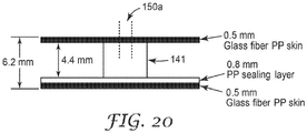
- panel 100 has first and second layers 110, 130 each having first and second opposed major surfaces, 111, 112, 131, 132 and core 120 disposed there between.
- Second layer 130 is free of any openings between first and second major surfaces 131, 132 of second layer 130.
- Core 120 has plurality of walls 141 extending from second surface 112 of first layer 110 to first surface 131 of second layer 130 providing first series 160, 160' of connected cells 140, 140'. Also shown are second and third series of cells 1160, 1160', and 2160, 2160'. Some of cell walls 141a, 141b, 141c have openings 150 providing fluid communication between first series 160 of five cells 140.
- Each cell wall 141 has a plurality of sides 171, 172. Each side 171, 172 of cell wall 141 has area A. Opening 150 in cell wall 141a has area A' that is at least 50 percent of area A.
- First layer 110 has at least first opening 190a, 190b extending between the first and second major surfaces 111, 112 of first layer 110 into at least one cell in series 160, 160'. Note that openings 190a, 190b, 190c, etc., displayed as circles, but can be any of a variety of shapes including squares, triangles, rectangles, hexagons, or other polygons. Multiple openings could also be used, including openings having at least two holes, or openings which include a woven or non-woven permeable material.
- opening 150 in a cell wall 141 emanate from either first layer 110 or second layer 130.
- opening 150 can have contours having curved and straight portions, and any straight portions can be either perpendicular to or tilted at another angle to layers 110 and 130.
- the center cell 188 could have an opening in the first layer 110.
- panel 200 has first and second layers 210, 230 each having first and second opposed major surfaces 211, 212, 231, 232 and core 220 disposed there between.
- Second layer 230 is free of any openings between first and second major surfaces 231, 232 of second layer 230.
- Core 220 has plurality of walls 241 extending from second surface 212 of first layer 210 to first surface 231 of second layer 230 providing first series 260, 260' of connected cells 240, 240'. Also shown are second and third series of cells 1260, 1260' and 2260, 2260'. Some of cell walls 241a, 241b, 241c have openings 250 providing fluid communication between first series 260 of five cells 240.
- each cell wall has a plurality of sides, wherein each side of a cell wall has an area (A), and wherein the opening in a cell wall has an area (A') that is at least 50 (in some embodiments, at least 55, 60, 65, 70, 75, or even at least 80; in some embodiments, in a range from 50 to 80) percent of the area of a side of that cell wall.
- the center cell 288 can have an opening in the first layer 210.
- the series of cells has a first cell in the series and a last cell in the series, and wherein first opening extends into either the first or last cell in the series.
- the series of cells includes a middle cell in the series.
- the series of cells has a first cell in a series, a last cell in the series, and at least one cell between the first and last cells, and wherein first opening extends into one of the cells between the first and last cells.
- one of the cells between the first and last cells is a middle cell.
- the series of cells is in a regular pattern.
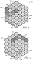
- FIG. 3 shows a group of regular repeating hexagonal arrays 360, 360', 360", 360"', 360"", 360""' of connected cells 340 and openings 390a, 390b, 390c, 390d, 390e, 390f.
- Cell 380 could be added to the 360', 360", or 360"'" series of connected cells or stand alone.
- FIG. 4 shows a group of spiral repeating hexagonal array 460, 460', 460", 460"', 460"", 460'”” of connected cells 440 and openings 490a, 490b, 490c, 490d, 490e, 490f.
- Cell 480 could be added to the 460, 460', 460", or 460""' series of connected cells or stand alone.
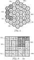
- FIG. 5 shows a group of semi-spiral repeating hexagonal array 560, 560', 560", 560"', 560"", 560”"' of connected cells 540 and openings 590a, 590b, 590c, 590d, 590e, 590f.
- Cell 580 could be added to the 560, 560', or 560"' series of connected cells or stand alone.
- FIG. 6 shows an exemplary group of rectangular arrays 660, 660', 660", 660"', 660"", 660""' of connected cells 640 and openings 690a, 690b, 690c, 690d, 690e, 690f.
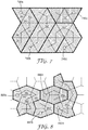
- FIG. 7 shows an exemplary group of triangular arrays 760, 760', 760", 760"' of connected cells 740 and openings 790a, 790b, 790c, 790d, 790e.
- FIG. 8 shows an exemplary group of pentagonal arrays 860, 860', 860", 860"' of connected cells 840 and openings 890a, 890b, 890c, 859d, 890e.
- FIG. 9 shows an exemplary group of connected triangles and hexagons 906, 960', 960", 960"', 960"", 960""' of connected cells 940 and openings 990a, 990b, 990c, 990d, 990e, 990f.
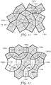
- FIG. 10 shows an exemplary group of connected octagons and squares 1060, 1060', 1060", 1060"' of connected cells 1040 and openings 1090a, 1090b, 1090c, 1090d.
- FIG. 11 shows an exemplary group of squares and triangles 1160, 1160', 1160", 1160"', 1160”" of connected cells 1140 and openings 1190a, 1190b, 1190c, 1190d, 1190e.
- FIG. 12 shows an exemplary array of mixed shapes 1260, 1260', 1260", 1260"', 1260"", 1260""'. 1260”"” of connected cells 1240 and openings 1290a, 1290b, 1290c, 1290d, 1290e, 1290f, 1290g.
- FIG. 13 shows an exemplary array of random shapes 1360, 1360', 1360", 1360"', 1360"", 1360”"' of connected cells 1340 and openings 1390a, 1390b, 1390c, 1390d, 1390e, 1390f.
- At least one of the first or second layer is free of openings.
- each cell has at least 3 (in some embodiments, at least 4, 5, 6, 7, 8, 9, or even at least 10) walls.
- each cell has a largest distance between two opposed walls of at least 3 mm (in some embodiments, at least 5 mm, 10 mm, 15 mm, 20 mm, 25 mm, or even at least 30 mm; in some embodiments, in a range from 3 mm to 30 mm, 7 mm to 30 mm, 15 mm to 30 mm, or even 20 mm to 30 mm).
- each cell has a largest distance between two opposed vertices of at least 5 mm (in some embodiments, at least 10 mm, 15 mm, 20 mm, 25 mm, 30 mm, 35 mm, or even at least 40 mm; in some embodiments, in a range from 15 mm to 40 mm, 20 mm to 40 mm, or even 30 mm to 40 mm).
- each cell has a distance from the second surface of the first layer to the first surface of the second layer of at least 2 mm (in some embodiments, at least 3 mm, 4 mm, 5 mm, 6 mm, 7 mm, 8 mm, 9 mm, 10 mm, or even at least 15 mm; in some embodiments, in a range from 4 mm to 15 mm, 7 mm to 15 mm, or even 10 mm to 15 mm).
- each cell has a volume of at least 0.04 cm 3 (in some embodiments, at least 0.1 cm 3 , 0.5 cm 3 , 1 cm 3 , 2 cm 3 , 3 cm 3 , 4 cm 3 , 5 cm 3 , 10 cm 3 , 15 cm 3 , 20 cm 3 , 25 cm 3 , or even at least 30 cm 3 ; in some embodiments, in a range from 0.04 cm 3 to 30 cm 3 , 0.1 cm 3 to 30 cm 3 , 0.5 cm 3 to 30 cm 3 , 2 cm 3 to 30 cm 3 , or even 15 cm 3 to 30 cm 3 ).
- a series of cells has a cumulative volume of at least 0.5 cm 3 (in some embodiments, at least 1 cm 3 , 1.5 cm 3 , 2 cm 3 , 3 cm 3 , 4 cm 3 , 5 cm 3 , 10 cm 3 , 25 cm 3 , 50 cm 3 , 75 cm 3 , 100 cm 3 , 150 cm 3 , or even at least 200 cm 3 ; in some embodiments, in a range from 1.5 cm 3 to 200 cm 3 , 10 cm 3 to 120 cm 3 , or even 50 cm 3 to 200 cm 3 ).
- a series of cells has a cumulative length of at least 20 mm (in some embodiments, at least 30 mm, 40 mm, 50 mm, 75 mm, 100 mm, 150 mm, or even at least 200 mm; in some embodiments, in a range from 30 mm to 200 mm, 50 mm to 200 mm, or even 100 mm to 200 mm).
- a series of cells of panels described herein has a cumulative length of at least 20 mm (in some embodiments, at least 25 mm, 30 mm, 40 mm, or even at least 50 mm).
- the first layer comprises at least one of polymeric, metallic, ceramic, or composite materials (e.g., fiber reinforced, woven or non-woven in a resin matrix).
- the second layer comprises at least one of polymeric, metallic, ceramic, or composite materials (e.g., fiber reinforced, woven or non-woven in a resin matrix).
- the core comprises at least one of polymeric, metallic, ceramic, or composite materials (e.g., fiber reinforced, woven or non-woven in a resin matrix).
- Exemplary polymeric materials include polyethylenes, polypropylenes, polyolefins, polyvinylchlorides, polyurethanes, polyesters, polyamides, polystyrene, copolymers thereof, and combinations thereof (including blends).
- the polymeric materials may be thermosetting by, for example, heat or ultraviolet (UV) radiation, or thermoplastic.
- Exemplary metallic materials include aluminum, steel, nickel, copper, brass, bronze, and alloys thereof.
- Exemplary ceramic (including glass, glass-ceramic, and crystalline ceramic) materials include oxides, nitrides, and carbides.
- Exemplary fiber containing materials include fibers such as cellulose, carbon, thermoplastic fibers (polyamide, polyester, and aramid, polyolefin), steel, and glass, as may be applicable to the particular type of material.
- materials for panels described herein may be in the form of multilayers.
- materials for panels described herein may also include fillers, colorants, plasticizers, dyes, etc., as may be applicable to the particular type of material.
- panels described herein have a single composition. Such embodiments are desirable to enhance recyclability.
- the first layer has a thickness of at least 0.01 mm (in some embodiments, at least 0.05 mm, 0.1 mm, 0.25 mm, 0.5 mm, 1 mm, 1.5 mm, 2 mm, 2.5 mm, or even at least 3 mm; in some embodiments, in a range from 0.025 mm to 0.5 mm, 0.1 mm to 2 mm, 0.25 mm to 3 mm or even 0.5 mm to 3 mm).
- the second layer has a thickness of at least 0.01 mm (in some embodiments, at least 0.05 mm, 0.1 mm, 0.25 mm, 0.5 mm, 1 mm, 1.5 mm, 2 mm, 2.5 mm, or even at least 3 mm; in some embodiments, in a range from 0.025 mm to 0.5 mm, 0.1 mm to 2 mm, 0.25 mm to 3 mm or even 0.5 mm to 3 mm).
- panels described herein have a thickness of at least 4 mm (in some embodiments, at least 7 mm, 10 mm, or even at least 15 mm; in some embodiments, in a range from 4 mm to 8 mm, 6 mm to 10 mm, or even 8 mm to 15 mm).
- the cell walls have a thickness of at least 0.01 mm (in some embodiments, at least 0.05 mm, 0.1 mm, 0.2 mm, or even at least 0.5 mm; in some embodiments, in a range from 0.01 mm to 0.2 mm, 0.05 mm to 0.5 mm, or even 0.1 mm to 0.5 mm).
- the first series of cells comprises at least 4 (in some embodiments, at least 5, 6, 7, 8, 9, 10, 11, 12, 13, 14, 15, 16, 17, 18, 19, 20, 21, 22, 23, 24, 25, 26, 27, 28, 29, 30 or more) cells.
- panels described herein further comprising a second series of at least 3 (in some embodiments, at least 4, 5, 6, 7, 8, 9, 10, 11, 12, 13, 14, 15, 16, 17, 18, 19, 20, 21, 22, 23, 24, 25, 26, 27, 28, 29, 30 or more) cells.
- panels described herein further comprising a third series of at least 3 (in some embodiments, at least 4, 5, 6, 7, 8, 9, 10, 11, 12, 13, 14, 15, 16, 17, 18, 19, 20, 21, 22, 23, 24, 25, 26, 27, 28, 29, 30 or more) cells.
- panels described herein further comprising a tie layer on at least a portion of the second of the major surface of the first layer. In some embodiments, panels described herein further comprising a tie layer on at least a portion of the first of the major surface of the second layer.
- the tie layer is believed to facilitate adhesion between first or second layer 110, 130 and core layer 120.
- the same polymer used for the skin and core may also be used as the tie layer. This approach forms a desirable recyclable panel as all components have substantially the same composition (i.e., at least 85 percent by weight is the same composition).
- similar polymers for both the core and skins can be used.
- additives to slow the crystallization rate and/or reduce the viscosity of the tie layer may be used. These minor additives desirably do not affect the recycling of polymers.
- additives that promote a chemical bond between the tie layer and the skin and/or the core can be employed.
- block copolymers can be useful where the copolymer has blocks containing polymers with affinity for the skin and blocks with affinity for the core.
- techniques for compatibilizing incompatible polymer blends may be useful.
- hot melt adhesives, pressure sensitive adhesives and/or curable adhesives may be used.
- panels described herein exhibit indicia (including alphanumerics).
- the indicia is in the form of a trademark or copyrighted material, including a registered trademark or registered copyright as defined under any of the countries, territories, etc., of the world (including the United States).
- the indicia is on at least one of the first major surface of the first layer, on the second major surface of the second layer.
- the panel is in the form of the indicia.
- panels described herein exhibit at least one absorption band less than 1400 Hz (in some embodiments, less than 1300 Hz, or even less than 1200 Hz). In some embodiments, panels described herein exhibit at least one absorption band in a range from at least 800 Hz to 1200 Hz (in some embodiments, in a range from at least 500 Hz to 1300 Hz, at least 200 Hz to 1400 Hz, or even at least 20 Hz to 1400 Hz).
- the absorption bands of panels described herein are measured as described in the Examples using the "Normal Incidence Acoustical Absorption Test" and the "Reverberation Chamber Test.”
- panels (or articles comprising one or more panels) described herein have a thickness in a range from 4 mm to 8 mm, 6 mm to 10 mm, or even 8 mm to 15 mm, and exhibiting at least one absorption band less than 1400 Hz (in some embodiments, less than 1300 Hz or even less than 1200 Hz).
- panels (or articles comprising one or more panels) described herein have a thickness in a range from 4 mm to 8 mm, 6 mm to 10 mm, or even 8 mm to 15 mm, and exhibiting at least one absorption band in a range from at least 800 Hz to 1200 Hz (in some embodiments, in a range from at least 500 Hz to 1300 Hz, at least 200 Hz to 1400 Hz, or even at least 20 Hz to 1400 Hz).
- each of Examples 5 and 6, described below include panels comprising a thickness of less than 15 mm (more particularly 6.2 mm) and exhibit at least one absorption band less than 1400 Hz.
- laminated articles described herein comprising at least two panels laminated together (or three, four, five, or more stacked panels laminated together) have a thickness in a range from 8 mm to 50 mm, 10 mm to 30 mm, or even 12 mm to 40 mm, and exhibiting at least one absorption band in a range from at least 600 Hz to 1000 Hz (in some embodiments, in a range from at least 500 Hz to 1300 Hz, at least 200 Hz to 1400 Hz, or even at least 20 Hz to 1400 Hz).
- panels described herein exhibit an acoustical absorption of at least 50 (in some embodiments, at least 55, 60, 65, 70, 75, or even 80) percent.
- the acoustical absorption of panels described herein are measured as described in the Examples using the "Normal Incidence Acoustical Absorption Test” and the “Reverberation Chamber Test.”
- panels described herein exhibit a flexural rigidity of at least 1 N-m 2 (in some embodiments, at least 5 N-m 2 , 10 N-m 2 , 15 N-m 2 , 20 N-m 2 , 25 N-m 2 , 30 N-m 2 , 35 N-m 2 , 40 N-m 2 , 45 N-m 2 , 50 N-m 2 , 55 N-m 2 , or even 60 N-m 2 ) per meter of width.
- the flexural rigidity of panels described herein are measured as described in the Examples using the "3 Point Flexure Test.”
- panels described herein exhibit a compression strength of at least 0.35 MPa (in some embodiments, at least 0.5 MPa, 1 MPa, 1.5 MPa, 2 MPa, 3 MPa, or even 4 MPa).
- the compression strength of panels described herein are measured as described in the Examples using the "Compression Test.”
- panels (or articles comprising one or more panels) described herein exhibit both a flexural rigidity of at least 1 N-m 2 (in some embodiments, at least 5 N-m 2 , 10 N-m 2 , 15 N-m 2 , 20 N-m 2 , 25 N-m 2 , 30 N-m 2 , 35 N-m 2 , 40 N-m 2 , 45 N-m 2 , 50 N-m 2 , 55 N-m 2 , or even 60 N-m 2 ) per meter of width and at least one absorption band less than 1400 Hz (in some embodiments, less than 1300 Hz or even less than 1200 Hz).
- panels (or articles comprising one or more panels) described herein exhibits both a flexural rigidity of at least 1 N-m 2 (in some embodiments, at least 5 N-m 2 , 10 N-m 2 , 15 N-m 2 , 20 N-m 2 , 25 N-m 2 , 30 N-m 2 , 35 N-m 2 , 40 N-m 2 , 45 N-m 2 , 50 N-m 2 , 55 N-m 2 , or even 60 N-m 2 ) per meter of width and at least one absorption band in a range from at least 800 Hz to 1200 Hz (in some embodiments, in a range from at least 500 Hz to 1300 Hz, at least 200 Hz to 1400 Hz, or even at least 20 Hz to 1400 Hz).
- Examples 5 and 6, described below includes panels exhibiting both a flexural rigidity of at least 1 N-m 2 per meter of width and at least one absorption band less than 1400 Hz.
- the frequency of the peak absorption decreases; 2) as the skin hole size (whether provided by one hole or multiple holes) increases, the frequency of the peak absorption increases; 3) as the width of the cell decreases, more cells need to be connected to exhibit absorption at the same frequency; 4) as the cell height decreases, the frequency of the peak absorption increases; 5) as the passageway size decreases, the frequency of the peak absorption decreases (plus with less total absorption and narrower absorption peaks); and 6) as the skin thickness increases, the frequency of peak absorption decreases.
- multiple variables can be adjusted to optimize (e.g., tune) the acoustic absorption of a panel or article for a particular end use application.
- the present disclosure describes a panel comprising first, second, and third layers, each of the first, second, and third layers having first and second opposed major surfaces and a core disposed there between, the second layer being free of any openings between the first and second major surfaces of the second layer, wherein the core has a plurality of walls extending from the second surface of the first layer to the first surface of the second layer providing a series of connected cells and a plurality of walls extending from the second surface of the second layer to the first surface of the third layer, wherein some of the cell walls have openings providing fluid communication between a series of at least 3 cells, wherein each cell wall has a plurality of sides, wherein each side of a cell wall has an area, and wherein the opening in a cell wall has an area that is at least 50 percent of the area of a side of that cell wall, and wherein the first layer has at least a first opening extending between the first and second major surfaces of the first layer into at least one cell in the series.
- the panel further comprises a fourth layer, the fourth layer having first and second opposed major surfaces and a core disposed there between, the fourth layer being free of any openings between the first and second major surfaces of the fourth layer.
- any number of layers may be included in the panels: four, five, six, seven, eight, nine, ten, etc.
- the present disclosure describes an article comprising a panel comprising first and second layers each having first and second opposed major surfaces and a core disposed there between, the second layer being free of any openings between the first and second major surfaces of the second layer, wherein the core has a plurality of walls extending from the second surface of the first layer to the first surface of the second layer providing a series of connected cells, wherein some of the cell walls have openings providing fluid communication between a series of at least 3 cells, wherein each cell wall has a plurality of sides, wherein each side of a cell wall has an area, and wherein the opening in a cell wall has an area that is at least 50 percent of the area of a side of that cell wall, and wherein the first layer has at least a first opening extending between the first and second major surfaces of the first layer into at least one cell in the series, wherein the panel is a flat panel or a shaped panel.
- Exemplary embodiments of panels described herein can be formed articles such as automotive parts, such as engine covers, wheel well liners, underbody shields, headliners, trunk covers, floor mats, carpet backings, hood liners, and tonneau covers, housings for generators, motors, appliances, tools, etc., and in general, any item emitting sound; architectural walls, panels, floors, doors, enclosures, ducts, sound barriers, etc., aircraft, watercraft, trucks, trains, agricultural equipment, fork lifts, and trailers.
- automotive parts such as engine covers, wheel well liners, underbody shields, headliners, trunk covers, floor mats, carpet backings, hood liners, and tonneau covers, housings for generators, motors, appliances, tools, etc., and in general, any item emitting sound; architectural walls, panels, floors, doors, enclosures, ducts, sound barriers, etc., aircraft, watercraft, trucks, trains, agricultural equipment, fork lifts, and trailers.
- the article When the article is a housing of an item that emits sound, the article typically absorbs at least one acoustical frequency (emitted from the item) of less than 1400 Hz (in some embodiments, less than 1300 Hz or even less than 1200 Hz).
- the present disclosure describes a method of absorbing at least one acoustical frequency below 1400 Hz by disposing an article adjacent to an item that emits at least one acoustical frequency below 1400 Hz (in some embodiments, less than 1300 Hz or even less than 1200 Hz), wherein the article comprises at least one panel comprising first and second layers each having first and second opposed major surfaces and a core disposed there between, the second layer being free of any openings between the first and second major surfaces of the second layer, wherein the core has a plurality of walls extending from the second surface of the first layer to the first surface of the second layer providing a series of connected cells, wherein some of the cell walls have openings providing fluid communication between a series of at least 3 cells, wherein each cell wall has a plurality of sides, wherein each side of a cell wall has an area, and wherein the opening in a cell wall has an area that is at least 50 percent of the area of a side of that cell wall, and wherein the first
- the article comprises an enclosure at least partially surrounding the item that emits at least one acoustical frequency below 1400 Hz, while in others the article comprises a housing of the item that emits at least one acoustical frequency below 1400 Hz.
- the article is an automotive part, such as the parts disclosed above.
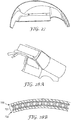
- FIG. 28A shows a roof area of an automobile
- FIG. 28B shows a cross-sectional view of a portion of an exemplary headliner. More particularly, a panel according to at least certain embodiments of the present disclosure is shaped, such as to have the curve of the panel 701 shown in FIG. 28B .
- the figure shows the roof 700 and the fabric or non-woven liner 702 adjacent or adhered to the panel 701.
- FIG. 24 an exemplary underbody shield is shown. Examples 10-11 below describe the preparation of exemplary underbody shields comprising shaping panels according to the present disclosure.
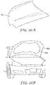
- FIG. 36B an exemplary hood liner 999 is shown attached to the underside of an automotive hood 998.
- FIG 36A shows a schematic perspective view of the top of an automotive hood 33a.
- Suitable polymers include for instance and without limitation, polyamides including PA6, PA66, polybutylene terephthalate (PBT), poly ethylene terephthalate (PET), poly ethylene naphthalate (PEN), polyphenylene sulfide (PPS), Polyether imide (PEI), Polyether sulfone (PES), Polyether ketone (PEK) and Polyether ether ketone (PEEK) and fluoropolymers.
- polyamides including PA6, PA66, polybutylene terephthalate (PBT), poly ethylene terephthalate (PET), poly ethylene naphthalate (PEN), polyphenylene sulfide (PPS), Polyether imide (PEI), Polyether sulfone (PES), Polyether ketone (PEK) and Polyether ether ketone (PEEK) and fluoropolymers.
- additives such as flame retardants are typically added to heat resistant polymeric materials to provide further protection during high temperature applications.
- Useful flame retardants include for instance and without limitation, inorganics such as alumina trihydrate (ATH), huntite and hydromagnesite, various hydrates, phosphorus, boron compounds, antimony trioxide and pentoxide and sodium antimonate; halogenated compounds such as organochlorines including chlorendic acid derivatives and chlorinated paraffins; organobromines such as decabromodiphenyl ether (decaBDE), decabromodiphenyl ethane, polymeric brominated compounds, brominated carbonate oligomers (BCOs), brominated epoxy oligomers (BEOs), tetrabromophthalic anyhydride, tetrabromobisphenol A (TBBPA) and hexabromocyclododecane (HBCD); organophosphates such as triphenyl phosphate (TPP),
- the engine cover optionally has a design resembling FIGS. 25A-25D .
- a ridge is formed in the panel for aesthetic or structural purposes by shaping the panel out of the plane and compressing its thickness as shown as C-C' in the figures.
- the honeycomb core can be completely collapsed so that the top and bottom skins are in contact, then trimmed (e.g., with a rotary tool, a laser or a water jet) for a clean edge that does not show the honeycomb core.
- injection over-molding can be employed to produce attachment points shown as D, D', D" and D'" in FIGS. 25C and 25D .
- ribs may be molded against the panel for additional stiffening and/or aesthetic reasons.
- An exemplary rib is depicted in FIG. 25D , shown as rib E-E'.
- the acoustical spectrum of an engine depends on many factors including engine design, load and rotations per minute (rpm).
- the panels according to the present disclosure may thus need to be tuned to several prominent frequencies.
- An acoustical panel may be thermoformed as described below in Example 10, then inserted into an injection mold for the attachments and ribbing to be overmolded on the panel.
- the panel may be preheated outside of the injection mold and the closing of the injection mold shapes the panel, such that the overmolding occurs in a single machine.
- Tire noise is a major contributor to automotive noise. It can be advantageous to absorb this noise close to the source, e.g., the contact patch between the tire and the roadway.
- Fender liners are thus a useful application for panels according to aspects of this disclosure. Not only does the sound reaching the cabin get reduced, but also some sound that would otherwise reflect off a solid fender liner and remain in the environment is reduced by the panel absorption.
- thermoforming, compression molding and injection molding may all be employed in producing these parts.
- An exemplary wheel-well liner in shown in FIG. 27 .
- Panels according to at least certain aspects of this disclosure can be used in the flooring of the vehicle, again in a position between the roadway (e.g., a major noise source) and the occupant(s) of the vehicle.
- a floor pan of the vehicle could be made of the panels, such as by laminating multiple panels and/or using fiber reinforced or metal stiff skins to provide the rigidity to no longer necessitate use of metal flooring.
- a floor mat (see, e.g., the exemplary floor mat 2900 depicted in a vehicle in FIG. 29 ) may be made of an elastomeric or flexible plastic or rubber. An exemplary floor mat design is shown in FIG 30A .
- the solid skin layer 810 could be positioned toward an occupant so that dirt and sand do not enter the panel and the surfaces may be wiped or washed clean.
- An additional layer 840 may also be used that potentially has advantageous features such as a designed level of friction, easy clean composition, and abrasion resistance.
- the skin layer with the holes or perforations 810 faces the sound source (e.g., the road).
- a laminated panel could be used with holes facing the road and the occupants. In the latter case, a second chance for absorption within the cabin of the vehicle can further reduce the noise level.
- FIG. 30B another design is depicted that could either comprise a floor mat or carpeting in the vehicle.
- the additional layer 850 is an adhesive or tie layer and the layer 860 is carpeting.
- the present disclosure describes a laminated article comprising first and second panels, each of the first and second panels comprising first and second layers each having first and second opposed major surfaces and a core disposed there between, the second layer being free of any openings between the first and second major surfaces of the second layer, wherein the core has a plurality of walls extending from the second surface of the first layer to the first surface of the second layer providing a series of connected cells, wherein some of the cell walls have openings providing fluid communication between a series of at least 3 cells, wherein each cell wall has a plurality of sides, wherein each side of a cell wall has an area, and wherein the opening in a cell wall has an area that is at least 50 percent of the area of a side of that cell wall, and wherein the first layer has at least a first opening extending between the first and second major surfaces of the first layer into at least one cell in the series, wherein the second surface of the second layer of the first panel is directly attached to the first surface of either the first layer or the second layer of the second
- the laminated article further comprises a third panel, the third panel comprising first and second layers each having first and second opposed major surfaces and a core disposed there between, the second layer being free of any openings between the first and second major surfaces of the second layer, wherein the core has a plurality of walls extending from the second surface of the first layer to the first surface of the second layer providing a series of connected cells, wherein some of the cell walls have openings providing fluid communication between a series of at least 3 cells, wherein each cell wall has a plurality of sides, wherein each side of a cell wall has an area, and wherein the opening in a cell wall has an area that is at least 50 percent of the area of a side of that cell wall, and wherein the first layer has at least a first opening extending between the first and second major surfaces of the first layer into at least one cell in the series, wherein the second surface of the second layer of the first panel is directly attached to the first surface of the first layer of the second panel, and wherein the second surface of the second layer of the second layer of
- thermoforming includes heating the panel and applying force to shape the panel against at least one tool. Typically the panel is heated to a processing temperature where it becomes compliant. The panel is then positioned within a mold, between 2 platens prior to the platens closing. The panel is shaped by mechanical force from the tool, or by vacuum or pneumatic pressure followed by a cooling period to return the panel to a rigid structure.
- Exemplary polypropylene (PP) panels can be thermoformed, for example, with the panel pre-heat temperature of 310-350°F (154-177°C), mold temperature of 150°F (66°C), clamping force of 4,000 lbs. (1,814 kgf) and cooling time of 30 seconds.
- the present disclosure describes a method of making an article, the method comprising: pre-heating a panel; placing the panel proximate to a thermoforming mold; and applying vacuum to shape the panel to provide the article.
- the present disclosure describes a method of making an article, the method comprising: pre-heating a panel; placing the panel between matched halves of a (e.g., thermoforming) mold; and applying pressure to close the mold and shape the panel to provide the article.
- a e.g., thermoforming
- Another method for making articles from panels described herein comprises shaping a panel described herein via insert molding to provide the article.
- the mold closing action forms the panel into a three dimensional shape while the overmolded plastic may produce additional features such as fastening points, ribbing or other structural/cosmetic features.
- the mold closing force may be enough to shape the panel, or thermoforming/compression molding performed prior to insert molding may be required; in either case, pre-heating the formed panel may not be necessary.
- a method comprising placing at least a portion of a panel in an injection molding die; and overmolding at least one mold structure on a surface of the panel in the injection molding die, thereby forming a material-to-material connection between the surface of the panel and the mold structure.
- the method optionally further comprises at least partially shaping a (flat) panel using thermoforming or compression molding prior to placing at least a portion of the panel within the injection molding die, e.g., using vacuum, pressure, or match metal shaping to shape the panel.
- Some exemplary mold structures comprise at least one (molded) bushing, lock housing, fixture mechanism, receptacle, or lock receptacle region.
- Suitable materials for a mold structure are not particularly limited, and include each of a thermoset material, a thermoplastic material, a photocurable material, and a bulk metallic glass (e.g., an amorphous alloy). Mold structures can be applied to any portion of a panel, such as on at least one major surface of the panel, an edge of the panel, or a shaped part of the panel. Additionally, at least one profile element may be molded directly onto the mold structure, on an edge side of the panel, or both.
- the injection molding die is configured to reduce or increase a thickness of at least a portion of the panel or of the entire panel by 5% to 95% or to increase a thickness of at least a portion of the panel by 5% to 50%.
- the injection molding die may be shaped to reduce the thickness of a portion or all of a panel by 5% or more, 10% or more, 15% or more, 20% or more, 25% or more, 30% or more, 35% or more, 40% or more, 45% or more, 50% or more, 55% or more, or even 60% or more; and 95% or less, 90% or less, 85% or less, 80% or less, 75% or less, 70% or less, or 65% or less.
- the decrease in thickness is a decrease in the thickness of the core of the panel.
- the injection molding die may be shaped to increase the thickness of a portion or all of a panel by 5% or more, 10% or more, 15% or more, 20% or more, 25% or more, or even 30% or more; and 50% or less, 45% or less, 40% or less, or 35% or less.
- Increasing the thickness of a panel may involve pulling a vacuum in the injection molding die to draw out the panel material.
- the entire panel is inserted into the injection molding die.
- a thermoplastic material may be injection molded around the panel to form the mold structure.
- the panel is optionally preheated prior to placing it within the injection molding die.
- a panel undergoing overmolding may be flat or alternatively comprise a (e.g., three dimensional) shape.
- the method may further comprise altering the shape of the panel (e.g., "reshaping" the panel) in the injection molding die.
- at least one cell is consolidated and folded over to form a reinforcement bead. When a number of adjacent cells are consolidated and folded over they can form a "hem" having a thickness approximately equal to twice the thickness of the first and second layers of the panel.
- Another method for making articles from panels described herein comprises shaping a panel described herein via compression molding to provide the article.
- putting a panel inside of a mold between 2 platens, heating the mold, closing the platens to shape the panel while maintaining pressure during a mold cooling stage provides the article.
- the panel must be pre-heated prior to closing the mold to ensure material compliance.
- Exemplary polypropylene (PP) panels can be compression molded, for example, without panel pre-heating, thermal cycling mold temperatures of 305°F (152°C) and 150°F (66°C), clamping force of 30,000 lbs. (13,607 kgf) and cooling/pressure holding time of 30 seconds.
- Another method for making articles from panels described herein comprises:
- laminating the first layer to the core occurs during extrusion of the core.
- a film die can be configured to drop the extrudate into the first nip of a 3-roll stack, such that it is between the skin film and the tooling (middle) roll. The extrudate will solidify while in contact with the tooling roll, and adhere to the first layer. After travelling about 180° around the tooling roll, the first layer side contacts the silicone (third) roll. A belt puller located beyond the silicone roll can be used to control the pulling with a force sufficient to remove the solidified extrudate from the tooling roll. The second layer may be unwound over the top of the belt puller and continuously contacting the top belt.
- a molten tie layer can be delivered (e.g., from a film die connected to another extruder) onto the top of the open honeycomb just prior to contacting the second layer in the entrance to the belt puller.
- the tie layer solidifies, bonding the honeycomb to the second layer while being held flat by the belt puller.
- a panel with first and second layers adhered to the core exits the belt puller.
- an adhesive may be used to laminate the first and second layers to the extruded core.
- two tie layers may be used to laminate the first and second layers to the extruded core.
- thicker panels for example, either for increased mechanical rigidity or lower frequency absorption. It is possible to combine two panels into a thicker one in several configurations and by several methods. For example, in FIG. 31 , two panels may be positioned so that the honeycomb walls align in the thickness direction and the panels are welded together. As used herein, “weld” refers to the attachment of two polymeric materials using heat. The heat may be provided through various mechanisms, including for instance and without limitation, conduction, vibration, oscillation, radiant energy (e.g., laser or infrared energy), or convection of a fluid.
- radiant energy e.g., laser or infrared energy
- two polymeric materials are welded together by applying heat to a surface of each of the materials, bringing the two heated surfaces together, and allowing the heated surfaces to cool and form a bond, such as through entanglement of polymers from each surface.
- Pressure is usually applied to hold the two polymeric materials together and promote the formation of a weld between the two polymeric materials as they cool.
- the present disclosure describes a method of making a laminated article comprising first and second panels, the method comprising welding the first and second panels together, wherein each of the first and second panels comprise first and second layers each having first and second opposed major surfaces and a core disposed there between, the second layer being free of any openings between the first and second major surfaces of the second layer, wherein the core has a plurality of walls extending from the second surface of the first layer to the first surface of the second layer providing a series of connected cells, wherein some of the cell walls have openings providing fluid communication between a series of at least 3 cells, wherein each cell wall has a plurality of sides, wherein each side of a cell wall has an area, and wherein the opening in a cell wall has an area that is at least 50 percent of the area of a side of that cell wall, and wherein the first layer has at least a first opening extending between the first and second major surfaces of the first layer into at least one cell in the series, wherein the second surface of the second layer of the first panel is
- the welding comprises: bringing the second surface of the second layer of the first panel to a temperature above the melting point of the second surface of the second layer of the first panel; bringing the first surface of the first layer of the second panel to a temperature above the melting point of the first surface of the first layer of the second panel; and holding the second surface of the second layer of the first panel in contact with the first surface of the first layer of the first surface of the second panel to form a bond between the first panel and the second panel as each of the second surface of the second layer of the first panel and the first surface of the first layer of the first surface of the second panel cools.
- adhesives may be used to join two or more panels together.
- Pressure sensitive or structural adhesives may be used depending on the required properties of the finished article.
- the adhesives may by triggered by radiation, such as including ultraviolet, visible, infrared, gamma, or e-beam, or by heating to effect curing. Contact pressure may be sufficient for the pressure sensitive adhesives.
- Another alternative includes using an extruded tie layer of the same polymer composition to bond two panels together in a continuous process. Preheating of the pre-made panel surfaces and/or a sufficiently high tie layer temperature may be required to provide an adequate bond between the panels.
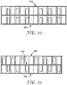
- FIGS. 31-33 depict some possible geometries.
- FIG. 31 depicts two panels with the honeycomb walls aligned in the thickness direction and the hole from the top skin 990 extends through the middle layers 992 to interconnect channels.
- the holes do not have to be of the same size. This is useful to absorb lower frequencies by doubling the length and the volume of the channels.
- FIG. 32 shows two panels aligned like FIG. 31 , with a hole in the top skin 993 and one in the bottom skin 995, but there are no holes interconnecting the top and bottom panels.
- the stiffness of the panel is increased, and sound may be absorbed that is incident on either side of the panel.
- the channel lengths and volumes are not doubled.
- the hole sizes or perforations in each skin can be of different sizes to tune each side of the panels to a different frequency band. It should be noted that 3, 4, 5 or even 10 or more panels could be connected by welding or adhesives to make a single thicker laminated article.
- the present disclosure describes a method of making an article, the method comprising: obtaining first and second panels; contacting the first and second panels such that the core of the first panel is aligned with the core of the second panel; and holding the first panel and the second panel in contact to form a bond between the core of the first panel and the core of the second panel as the first and second panels cool to form the article, wherein the core of the first panel and the core of the second panel together form a core disposed between the layer of the first panel and the layer of the second panel.
- the heating is typically provided by conduction, vibration, oscillation, radiant energy, or convection of a fluid.
- the method is a continuous method of forming the article whereas in other embodiments the method is a batch method of forming the article.
- FIG. 33 shows two panels with one of them flipped over 180 degrees.
- the honeycomb walls are not likely to be aligned in this case, so some channels will be very short and of low volume, while others may be longer and still other may have a hole in both the top and bottom skin.
- the present disclosure describes a method of making a panel, the method comprising: generating a panel by an additive manufacturing method; wherein the panel comprises first and second layers each having first and second opposed major surfaces and a core disposed there between, the second layer being free of any openings between the first and second major surfaces of the second layer, wherein the core has a plurality of walls extending from the second surface of the first layer to the first surface of the second layer providing a series of connected cells, wherein some of the cell walls have openings providing fluid communication between a series of at least 3 cells, wherein each cell wall has a plurality of sides, wherein each side of a cell wall has an area, and wherein the opening in a cell wall has an area that is at least 50 percent of the area of a side of that cell wall, and wherein the first layer has at least a first opening extending between the first and second major surfaces of the first layer into at least one cell in the series.
- the opposed first major surface is obtained and the remainder of the panel is generated on the first major surface by the additive manufacturing method.
- the entire panel is generated by the additive manufacturing method.
- the additive manufacturing process comprises a layer-by-layer process.
- the present disclosure describes a method of manufacturing an article, the method comprising: modeling an acoustical performance and a structural performance of a plurality of walls forming interconnected channels within the core of a panel; and producing the article comprising a plurality of the walls having the acoustical performance, the structural performance, or both, by an additive manufacturing method.
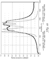
- ASTM E-1050 (2008) was employed to measure the acoustic absorption with normal incidence acoustic wave.
- a 100 mm inner diameter impedance tube obtained from Bruel & Kjaer, Naerum, Denmark, under the trade designation "Impedance Tube Kit Type 4206" was used.
- a speaker obtained from Bruel & Kjaer, as Impedance Tube Kit Type 4206 was used to generate broad band frequency from 10 Hz to 6400 Hz at one end of the tube with the test specimen in place at the other end.
- the specimen was mounted so as to touch the hard wall on the back side of the impedance tube, with the side of the specimen having holes facing the noise source.
- SAE Test Method J2883 (2015) was used to measure the acoustic absorption of a material in a diffused field in which sound comes from random directions (0° to 180° angle of incidence) measured in a reverberation chamber (obtained from Autoneum, Winterthur, Switzerland, under the trade designation "ALPHA CABIN”). Specifically, the three speakers in the reverberation chamber were used to generate one third or one twelfth center frequency tones from 400 Hz to 10,000 Hz and five microphones (obtained from PCB Piezotronics, Buffalo, NY, as Type 130E20) were used to measure the sound pressure levels in the reverberation chamber. Each microphone measured how fast the noise decayed in time.
- test specimens were tested in compression, following ASTM C 365 / C 365 M (2005). Specifically, test specimens were cut in length and width to 1.5 inch x 1.5 inch (38 mm x 38 mm) and the thickness was measured for each specimen. Thicknesses were about 0.25 inch (6.35 mm). The test apparatus' 15.24 cm (6 inch) diameter parallel plates were compressed together at 0.2 in./min. (5.08 mm/min.). The machine compliance (deflection as a function of load) correction was used to calculate the sample strain in the modulus calculation. The test was carried out to a maximum load of at least 34 kN. This occurred at greater than 60% strain (sample thickness up to 40% of the original thickness). The compression strength is reported as the peak load at yield. The yield strain occurred at 6-11% strain.
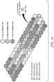
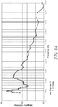
- FIG. 14 shows the pattern of connected hexagons and holes located that were both modeled and 3D-printed.
- Each specimen had two sets of 5 connected hexagons (1460, 1460'), a first pair of 6 connected hexagons (1470, 1470'), a second pair of 6 connected hexagons (1471, 1471'), and three sets of 7 connected hexagons (1480, 1480', 1480").
- the upper skin was printed to leave holes (see FIG. 14 , 1460a through 1480c) in the upper skin (and Table 1, below).
- Example 1 and 3 specimens were tested, and then the holes were expanded by drilling to create additional Example 2 and 4 specimens, which were also tested.
- Table 1, above, shows the dimensions of the "original” and “larger” hole sizes for Examples 1-4.
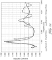
- FIGS. 15 and 16 show the acoustical absorption coefficient modeled and measured using the Normal Incidence Acoustical Absorption Test for the 10 mm tall cell walls with the "original" (Example 1) and “larger” (Example 2) hole sizes, respectively.
- FIGS. 17 and 18 show the acoustical absorption coefficient modeled and measured using the Normal Incidence Acoustical Absorption Test for the 12.7 mm tall cell walls with the "original" (Example 3) and “larger” (Example 4) hole sizes, respectively.
- a honeycomb panel with 11.5 mm hexagonal cells was prepared by extrusion replication lamination, then passageways were machined to make a number of linear chambers of 5 hexagons and 7 hexagons, and twice as many chambers of 6 hexagons. Holes were drilled in the top skin, then the bottom skin was laminated in a dual belt laminator. Details of the acoustical panel preparation are given below.
- a 35 wt. % glass-fiber filled polypropylene (GFPP) resin (obtained under the trade designation "XMOD GB306” from Borealis, Vienna, Austria) was extruded in a 2.5 inch (6.25 cm) extruder (obtained under the trade designation “NRM” from Davis-Standard, Pawcatuck, CT) at a screw speed of 90 rpm, and with barrel zones ramped up, from the feed end to the discharge end, from 290°F (143°C) to 460°F (238°C). An 18 inch (457 mm) film die at 460°F (238°C) was used to drop the extrudate into a three-roll stack.
- GFPP glass-fiber filled polypropylene
- the extrudate was nipped between a first chrome roll at 90°F (32°C) and a second chrome roll at 120°F (49°C) and stripped off the second chrome roll to a silicone rubber roll at 90°F (32°C).
- the line speed was 10 feet/minute and the resulting 0.023 inch (0.58 mm) thick GFPP film was wound onto 6 inch (13.5 cm) outside diameter cores.
- the film described above was unwound into the nip of the three-roll stack casting station, but with the center chrome roll replaced by a tooling roll that had multiple 11.5 mm connected hexagons (width dimension) cut 0.30 inch (7.6 mm) deep into its surface.
- the grooves forming the hexagonal pattern had a draft angle of 2° and were 0.024 inch (0.6 mm) wide at the bottom and 0.51 inch (1.3 mm) wide at the roll surface.
- Polypropylene resin obtained under the trade designation "PRO-FAX 8523” from LyondellBasell, Rotterdam, Netherlands was fed to the extruder ("NRM"), operated at 48 rpm, with barrel zone temperatures ramped from 350°F (177°C) to 450°F (232°C).
- the film intended to become a skin layer, had about 90 degrees of wrap on the chrome nip roll that was set to 150°F (66°C) and the gap between this roll and the tooling roll was 0.043 inch (1.09 mm).
- the line speed was 3 feet/minute (0.91 m/min.) and the honeycomb tooling roll was set to 200°F (93°C).
- the film die was set to 430°F (221°C), and was configured to drop the extrudate into the nip such that it was between the skin film and the tooling roll.
- the extrudate crystallized while in contact with the tooling roll, and after travelling about 180° around the tooling roll, the skin side contacts the silicone (third) roll.
- a belt puller located beyond the silicone roll was used to control the pulling force at 250 lbs. (1110 N); a force sufficient to remove the solidified extrudate from the tooling roll onto the silicone roll, but insufficient to elongate (distort) the hexagonal geometry.
- the honeycomb, adhered to the GFPP bottom skin, was measured to have 0.270 inch (6.86 mm) wall height.
- a second GFPP film intended to be the second skin was unwound over the top of the belt puller and continuously contacted the top belt.
- a molten tie layer of the polypropylene (“PROFAX 8523”) was extruded, using a 1.5 inch (3.75 cm) extruder (obtained from Davis-Standard) operating at 50 rpm, onto the top of the open honeycomb just prior to contacting the top skin in the entrance to the belt puller.
- the barrel temperatures of the tie layer extruder were ramped from 280°F (138°C) to 500°F (260°C) and the die was set to 550°F (288°C).
- the resulting panel was 0.30 inch (7.6 mm) thick.
- FIG. 19 There are twice as many sets of 6-connected cells as 5-connected cells and 7-connected cells.
- FIG. 19 shows only a portion of the panel, which extended in both length and width. Holes were then drilled through the bottom skin at locations indicated in FIG. 19 , and the hole diameters are listed in FIG. 19 .
- a new top skin was laminated to the workpiece having the drilled bottom skin and honeycomb walls, using a dual belt laminator (obtained under the trade designation "KFK-E 1500" from Meyer Co., Riverside, CT).
- a 0.5 mm thick skin, as described in the skin preparation section, was fed onto the bottom belt along with 0.8 mm impact-polypropylene sheeting (obtained under the trade designation "MC100-F” from Optimum Plastics, Bloomer, WI), which was in contact with the honeycomb so as to serve as a sealing layer.
- the belt speed was 3 fpm (0.9 m/min.), the bottom belt was set to 180°C, the top belt was set to 130°C, the belt gap was set to 6.5 mm, and the nip was fixed at 0.1 mm.
- the cross-section of the laminated panel is shown in FIG. 20 , with the laminated new skin shown as being on the bottom of the structure.
- Example 5 Three panels, made as above, were then taped together to form a 1118 mm x 990 mm panel (Example 5) and measured for random incidence acoustical absorption using the Reverberation Chamber Test. Following this measurement, the holes labelled A and C in FIG. 19 , in the 3 panels of the specimen of Example 5, were re-drilled for the set of 5 connected cells from 0.1495 inch (3.80 mm) to 0.359 inch (9.12 mm) and for one of the sets of 6 connected cells from 0.166 inch (4.22 mm) to 0.359 inch (9.12 mm) to produce the specimen for Example 6.
- FIG. 21 shows the geometry of the hexagons relative to the edge of the panel.
- An area correction was applied to the acoustical absorption coefficient plotted vs. frequency in FIG. 22 .
- a clear peak centered at about 1000 Hz is seen for the specimen of Example 5.
- a second peak is found at 1320 Hz for the specimen of Example 6 (with its enlarged holes).
- honeycomb panels about 39 inch x 15 inch (1143 x 432 mm), produced as described above, were machined in the vertical machining center.
- a panel was first mounted using double stick tape. Then, the top skin was removed and a 7/32 inch (5.55 mm) ball end mill was used to remove honeycomb walls to within 0.015 inch (0.38 mm) of the bottom skin.
- the pattern of interconnected hexagons was changed to be the nested hexagon array shown in FIG. 1 . There are two sets of 5 interconnected hexagons, two sets of 6 interconnected hexagons and two sets of 7 interconnected hexagons in the larger 37 hexagon repeat unit that was repeated in these panels.
- Hexes 6 Hexes 7 Hexes 7 2 mm (0.079 inch) 2 mm (0.079 inch) 2 mm (0.079 inch) 8 3 mm (0.118 inch) 2 mm (0.079 inch) 2 mm (0.079 inch) 9 4 mm and 3 mm (0.1575 inch and 0.118 inch) 3 mm and 2 mm (0.118 inch and 0.079 inch) 3.5 mm and 2 mm (0.138 inch and 0.079 inch)
- Example 9 The 75% effective area correction was also applied to the absorption coefficient vs. frequency data shown in FIG. 23 .
- Example 6 making a set of holes larger produced another band for Example 8 as compared to Example 7.
- the multiple peaks became a band of absorption about 570 Hz wide.
- the absorption band (750 Hz to 1320 Hz) for Example 9 is useful, for example in absorbing frequencies produced by tires rolling on a road.
- Example 6 The mechanical properties of Example 6 were measured in flexure using the 3-Point Flex Test. The flex test results are shown in Table 3, below. Table 3 Specimen Thickness, Width, Maximum Load, Maximum Stress, Flex Modulus, Rigidity , Rigidity , mm mm kgf MPa MPa N ⁇ m 2 N ⁇ m 2 per m Example 6 MD holes down 6.35 26.6 15.6 32.7 2619 1.49 56.0 Example 6 MD holes up 6.35 26.1 14.6 31.1 2573 1.43 55.0 Example 6 TD holes down 6.35 26.7 6.9 14.4 1204 0.69 25.7 Example 6 TD holes up 6.35 26.1 9.2 19.6 1178 0.66 25.2
- MD means machine direction and TD means transverse direction as indicated in FIG. 21 .
- the Compression Test was performed on the specimens of Examples 6 and 9. The results are shown in Table 4, below. Table 4 Example Compressive Modulus (MPa) Compression Strength (MPa) 6 3.7 4.3 9 63.0 3.4
- Table 5 Variables General Shape and number of sides for the cells Pattern of connected cells Length of connected cells Volume of connected cells Core Width Height Wall thickness Air passageway (% of wall area) Modulus Tan delta Skin Thickness Hole sizes Hole locations Multiple smaller holes vs. single hole % hole / cell area Modulus Tan delta
- Tan delta in Table 5 refers to the ratio of out of phase mechanical modulus to the in-phase modulus (E'/E") as described generally in polymer science textbooks, for example: Introduction to Polymer Viscoelasticity, Aklonis et al., John Wiley & Sons, Inc., 1972 .
- a scrim may be substituted for the solid skin with holes if most of the scrim is filled in to fill the space between fibers, except for the region of the cell where the sound wave enters the panel (see, e.g., 150a in FIG. 1A ).
- control flexural stiffness and compression strength of the panel can be adjusted by the choice of skin and core modulus (see, e.g., Ch. 12, "Composite Construction Materials Handbook", Robert Nicholls, Prentice-Hall, 1976.
- Example 10 The part was placed in the Alpha cabin and the random incidence Acoustical Absorption Coefficient measured using the Reverberation Chamber Test (following SAE Test Method J2883). The results for Example 10 are shown in FIG. 26 .
- a platen press was used to put the two panels into intimate contact with 4000 lb force to provide a pressure of 111 psi (766 kPa) for 90 seconds.
- This 18 mm thick sample was then machined to a 100 mm diameter and some tape used around the perimeter to provide a good seal to the ID of the impedance tube.
- the sample has one active set of 37 hexagons, that comprise about 55% of the area of the 100mm diameter impedance tube.
- the normal incidence acoustical absorption test was used to measure the data shown in Figure 35 . One can see that the peak absorption has moved from the 700-1250 Hz range in Figure 26 to the 460-860 Hz range in Figure 35 . No area correction was applied to this data, although certainly it understates the absorption of a larger panel with much fewer ineffective cells.
- the panel of Example 10 was cut into pieces of the following dimensions: Two of 11.3 inch (288 mm) x 9.66 inch (245.5mm), two of 11 inch (279 mm) x 9.66 inch (245.5 mm) and one of 12 inch (305 mm) x 11 inch (279 mm). These were taped together around the backside (without holes) edges to form a box with a bottom but no top and the holes facing the inside of the box. This absorbing panel box fit snugly into a 3/8 inch (9.5 mm) thick polycarbonate box that had dimensions of 12 inch (305 mm) width x 11 inch (279 mm) length x 10 inch (254 mm) height.
- an iPhone 6 (Apple (Cupertino, CA) played seven individual tones generated from the NCH Tone Generator application at the phone's full volume. The frequencies were 783.99 Hz, 830.61 Hz, 932.33 Hz, 987.77 Hz, 1046.5 Hz, 1108.73 Hz and 1174.66 Hz.
- the iPhone playing the seven tones was placed on the bottom of the empty polycarbonate box, and a sound level meter from Radio Shack (CAT NO. 33-2055) (General Wireless Operations, Inc. (Fort Worth, TX)) was held even with the top of the box. 88 dBA was measured as the sound level. The experiment was repeated after sliding the absorbing panel box inside the polycarbonate box. The meter level now read 75 dBA (e.g., a 13 dBA noise level reduction).
Landscapes
- Physics & Mathematics (AREA)
- Acoustics & Sound (AREA)
- Engineering & Computer Science (AREA)
- Architecture (AREA)
- Multimedia (AREA)
- Civil Engineering (AREA)
- Electromagnetism (AREA)
- Structural Engineering (AREA)
- Mechanical Engineering (AREA)
- Laminated Bodies (AREA)
- Building Environments (AREA)
- Panels For Use In Building Construction (AREA)
- Vehicle Interior And Exterior Ornaments, Soundproofing, And Insulation (AREA)
- Soundproofing, Sound Blocking, And Sound Damping (AREA)
Applications Claiming Priority (2)
| Application Number | Priority Date | Filing Date | Title |
|---|---|---|---|
| US201662377285P | 2016-08-19 | 2016-08-19 | |
| PCT/US2017/046399 WO2018034949A1 (en) | 2016-08-19 | 2017-08-11 | Sound-absorbing panels comprising a core consisting of connected cells, wherein some of the cell walls have openings |
Publications (2)
| Publication Number | Publication Date |
|---|---|
| EP3500427A1 EP3500427A1 (en) | 2019-06-26 |
| EP3500427B1 true EP3500427B1 (en) | 2021-02-03 |
Family
ID=59702851
Family Applications (1)
| Application Number | Title | Priority Date | Filing Date |
|---|---|---|---|
| EP17757974.5A Not-in-force EP3500427B1 (en) | 2016-08-19 | 2017-08-11 | Sound-absorbing panels comprising a core consisting of connected cells, wherein some of the cell walls have openings |
Country Status (5)
| Country | Link |
|---|---|
| US (1) | US20190213990A1 (enExample) |
| EP (1) | EP3500427B1 (enExample) |
| JP (1) | JP2019528195A (enExample) |
| CN (1) | CN109641416A (enExample) |
| WO (1) | WO2018034949A1 (enExample) |
Families Citing this family (30)
| Publication number | Priority date | Publication date | Assignee | Title |
|---|---|---|---|---|
| US11562727B2 (en) * | 2018-04-02 | 2023-01-24 | Itt Manufacturing Enterprises Llc | Multi-frequency helmholtz resonator system |
| DE102018206120A1 (de) * | 2018-04-20 | 2019-10-24 | Faurecia Innenraum Systeme Gmbh | Verbundteil, insbesondere Innenverkleidungsteil, und Verfahren zu dessen Herstellung |
| US11351703B2 (en) * | 2018-05-30 | 2022-06-07 | The Boeing Company | Matched compression die apparatus |
| WO2020095205A1 (en) * | 2018-11-09 | 2020-05-14 | 3M Innovative Properties Company | Blanking panels including acoustic absorbing materials |
| WO2020095207A1 (en) * | 2018-11-09 | 2020-05-14 | 3M Innovative Properties Company | Acoustic panels and structures including the same |
| CN110176223A (zh) * | 2019-05-27 | 2019-08-27 | 西安交通大学 | 一种任意形状迷宫型低频吸声装置设计方法 |
| WO2021044272A1 (en) | 2019-09-03 | 2021-03-11 | 3M Innovative Properties Company | Assembly including acoustic baffles |
| US20220242018A1 (en) | 2019-09-23 | 2022-08-04 | 3M Innovative Properties Company | Articles Including Panels and Molded Structures and Methods of Making Same |
| KR102260317B1 (ko) * | 2019-10-17 | 2021-06-03 | (주)신호산업 | 벽체 지지형 천장 흡음 시스템 |
| WO2021116889A1 (en) * | 2019-12-12 | 2021-06-17 | 3M Innovative Properties Company | Methods of making dual layer sound-absorbing panels comprising a core consisting of connected cells, wherein some of the cell walls have openings |
| WO2021116888A1 (en) * | 2019-12-12 | 2021-06-17 | 3M Innovative Properties Company | Dual layer sound-absorbing panels comprising a core consisting of connected cells, wherein some of the cell walls have openings |
| USD943783S1 (en) * | 2020-06-26 | 2022-02-15 | Corsair Memory, Inc. | Acoustic panel |
| USD946787S1 (en) * | 2020-06-26 | 2022-03-22 | Corsair Memory, Inc. | Acoustic panel |
| USD943785S1 (en) * | 2020-06-26 | 2022-02-15 | Corsair Memory, Inc. | Acoustic panel |
| USD943391S1 (en) * | 2020-06-26 | 2022-02-15 | Corsair Memory, Inc. | Mounting element and bracket combination for an acoustic panel |
| USD943784S1 (en) * | 2020-06-26 | 2022-02-15 | Corsair Memory, Inc. | Acoustic panel |
| TWD214631S (zh) * | 2020-06-26 | 2021-10-11 | 美商海盜船記憶體股份有限公司 | 吸音板總成 |
| USD943390S1 (en) * | 2020-06-26 | 2022-02-15 | Corsair Memory, Inc. | Mounting element for an acoustic panel |
| US20240228110A9 (en) | 2021-02-17 | 2024-07-11 | Cabka Group Gmbh | Foldable transport containers |
| FR3120732B1 (fr) * | 2021-03-10 | 2023-10-27 | Airbus Operations Sas | Procédé de fabrication d’une structure d’absorption acoustique, structure d’absorption acoustique ainsi obtenue |
| EP4079501A1 (en) * | 2021-04-20 | 2022-10-26 | Paneltim N V | An intermediate layer for a sandwich panel |
| WO2022234228A2 (fr) * | 2021-05-04 | 2022-11-10 | Safran Aircraft Engines | Meta-materiau acoustique et procede pour sa fabrication additive |
| US11932373B2 (en) | 2021-07-23 | 2024-03-19 | The Boeing Company | Method for attaching decoration panels to interior architecture of an aircraft |
| JP7157974B1 (ja) * | 2021-08-06 | 2022-10-21 | ピクシーダストテクノロジーズ株式会社 | 吸音部材、吸音パネル及び吸音壁 |
| PL247595B1 (pl) * | 2022-09-12 | 2025-08-04 | Inst Podstawowych Problemow Techniki Polskiej Akademii Nauk | Sposób adaptacyjnego pochłaniania dźwięku i izolacji akustycznej poprzez modyfikację mikrogeometrii warstwy porowatej |
| WO2024107080A1 (ru) * | 2022-11-14 | 2024-05-23 | Общество с ограниченной ответственностью "Автомобильный завод "ГАЗ" | Устройство для защиты агрегатов двигателя и трансмиссии транспортного средства |
| EP4411725A1 (fr) * | 2023-01-31 | 2024-08-07 | Airbus SAS | Structure alvéolaire d'un panneau d atténuation acoustique comprenant au moins un élément rapporté et configuré pour vibrer à une fréquence souhaitée, procédé de fabrication de ladite structure alvéolaire |
| US20240262488A1 (en) * | 2023-02-08 | 2024-08-08 | B/E Aerospace, Inc. | Transmission loss panel for aircraft cabin noise and thermal treatment |
| CN116754654B (zh) * | 2023-08-21 | 2023-12-01 | 成都中弘轨道交通环保产业股份有限公司 | 一种基于图像分析模型的声音屏障检测方法及装置 |
| CN119920227A (zh) * | 2023-10-31 | 2025-05-02 | 上海飞机制造有限公司 | 一种低频、宽带降噪的声学结构及声学结构的设计方法 |
Family Cites Families (10)
| Publication number | Priority date | Publication date | Assignee | Title |
|---|---|---|---|---|
| JPS61249853A (ja) * | 1985-04-30 | 1986-11-07 | Mazda Motor Corp | 車両の吸音構造 |
| JPH0261699A (ja) * | 1988-08-27 | 1990-03-01 | Mitsui Eng & Shipbuild Co Ltd | マルチセル吸音板 |
| JPH07150749A (ja) * | 1993-12-01 | 1995-06-13 | Ibiden Co Ltd | 防音床材 |
| FR2841031B1 (fr) * | 2002-06-17 | 2005-02-11 | Hurel Hispano Le Havre | Procede de fabrication d'un panneau acoustique a double resonateur |
| US7718246B2 (en) * | 2006-06-21 | 2010-05-18 | Ben Strauss | Honeycomb with a fraction of substantially porous cell walls |
| DE102007060662B4 (de) * | 2007-12-17 | 2014-07-24 | Airbus Operations Gmbh | Flugzeugkabinenpaneel |
| JP2010085818A (ja) * | 2008-10-01 | 2010-04-15 | Inoac Corp | 吸音材 |
| EP2478202B1 (en) * | 2009-09-17 | 2019-08-07 | GKN Aerospace Sweden AB | A noise attenuation panel and a gas turbine component comprising a noise attenuation panel |
| GB2486120B (en) * | 2010-03-02 | 2012-10-31 | Gkn Aerospace Services Ltd | Seamless acoustic liner |
| CN203773937U (zh) * | 2014-02-10 | 2014-08-13 | 郑州宇通客车股份有限公司 | 隔声吸声蜂窝板 |
-
2017
- 2017-08-11 EP EP17757974.5A patent/EP3500427B1/en not_active Not-in-force
- 2017-08-11 WO PCT/US2017/046399 patent/WO2018034949A1/en not_active Ceased
- 2017-08-11 US US16/325,464 patent/US20190213990A1/en not_active Abandoned
- 2017-08-11 JP JP2019509557A patent/JP2019528195A/ja active Pending
- 2017-08-11 CN CN201780050905.1A patent/CN109641416A/zh active Pending
Non-Patent Citations (1)
| Title |
|---|
| None * |
Also Published As
| Publication number | Publication date |
|---|---|
| US20190213990A1 (en) | 2019-07-11 |
| WO2018034949A1 (en) | 2018-02-22 |
| JP2019528195A (ja) | 2019-10-10 |
| CN109641416A (zh) | 2019-04-16 |
| EP3500427A1 (en) | 2019-06-26 |
Similar Documents
| Publication | Publication Date | Title |
|---|---|---|
| EP3500427B1 (en) | Sound-absorbing panels comprising a core consisting of connected cells, wherein some of the cell walls have openings | |
| JP5603534B2 (ja) | 積層板の製造方法 | |
| US9283895B2 (en) | Sandwich panel, method of forming core material for sandwich panel, and method of forming sandwich panel | |
| KR100882718B1 (ko) | 자동차 내장용 천정재 기재 | |
| JP5139144B2 (ja) | 積層樹脂成形品及びその製造方法 | |
| JP6206555B2 (ja) | 樹脂製サンドイッチパネルおよび樹脂製サンドイッチパネルの製造方法 | |
| JP5971073B2 (ja) | 樹脂製サンドイッチパネルおよび樹脂製サンドイッチパネルの製造方法 | |
| JP6062844B2 (ja) | 積層板 | |
| US20060062993A1 (en) | Laminated member for automobile interior ceiling material | |
| WO2018117182A1 (ja) | 加工品の製造方法および加工品 | |
| JP5876461B2 (ja) | 積層板 | |
| EP4034362B1 (en) | Articles including panels and molded structures and methods of making same | |
| WO2020013118A1 (ja) | 取付具付き複合成形体、取付具付き車両用ステップ及び取付具付き複合成形体の製造方法 | |
| US20210382529A1 (en) | Acoustic panels and structures including the same | |
| JP5483282B2 (ja) | 車両用部品取付構造 | |
| EP3095584B1 (en) | A process of manufacturing twin-sheet foam air duct with sound absorbing interlayer | |
| KR101318403B1 (ko) | 자동차 내장재용 이중발포체형 인너스킨재의 제조방법 | |
| KR102328692B1 (ko) | 저중량 열가소성 폴리에틸렌 차음코팅을 이용한 자동차용 플로어 카펫 및 그 제조방법 | |
| JP4172685B2 (ja) | 表皮材付き発泡成形体の製造方法 | |
| JP6923760B2 (ja) | 車両用内装部品及び成形製品の製造方法 | |
| KR20230123527A (ko) | 고분자 발포시트를 이용한 차량용 내외장재 및 이들의 성형방법 | |
| WO2021116888A1 (en) | Dual layer sound-absorbing panels comprising a core consisting of connected cells, wherein some of the cell walls have openings |
Legal Events
| Date | Code | Title | Description |
|---|---|---|---|
| STAA | Information on the status of an ep patent application or granted ep patent |
Free format text: STATUS: UNKNOWN |
|
| STAA | Information on the status of an ep patent application or granted ep patent |
Free format text: STATUS: THE INTERNATIONAL PUBLICATION HAS BEEN MADE |
|
| PUAI | Public reference made under article 153(3) epc to a published international application that has entered the european phase |
Free format text: ORIGINAL CODE: 0009012 |
|
| STAA | Information on the status of an ep patent application or granted ep patent |
Free format text: STATUS: REQUEST FOR EXAMINATION WAS MADE |
|
| 17P | Request for examination filed |
Effective date: 20190226 |
|
| AK | Designated contracting states |
Kind code of ref document: A1 Designated state(s): AL AT BE BG CH CY CZ DE DK EE ES FI FR GB GR HR HU IE IS IT LI LT LU LV MC MK MT NL NO PL PT RO RS SE SI SK SM TR |
|
| AX | Request for extension of the european patent |
Extension state: BA ME |
|
| DAV | Request for validation of the european patent (deleted) | ||
| DAX | Request for extension of the european patent (deleted) | ||
| GRAP | Despatch of communication of intention to grant a patent |
Free format text: ORIGINAL CODE: EPIDOSNIGR1 |
|
| STAA | Information on the status of an ep patent application or granted ep patent |
Free format text: STATUS: GRANT OF PATENT IS INTENDED |
|
| INTG | Intention to grant announced |
Effective date: 20200903 |
|
| GRAS | Grant fee paid |
Free format text: ORIGINAL CODE: EPIDOSNIGR3 |
|
| GRAA | (expected) grant |
Free format text: ORIGINAL CODE: 0009210 |
|
| STAA | Information on the status of an ep patent application or granted ep patent |
Free format text: STATUS: THE PATENT HAS BEEN GRANTED |
|
| AK | Designated contracting states |
Kind code of ref document: B1 Designated state(s): AL AT BE BG CH CY CZ DE DK EE ES FI FR GB GR HR HU IE IS IT LI LT LU LV MC MK MT NL NO PL PT RO RS SE SI SK SM TR |
|
| REG | Reference to a national code |
Ref country code: GB Ref legal event code: FG4D |
|
| REG | Reference to a national code |
Ref country code: AT Ref legal event code: REF Ref document number: 1359607 Country of ref document: AT Kind code of ref document: T Effective date: 20210215 Ref country code: CH Ref legal event code: EP |
|
| REG | Reference to a national code |
Ref country code: DE Ref legal event code: R096 Ref document number: 602017032352 Country of ref document: DE |
|
| REG | Reference to a national code |
Ref country code: IE Ref legal event code: FG4D |
|
| REG | Reference to a national code |
Ref country code: NL Ref legal event code: MP Effective date: 20210203 |
|
| REG | Reference to a national code |
Ref country code: LT Ref legal event code: MG9D |
|
| REG | Reference to a national code |
Ref country code: AT Ref legal event code: MK05 Ref document number: 1359607 Country of ref document: AT Kind code of ref document: T Effective date: 20210203 |
|
| PG25 | Lapsed in a contracting state [announced via postgrant information from national office to epo] |
Ref country code: NO Free format text: LAPSE BECAUSE OF FAILURE TO SUBMIT A TRANSLATION OF THE DESCRIPTION OR TO PAY THE FEE WITHIN THE PRESCRIBED TIME-LIMIT Effective date: 20210503 Ref country code: PT Free format text: LAPSE BECAUSE OF FAILURE TO SUBMIT A TRANSLATION OF THE DESCRIPTION OR TO PAY THE FEE WITHIN THE PRESCRIBED TIME-LIMIT Effective date: 20210604 Ref country code: HR Free format text: LAPSE BECAUSE OF FAILURE TO SUBMIT A TRANSLATION OF THE DESCRIPTION OR TO PAY THE FEE WITHIN THE PRESCRIBED TIME-LIMIT Effective date: 20210203 Ref country code: FI Free format text: LAPSE BECAUSE OF FAILURE TO SUBMIT A TRANSLATION OF THE DESCRIPTION OR TO PAY THE FEE WITHIN THE PRESCRIBED TIME-LIMIT Effective date: 20210203 Ref country code: GR Free format text: LAPSE BECAUSE OF FAILURE TO SUBMIT A TRANSLATION OF THE DESCRIPTION OR TO PAY THE FEE WITHIN THE PRESCRIBED TIME-LIMIT Effective date: 20210504 Ref country code: LT Free format text: LAPSE BECAUSE OF FAILURE TO SUBMIT A TRANSLATION OF THE DESCRIPTION OR TO PAY THE FEE WITHIN THE PRESCRIBED TIME-LIMIT Effective date: 20210203 Ref country code: BG Free format text: LAPSE BECAUSE OF FAILURE TO SUBMIT A TRANSLATION OF THE DESCRIPTION OR TO PAY THE FEE WITHIN THE PRESCRIBED TIME-LIMIT Effective date: 20210503 |
|
| PG25 | Lapsed in a contracting state [announced via postgrant information from national office to epo] |
Ref country code: SE Free format text: LAPSE BECAUSE OF FAILURE TO SUBMIT A TRANSLATION OF THE DESCRIPTION OR TO PAY THE FEE WITHIN THE PRESCRIBED TIME-LIMIT Effective date: 20210203 Ref country code: RS Free format text: LAPSE BECAUSE OF FAILURE TO SUBMIT A TRANSLATION OF THE DESCRIPTION OR TO PAY THE FEE WITHIN THE PRESCRIBED TIME-LIMIT Effective date: 20210203 Ref country code: LV Free format text: LAPSE BECAUSE OF FAILURE TO SUBMIT A TRANSLATION OF THE DESCRIPTION OR TO PAY THE FEE WITHIN THE PRESCRIBED TIME-LIMIT Effective date: 20210203 Ref country code: NL Free format text: LAPSE BECAUSE OF FAILURE TO SUBMIT A TRANSLATION OF THE DESCRIPTION OR TO PAY THE FEE WITHIN THE PRESCRIBED TIME-LIMIT Effective date: 20210203 Ref country code: PL Free format text: LAPSE BECAUSE OF FAILURE TO SUBMIT A TRANSLATION OF THE DESCRIPTION OR TO PAY THE FEE WITHIN THE PRESCRIBED TIME-LIMIT Effective date: 20210203 Ref country code: AT Free format text: LAPSE BECAUSE OF FAILURE TO SUBMIT A TRANSLATION OF THE DESCRIPTION OR TO PAY THE FEE WITHIN THE PRESCRIBED TIME-LIMIT Effective date: 20210203 |
|
| PG25 | Lapsed in a contracting state [announced via postgrant information from national office to epo] |
Ref country code: IS Free format text: LAPSE BECAUSE OF FAILURE TO SUBMIT A TRANSLATION OF THE DESCRIPTION OR TO PAY THE FEE WITHIN THE PRESCRIBED TIME-LIMIT Effective date: 20210603 |
|
| PG25 | Lapsed in a contracting state [announced via postgrant information from national office to epo] |
Ref country code: CZ Free format text: LAPSE BECAUSE OF FAILURE TO SUBMIT A TRANSLATION OF THE DESCRIPTION OR TO PAY THE FEE WITHIN THE PRESCRIBED TIME-LIMIT Effective date: 20210203 Ref country code: EE Free format text: LAPSE BECAUSE OF FAILURE TO SUBMIT A TRANSLATION OF THE DESCRIPTION OR TO PAY THE FEE WITHIN THE PRESCRIBED TIME-LIMIT Effective date: 20210203 Ref country code: SM Free format text: LAPSE BECAUSE OF FAILURE TO SUBMIT A TRANSLATION OF THE DESCRIPTION OR TO PAY THE FEE WITHIN THE PRESCRIBED TIME-LIMIT Effective date: 20210203 |
|
| REG | Reference to a national code |
Ref country code: DE Ref legal event code: R097 Ref document number: 602017032352 Country of ref document: DE |
|
| PG25 | Lapsed in a contracting state [announced via postgrant information from national office to epo] |
Ref country code: DK Free format text: LAPSE BECAUSE OF FAILURE TO SUBMIT A TRANSLATION OF THE DESCRIPTION OR TO PAY THE FEE WITHIN THE PRESCRIBED TIME-LIMIT Effective date: 20210203 Ref country code: SK Free format text: LAPSE BECAUSE OF FAILURE TO SUBMIT A TRANSLATION OF THE DESCRIPTION OR TO PAY THE FEE WITHIN THE PRESCRIBED TIME-LIMIT Effective date: 20210203 Ref country code: RO Free format text: LAPSE BECAUSE OF FAILURE TO SUBMIT A TRANSLATION OF THE DESCRIPTION OR TO PAY THE FEE WITHIN THE PRESCRIBED TIME-LIMIT Effective date: 20210203 |
|
| PLBE | No opposition filed within time limit |
Free format text: ORIGINAL CODE: 0009261 |
|
| STAA | Information on the status of an ep patent application or granted ep patent |
Free format text: STATUS: NO OPPOSITION FILED WITHIN TIME LIMIT |
|
| 26N | No opposition filed |
Effective date: 20211104 |
|
| PG25 | Lapsed in a contracting state [announced via postgrant information from national office to epo] |
Ref country code: ES Free format text: LAPSE BECAUSE OF FAILURE TO SUBMIT A TRANSLATION OF THE DESCRIPTION OR TO PAY THE FEE WITHIN THE PRESCRIBED TIME-LIMIT Effective date: 20210203 Ref country code: AL Free format text: LAPSE BECAUSE OF FAILURE TO SUBMIT A TRANSLATION OF THE DESCRIPTION OR TO PAY THE FEE WITHIN THE PRESCRIBED TIME-LIMIT Effective date: 20210203 |
|
| PG25 | Lapsed in a contracting state [announced via postgrant information from national office to epo] |
Ref country code: SI Free format text: LAPSE BECAUSE OF FAILURE TO SUBMIT A TRANSLATION OF THE DESCRIPTION OR TO PAY THE FEE WITHIN THE PRESCRIBED TIME-LIMIT Effective date: 20210203 |
|
| REG | Reference to a national code |
Ref country code: DE Ref legal event code: R119 Ref document number: 602017032352 Country of ref document: DE |
|
| REG | Reference to a national code |
Ref country code: CH Ref legal event code: PL |
|
| PG25 | Lapsed in a contracting state [announced via postgrant information from national office to epo] |
Ref country code: MC Free format text: LAPSE BECAUSE OF FAILURE TO SUBMIT A TRANSLATION OF THE DESCRIPTION OR TO PAY THE FEE WITHIN THE PRESCRIBED TIME-LIMIT Effective date: 20210203 |
|
| REG | Reference to a national code |
Ref country code: BE Ref legal event code: MM Effective date: 20210831 |
|
| GBPC | Gb: european patent ceased through non-payment of renewal fee |
Effective date: 20210811 |
|
| PG25 | Lapsed in a contracting state [announced via postgrant information from national office to epo] |
Ref country code: LI Free format text: LAPSE BECAUSE OF NON-PAYMENT OF DUE FEES Effective date: 20210831 Ref country code: IT Free format text: LAPSE BECAUSE OF FAILURE TO SUBMIT A TRANSLATION OF THE DESCRIPTION OR TO PAY THE FEE WITHIN THE PRESCRIBED TIME-LIMIT Effective date: 20210203 Ref country code: CH Free format text: LAPSE BECAUSE OF NON-PAYMENT OF DUE FEES Effective date: 20210831 |
|
| PG25 | Lapsed in a contracting state [announced via postgrant information from national office to epo] |
Ref country code: IS Free format text: LAPSE BECAUSE OF FAILURE TO SUBMIT A TRANSLATION OF THE DESCRIPTION OR TO PAY THE FEE WITHIN THE PRESCRIBED TIME-LIMIT Effective date: 20210603 Ref country code: LU Free format text: LAPSE BECAUSE OF NON-PAYMENT OF DUE FEES Effective date: 20210811 |
|
| PG25 | Lapsed in a contracting state [announced via postgrant information from national office to epo] |
Ref country code: IE Free format text: LAPSE BECAUSE OF NON-PAYMENT OF DUE FEES Effective date: 20210811 Ref country code: GB Free format text: LAPSE BECAUSE OF NON-PAYMENT OF DUE FEES Effective date: 20210811 Ref country code: FR Free format text: LAPSE BECAUSE OF NON-PAYMENT OF DUE FEES Effective date: 20210831 Ref country code: DE Free format text: LAPSE BECAUSE OF NON-PAYMENT OF DUE FEES Effective date: 20220301 Ref country code: BE Free format text: LAPSE BECAUSE OF NON-PAYMENT OF DUE FEES Effective date: 20210831 |
|
| PG25 | Lapsed in a contracting state [announced via postgrant information from national office to epo] |
Ref country code: CY Free format text: LAPSE BECAUSE OF FAILURE TO SUBMIT A TRANSLATION OF THE DESCRIPTION OR TO PAY THE FEE WITHIN THE PRESCRIBED TIME-LIMIT Effective date: 20210203 |
|
| PG25 | Lapsed in a contracting state [announced via postgrant information from national office to epo] |
Ref country code: HU Free format text: LAPSE BECAUSE OF FAILURE TO SUBMIT A TRANSLATION OF THE DESCRIPTION OR TO PAY THE FEE WITHIN THE PRESCRIBED TIME-LIMIT; INVALID AB INITIO Effective date: 20170811 |
|
| PG25 | Lapsed in a contracting state [announced via postgrant information from national office to epo] |
Ref country code: MK Free format text: LAPSE BECAUSE OF FAILURE TO SUBMIT A TRANSLATION OF THE DESCRIPTION OR TO PAY THE FEE WITHIN THE PRESCRIBED TIME-LIMIT Effective date: 20210203 |
|
| PG25 | Lapsed in a contracting state [announced via postgrant information from national office to epo] |
Ref country code: MT Free format text: LAPSE BECAUSE OF FAILURE TO SUBMIT A TRANSLATION OF THE DESCRIPTION OR TO PAY THE FEE WITHIN THE PRESCRIBED TIME-LIMIT Effective date: 20210203 |
|
| PG25 | Lapsed in a contracting state [announced via postgrant information from national office to epo] |
Ref country code: TR Free format text: LAPSE BECAUSE OF FAILURE TO SUBMIT A TRANSLATION OF THE DESCRIPTION OR TO PAY THE FEE WITHIN THE PRESCRIBED TIME-LIMIT Effective date: 20210203 |