EP3497441B1 - Dispositif pour examiner les oeufs - Google Patents
Dispositif pour examiner les oeufs Download PDFInfo
- Publication number
- EP3497441B1 EP3497441B1 EP17749176.8A EP17749176A EP3497441B1 EP 3497441 B1 EP3497441 B1 EP 3497441B1 EP 17749176 A EP17749176 A EP 17749176A EP 3497441 B1 EP3497441 B1 EP 3497441B1
- Authority
- EP
- European Patent Office
- Prior art keywords
- egg
- sampling
- eggs
- inspection device
- liquid
- Prior art date
- Legal status (The legal status is an assumption and is not a legal conclusion. Google has not performed a legal analysis and makes no representation as to the accuracy of the status listed.)
- Active
Links
- 235000013601 eggs Nutrition 0.000 claims description 347
- 238000005070 sampling Methods 0.000 claims description 187
- 239000007788 liquid Substances 0.000 claims description 74
- 238000007689 inspection Methods 0.000 claims description 42
- 241001631457 Cannula Species 0.000 claims description 18
- 230000005484 gravity Effects 0.000 claims description 13
- 238000013519 translation Methods 0.000 claims description 13
- 230000004888 barrier function Effects 0.000 claims description 10
- 241000894006 Bacteria Species 0.000 claims description 2
- 244000052616 bacterial pathogen Species 0.000 claims description 2
- 238000003780 insertion Methods 0.000 claims 1
- 230000037431 insertion Effects 0.000 claims 1
- 239000000523 sample Substances 0.000 description 70
- 238000011161 development Methods 0.000 description 28
- 230000018109 developmental process Effects 0.000 description 28
- 238000000034 method Methods 0.000 description 24
- 239000012530 fluid Substances 0.000 description 15
- 238000011010 flushing procedure Methods 0.000 description 12
- 210000001643 allantois Anatomy 0.000 description 10
- 238000004140 cleaning Methods 0.000 description 9
- JKKFKPJIXZFSSB-UHFFFAOYSA-N 1,3,5(10)-estratrien-17-one 3-sulfate Natural products OS(=O)(=O)OC1=CC=C2C3CCC(C)(C(CC4)=O)C4C3CCC2=C1 JKKFKPJIXZFSSB-UHFFFAOYSA-N 0.000 description 7
- JKKFKPJIXZFSSB-CBZIJGRNSA-N estrone 3-sulfate Chemical compound OS(=O)(=O)OC1=CC=C2[C@H]3CC[C@](C)(C(CC4)=O)[C@@H]4[C@@H]3CCC2=C1 JKKFKPJIXZFSSB-CBZIJGRNSA-N 0.000 description 7
- LFQSCWFLJHTTHZ-UHFFFAOYSA-N Ethanol Chemical compound CCO LFQSCWFLJHTTHZ-UHFFFAOYSA-N 0.000 description 6
- 102000002322 Egg Proteins Human genes 0.000 description 5
- 108010000912 Egg Proteins Proteins 0.000 description 5
- 210000003278 egg shell Anatomy 0.000 description 5
- 239000000463 material Substances 0.000 description 5
- DNXHEGUUPJUMQT-CBZIJGRNSA-N Estrone Chemical compound OC1=CC=C2[C@H]3CC[C@](C)(C(CC4)=O)[C@@H]4[C@@H]3CCC2=C1 DNXHEGUUPJUMQT-CBZIJGRNSA-N 0.000 description 4
- 239000011159 matrix material Substances 0.000 description 4
- 210000001550 testis Anatomy 0.000 description 4
- 238000013461 design Methods 0.000 description 3
- 238000000605 extraction Methods 0.000 description 3
- 238000007654 immersion Methods 0.000 description 3
- 230000001105 regulatory effect Effects 0.000 description 3
- 238000003860 storage Methods 0.000 description 3
- XLYOFNOQVPJJNP-UHFFFAOYSA-N water Substances O XLYOFNOQVPJJNP-UHFFFAOYSA-N 0.000 description 3
- DNXHEGUUPJUMQT-UHFFFAOYSA-N (+)-estrone Natural products OC1=CC=C2C3CCC(C)(C(CC4)=O)C4C3CCC2=C1 DNXHEGUUPJUMQT-UHFFFAOYSA-N 0.000 description 2
- QAOWNCQODCNURD-UHFFFAOYSA-L Sulfate Chemical compound [O-]S([O-])(=O)=O QAOWNCQODCNURD-UHFFFAOYSA-L 0.000 description 2
- 230000001276 controlling effect Effects 0.000 description 2
- 210000002257 embryonic structure Anatomy 0.000 description 2
- 229960003399 estrone Drugs 0.000 description 2
- 210000004379 membrane Anatomy 0.000 description 2
- 239000012528 membrane Substances 0.000 description 2
- 230000005499 meniscus Effects 0.000 description 2
- 230000003287 optical effect Effects 0.000 description 2
- 238000012360 testing method Methods 0.000 description 2
- FGUUSXIOTUKUDN-IBGZPJMESA-N C1(=CC=CC=C1)N1C2=C(NC([C@H](C1)NC=1OC(=NN=1)C1=CC=CC=C1)=O)C=CC=C2 Chemical compound C1(=CC=CC=C1)N1C2=C(NC([C@H](C1)NC=1OC(=NN=1)C1=CC=CC=C1)=O)C=CC=C2 FGUUSXIOTUKUDN-IBGZPJMESA-N 0.000 description 1
- 241000287828 Gallus gallus Species 0.000 description 1
- 238000004458 analytical method Methods 0.000 description 1
- 238000002306 biochemical method Methods 0.000 description 1
- 239000012620 biological material Substances 0.000 description 1
- 230000003139 buffering effect Effects 0.000 description 1
- 238000012512 characterization method Methods 0.000 description 1
- 239000011248 coating agent Substances 0.000 description 1
- 238000000576 coating method Methods 0.000 description 1
- 238000005520 cutting process Methods 0.000 description 1
- 238000010586 diagram Methods 0.000 description 1
- 238000001035 drying Methods 0.000 description 1
- 239000000428 dust Substances 0.000 description 1
- 230000007613 environmental effect Effects 0.000 description 1
- 210000003743 erythrocyte Anatomy 0.000 description 1
- 230000003760 hair shine Effects 0.000 description 1
- 238000003384 imaging method Methods 0.000 description 1
- 238000011534 incubation Methods 0.000 description 1
- 230000002045 lasting effect Effects 0.000 description 1
- 230000013011 mating Effects 0.000 description 1
- 238000005259 measurement Methods 0.000 description 1
- 239000002184 metal Substances 0.000 description 1
- 230000035515 penetration Effects 0.000 description 1
- 244000144977 poultry Species 0.000 description 1
- 238000003672 processing method Methods 0.000 description 1
- 230000001681 protective effect Effects 0.000 description 1
- 238000005086 pumping Methods 0.000 description 1
- 238000010926 purge Methods 0.000 description 1
- 239000012487 rinsing solution Substances 0.000 description 1
- 230000020509 sex determination Effects 0.000 description 1
- 238000010008 shearing Methods 0.000 description 1
- 239000007779 soft material Substances 0.000 description 1
- 239000000243 solution Substances 0.000 description 1
Images


Classifications
-
- A—HUMAN NECESSITIES
- A01—AGRICULTURE; FORESTRY; ANIMAL HUSBANDRY; HUNTING; TRAPPING; FISHING
- A01K—ANIMAL HUSBANDRY; CARE OF BIRDS, FISHES, INSECTS; FISHING; REARING OR BREEDING ANIMALS, NOT OTHERWISE PROVIDED FOR; NEW BREEDS OF ANIMALS
- A01K43/00—Testing, sorting or cleaning eggs ; Conveying devices ; Pick-up devices
-
- G—PHYSICS
- G01—MEASURING; TESTING
- G01N—INVESTIGATING OR ANALYSING MATERIALS BY DETERMINING THEIR CHEMICAL OR PHYSICAL PROPERTIES
- G01N33/00—Investigating or analysing materials by specific methods not covered by groups G01N1/00 - G01N31/00
- G01N33/02—Food
- G01N33/08—Eggs, e.g. by candling
-
- A—HUMAN NECESSITIES
- A01—AGRICULTURE; FORESTRY; ANIMAL HUSBANDRY; HUNTING; TRAPPING; FISHING
- A01K—ANIMAL HUSBANDRY; CARE OF BIRDS, FISHES, INSECTS; FISHING; REARING OR BREEDING ANIMALS, NOT OTHERWISE PROVIDED FOR; NEW BREEDS OF ANIMALS
- A01K45/00—Other aviculture appliances, e.g. devices for determining whether a bird is about to lay
- A01K45/007—Injecting or otherwise treating hatching eggs
-
- B—PERFORMING OPERATIONS; TRANSPORTING
- B65—CONVEYING; PACKING; STORING; HANDLING THIN OR FILAMENTARY MATERIAL
- B65G—TRANSPORT OR STORAGE DEVICES, e.g. CONVEYORS FOR LOADING OR TIPPING, SHOP CONVEYOR SYSTEMS OR PNEUMATIC TUBE CONVEYORS
- B65G47/00—Article or material-handling devices associated with conveyors; Methods employing such devices
- B65G47/74—Feeding, transfer, or discharging devices of particular kinds or types
- B65G47/90—Devices for picking-up and depositing articles or materials
-
- G—PHYSICS
- G01—MEASURING; TESTING
- G01N—INVESTIGATING OR ANALYSING MATERIALS BY DETERMINING THEIR CHEMICAL OR PHYSICAL PROPERTIES
- G01N1/00—Sampling; Preparing specimens for investigation
- G01N1/02—Devices for withdrawing samples
- G01N1/10—Devices for withdrawing samples in the liquid or fluent state
- G01N1/14—Suction devices, e.g. pumps; Ejector devices
-
- B—PERFORMING OPERATIONS; TRANSPORTING
- B65—CONVEYING; PACKING; STORING; HANDLING THIN OR FILAMENTARY MATERIAL
- B65G—TRANSPORT OR STORAGE DEVICES, e.g. CONVEYORS FOR LOADING OR TIPPING, SHOP CONVEYOR SYSTEMS OR PNEUMATIC TUBE CONVEYORS
- B65G2201/00—Indexing codes relating to handling devices, e.g. conveyors, characterised by the type of product or load being conveyed or handled
- B65G2201/02—Articles
- B65G2201/0202—Agricultural and processed food products
- B65G2201/0208—Eggs
-
- G—PHYSICS
- G01—MEASURING; TESTING
- G01N—INVESTIGATING OR ANALYSING MATERIALS BY DETERMINING THEIR CHEMICAL OR PHYSICAL PROPERTIES
- G01N1/00—Sampling; Preparing specimens for investigation
- G01N1/02—Devices for withdrawing samples
- G01N1/10—Devices for withdrawing samples in the liquid or fluent state
- G01N1/14—Suction devices, e.g. pumps; Ejector devices
- G01N2001/1418—Depression, aspiration
Definitions
- the present invention relates to an egg examination device, in particular an egg sex determination device.
- a generic egg inspection device with the generic features of claim 1 is, for example, from EP 2 786 656 A1 known.
- a predetermined amount of allantoic fluid is removed from the eggs in order to determine the sex of the embryonic chicks, for example.
- a large number of eggs are received in a grid-like arrangement in a horde.
- the eggs lie in their horizontal direction, ie the axis of rotation of the egg is perpendicular to the direction of gravity. Since the eggs in the tray are not arranged in a torsion-proof manner, the eggs in the device are EP 2 786 656 A1 by means of a forming stamp, which is pressed laterally onto the egg, fixed and positioned in the horizontal direction within the horde.
- the shell is punctured by means of a thin cannula, which is provided on a sampling device, which pierces the egg from the side, i.e. perpendicular to the horizontal direction of the egg, in order to withdraw a quantity of liquid.
- the DE 699 18 321 T2 describes a method for localizing allantoic fluid in poultry eggs, in which a bird egg is rotated or tilted so that the main axis of the egg is at an angle of about 10 to 180 degrees to the upright / vertical position, with the upright, broad end of the egg, which contains the air bag that defines the 0 degree position. This is intended to collect the allantois of the egg and the allantoic sac under the upper section enlarge the eggshell. Then a probe is passed through the egg shell and inserted into the enlarged allantoic sac.
- a sampling device in which several eggs stand with their blunt end facing downwards next to one another perpendicularly in holes next to one another on a plate, so that the pointed end is directed vertically upwards against the direction of gravity.
- the egg In order to gain access to the egg, the egg is held at the upper end with a suction device and a cutting knife moves approximately in a circle around this suction device.
- the invention proposes an egg examination device according to claim 1 to solve the above-mentioned problem.
- the feed device is designed in such a way that it feeds the tray at an inclined angle of between 20 ° and 80 ° to a plane perpendicular to the direction of gravity to the sampling device, and a lifting device is provided by means of which the Egg can be lifted out of the tray and by means of which the egg can be brought into a sampling position in which it can be pierced by the sampling device at an angle to its axis of rotation and the egg can be pierced by means of the Sampling device, the amount of liquid to be removed can be removed, the extraction device being controllable by means of the control unit.
- the corresponding angular ranges can in each case form upper or lower limits of the egg orientation.
- a good puncture force is guaranteed under the angle ranges described above, without lasting damage to the shell, which leads to breaking of the egg.
- the eggs lie either horizontally or vertically in the tray, in particular vertically, i.e. the longitudinal axis of the eggs is perpendicular to the tray plane, there is a corresponding inclined angle at which the individual eggs are transferred from the lifting unit to the sampling device. From the lifting unit, the eggs are brought out preferably perpendicular to the tray or the surface formed by the testicle, or perpendicular to the inclined feed plane, preferably through the mesh of the tray and, for example, fixed in this position by a corresponding device.
- the lifting device can be configured in such a way that it can rotate an egg lifted with it into a predefined piercing position. If the egg is lifted out of the tray by means of the lifting device, it may happen that it is not in a position in which ideally the sampling takes place. Often the egg can be rotated by rotation, for example about its longitudinal and / or transverse axis, to turn it into a better sample removal position to be brought. This can be ensured, for example, by shaking or by electrically driven rollers on the lifting device.
- the lifting device can be a mechanical lifting device, or a lifting device operated by means of an air flow, in which the egg is lifted by means of an air flow.
- a mechanical lifting device an embodiment as explained below with an egg punch and a stop element is advantageous.
- the egg can also be lifted out by means of a stream of air and, for example, pressed against a stop element in order to be brought into the correct position.
- a hose with an opening is positioned under the egg in the tray, and the egg is lifted in the air stream by means of compressed air.
- the egg stamp preferably rotatably mounted egg stamp, and / or via an air stream.
- the egg is then held in position from the other side, e.g. with a soft teat. This fixation can also take place mechanically and / or by means of an air flow.
- the egg can be glided into position ventrally.
- the sampling device can have a cannula which is connected to a vacuum generating device, the amount of liquid to be removed from the egg being controllable by means of the control unit via the pressure generated in the vacuum generating device is formed by a vacuum hose, which is connected to the cannula, which is connected to a vacuum generator.
- a vacuum hose which is connected to the cannula, which is connected to a vacuum generator.
- the sampling device with the cannula protruding therefrom can be moved for sampling in the vertical direction, ie in the direction of gravity, the cannula or the tip of the cannula piercing the egg shell and taking the corresponding predetermined amount of liquid, for example from the allantois.
- Preferred outer diameter of the cannula are 0.55 mm; 0.60 mm; 0.65 mm; 0.70 mm; 0.75 mm; 0.80 mm and preferred inner cannula diameters are 0.10 mm; 0.15mm; 0.20 mm, 0.25 mm, 0.30 mm; 0.35mm; 0.40 mm; 0.45mm; 0.50 mm.
- the aforementioned values can each form upper or lower limits of a cannula thickness range.
- the sampling device can have a cannula turret with several cannulas.
- a cannula revolver can be provided as a rotatable device in which the cannula is rotated after each lancing, preferably by means of the control unit. This means that a new or different cannula can be used for each lancing. This ensures that the process is carried out more quickly. This is because preferably, at the same time as the other cannula is being used for piercing, the cannula with which the egg was previously pierced can be cleaned. Combining pricking and cleaning the needle in one step can save time on sampling and cleaning.
- the cannula turret can have several needles, in particular 6 needles.
- the cannula can contain at least two openings, by means of which the amount of liquid to be removed can be removed from the egg. It has been shown that sometimes, because the position of membranes within the egg is not the same even if the egg is always in the same orientation, as long as only a single opening is provided at the tip of the cannula, problems can arise during fluid removal because such a membrane covers the opening. If at least two openings, in particular exactly two openings, are provided, it is unlikely that both openings will be covered at the same time.
- a protruding length of the cannula can be adjustable. Since the eggs arranged in a horde can vary in size, e.g. depending on the laying age of the hen or the genetics, a different penetration depth of the cannula may be necessary, depending on the egg size, in order to remove the amount of liquid from the egg.
- the optimal stitch depth can be determined automatically using imaging methods.
- the protruding length of the cannula is preferably automatically adjusted for each egg.
- the sampling device is for example always pressed in the vertical direction onto the egg until the cannula has completely disappeared in the egg.
- the immersion of the needle in the liquid / allantois can be confirmed via a control device and the defined suction process can be started.
- the control unit instructs the sampling device to stop its movement.
- the length of the cannula that protrudes from the sampling device accordingly determines the depth at which the liquid is removed from the egg.
- the protruding length of the cannula can be adjusted by means of the control unit.
- control unit can adjust and vary the length of the cannula from the control unit depending on information about the respective egg, and thus selectively for each corresponding egg in Depending on its properties, such as its thickness, specify a depth from which the amount of liquid is taken.
- control unit can move the sampling device forward until the cannula is immersed in the liquid in the egg (allantois).
- the control unit can, for example, detect the immersion of the cannula in a liquid (allantois) and stop the forward movement of the sampling unit when the desired depth is reached. Then, for example, the suction process is started.
- the sampling device can have a light barrier via which the control unit can be used to determine whether the amount of liquid removed from the egg corresponds to the amount of liquid to be removed and is not changed by air bubbles.
- the light barrier can be provided in a position in which, for example, the vacuum hose or another transparent element through which the liquid is sucked in is illuminated. As soon as enough liquid has been sucked in via the cannula that the predetermined amount of liquid has been reached, the meniscus can be determined by the light barrier and thus the amount of liquid removed from the egg can be determined.
- Preferred amounts of liquid can be 1 ⁇ l to 50 ⁇ l, preferably 5 to 30 ⁇ l, in particular 10 to 20 ⁇ l.
- the aforementioned values can form upper and lower limits for themselves. Especially when removing such small amounts of liquid, determining the amount of liquid removed by means of light barriers has proven to be a good solution in order to carry out an exact determination of the amount of liquid and, if necessary, to detect air bubbles.
- light barriers can also be provided, e.g. light barriers based on differently colored light. In this way, for example, problems that arise when measuring the amount withdrawn can be minimized in the event that red blood cells are present in the liquid withdrawn.
- At least two sampling devices can be provided, which are combined in a sampling unit, so that the liquid sample to be taken can be removed from one egg of the tray at the same time through each sampling device of the at least two, and at least two extraction devices can be provided, whereby by means of the respective lifting device of the at least two lifting devices, the egg of the tray assigned to the respective sampling unit can be lifted out of the tray and brought into the sampling position.
- more than two sampling devices are provided.
- At least two sampling devices can be provided, each of which is assigned a lifting device, each lifting device lifting an egg out of the tray and feeding it to the respective sampling device. Samples can be taken for at least two eggs at the same time.
- more than two sampling devices and correspondingly more than two extraction devices can be provided so that, for example, three, four, five or even ten eggs can always be sampled at the same time.
- the corresponding eggs of the tray, which can be sampled at the same time are preferably located directly next to one another in a row of the tray in the transverse direction to the inclined position of the tray.
- the sampling unit with the sampling devices can also be moved in this horizontal direction, i.e. in the direction of the eggs lying next to each other in a row, by means of the control unit. For example, two or three or four or five eggs in a row can be sampled at the same time. After sampling a whole row of eggs in a tray in the horizontal direction, the next row in each case, which lies underneath in the diagonal direction, is sampled.
- control unit can be designed in such a way that it individually adjusts the amount of liquid to be removed from the egg for each of the at least two sampling devices as a function of the egg parameters of the respective egg assigned to the sampling device.
- the amount of allantoic fluid contained in the egg may vary depending on, for example, the egg size or the day of incubation of the egg. It is therefore advantageous to set the amount of liquid to be removed individually for each of the at least two or more sample devices as a function of previously determined egg parameters. For this purpose, it can be provided that the pressure in the corresponding vacuum hoses, which are assigned to each sampling device, can be set individually in order to withdraw a corresponding amount of liquid. The positioning of the preferably provided light barriers for determining the amount of liquid withdrawn can accordingly be controlled by the control unit as a function of the amount of liquid to be withdrawn.
- the sampling device can be movable in the direction of gravity.
- the sampling device can be movable parallel to the area within which the shelf can be moved in translation by the feed device, and in the direction transverse to the direction of translation of the shelf prescribed by the feed device.
- the sampling direction moves in the direction of gravity and in the direction of the individual eggs in rows side by side transversely to the direction of translation of the tray, i.e. parallel to the area within which the tray is translationally movable by the feed device, and in the direction transverse to the translation direction prescribed by the feed device Horde.
- the control unit can control an actuator that interacts with the sampling device.
- the sampling device can thus be displaced at least in two directions within a plane.
- Such translational mobility can be provided both for the case of a single sampling device and for the case that several sampling devices are combined in one sampling unit. This is because it is possible if all sampling devices are combined in the sampling unit, all of them To move sampling devices in a uniform manner simultaneously.
- the direction of movement in the direction of gravity is intended to move the sampling device towards the respective egg in order, for example, to push the cannula into the egg shell.
- the movement in the translational direction is provided, for example, to sample eggs lying in rows next to one another across the feed device in the tray. Insofar as all eggs lying next to one another in the tray are sampled simultaneously with the sampling devices combined in a sampling unit, such mobility in the translation direction can also be completely omitted.
- a sample receiving device can be provided, which receives the amount of liquid that has been removed from the egg by the sampling device and discharged from the sampling device.
- a sample receiving device can be any vessel or also a fleece that is assigned to the egg examination device, into which the amount of liquid removed from the egg can be dispensed by the sampling device.
- the liquid removed from an egg is preferably placed in a corresponding empty sample receiving device, e.g. the empty vessel or an unused fleece, and accordingly as many sample receiving devices can be provided as there are eggs in the tray.
- At least two sample receiving devices combined in one unit can be provided, from which the respective amount of liquid removed from the respective egg by the at least two sampling devices can be dispensed.
- two or more sampling devices are provided next to each other, it is also advantageous to arrange two or more (e.g. a corresponding number) of sampling devices next to each other, into which the liquid can be dispensed from the respective sampling devices at the same time.
- the sample receiving devices can be provided in such a number that they at least correspond to the amount of eggs in the tray and preferably the sample receiving devices can also be arranged in the same way as the eggs are arranged in the tray, e.g. in the manner of a grid.
- sample receiving devices are combined as a unit, the easier this unit can be moved in relation to the sampling device in order to collect the samples taken therein.
- the at least two sample receiving devices combined in the unit can be formed by a fleece or a titer plate.
- the method for determining a property of an amount of fluid is used in particular to determine, for example, on the basis of the oestrone sulfate concentration of the allantoic fluid, to what extent an embryonic structure in an egg will later become a male or a female chick.
- One such method is a biochemical method which is carried out using a double antibody technique.
- bound estrone sulfate-specific antibodies are on the fleece or the titer plate.
- the reaction to determine the concentration of estrone sulfate is carried out, for example, directly on the sample receiving device, ie the concentration can take place indirectly at the corresponding location on the fleece where the sample amount is applied or at the corresponding location on the titer plate or so-called well plate.
- the concentration can take place indirectly at the corresponding location on the fleece where the sample amount is applied or at the corresponding location on the titer plate or so-called well plate.
- a titer plate coated by means of direct coating or such a fleece can be used as the sample receiving device.
- the sampling device can be positioned in a delivery position after sampling and pulling it out of the respective egg, and the sample receiving device, when the sampling device is positioned in the delivery position, can be moved from a sample receiving device rest position into a receiving position in which the sample can be delivered from the sampling device into the sampling device.
- the sample delivery device is assigned, for example, an actuator which is controlled by the control device in such a way that after sampling by means of the sampling device and pulling the same out of the respective egg, when the sampling device is positioned in a delivery position, the sample receiving device is moved from a sample receiving device rest position to a receiving position, in which the sample is released from the sampling device into the sampling device.
- the control unit can bring the sample receiving device to the sampling device via an actuator in such a way that it does not have to be moved in a translatory manner for the sample delivery to the sample receiving device, with the exception of a movement in the height direction.
- sampling device in such a way that it can only be moved in two directions, for example, namely in the vertical direction and in the lateral direction, i.e. in the direction in which the eggs are arranged next to one another in the tray transversely to the inclined orientation of the tray.
- the sample receiving device is therefore preferably always moved into a position below the sampling device, in particular below the end of that cannula from which the removed amount of liquid is to be dispensed.
- the sample receiving device can also move not only in a horizontal direction but also in a further horizontal direction in which the eggs lie next to one another.
- a flushing device can be provided which, after the sample has been dispensed into the sample receiving device, can be moved from a flushing device rest position to a flushing position in which the sampling device is flushed by means of a pressure profile of the pressure generated in the vacuum generating device. After the liquid sample has been released from the sampling device, it is rinsed by means of the rinsing device.
- the sample receiving device can first be moved back into the sample receiving device rest position and the flushing device can be moved from the flushing device rest position into the rinsing position. Both situations can take place at the same time, e.g. using the cannula revolver described above.
- the rinsing device is therefore preferably always moved into a position below the sampling device, in particular below the end of that cannula, and the sampling device or the cannula is immersed in the rinsing device filled with rinsing liquid.
- the pressure curve in the vacuum hose is controlled via the control device in such a way that the rinsing solution is sucked in and then released again.
- alcohol is preferably provided, which denatures the biological material from the egg that remains in the sampling device. Rinsing after rinsing with alcohol can be done, for example, via the pneumatic system by pumping demineralized water through the vacuum hoses.
- air can also be blown through the sampling device via the pneumatic system in order to dry it.
- the sampling device After rinsing and drying, the sampling device can be used again to take another liquid sample from the egg.
- the method that is carried out in the egg testing device is controlled by the control unit in such a way that, if only a sampling device is provided, it takes a liquid sample from the individual eggs using the raster method and delivers it to a corresponding sample receiving device.
- a rinsing process is carried out after each sampling and delivery. If several sampling devices are provided next to each other, a corresponding liquid sample can always be taken at the same time, e.g. from two, three, four, five or ten eggs. This liquid sample is then dispensed into a corresponding number of sample receiving devices. All sampling devices are then flushed.
- the rinsing device can be a simple liquid container into which all sampling devices are immersed at the same time.
- the sample receiving device and flushing device for flushing the sampling device can be designed in one unit. If the sample receiving device and the rinsing device are designed as one unit, this can easily be exchanged.
- the lifting device can have an egg punch which can be moved through a mesh of the rack in order to lift the egg stored in this mesh out of it.
- a stop element can be provided, preferably with a cranial egg head limitation, against which the egg can be pressed by the egg punch and which determines the sampling position.
- the egg stamp can have or be formed from a buffering and / or balancing material which enables the egg to be adjusted in the correct direction.
- An egg ram moves preferably perpendicular to the oblique alignment of the tray through a respective mesh of the tray in order to lift the respective egg out of the tray.
- the stop element can be shaped in such a way that it has a rounding which corresponds to the egg base rounding in order to hold the egg between the punch and the stop element, so that the axis of rotation of the egg runs through the egg punch and the stop element.
- the control unit preferably controls the egg stamp and the stop element.
- At least one actuator which can be controlled via the control unit, can each be assigned to the egg punch and the stop element.
- the respective actuator of the egg stamp or the stop element causes a translational movement of the egg stamp and the stop element when instructed by the control unit, so that these elements are moved in a translatory manner perpendicular to the inclined tray. This makes it possible in a simple way to push the egg through the tray. Because both parts, namely the punch and the stop element, are provided with an actuator, these two elements can interact in such a way that they grip the egg between them and hold it in place. In this way, the egg held in the sampling position can be safely sampled.
- a positioning determination device can be provided via which the position of the egg is determined, the control unit controlling a positioning of the egg on the basis of the data from the positioning determination device.
- Light units described below, which are preferably provided in the egg stamp, can serve as such a positioning determination device.
- any other method or system such as a camera system or an infrared system, can be provided in order to determine the relative position of the egg and / or in particular to determine the position of inner compartments of the egg, in particular the allantois.
- the control device can give instructions to position the egg accordingly.
- the positioning takes place, for example, by means of the lifting device (mechanically and / or by air flow).
- a light unit can be provided to illuminate the egg in order to determine the position of the egg.
- This lighting unit can preferably be formed from one or more LED lamps.
- This light unit shines through the egg, which is known as shear. In this way, the positioning of the embryonic chick or the allantois can be better determined.
- several light units can also be provided.
- the egg punch works together with a further rotation element which rotates the egg in such a way that a predetermined position of the egg can be reached more easily.
- the system can be buffered here.
- the egg stamp can be provided with the light unit.
- the light unit can advantageously be arranged inside the egg stamp.
- a UV lamp unit can also be provided, by means of which at least one of the following devices is illuminated in order to kill bacteria and / or germs: eggs, sampling device, rinsing device, sample receiving device, lifting device.
- the UV lamp unit it is advantageous to arrange the UV lamp unit as a type of UV tube above the inclined shelf and between the sampling device and the sample receiving device.
- the UV tube is preferably arranged transversely to the inclined position of the tray.
- control unit can be designed in such a way that the eggs in the tray are automatically sampled after the tray with the eggs has been introduced into the egg inspection device, and after all eggs in the tray have been sampled, appropriate information is output.
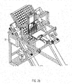
- Fig. 1 is a schematic cross-sectional view of an embodiment of an egg inspection device shown.
- the egg inspection device contains a feed device 1, a lifting device 2, a sampling device 3, a sample receiving device 4, a rinsing device 5 and a control unit 6.
- the lifting device 2 contains an egg stamp 7 and a stop element 8.
- the control unit 6 controls, according to actuators A1, A2, A3, A4, A5, A6, A7 to set or move the aforementioned elements or units.
- the lifting device is a mechanical lifting device with the egg punch 7 and the stop element 8
- a lifting device operated by means of an air flow can also be provided in which the egg is lifted by means of an air flow.
- the egg can be lifted out by means of a stream of air and, for example, pressed against a stop element in order to be brought into the correct position.
- a hose with an opening is positioned under the egg in the tray, and the egg is lifted in the air stream by means of compressed air.
- a guided lifting of the egg is advantageous; this can be done via the egg stamp, preferably rotatably mounted egg stamp, and / or via an air stream.
- the egg is then used by the other Side held in position with a soft suction device, for example.
- This fixation can also take place mechanically and / or by means of an air flow.
- a sliding guidance of the egg position can take place ventrally.
- the feed device 1 has a first actuator A1, the lifting device 2 from the egg punch 7 and the stop element 8 a second actuator A2, which sets the stop element 8, and a third actuator A3, which sets the egg punch 7.
- a first actuator A1 the lifting device 2 from the egg punch 7 and the stop element 8
- a second actuator A2 which sets the stop element 8
- the fourth actuator A4 shown in the figure is drawn up by the syringe 9 shown in this figure.
- a base plate 10 with the syringe 9 attached to it forms a sampling unit, the syringe 9 forming the sampling device.
- the sampling unit as a whole is placed via a fifth actuator A5.
- a sixth actuator A6 is assigned to the sample receiving unit 4 and a seventh actuator is assigned to the flushing device 5.
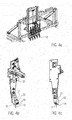
- FIG 2A a supervision of the in Fig. 1 shown egg inspection device, wherein a tray 13 is shown positioned in a starting position.
- a sampling device 9 on the sampling unit, but sampling takes place via cannulas 12 connected to vacuum hoses 11, each cannula with vacuum hose 11 connected to it forming a sampling unit 9, and accordingly five sampling units are provided in the sampling unit. Any number, in particular 5, 10, 15, sampling units 9 can be combined into one unit between one and a multiplicity of sampling units.
- FIG 2A a starting position is shown after the tray 13 has been inserted into the feed device 1 as in the present case, for example half filled with eggs 19.
- the feed device 1 is designed as a type of frame 14 in which the shelf 13 can be inserted in such a way that its side delimiting walls are essentially flush with the frame 14.
- This frame has, on two opposite sides in the transverse direction of the device, a slide 15, which is slidably mounted on corresponding rails 16 and thus by means of the in Figure 2A first actuator A1, not shown, via the control unit 6 from the in Figure 2A starting position shown in an in Figure 2B shown end position can be moved.
- the direction of gravity ie the direction in Fig. 1 , 2A and 2 B from top to bottom as the y-axis
- the axis perpendicular to this vertical ie to the y-axis and transversely to the tray 13 as the z-axis and the axis in which the inclination of the tray 13 extends as the x-axis
- the first actuator A1 ensures a translational movement of the feed device 1 in the yx plane.
- the second actuator A2 and the third actuator A3 ensure a translational movement of the individual elements of the lifting device within the yx plane and perpendicular to the movement of the first actuator A1.
- the fourth or fifth actuator A4, A5 ensures a translational movement of the corresponding elements (sampling device or sampling unit) in the y direction.
- the seventh or eighth actuator A7, A8 ensures a translational movement of the corresponding elements in the x direction.
- the tray 13 is designed as a type of grid 17 with meshes of the same size, with a single egg 18 being able to be held in each mesh. Since the meshes are limited only by strip-like upright walls, each egg 18 lies with its point downward in the respective mesh. That is, in Figure 2A a base side of the eggs 18 is shown.
- the eggs 18 lie in a matrix, in the present example five eggs 18 lying next to one another in the transverse direction (z-axis) and 17 eggs lying one behind the other in the longitudinal direction or oblique direction (x-axis).
- the direction of the z-axis is always referred to as next to one another for the eggs and the translation direction (x-axis) of the feed device 1 is always referred to one behind the other.
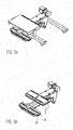
- each sampling device 3 is designed as a module which can be attached to the base plate 10 via screw connections, for example.
- a stop surface 19 is provided, from which the cannula 12 protrudes.
- the cannula 12 is held between the plate elements 21, 22 of the module by means of a type of clamping connection, in that the plate element 22 is fastened by means of the in Figure 4B shown two fastening elements 20, which are Allen screws in the present case, is pressed together.
- a vacuum hose 11 is connected to the rear of each cannula 12, which is preferably a thin metal cannula with a sharp point.
- the vacuum hoses 11 are connected to a pneumatic system not shown in detail in the figures. With the negative pressure generated in the pneumatic system, a predetermined amount of liquid can be removed from the egg 18 after a respective egg has been pierced with the cannula 12.
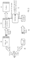
- the egg 18 is positioned.
- the feed device 1 is moved via the control unit 6 in such a way that the first row of eggs, seen in the translation direction of the shelf (x-axis), is level with the sampling device 3 (cf. Figure 2A ) comes to a standstill (step b) in Fig. 3 ).
- the sampling device 3 cf. Figure 2A
- step b) in Fig. 3
- five eggs are arranged under the respective 5 sampling devices 3 of the sampling unit.
- the in Fig. 6 egg stamps 7 shown the five eggs are simultaneously pressed out through the meshes of the tray 13 essentially perpendicular to the tray 13, i.e. perpendicular to the surface formed by the frame 14 of the testicle 13, or perpendicular to the inclined feed plane to be dug out of the horde 13 and against the in Fig. 1 schematically shown stop element 8 pressed.
- the eggs are lifted out of the tray with their thicker back, aligned at an inclined angle between 20 and 80 °.
- the angle ⁇ (compare Fig. 1 ) between the axis of rotation (longitudinal direction) of the egg 18 and the vertical direction (y-axis), ie the direction in which the cannula 12 is pierced into the egg 18 (in the present case the direction in which the sampling unit can be moved in its vertical direction ), due to the trigonometry, corresponds to the angle ⁇ at which the feed device 1 feeds the tray 13 at an angle (cf. Fig. 1 ).
- the angle ⁇ between the axis of rotation (longitudinal direction) of the egg 18 and the cannula 12 corresponds to the angle ⁇ between the x-axis (in the present case the bottom surface) and the direction of translation of the feed device 1, since their legs are perpendicular to one another in pairs.
- the direction in which the eggs are lifted is perpendicular to the plane of the tray, which corresponds to the plane of translation.
- the complete base plate 10 with the sampling devices 3 attached to it i.e. the sampling unit, is moved down on the y-axis so that the five cannulas 12 simultaneously pierce the five eggs 18 lying next to one another.
- the preset target amount of the liquid removed from the egg is shown schematically in Figure 4B shown light barrier 25 detected. That is, as soon as the liquid meniscus in the vacuum hose 11 reaches the light barrier 25, the pressure is kept constant.
- the sampling unit is then withdrawn again (in the vertical direction; y-axis) and the cannulas 12 are withdrawn from the eggs.
- the tips of the cannulas 12 should preferably come to a stop at such a height that the sample receiving device 4 or the rinsing device 5 by means of the device shown in FIG Fig. 1 illustrated sixth and seventh actuator A6, A7, as the arrows in Fig. 1 specify, from the sample dispensing and cleaning group provided with reference numeral 26 can be moved translationally under the cannula tip.
- sample receiving devices 4 i.e. for example cavities
- a matrix of sample receiving devices 4 results.
- step e By means of control by the control unit 6, after translational movement of the titer plate (in the x-axis) under the cannula ends (step e) in Fig. 3 )., the appropriate pressure is now applied to the vacuum hoses 11, so that the amount of liquid removed from the eggs 18 is discharged from the sampling unit devices 3 into the corresponding sample receiving device 27 provided underneath. This takes place essentially simultaneously, so that after five quantities of liquid have been removed from five eggs 18 at the same time in the present example, and again from five liquid samples, one in each case is dispensed into the corresponding sample receiving device.
- the corresponding titer plate (step d) in Fig. 3 ) is previously placed in the egg inspection device by the operator, just like the tray with the eggs.
- estrone sulfate concentration in the allantoic fluid removed from the eggs 18 is determined in order to be able to infer the sex of the embryonic chicks.
- concentration of estrone sulfate concentration in the allantoic fluid removed from the eggs 18 is determined in order to be able to infer the sex of the embryonic chicks.
- One such method for the biological determination of the estrone sulfate concentration for identifying female and male chicken embryos is described in the German patent application application number 10 2015 226 490.4 described. Based a colorimetric measurement can indirectly determine the concentration of estrone sulfate.
- the five eggs 18 held by the lifting device are placed back into the position of the tray (step c) in FIG Fig. 3 ). Alternatively, this can also take place immediately after the liquid has been taken and before the sample is dispensed.
- the titer plate ie the matrix of sample receiving devices 4, is returned to their in Figure 2B or 1 basic position shown in the sample dispensing and cleaning assembly moved.
- the rinsing device 5 which in the present example consists of a tub 28 which is filled with alcohol and a collecting vessel 29, is now operated by means of the seventh actuator A7 (cf. Fig. 1 ), as in Fig. 7 shown moved from the basic position within the sample dispensing and cleaning assembly into a rinsing position, not shown in the figure, in which the rinsing device 7 comes to a stand essentially below the cannulas 12, ie below the respective sampling device 3.
- the cannulas can be cleaned after each lancing process (step f) in Fig. 3 ).
- the sampling unit is moved vertically downwards, i.e. on the y-axis, in order to immerse the cannulas 12 with their tips in the tub 28 with alcohol.
- a little alcohol is now sucked from the tub 28 into the cannula via the control unit 6 in order to denature the biological residues.
- the sampling unit is then withdrawn upwards in the vertical direction (along the y-axis) via the fifth actuator A5 and the collecting vessel 29 is moved from the rinsing position into a rinsing liquid dispensing position, so that the collecting vessel 29 is arranged under the sampling device 3.
- Demineralized water which is stored in a container of the device (not shown in the figures), is then introduced into the cannulas 12 via the vacuum hoses and the cannulas 12 are rinsed with this water, which is collected in the collecting vessel 29.
- the cannulas and / or the vacuum tubes are preferably dried. This can be done, for example, by means of separate air nozzles which are provided in the examination device and which inflate the cannulas 12 from the outside. In the present Exemplary embodiment, air is blown through the vacuum hoses 11 and thus the cannulas 12 by means of the pneumatic system.
- the flushing device 5 is again in the basic position, as shown in FIG Fig. 1 is shown withdrawn.
- the feed device 1 is set via the control unit 6 in such a way that the tray 13 is displaced obliquely forward one row at a time in the translation direction in order to sample the next row of five eggs 18 at the same time.
- the position in the matrix of sample receiving devices 4 in which the amount of liquid removed is placed on the titer plate corresponds to the position of the eggs in the trays. In this way, a single sample receiving device can be clearly assigned to each egg in the testicle.
- the entire egg inspection device can be operated via a touch-sensitive computer screen which is connected to the control unit 6.
- the computer screen is in the Figure 2A and B. provided with reference number 30.
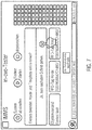
- FIG Fig. 7 An example of a user interface of the software by means of which the device which is displayed on the computer screen 30 is controlled is shown in FIG Fig. 7 shown.
- Fig. 7 a state of the user interface is shown in which the sampling procedure has been carried out once to the end. Therefore, in the schematic arrangement of the eggs in the hordes shown on the right, the squares are filled in.
- each tray and the corresponding titer plate into which the samples are dispensed can be clearly assigned to one another. In the present example, this is ensured by means of an RFID tag, which is provided on a testicle and on the titer plate. A tray number stored in the RFID tag can be assigned a titer plate number accordingly.
- the characterization is usually not carried out within the device according to the invention but in a separate one Contraption.
- the titer plates filled with samples are removed from the device and fed to a corresponding device to determine the estrone sulfate concentration. Because the arrangement of the eggs in trays is known and the position in which sample receiving device the corresponding liquid is dispensed from a respective egg of the tray, it can also be determined later which egg in the tray corresponds to which result on the titer plate.
- the egg size can also vary depending on the age of the laying hens, it is often difficult to sample all eggs with the same cannula length (protrusion of the cannula from the stop surface 19). This is because the protruding cannula length determines the depth from which the corresponding amount of liquid is removed from the egg 18. For example, in order to remove allantoic fluid, a predetermined depth must always be reached at a previously described angle.
- the protruding length of the cannula can be adjusted by means of the control unit.
- the control unit can adjust and vary the length of the cannula from the control unit depending on information about the respective egg, and thus selectively specify a depth for each corresponding egg depending on its properties, such as its thickness, from which the amount of liquid is taken becomes.
- control unit can move the sampling device forward until the cannula is immersed in the liquid in the egg (allantois).
- the control unit can, for example, detect the immersion of the cannula in a liquid (allantois) and stop the forward movement of the sampling unit when the desired depth is reached. Then, for example, the suction process is started.
- the length adjustment of the cannulas can also constitute an invention in itself independently of the egg examination device.
- FIGs 5A and 5B A detailed view of the sample delivery and cleaning assembly 26 is shown. This has a cover 35 for protection against environmental influences such as dust, a first storage surface 36 on which the flushing device 5 rests, and a second storage surface 37 on which the sample receiving devices 4 combined in the titer plate are positioned. As in Figure 5B shown, two titer plates are provided here. Instead of the titer plate, a fleece can also be provided in which the sample taken is released at various points.
- Each of the two storage areas are each attached to a translationally movable arm.
- the two arms can move via the seventh actuator A7, the rinsing device 5 or the titer plate / fleece independently of one another from the basic position into the corresponding dispensing position for the sample receiving unit or for rinsing or blow-out position for the rinsing unit.
- the cleaning assembly 26 can also form an invention in itself independently of the egg inspection device.
- the egg stamps 24 are designed as slightly conical plastic sleeves 39, which have an element 38 made of regulating and compensating material, for example compressible material, in their center.
- the egg stamps 24 are driven by the pistons attached to the underside of the in Fig. 1 third actuator A3 shown moved translationally.
- the tip of the eggs is brought into contact with the element 38 made of regulating and compensating material and the eggs are supported by the conical plastic sleeves 39, which are designed as suction cups comprising egg heads, in their circumferential direction.
- each egg 18 it is advantageous, for example, to determine the size and shape of each egg 18 by means of an observation device, such as a camera, in order to obtain information about the properties or position of each egg by means of image processing methods.
- This information can be passed on to the control device 6, which then adjusts the length accordingly for the respective cannula 12 of the respective sampling unit 3 via the actuators of the sampling devices.
- a connection with a camera and light source for aligning the egg is conceivable.
- samples are taken from five eggs at the same time.
- Sampling is not limited to five eggs. A single one is sufficient for the present invention Sampling unit off. Preferably, however, at least two, in particular up to ten eggs can be sampled at the same time.
- a simple syringe can alternatively be provided, as in the first exemplary embodiment, which can be actuated via a mechanical piston.
- the egg examination device it is particularly effectively possible to pierce the eggs in an automated manner at an oblique angle, whereby preferably the sampling device, ie the cannula arranged on it, is pierced in a vertical direction, ie in the direction of gravity, with each egg individually is slightly inclined at an angle of 20 ° to 80 °.
- the eggs stored in the trays together with the tray are fed in at an angle to the direction of gravity via the feed device and then lifted out of the respective mesh of the tray by means of the lifting device perpendicular to this inclined surface.
- the eggs are held in the lifting device, in the present case by means of plastic sleeves 39, which are formed as suction cups comprising egg heads, and the stop element individually at the side, front and back and independently of the tray, in order to ensure selective, precise piercing at a predefined angle and eggs to be sampled ..
- the angle at which the feed device 1 feeds the eggs essentially corresponds to the inclined position of the eggs in relation to the cannula 12.
- angle ranges are between 30 ° and 60 °, preferably between 40 ° and 50 °, in particular 45 °.
- the allantoic fluid collects to a suitable extent at a well-defined location in the egg, so that a well-defined amount of allantoic fluid can be removed by means of the cannula.
- the tip of the cannula used has at least two openings. It has been found that if only one opening is used, ideal sampling is not possible under all conditions is achieved. More than two openings in the cannula are also possible. In some circumstances a single opening in the cannula may also be advantageous.
- a UV lamp unit 41 (cf. Fig. 1 ) can be provided so that UV light is emitted by this UV lamp unit 41 onto the region where the eggs are sampled.
- a UV tube for example, can be used which extends along the z-axis, i.e. along the direction of the eggs lying next to one another.
- placing the UV lamp unit 41 between the sampling unit 3 and the sample dispensing and cleaning assembly 26 is advantageous.
- the inclination with which the feed device 1 feeds the tray can also be changed selectively as a function of egg characteristics.
- the settings of the entire device can take place via the control unit 6.
- this image information can be processed in order to selectively determine the positioning of the individual eggs for removing the amount of liquid, and / or depending on the egg thickness, the egg size, and / or determine the cannula length.
- the vacuum hoses can be designed in such a way that their pressure can be set variably and independently of one another.
- the individual sampling devices being attached to a base plate, it can also be advantageous that the individual sampling devices can be moved relative to one another.
Claims (18)
- Dispositif d'examen des œufs avec,
un dispositif de prélèvement d'échantillon (3) au moyen duquel il est possible de prélever un échantillon de fluide à prélever sur un œuf (18) respectif provenant d'une claie (13) garnie d'œufs,
un dispositif d'acheminement (1) permettant d'acheminer la claie (13) garnie d'œufs jusqu'au dispositif de prélèvement d'échantillon (3),
et une unité de commande (6) au moyen de laquelle le dispositif d'acheminement (1) et le dispositif de prélèvement d'échantillon (3) peuvent être commandés, caractérisé en ce que
le dispositif d'acheminement (1) est réalisé de manière à acheminer la claie (13) jusqu'au dispositif de prélèvement d'échantillon (3) selon un angle oblique compris entre 20° et 80° par rapport à un plan perpendiculaire à la direction de la pesanteur, et le dispositif d'examen des œufs comporte en outre un dispositif de retrait (2) au moyen duquel il est possible de retirer l'œuf (18) de la claie (13) et au moyen duquel il est possible de placer l'œuf (18) dans une position de prélèvement d'échantillon dans laquelle il peut être percé par le dispositif de prélèvement d'échantillon (3) de manière oblique par rapport à son axe de rotation et la quantité de fluide à prélever peut être prélevée sur l'œuf (18) au moyen du dispositif de prélèvement d'échantillon (3), dans lequel le dispositif de retrait (2) peut être commandé au moyen de l'unité de commande (6). - Dispositif d'examen des œufs selon la revendication 1, caractérisé en ce que le dispositif de retrait est configuré de telle manière qu'il peut faire tourner un œuf qu'il a retiré afin de le placer dans une position de perçage prédéterminée.
- Dispositif d'examen des œufs selon la revendication 1 ou 2, caractérisé en ce que le dispositif de retrait est un dispositif de retrait mécanique, ou un dispositif de retrait actionné au moyen d'un flux d'air et au sein duquel l'œuf est retiré au moyen d'un flux d'air.
- Dispositif d'examen des œufs selon l'une quelconque des revendications précédentes, caractérisé en ce que le dispositif de prélèvement d'échantillon (3) présente une canule (12) reliée à un dispositif générateur de vide, dans lequel la quantité de fluide à prélever dans l'œuf (18) peut être commandée au moyen de l'unité de commande (6) par l'intermédiaire de la pression générée dans le dispositif générateur de vide, et le dispositif de prélèvement d'échantillon (3) présente en particulier une barrière photoélectrique (25) par l'intermédiaire de laquelle l'unité de commande (6) peut déterminer si la quantité de fluide retirée de l'œuf (18) correspond à la quantité de fluide à prélever.
- Dispositif d'examen des œufs selon l'une quelconque des revendications précédentes, caractérisé en ce que le dispositif de prélèvement d'échantillon (3) présente une tourelle à canules muni de plusieurs canules.
- Dispositif d'examen des œufs selon la revendication 4, caractérisé en ce que la canule (12) comprend au moins deux ouvertures au moyen desquelles la quantité de fluide à prélever peut être prélevée sur l'œuf (18).
- Dispositif d'examen des œufs selon l'une quelconque des revendications 4 à 6, caractérisé en ce qu'une longueur de saillie de la canule (12), avec laquelle celle-ci dépasse d'une surface de butée (19) prévue au niveau du dispositif de prélèvement d'échantillon (3) et venant en contact avec l'œuf (18) lors du prélèvement d'échantillon, peut être ajustée, et la longueur de saillie de la canule (12) peut en particulier être ajustée au moyen de l'unité de commande (6).
- Dispositif d'examen des œufs selon l'une quelconque des revendications précédentes, caractérisé en ce que le dispositif d'examen des œufs comprend au moins deux dispositifs de prélèvement d'échantillon (3), combinés en une unité de prélèvement d'échantillon de sorte que l'échantillon de fluide à prélever peut être prélevé sur respectivement un œuf de la claie (13) de manière simultanée grâce à chaque dispositif de prélèvement d'échantillon (3) parmi les au moins deux dispositifs de prélèvement d'échantillon (3), et en ce que au moins deux dispositifs de retrait (2) sont prévus, dans lequel l'œuf de la claie (13) associé à l'unité de prélèvement d'échantillon (3) respective peut être retiré de la claie au moyen du dispositif de retrait (2) respectif parmi les au moins deux dispositifs de retrait (2) et être placé dans la position de prélèvement d'échantillon.
- Dispositif d'examen des œufs selon l'une quelconque des revendications précédentes, caractérisé en ce que l'unité de commande (6) est réalisée de telle manière qu'elle ajuste la quantité de fluide à prélever sur l'œuf de manière individuelle pour chacun des au moins deux dispositifs de prélèvement d'échantillon (3) en fonction de paramètres d'œuf de l'œuf (18) respectivement associé au dispositif de prélèvement d'échantillon (3).
- Dispositif d'examen des œufs selon l'une quelconque des revendications précédentes, caractérisé en ce que le dispositif de prélèvement d'échantillon (3) peut être déplacé dans le sens de la pesanteur ; et parallèlement à la surface au sein de laquelle la claie (13) peut être déplacée en translation grâce au dispositif d'acheminement, et peut être déplacé dans une direction transversale par rapport à la direction de translation de la claie (13) imposée par le dispositif d'acheminement, et le dispositif d'examen des œufs comprend en particulier un dispositif de réception d'échantillon (4) conçu pour recevoir la quantité de fluide fournie par le dispositif de prélèvement d'échantillon (3) et prélevée sur l'œuf (18) par le dispositif de prélèvement d'échantillon (3).
- Dispositif d'examen des œufs selon la revendication 8, caractérisé en ce que ; le dispositif d'examen des œufs comprend au moins deux dispositifs de réception d'échantillon (4), combinés en une unité, à partir desquels la quantité de fluide respective prélevée sur l'œuf (18) respectif par les au moins deux dispositifs de prélèvement d'échantillon (3) peut être fournie, et les au moins deux dispositifs de réception d'échantillon (4) combinés en une unité sont en particulier réalisés sous forme de nappe ou plaque de titrage.
- Dispositif d'examen des œufs selon l'une quelconque des revendications précédentes, caractérisé en ce que le dispositif de prélèvement d'échantillon (3) peut être positionné dans une position de fourniture après prélèvement d'échantillon sur l'œuf (18) respectif et extraction de celui-ci, et dans lequel le dispositif de réception d'échantillon (4), lorsque le dispositif de prélèvement d'échantillon (3) est positionné dans la position de fourniture, peut être déplacé d'une position de repos de dispositif de réception d'échantillon jusqu'à une position de réception dans laquelle l'échantillon peut être fourni dans le dispositif de réception d'échantillon (4) par le dispositif de prélèvement d'échantillon (3).
- Dispositif d'examen des œufs selon l'une quelconque des revendications précédentes, caractérisé en ce que le dispositif d'examen des œufs comprend un dispositif de rinçage (5) qui, après la fourniture d'échantillon dans le dispositif de réception d'échantillon (4), peut être déplacé d'une position de repos de dispositif de rinçage jusqu'à une position de rinçage dans laquelle le dispositif de prélèvement d'échantillon (3) est rincé au moyen d'un profil de pression de la pression générée dans le dispositif générateur de vide, et en particulier le dispositif de réception d'échantillon (4) et le dispositif de rinçage (5) permettant de rincer le dispositif de prélèvement d'échantillon sont réalisés en une unité.
- Dispositif d'examen des œufs selon l'une quelconque des revendications précédentes, caractérisé en ce que le dispositif de retrait (2) présente un piston à œuf auquel il est possible de faire traverser une maille de la claie afin de retirer l'œuf (18) placé dans ladite maille, et un élément de butée (8), contre lequel l'œuf (18) peut être pressé par le piston à œuf (7) et qui détermine la position de prélèvement d'échantillon, est prévu, et en particulier respectivement au moins un actionneur pouvant être commandé par l'intermédiaire de l'unité de commande (6) est associé au piston à œuf (7) et à l'élément de butée (8).
- Dispositif d'examen des œufs selon l'une quelconque des revendications précédentes, caractérisé en ce que le dispositif d'examen des œufs comprend un dispositif de détermination de position par l'intermédiaire duquel la situation de l'œuf (18) peut être déterminée, dans lequel l'unité de commande (6) commande un positionnement de l'œuf (18) sur la base des données du dispositif de détermination de position.
- Dispositif d'examen des œufs selon l'une quelconque des revendications précédentes, caractérisé en ce que le dispositif d'examen des œufs comprend une unité d'éclairage permettant de mirer l'œuf afin de mettre en œuvre une détermination de position et/ou une correction de l'œuf (18), et le piston à œuf (7) est en particulier muni de l'unité d'éclairage.
- Dispositif d'examen des œufs selon l'une quelconque des revendications précédentes, caractérisé en ce que le dispositif d'examen des œufs comprend une unité de lampe UV (41) au moyen de laquelle au moins un des dispositifs ci-dessous est éclairé afin de tuer les bactéries et/ou les germes: œuf (18), dispositif de prélèvement d'échantillon (3), dispositif de rinçage (5), dispositif de réception d'échantillon (4), dispositif de retrait (2).
- Dispositif d'examen des œufs selon l'une quelconque des revendications précédentes, caractérisé en ce que l'unité de commande (6) est réalisée de telle manière qu'un échantillonnage des œufs de la claie (13) a lieu de manière automatisée après introduction de la claie (13) garnie avec les œufs (18) dans le dispositif d'examen des œufs, et des informations appropriées sont fournies après que tous les œufs (18) de la claie ont été échantillonnés.
Priority Applications (2)
| Application Number | Priority Date | Filing Date | Title |
|---|---|---|---|
| EP20171704.8A EP3705889A1 (fr) | 2016-08-12 | 2017-08-04 | Dispositif d'examen d' ufs |
| PL17749176T PL3497441T3 (pl) | 2016-08-12 | 2017-08-04 | Urządzenie do badania jaj |
Applications Claiming Priority (2)
| Application Number | Priority Date | Filing Date | Title |
|---|---|---|---|
| DE102016215127.4A DE102016215127A1 (de) | 2016-08-12 | 2016-08-12 | Eieruntersuchungseinrichtung |
| PCT/EP2017/069769 WO2018029096A1 (fr) | 2016-08-12 | 2017-08-04 | Dispositif pour examiner les œufs |
Related Child Applications (2)
| Application Number | Title | Priority Date | Filing Date |
|---|---|---|---|
| EP20171704.8A Division-Into EP3705889A1 (fr) | 2016-08-12 | 2017-08-04 | Dispositif d'examen d' ufs |
| EP20171704.8A Division EP3705889A1 (fr) | 2016-08-12 | 2017-08-04 | Dispositif d'examen d' ufs |
Publications (2)
| Publication Number | Publication Date |
|---|---|
| EP3497441A1 EP3497441A1 (fr) | 2019-06-19 |
| EP3497441B1 true EP3497441B1 (fr) | 2021-03-03 |
Family
ID=59558405
Family Applications (2)
| Application Number | Title | Priority Date | Filing Date |
|---|---|---|---|
| EP17749176.8A Active EP3497441B1 (fr) | 2016-08-12 | 2017-08-04 | Dispositif pour examiner les oeufs |
| EP20171704.8A Pending EP3705889A1 (fr) | 2016-08-12 | 2017-08-04 | Dispositif d'examen d' ufs |
Family Applications After (1)
| Application Number | Title | Priority Date | Filing Date |
|---|---|---|---|
| EP20171704.8A Pending EP3705889A1 (fr) | 2016-08-12 | 2017-08-04 | Dispositif d'examen d' ufs |
Country Status (12)
| Country | Link |
|---|---|
| US (2) | US11576355B2 (fr) |
| EP (2) | EP3497441B1 (fr) |
| CN (2) | CN109844523B (fr) |
| AU (2) | AU2017311519B2 (fr) |
| BR (2) | BR122020014386B1 (fr) |
| CA (2) | CA3085580C (fr) |
| DE (1) | DE102016215127A1 (fr) |
| ES (1) | ES2868698T3 (fr) |
| PL (1) | PL3497441T3 (fr) |
| RU (2) | RU2749488C1 (fr) |
| UA (2) | UA126800C2 (fr) |
| WO (1) | WO2018029096A1 (fr) |
Families Citing this family (8)
| Publication number | Priority date | Publication date | Assignee | Title |
|---|---|---|---|---|
| EP3648584A1 (fr) | 2017-07-06 | 2020-05-13 | Seleggt GmbH | Procédé de production de poulet faisant appel au sexage d'embryons de poulet |
| US20200359606A1 (en) * | 2018-02-07 | 2020-11-19 | Seleggt Gmbh | Method for sampling an egg |
| NL2021022B1 (en) * | 2018-05-30 | 2019-12-10 | Seleggt Gmbh | Method for determining the gender of a chicken embryo |
| NL2024699B1 (en) * | 2020-01-17 | 2021-10-13 | In Ovo Holding B V | Egg Characteristic Determining Device |
| NL2024700B1 (en) | 2020-01-17 | 2021-09-08 | In Ovo Holding B V | Egg Sampling Device |
| NL2024701B1 (en) | 2020-01-17 | 2021-09-08 | In Ovo Holding B V | Egg Positioning Device |
| CN113848291B (zh) * | 2021-12-01 | 2022-03-18 | 江苏中农生物科技有限公司 | 蛋制品安全采样快速检测系统及方法 |
| CN116806733B (zh) * | 2023-08-23 | 2023-10-27 | 广东省农业科学院动物科学研究所 | 一种咸鸭蛋生产用自动分拣设备 |
Family Cites Families (42)
| Publication number | Priority date | Publication date | Assignee | Title |
|---|---|---|---|---|
| US1472674A (en) * | 1922-01-03 | 1923-10-30 | Walter G Reagan | Combined egg candling and assembling device |
| US2186196A (en) * | 1934-08-31 | 1940-01-09 | Kraft Phenix Cheese Corp | Egg candling machine |
| US2835386A (en) * | 1953-11-12 | 1958-05-20 | Marzolf Mfg Company | Egg grader |
| AT328300B (de) * | 1973-07-24 | 1976-03-10 | Goldhofer Fahrzeugwerk Kg | Fahrzeug mit einer zugmaschine und einem anhanger |
| DE3326520A1 (de) | 1983-07-22 | 1985-01-31 | Hubert Prof. Dr. 2000 Hamburg Köster | Verfahren zur definierten verknuepfung doppelhelikaler dna-fragmente mittels einer linker-dna sowie als linker-dna geeignete oligonucletide |
| JPS6033050A (ja) * | 1983-08-04 | 1985-02-20 | Kazuhiro Kaneko | 検卵器 |
| EP0625007A4 (en) | 1992-01-27 | 1997-02-26 | Univ North Carolina State | Gene transfer in birds by introduction of dna into muscle in ovo. |
| US5460083A (en) * | 1994-01-14 | 1995-10-24 | Seymour, Inc. | Egg washer, breaker and separator system |
| US5898488A (en) * | 1997-01-21 | 1999-04-27 | Kuhl; Jeffrey B. | Method and apparatus for candling eggs and filling trays with fertile eggs |
| US6176199B1 (en) * | 1998-10-20 | 2001-01-23 | Embrex, Inc. | Method for localizing allantoic fluid of avian eggs |
| US6244214B1 (en) * | 1999-01-06 | 2001-06-12 | Embrex, Inc. | Concurrent in ovo injection and detection method and apparatus |
| RU2161404C1 (ru) * | 1999-07-19 | 2001-01-10 | Западно-Сибирская зональная опытная станция по птицеводству | Способ определения оплодотворенности яиц птицы |
| US7041439B2 (en) * | 2001-04-17 | 2006-05-09 | Embrex, Inc. | Methods and apparatus for selectively processing eggs having identified characteristics |
| US6527498B2 (en) * | 2001-04-17 | 2003-03-04 | Embrex, Inc. | Apparatus and method for reorienting an egg between vertical and horizontal orientations |
| ITSV20010012A1 (it) | 2001-04-20 | 2002-10-20 | Irritec Srl | Emettitore autocompensante per irrigazione goccia a goccia |
| US6591124B2 (en) * | 2001-05-11 | 2003-07-08 | The Procter & Gamble Company | Portable interstitial fluid monitoring system |
| US7617795B2 (en) * | 2004-10-13 | 2009-11-17 | Embrex, Inc. | Methods and apparatus for injecting and sampling material through avian egg membranes |
| BRPI0616255A2 (pt) * | 2005-09-20 | 2011-06-14 | Embrex Inc | mÉtodos de localizar um blastoderme dentro de um ovo de ave e de determinar se um ovo de ave É fÉrtil |
| FR2895085B1 (fr) | 2005-12-21 | 2008-07-04 | Breuil Sa Engineering Const Et | Dispositf de mirage d'oeufs. |
| ES2668637T3 (es) * | 2005-12-23 | 2018-05-21 | Visio Nerf | Procedimiento e instalación de miraje de los huevos |
| NL1031823C2 (nl) * | 2006-05-16 | 2007-11-20 | Staalkat Internat B V | Detectie van open breuken in eieren. |
| US8107060B2 (en) * | 2007-10-05 | 2012-01-31 | Embrex, Inc. | Methods and apparatus for candling eggs via embryo heartbeat detection |
| JP5226435B2 (ja) * | 2008-08-29 | 2013-07-03 | 株式会社堀場製作所 | 排ガス測定装置および排ガス測定方法 |
| CN101409034B (zh) * | 2008-10-30 | 2010-12-22 | 常熟华东汽车有限公司 | 展示车的液晶显示屏架升降机构 |
| US8245632B1 (en) * | 2010-03-20 | 2012-08-21 | Terry Fields | Egg boiling device |
| WO2011119825A2 (fr) * | 2010-03-24 | 2011-09-29 | Fps Food Processing Systems, B.V. | Système évolué permettant de casser des œufs |
| BE1019291A3 (nl) * | 2010-04-15 | 2012-05-08 | Innovatec B V | Inrichting voor het schouwen en overleggen van eieren en een werkwijze daarbij toegepast. |
| RU2449780C1 (ru) | 2010-10-18 | 2012-05-10 | Учреждение Российской академии наук Институт биомедицинских исследований Владикавказского научного центра РАН и правительства РСО-Алания (УРАН ИБМИ ВНЦ) | Способ воздействия антимутагенного средства на организм |
| US20130283894A1 (en) * | 2010-11-05 | 2013-10-31 | Moba Group B.V. | Method and Apparatus for Examining Eggs |
| GB201102495D0 (en) * | 2011-02-13 | 2011-03-30 | Innovo Mimetics Ltd | Automated biological sample collection system and method |
| US9131666B2 (en) * | 2012-05-18 | 2015-09-15 | Yamamoto Corp. | Hatching egg inspection apparatus |
| CN203194488U (zh) * | 2013-02-20 | 2013-09-18 | 福州闽台机械有限公司 | 刺杆自重式蛋壳刺孔机 |
| PL3057414T3 (pl) * | 2013-10-17 | 2023-10-23 | Boehringer Ingelheim Animal Health USA Inc. | Urządzenie do selektywnego namierzania struktur zarodkowych i dostarczania substancji |
| CN203542821U (zh) * | 2013-11-29 | 2014-04-16 | 刘运武 | 切坯机借力驱动装置 |
| EP3146329A1 (fr) * | 2014-05-22 | 2017-03-29 | Zoetis Services LLC | Procédés et appareil pour traiter des ufs de manière sélective selon le sexe et d'autres caractéristiques |
| FR3023617B1 (fr) * | 2014-07-11 | 2018-06-15 | Tronico | Dispositif non invasif de determination de la fertilite et/ou du sexe d’un oeuf, et procede correspondant. |
| US20160022095A1 (en) * | 2014-07-28 | 2016-01-28 | Wei Yang | Electric egg beater |
| US10369045B2 (en) * | 2014-07-29 | 2019-08-06 | The Johns Hopkins University | Micromanipulation systems and methods |
| CN204638316U (zh) * | 2015-04-30 | 2015-09-16 | 常州德海精密轴承有限公司 | 配有提升机装置的气流涡旋磨粉机 |
| DE102015226490A1 (de) | 2015-12-22 | 2017-06-22 | Universität Leipzig | Verfahren zur in ovo Geschlechterbestimmung von Küken |
| DE102018105512A1 (de) * | 2018-03-09 | 2019-09-12 | Technische Universitaet Dresden | Verfahren zur in-ovo fertilisations- und geschlechtsbestimmung am geschlossenen ei |
| CN109335075B (zh) * | 2018-11-22 | 2024-03-22 | 安徽田园居电子商务股份有限公司 | 一种邮递用禽蛋包装机 |
-
2016
- 2016-08-12 DE DE102016215127.4A patent/DE102016215127A1/de active Pending
-
2017
- 2017-08-04 BR BR122020014386-0A patent/BR122020014386B1/pt active IP Right Grant
- 2017-08-04 CN CN201780063103.4A patent/CN109844523B/zh active Active
- 2017-08-04 ES ES17749176T patent/ES2868698T3/es active Active
- 2017-08-04 RU RU2020122775A patent/RU2749488C1/ru active
- 2017-08-04 BR BR112019002618-5A patent/BR112019002618B1/pt active IP Right Grant
- 2017-08-04 CN CN202010737144.0A patent/CN112014533A/zh active Pending
- 2017-08-04 CA CA3085580A patent/CA3085580C/fr active Active
- 2017-08-04 UA UAA201902316A patent/UA126800C2/uk unknown
- 2017-08-04 US US16/324,838 patent/US11576355B2/en active Active
- 2017-08-04 EP EP17749176.8A patent/EP3497441B1/fr active Active
- 2017-08-04 UA UAA202004809A patent/UA126825C2/uk unknown
- 2017-08-04 PL PL17749176T patent/PL3497441T3/pl unknown
- 2017-08-04 EP EP20171704.8A patent/EP3705889A1/fr active Pending
- 2017-08-04 AU AU2017311519A patent/AU2017311519B2/en active Active
- 2017-08-04 RU RU2019103924A patent/RU2727743C1/ru active
- 2017-08-04 WO PCT/EP2017/069769 patent/WO2018029096A1/fr active Application Filing
- 2017-08-04 CA CA3033318A patent/CA3033318C/fr active Active
-
2020
- 2020-07-22 AU AU2020207812A patent/AU2020207812B2/en active Active
- 2020-08-19 US US16/997,675 patent/US11596130B2/en active Active
Non-Patent Citations (1)
| Title |
|---|
| None * |
Also Published As
| Publication number | Publication date |
|---|---|
| BR122020014386B1 (pt) | 2022-10-11 |
| BR112019002618A2 (pt) | 2019-05-28 |
| CN112014533A (zh) | 2020-12-01 |
| AU2020207812A1 (en) | 2020-08-06 |
| AU2017311519A1 (en) | 2019-03-07 |
| US20190166805A1 (en) | 2019-06-06 |
| US11576355B2 (en) | 2023-02-14 |
| DE102016215127A1 (de) | 2018-02-15 |
| UA126825C2 (uk) | 2023-02-08 |
| UA126800C2 (uk) | 2023-02-08 |
| CN109844523B (zh) | 2022-05-17 |
| RU2727743C1 (ru) | 2020-07-23 |
| US11596130B2 (en) | 2023-03-07 |
| US20200375153A1 (en) | 2020-12-03 |
| EP3497441A1 (fr) | 2019-06-19 |
| CA3033318C (fr) | 2021-06-08 |
| BR112019002618B1 (pt) | 2022-09-27 |
| CA3085580C (fr) | 2022-04-19 |
| RU2749488C1 (ru) | 2021-06-11 |
| CA3033318A1 (fr) | 2018-02-15 |
| PL3497441T3 (pl) | 2021-09-13 |
| AU2017311519B2 (en) | 2020-08-20 |
| AU2020207812B2 (en) | 2021-03-18 |
| EP3705889A1 (fr) | 2020-09-09 |
| CA3085580A1 (fr) | 2018-02-15 |
| WO2018029096A1 (fr) | 2018-02-15 |
| CN109844523A (zh) | 2019-06-04 |
| ES2868698T3 (es) | 2021-10-21 |
Similar Documents
| Publication | Publication Date | Title |
|---|---|---|
| EP3497441B1 (fr) | Dispositif pour examiner les oeufs | |
| DE60300734T2 (de) | Anordnungen zur Vorbehandlung von Proben | |
| DE4212821C2 (de) | Vorrichtung zum Entfernen eines Verschlusses von der Öffnung eines Behälters und zur Entnahme von flüssigen Inhalten | |
| DE2633085C3 (de) | Vorrichtung zum automatischen Züchten lebender Gewebe oder Zellen | |
| EP1019718B1 (fr) | Dispositif et procede pour examiner des cellules a l'aide de la methode patch-clamp | |
| EP2203776B1 (fr) | Procédés pour positionner des échantillons biologiques dans un dispositif à microscope et appareils pour effectuer ces procédés | |
| EP0278374A2 (fr) | Dispositif de détermination de la libération de composants actifs par des produits pharmaceutiques | |
| DE19918442A1 (de) | Färbeautomat zum Einfärben von Objekten zur mikroskopischen Untersuchung | |
| DE3237999A1 (de) | Probenzufuehrvorrichtung fuer luftdicht verschlossene probenbehaelter | |
| WO2007134814A1 (fr) | Dispositif et procédé de production automatisée reproductible d'échantillons cellulaires ou tissulaires à analyser placés sur des porte-objets | |
| EP1539922B1 (fr) | Procede de mise en culture de cellules, notamment de cellules humaines ou animales | |
| DE202011110050U1 (de) | Vorrichtung zur automatischen Erfassung von Substanzen für Analysen | |
| WO2018077352A1 (fr) | Dispositif et procédé de traitement d'échantillons contenant des cellules biologiques | |
| EP1539921B1 (fr) | Dispositif de mise en culture de cellules, notamment de cellules humaines ou animales | |
| WO2008055612A1 (fr) | Dispositifs et procédés pour analyses électrophysiologiques de cellules | |
| DE2702157A1 (de) | Verfahren und vorrichtung zum ausblasen von eiern | |
| DE102014015418B3 (de) | Mikrosystem und Verfahren zur Manipulation von biologischem Material | |
| WO2008155128A2 (fr) | Procédé et dispositif de positionnement et, éventuellement, d'orientation d'un objet | |
| DE3044015C2 (de) | Verfahren und Einrichtung zur Präparation von in Teilung vorliegenden Zellen für die Chromosomenanalyse | |
| WO2013064237A2 (fr) | Détermination automatique de structures | |
| EP3136994A1 (fr) | Dispositif, système et procédé pour l'application et l'introduction d'au moins une solution de test d'allergène sur et dans la peau d'une partie du corps d'un individu à tester | |
| EP2977740A1 (fr) | Dispositif et procédé pour l'échantillonnage automatique de fibres singulaire d'un réservoire des fibres et pour transférer d'une fibre singulaire à un appareil subséquent | |
| WO2012155973A1 (fr) | Procédé et dispositif pour la détermination automatique de la position d'un microsystème pour la manipulation d'un micro-objet sphérique | |
| EP2773994A2 (fr) | Détermination automatique de structures |
Legal Events
| Date | Code | Title | Description |
|---|---|---|---|
| STAA | Information on the status of an ep patent application or granted ep patent |
Free format text: STATUS: UNKNOWN |
|
| STAA | Information on the status of an ep patent application or granted ep patent |
Free format text: STATUS: THE INTERNATIONAL PUBLICATION HAS BEEN MADE |
|
| PUAI | Public reference made under article 153(3) epc to a published international application that has entered the european phase |
Free format text: ORIGINAL CODE: 0009012 |
|
| STAA | Information on the status of an ep patent application or granted ep patent |
Free format text: STATUS: REQUEST FOR EXAMINATION WAS MADE |
|
| 17P | Request for examination filed |
Effective date: 20190228 |
|
| AK | Designated contracting states |
Kind code of ref document: A1 Designated state(s): AL AT BE BG CH CY CZ DE DK EE ES FI FR GB GR HR HU IE IS IT LI LT LU LV MC MK MT NL NO PL PT RO RS SE SI SK SM TR |
|
| AX | Request for extension of the european patent |
Extension state: BA ME |
|
| DAV | Request for validation of the european patent (deleted) | ||
| DAX | Request for extension of the european patent (deleted) | ||
| RAP1 | Party data changed (applicant data changed or rights of an application transferred) |
Owner name: SELEGGT GMBH |
|
| RIC1 | Information provided on ipc code assigned before grant |
Ipc: A01K 43/00 20060101ALI20200714BHEP Ipc: A01K 45/00 20060101ALI20200714BHEP Ipc: G01N 33/08 20060101AFI20200714BHEP |
|
| GRAP | Despatch of communication of intention to grant a patent |
Free format text: ORIGINAL CODE: EPIDOSNIGR1 |
|
| STAA | Information on the status of an ep patent application or granted ep patent |
Free format text: STATUS: GRANT OF PATENT IS INTENDED |
|
| INTG | Intention to grant announced |
Effective date: 20200924 |
|
| GRAS | Grant fee paid |
Free format text: ORIGINAL CODE: EPIDOSNIGR3 |
|
| STAA | Information on the status of an ep patent application or granted ep patent |
Free format text: STATUS: GRANT OF PATENT IS INTENDED |
|
| GRAA | (expected) grant |
Free format text: ORIGINAL CODE: 0009210 |
|
| STAA | Information on the status of an ep patent application or granted ep patent |
Free format text: STATUS: THE PATENT HAS BEEN GRANTED |
|
| AK | Designated contracting states |
Kind code of ref document: B1 Designated state(s): AL AT BE BG CH CY CZ DE DK EE ES FI FR GB GR HR HU IE IS IT LI LT LU LV MC MK MT NL NO PL PT RO RS SE SI SK SM TR |
|
| REG | Reference to a national code |
Ref country code: GB Ref legal event code: FG4D Free format text: NOT ENGLISH |
|
| REG | Reference to a national code |
Ref country code: AT Ref legal event code: REF Ref document number: 1367757 Country of ref document: AT Kind code of ref document: T Effective date: 20210315 Ref country code: CH Ref legal event code: NV Representative=s name: BOVARD AG PATENT- UND MARKENANWAELTE, CH Ref country code: CH Ref legal event code: EP |
|
| REG | Reference to a national code |
Ref country code: DE Ref legal event code: R096 Ref document number: 502017009587 Country of ref document: DE |
|
| REG | Reference to a national code |
Ref country code: IE Ref legal event code: FG4D Free format text: LANGUAGE OF EP DOCUMENT: GERMAN |
|
| REG | Reference to a national code |
Ref country code: NL Ref legal event code: FP |
|
| REG | Reference to a national code |
Ref country code: LT Ref legal event code: MG9D |
|
| PG25 | Lapsed in a contracting state [announced via postgrant information from national office to epo] |
Ref country code: LT Free format text: LAPSE BECAUSE OF FAILURE TO SUBMIT A TRANSLATION OF THE DESCRIPTION OR TO PAY THE FEE WITHIN THE PRESCRIBED TIME-LIMIT Effective date: 20210303 Ref country code: BG Free format text: LAPSE BECAUSE OF FAILURE TO SUBMIT A TRANSLATION OF THE DESCRIPTION OR TO PAY THE FEE WITHIN THE PRESCRIBED TIME-LIMIT Effective date: 20210603 Ref country code: HR Free format text: LAPSE BECAUSE OF FAILURE TO SUBMIT A TRANSLATION OF THE DESCRIPTION OR TO PAY THE FEE WITHIN THE PRESCRIBED TIME-LIMIT Effective date: 20210303 Ref country code: GR Free format text: LAPSE BECAUSE OF FAILURE TO SUBMIT A TRANSLATION OF THE DESCRIPTION OR TO PAY THE FEE WITHIN THE PRESCRIBED TIME-LIMIT Effective date: 20210604 Ref country code: FI Free format text: LAPSE BECAUSE OF FAILURE TO SUBMIT A TRANSLATION OF THE DESCRIPTION OR TO PAY THE FEE WITHIN THE PRESCRIBED TIME-LIMIT Effective date: 20210303 Ref country code: NO Free format text: LAPSE BECAUSE OF FAILURE TO SUBMIT A TRANSLATION OF THE DESCRIPTION OR TO PAY THE FEE WITHIN THE PRESCRIBED TIME-LIMIT Effective date: 20210603 |
|
| PG25 | Lapsed in a contracting state [announced via postgrant information from national office to epo] |
Ref country code: SE Free format text: LAPSE BECAUSE OF FAILURE TO SUBMIT A TRANSLATION OF THE DESCRIPTION OR TO PAY THE FEE WITHIN THE PRESCRIBED TIME-LIMIT Effective date: 20210303 Ref country code: LV Free format text: LAPSE BECAUSE OF FAILURE TO SUBMIT A TRANSLATION OF THE DESCRIPTION OR TO PAY THE FEE WITHIN THE PRESCRIBED TIME-LIMIT Effective date: 20210303 Ref country code: RS Free format text: LAPSE BECAUSE OF FAILURE TO SUBMIT A TRANSLATION OF THE DESCRIPTION OR TO PAY THE FEE WITHIN THE PRESCRIBED TIME-LIMIT Effective date: 20210303 |
|
| REG | Reference to a national code |
Ref country code: ES Ref legal event code: FG2A Ref document number: 2868698 Country of ref document: ES Kind code of ref document: T3 Effective date: 20211021 |
|
| PG25 | Lapsed in a contracting state [announced via postgrant information from national office to epo] |
Ref country code: SM Free format text: LAPSE BECAUSE OF FAILURE TO SUBMIT A TRANSLATION OF THE DESCRIPTION OR TO PAY THE FEE WITHIN THE PRESCRIBED TIME-LIMIT Effective date: 20210303 Ref country code: EE Free format text: LAPSE BECAUSE OF FAILURE TO SUBMIT A TRANSLATION OF THE DESCRIPTION OR TO PAY THE FEE WITHIN THE PRESCRIBED TIME-LIMIT Effective date: 20210303 Ref country code: CZ Free format text: LAPSE BECAUSE OF FAILURE TO SUBMIT A TRANSLATION OF THE DESCRIPTION OR TO PAY THE FEE WITHIN THE PRESCRIBED TIME-LIMIT Effective date: 20210303 |
|
| PG25 | Lapsed in a contracting state [announced via postgrant information from national office to epo] |
Ref country code: SK Free format text: LAPSE BECAUSE OF FAILURE TO SUBMIT A TRANSLATION OF THE DESCRIPTION OR TO PAY THE FEE WITHIN THE PRESCRIBED TIME-LIMIT Effective date: 20210303 Ref country code: IS Free format text: LAPSE BECAUSE OF FAILURE TO SUBMIT A TRANSLATION OF THE DESCRIPTION OR TO PAY THE FEE WITHIN THE PRESCRIBED TIME-LIMIT Effective date: 20210703 Ref country code: RO Free format text: LAPSE BECAUSE OF FAILURE TO SUBMIT A TRANSLATION OF THE DESCRIPTION OR TO PAY THE FEE WITHIN THE PRESCRIBED TIME-LIMIT Effective date: 20210303 Ref country code: PT Free format text: LAPSE BECAUSE OF FAILURE TO SUBMIT A TRANSLATION OF THE DESCRIPTION OR TO PAY THE FEE WITHIN THE PRESCRIBED TIME-LIMIT Effective date: 20210705 |
|
| REG | Reference to a national code |
Ref country code: DE Ref legal event code: R097 Ref document number: 502017009587 Country of ref document: DE |
|
| PLBE | No opposition filed within time limit |
Free format text: ORIGINAL CODE: 0009261 |
|
| STAA | Information on the status of an ep patent application or granted ep patent |
Free format text: STATUS: NO OPPOSITION FILED WITHIN TIME LIMIT |
|
| PG25 | Lapsed in a contracting state [announced via postgrant information from national office to epo] |
Ref country code: AL Free format text: LAPSE BECAUSE OF FAILURE TO SUBMIT A TRANSLATION OF THE DESCRIPTION OR TO PAY THE FEE WITHIN THE PRESCRIBED TIME-LIMIT Effective date: 20210303 Ref country code: DK Free format text: LAPSE BECAUSE OF FAILURE TO SUBMIT A TRANSLATION OF THE DESCRIPTION OR TO PAY THE FEE WITHIN THE PRESCRIBED TIME-LIMIT Effective date: 20210303 |
|
| 26N | No opposition filed |
Effective date: 20211206 |
|
| PG25 | Lapsed in a contracting state [announced via postgrant information from national office to epo] |
Ref country code: SI Free format text: LAPSE BECAUSE OF FAILURE TO SUBMIT A TRANSLATION OF THE DESCRIPTION OR TO PAY THE FEE WITHIN THE PRESCRIBED TIME-LIMIT Effective date: 20210303 |
|
| PG25 | Lapsed in a contracting state [announced via postgrant information from national office to epo] |
Ref country code: MC Free format text: LAPSE BECAUSE OF FAILURE TO SUBMIT A TRANSLATION OF THE DESCRIPTION OR TO PAY THE FEE WITHIN THE PRESCRIBED TIME-LIMIT Effective date: 20210303 |
|
| PG25 | Lapsed in a contracting state [announced via postgrant information from national office to epo] |
Ref country code: IS Free format text: LAPSE BECAUSE OF FAILURE TO SUBMIT A TRANSLATION OF THE DESCRIPTION OR TO PAY THE FEE WITHIN THE PRESCRIBED TIME-LIMIT Effective date: 20210703 Ref country code: LU Free format text: LAPSE BECAUSE OF NON-PAYMENT OF DUE FEES Effective date: 20210804 |
|
| PG25 | Lapsed in a contracting state [announced via postgrant information from national office to epo] |
Ref country code: IE Free format text: LAPSE BECAUSE OF NON-PAYMENT OF DUE FEES Effective date: 20210804 |
|
| PG25 | Lapsed in a contracting state [announced via postgrant information from national office to epo] |
Ref country code: CY Free format text: LAPSE BECAUSE OF FAILURE TO SUBMIT A TRANSLATION OF THE DESCRIPTION OR TO PAY THE FEE WITHIN THE PRESCRIBED TIME-LIMIT Effective date: 20210303 |
|
| PG25 | Lapsed in a contracting state [announced via postgrant information from national office to epo] |
Ref country code: HU Free format text: LAPSE BECAUSE OF FAILURE TO SUBMIT A TRANSLATION OF THE DESCRIPTION OR TO PAY THE FEE WITHIN THE PRESCRIBED TIME-LIMIT; INVALID AB INITIO Effective date: 20170804 |
|
| PGFP | Annual fee paid to national office [announced via postgrant information from national office to epo] |
Ref country code: NL Payment date: 20230824 Year of fee payment: 7 |
|
| PGFP | Annual fee paid to national office [announced via postgrant information from national office to epo] |
Ref country code: IT Payment date: 20230829 Year of fee payment: 7 Ref country code: GB Payment date: 20230824 Year of fee payment: 7 Ref country code: ES Payment date: 20230901 Year of fee payment: 7 Ref country code: CH Payment date: 20230902 Year of fee payment: 7 Ref country code: AT Payment date: 20230824 Year of fee payment: 7 |
|
| PGFP | Annual fee paid to national office [announced via postgrant information from national office to epo] |
Ref country code: PL Payment date: 20230731 Year of fee payment: 7 Ref country code: FR Payment date: 20230824 Year of fee payment: 7 Ref country code: DE Payment date: 20230830 Year of fee payment: 7 Ref country code: BE Payment date: 20230824 Year of fee payment: 7 |