EP3497441B1 - Egg-examining device - Google Patents
Egg-examining device Download PDFInfo
- Publication number
- EP3497441B1 EP3497441B1 EP17749176.8A EP17749176A EP3497441B1 EP 3497441 B1 EP3497441 B1 EP 3497441B1 EP 17749176 A EP17749176 A EP 17749176A EP 3497441 B1 EP3497441 B1 EP 3497441B1
- Authority
- EP
- European Patent Office
- Prior art keywords
- egg
- sampling
- eggs
- inspection device
- liquid
- Prior art date
- Legal status (The legal status is an assumption and is not a legal conclusion. Google has not performed a legal analysis and makes no representation as to the accuracy of the status listed.)
- Active
Links
- 235000013601 eggs Nutrition 0.000 claims description 347
- 238000005070 sampling Methods 0.000 claims description 187
- 239000007788 liquid Substances 0.000 claims description 74
- 238000007689 inspection Methods 0.000 claims description 42
- 241001631457 Cannula Species 0.000 claims description 18
- 230000005484 gravity Effects 0.000 claims description 13
- 238000013519 translation Methods 0.000 claims description 13
- 230000004888 barrier function Effects 0.000 claims description 10
- 241000894006 Bacteria Species 0.000 claims description 2
- 244000052616 bacterial pathogen Species 0.000 claims description 2
- 238000003780 insertion Methods 0.000 claims 1
- 230000037431 insertion Effects 0.000 claims 1
- 239000000523 sample Substances 0.000 description 70
- 238000011161 development Methods 0.000 description 28
- 230000018109 developmental process Effects 0.000 description 28
- 238000000034 method Methods 0.000 description 24
- 239000012530 fluid Substances 0.000 description 15
- 238000011010 flushing procedure Methods 0.000 description 12
- 210000001643 allantois Anatomy 0.000 description 10
- 238000004140 cleaning Methods 0.000 description 9
- JKKFKPJIXZFSSB-UHFFFAOYSA-N 1,3,5(10)-estratrien-17-one 3-sulfate Natural products OS(=O)(=O)OC1=CC=C2C3CCC(C)(C(CC4)=O)C4C3CCC2=C1 JKKFKPJIXZFSSB-UHFFFAOYSA-N 0.000 description 7
- JKKFKPJIXZFSSB-CBZIJGRNSA-N estrone 3-sulfate Chemical compound OS(=O)(=O)OC1=CC=C2[C@H]3CC[C@](C)(C(CC4)=O)[C@@H]4[C@@H]3CCC2=C1 JKKFKPJIXZFSSB-CBZIJGRNSA-N 0.000 description 7
- LFQSCWFLJHTTHZ-UHFFFAOYSA-N Ethanol Chemical compound CCO LFQSCWFLJHTTHZ-UHFFFAOYSA-N 0.000 description 6
- 102000002322 Egg Proteins Human genes 0.000 description 5
- 108010000912 Egg Proteins Proteins 0.000 description 5
- 210000003278 egg shell Anatomy 0.000 description 5
- 239000000463 material Substances 0.000 description 5
- DNXHEGUUPJUMQT-CBZIJGRNSA-N Estrone Chemical compound OC1=CC=C2[C@H]3CC[C@](C)(C(CC4)=O)[C@@H]4[C@@H]3CCC2=C1 DNXHEGUUPJUMQT-CBZIJGRNSA-N 0.000 description 4
- 239000011159 matrix material Substances 0.000 description 4
- 210000001550 testis Anatomy 0.000 description 4
- 238000013461 design Methods 0.000 description 3
- 238000000605 extraction Methods 0.000 description 3
- 238000007654 immersion Methods 0.000 description 3
- 230000001105 regulatory effect Effects 0.000 description 3
- 238000003860 storage Methods 0.000 description 3
- XLYOFNOQVPJJNP-UHFFFAOYSA-N water Substances O XLYOFNOQVPJJNP-UHFFFAOYSA-N 0.000 description 3
- DNXHEGUUPJUMQT-UHFFFAOYSA-N (+)-estrone Natural products OC1=CC=C2C3CCC(C)(C(CC4)=O)C4C3CCC2=C1 DNXHEGUUPJUMQT-UHFFFAOYSA-N 0.000 description 2
- QAOWNCQODCNURD-UHFFFAOYSA-L Sulfate Chemical compound [O-]S([O-])(=O)=O QAOWNCQODCNURD-UHFFFAOYSA-L 0.000 description 2
- 230000001276 controlling effect Effects 0.000 description 2
- 210000002257 embryonic structure Anatomy 0.000 description 2
- 229960003399 estrone Drugs 0.000 description 2
- 210000004379 membrane Anatomy 0.000 description 2
- 239000012528 membrane Substances 0.000 description 2
- 230000005499 meniscus Effects 0.000 description 2
- 230000003287 optical effect Effects 0.000 description 2
- 238000012360 testing method Methods 0.000 description 2
- FGUUSXIOTUKUDN-IBGZPJMESA-N C1(=CC=CC=C1)N1C2=C(NC([C@H](C1)NC=1OC(=NN=1)C1=CC=CC=C1)=O)C=CC=C2 Chemical compound C1(=CC=CC=C1)N1C2=C(NC([C@H](C1)NC=1OC(=NN=1)C1=CC=CC=C1)=O)C=CC=C2 FGUUSXIOTUKUDN-IBGZPJMESA-N 0.000 description 1
- 241000287828 Gallus gallus Species 0.000 description 1
- 238000004458 analytical method Methods 0.000 description 1
- 238000002306 biochemical method Methods 0.000 description 1
- 239000012620 biological material Substances 0.000 description 1
- 230000003139 buffering effect Effects 0.000 description 1
- 238000012512 characterization method Methods 0.000 description 1
- 239000011248 coating agent Substances 0.000 description 1
- 238000000576 coating method Methods 0.000 description 1
- 238000005520 cutting process Methods 0.000 description 1
- 238000010586 diagram Methods 0.000 description 1
- 238000001035 drying Methods 0.000 description 1
- 239000000428 dust Substances 0.000 description 1
- 230000007613 environmental effect Effects 0.000 description 1
- 210000003743 erythrocyte Anatomy 0.000 description 1
- 230000003760 hair shine Effects 0.000 description 1
- 238000003384 imaging method Methods 0.000 description 1
- 238000011534 incubation Methods 0.000 description 1
- 230000002045 lasting effect Effects 0.000 description 1
- 230000013011 mating Effects 0.000 description 1
- 238000005259 measurement Methods 0.000 description 1
- 239000002184 metal Substances 0.000 description 1
- 230000035515 penetration Effects 0.000 description 1
- 244000144977 poultry Species 0.000 description 1
- 238000003672 processing method Methods 0.000 description 1
- 230000001681 protective effect Effects 0.000 description 1
- 238000005086 pumping Methods 0.000 description 1
- 238000010926 purge Methods 0.000 description 1
- 239000012487 rinsing solution Substances 0.000 description 1
- 230000020509 sex determination Effects 0.000 description 1
- 238000010008 shearing Methods 0.000 description 1
- 239000007779 soft material Substances 0.000 description 1
- 239000000243 solution Substances 0.000 description 1
Images


Classifications
-
- A—HUMAN NECESSITIES
- A01—AGRICULTURE; FORESTRY; ANIMAL HUSBANDRY; HUNTING; TRAPPING; FISHING
- A01K—ANIMAL HUSBANDRY; CARE OF BIRDS, FISHES, INSECTS; FISHING; REARING OR BREEDING ANIMALS, NOT OTHERWISE PROVIDED FOR; NEW BREEDS OF ANIMALS
- A01K43/00—Testing, sorting or cleaning eggs ; Conveying devices ; Pick-up devices
-
- G—PHYSICS
- G01—MEASURING; TESTING
- G01N—INVESTIGATING OR ANALYSING MATERIALS BY DETERMINING THEIR CHEMICAL OR PHYSICAL PROPERTIES
- G01N33/00—Investigating or analysing materials by specific methods not covered by groups G01N1/00 - G01N31/00
- G01N33/02—Food
- G01N33/08—Eggs, e.g. by candling
-
- A—HUMAN NECESSITIES
- A01—AGRICULTURE; FORESTRY; ANIMAL HUSBANDRY; HUNTING; TRAPPING; FISHING
- A01K—ANIMAL HUSBANDRY; CARE OF BIRDS, FISHES, INSECTS; FISHING; REARING OR BREEDING ANIMALS, NOT OTHERWISE PROVIDED FOR; NEW BREEDS OF ANIMALS
- A01K45/00—Other aviculture appliances, e.g. devices for determining whether a bird is about to lay
- A01K45/007—Injecting or otherwise treating hatching eggs
-
- B—PERFORMING OPERATIONS; TRANSPORTING
- B65—CONVEYING; PACKING; STORING; HANDLING THIN OR FILAMENTARY MATERIAL
- B65G—TRANSPORT OR STORAGE DEVICES, e.g. CONVEYORS FOR LOADING OR TIPPING, SHOP CONVEYOR SYSTEMS OR PNEUMATIC TUBE CONVEYORS
- B65G47/00—Article or material-handling devices associated with conveyors; Methods employing such devices
- B65G47/74—Feeding, transfer, or discharging devices of particular kinds or types
- B65G47/90—Devices for picking-up and depositing articles or materials
-
- G—PHYSICS
- G01—MEASURING; TESTING
- G01N—INVESTIGATING OR ANALYSING MATERIALS BY DETERMINING THEIR CHEMICAL OR PHYSICAL PROPERTIES
- G01N1/00—Sampling; Preparing specimens for investigation
- G01N1/02—Devices for withdrawing samples
- G01N1/10—Devices for withdrawing samples in the liquid or fluent state
- G01N1/14—Suction devices, e.g. pumps; Ejector devices
-
- B—PERFORMING OPERATIONS; TRANSPORTING
- B65—CONVEYING; PACKING; STORING; HANDLING THIN OR FILAMENTARY MATERIAL
- B65G—TRANSPORT OR STORAGE DEVICES, e.g. CONVEYORS FOR LOADING OR TIPPING, SHOP CONVEYOR SYSTEMS OR PNEUMATIC TUBE CONVEYORS
- B65G2201/00—Indexing codes relating to handling devices, e.g. conveyors, characterised by the type of product or load being conveyed or handled
- B65G2201/02—Articles
- B65G2201/0202—Agricultural and processed food products
- B65G2201/0208—Eggs
-
- G—PHYSICS
- G01—MEASURING; TESTING
- G01N—INVESTIGATING OR ANALYSING MATERIALS BY DETERMINING THEIR CHEMICAL OR PHYSICAL PROPERTIES
- G01N1/00—Sampling; Preparing specimens for investigation
- G01N1/02—Devices for withdrawing samples
- G01N1/10—Devices for withdrawing samples in the liquid or fluent state
- G01N1/14—Suction devices, e.g. pumps; Ejector devices
- G01N2001/1418—Depression, aspiration
Definitions
- the present invention relates to an egg examination device, in particular an egg sex determination device.
- a generic egg inspection device with the generic features of claim 1 is, for example, from EP 2 786 656 A1 known.
- a predetermined amount of allantoic fluid is removed from the eggs in order to determine the sex of the embryonic chicks, for example.
- a large number of eggs are received in a grid-like arrangement in a horde.
- the eggs lie in their horizontal direction, ie the axis of rotation of the egg is perpendicular to the direction of gravity. Since the eggs in the tray are not arranged in a torsion-proof manner, the eggs in the device are EP 2 786 656 A1 by means of a forming stamp, which is pressed laterally onto the egg, fixed and positioned in the horizontal direction within the horde.
- the shell is punctured by means of a thin cannula, which is provided on a sampling device, which pierces the egg from the side, i.e. perpendicular to the horizontal direction of the egg, in order to withdraw a quantity of liquid.
- the DE 699 18 321 T2 describes a method for localizing allantoic fluid in poultry eggs, in which a bird egg is rotated or tilted so that the main axis of the egg is at an angle of about 10 to 180 degrees to the upright / vertical position, with the upright, broad end of the egg, which contains the air bag that defines the 0 degree position. This is intended to collect the allantois of the egg and the allantoic sac under the upper section enlarge the eggshell. Then a probe is passed through the egg shell and inserted into the enlarged allantoic sac.
- a sampling device in which several eggs stand with their blunt end facing downwards next to one another perpendicularly in holes next to one another on a plate, so that the pointed end is directed vertically upwards against the direction of gravity.
- the egg In order to gain access to the egg, the egg is held at the upper end with a suction device and a cutting knife moves approximately in a circle around this suction device.
- the invention proposes an egg examination device according to claim 1 to solve the above-mentioned problem.
- the feed device is designed in such a way that it feeds the tray at an inclined angle of between 20 ° and 80 ° to a plane perpendicular to the direction of gravity to the sampling device, and a lifting device is provided by means of which the Egg can be lifted out of the tray and by means of which the egg can be brought into a sampling position in which it can be pierced by the sampling device at an angle to its axis of rotation and the egg can be pierced by means of the Sampling device, the amount of liquid to be removed can be removed, the extraction device being controllable by means of the control unit.
- the corresponding angular ranges can in each case form upper or lower limits of the egg orientation.
- a good puncture force is guaranteed under the angle ranges described above, without lasting damage to the shell, which leads to breaking of the egg.
- the eggs lie either horizontally or vertically in the tray, in particular vertically, i.e. the longitudinal axis of the eggs is perpendicular to the tray plane, there is a corresponding inclined angle at which the individual eggs are transferred from the lifting unit to the sampling device. From the lifting unit, the eggs are brought out preferably perpendicular to the tray or the surface formed by the testicle, or perpendicular to the inclined feed plane, preferably through the mesh of the tray and, for example, fixed in this position by a corresponding device.
- the lifting device can be configured in such a way that it can rotate an egg lifted with it into a predefined piercing position. If the egg is lifted out of the tray by means of the lifting device, it may happen that it is not in a position in which ideally the sampling takes place. Often the egg can be rotated by rotation, for example about its longitudinal and / or transverse axis, to turn it into a better sample removal position to be brought. This can be ensured, for example, by shaking or by electrically driven rollers on the lifting device.
- the lifting device can be a mechanical lifting device, or a lifting device operated by means of an air flow, in which the egg is lifted by means of an air flow.
- a mechanical lifting device an embodiment as explained below with an egg punch and a stop element is advantageous.
- the egg can also be lifted out by means of a stream of air and, for example, pressed against a stop element in order to be brought into the correct position.
- a hose with an opening is positioned under the egg in the tray, and the egg is lifted in the air stream by means of compressed air.
- the egg stamp preferably rotatably mounted egg stamp, and / or via an air stream.
- the egg is then held in position from the other side, e.g. with a soft teat. This fixation can also take place mechanically and / or by means of an air flow.
- the egg can be glided into position ventrally.
- the sampling device can have a cannula which is connected to a vacuum generating device, the amount of liquid to be removed from the egg being controllable by means of the control unit via the pressure generated in the vacuum generating device is formed by a vacuum hose, which is connected to the cannula, which is connected to a vacuum generator.
- a vacuum hose which is connected to the cannula, which is connected to a vacuum generator.
- the sampling device with the cannula protruding therefrom can be moved for sampling in the vertical direction, ie in the direction of gravity, the cannula or the tip of the cannula piercing the egg shell and taking the corresponding predetermined amount of liquid, for example from the allantois.
- Preferred outer diameter of the cannula are 0.55 mm; 0.60 mm; 0.65 mm; 0.70 mm; 0.75 mm; 0.80 mm and preferred inner cannula diameters are 0.10 mm; 0.15mm; 0.20 mm, 0.25 mm, 0.30 mm; 0.35mm; 0.40 mm; 0.45mm; 0.50 mm.
- the aforementioned values can each form upper or lower limits of a cannula thickness range.
- the sampling device can have a cannula turret with several cannulas.
- a cannula revolver can be provided as a rotatable device in which the cannula is rotated after each lancing, preferably by means of the control unit. This means that a new or different cannula can be used for each lancing. This ensures that the process is carried out more quickly. This is because preferably, at the same time as the other cannula is being used for piercing, the cannula with which the egg was previously pierced can be cleaned. Combining pricking and cleaning the needle in one step can save time on sampling and cleaning.
- the cannula turret can have several needles, in particular 6 needles.
- the cannula can contain at least two openings, by means of which the amount of liquid to be removed can be removed from the egg. It has been shown that sometimes, because the position of membranes within the egg is not the same even if the egg is always in the same orientation, as long as only a single opening is provided at the tip of the cannula, problems can arise during fluid removal because such a membrane covers the opening. If at least two openings, in particular exactly two openings, are provided, it is unlikely that both openings will be covered at the same time.
- a protruding length of the cannula can be adjustable. Since the eggs arranged in a horde can vary in size, e.g. depending on the laying age of the hen or the genetics, a different penetration depth of the cannula may be necessary, depending on the egg size, in order to remove the amount of liquid from the egg.
- the optimal stitch depth can be determined automatically using imaging methods.
- the protruding length of the cannula is preferably automatically adjusted for each egg.
- the sampling device is for example always pressed in the vertical direction onto the egg until the cannula has completely disappeared in the egg.
- the immersion of the needle in the liquid / allantois can be confirmed via a control device and the defined suction process can be started.
- the control unit instructs the sampling device to stop its movement.
- the length of the cannula that protrudes from the sampling device accordingly determines the depth at which the liquid is removed from the egg.
- the protruding length of the cannula can be adjusted by means of the control unit.
- control unit can adjust and vary the length of the cannula from the control unit depending on information about the respective egg, and thus selectively for each corresponding egg in Depending on its properties, such as its thickness, specify a depth from which the amount of liquid is taken.
- control unit can move the sampling device forward until the cannula is immersed in the liquid in the egg (allantois).
- the control unit can, for example, detect the immersion of the cannula in a liquid (allantois) and stop the forward movement of the sampling unit when the desired depth is reached. Then, for example, the suction process is started.
- the sampling device can have a light barrier via which the control unit can be used to determine whether the amount of liquid removed from the egg corresponds to the amount of liquid to be removed and is not changed by air bubbles.
- the light barrier can be provided in a position in which, for example, the vacuum hose or another transparent element through which the liquid is sucked in is illuminated. As soon as enough liquid has been sucked in via the cannula that the predetermined amount of liquid has been reached, the meniscus can be determined by the light barrier and thus the amount of liquid removed from the egg can be determined.
- Preferred amounts of liquid can be 1 ⁇ l to 50 ⁇ l, preferably 5 to 30 ⁇ l, in particular 10 to 20 ⁇ l.
- the aforementioned values can form upper and lower limits for themselves. Especially when removing such small amounts of liquid, determining the amount of liquid removed by means of light barriers has proven to be a good solution in order to carry out an exact determination of the amount of liquid and, if necessary, to detect air bubbles.
- light barriers can also be provided, e.g. light barriers based on differently colored light. In this way, for example, problems that arise when measuring the amount withdrawn can be minimized in the event that red blood cells are present in the liquid withdrawn.
- At least two sampling devices can be provided, which are combined in a sampling unit, so that the liquid sample to be taken can be removed from one egg of the tray at the same time through each sampling device of the at least two, and at least two extraction devices can be provided, whereby by means of the respective lifting device of the at least two lifting devices, the egg of the tray assigned to the respective sampling unit can be lifted out of the tray and brought into the sampling position.
- more than two sampling devices are provided.
- At least two sampling devices can be provided, each of which is assigned a lifting device, each lifting device lifting an egg out of the tray and feeding it to the respective sampling device. Samples can be taken for at least two eggs at the same time.
- more than two sampling devices and correspondingly more than two extraction devices can be provided so that, for example, three, four, five or even ten eggs can always be sampled at the same time.
- the corresponding eggs of the tray, which can be sampled at the same time are preferably located directly next to one another in a row of the tray in the transverse direction to the inclined position of the tray.
- the sampling unit with the sampling devices can also be moved in this horizontal direction, i.e. in the direction of the eggs lying next to each other in a row, by means of the control unit. For example, two or three or four or five eggs in a row can be sampled at the same time. After sampling a whole row of eggs in a tray in the horizontal direction, the next row in each case, which lies underneath in the diagonal direction, is sampled.
- control unit can be designed in such a way that it individually adjusts the amount of liquid to be removed from the egg for each of the at least two sampling devices as a function of the egg parameters of the respective egg assigned to the sampling device.
- the amount of allantoic fluid contained in the egg may vary depending on, for example, the egg size or the day of incubation of the egg. It is therefore advantageous to set the amount of liquid to be removed individually for each of the at least two or more sample devices as a function of previously determined egg parameters. For this purpose, it can be provided that the pressure in the corresponding vacuum hoses, which are assigned to each sampling device, can be set individually in order to withdraw a corresponding amount of liquid. The positioning of the preferably provided light barriers for determining the amount of liquid withdrawn can accordingly be controlled by the control unit as a function of the amount of liquid to be withdrawn.
- the sampling device can be movable in the direction of gravity.
- the sampling device can be movable parallel to the area within which the shelf can be moved in translation by the feed device, and in the direction transverse to the direction of translation of the shelf prescribed by the feed device.
- the sampling direction moves in the direction of gravity and in the direction of the individual eggs in rows side by side transversely to the direction of translation of the tray, i.e. parallel to the area within which the tray is translationally movable by the feed device, and in the direction transverse to the translation direction prescribed by the feed device Horde.
- the control unit can control an actuator that interacts with the sampling device.
- the sampling device can thus be displaced at least in two directions within a plane.
- Such translational mobility can be provided both for the case of a single sampling device and for the case that several sampling devices are combined in one sampling unit. This is because it is possible if all sampling devices are combined in the sampling unit, all of them To move sampling devices in a uniform manner simultaneously.
- the direction of movement in the direction of gravity is intended to move the sampling device towards the respective egg in order, for example, to push the cannula into the egg shell.
- the movement in the translational direction is provided, for example, to sample eggs lying in rows next to one another across the feed device in the tray. Insofar as all eggs lying next to one another in the tray are sampled simultaneously with the sampling devices combined in a sampling unit, such mobility in the translation direction can also be completely omitted.
- a sample receiving device can be provided, which receives the amount of liquid that has been removed from the egg by the sampling device and discharged from the sampling device.
- a sample receiving device can be any vessel or also a fleece that is assigned to the egg examination device, into which the amount of liquid removed from the egg can be dispensed by the sampling device.
- the liquid removed from an egg is preferably placed in a corresponding empty sample receiving device, e.g. the empty vessel or an unused fleece, and accordingly as many sample receiving devices can be provided as there are eggs in the tray.
- At least two sample receiving devices combined in one unit can be provided, from which the respective amount of liquid removed from the respective egg by the at least two sampling devices can be dispensed.
- two or more sampling devices are provided next to each other, it is also advantageous to arrange two or more (e.g. a corresponding number) of sampling devices next to each other, into which the liquid can be dispensed from the respective sampling devices at the same time.
- the sample receiving devices can be provided in such a number that they at least correspond to the amount of eggs in the tray and preferably the sample receiving devices can also be arranged in the same way as the eggs are arranged in the tray, e.g. in the manner of a grid.
- sample receiving devices are combined as a unit, the easier this unit can be moved in relation to the sampling device in order to collect the samples taken therein.
- the at least two sample receiving devices combined in the unit can be formed by a fleece or a titer plate.
- the method for determining a property of an amount of fluid is used in particular to determine, for example, on the basis of the oestrone sulfate concentration of the allantoic fluid, to what extent an embryonic structure in an egg will later become a male or a female chick.
- One such method is a biochemical method which is carried out using a double antibody technique.
- bound estrone sulfate-specific antibodies are on the fleece or the titer plate.
- the reaction to determine the concentration of estrone sulfate is carried out, for example, directly on the sample receiving device, ie the concentration can take place indirectly at the corresponding location on the fleece where the sample amount is applied or at the corresponding location on the titer plate or so-called well plate.
- the concentration can take place indirectly at the corresponding location on the fleece where the sample amount is applied or at the corresponding location on the titer plate or so-called well plate.
- a titer plate coated by means of direct coating or such a fleece can be used as the sample receiving device.
- the sampling device can be positioned in a delivery position after sampling and pulling it out of the respective egg, and the sample receiving device, when the sampling device is positioned in the delivery position, can be moved from a sample receiving device rest position into a receiving position in which the sample can be delivered from the sampling device into the sampling device.
- the sample delivery device is assigned, for example, an actuator which is controlled by the control device in such a way that after sampling by means of the sampling device and pulling the same out of the respective egg, when the sampling device is positioned in a delivery position, the sample receiving device is moved from a sample receiving device rest position to a receiving position, in which the sample is released from the sampling device into the sampling device.
- the control unit can bring the sample receiving device to the sampling device via an actuator in such a way that it does not have to be moved in a translatory manner for the sample delivery to the sample receiving device, with the exception of a movement in the height direction.
- sampling device in such a way that it can only be moved in two directions, for example, namely in the vertical direction and in the lateral direction, i.e. in the direction in which the eggs are arranged next to one another in the tray transversely to the inclined orientation of the tray.
- the sample receiving device is therefore preferably always moved into a position below the sampling device, in particular below the end of that cannula from which the removed amount of liquid is to be dispensed.
- the sample receiving device can also move not only in a horizontal direction but also in a further horizontal direction in which the eggs lie next to one another.
- a flushing device can be provided which, after the sample has been dispensed into the sample receiving device, can be moved from a flushing device rest position to a flushing position in which the sampling device is flushed by means of a pressure profile of the pressure generated in the vacuum generating device. After the liquid sample has been released from the sampling device, it is rinsed by means of the rinsing device.
- the sample receiving device can first be moved back into the sample receiving device rest position and the flushing device can be moved from the flushing device rest position into the rinsing position. Both situations can take place at the same time, e.g. using the cannula revolver described above.
- the rinsing device is therefore preferably always moved into a position below the sampling device, in particular below the end of that cannula, and the sampling device or the cannula is immersed in the rinsing device filled with rinsing liquid.
- the pressure curve in the vacuum hose is controlled via the control device in such a way that the rinsing solution is sucked in and then released again.
- alcohol is preferably provided, which denatures the biological material from the egg that remains in the sampling device. Rinsing after rinsing with alcohol can be done, for example, via the pneumatic system by pumping demineralized water through the vacuum hoses.
- air can also be blown through the sampling device via the pneumatic system in order to dry it.
- the sampling device After rinsing and drying, the sampling device can be used again to take another liquid sample from the egg.
- the method that is carried out in the egg testing device is controlled by the control unit in such a way that, if only a sampling device is provided, it takes a liquid sample from the individual eggs using the raster method and delivers it to a corresponding sample receiving device.
- a rinsing process is carried out after each sampling and delivery. If several sampling devices are provided next to each other, a corresponding liquid sample can always be taken at the same time, e.g. from two, three, four, five or ten eggs. This liquid sample is then dispensed into a corresponding number of sample receiving devices. All sampling devices are then flushed.
- the rinsing device can be a simple liquid container into which all sampling devices are immersed at the same time.
- the sample receiving device and flushing device for flushing the sampling device can be designed in one unit. If the sample receiving device and the rinsing device are designed as one unit, this can easily be exchanged.
- the lifting device can have an egg punch which can be moved through a mesh of the rack in order to lift the egg stored in this mesh out of it.
- a stop element can be provided, preferably with a cranial egg head limitation, against which the egg can be pressed by the egg punch and which determines the sampling position.
- the egg stamp can have or be formed from a buffering and / or balancing material which enables the egg to be adjusted in the correct direction.
- An egg ram moves preferably perpendicular to the oblique alignment of the tray through a respective mesh of the tray in order to lift the respective egg out of the tray.
- the stop element can be shaped in such a way that it has a rounding which corresponds to the egg base rounding in order to hold the egg between the punch and the stop element, so that the axis of rotation of the egg runs through the egg punch and the stop element.
- the control unit preferably controls the egg stamp and the stop element.
- At least one actuator which can be controlled via the control unit, can each be assigned to the egg punch and the stop element.
- the respective actuator of the egg stamp or the stop element causes a translational movement of the egg stamp and the stop element when instructed by the control unit, so that these elements are moved in a translatory manner perpendicular to the inclined tray. This makes it possible in a simple way to push the egg through the tray. Because both parts, namely the punch and the stop element, are provided with an actuator, these two elements can interact in such a way that they grip the egg between them and hold it in place. In this way, the egg held in the sampling position can be safely sampled.
- a positioning determination device can be provided via which the position of the egg is determined, the control unit controlling a positioning of the egg on the basis of the data from the positioning determination device.
- Light units described below, which are preferably provided in the egg stamp, can serve as such a positioning determination device.
- any other method or system such as a camera system or an infrared system, can be provided in order to determine the relative position of the egg and / or in particular to determine the position of inner compartments of the egg, in particular the allantois.
- the control device can give instructions to position the egg accordingly.
- the positioning takes place, for example, by means of the lifting device (mechanically and / or by air flow).
- a light unit can be provided to illuminate the egg in order to determine the position of the egg.
- This lighting unit can preferably be formed from one or more LED lamps.
- This light unit shines through the egg, which is known as shear. In this way, the positioning of the embryonic chick or the allantois can be better determined.
- several light units can also be provided.
- the egg punch works together with a further rotation element which rotates the egg in such a way that a predetermined position of the egg can be reached more easily.
- the system can be buffered here.
- the egg stamp can be provided with the light unit.
- the light unit can advantageously be arranged inside the egg stamp.
- a UV lamp unit can also be provided, by means of which at least one of the following devices is illuminated in order to kill bacteria and / or germs: eggs, sampling device, rinsing device, sample receiving device, lifting device.
- the UV lamp unit it is advantageous to arrange the UV lamp unit as a type of UV tube above the inclined shelf and between the sampling device and the sample receiving device.
- the UV tube is preferably arranged transversely to the inclined position of the tray.
- control unit can be designed in such a way that the eggs in the tray are automatically sampled after the tray with the eggs has been introduced into the egg inspection device, and after all eggs in the tray have been sampled, appropriate information is output.
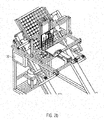
- Fig. 1 is a schematic cross-sectional view of an embodiment of an egg inspection device shown.
- the egg inspection device contains a feed device 1, a lifting device 2, a sampling device 3, a sample receiving device 4, a rinsing device 5 and a control unit 6.
- the lifting device 2 contains an egg stamp 7 and a stop element 8.
- the control unit 6 controls, according to actuators A1, A2, A3, A4, A5, A6, A7 to set or move the aforementioned elements or units.
- the lifting device is a mechanical lifting device with the egg punch 7 and the stop element 8
- a lifting device operated by means of an air flow can also be provided in which the egg is lifted by means of an air flow.
- the egg can be lifted out by means of a stream of air and, for example, pressed against a stop element in order to be brought into the correct position.
- a hose with an opening is positioned under the egg in the tray, and the egg is lifted in the air stream by means of compressed air.
- a guided lifting of the egg is advantageous; this can be done via the egg stamp, preferably rotatably mounted egg stamp, and / or via an air stream.
- the egg is then used by the other Side held in position with a soft suction device, for example.
- This fixation can also take place mechanically and / or by means of an air flow.
- a sliding guidance of the egg position can take place ventrally.
- the feed device 1 has a first actuator A1, the lifting device 2 from the egg punch 7 and the stop element 8 a second actuator A2, which sets the stop element 8, and a third actuator A3, which sets the egg punch 7.
- a first actuator A1 the lifting device 2 from the egg punch 7 and the stop element 8
- a second actuator A2 which sets the stop element 8
- the fourth actuator A4 shown in the figure is drawn up by the syringe 9 shown in this figure.
- a base plate 10 with the syringe 9 attached to it forms a sampling unit, the syringe 9 forming the sampling device.
- the sampling unit as a whole is placed via a fifth actuator A5.
- a sixth actuator A6 is assigned to the sample receiving unit 4 and a seventh actuator is assigned to the flushing device 5.
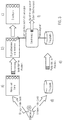
- FIG 2A a supervision of the in Fig. 1 shown egg inspection device, wherein a tray 13 is shown positioned in a starting position.
- a sampling device 9 on the sampling unit, but sampling takes place via cannulas 12 connected to vacuum hoses 11, each cannula with vacuum hose 11 connected to it forming a sampling unit 9, and accordingly five sampling units are provided in the sampling unit. Any number, in particular 5, 10, 15, sampling units 9 can be combined into one unit between one and a multiplicity of sampling units.
- FIG 2A a starting position is shown after the tray 13 has been inserted into the feed device 1 as in the present case, for example half filled with eggs 19.
- the feed device 1 is designed as a type of frame 14 in which the shelf 13 can be inserted in such a way that its side delimiting walls are essentially flush with the frame 14.
- This frame has, on two opposite sides in the transverse direction of the device, a slide 15, which is slidably mounted on corresponding rails 16 and thus by means of the in Figure 2A first actuator A1, not shown, via the control unit 6 from the in Figure 2A starting position shown in an in Figure 2B shown end position can be moved.
- the direction of gravity ie the direction in Fig. 1 , 2A and 2 B from top to bottom as the y-axis
- the axis perpendicular to this vertical ie to the y-axis and transversely to the tray 13 as the z-axis and the axis in which the inclination of the tray 13 extends as the x-axis
- the first actuator A1 ensures a translational movement of the feed device 1 in the yx plane.
- the second actuator A2 and the third actuator A3 ensure a translational movement of the individual elements of the lifting device within the yx plane and perpendicular to the movement of the first actuator A1.
- the fourth or fifth actuator A4, A5 ensures a translational movement of the corresponding elements (sampling device or sampling unit) in the y direction.
- the seventh or eighth actuator A7, A8 ensures a translational movement of the corresponding elements in the x direction.
- the tray 13 is designed as a type of grid 17 with meshes of the same size, with a single egg 18 being able to be held in each mesh. Since the meshes are limited only by strip-like upright walls, each egg 18 lies with its point downward in the respective mesh. That is, in Figure 2A a base side of the eggs 18 is shown.
- the eggs 18 lie in a matrix, in the present example five eggs 18 lying next to one another in the transverse direction (z-axis) and 17 eggs lying one behind the other in the longitudinal direction or oblique direction (x-axis).
- the direction of the z-axis is always referred to as next to one another for the eggs and the translation direction (x-axis) of the feed device 1 is always referred to one behind the other.
- each sampling device 3 is designed as a module which can be attached to the base plate 10 via screw connections, for example.
- a stop surface 19 is provided, from which the cannula 12 protrudes.
- the cannula 12 is held between the plate elements 21, 22 of the module by means of a type of clamping connection, in that the plate element 22 is fastened by means of the in Figure 4B shown two fastening elements 20, which are Allen screws in the present case, is pressed together.
- a vacuum hose 11 is connected to the rear of each cannula 12, which is preferably a thin metal cannula with a sharp point.
- the vacuum hoses 11 are connected to a pneumatic system not shown in detail in the figures. With the negative pressure generated in the pneumatic system, a predetermined amount of liquid can be removed from the egg 18 after a respective egg has been pierced with the cannula 12.
- the egg 18 is positioned.
- the feed device 1 is moved via the control unit 6 in such a way that the first row of eggs, seen in the translation direction of the shelf (x-axis), is level with the sampling device 3 (cf. Figure 2A ) comes to a standstill (step b) in Fig. 3 ).
- the sampling device 3 cf. Figure 2A
- step b) in Fig. 3
- five eggs are arranged under the respective 5 sampling devices 3 of the sampling unit.
- the in Fig. 6 egg stamps 7 shown the five eggs are simultaneously pressed out through the meshes of the tray 13 essentially perpendicular to the tray 13, i.e. perpendicular to the surface formed by the frame 14 of the testicle 13, or perpendicular to the inclined feed plane to be dug out of the horde 13 and against the in Fig. 1 schematically shown stop element 8 pressed.
- the eggs are lifted out of the tray with their thicker back, aligned at an inclined angle between 20 and 80 °.
- the angle ⁇ (compare Fig. 1 ) between the axis of rotation (longitudinal direction) of the egg 18 and the vertical direction (y-axis), ie the direction in which the cannula 12 is pierced into the egg 18 (in the present case the direction in which the sampling unit can be moved in its vertical direction ), due to the trigonometry, corresponds to the angle ⁇ at which the feed device 1 feeds the tray 13 at an angle (cf. Fig. 1 ).
- the angle ⁇ between the axis of rotation (longitudinal direction) of the egg 18 and the cannula 12 corresponds to the angle ⁇ between the x-axis (in the present case the bottom surface) and the direction of translation of the feed device 1, since their legs are perpendicular to one another in pairs.
- the direction in which the eggs are lifted is perpendicular to the plane of the tray, which corresponds to the plane of translation.
- the complete base plate 10 with the sampling devices 3 attached to it i.e. the sampling unit, is moved down on the y-axis so that the five cannulas 12 simultaneously pierce the five eggs 18 lying next to one another.
- the preset target amount of the liquid removed from the egg is shown schematically in Figure 4B shown light barrier 25 detected. That is, as soon as the liquid meniscus in the vacuum hose 11 reaches the light barrier 25, the pressure is kept constant.
- the sampling unit is then withdrawn again (in the vertical direction; y-axis) and the cannulas 12 are withdrawn from the eggs.
- the tips of the cannulas 12 should preferably come to a stop at such a height that the sample receiving device 4 or the rinsing device 5 by means of the device shown in FIG Fig. 1 illustrated sixth and seventh actuator A6, A7, as the arrows in Fig. 1 specify, from the sample dispensing and cleaning group provided with reference numeral 26 can be moved translationally under the cannula tip.
- sample receiving devices 4 i.e. for example cavities
- a matrix of sample receiving devices 4 results.
- step e By means of control by the control unit 6, after translational movement of the titer plate (in the x-axis) under the cannula ends (step e) in Fig. 3 )., the appropriate pressure is now applied to the vacuum hoses 11, so that the amount of liquid removed from the eggs 18 is discharged from the sampling unit devices 3 into the corresponding sample receiving device 27 provided underneath. This takes place essentially simultaneously, so that after five quantities of liquid have been removed from five eggs 18 at the same time in the present example, and again from five liquid samples, one in each case is dispensed into the corresponding sample receiving device.
- the corresponding titer plate (step d) in Fig. 3 ) is previously placed in the egg inspection device by the operator, just like the tray with the eggs.
- estrone sulfate concentration in the allantoic fluid removed from the eggs 18 is determined in order to be able to infer the sex of the embryonic chicks.
- concentration of estrone sulfate concentration in the allantoic fluid removed from the eggs 18 is determined in order to be able to infer the sex of the embryonic chicks.
- One such method for the biological determination of the estrone sulfate concentration for identifying female and male chicken embryos is described in the German patent application application number 10 2015 226 490.4 described. Based a colorimetric measurement can indirectly determine the concentration of estrone sulfate.
- the five eggs 18 held by the lifting device are placed back into the position of the tray (step c) in FIG Fig. 3 ). Alternatively, this can also take place immediately after the liquid has been taken and before the sample is dispensed.
- the titer plate ie the matrix of sample receiving devices 4, is returned to their in Figure 2B or 1 basic position shown in the sample dispensing and cleaning assembly moved.
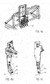
- the rinsing device 5 which in the present example consists of a tub 28 which is filled with alcohol and a collecting vessel 29, is now operated by means of the seventh actuator A7 (cf. Fig. 1 ), as in Fig. 7 shown moved from the basic position within the sample dispensing and cleaning assembly into a rinsing position, not shown in the figure, in which the rinsing device 7 comes to a stand essentially below the cannulas 12, ie below the respective sampling device 3.
- the cannulas can be cleaned after each lancing process (step f) in Fig. 3 ).
- the sampling unit is moved vertically downwards, i.e. on the y-axis, in order to immerse the cannulas 12 with their tips in the tub 28 with alcohol.
- a little alcohol is now sucked from the tub 28 into the cannula via the control unit 6 in order to denature the biological residues.
- the sampling unit is then withdrawn upwards in the vertical direction (along the y-axis) via the fifth actuator A5 and the collecting vessel 29 is moved from the rinsing position into a rinsing liquid dispensing position, so that the collecting vessel 29 is arranged under the sampling device 3.
- Demineralized water which is stored in a container of the device (not shown in the figures), is then introduced into the cannulas 12 via the vacuum hoses and the cannulas 12 are rinsed with this water, which is collected in the collecting vessel 29.
- the cannulas and / or the vacuum tubes are preferably dried. This can be done, for example, by means of separate air nozzles which are provided in the examination device and which inflate the cannulas 12 from the outside. In the present Exemplary embodiment, air is blown through the vacuum hoses 11 and thus the cannulas 12 by means of the pneumatic system.
- the flushing device 5 is again in the basic position, as shown in FIG Fig. 1 is shown withdrawn.
- the feed device 1 is set via the control unit 6 in such a way that the tray 13 is displaced obliquely forward one row at a time in the translation direction in order to sample the next row of five eggs 18 at the same time.
- the position in the matrix of sample receiving devices 4 in which the amount of liquid removed is placed on the titer plate corresponds to the position of the eggs in the trays. In this way, a single sample receiving device can be clearly assigned to each egg in the testicle.
- the entire egg inspection device can be operated via a touch-sensitive computer screen which is connected to the control unit 6.
- the computer screen is in the Figure 2A and B. provided with reference number 30.
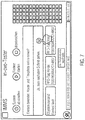
- FIG Fig. 7 An example of a user interface of the software by means of which the device which is displayed on the computer screen 30 is controlled is shown in FIG Fig. 7 shown.
- Fig. 7 a state of the user interface is shown in which the sampling procedure has been carried out once to the end. Therefore, in the schematic arrangement of the eggs in the hordes shown on the right, the squares are filled in.
- each tray and the corresponding titer plate into which the samples are dispensed can be clearly assigned to one another. In the present example, this is ensured by means of an RFID tag, which is provided on a testicle and on the titer plate. A tray number stored in the RFID tag can be assigned a titer plate number accordingly.
- the characterization is usually not carried out within the device according to the invention but in a separate one Contraption.
- the titer plates filled with samples are removed from the device and fed to a corresponding device to determine the estrone sulfate concentration. Because the arrangement of the eggs in trays is known and the position in which sample receiving device the corresponding liquid is dispensed from a respective egg of the tray, it can also be determined later which egg in the tray corresponds to which result on the titer plate.
- the egg size can also vary depending on the age of the laying hens, it is often difficult to sample all eggs with the same cannula length (protrusion of the cannula from the stop surface 19). This is because the protruding cannula length determines the depth from which the corresponding amount of liquid is removed from the egg 18. For example, in order to remove allantoic fluid, a predetermined depth must always be reached at a previously described angle.
- the protruding length of the cannula can be adjusted by means of the control unit.
- the control unit can adjust and vary the length of the cannula from the control unit depending on information about the respective egg, and thus selectively specify a depth for each corresponding egg depending on its properties, such as its thickness, from which the amount of liquid is taken becomes.
- control unit can move the sampling device forward until the cannula is immersed in the liquid in the egg (allantois).
- the control unit can, for example, detect the immersion of the cannula in a liquid (allantois) and stop the forward movement of the sampling unit when the desired depth is reached. Then, for example, the suction process is started.
- the length adjustment of the cannulas can also constitute an invention in itself independently of the egg examination device.
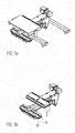
- FIGs 5A and 5B A detailed view of the sample delivery and cleaning assembly 26 is shown. This has a cover 35 for protection against environmental influences such as dust, a first storage surface 36 on which the flushing device 5 rests, and a second storage surface 37 on which the sample receiving devices 4 combined in the titer plate are positioned. As in Figure 5B shown, two titer plates are provided here. Instead of the titer plate, a fleece can also be provided in which the sample taken is released at various points.
- Each of the two storage areas are each attached to a translationally movable arm.
- the two arms can move via the seventh actuator A7, the rinsing device 5 or the titer plate / fleece independently of one another from the basic position into the corresponding dispensing position for the sample receiving unit or for rinsing or blow-out position for the rinsing unit.
- the cleaning assembly 26 can also form an invention in itself independently of the egg inspection device.
- the egg stamps 24 are designed as slightly conical plastic sleeves 39, which have an element 38 made of regulating and compensating material, for example compressible material, in their center.
- the egg stamps 24 are driven by the pistons attached to the underside of the in Fig. 1 third actuator A3 shown moved translationally.
- the tip of the eggs is brought into contact with the element 38 made of regulating and compensating material and the eggs are supported by the conical plastic sleeves 39, which are designed as suction cups comprising egg heads, in their circumferential direction.
- each egg 18 it is advantageous, for example, to determine the size and shape of each egg 18 by means of an observation device, such as a camera, in order to obtain information about the properties or position of each egg by means of image processing methods.
- This information can be passed on to the control device 6, which then adjusts the length accordingly for the respective cannula 12 of the respective sampling unit 3 via the actuators of the sampling devices.
- a connection with a camera and light source for aligning the egg is conceivable.
- samples are taken from five eggs at the same time.
- Sampling is not limited to five eggs. A single one is sufficient for the present invention Sampling unit off. Preferably, however, at least two, in particular up to ten eggs can be sampled at the same time.
- a simple syringe can alternatively be provided, as in the first exemplary embodiment, which can be actuated via a mechanical piston.
- the egg examination device it is particularly effectively possible to pierce the eggs in an automated manner at an oblique angle, whereby preferably the sampling device, ie the cannula arranged on it, is pierced in a vertical direction, ie in the direction of gravity, with each egg individually is slightly inclined at an angle of 20 ° to 80 °.
- the eggs stored in the trays together with the tray are fed in at an angle to the direction of gravity via the feed device and then lifted out of the respective mesh of the tray by means of the lifting device perpendicular to this inclined surface.
- the eggs are held in the lifting device, in the present case by means of plastic sleeves 39, which are formed as suction cups comprising egg heads, and the stop element individually at the side, front and back and independently of the tray, in order to ensure selective, precise piercing at a predefined angle and eggs to be sampled ..
- the angle at which the feed device 1 feeds the eggs essentially corresponds to the inclined position of the eggs in relation to the cannula 12.
- angle ranges are between 30 ° and 60 °, preferably between 40 ° and 50 °, in particular 45 °.
- the allantoic fluid collects to a suitable extent at a well-defined location in the egg, so that a well-defined amount of allantoic fluid can be removed by means of the cannula.
- the tip of the cannula used has at least two openings. It has been found that if only one opening is used, ideal sampling is not possible under all conditions is achieved. More than two openings in the cannula are also possible. In some circumstances a single opening in the cannula may also be advantageous.
- a UV lamp unit 41 (cf. Fig. 1 ) can be provided so that UV light is emitted by this UV lamp unit 41 onto the region where the eggs are sampled.
- a UV tube for example, can be used which extends along the z-axis, i.e. along the direction of the eggs lying next to one another.
- placing the UV lamp unit 41 between the sampling unit 3 and the sample dispensing and cleaning assembly 26 is advantageous.
- the inclination with which the feed device 1 feeds the tray can also be changed selectively as a function of egg characteristics.
- the settings of the entire device can take place via the control unit 6.
- this image information can be processed in order to selectively determine the positioning of the individual eggs for removing the amount of liquid, and / or depending on the egg thickness, the egg size, and / or determine the cannula length.
- the vacuum hoses can be designed in such a way that their pressure can be set variably and independently of one another.
- the individual sampling devices being attached to a base plate, it can also be advantageous that the individual sampling devices can be moved relative to one another.
Description
Die vorliegende Erfindung betrifft eine Eieruntersuchungseinrichtung, insbesondere eine Eiergeschlechtsbestimmungseinrichtung. Eine gattungsbildende Eieruntersuchungseinrichtung mit den oberbegrifflichen Merkmalen von Anspruch 1 ist beispielsweise aus der
In der
So wird beispielsweise eine vorherbestimmte Flüssigkeitsmenge an Allantoisflüssigkeit aus den Eiern entnommen, um beispielsweise das Geschlecht der embryonalen Küken zu bestimmen.For example, a predetermined amount of allantoic fluid is removed from the eggs in order to determine the sex of the embryonic chicks, for example.
Eine Vielzahl von Eiern wird in einer gitterförmigen Anordnung in einer Horde aufgenommen. In der Horde liegen die Eier in deren horizontaler Richtung, d.h. die Rotationsachse des Eis ist senkrecht zur Schwerkraftrichtung ausgerichtet. Da die Eier in der Horde nicht verdrehfest angeordnet sind, werden die Eier in der Vorrichtung der
Danach wird die Schale mittels einer dünnen Kanüle punktiert, die an einer Probeentnahmeeinrichtung vorgesehen ist, die von der Seite in das Ei hineinsticht, d.h. senkrecht zur Horizontalrichtung des Eies, um eine Flüssigkeitsmenge zu entnehmen.Thereafter, the shell is punctured by means of a thin cannula, which is provided on a sampling device, which pierces the egg from the side, i.e. perpendicular to the horizontal direction of the egg, in order to withdraw a quantity of liquid.
Das in diesem Stand der Technik beschriebene Verfahren ist relativ ungenau, weil eine Positionierung der Eier und damit eine Entnahme von Flüssigkeit an einem spezifischen Ort innerhalb des Eis nicht immer gewährleistet ist.The method described in this prior art is relatively imprecise because positioning of the eggs and thus removal of liquid at a specific location within the egg is not always guaranteed.
Die
In der
Ausgehend hiervon schlägt die Erfindung zur Lösung des zuvor genannten Problems eine Eieruntersuchungseinrichtung nach Anspruch 1 vor.Based on this, the invention proposes an egg examination device according to claim 1 to solve the above-mentioned problem.
Diese zeichnet sich dadurch aus, dass die Zuführeinrichtung derart ausgebildet ist, dass diese die Horde unter einem schrägen Winkel von zwischen 20° und 80° zu einer Ebene senkrecht zur Richtung der Schwerkraft zu der Probeentnahmeeinrichtung zuführt, und eine Aushebeeinrichtung vorgesehen ist, mittels welcher das Ei aus der Horde heraushebbar ist und mittels welcher das Ei in eine Probenahmeposition verbringbar ist, in welcher es von der Probenentnahmeeinrichtung schräg zu seiner Rotationsachse anstechbar ist und dem Ei mittels der Probeentnahmeeinrichtung die zu entnehmende Flüssigkeitsmenge entnehmbar ist, wobei die Aushebeeinrichtung mittels der Kontrolleinheit steuerbar ist.This is characterized in that the feed device is designed in such a way that it feeds the tray at an inclined angle of between 20 ° and 80 ° to a plane perpendicular to the direction of gravity to the sampling device, and a lifting device is provided by means of which the Egg can be lifted out of the tray and by means of which the egg can be brought into a sampling position in which it can be pierced by the sampling device at an angle to its axis of rotation and the egg can be pierced by means of the Sampling device, the amount of liquid to be removed can be removed, the extraction device being controllable by means of the control unit.
Gerade bei der Entnahme von Allantoisflüssigkeit hat sich gezeigt, dass, wenn die Eier nicht senkrecht zur Horizontalen sondern leicht schräg zur Rotationsachse, vorzugsweise schräg von dessen Rückseite angestochen werden, ein Bereich innerhalb des Eies getroffen wird, um in reproduzierbarer Weise vorherbestimmte Flüssigkeitsmengen zu entnehmen. Wenn das Ei um den zuvor beschriebenen Winkel in Bezug mit dessen Basis verdreht ist, sammelt sich die Allantoisflüssigkeit in geeignetem Maße an einer wohl definierten Stelle im Ei, so dass eine gewünschte Menge Allantoisflüssigkeit mittels der Kanüle entnommen werden kann. Besonders vorteilhafte Winkelbereiche sind zwischen 30° und 60°, vorzugsweise 40° bis 50°, insbesondere 45°. Die entsprechenden Winkelbereiche können für sich jeweils obere bzw. untere Grenzen der Eiausrichtung bilden. Zudem hat sich gezeigt, dass unter den zuvor beschriebenen Winkelbereichen eine gute Einstichkraft gewährleistet ist, ohne eine nachhaltige Beschädigung der Schale, welche zu einem Zerbrechen des Eis führt. Da die Eier entweder horizontal oder vertikal in der Horde liegen, insbesondere vertikal, d.h. dass die Längsachse der Eier senkrecht zu der Hordenebene ausgebildet ist, ergibt sich ein entsprechender schräger Winkel, mit welchem die einzelnen Eier von der Aushebeeinheit zu der Probeentnahmeeinrichtung transferiert werden. Von der Aushebeeinheit werden die Eier vorzugsweise senkrecht zu der Horde bzw. der von der Hode gebildeten Fläche, bzw. senkrecht zur schrägen Zuführebene, vorzugsweise durch die Maschen der Horde hindurch herausgebracht und z.B. durch eine entsprechende Einrichtung in dieser Position fixiert . Nachdem ein solches Ei beprobt ist, d.h. eine entsprechende Flüssigkeitsmenge diesem entnommen ist, kann es mit der Aushebeeinrichtung wieder zurück in die Horde verbracht werden und die Horde wird vorzugsweise translatorisch in dem gleichen schrägen Winkel weiter bewegt, um das nächste Ei in der Horde zu beproben. So können im Wesentlichen alle in der schrägstehenden Horde schräg hintereinander angeordneten Eier nacheinander beprobt werden. Das jeweilige Ei wird für die Probeentnahme mittels der Probeentnahmeeinrichtung aus der Horde mittels einer Aushebeeinrichtung herausgehoben und in der Probenahmeposition positioniert. Da die Horden schon schräg zugeführt werden, können die Eier somit während sie einzeln ausgehoben sind, schräg angestochen werden.Particularly when removing allantoic fluid, it has been shown that if the eggs are pierced not perpendicular to the horizontal but slightly obliquely to the axis of rotation, preferably obliquely from its back, an area within the egg is hit in order to reproducibly withdraw predetermined amounts of fluid. When the egg is rotated by the angle described above with respect to its base, the allantoic fluid collects to a suitable extent at a well-defined location in the egg, so that a desired amount of allantoic fluid can be withdrawn by means of the cannula. Particularly advantageous angle ranges are between 30 ° and 60 °, preferably 40 ° to 50 °, in particular 45 °. The corresponding angular ranges can in each case form upper or lower limits of the egg orientation. In addition, it has been shown that a good puncture force is guaranteed under the angle ranges described above, without lasting damage to the shell, which leads to breaking of the egg. Since the eggs lie either horizontally or vertically in the tray, in particular vertically, i.e. the longitudinal axis of the eggs is perpendicular to the tray plane, there is a corresponding inclined angle at which the individual eggs are transferred from the lifting unit to the sampling device. From the lifting unit, the eggs are brought out preferably perpendicular to the tray or the surface formed by the testicle, or perpendicular to the inclined feed plane, preferably through the mesh of the tray and, for example, fixed in this position by a corresponding device. After such an egg has been sampled, ie a corresponding amount of liquid has been removed from it, it can be brought back into the tray with the lifting device and the tray is preferably moved further in translation at the same oblique angle in order to sample the next egg in the tray . Essentially all of the eggs arranged in the inclined tray behind one another can be sampled one after the other. For the sampling, the respective egg is lifted out of the rack by means of a lifting device by means of the sampling device and positioned in the sampling position. Since the trays are fed in at an angle, the eggs can be pierced at an angle while they are individually lifted out.
Gemäß einer Weiterbildung der Erfindung kann die Aushebeeinrichtung derart konfiguriert sein, dass diese ein mit dieser ausgehobenes Ei in eine vorgegebene Einstechposition rotieren kann. Wenn das Ei mittels der Aushebeeinrichtung aus der Horde gehoben wird kann es vorkommen, dass dieses nicht in einer Position ist, in der idealerweise die Probename stattfindet. Oft kann das Ei durch Rotation, z.B. um dessen Längs- und/oder Querachse rotiert werden um in eine bessere Pobeentnahmeposition gebracht zu werden. Dies kann zum Beispiel durch Rütteln, oder auch durch elektrisch angetriebene Rollen an der Aushebeeinrichtung gewährleistet werden.According to a further development of the invention, the lifting device can be configured in such a way that it can rotate an egg lifted with it into a predefined piercing position. If the egg is lifted out of the tray by means of the lifting device, it may happen that it is not in a position in which ideally the sampling takes place. Often the egg can be rotated by rotation, for example about its longitudinal and / or transverse axis, to turn it into a better sample removal position to be brought. This can be ensured, for example, by shaking or by electrically driven rollers on the lifting device.
Gemäß einer Weiterbildung der Erfindung kann die Aushebeeinrichtung eine mechanische Aushebeeinrichtung sein, oder eine mittels eines Luftstroms betriebene Aushebeeinrichtung, in der das Ei mittels eines Luftstromes ausgehoben wird. Soweit es sich um eine mechanische Aushebeeinrichtung handelt ist eine Ausgestaltung, wie sie weiter unten erläutert wird mit einem Eierstempel und einem Anschlagselement vorteilhaft. Das Ei kann aber auch mittels eines Luftstromes herausgehoben werden, und z.B. gegen ein Anschlagselement gedrückt werden um in die richtige Position gebracht zu werden. In diesem Fall wird ein Schlauch mit einer Öffnung unter dem Ei in der Horde positioniert, und mittels Druckluft das Ei in dem Luftstrom angehoben.According to a further development of the invention, the lifting device can be a mechanical lifting device, or a lifting device operated by means of an air flow, in which the egg is lifted by means of an air flow. As far as a mechanical lifting device is concerned, an embodiment as explained below with an egg punch and a stop element is advantageous. The egg can also be lifted out by means of a stream of air and, for example, pressed against a stop element in order to be brought into the correct position. In this case, a hose with an opening is positioned under the egg in the tray, and the egg is lifted in the air stream by means of compressed air.
Um die Positionierung und Ausrichtung des zu beprobenden Eies zu ermöglichen ist eine geführte Anhebung des Eies vorteilhaft, diese kann über den Eierstempel, vorzugsweise rotierbar gelagerten Eierstempel geschehen und/oder über einen Luftstrom. Das Ei wird dann von der anderen Seite z.B. mit einem weichen Sauger in Position gehalten. Diese Fixierung kann auch mechanisch und/oder über Luftstrom erfolgen. Zudem kann ventral eine gleitende Führung des Eies in Position erfolgen.In order to enable the egg to be sampled to be positioned and aligned, it is advantageous to raise the egg in a guided manner; this can be done via the egg stamp, preferably rotatably mounted egg stamp, and / or via an air stream. The egg is then held in position from the other side, e.g. with a soft teat. This fixation can also take place mechanically and / or by means of an air flow. In addition, the egg can be glided into position ventrally.
Gemäß einer Weiterbildung der Erfindung kann die Probeentnahmeeinrichtung eine Kanüle aufweisen, welche mit einer Vakuumerzeugungseinrichtung verbunden ist, wobei die aus dem Ei zu entnehmende Flüssigkeitsmenge mittels der Kontrolleinheit über den in der Vakuumerzeugungseinrichtung erzeugten Druck steuerbar ist.Die Kontrolleinheit kann ein Pneumatiksystem steuern, welches zum Beispiel von einem Vakuumschlauch, welcher mit der Kanüle verbunden ist gebildet wird, welcher an einen Vakuumgenerator angeschlossen ist. Über die Steuerung des Druckes kann eine wohl definierte Menge Flüssigkeit aus dem Ei entnommen werden, nachdem die Kanüle schräg in die Eierschale hineingestochen ist. Durch ein solches pneumatisches System und eine Probenahme über eine Vakuumsteuerung können mechanische Elemente, wie sie z.B. bei der Verwendung einfacher Kolbenspritzen als Probeentnahmeeinrichtung vorhanden sind, reduziert werden. Die Probeentnahmeeinrichtung mit der davon ausragenden Kanüle kann zur Probenahme in vertikaler Richtung, d.h. in Schwerkraftrichtung, bewegt werden, wobei die Kanüle bzw. die Spitze der Kanüle die Eierschale durchsticht und die entsprechende vorbestimmte Flüssigkeitsmenge, beispielsweise aus der Allantois, entnimmt. Bevorzugte Kanülenaußendurchmesser sind 0,55 mm; 0,60 mm; 0,65 mm; 0,70 mm; 0,75 mm; 0,80 mm und bevorzugte Kanüleninnendurchmesser sind 0,10 mm; 0,15 mm; 0,20 mm, 0,25 mm, 0,30 mm; 0,35 mm; 0,40 mm; 0,45 mm; 0,50 mm. Die zuvor genannten Werte können jeweils für sich obere bzw. untere Grenzen eines Kanülendickenbereiches bilden.According to a further development of the invention, the sampling device can have a cannula which is connected to a vacuum generating device, the amount of liquid to be removed from the egg being controllable by means of the control unit via the pressure generated in the vacuum generating device is formed by a vacuum hose, which is connected to the cannula, which is connected to a vacuum generator. By controlling the pressure, a well-defined amount of liquid can be withdrawn from the egg after the cannula has pierced the eggshell at an angle. Such a pneumatic system and sampling via a vacuum control can reduce mechanical elements, such as those that are present when using simple piston syringes as a sampling device. The sampling device with the cannula protruding therefrom can be moved for sampling in the vertical direction, ie in the direction of gravity, the cannula or the tip of the cannula piercing the egg shell and taking the corresponding predetermined amount of liquid, for example from the allantois. Preferred outer diameter of the cannula are 0.55 mm; 0.60 mm; 0.65 mm; 0.70 mm; 0.75 mm; 0.80 mm and preferred inner cannula diameters are 0.10 mm; 0.15mm; 0.20 mm, 0.25 mm, 0.30 mm; 0.35mm; 0.40 mm; 0.45mm; 0.50 mm. The aforementioned values can each form upper or lower limits of a cannula thickness range.
Gemäß einer Weiterentwicklung der Erfindung kann die Probeentnahmeeinrichtung einen Kanülenrevolver mit mehreren Kanülen aufweisen. Ein Kanülenrevolver kann als drehbare Einrichtung vorgesehen sein, in der, vorzugsweise mittels der Kontrolleinheit, die Kanüle nach jedem Stechen rotiert wird. So kann für jedes Stechen eine neue bzw. andere Kanüle verwendet werden. Hierdurch ist eine schnellere Verfahrensführung gewährleistet. Vorzugsweise kann nämlich, gleichzeitig während die andere Kanüle zum stechen verwendet wird, die Kanüle, mit der zuvor in das Ei gestochen wurde, gereinigt werden. Ein Stechen und Säubern der Nadel in einem Schritt kombinieren kann Zeit bei der Beprobung und Reinigung sparen kann. Der Kanülenrevolver kann mehreren Nadeln insbesondere 6 Nadeln aufweisen.According to a further development of the invention, the sampling device can have a cannula turret with several cannulas. A cannula revolver can be provided as a rotatable device in which the cannula is rotated after each lancing, preferably by means of the control unit. This means that a new or different cannula can be used for each lancing. This ensures that the process is carried out more quickly. This is because preferably, at the same time as the other cannula is being used for piercing, the cannula with which the egg was previously pierced can be cleaned. Combining pricking and cleaning the needle in one step can save time on sampling and cleaning. The cannula turret can have several needles, in particular 6 needles.
Gemäß einer Weiterbildung der Erfindung kann die Kanüle zumindest zwei Öffnungen enthalten, mittels welcher die zu entnehmende Flüssigkeitsmenge aus dem Ei entnehmbar ist. Es hat sich gezeigt, dass es manchmal, weil die Position von Membranen innerhalb des Eis auch bei immer gleicher Ausrichtung des Eis nicht dieselbe ist, soweit nur eine einzige Öffnung an der Spitze der Kanüle vorgesehen ist, zu Problemen bei einer Flüssigkeitsentnahme kommen kann, weil eine solche Membran die Öffnung verdeckt. Soweit zumindest zwei Öffnungen, insbesondere genau zwei Öffnungen, vorgesehen sind, ist es unwahrscheinlich, dass alle beiden Öffnungen gleichzeitig verdeckt werden.According to a further development of the invention, the cannula can contain at least two openings, by means of which the amount of liquid to be removed can be removed from the egg. It has been shown that sometimes, because the position of membranes within the egg is not the same even if the egg is always in the same orientation, as long as only a single opening is provided at the tip of the cannula, problems can arise during fluid removal because such a membrane covers the opening. If at least two openings, in particular exactly two openings, are provided, it is unlikely that both openings will be covered at the same time.
Gemäß einer Weiterbildung der Erfindung kann eine überstehende Länge der Kanüle, mit welcher diese vom einen an der Probeentnahmeeinrichtung vorgesehenen Anschlagsfläche, welche bei Probenahme mit dem Ei in Kontakt kommt, abragt, einstellbar sein. Da die in einer Horde angeordneten Eier, z.B. in Abhängigkeit des Legealters der Henne oder der Genetik, unterschiedlich groß sein können, kann beispielsweise in Abhängigkeit der Eiergröße eine unterschiedliche Stichtiefe der Kanüle notwendig sein, um die Flüssigkeitsmenge aus dem Ei zu entnehmen. Die optimale Stichtiefe kann automatisch über bildgebende Verfahren ermittelt werden. Die überstehende Länge der Kanüle wird vorzugsweise, für jedes Ei automatisch angepasst.According to a further development of the invention, a protruding length of the cannula, with which it protrudes from a stop surface provided on the sampling device, which comes into contact with the egg during sampling, can be adjustable. Since the eggs arranged in a horde can vary in size, e.g. depending on the laying age of the hen or the genetics, a different penetration depth of the cannula may be necessary, depending on the egg size, in order to remove the amount of liquid from the egg. The optimal stitch depth can be determined automatically using imaging methods. The protruding length of the cannula is preferably automatically adjusted for each egg.
Die Probeentnahmeeinrichtung wird, nachdem eine eindeutige Beprobungssituation gefunden wurde, beispielsweise immer solange in vertikaler Richtung auf das Ei gedrückt bis die Kanüle komplett im Ei verschwunden ist. Über eine Regeleinrichtung kann das Eintauchen der Nadel in Flüssigkeit/Allantois bestätigt werden und der definierten Ansaugvorgang gestartet werden.After an unambiguous sampling situation has been found, the sampling device is for example always pressed in the vertical direction onto the egg until the cannula has completely disappeared in the egg. The immersion of the needle in the liquid / allantois can be confirmed via a control device and the defined suction process can be started.
Es kann auch zum Beispiel detektiert werden sobald das Ei an einer Anschlagsfläche der Probeentnahmeeinrichtung anschlägt. Sobald diese Anschlagfläche von dem Ei berührt wird, was beispielsweise mittels optischer Methoden, wie mittels einer Kamera, oder mittels eines Drucksensors an der Anschlagsfläche gemessen werden kann, instruiert die Kontrolleinheit die Probeentnahmeeinrichtung zum Stoppen deren Bewegung. Die Länge der Kanüle, die aus der Probeentnahmeeinrichtung herausragt bestimmt demnach die Tiefe, in der die Flüssigkeit aus dem Ei entnommen wird. Gemäß einer Weiterbildung der Erfindung kann die übererstehende Länge der Kanüle, mittels der Kontrolleinheit einstellbar sein.. So kannbeispielsweise von der Kontrolleinheit die Kontrolleinheit in Abhängigkeit von Informationen über das jeweilige Ei die Länge der Kanüle einstellen und variieren, und so selektiv für jedes entsprechende Ei in Abhängigkeit dessen Eigenschaften, wie z.B. dessen Dicke, eine Tiefe vorgeben, aus der die Flüssigkeitsmenge entnommen wird.It can also be detected, for example, as soon as the egg hits a stop surface of the sampling device. As soon as this stop surface is touched by the egg, which can be measured for example by means of optical methods such as a camera or by means of a pressure sensor on the stop surface, the control unit instructs the sampling device to stop its movement. The length of the cannula that protrudes from the sampling device accordingly determines the depth at which the liquid is removed from the egg. According to a further development of the invention, the protruding length of the cannula can be adjusted by means of the control unit. For example, the control unit can adjust and vary the length of the cannula from the control unit depending on information about the respective egg, and thus selectively for each corresponding egg in Depending on its properties, such as its thickness, specify a depth from which the amount of liquid is taken.
Alternativ oder zusätzlich, oder auch wenn die überstehende Kanülenlänge nicht veränderbar ist kann die Kontrolleinheit die Probeentnahmeeinrichtung vorbewegen, bis die Kanüle in die Flüssigkeit im Ei (Allantois) eintaucht. Die Kontrolleinheit kann z.B. das Eintauchen der Kanüle in eine Flüssigkeit (Allantois) wahrnehmen und die Vorwärtsbewegung der Probeentnahmeeinheit stoppen, wenn die gewünschte Tiefe erreicht ist. Danach wird z.B. mit dem Saugvorgang begonnen.Alternatively or additionally, or even if the protruding cannula length cannot be changed, the control unit can move the sampling device forward until the cannula is immersed in the liquid in the egg (allantois). The control unit can, for example, detect the immersion of the cannula in a liquid (allantois) and stop the forward movement of the sampling unit when the desired depth is reached. Then, for example, the suction process is started.
Gemäß einer Weiterbildung der Erfindung kann die Probeentnahmeeinrichtung eine Lichtschranke ausweisen, über welche mittels der Kontrolleinheit bestimmbar ist, ob die aus dem Ei entnommene Flüssigkeitsmenge der zu entnehmenden Flüssigkeitsmenge entspricht und nicht durch Luftblasen verändert werden. Die Lichtschranke kann in einer Position vorgesehen sein, in der z.B. der Vakuumschlauch oder eine anderes transparentes Element, durch welches die Flüssigkeit eingesogen wird, durchleuchtet wird. Sobald soviel Flüssigkeit über die Kanüle eingesogen ist, dass die vorherbestimmte Flüssigkeitsmenge erreicht ist, kann durch die Lichtschranke der Meniskus bestimmt werden und somit die Menge an aus dem Ei entnommener Flüssigkeit bestimmt werden. Bevorzugte Entnahmemengen von Flüssigkeit können 1 µl bis 50 µl sein, vorzugsweise 5 bis 30 µl, insbesondere 10 bis 20 µl. Die vorgenannten Werte können für sich jeweils obere und untere Grenzen bilden. Gerade bei der Entnahme solcher kleiner Flüssigkeitsmengen hat sich die Bestimmung der entnommenen Flüssigkeitsmenge mittels Lichtschranken als gute Lösung erwiesen, um eine genaue Entnahmemengenbestimmung durchzuführen und ggf. Luftblasen zu erkennen.According to a further development of the invention, the sampling device can have a light barrier via which the control unit can be used to determine whether the amount of liquid removed from the egg corresponds to the amount of liquid to be removed and is not changed by air bubbles. The light barrier can be provided in a position in which, for example, the vacuum hose or another transparent element through which the liquid is sucked in is illuminated. As soon as enough liquid has been sucked in via the cannula that the predetermined amount of liquid has been reached, the meniscus can be determined by the light barrier and thus the amount of liquid removed from the egg can be determined. Preferred amounts of liquid can be 1 μl to 50 μl, preferably 5 to 30 μl, in particular 10 to 20 μl. The aforementioned values can form upper and lower limits for themselves. Especially when removing such small amounts of liquid, determining the amount of liquid removed by means of light barriers has proven to be a good solution in order to carry out an exact determination of the amount of liquid and, if necessary, to detect air bubbles.
Es können auch mehrere Lichtschranken vorgesehen sein, z.B. Lichtschranken die auf unterschiedlich farbigem Licht basieren. So können z.B. auftretende Probleme bei der Messung der Entnahmemenge minimiert werden, in dem Fall wenn in der entnommenen Flüssigkeit rote Blutkörperchen vorhanden sind.Several light barriers can also be provided, e.g. light barriers based on differently colored light. In this way, for example, problems that arise when measuring the amount withdrawn can be minimized in the event that red blood cells are present in the liquid withdrawn.
Gemäß einer Weiterbildung der Erfindung können zumindest zwei Probeentnahmeeinrichtungen vorgesehen sein, welche in einer Probenahmeeinheit zusammengefasst sind, sodass durch jede Probeentnahmeeinrichtung der zumindest zwei gleichzeitig die zu entnehmende Flüssigkeitsprobe jeweils einem Ei der Horde entnehmbar ist, und es können zumindest zwei Aushebeeinrichtungen vorgesehen sein, wobei mittels der jeweiligen Aushebeeinrichtung der zumindest zwei Aushebeeinrichtungen, das der jeweiligen Probenahmeeinheit zugeordnete Ei der Horde aus der Horde aushebbar und in ie Probenahmeposition verbringbar ist. Insbesondere sind mehr als zwei Probeentnahmeeinrichtungen vorgesehen.According to a further development of the invention, at least two sampling devices can be provided, which are combined in a sampling unit, so that the liquid sample to be taken can be removed from one egg of the tray at the same time through each sampling device of the at least two, and at least two extraction devices can be provided, whereby by means of the respective lifting device of the at least two lifting devices, the egg of the tray assigned to the respective sampling unit can be lifted out of the tray and brought into the sampling position. In particular, more than two sampling devices are provided.
So können nach dieser Weiterbildung zumindest zwei Probeentnahmeeinrichtungen vorgesehen sein, denen jeweils eine Aushebeeinrichtung zugeordnet ist, wobei jede Aushebeeinrichtung ein Ei aus der Horde heraushebt und der jeweiligen Probeentnahmeeinrichtung zuführt. So kann für zumindest zwei Eier gleichzeitig eine Probennahme durchgeführt werden. Bei dieser Weiterbildung können auch mehr als zwei Probeentnahmeeinrichtungen und entsprechend mehr als zwei Aushebeeinrichtungen vorgesehen sein, so dass beispielsweise immer drei, vier, fünf oder sogar zehn Eier gleichzeitig beprobt werden können. Die entsprechenden Eier der Horde, die gleichzeitig beprobt werden können, liegen vorzugsweise unmittelbar nebeneinander in einer Reihe der Horde in Querrichtung zu der Schrägstellung der Horde.According to this development, at least two sampling devices can be provided, each of which is assigned a lifting device, each lifting device lifting an egg out of the tray and feeding it to the respective sampling device. Samples can be taken for at least two eggs at the same time. In this development, more than two sampling devices and correspondingly more than two extraction devices can be provided so that, for example, three, four, five or even ten eggs can always be sampled at the same time. The corresponding eggs of the tray, which can be sampled at the same time, are preferably located directly next to one another in a row of the tray in the transverse direction to the inclined position of the tray.
So ist es möglich, dass zum Beispiel immer mindestens zwei oder auch mehr Eier nebeneinander mittels einer Vielzahl von entsprechenden Probeentnahmeeinrichtungen beprobt werden können und nachdem die entsprechende Reihe von Eiern beprobt ist, die Horde um eine Einheit verschoben wird, um die in Schrägrichtung darunterliegende Reihe an Eiern zu beproben.So it is possible, for example, that at least two or more eggs can always be sampled next to one another using a large number of corresponding sampling devices and, after the corresponding row of eggs has been sampled, the tray is shifted by one unit, around the row below in the diagonal direction Eggs to be sampled.
Soweit die Horde nebeneinander (quer zur Schrägstellung) mehr Eier aufweist als Probeentnahmeeinrichtungen vorgesehen sind, kann die Probenahmeeinheit mit den Probeentnahmeeinrichtungen auch in dieser in horizontaler Richtung, also in Richtung der in Reihe nebeneinanderliegenden Eier, mittels der Kontrolleinheit verfahren werden. So können z.B. jeweils zwei bzw. drei bzw. vier bzw. fünf Eier, die in einer Reihe nebeneinander liegen, gleichzeitig beprobt werden. Nach Beproben einer ganzen Eierreihe einer Horde in Horizontalrichtung wird die jeweils nächste Reihe, die in Schrägrichtung darunterliegt, beprobt.If the tray has more eggs next to each other (transversely to the inclined position) than sampling devices are provided, the sampling unit with the sampling devices can also be moved in this horizontal direction, i.e. in the direction of the eggs lying next to each other in a row, by means of the control unit. For example, two or three or four or five eggs in a row can be sampled at the same time. After sampling a whole row of eggs in a tray in the horizontal direction, the next row in each case, which lies underneath in the diagonal direction, is sampled.
Durch die Ausgestaltung mit zumindest zwei Probeentnahmeeinrichtungen mit einer dieser zugerichteten Aushebeeinrichtung, kann ein schnelles Verfahren bereitgestellt werden, so dass gleichzeitig immer mehrere Eier beprobt werden können.As a result of the design with at least two sampling devices with one of these prepared lifting devices, a fast method can be provided so that a plurality of eggs can always be sampled at the same time.
Gemäß einer Weiterbildung kann die Kontrolleinheit derart ausgebildet sein, dass diese für jede der zumindest zwei Probeentnahmeeinrichtungen die aus dem Ei zu entnehmende Flüssigkeitsmenge individuell in Abhängigkeit von Eierparametern des jeweiligen der Probeentnahmeeinrichtung zugeordneten Eies einstellt.According to a further development, the control unit can be designed in such a way that it individually adjusts the amount of liquid to be removed from the egg for each of the at least two sampling devices as a function of the egg parameters of the respective egg assigned to the sampling device.
In Abhängigkeit beispielsweise der Eigröße oder des Bebrütungstags des Eies kann die im Ei enthaltene Menge an Allantoisflüssigkeit abweichen. Somit ist es günstig, in Abhängigkeit von vorher festgestellten Eiparametern die zu entnehmende Flüssigkeitsmenge individuell für jede der zumindest zwei oder mehr Probeeinrichtungen einzustellen. Hierzu kann vorgesehen sein, dass der Druck in den entsprechenden Vakuumschläuchen, die jeder Probeentnahmeeinrichtung zugeordnet sind, individuell eingestellt werden kann, um eine entsprechende Flüssigkeitsmenge zu entnehmen. Auch die Positionierung der vorzugsweise vorgesehenen Lichtschranken zur Bestimmung der entnommenen Flüssigkeitsmenge, kann demnach in Abhängigkeit der zu entnehmenden Flüssigkeitsmenge von der Kontrolleinheit gesteuert werden.The amount of allantoic fluid contained in the egg may vary depending on, for example, the egg size or the day of incubation of the egg. It is therefore advantageous to set the amount of liquid to be removed individually for each of the at least two or more sample devices as a function of previously determined egg parameters. For this purpose, it can be provided that the pressure in the corresponding vacuum hoses, which are assigned to each sampling device, can be set individually in order to withdraw a corresponding amount of liquid. The positioning of the preferably provided light barriers for determining the amount of liquid withdrawn can accordingly be controlled by the control unit as a function of the amount of liquid to be withdrawn.
Gemäß einer Weiterbildung der Erfindung kann die Probeentnahmeeinrichtung in Schwerkraftrichtung bewegbar sein. Darüber hinaus kann die Probeentnahmeeinrichtung parallel zu der Fläche innerhalb der die Horde durch die Zuführeinrichtung translatorisch bewegbar ist, und in Richtung quer zur durch die Zuführeinrichtung vorgeschriebene Translationsrichtung der Horde bewegbar sein.According to a further development of the invention, the sampling device can be movable in the direction of gravity. In addition, the sampling device can be movable parallel to the area within which the shelf can be moved in translation by the feed device, and in the direction transverse to the direction of translation of the shelf prescribed by the feed device.
Insbesondere bewegt sich die Probenahmerichtung in Schwerkraftrichtung sowie in Richtung der einzelnen Eier in Reihen nebeneinander quer zur Translationsrichtung der Horde, das heißt parallel zu der Fläche innerhalb der die Horde durch die Zuführeinrichtung translatorisch bewegbar ist, und in Richtung quer zur durch die Zuführeinrichtung vorgeschriebene Translationsrichtung der Horde. So kann z.B. die Kontrolleinheit einen Aktuator ansteuern, der mit der Probeentnahmeeinrichtung zusammenwirkt. Somit ist die Probeentnahmeeinrichtung zumindest in zwei Richtungen innerhalb einer Ebene verschiebbar. Eine solche translatorische Bewegbarkeit kann sowohl für den Fall einer einzelnen Probeentnahmeeinrichtung als auch für den Fall, dass mehrere Probeentnahmeeinrichtungen in einer Probenahmeeinheit zusammengefasst sind, vorgesehen sein. So ist es nämlich möglich, wenn alle Probeentnahmeeinrichtungen in der Probenahmeeinheit zusammengefasst sind, alle Probeentnahmeeinrichtungen in gleichförmiger Weise simultan zu bewegen. Die Bewegungsrichtung in Schwerkraftrichtung ist dazu vorgesehen, die Probeentnahmeeinrichtung auf das jeweilige Ei zuzufahren, um beispielsweise die Kanüle in die Eierschale hineinzudrücken. Die Bewegung in Translationsrichtung ist beispielsweise dafür vorgesehen, Eier, die in Reihen nebeneinander quer zur Zuführungseinrichtung in der Horde liegen, zu beproben. Soweit alle nebeneinander in der Horde liegenden Eier gleichzeitig mit den in einer Probenahmeeinheit zusammengefassten Probeentnahmeeinrichtungen beprobt werden, kann eine solche Bewegbarkeit in Translationsrichtung auch gänzlich weggelassen werden.In particular, the sampling direction moves in the direction of gravity and in the direction of the individual eggs in rows side by side transversely to the direction of translation of the tray, i.e. parallel to the area within which the tray is translationally movable by the feed device, and in the direction transverse to the translation direction prescribed by the feed device Horde. For example, the control unit can control an actuator that interacts with the sampling device. The sampling device can thus be displaced at least in two directions within a plane. Such translational mobility can be provided both for the case of a single sampling device and for the case that several sampling devices are combined in one sampling unit. This is because it is possible if all sampling devices are combined in the sampling unit, all of them To move sampling devices in a uniform manner simultaneously. The direction of movement in the direction of gravity is intended to move the sampling device towards the respective egg in order, for example, to push the cannula into the egg shell. The movement in the translational direction is provided, for example, to sample eggs lying in rows next to one another across the feed device in the tray. Insofar as all eggs lying next to one another in the tray are sampled simultaneously with the sampling devices combined in a sampling unit, such mobility in the translation direction can also be completely omitted.
Gemäß einer Weiterbildung der Erfindung kann eine Probenaufnahmeeinrichtung vorgesehen sein, welche die von der Probeentnahmeeinrichtung aus dem Ei entnommene aus der Probeentnahmeeinrichtung abgegeben Flüssigkeitsmenge aufnimmt. Eine solche Probeaufnahmeeinrichtung kann jedes Gefäß bzw. auch ein Vlies sein, das der Eieruntersuchungseinrichtung zugeordnet ist, in welches die entnommene Flüssigkeitsmenge aus dem Ei von der Probeentnahmeeinrichtung abgegeben werden kann. Es versteht sich von selbst, dass vorzugsweise jeweils die aus einem Ei entnommene Flüssigkeit in eine entsprechende leere Probeaufnahmeeinrichtung z.B. das leere Gefäß bzw. ein unbenutztes Vlies gegeben wird und demnach so viele Probeaufnahmeeinrichtungen vorgesehen sein können wie Eier in der Horde enthalten sind.According to a further development of the invention, a sample receiving device can be provided, which receives the amount of liquid that has been removed from the egg by the sampling device and discharged from the sampling device. Such a sample receiving device can be any vessel or also a fleece that is assigned to the egg examination device, into which the amount of liquid removed from the egg can be dispensed by the sampling device. It goes without saying that the liquid removed from an egg is preferably placed in a corresponding empty sample receiving device, e.g. the empty vessel or an unused fleece, and accordingly as many sample receiving devices can be provided as there are eggs in the tray.
Gemäß einer Weiterbildung der Erfindung können zumindest zwei in einer Einheit zusammengefasste Probenaufnahmeeinrichtungen vorgesehen sein, aus welcher die jeweilige von den zumindest zwei Probeentnahmeeinrichtungen aus dem jeweiligen Ei entnommene Flüssigkeitsmenge abgegeben werden kann. Sobald beispielsweise zwei oder mehr Probeentnahmeeinrichtungen nebeneinander vorgesehen sind, ist es auch vorteilhaft, zwei und bzw. mehr (z.B. eine entsprechende Anzahl) an Probeaufnahmeeinrichtungen nebeneinander anzuordnen, in die jeweils gleichzeitig aus den jeweiligen Probeentnahmeeinrichtungen die Flüssigkeit ausgegeben werden kann. Insbesondere können die Probeaufnahmeeinrichtungen in einer derartigen Anzahl vorgesehen sein, dass sie zumindest der Menge an Eiern in der Horde entsprechen und vorzugsweise können die Probeaufnahmeeinrichtungen auch in derselben Art angeordnet sein wie die Eier in der Horde, z.B. nach Art eines Gitters, angeordnet sind.According to a further development of the invention, at least two sample receiving devices combined in one unit can be provided, from which the respective amount of liquid removed from the respective egg by the at least two sampling devices can be dispensed. As soon as, for example, two or more sampling devices are provided next to each other, it is also advantageous to arrange two or more (e.g. a corresponding number) of sampling devices next to each other, into which the liquid can be dispensed from the respective sampling devices at the same time. In particular, the sample receiving devices can be provided in such a number that they at least correspond to the amount of eggs in the tray and preferably the sample receiving devices can also be arranged in the same way as the eggs are arranged in the tray, e.g. in the manner of a grid.
Je mehr Probeaufnahmeeinrichtungen als Einheit zusammengefasst sind desto leichter kann diese Einheit in Bezug auf die Probeentnahmeeinrichtung bewegt werden, um die entnommenen Proben darin aufzufangen.The more sample receiving devices are combined as a unit, the easier this unit can be moved in relation to the sampling device in order to collect the samples taken therein.
Gemäß einer Weiterbildung können die zumindest zwei in der Einheit zusammengefassten Probenaufnahmeeinrichtungen durch einen Vlies oder eine Titerplatte ausgebildet sein. Das Verfahren zur Bestimmung einer Eigenschaft einer Flüssigkeitsmenge wird insbesondere angewandt, um beispielsweise anhand der Östronsulfatkonzentration der Allantoisflüssigkeit zu bestimmen, inwieweit ein embryonales Gebilde in einem Ei später ein männliches oder ein weibliches Küken wird. Ein solches Verfahren ist ein biochemisches Verfahren, welches mittels einer Doppelantikörpertechnik durchgeführt wird. Auf dem Vlies oder der Titerplatte sind beispielsweise gebundene östronsulfatspezifische Antikörper. Die Reaktion zur Bestimmung der Konzentration an Östronsulfat wird z.B. direkt auf der Probeaufnahmeeinrichtung durchgeführt, d.h. die Konzentration kann indirekt an dem entsprechenden Ort des Vlieses, wo die entnommene Probemenge aufgetragen ist oder auf den entsprechenden Ort der Titerplatte, bzw. sogenannten well-Platte erfolgen. Für weitere Details hierzu sei auf die deutsche Patentanmeldung Nr.
Gemäß einer Weiterbildung der Erfindung kann die Probeentnahmeeinrichtung nach Probeentnahme und Herausziehen der selben aus dem jeweiligen Ei in einer Abgabeposition positionierbar sein, und die Probenaufnahmeeinrichtung, wenn die Probeentnahmeeinrichtung in der Abgabeposition positioniert ist, von einer Probenaufnahmeeinrichtungsruheposition in eine Aufnahmeposition bewegbar sein, in welcher die Probe aus der Probeentnahmeeinrichtung in die Probeaufnahmeeinrichtung abgegeben werden kann.According to a further development of the invention, the sampling device can be positioned in a delivery position after sampling and pulling it out of the respective egg, and the sample receiving device, when the sampling device is positioned in the delivery position, can be moved from a sample receiving device rest position into a receiving position in which the sample can be delivered from the sampling device into the sampling device.
Der Probenabgabeeinrichtung ist z.B. ein Aktuator zugeordnet, der von der Kontrolleinrichtung derart gesteuert wird, dass nach Probeentnahme mittels der Probeentnahmeeinrichtung und Herausziehen derselben aus dem jeweiligen Ei, wenn die Probeentnahmeeinrichtung in einer Abgabeposition positioniert ist, die Probenaufnahmeeinrichtung von einer Probenaufnahmeeinrichtungsruheposition in eine Aufnahmeposition verfahren wird, in welcher die Probe aus der Probeentnahmeeinrichtung in die Probeaufnahmeeinrichtung abgegeben wird. Somit kann Kontrolleinheit über einen Aktuator die Probeaufnahmeeinrichtung derart zu der Probeentnahmeeinrichtung bringen, dass diese zur Probeabgabe an die Probeaufnahmeeinrichtung mit Ausnahme einer Bewegung in Höhenrichtung, diese nicht translatorisch bewegt werden muss.The sample delivery device is assigned, for example, an actuator which is controlled by the control device in such a way that after sampling by means of the sampling device and pulling the same out of the respective egg, when the sampling device is positioned in a delivery position, the sample receiving device is moved from a sample receiving device rest position to a receiving position, in which the sample is released from the sampling device into the sampling device. Thus, the control unit can bring the sample receiving device to the sampling device via an actuator in such a way that it does not have to be moved in a translatory manner for the sample delivery to the sample receiving device, with the exception of a movement in the height direction.
Somit ist es möglich, die Probeentnahmeeinrichtung so auszubilden, dass diese beispielsweise nur in zwei Richtungen bewegbar ist, nämlich in senkrechter Richtung und in lateraler Richtung, also in Richtung, in der die Eier nebeneinander in der Horde quer zur schrägen Ausrichtung der Horde angeordnet sind. Trotzdem gibt es auch Varianten in denen es bevorzugt ist, die Probeentnahmeeinrichtung so auszubilden, dass diese aller Richtung en translatorisch bewegbar und/oder auch rotatorisch bewegbar ist. Die Probeaufnahmeeinrichtung wird demnach vorzugsweise immer in eine Position unterhalb der Probeentnahmeeinrichtung bewegt, insbesondere unterhalb des Endes derjenigen Kanüle, aus der die entnommene Flüssigkeitsmenge gegeben werden soll.It is thus possible to design the sampling device in such a way that it can only be moved in two directions, for example, namely in the vertical direction and in the lateral direction, i.e. in the direction in which the eggs are arranged next to one another in the tray transversely to the inclined orientation of the tray. Nevertheless, there are also variants in which it is preferred to design the sampling device in such a way that it can be moved in translation in all directions and / or can also be moved in rotation. The sample receiving device is therefore preferably always moved into a position below the sampling device, in particular below the end of that cannula from which the removed amount of liquid is to be dispensed.
Zusätzlich zu der Beweglichkeit in vertikaler Richtung, kann die Probeaufnahmeeinrichtung des Weiteren nicht nur in einer horizontalen Richtung bewegen sondern auch in einer weiteren Horizontalen in der die Eier nebeneinander liegen.In addition to the mobility in the vertical direction, the sample receiving device can also move not only in a horizontal direction but also in a further horizontal direction in which the eggs lie next to one another.
Gemäß einer Weiterbildung der Erfindung kann eine Spüleinrichtung vorgesehen sein, welche nach Probeabgabe in die Probeaufnahmeeinrichtung von einer Spüleinrichtungsruheposition in eine Spülposition bewegbar ist, in welcher die Probeentnahmeeinrichtung mittels eines Druckprofils des in der Vakuumerzeugungseinrichtung erzeugten Druck gespült wird. Nachdem die Flüssigkeitsprobe aus der Probeentnahmeeinrichtung abgegeben ist, wird diese mittels der Spüleinrichtung gespült. Hierzu kann zuerst die Probeaufnahmeeinrichtung wieder in die Probenaufnahmeeinrichtungsruheposition zurückgefahren werden und die Spüleinrichtung von der Spüleinrichtungsruheposition in die Spülposition verfahren werden. Beide Situationen können zeitgleich stattfinden z.B. unter Nutzung des zuvor beschriebenen Kanülenrevolvers.According to a further development of the invention, a flushing device can be provided which, after the sample has been dispensed into the sample receiving device, can be moved from a flushing device rest position to a flushing position in which the sampling device is flushed by means of a pressure profile of the pressure generated in the vacuum generating device. After the liquid sample has been released from the sampling device, it is rinsed by means of the rinsing device. For this purpose, the sample receiving device can first be moved back into the sample receiving device rest position and the flushing device can be moved from the flushing device rest position into the rinsing position. Both situations can take place at the same time, e.g. using the cannula revolver described above.
Die Spüleinrichtung wird demnach vorzugsweise immer in eine Position unterhalb der Probeentnahmeeinrichtung bewegt, insbesondere unterhalb des Endes derjenigen Kanüle, und die Probeentnahmeeinrichtung bzw. die Kanüle wird in die mit Spülflüssigkeit befüllte Spüleinrichtung eingetaucht. Über die Kontrolleinrichtung wird der Druckverlauf in dem Vakuumschlauch derart gesteuert, dass Spüllösung angesogen wird und nachfolgend wieder abgegeben wird. In dieser Spüleinrichtung ist vorzugsweise Alkohol vorgesehen, der das biologische Material aus dem Ei, welches in der Probeentnahmeeinrichtung zurückbleibt, denaturiert. Nachspülen nach dem Spülen mit Alkohol kann z.B. über das pneumatische System geschehen, indem durch die Vakuumschläuche demineralisiertes Wasser gepumpt wird.The rinsing device is therefore preferably always moved into a position below the sampling device, in particular below the end of that cannula, and the sampling device or the cannula is immersed in the rinsing device filled with rinsing liquid. The pressure curve in the vacuum hose is controlled via the control device in such a way that the rinsing solution is sucked in and then released again. In this rinsing device, alcohol is preferably provided, which denatures the biological material from the egg that remains in the sampling device. Rinsing after rinsing with alcohol can be done, for example, via the pneumatic system by pumping demineralized water through the vacuum hoses.
Nach Spülen kann auch über das pneumatische System Luft durch die Probeentnahmeeinrichtung geblasen werden, um diese zu trocknen.After purging, air can also be blown through the sampling device via the pneumatic system in order to dry it.
Nach Spülen und Trocknen kann die Probeentnahmeeinrichtung wieder verwendet werden, um eine weitere Flüssigkeitsprobe aus dem Ei zu entnehmen.After rinsing and drying, the sampling device can be used again to take another liquid sample from the egg.
Insbesondere wird das Verfahren, das in der Eieruntersuchungseinrichtung durchgeführt wird, von der Kontrolleinheit derart gesteuert, dass, soweit lediglich eine Probeentnahmeeinrichtung vorgesehen ist, diese nach Art des Rasterverfahrens aus den einzelnen Eiern eine Flüssigkeitsprobe entnimmt und diese in eine entsprechende Probeaufnahmeeinrichtung abgibt. Nach jeder Probenahme und Abgabe wird ein Spülvorgang durchgeführt. Soweit mehrere Probeentnahmeeinrichtungen nebeneinander vorgesehen sind, kann immer gleichzeitig, z.B. aus zwei, drei, vier, fünf oder zehn Eiern, eine entsprechende Flüssigkeitsprobe entnommen werden. Diese Flüssigkeitsprobe wird dann jeweils in eine entsprechende Anzahl an Probeaufnahmeeinrichtungen abgegeben. Hiernach werden alle Probeentnahmeeinrichtungen gespült. Die Spüleinrichtung kann ein einfaches Flüssigkeitsgefäß sein, in welche alle Probeentnahmeeinrichtungen gleichzeitig eingetaucht werden.In particular, the method that is carried out in the egg testing device is controlled by the control unit in such a way that, if only a sampling device is provided, it takes a liquid sample from the individual eggs using the raster method and delivers it to a corresponding sample receiving device. A rinsing process is carried out after each sampling and delivery. If several sampling devices are provided next to each other, a corresponding liquid sample can always be taken at the same time, e.g. from two, three, four, five or ten eggs. This liquid sample is then dispensed into a corresponding number of sample receiving devices. All sampling devices are then flushed. The rinsing device can be a simple liquid container into which all sampling devices are immersed at the same time.
Gemäß einer Weiterbildung der Erfindung kann die Probenaufnahmeeinrichtung und Spüleinrichtung zum Spülen der Probeentnahmeeinrichtung in einer Einheit ausgebildet sind. Wenn die Probenaufnahmeeinrichtung und die Spüleinrichtung als eine Einheit ausgebildet sind, kann diese leicht ausgewechselt werden.According to a further development of the invention, the sample receiving device and flushing device for flushing the sampling device can be designed in one unit. If the sample receiving device and the rinsing device are designed as one unit, this can easily be exchanged.
Gemäß einer Weiterbildung der Erfindung kann die Aushebeeinrichtung einen Eierstempel aufweisen, welcher durch eine Masche der Horde hindurch bewegbar ist, um das in dieser Masche gelagerte Ei aus dieser herauszuheben. Zudem kann ein Anschlagselement vorzugsweise mit cranialer Eikopfbegrenzung vorgesehen sein, gegen welches das Ei von dem Eierstempel drückbar ist und welches die Probenahmeposition bestimmt. Der Eierstempel kann ein pufferndes und/oder balancierende Material aufweisen bzw. aus diesem gebildet sein, welches eine Anpassung des Eies in die richtige Richtung ermöglicht. Ein Eierstempel fährt vorzugsweise senkrecht zur Schrägausrichtung der Horde durch eine jeweilige Masche der Horde um das jeweilige Ei aus der Horde heraus zu heben. Während das Ei aus der Horde mittels des Eierstempels herausgedrückt wird, wird dieses angehoben und die Eierbasis an ein Anschlagselement gedrückt, um so das Ei festzusetzen. Das Anschlagselement kann derart ausgeformt sein, dass es eine Rundung aufweist, die entsprechend der Eierbasisrundung entspricht, um das Eier zwischen dem Stempel und dem Anschlagselement zu halten, so dass die Rotationsachse des Eies durch den Eierstempel und das Anschlagselement verläuft. Vorzugsweise steuert die Kontrolleinheit den Eierstempel und das Anschlagselement.According to a further development of the invention, the lifting device can have an egg punch which can be moved through a mesh of the rack in order to lift the egg stored in this mesh out of it. In addition, a stop element can be provided, preferably with a cranial egg head limitation, against which the egg can be pressed by the egg punch and which determines the sampling position. The egg stamp can have or be formed from a buffering and / or balancing material which enables the egg to be adjusted in the correct direction. An egg ram moves preferably perpendicular to the oblique alignment of the tray through a respective mesh of the tray in order to lift the respective egg out of the tray. While the egg is being pushed out of the tray by means of the egg punch, it is lifted and the egg base is pressed against a stop element in order to fix the egg. The stop element can be shaped in such a way that it has a rounding which corresponds to the egg base rounding in order to hold the egg between the punch and the stop element, so that the axis of rotation of the egg runs through the egg punch and the stop element. The control unit preferably controls the egg stamp and the stop element.
Gemäß einer Weiterbildung der Erfindung kann dem Eierstempel und dem Anschlagselement jeweils zumindest ein Aktuator zugeordnet ist, der über die Kontrolleinheit steuerbar ist. Der jeweilige Aktuator des Eierstempels bzw. des Anschlagelements bewirkt durch Instruktion der Kontrolleinheit eine translatorische Bewegung des Eierstempels und des Anschlagselementes, so dass diese Elemente senkrecht zu der schräg stehenden Horde translatorisch bewegt werden. Hierdurch, ist es auf einfache Weise möglich, das Ei durch die Horde hindurch zu drücken. Dadurch, dass beide Teile, nämlich der Stempel und das Anschlagselement, mit einem Aktuator versehen sind, können diese beiden Elemente derart zusammenwirken, dass sie das Ei zwischen sich greifen und dieses festhalten. So kann das in der Probenahmeposition festgehaltene Ei sicher beprobt werden.According to a further development of the invention, at least one actuator, which can be controlled via the control unit, can each be assigned to the egg punch and the stop element. The respective actuator of the egg stamp or the stop element causes a translational movement of the egg stamp and the stop element when instructed by the control unit, so that these elements are moved in a translatory manner perpendicular to the inclined tray. This makes it possible in a simple way to push the egg through the tray. Because both parts, namely the punch and the stop element, are provided with an actuator, these two elements can interact in such a way that they grip the egg between them and hold it in place. In this way, the egg held in the sampling position can be safely sampled.
Gemäß einer vorteilhaften Weiterbildung der Erfindung kann eine Positionierbestimmungseinrichtung vorgesehen sein, über welche die Lage des Eies bestimmt wird, wobei die Kontrolleinheit anhand der Daten der Positionierbestimmungseinrichtung eine Positionierung des Eies steuert. Als solche Positionierbestimmungseinrichtung können weiter unten beschriebene Leuchteinheiten, welche vorzugsweise in dem Eierstempel vorgesehen ist, dienen. Als Alternative oder zusätzlich kann auch jedes andere Verfahren oder System, wie beispielsweise ein Kamerasystem oder ein Infrarotsystem vorgesehen sein, um die relative Lage des Eies zu bestimmen und/oder insbesondere die Lage von inneren Abteilungen des Eies, insbesondere der Allantois zu bestimmen.According to an advantageous development of the invention, a positioning determination device can be provided via which the position of the egg is determined, the control unit controlling a positioning of the egg on the basis of the data from the positioning determination device. Light units described below, which are preferably provided in the egg stamp, can serve as such a positioning determination device. As an alternative or in addition, any other method or system, such as a camera system or an infrared system, can be provided in order to determine the relative position of the egg and / or in particular to determine the position of inner compartments of the egg, in particular the allantois.
Anhand der Daten der Positionierbestimmungseinrichtung kann die Kontrolleinrichtung Instruktionen geben, das Ei entsprechend zu positionieren. Die Positionierung findet beispielsweise mittels der Aushebeeinrichtung (mechanisch und/oder per Luftstrom) statt.On the basis of the data from the positioning determination device, the control device can give instructions to position the egg accordingly. The positioning takes place, for example, by means of the lifting device (mechanically and / or by air flow).
Gemäß einer Weiterbildung der Erfindung kann eine Leuchteinheit vorgesehen sein, um das Ei zu durchleuchten um eine Positionsbestimmung des Eis vorzunehmen. Diese Leuchteinheit kann vorzugsweise aus einer oder mehreren LED Lampen gebildet werden. Diese Leuchteinheit durchleuchtet das Ei, was als sogenanntes Schieren bezeichnet wird. So kann die Positionierung des embryonalen Kükens oder auch der Allantois besser bestimmt werden. Es können neben einer einzigen auch mehrere Leuchteinheiten vorgesehen sein.According to a further development of the invention, a light unit can be provided to illuminate the egg in order to determine the position of the egg. This lighting unit can preferably be formed from one or more LED lamps. This light unit shines through the egg, which is known as shear. In this way, the positioning of the embryonic chick or the allantois can be better determined. In addition to a single one, several light units can also be provided.
In Verbindung mit dieser Weiterbildung kann es vorteilhaft sein, dass der Eierstempel mit einem weiteren Rotationselement zusammen arbeitet, der das Ei derart rotiert, dass eine vorgegebene Position des Eies besser erreicht werden kann. Hierbei kann eine Pufferung des Systems erfolgen.In connection with this development, it can be advantageous that the egg punch works together with a further rotation element which rotates the egg in such a way that a predetermined position of the egg can be reached more easily. The system can be buffered here.
Gemäß einer Weiterbildung der Erfindung kann der Eierstempel mit der Leuchteinheit versehen sein. Vorteilhafterweise kann die Leuchteinheit innerhalb des Eierstempels angeordnet sein.According to a further development of the invention, the egg stamp can be provided with the light unit. The light unit can advantageously be arranged inside the egg stamp.
Gemäß einer Weiterbildung der Erfindung kann des Weiteren eine UV-Lampeneinheit vorgesehen ist, mittels welcher zumindest eines der folgenden Einrichtungen beleuchtet wird um Bakterien und/oder Keime abzutöten: Eier, Probeentnahmeeinrichtung, Spüleinrichtung, Probenaufnahmeeinrichtung, Aushebeeinrichtung. Insbesondere ist es vorteilhaft, die UV-Lampeneinheit als eine Art UV-Röhre oberhalb der schräg stehenden Horde und zwischen der Probeentnahmeeinrichtung und der Probeaufnahmeeinrichtung anzuordnen. Die UV-Röhre ist vorzugsweise quer zur Schrägstellung der Horde angeordnet.According to a further development of the invention, a UV lamp unit can also be provided, by means of which at least one of the following devices is illuminated in order to kill bacteria and / or germs: eggs, sampling device, rinsing device, sample receiving device, lifting device. In particular, it is advantageous to arrange the UV lamp unit as a type of UV tube above the inclined shelf and between the sampling device and the sample receiving device. The UV tube is preferably arranged transversely to the inclined position of the tray.
Gemäß einer vorteilhaften Weiterbildung der Erfindung die Kontrolleinheit derart ausgebildet sein, dass eine Beprobung der Eier in der Horde nach Einbringen der Horde mit den Eiern in die Eieruntersuchungseinrichtung automatisiert erfolgt, und nach dem alle Eier der Horde beprobt sind, eine entsprechende Information ausgibt. Das heißt, in der Kontrolleinrichtung ist eine Art Programm niedergelegt, in der ein automatisiertes Verfahren zum Beproben der Eier ausgeführt wird.According to an advantageous development of the invention, the control unit can be designed in such a way that the eggs in the tray are automatically sampled after the tray with the eggs has been introduced into the egg inspection device, and after all eggs in the tray have been sampled, appropriate information is output. This means that a kind of program is laid down in the control device in which an automated process for sampling the eggs is carried out.
Weitere vorteilhafte Weiterbildungen der Erfindung ergeben sich aus dem nachfolgend erörterten Ausführungsbeispiel in Verbindung mit der Zeichnung.Further advantageous developments of the invention emerge from the exemplary embodiment discussed below in conjunction with the drawing.
In dieser zeigt
-
Fig. 1 eine schematische Querschnittsansicht eines Ausführungsbeispiels einer Eieruntersuchungseinrichtung; -
Fig. 2A eine Aufsicht auf eine Eieruntersuchungseinrichtung, welche ähnlich der ausFig. 1 ist, wobei die Horde in einer Startposition positioniert ist; und -
Fig. 2B eine Aufsicht der Eieruntersuchungseinrichtung vonFig. 2A , wobei die Horde nach Beprobung aller Eier in einer Endposition positioniert ist; -
Fig. 3 ein schematisches Schaubild zum Verfahren zur Beprobung eines Eis, wie es in der Eieruntersuchungseinrichtungen aus denFig. 1 bzw. 2 durchgeführt wird; -
Fig. 4A einen Ausschnitt aus der Eieruntersuchungseinrichtung aus denFig. 2 , in welcher eine Probenahmeeinheit mit Probeentnahmeeinrichtungen zu sehen ist. -
Fig. 4B und Fig. 4C eine einzelne Probeentnahmeeinrichtung der Probenahmeeinheit ausFig. 4 ; -
Fig. 5A eine Einheit aus Abgabeeinrichtung und Spüleinrichtung; -
Fig. 5B die Einheit ausFig. 5A , wobei eine Schutzabdeckung abgenommen ist; -
Fig. 6 eine Detailansicht des Eierstempels des Ausführungsbeispiels ausFig. 2 ; und -
Fig. 7 zeigt ein Beispiel einer Benutzeroberfläche der Software, mittels welchem die Vorrichtung gesteuert wird.
-
Fig. 1 a schematic cross-sectional view of an embodiment of an egg inspection device; -
Figure 2A a plan view of an egg inspection device, which is similar to the one fromFig. 1 with the tray positioned in a starting position; and -
Figure 2B a supervision of the egg inspection facility ofFigure 2A wherein the tray is positioned in an end position after all eggs have been sampled; -
Fig. 3 a schematic diagram of the process for sampling an egg, as it is in the egg inspection equipment from theFig. 1 or 2 is carried out; -
Figure 4A a section of the egg inspection device from theFig. 2 , in which a sampling unit with sampling devices can be seen. -
Figures 4B and 4C a single sampling device of the sampling unitFig. 4 ; -
Figure 5A a unit comprising a dispensing device and a flushing device; -
Figure 5B the unit offFigure 5A with a protective cover removed; -
Fig. 6 a detailed view of the egg stamp of the embodiment fromFig. 2 ; and -
Fig. 7 shows an example of a user interface of the software by means of which the device is controlled.
In
Die Eieruntersuchungseinrichtung enthält eine Zuführeinrichtung 1, eine Aushebeeinrichtung 2, eine Probeentnahmeeinrichtung 3, eine Probeaufnahmeeinrichtung 4, eine Spüleinrichtung 5 und eine Kontrolleinheit 6. Die Aushebeeinrichtung 2 enthält einen Eierstempel 7 sowie ein Anschlagelement 8. Die Kontrolleinheit 6 steuert, entsprechend Aktuatoren A1, A2, A3, A4, A5, A6, A7, um die zuvor genannten Elemente bzw. Einheiten zu stellen bzw. bewegen.The egg inspection device contains a feed device 1, a
Alternativ, dazu dass die Aushebeeinrichtung eine mechanische Aushebeeinrichtung mit dem Eierstempel 7 sowie dem Anschlagelement 8 ist kann auch eine mittels eines Luftstroms betriebene Aushebeeinrichtung vorgesehen sein, in der das Ei mittels eines Luftstromes ausgehoben wird. So kann das Ei mittels eines Luftstromes herausgehoben werden, und z.B. gegen ein Anschlagselement gedrückt werden um in die richtige Position gebracht zu werden. In diesem Fall wird ein Schlauch mit einer Öffnung unter dem Ei in der Horde positioniert, und mittels Druckluft das Ei in dem Luftstrom angehoben.As an alternative to the fact that the lifting device is a mechanical lifting device with the
Um die Positionierung und Ausrichtung des zu beprobenden Eies zu ermöglichen eine geführte Anhebung des Eies vorteilhaft, diese kann über den Eierstempel, vorzugsweise rotierbar gelagerten Eierstempel geschehen und/oder über einen Luftstrom. Das Ei wird dann von der anderen Seite z.B. mit einem weichen Sauger in Position gehalten. Diese Fixierung kann auch mechanisch und/oder über Luftstrom erfolgen. Zudem kann ventral eine gleitende Führung des Eies Position erfolgen.In order to enable the positioning and alignment of the egg to be sampled, a guided lifting of the egg is advantageous; this can be done via the egg stamp, preferably rotatably mounted egg stamp, and / or via an air stream. The egg is then used by the other Side held in position with a soft suction device, for example. This fixation can also take place mechanically and / or by means of an air flow. In addition, a sliding guidance of the egg position can take place ventrally.
Die Zuführeinrichtung 1 weist einen ersten Aktuator A1 auf, die Aushebeeinrichtung 2 aus dem Eierstempel 7 und dem Anschlagelement 8 einen zweiten Aktuator A2, der das Anschlagselement 8 stellt und einen dritten Aktuator A3, der den Eierstempel 7 stellt. Über einen in
In
In
Dieser Rahmen weist an zwei in Querrichtung der Vorrichtung gegenüberliegenden Seiten einen Schlitten 15 auf, der auf entsprechenden Schienen 16 verschiebbar gelagert ist und so mittels des in
Um nachfolgend die einzelnen Richtungen leichter zu identifizieren, soll die Schwerkraftrichtung, d.h. die Richtung in
Die Horde 13 ist als eine Art Gitter 17 ausgebildet mit gleich großen Maschen, wobei in jeder Masche jeweils ein einziges Ei 18 gehalten werden kann. Da die Maschen lediglich von streifenartigen hochkant stehenden Wänden begrenzt werden, liegt jedes Ei 18 mit seiner Spitze nach unten in der jeweiligen Masche. Das heißt, in
Im vorliegenden Ausführungsbeispiel sind an der Grundplatte 10 fünf Probeentnahmeeinrichtungen 3 vorgesehen wodurch die Probenahmeeinheit gebildet wird. Jede der Probeentnahmeeinrichtungen 3 ist modular aufgebaut und nachfolgend in Bezug auf die
Das Verfahren zur Probenahme wird nachfolgend in Verbindung mit
Nachdem von einer Bedienperson, die mit den Eiern 18 bestückte Horde 13 in die Zuführeinrichtung 1 eingelegt ist (Schritt a) in
So werden die Eier mit deren dickeren Rückseite in einem schrägen Winkel zwischen 20 und 80° ausgerichtet aus der Horde gehoben. Der Winkel ϕ (vergleiche
Nach Ausheben des Eies 18 wird dies nun zwischen dem Eierstempel 7 und dem Anschlagelement 8 festgehalten.After the
Danach wird im vorliegenden Beispiel die komplette Grundplatte 10 mit den sich daran befestigten Probeentnahmeeinrichtungen 3, das heißt die Probenahmeeinheit, auf der y-Achse heruntergefahren, damit die fünf Kanülen 12 gleichzeitig in die fünf nebeneinanderliegenden aufgehobenen Eier 18 stechen.Thereafter, in the present example, the
Sobald die Anschlagsfläche 19 der jeweiligen Probenahmeeinheit 3 an der Schale des jeweiligen Eis 18 anschlägt, wird dies von der Kontrolleinheit 6 detektiert und die Probenahme wird gestartet.As soon as the
Hierzu wird, nachdem das Loch in dem Ei 18 durch Einstechen der jeweiligen Kanüle 12 erzeugt wurde, ein Vakuum in den Vakuumschläuchen 11 erzeugt, sodass eine entsprechende Flüssigkeitsmenge aus dem Ei gesogen wird.For this purpose, after the hole has been created in the
Die voreingestellte Sollmenge der dem Ei entnommenen Flüssigkeit wird über eine schematisch in
Hiernach wird die Probenahmeeinheit wieder zurückgezogen (in vertikaler Richtung; y-Achse) und die Kanülen 12 aus den Eiern herausgezogen. Die Spitzen der Kanülen 12 sollen hierbei vorzugsweise in einer derartigen Höhe zum Halten kommen, dass die Probeaufnahmeeinrichtung 4 bzw. die Spüleinrichtung 5 mittels des in
Im vorliegenden Beispiel handelt es sich um eine sogenannte Titerplatte, bei der einzelne Probeaufnahmeeinrichtungen 4, d.h. beispielsweise Kavitäten, nebeneinander und hintereinander angeordnet sind, dass sich eine Matrix aus Probeaufnahmeeinrichtungen 4 ergibt.In the present example, it is a so-called titer plate in which individual
Mittels Steuerung durch die Kontrolleinheit 6 wird, nach translatorischer Bewegung der Titerplatte (in x-Achse) unter die Kanülenenden (Schritt e) in
In jeder der Probenahmeaufnahmeeinrichtungen 3 wird dann eine Analyse durchgeführt und im vorliegenden Fall wird zum Beispiel die Konzentration an Östronsulfatkonzentration in der aus den Eiern 18 entnommenen Allantoisflüssigkeit bestimmt, um daraus auf das Geschlecht der embryonalen Küken schließen zu können. Ein solches Verfahren zur biologischen Bestimmung der Östronsulfatkonzentration zum Identifizieren von weiblichen und männlichen Hühnerembryonen ist in der deutschen Patentanmeldung Anmeldenummer
Nachdem die einzelnen entnommenen Flüssigkeitsmengen aus den Eiern in die Probeaufnahmeeinrichtungen 4 abgegeben sind, werden die fünf von der Aushebeeinrichtung gehaltenen Eier 18 wieder zurück in die Position der Horde gelegt (Schritt c) in
Die Titerplatte, d.h. die Matrix von Probeaufnahmeeinrichtungen 4 wird wieder zurück in deren in
Zur Reinigung der Kanülen 12 wird nunmehr die Spüleinrichtung 5, die im vorliegenden Beispiel aus einer Wanne 28, die mit Alkohol gefüllt ist, und einem Auffanggefäß 29 besteht, mittels des siebten Aktuators A7 (vgl.
In einem ersten Schritt wird die Probenahmeeinheit in vertikaler Richtung nach unten, d.h. auf der y-Achse verfahren, um die Kanülen 12 mit deren Spitzen in die Wanne 28 mit Alkohol zu tauchen.In a first step, the sampling unit is moved vertically downwards, i.e. on the y-axis, in order to immerse the
Über die Kontrolleinheit 6 wird nun ein wenig Alkohol aus der Wanne 28 in die Kanüle gesogen, um die biologischen Rückstände zu denaturieren. Hiernach wird die Probenahmeeinheit über den fünften Aktuator A5 in vertikaler Richtung (entlang der y-Achse) nach oben zurückgezogen und das Auffanggefäß 29 wird von der Spülposition in eine Spülflüssigkeitsabgabeposition gefahren, so dass das Auffanggefäß 29 unter der Probeentnahmeeinrichtung 3 angeordnet ist. Hiernach wird über die Vakuumschläuche demineralisiertes Wasser, welches in einem in den Figuren nicht dargestellten Behälter der Vorrichtung gelagert ist in die Kanülen 12 eingeführt und die Kanülen 12 werden mit diesem Wasser nachgespült, welches im Auffanggefäß 29 aufgefangen wird.A little alcohol is now sucked from the
Nach dem Spülen findet vorzugsweise eine Trocknung der Kanülen und/oder der Vakuumschläuche statt. Dies kann beispielsweise durch separate Luftdüsen geschehen, die in der Untersuchungseinrichtung vorgesehen sind, und die Kanülen 12 von außen beblasen. Im vorliegenden Ausführungsbeispiel wird mittels der Pneumatik Luft durch die Vakuumschläuche 11 und damit die Kanülen 12 beblasen.After the rinsing, the cannulas and / or the vacuum tubes are preferably dried. This can be done, for example, by means of separate air nozzles which are provided in the examination device and which inflate the
Nachdem die Probeentnahmeeinrichtungen gereinigt sind, wird die Spüleinrichtung 5 wieder in die Grundposition, wie sie in
Nachfolgend wird über die Kontrolleinheit 6, die Zuführeinrichtung 1 derart gestellt, dass die Horde 13 um eine Reihe nach in Translationsrichtung nach vorne schräg verschoben wird, um somit die nächste Reihe von vorliegend fünf Eiern 18 gleichzeitig zu beproben.Subsequently, the feed device 1 is set via the
Dieses vorgeschriebene Verfahren wird so oft wiederholt, bis in Längsrichtung alle hintereinander liegenden Eier der Horde beprobt sind.This prescribed procedure is repeated until all eggs in the tray lying one behind the other have been sampled lengthways.
Die Position in die Matrix an Probeaufnahmeeinrichtungen 4 in der die entnommene Flüssigkeitsmenge auf die Titerplatte gegebenen wird entspricht der Position der Eier in den Horden. So kann jedem Ei in der Hode eine einzige Probenaufnahmeeinrichtung eindeutig zugeordnet werden.The position in the matrix of
Die gesamte Eieruntersuchungseinrichtung kann über einen berührungsempfindlichen Computerbildschirm, der mit der Kontrolleinheit 6 verbunden ist bedient werden. Der Computerbildschirm ist in den
Ein Beispiel einer Benutzeroberfläche der Software, mittels welchem die Vorrichtung gesteuert wird, welche auf dem Computerbildschirm 30 angezeigt wird, ist in
Soweit ein jeweiliges Ei noch nicht beprobt ist, werden diese Quadrate nicht ausgefüllt sondern lediglich durch eine umlaufende Linie gezeichnet.If a respective egg has not yet been sampled, these squares are not filled in, but are simply drawn by a circumferential line.
Zudem ist in
Sobald alle Eier der Horde wie gewünscht beprobt sind, wird die Charakterisierung üblicherweise nicht innerhalb der erfindungsgemäßen Vorrichtung durchgeführt sondern in einer separaten Vorrichtung. Das heißt die mit Proben gefüllten Titerplatten werden aus der Vorrichtung entnommen und zur Bestimmung der Östronsulfatkonzentration einer entsprechenden Vorrichtung zugeführt. Dadurch, dass die Anordnung der Eier in Horden bekannt ist und die Position, in welcher Probeaufnahmeeinrichtung die entsprechende Flüssigkeit von einem jeweiligen Ei der Horde abgegeben ist, kann auch später noch bestimmt werden, welches Ei in der Horde welchem Ergebnis auf der Titerplatte entspricht.As soon as all the eggs in the tray have been sampled as desired, the characterization is usually not carried out within the device according to the invention but in a separate one Contraption. This means that the titer plates filled with samples are removed from the device and fed to a corresponding device to determine the estrone sulfate concentration. Because the arrangement of the eggs in trays is known and the position in which sample receiving device the corresponding liquid is dispensed from a respective egg of the tray, it can also be determined later which egg in the tray corresponds to which result on the titer plate.
Da sich in Abhängigkeit des Legehennenalters, auch die Eiergröße variieren kann, ist es oft schwierig alle Eier mit derselben Kanülenlänge (Überstand der Kanüle von der Anschlagsfläche 19) zu beproben. Denn die überstehende Kanülenlänge bestimmt im die Tiefe, aus welcher die entsprechende Flüssigkeitsmenge aus dem Ei 18 entnommen wird. Um beispielsweise Allantoisflüssigkeit zu entnehmen, muss immer eine vorherbestimmte Tiefe unter einem zuvor beschriebenen Winkel erreicht werden.Since the egg size can also vary depending on the age of the laying hens, it is often difficult to sample all eggs with the same cannula length (protrusion of the cannula from the stop surface 19). This is because the protruding cannula length determines the depth from which the corresponding amount of liquid is removed from the
Die überstehende Länge der Kanüle, kann mittels der Kontrolleinheit einstellbar sein. So kann beispielsweise von der Kontrolleinheit die Kontrolleinheit in Abhängigkeit von Informationen über das jeweilige Ei die Länge der Kanüle einstellen und variieren, und so selektiv für jedes entsprechende Ei in Abhängigkeit dessen Eigenschaften, wie z.B. dessen Dicke, eine Tiefe vorgeben, aus der die Flüssigkeitsmenge entnommen wird.The protruding length of the cannula can be adjusted by means of the control unit. For example, the control unit can adjust and vary the length of the cannula from the control unit depending on information about the respective egg, and thus selectively specify a depth for each corresponding egg depending on its properties, such as its thickness, from which the amount of liquid is taken becomes.
Alternativ oder zusätzlich, oder auch wenn die überstehende Kanülenlänge nicht veränderbar ist kann die Kontrolleinheit die Probeentnahmeeinrichtung vorbewegen, bis die Kanüle in die Flüssigkeit im Ei (Allantois) eintaucht. Die Kontrolleinheit kann z.B. das Eintauchen der Kanüle in eine Flüssigkeit (Allantois) wahrnehmen und die Vorwärtsbewegung der Probeentnahmeeinheit stoppen, wenn die gewünschte Tiefe erreicht ist. Danach wird z.B. mit dem Saugvorgang begonnen.Alternatively or additionally, or even if the protruding cannula length cannot be changed, the control unit can move the sampling device forward until the cannula is immersed in the liquid in the egg (allantois). The control unit can, for example, detect the immersion of the cannula in a liquid (allantois) and stop the forward movement of the sampling unit when the desired depth is reached. Then, for example, the suction process is started.
Die Längeneinstellung der Kanülen kann auch unabhängig von der Eieruntersuchungseinrichtung für sich eine Erfindung bilden.The length adjustment of the cannulas can also constitute an invention in itself independently of the egg examination device.
In
Jede der beiden Abstellflächen sind jeweils für sich an einem translatorisch bewegbaren Arm befestigt. Die beiden Arme können sich über den siebten Aktuator A7, die Spüleinrichtung 5 bzw. die Titerplatte/Vlies unabhängig voneinander von der Grundposition in die entsprechende Abgabeposition für die Probeaufnahmeeinheit bzw. für Spül- oder Ausblasposition für die Spüleinheit bewegen.Each of the two storage areas are each attached to a translationally movable arm. The two arms can move via the seventh actuator A7, the
Die Reinigungsbaugruppe 26 kann auch unabhängig von der Eieruntersuchungseinrichtung für sich eine Erfindung bilden.The cleaning assembly 26 can also form an invention in itself independently of the egg inspection device.
Wie in
Um eine Positionierung der Eier besser bestimmen zu können, kann anstelle des Elements 38 aus regulierendem und ausgleichendem Material auch Leuchtelemente, beispielsweise eine LED Einheit eingebracht sein, mittels derer ein sogenanntes Schieren durchgeführt wird. Mittels dieses Durchleuchtens der Eier können Positionen von verschiedenen Gruppierungen innerhalb des Eis besser bestimmt werden. So kann beispielsweise eine Nachjustierung des Eis stattfinden, um beim Einstechen die Allantois besser zu treffenDes Weiteren ist es denkbar, dass anstelle der mechanisch mittels der Befestigungselemente höhenverstellbaren Kanülen 12 an den Probenahmeeinheiten 3 jeweils weitere Aktuatoren vorgesehen sind, die ein automatisches Verstellen der Kanülenlänge über die Kontrolleinheit 6 ermöglichen.In order to be able to better determine the positioning of the eggs, instead of the
Es ist vorteilhaft, beispielsweise die Größe und Form jedes Eies 18 mittels einer Oberservationseinrichtung, wie beispielsweise einer Kamera, zu bestimmen, um so mittels Bildverarbeitungsmethoden Informationen über die Eigenschaften bzw. Position jedes Eies zu gewinnen. Diese Informationen können an die Kontrolleinrichtung 6 weitergegeben werden, die dann entsprechend über die Aktuatoren der Probeentnahmeeinrichtungen für die jeweilige Kanüle 12 der jeweiligen Probenahmeeinheit 3 die Länge einstellt. Eine Verbindung mit Kamera und Lichtquelle zur Ausrichtung des Eies ist denkbar.It is advantageous, for example, to determine the size and shape of each
Im vorliegenden Ausführungsbeispiel werden bei fünf Eiern gleichzeitig Proben entnommen. Die Probeentnahme ist nicht auf fünf Eier beschränkt. Für die vorliegende Erfindung reicht eine einzige Probeentnahmeeinheit aus. Vorzugsweise können jedoch zumindest zwei insbesondere bis zu zehn Eier gleichzeitig beprobt werden.In the present embodiment, samples are taken from five eggs at the same time. Sampling is not limited to five eggs. A single one is sufficient for the present invention Sampling unit off. Preferably, however, at least two, in particular up to ten eggs can be sampled at the same time.
Auch wenn bei dem zweiten Ausführungsbeispiel eine Vakuumsteuerung der Probenahme durchgeführt wird, kann alternativ, wie im ersten Ausführungsbeispiel auch eine einfache Spritze vorgesehen sein, die über einen mechanischen Kolben betätigt werden kann.Even if a vacuum control of the sampling is carried out in the second exemplary embodiment, a simple syringe can alternatively be provided, as in the first exemplary embodiment, which can be actuated via a mechanical piston.
Bei der vorliegenden Ausgestaltung der Eieruntersuchungseinrichtung ist es besonders effektiv möglich, die Eier in einer automatisierten Weise unter einem schrägen Winkel einzustechen, wobei vorzugsweise die Probeentnahmeeinrichtung, d.h. die daran angeordnete Kanüle, in senkrechter Richtung, d.h. in Schwerkraftrichtung eingestochen wird, wobei jedes Ei für sich leicht schräg mit einem Winkel von 20° bis 80° ausgerichtet wird.In the present embodiment of the egg examination device, it is particularly effectively possible to pierce the eggs in an automated manner at an oblique angle, whereby preferably the sampling device, ie the cannula arranged on it, is pierced in a vertical direction, ie in the direction of gravity, with each egg individually is slightly inclined at an angle of 20 ° to 80 °.
Hierzu werden zum einen die in den Horden gelagerten Eier mitsamt der Horde über die Zuführeinrichtung schräg zur Schwerkraftrichtung zugeführt und dann aus der jeweiligen Masche der Horde mittels der Aushebeeinrichtung senkrecht zu dieser schrägen Fläche ausgehoben.For this purpose, on the one hand, the eggs stored in the trays together with the tray are fed in at an angle to the direction of gravity via the feed device and then lifted out of the respective mesh of the tray by means of the lifting device perpendicular to this inclined surface.
Die Eier, werden in der Aushebeeinrichtung, vorliegend mittels Kunststoffhülsen 39, welche als Eikopf umfassenden Ansauger gebildet sind, und dem Anschlagselement einzeln seitlich, vorne und hinten und unabhängig von der Horde festgehalten, um ein selektives genaues Stechen unter einem vordefinierten Winkel zu gewährleisten und Eier zu beproben..The eggs are held in the lifting device, in the present case by means of
Dadurch, dass die Kanüle 12 in vertikaler Richtung (in Schwerkraftrichtung) eingestochen wird, entspricht der Winkel, mit dem die Zuführeinrichtung 1 die Eier zuführt, im Wesentlichen der Schrägstellung der Eier in Bezug auf die Kanüle 12.Because the
Besonders vorteilhafte Winkelbereiche sind zwischen 30° und 60°, vorzugsweise zwischen 40° und 50°, insbesondere 45°. Insbesondere ist es vorteilhaft, den Winkel so festzulegen, dass dieser der Winkel zwischen der Kanüle und der Rotationsachse des Eies von der Eibasis aus gesehen und nicht der Spitze aus gesehen ist.Particularly advantageous angle ranges are between 30 ° and 60 °, preferably between 40 ° and 50 °, in particular 45 °. In particular, it is advantageous to define the angle in such a way that it is the angle between the cannula and the axis of rotation of the egg as viewed from the egg base and not from the tip.
Wenn das Ei um genau den zuvor beschriebenen Winkel in Bezug mit dessen Basis verdreht ist, hat sich gezeigt, dass sich die Allantoisflüssigkeit in geeignetem Maße an einer wohl definierten Stelle im Ei sammelt, so dass wohldefinierte Menge Allantoisflüssigkeit mittels der Kanüle entnommen werden kann.If the egg is rotated by exactly the angle described above in relation to its base, it has been shown that the allantoic fluid collects to a suitable extent at a well-defined location in the egg, so that a well-defined amount of allantoic fluid can be removed by means of the cannula.
Um dieses Verfahren noch reproduzierbarer zu machen, ist es vorteilhaft, dass die verwendete Spitze der Kanüle zumindest zwei Öffnungen hat. Denn es hat sich herausgestellt, dass, soweit nur eine Öffnung verwendet wird, nicht unter allen Bedingungen eine ideale Probeentnahme erreicht wird. Auch mehr als zwei Öffnungen in der Kanüle sind möglich. Unter manchen Umständen kann auch eine einzige Öffnung in der Kanüle vorteilhaft sein.In order to make this method even more reproducible, it is advantageous that the tip of the cannula used has at least two openings. It has been found that if only one opening is used, ideal sampling is not possible under all conditions is achieved. More than two openings in the cannula are also possible. In some circumstances a single opening in the cannula may also be advantageous.
Vorteilhafterweise kann bei der Untersuchungseinrichtung eine UV Lampeneinheit 41 (vgl.
Insbesondere kann beispielsweise eine UV Röhre verwendet werden, die sich entlang der z-Achse erstreckt, d.h. entlang der Richtung der nebeneinander liegenden Eier. Insbesondere hat sich herausgestellt, dass eine Platzierung der UV Lampeneinheit 41 zwischen den Probenahmeeinheit 3 und der Probeabgabe- und Reinigungsbaugruppe 26 vorteilhaft ist.In particular, a UV tube, for example, can be used which extends along the z-axis, i.e. along the direction of the eggs lying next to one another. In particular, it has been found that placing the
Zudem kann die Schrägstellung, mit der die Zuführeinrichtung 1 die Horde zuführt, auch selektiv in Abhängigkeit von Eiercharakteristika geändert werden. Die Einstellungen der gesamten Vorrichtung können über die Kontrolleinheit 6 stattfinden.In addition, the inclination with which the feed device 1 feeds the tray can also be changed selectively as a function of egg characteristics. The settings of the entire device can take place via the
Insbesondere, soweit die Eieruntersuchungseinrichtung mit einem System zur Lagepositionsbestimmung der Eier, beispielsweise einem optischen Kamerasystem ausgestattet ist, können diese Bildinformationen verarbeitet werden, um selektiv in Abhängigkeit der Eierdicke, der Eiergröße, die Positionierung der einzelnen Eier zum Entnehmen der Flüssigkeitsmenge festzulegen, und/oder die Kanülenlänge festzulegen.In particular, if the egg inspection device is equipped with a system for determining the position of the eggs, for example an optical camera system, this image information can be processed in order to selectively determine the positioning of the individual eggs for removing the amount of liquid, and / or depending on the egg thickness, the egg size, and / or determine the cannula length.
Für eine selektive auf die Eibeschaffenheit abgestimmte Entnahme von Flüssigkeitsmengen können die Vakuumschläuche derart ausgebildet sein, dass deren Druck jeweils variabel unabhängig voneinander eingestellt werden kann.For a selective withdrawal of quantities of liquid that is matched to the properties of the egg, the vacuum hoses can be designed in such a way that their pressure can be set variably and independently of one another.
Zudem kann es anstelle, dass die einzelnen Probeentnahmeeinrichtungen an einer Grundplatte befestigt sind auch vorteilhaft sein, dass die einzelnen Probeentnahmeeinrichtungen relativ zueinander bewegt werden können.In addition, instead of the individual sampling devices being attached to a base plate, it can also be advantageous that the individual sampling devices can be moved relative to one another.
- Zuführeinrichtung 1Feeding device 1
-
Aushebeeinrichtung 2Lifting
device 2 - Probeentnahmeeinrichtung 3Sampling device 3
-
Probeaufnahmeeinrichtung 4
Test recording device 4 -
Spüleinrichtung 5
Flushing device 5 -
Kontrolleinheit 6
Control unit 6 -
Eierstempel 7
Egg stamp 7 -
Anschlagelement 8Stop
element 8 -
Spritze 9
Syringe 9 -
Grundplatte 10
Base plate 10 -
Vakuumschlauch 11
Vacuum hose 11 -
Kanüle 12
Cannula 12 - Horde 13Horde 13
-
Rahmen 14
Frame 14 -
Schiene 16
Rail 16 -
Gitter 17
Grid 17 -
Ei 18
Egg 18 -
Anschlagsfläche 19Stop
surface 19 -
Kanüle 12
Cannula 12 -
Befestigungselement 20
Fastener 20 -
Plattenelement 21, 22
Plate element -
Lichtschranke 25
Photocell 25 - Probeabgabe und Reinigungsbaugruppe 26Sample Dispensing and Cleaning Assembly 26
-
Wanne für Alkohol 28
Alcohol tub 28 -
Auffanggefäß 29Collecting
vessel 29 -
Computerbildschirm 30
Computer screen 30 - Lehre 31Teaching 31
- Stufe 32Level 32
- Gegenfläche 33Mating surface 33
- Abdeckung 35Cover 35
- Erste Abstellfläche 36First shelf 36
- Zweite Abstellfläche 37Second shelf 37
-
Element aus weichem Material 38
Soft material element 38 -
Konischer Kunststoffring 39Conical
plastic ring 39 -
UV Lampeneinheit 41
UV lamp unit 41 - Erster Aktuator A1First actuator A1
- Zweiter Aktuator A2Second actuator A2
- Dritter Aktuator A3Third actuator A3
- Vierter Aktuator A4Fourth actuator A4
- Fünfter Aktuator A5Fifth actuator A5
- Sechster Aktuator A6Sixth actuator A6
- Siebter Aktuator A7Seventh actuator A7
Claims (18)
- Egg inspection device comprising
a sampling device (3) by means of which a liquid sample to be taken can be extracted from a respective egg (18) of a rack (13) loaded with eggs,
a feeding device (1) for feeding the rack (13) loaded with eggs to the sampling device (3),
and a control unit (6) by means of which the feeding device (1) and the sampling device (3) can be controlled,
characterized in that
the feeding device (1) is configured such that it feeds the rack (13) to the sampling device (3) at an oblique angle of between 20° and 80° to a plane perpendicular to the direction of gravity; and
the egg inspection device further comprises a lifting-out device (2), by means of which the egg (18) can be lifted out of the rack (13) and by means of which the egg (18) can be brought into a sampling position, in which it can be pierced oblique to its axis of rotation and the amount of liquid to be taken can be extracted from the egg (18) by means of the sampling device (3), wherein the lifting-out device (2) can be controlled by means of the control unit (6). - The egg inspection device according to claim 1, characterized in that the lifting-out device is configured such that it can rotate an egg lifted with it into a predetermined piercing position.
- The egg inspection device according to claim 1 or 2, characterized in that the lifting-out device is a mechanical lifting-out device, or a lifting-out device operated by means of an air stream, in which the egg is lifted by means of an air stream.
- The egg inspection device according to any of the foregoing claims, characterized in that the sampling device (3) has a cannula (12) which is connected to a vacuum generating device, wherein the amount of liquid to be extracted from the egg (18) can be controlled by means of the control unit (6) via the pressure generated in the vacuum generating device, and the sampling device (3) has in particular a light barrier (25) via which it is possible to determine by means of the control unit (6) whether the amount of liquid extracted from the egg (18) corresponds to the amount of liquid to be taken.
- The egg inspection device according to any of the foregoing claims, characterized in that the sampling device (3) comprises a cannula revolver with several cannulas.
- The egg inspection device according to claim 4, characterized in that the cannula (12) contains at least two openings by means of which the amount of liquid to be taken from the egg (18) can be extracted.
- The egg inspection device according to any of claims 4 to 6, characterized in that a protruding length of the cannula (12), with which it protrudes from a contact surface (19) provided on the sampling device (3) and which comes into contact with the egg (18) during sampling, is adjustable, and in particular the protruding length of the cannula (12) is adjustable by means of the control unit (6).
- The egg inspection device according to one of the preceding claims, characterized in that the egg inspection device comprises at least two sampling devices (3), which are combined in a sampling unit so that each sampling device (3) of the at least two sampling devices (3) can simultaneously extract the liquid sample to be taken from one egg of each rack (13), and in that at least two lifting-out devices (2) are provided, wherein, by means of the respective lifting-out device (2) of the at least two lifting-out devices (2), the egg of the rack (13) associated with the respective sampling device (3) can be lifted out of the rack and brought into the sampling position.
- The egg inspection device according to any of the foregoing claims, characterized in that the control unit (6) is configured such that it adjusts the amount of liquid to be extracted from the egg individually for each of the at least two sampling devices (3) as a function of egg parameters of the respective egg (18) assigned to the sampling device (3).
- The egg inspection device according to any of the foregoing claims, characterized in that the sampling device (3) is movable in the direction of gravity; and parallel to the surface within which the rack (13) is translationally movable by the feeding device and is movable in the direction transverse to the direction of translation of the rack (13) prescribed by the feeding device, and the egg inspection device in particular comprises a sample collection device (4) which is adapted to collect the amount of liquid extracted from the egg (18) by the sampling device (3) and discharged from the sampling device (3).
- The egg inspection device according to claim 8, characterized in that the egg inspection device comprises at least two sample collection devices (4) which are combined in one unit and from which the respective amount of liquid extracted from the respective egg (18) by the at least two sampling devices (3) can be delivered, an d in particular the at least two sample collection devices (4) combined in the unit are configured by a nonwoven or a titer plate.
- The egg inspection device according to any of the foregoing claims, characterized in that the sampling device (3) can be positioned in a delivery position after sampling and extracting the same from the respective egg (18), and wherein the sample collection device (4), when the sampling device (3) is positioned in the delivery position, can be moved from a sample collection device rest position to a reception position in which the sample can be delivered from the sampling device (3) to the sample collection device (4).
- The egg inspection device according to any of the foregoing claims, characterized in that the egg inspection device comprises a rinsing device (5) which, after sample delivery into the sample collection device (4), is movable from a rinsing device rest position into a rinsing position in which the sampling device (3) is rinsed by means of a pressure profile of the pressure generated in the vacuum generating device, and in particular the sample collection device (4) and rinsing device (5) for rinsing the sampling device are formed in one unit.
- The egg inspection device according to any of the foregoing claims, characterized in that the lifting-out device (2) comprises an egg stamp which can be moved through a mesh of the rack in order to lift the egg (18) stored in this mesh out of it, and a stop element (8) is provided against which the egg (18) can be pressed by the egg stamp (7) and which determines the sampling position, und in particular the egg stamp (7) and the stop element (8) are each assigned to at least one actuator which can be controlled via the control unit (6).
- The egg inspection device according to any of the foregoing claims, characterized in that the egg inspection device comprises a position determining device by means of which the position of the egg (18) can be determined, wherein the control unit (6) controls a positioning of the egg (18) on the basis of the data of the position determining device.
- The egg inspection device according to any of the foregoing claims, characterized in that the egg inspection device comprises a lighting unit to illuminate the egg in order to carry out a position determination and/or correction of the egg (18), and in particular the egg stamp (7) is provided with the lighting unit.
- The egg inspection device according to any of the foregoing claims, characterized in that the egg inspection device comprises a UV lamp unit (41) by means of which at least one of the following devices is illuminated in order to kill bacteria and/or germs: eggs (18), sampling device (3), rinsing device (5), sample collection device (4), lifting-out device (2).
- The egg inspection device according to any of the foregoing claims, characterized in that the control unit (6) is configured such that sampling of the eggs in the rack (13) takes place automatically after insertion of the rack (13) with the eggs (18) into the egg inspection device, and after all eggs (18) of the rack have been sampled all corresponding information is output.
Priority Applications (2)
| Application Number | Priority Date | Filing Date | Title |
|---|---|---|---|
| EP20171704.8A EP3705889A1 (en) | 2016-08-12 | 2017-08-04 | Ice examination device |
| PL17749176T PL3497441T3 (en) | 2016-08-12 | 2017-08-04 | Egg-examining device |
Applications Claiming Priority (2)
| Application Number | Priority Date | Filing Date | Title |
|---|---|---|---|
| DE102016215127.4A DE102016215127A1 (en) | 2016-08-12 | 2016-08-12 | Eggs examination device |
| PCT/EP2017/069769 WO2018029096A1 (en) | 2016-08-12 | 2017-08-04 | Egg-examining device |
Related Child Applications (2)
| Application Number | Title | Priority Date | Filing Date |
|---|---|---|---|
| EP20171704.8A Division-Into EP3705889A1 (en) | 2016-08-12 | 2017-08-04 | Ice examination device |
| EP20171704.8A Division EP3705889A1 (en) | 2016-08-12 | 2017-08-04 | Ice examination device |
Publications (2)
| Publication Number | Publication Date |
|---|---|
| EP3497441A1 EP3497441A1 (en) | 2019-06-19 |
| EP3497441B1 true EP3497441B1 (en) | 2021-03-03 |
Family
ID=59558405
Family Applications (2)
| Application Number | Title | Priority Date | Filing Date |
|---|---|---|---|
| EP20171704.8A Pending EP3705889A1 (en) | 2016-08-12 | 2017-08-04 | Ice examination device |
| EP17749176.8A Active EP3497441B1 (en) | 2016-08-12 | 2017-08-04 | Egg-examining device |
Family Applications Before (1)
| Application Number | Title | Priority Date | Filing Date |
|---|---|---|---|
| EP20171704.8A Pending EP3705889A1 (en) | 2016-08-12 | 2017-08-04 | Ice examination device |
Country Status (12)
| Country | Link |
|---|---|
| US (2) | US11576355B2 (en) |
| EP (2) | EP3705889A1 (en) |
| CN (2) | CN112014533A (en) |
| AU (2) | AU2017311519B2 (en) |
| BR (2) | BR112019002618B1 (en) |
| CA (2) | CA3085580C (en) |
| DE (1) | DE102016215127A1 (en) |
| ES (1) | ES2868698T3 (en) |
| PL (1) | PL3497441T3 (en) |
| RU (2) | RU2727743C1 (en) |
| UA (2) | UA126825C2 (en) |
| WO (1) | WO2018029096A1 (en) |
Families Citing this family (8)
| Publication number | Priority date | Publication date | Assignee | Title |
|---|---|---|---|---|
| EP3648584A1 (en) | 2017-07-06 | 2020-05-13 | Seleggt GmbH | Method for producing chicken including determining the gender of chicken embryo's |
| EP3751998A1 (en) * | 2018-02-07 | 2020-12-23 | Seleggt GmbH | Method for sampling an egg |
| NL2021022B1 (en) * | 2018-05-30 | 2019-12-10 | Seleggt Gmbh | Method for determining the gender of a chicken embryo |
| NL2024701B1 (en) | 2020-01-17 | 2021-09-08 | In Ovo Holding B V | Egg Positioning Device |
| NL2024699B1 (en) * | 2020-01-17 | 2021-10-13 | In Ovo Holding B V | Egg Characteristic Determining Device |
| NL2024700B1 (en) * | 2020-01-17 | 2021-09-08 | In Ovo Holding B V | Egg Sampling Device |
| CN113848291B (en) * | 2021-12-01 | 2022-03-18 | 江苏中农生物科技有限公司 | Egg product safety sampling rapid detection system and method |
| CN116806733B (en) * | 2023-08-23 | 2023-10-27 | 广东省农业科学院动物科学研究所 | Automatic sorting equipment is used in salted duck egg production |
Family Cites Families (42)
| Publication number | Priority date | Publication date | Assignee | Title |
|---|---|---|---|---|
| US1472674A (en) * | 1922-01-03 | 1923-10-30 | Walter G Reagan | Combined egg candling and assembling device |
| US2186196A (en) * | 1934-08-31 | 1940-01-09 | Kraft Phenix Cheese Corp | Egg candling machine |
| US2835386A (en) * | 1953-11-12 | 1958-05-20 | Marzolf Mfg Company | Egg grader |
| AT328300B (en) * | 1973-07-24 | 1976-03-10 | Goldhofer Fahrzeugwerk Kg | VEHICLE WITH A TRACTOR AND A TRAILER |
| DE3326520A1 (en) | 1983-07-22 | 1985-01-31 | Hubert Prof. Dr. 2000 Hamburg Köster | METHOD FOR DEFINED LINKING OF DOUBLE-HELICAL DNA FRAGMENTS BY MEANS OF A LINKER DNA AND OLIGONUCLETIDES SUITABLE AS LINKER DNA |
| JPS6033050A (en) * | 1983-08-04 | 1985-02-20 | Kazuhiro Kaneko | Egg checker |
| CA2117429A1 (en) | 1992-01-27 | 1993-08-05 | James N. Petitte | Gene transfer in birds by introduction of dna into muscle in ovo |
| US5460083A (en) * | 1994-01-14 | 1995-10-24 | Seymour, Inc. | Egg washer, breaker and separator system |
| US5898488A (en) * | 1997-01-21 | 1999-04-27 | Kuhl; Jeffrey B. | Method and apparatus for candling eggs and filling trays with fertile eggs |
| US6176199B1 (en) * | 1998-10-20 | 2001-01-23 | Embrex, Inc. | Method for localizing allantoic fluid of avian eggs |
| US6244214B1 (en) * | 1999-01-06 | 2001-06-12 | Embrex, Inc. | Concurrent in ovo injection and detection method and apparatus |
| RU2161404C1 (en) * | 1999-07-19 | 2001-01-10 | Западно-Сибирская зональная опытная станция по птицеводству | Bird egg fertility determining method |
| US7041439B2 (en) * | 2001-04-17 | 2006-05-09 | Embrex, Inc. | Methods and apparatus for selectively processing eggs having identified characteristics |
| US6527498B2 (en) * | 2001-04-17 | 2003-03-04 | Embrex, Inc. | Apparatus and method for reorienting an egg between vertical and horizontal orientations |
| ITSV20010012A1 (en) | 2001-04-20 | 2002-10-20 | Irritec Srl | SELF-COMPENSATING EMITTER FOR DROP DROP IRRIGATION |
| US6591124B2 (en) | 2001-05-11 | 2003-07-08 | The Procter & Gamble Company | Portable interstitial fluid monitoring system |
| US7617795B2 (en) * | 2004-10-13 | 2009-11-17 | Embrex, Inc. | Methods and apparatus for injecting and sampling material through avian egg membranes |
| US20080289578A1 (en) * | 2005-09-20 | 2008-11-27 | Rybarczyk Jr Phillip L | Methods for Rapidly and Accurately Locating Avian Egg Blastoderms |
| FR2895085B1 (en) * | 2005-12-21 | 2008-07-04 | Breuil Sa Engineering Const Et | DISPOSITION OF EGG MIRAGE. |
| EP1971859B1 (en) * | 2005-12-23 | 2018-02-14 | Visio Nerf | Method and system for candling eggs |
| NL1031823C2 (en) * | 2006-05-16 | 2007-11-20 | Staalkat Internat B V | Detection of open fractures in eggs. |
| US8107060B2 (en) * | 2007-10-05 | 2012-01-31 | Embrex, Inc. | Methods and apparatus for candling eggs via embryo heartbeat detection |
| JP5226435B2 (en) * | 2008-08-29 | 2013-07-03 | 株式会社堀場製作所 | Exhaust gas measuring device and exhaust gas measuring method |
| CN101409034B (en) * | 2008-10-30 | 2010-12-22 | 常熟华东汽车有限公司 | Lifting mechanism for LCD display screen holder of exhibition vehicle |
| US8245632B1 (en) * | 2010-03-20 | 2012-08-21 | Terry Fields | Egg boiling device |
| EP2549858A4 (en) * | 2010-03-24 | 2014-10-08 | Food Processing Systems | Advanced egg breaking system |
| BE1019291A3 (en) * | 2010-04-15 | 2012-05-08 | Innovatec B V | DEVICE FOR THE VIEWING AND CONDUCTING OF EGGS AND A METHOD THEREFORE APPLIED |
| RU2449780C1 (en) | 2010-10-18 | 2012-05-10 | Учреждение Российской академии наук Институт биомедицинских исследований Владикавказского научного центра РАН и правительства РСО-Алания (УРАН ИБМИ ВНЦ) | Method of action on body by antimutagenic agent |
| JP5830105B2 (en) * | 2010-11-05 | 2015-12-09 | モバ グループ ベー.フェー. | Method and apparatus for inspecting eggs |
| GB201102495D0 (en) * | 2011-02-13 | 2011-03-30 | Innovo Mimetics Ltd | Automated biological sample collection system and method |
| US9131666B2 (en) * | 2012-05-18 | 2015-09-15 | Yamamoto Corp. | Hatching egg inspection apparatus |
| CN203194488U (en) * | 2013-02-20 | 2013-09-18 | 福州闽台机械有限公司 | Gravity-type eggshell punching machine of puncture rod |
| WO2015058076A1 (en) * | 2013-10-17 | 2015-04-23 | Merial Limited | Selective embryonic structure targeting and substance delivery device |
| CN203542821U (en) * | 2013-11-29 | 2014-04-16 | 刘运武 | Power-assisted driving device of green brick cutting machine |
| RU2016143521A (en) * | 2014-05-22 | 2018-06-25 | ЗОИТИС СЕРВИСЕЗ ЭлЭлСи | Method and device for the selective processing of eggs in accordance with gender and other characteristics |
| FR3023617B1 (en) * | 2014-07-11 | 2018-06-15 | Tronico | NON - INVASIVE DEVICE FOR DETERMINING THE FERTILITY AND / OR SEX OF AN EGG AND CORRESPONDING METHOD. |
| US20160022095A1 (en) * | 2014-07-28 | 2016-01-28 | Wei Yang | Electric egg beater |
| US10369045B2 (en) * | 2014-07-29 | 2019-08-06 | The Johns Hopkins University | Micromanipulation systems and methods |
| CN204638316U (en) * | 2015-04-30 | 2015-09-16 | 常州德海精密轴承有限公司 | Is furnished with the air-flow vortex flour mill of lifting device |
| DE102015226490A1 (en) | 2015-12-22 | 2017-06-22 | Universität Leipzig | Procedure for in ovo gender determination of chicks |
| DE102018105512A1 (en) * | 2018-03-09 | 2019-09-12 | Technische Universitaet Dresden | PROCEDURE FOR THE IN-OVO FERTILIZATION AND GENDER ESTABLISHMENT AT THE CLOSED EI |
| CN109335075B (en) * | 2018-11-22 | 2024-03-22 | 安徽田园居电子商务股份有限公司 | Egg packaging machine for postal delivery |
-
2016
- 2016-08-12 DE DE102016215127.4A patent/DE102016215127A1/en active Pending
-
2017
- 2017-08-04 EP EP20171704.8A patent/EP3705889A1/en active Pending
- 2017-08-04 CN CN202010737144.0A patent/CN112014533A/en active Pending
- 2017-08-04 BR BR112019002618-5A patent/BR112019002618B1/en active IP Right Grant
- 2017-08-04 AU AU2017311519A patent/AU2017311519B2/en active Active
- 2017-08-04 RU RU2019103924A patent/RU2727743C1/en active
- 2017-08-04 ES ES17749176T patent/ES2868698T3/en active Active
- 2017-08-04 WO PCT/EP2017/069769 patent/WO2018029096A1/en active Application Filing
- 2017-08-04 US US16/324,838 patent/US11576355B2/en active Active
- 2017-08-04 CN CN201780063103.4A patent/CN109844523B/en active Active
- 2017-08-04 RU RU2020122775A patent/RU2749488C1/en active
- 2017-08-04 UA UAA202004809A patent/UA126825C2/en unknown
- 2017-08-04 UA UAA201902316A patent/UA126800C2/en unknown
- 2017-08-04 EP EP17749176.8A patent/EP3497441B1/en active Active
- 2017-08-04 CA CA3085580A patent/CA3085580C/en active Active
- 2017-08-04 BR BR122020014386-0A patent/BR122020014386B1/en active IP Right Grant
- 2017-08-04 CA CA3033318A patent/CA3033318C/en active Active
- 2017-08-04 PL PL17749176T patent/PL3497441T3/en unknown
-
2020
- 2020-07-22 AU AU2020207812A patent/AU2020207812B2/en active Active
- 2020-08-19 US US16/997,675 patent/US11596130B2/en active Active
Non-Patent Citations (1)
| Title |
|---|
| None * |
Also Published As
| Publication number | Publication date |
|---|---|
| CA3033318C (en) | 2021-06-08 |
| AU2017311519B2 (en) | 2020-08-20 |
| CN109844523B (en) | 2022-05-17 |
| WO2018029096A1 (en) | 2018-02-15 |
| CA3033318A1 (en) | 2018-02-15 |
| BR122020014386B1 (en) | 2022-10-11 |
| US20200375153A1 (en) | 2020-12-03 |
| ES2868698T3 (en) | 2021-10-21 |
| CA3085580C (en) | 2022-04-19 |
| CN109844523A (en) | 2019-06-04 |
| EP3705889A1 (en) | 2020-09-09 |
| DE102016215127A1 (en) | 2018-02-15 |
| PL3497441T3 (en) | 2021-09-13 |
| US11596130B2 (en) | 2023-03-07 |
| RU2749488C1 (en) | 2021-06-11 |
| AU2020207812A1 (en) | 2020-08-06 |
| AU2020207812B2 (en) | 2021-03-18 |
| CA3085580A1 (en) | 2018-02-15 |
| UA126825C2 (en) | 2023-02-08 |
| EP3497441A1 (en) | 2019-06-19 |
| RU2727743C1 (en) | 2020-07-23 |
| BR112019002618A2 (en) | 2019-05-28 |
| UA126800C2 (en) | 2023-02-08 |
| US20190166805A1 (en) | 2019-06-06 |
| US11576355B2 (en) | 2023-02-14 |
| BR112019002618B1 (en) | 2022-09-27 |
| AU2017311519A1 (en) | 2019-03-07 |
| CN112014533A (en) | 2020-12-01 |
Similar Documents
| Publication | Publication Date | Title |
|---|---|---|
| EP3497441B1 (en) | Egg-examining device | |
| DE60300734T2 (en) | Arrangements for the pretreatment of samples | |
| DE4212821C2 (en) | Device for removing a closure from the opening of a container and for removing liquid contents | |
| EP1019718B1 (en) | Device and method for examining cells using the patch-clamp method | |
| DE2633085B2 (en) | Device for the automatic cultivation of living tissues or cells | |
| EP0278374A2 (en) | Device for testing the release of active components by pharmaceutical products | |
| DE19918442A1 (en) | Automatic stainer for coloring objects for microscopic examination | |
| DE3237999A1 (en) | SAMPLE SUPPLY DEVICE FOR AIR-TIGHT SEALED CONTAINERS | |
| EP2027447B1 (en) | Device and method for the automated and reproducible production of cell or tissue samples that are to be analyzed and are arranged on object supports | |
| WO2012028519A1 (en) | Device and method for the automated isolation and transfer of at least one microscopic sample from a sample carrier to a collecting system | |
| EP1539922B1 (en) | Method for cultivating cells, particularly human or animal cells | |
| DE202011110050U1 (en) | Device for automatic detection of substances for analysis | |
| EP3532599A1 (en) | Apparatus and method for handling samples containing biological cells | |
| EP1539921B1 (en) | Device for culturing cells, particularly human or animal cells | |
| DE2702157A1 (en) | Egg blowing machine for large-scale kitchens etc. - has needle puncturing two points in egg shell and feeding in propellant gas | |
| DE102014015418B3 (en) | Microsystem and method for manipulating biological material | |
| WO2008155128A2 (en) | Method and device for positioning and optionally aligning an object | |
| DE3044015C2 (en) | Method and device for the preparation of dividing cells for chromosome analysis | |
| EP2710109B1 (en) | Method and utilization of a device for automatically determining the position of a microsystem for manipulating a spherical micro-object | |
| WO2013064237A2 (en) | Automatic structure determination | |
| EP2977740A1 (en) | Device at method for automatic sampling of individual fibres from a fibre reservoir and for the transfer of an individual fibre to a subsequent device | |
| EP2773994A2 (en) | Automatic structure determination |
Legal Events
| Date | Code | Title | Description |
|---|---|---|---|
| STAA | Information on the status of an ep patent application or granted ep patent |
Free format text: STATUS: UNKNOWN |
|
| STAA | Information on the status of an ep patent application or granted ep patent |
Free format text: STATUS: THE INTERNATIONAL PUBLICATION HAS BEEN MADE |
|
| PUAI | Public reference made under article 153(3) epc to a published international application that has entered the european phase |
Free format text: ORIGINAL CODE: 0009012 |
|
| STAA | Information on the status of an ep patent application or granted ep patent |
Free format text: STATUS: REQUEST FOR EXAMINATION WAS MADE |
|
| 17P | Request for examination filed |
Effective date: 20190228 |
|
| AK | Designated contracting states |
Kind code of ref document: A1 Designated state(s): AL AT BE BG CH CY CZ DE DK EE ES FI FR GB GR HR HU IE IS IT LI LT LU LV MC MK MT NL NO PL PT RO RS SE SI SK SM TR |
|
| AX | Request for extension of the european patent |
Extension state: BA ME |
|
| DAV | Request for validation of the european patent (deleted) | ||
| DAX | Request for extension of the european patent (deleted) | ||
| RAP1 | Party data changed (applicant data changed or rights of an application transferred) |
Owner name: SELEGGT GMBH |
|
| RIC1 | Information provided on ipc code assigned before grant |
Ipc: A01K 43/00 20060101ALI20200714BHEP Ipc: A01K 45/00 20060101ALI20200714BHEP Ipc: G01N 33/08 20060101AFI20200714BHEP |
|
| GRAP | Despatch of communication of intention to grant a patent |
Free format text: ORIGINAL CODE: EPIDOSNIGR1 |
|
| STAA | Information on the status of an ep patent application or granted ep patent |
Free format text: STATUS: GRANT OF PATENT IS INTENDED |
|
| INTG | Intention to grant announced |
Effective date: 20200924 |
|
| GRAS | Grant fee paid |
Free format text: ORIGINAL CODE: EPIDOSNIGR3 |
|
| STAA | Information on the status of an ep patent application or granted ep patent |
Free format text: STATUS: GRANT OF PATENT IS INTENDED |
|
| GRAA | (expected) grant |
Free format text: ORIGINAL CODE: 0009210 |
|
| STAA | Information on the status of an ep patent application or granted ep patent |
Free format text: STATUS: THE PATENT HAS BEEN GRANTED |
|
| AK | Designated contracting states |
Kind code of ref document: B1 Designated state(s): AL AT BE BG CH CY CZ DE DK EE ES FI FR GB GR HR HU IE IS IT LI LT LU LV MC MK MT NL NO PL PT RO RS SE SI SK SM TR |
|
| REG | Reference to a national code |
Ref country code: GB Ref legal event code: FG4D Free format text: NOT ENGLISH |
|
| REG | Reference to a national code |
Ref country code: AT Ref legal event code: REF Ref document number: 1367757 Country of ref document: AT Kind code of ref document: T Effective date: 20210315 Ref country code: CH Ref legal event code: NV Representative=s name: BOVARD AG PATENT- UND MARKENANWAELTE, CH Ref country code: CH Ref legal event code: EP |
|
| REG | Reference to a national code |
Ref country code: DE Ref legal event code: R096 Ref document number: 502017009587 Country of ref document: DE |
|
| REG | Reference to a national code |
Ref country code: IE Ref legal event code: FG4D Free format text: LANGUAGE OF EP DOCUMENT: GERMAN |
|
| REG | Reference to a national code |
Ref country code: NL Ref legal event code: FP |
|
| REG | Reference to a national code |
Ref country code: LT Ref legal event code: MG9D |
|
| PG25 | Lapsed in a contracting state [announced via postgrant information from national office to epo] |
Ref country code: LT Free format text: LAPSE BECAUSE OF FAILURE TO SUBMIT A TRANSLATION OF THE DESCRIPTION OR TO PAY THE FEE WITHIN THE PRESCRIBED TIME-LIMIT Effective date: 20210303 Ref country code: BG Free format text: LAPSE BECAUSE OF FAILURE TO SUBMIT A TRANSLATION OF THE DESCRIPTION OR TO PAY THE FEE WITHIN THE PRESCRIBED TIME-LIMIT Effective date: 20210603 Ref country code: HR Free format text: LAPSE BECAUSE OF FAILURE TO SUBMIT A TRANSLATION OF THE DESCRIPTION OR TO PAY THE FEE WITHIN THE PRESCRIBED TIME-LIMIT Effective date: 20210303 Ref country code: GR Free format text: LAPSE BECAUSE OF FAILURE TO SUBMIT A TRANSLATION OF THE DESCRIPTION OR TO PAY THE FEE WITHIN THE PRESCRIBED TIME-LIMIT Effective date: 20210604 Ref country code: FI Free format text: LAPSE BECAUSE OF FAILURE TO SUBMIT A TRANSLATION OF THE DESCRIPTION OR TO PAY THE FEE WITHIN THE PRESCRIBED TIME-LIMIT Effective date: 20210303 Ref country code: NO Free format text: LAPSE BECAUSE OF FAILURE TO SUBMIT A TRANSLATION OF THE DESCRIPTION OR TO PAY THE FEE WITHIN THE PRESCRIBED TIME-LIMIT Effective date: 20210603 |
|
| PG25 | Lapsed in a contracting state [announced via postgrant information from national office to epo] |
Ref country code: SE Free format text: LAPSE BECAUSE OF FAILURE TO SUBMIT A TRANSLATION OF THE DESCRIPTION OR TO PAY THE FEE WITHIN THE PRESCRIBED TIME-LIMIT Effective date: 20210303 Ref country code: LV Free format text: LAPSE BECAUSE OF FAILURE TO SUBMIT A TRANSLATION OF THE DESCRIPTION OR TO PAY THE FEE WITHIN THE PRESCRIBED TIME-LIMIT Effective date: 20210303 Ref country code: RS Free format text: LAPSE BECAUSE OF FAILURE TO SUBMIT A TRANSLATION OF THE DESCRIPTION OR TO PAY THE FEE WITHIN THE PRESCRIBED TIME-LIMIT Effective date: 20210303 |
|
| REG | Reference to a national code |
Ref country code: ES Ref legal event code: FG2A Ref document number: 2868698 Country of ref document: ES Kind code of ref document: T3 Effective date: 20211021 |
|
| PG25 | Lapsed in a contracting state [announced via postgrant information from national office to epo] |
Ref country code: SM Free format text: LAPSE BECAUSE OF FAILURE TO SUBMIT A TRANSLATION OF THE DESCRIPTION OR TO PAY THE FEE WITHIN THE PRESCRIBED TIME-LIMIT Effective date: 20210303 Ref country code: EE Free format text: LAPSE BECAUSE OF FAILURE TO SUBMIT A TRANSLATION OF THE DESCRIPTION OR TO PAY THE FEE WITHIN THE PRESCRIBED TIME-LIMIT Effective date: 20210303 Ref country code: CZ Free format text: LAPSE BECAUSE OF FAILURE TO SUBMIT A TRANSLATION OF THE DESCRIPTION OR TO PAY THE FEE WITHIN THE PRESCRIBED TIME-LIMIT Effective date: 20210303 |
|
| PG25 | Lapsed in a contracting state [announced via postgrant information from national office to epo] |
Ref country code: SK Free format text: LAPSE BECAUSE OF FAILURE TO SUBMIT A TRANSLATION OF THE DESCRIPTION OR TO PAY THE FEE WITHIN THE PRESCRIBED TIME-LIMIT Effective date: 20210303 Ref country code: IS Free format text: LAPSE BECAUSE OF FAILURE TO SUBMIT A TRANSLATION OF THE DESCRIPTION OR TO PAY THE FEE WITHIN THE PRESCRIBED TIME-LIMIT Effective date: 20210703 Ref country code: RO Free format text: LAPSE BECAUSE OF FAILURE TO SUBMIT A TRANSLATION OF THE DESCRIPTION OR TO PAY THE FEE WITHIN THE PRESCRIBED TIME-LIMIT Effective date: 20210303 Ref country code: PT Free format text: LAPSE BECAUSE OF FAILURE TO SUBMIT A TRANSLATION OF THE DESCRIPTION OR TO PAY THE FEE WITHIN THE PRESCRIBED TIME-LIMIT Effective date: 20210705 |
|
| REG | Reference to a national code |
Ref country code: DE Ref legal event code: R097 Ref document number: 502017009587 Country of ref document: DE |
|
| PLBE | No opposition filed within time limit |
Free format text: ORIGINAL CODE: 0009261 |
|
| STAA | Information on the status of an ep patent application or granted ep patent |
Free format text: STATUS: NO OPPOSITION FILED WITHIN TIME LIMIT |
|
| PG25 | Lapsed in a contracting state [announced via postgrant information from national office to epo] |
Ref country code: AL Free format text: LAPSE BECAUSE OF FAILURE TO SUBMIT A TRANSLATION OF THE DESCRIPTION OR TO PAY THE FEE WITHIN THE PRESCRIBED TIME-LIMIT Effective date: 20210303 Ref country code: DK Free format text: LAPSE BECAUSE OF FAILURE TO SUBMIT A TRANSLATION OF THE DESCRIPTION OR TO PAY THE FEE WITHIN THE PRESCRIBED TIME-LIMIT Effective date: 20210303 |
|
| 26N | No opposition filed |
Effective date: 20211206 |
|
| PG25 | Lapsed in a contracting state [announced via postgrant information from national office to epo] |
Ref country code: SI Free format text: LAPSE BECAUSE OF FAILURE TO SUBMIT A TRANSLATION OF THE DESCRIPTION OR TO PAY THE FEE WITHIN THE PRESCRIBED TIME-LIMIT Effective date: 20210303 |
|
| PG25 | Lapsed in a contracting state [announced via postgrant information from national office to epo] |
Ref country code: MC Free format text: LAPSE BECAUSE OF FAILURE TO SUBMIT A TRANSLATION OF THE DESCRIPTION OR TO PAY THE FEE WITHIN THE PRESCRIBED TIME-LIMIT Effective date: 20210303 |
|
| PG25 | Lapsed in a contracting state [announced via postgrant information from national office to epo] |
Ref country code: IS Free format text: LAPSE BECAUSE OF FAILURE TO SUBMIT A TRANSLATION OF THE DESCRIPTION OR TO PAY THE FEE WITHIN THE PRESCRIBED TIME-LIMIT Effective date: 20210703 Ref country code: LU Free format text: LAPSE BECAUSE OF NON-PAYMENT OF DUE FEES Effective date: 20210804 |
|
| PG25 | Lapsed in a contracting state [announced via postgrant information from national office to epo] |
Ref country code: IE Free format text: LAPSE BECAUSE OF NON-PAYMENT OF DUE FEES Effective date: 20210804 |
|
| PG25 | Lapsed in a contracting state [announced via postgrant information from national office to epo] |
Ref country code: CY Free format text: LAPSE BECAUSE OF FAILURE TO SUBMIT A TRANSLATION OF THE DESCRIPTION OR TO PAY THE FEE WITHIN THE PRESCRIBED TIME-LIMIT Effective date: 20210303 |
|
| PG25 | Lapsed in a contracting state [announced via postgrant information from national office to epo] |
Ref country code: HU Free format text: LAPSE BECAUSE OF FAILURE TO SUBMIT A TRANSLATION OF THE DESCRIPTION OR TO PAY THE FEE WITHIN THE PRESCRIBED TIME-LIMIT; INVALID AB INITIO Effective date: 20170804 |
|
| PGFP | Annual fee paid to national office [announced via postgrant information from national office to epo] |
Ref country code: NL Payment date: 20230824 Year of fee payment: 7 |
|
| PGFP | Annual fee paid to national office [announced via postgrant information from national office to epo] |
Ref country code: IT Payment date: 20230829 Year of fee payment: 7 Ref country code: GB Payment date: 20230824 Year of fee payment: 7 Ref country code: ES Payment date: 20230901 Year of fee payment: 7 Ref country code: CH Payment date: 20230902 Year of fee payment: 7 Ref country code: AT Payment date: 20230824 Year of fee payment: 7 |
|
| PGFP | Annual fee paid to national office [announced via postgrant information from national office to epo] |
Ref country code: PL Payment date: 20230731 Year of fee payment: 7 Ref country code: FR Payment date: 20230824 Year of fee payment: 7 Ref country code: DE Payment date: 20230830 Year of fee payment: 7 Ref country code: BE Payment date: 20230824 Year of fee payment: 7 |