EP3495909B1 - Verwaltungssystem und verwaltungsverfahren für ein arbeitsfahrzeug - Google Patents
Verwaltungssystem und verwaltungsverfahren für ein arbeitsfahrzeug Download PDFInfo
- Publication number
- EP3495909B1 EP3495909B1 EP18199650.5A EP18199650A EP3495909B1 EP 3495909 B1 EP3495909 B1 EP 3495909B1 EP 18199650 A EP18199650 A EP 18199650A EP 3495909 B1 EP3495909 B1 EP 3495909B1
- Authority
- EP
- European Patent Office
- Prior art keywords
- work
- information
- field
- work field
- route
- Prior art date
- Legal status (The legal status is an assumption and is not a legal conclusion. Google has not performed a legal analysis and makes no representation as to the accuracy of the status listed.)
- Active
Links
Images

Classifications
-
- G—PHYSICS
- G05—CONTROLLING; REGULATING
- G05D—SYSTEMS FOR CONTROLLING OR REGULATING NON-ELECTRIC VARIABLES
- G05D1/00—Control of position, course, altitude or attitude of land, water, air or space vehicles, e.g. using automatic pilots
- G05D1/02—Control of position or course in two dimensions
- G05D1/021—Control of position or course in two dimensions specially adapted to land vehicles
- G05D1/0212—Control of position or course in two dimensions specially adapted to land vehicles with means for defining a desired trajectory
- G05D1/0219—Control of position or course in two dimensions specially adapted to land vehicles with means for defining a desired trajectory ensuring the processing of the whole working surface
-
- A—HUMAN NECESSITIES
- A01—AGRICULTURE; FORESTRY; ANIMAL HUSBANDRY; HUNTING; TRAPPING; FISHING
- A01D—HARVESTING; MOWING
- A01D34/00—Mowers; Mowing apparatus of harvesters
- A01D34/006—Control or measuring arrangements
- A01D34/008—Control or measuring arrangements for automated or remotely controlled operation
-
- G—PHYSICS
- G01—MEASURING; TESTING
- G01C—MEASURING DISTANCES, LEVELS OR BEARINGS; SURVEYING; NAVIGATION; GYROSCOPIC INSTRUMENTS; PHOTOGRAMMETRY OR VIDEOGRAMMETRY
- G01C21/00—Navigation; Navigational instruments not provided for in groups G01C1/00 - G01C19/00
- G01C21/26—Navigation; Navigational instruments not provided for in groups G01C1/00 - G01C19/00 specially adapted for navigation in a road network
- G01C21/34—Route searching; Route guidance
- G01C21/3453—Special cost functions, i.e. other than distance or default speed limit of road segments
- G01C21/3469—Fuel consumption; Energy use; Emission aspects
-
- G—PHYSICS
- G05—CONTROLLING; REGULATING
- G05D—SYSTEMS FOR CONTROLLING OR REGULATING NON-ELECTRIC VARIABLES
- G05D1/00—Control of position, course, altitude or attitude of land, water, air or space vehicles, e.g. using automatic pilots
- G05D1/02—Control of position or course in two dimensions
- G05D1/021—Control of position or course in two dimensions specially adapted to land vehicles
- G05D1/0212—Control of position or course in two dimensions specially adapted to land vehicles with means for defining a desired trajectory
- G05D1/0217—Control of position or course in two dimensions specially adapted to land vehicles with means for defining a desired trajectory in accordance with energy consumption, time reduction or distance reduction criteria
-
- G—PHYSICS
- G05—CONTROLLING; REGULATING
- G05D—SYSTEMS FOR CONTROLLING OR REGULATING NON-ELECTRIC VARIABLES
- G05D1/00—Control of position, course, altitude or attitude of land, water, air or space vehicles, e.g. using automatic pilots
- G05D1/02—Control of position or course in two dimensions
- G05D1/021—Control of position or course in two dimensions specially adapted to land vehicles
- G05D1/0276—Control of position or course in two dimensions specially adapted to land vehicles using signals provided by a source external to the vehicle
-
- G—PHYSICS
- G06—COMPUTING OR CALCULATING; COUNTING
- G06Q—INFORMATION AND COMMUNICATION TECHNOLOGY [ICT] SPECIALLY ADAPTED FOR ADMINISTRATIVE, COMMERCIAL, FINANCIAL, MANAGERIAL OR SUPERVISORY PURPOSES; SYSTEMS OR METHODS SPECIALLY ADAPTED FOR ADMINISTRATIVE, COMMERCIAL, FINANCIAL, MANAGERIAL OR SUPERVISORY PURPOSES, NOT OTHERWISE PROVIDED FOR
- G06Q30/00—Commerce
- G06Q30/02—Marketing; Price estimation or determination; Fundraising
- G06Q30/0283—Price estimation or determination
-
- B—PERFORMING OPERATIONS; TRANSPORTING
- B60—VEHICLES IN GENERAL
- B60L—PROPULSION OF ELECTRICALLY-PROPELLED VEHICLES; SUPPLYING ELECTRIC POWER FOR AUXILIARY EQUIPMENT OF ELECTRICALLY-PROPELLED VEHICLES; ELECTRODYNAMIC BRAKE SYSTEMS FOR VEHICLES IN GENERAL; MAGNETIC SUSPENSION OR LEVITATION FOR VEHICLES; MONITORING OPERATING VARIABLES OF ELECTRICALLY-PROPELLED VEHICLES; ELECTRIC SAFETY DEVICES FOR ELECTRICALLY-PROPELLED VEHICLES
- B60L2200/00—Type of vehicles
- B60L2200/40—Working vehicles
-
- B—PERFORMING OPERATIONS; TRANSPORTING
- B60—VEHICLES IN GENERAL
- B60L—PROPULSION OF ELECTRICALLY-PROPELLED VEHICLES; SUPPLYING ELECTRIC POWER FOR AUXILIARY EQUIPMENT OF ELECTRICALLY-PROPELLED VEHICLES; ELECTRODYNAMIC BRAKE SYSTEMS FOR VEHICLES IN GENERAL; MAGNETIC SUSPENSION OR LEVITATION FOR VEHICLES; MONITORING OPERATING VARIABLES OF ELECTRICALLY-PROPELLED VEHICLES; ELECTRIC SAFETY DEVICES FOR ELECTRICALLY-PROPELLED VEHICLES
- B60L53/00—Methods of charging batteries, specially adapted for electric vehicles; Charging stations or on-board charging equipment therefor; Exchange of energy storage elements in electric vehicles
-
- G—PHYSICS
- G05—CONTROLLING; REGULATING
- G05D—SYSTEMS FOR CONTROLLING OR REGULATING NON-ELECTRIC VARIABLES
- G05D1/00—Control of position, course, altitude or attitude of land, water, air or space vehicles, e.g. using automatic pilots
- G05D1/02—Control of position or course in two dimensions
- G05D1/021—Control of position or course in two dimensions specially adapted to land vehicles
- G05D1/0276—Control of position or course in two dimensions specially adapted to land vehicles using signals provided by a source external to the vehicle
- G05D1/0278—Control of position or course in two dimensions specially adapted to land vehicles using signals provided by a source external to the vehicle using satellite positioning signals, e.g. GPS
-
- Y—GENERAL TAGGING OF NEW TECHNOLOGICAL DEVELOPMENTS; GENERAL TAGGING OF CROSS-SECTIONAL TECHNOLOGIES SPANNING OVER SEVERAL SECTIONS OF THE IPC; TECHNICAL SUBJECTS COVERED BY FORMER USPC CROSS-REFERENCE ART COLLECTIONS [XRACs] AND DIGESTS
- Y02—TECHNOLOGIES OR APPLICATIONS FOR MITIGATION OR ADAPTATION AGAINST CLIMATE CHANGE
- Y02T—CLIMATE CHANGE MITIGATION TECHNOLOGIES RELATED TO TRANSPORTATION
- Y02T10/00—Road transport of goods or passengers
- Y02T10/60—Other road transportation technologies with climate change mitigation effect
- Y02T10/70—Energy storage systems for electromobility, e.g. batteries
-
- Y—GENERAL TAGGING OF NEW TECHNOLOGICAL DEVELOPMENTS; GENERAL TAGGING OF CROSS-SECTIONAL TECHNOLOGIES SPANNING OVER SEVERAL SECTIONS OF THE IPC; TECHNICAL SUBJECTS COVERED BY FORMER USPC CROSS-REFERENCE ART COLLECTIONS [XRACs] AND DIGESTS
- Y02—TECHNOLOGIES OR APPLICATIONS FOR MITIGATION OR ADAPTATION AGAINST CLIMATE CHANGE
- Y02T—CLIMATE CHANGE MITIGATION TECHNOLOGIES RELATED TO TRANSPORTATION
- Y02T10/00—Road transport of goods or passengers
- Y02T10/60—Other road transportation technologies with climate change mitigation effect
- Y02T10/7072—Electromobility specific charging systems or methods for batteries, ultracapacitors, supercapacitors or double-layer capacitors
-
- Y—GENERAL TAGGING OF NEW TECHNOLOGICAL DEVELOPMENTS; GENERAL TAGGING OF CROSS-SECTIONAL TECHNOLOGIES SPANNING OVER SEVERAL SECTIONS OF THE IPC; TECHNICAL SUBJECTS COVERED BY FORMER USPC CROSS-REFERENCE ART COLLECTIONS [XRACs] AND DIGESTS
- Y02—TECHNOLOGIES OR APPLICATIONS FOR MITIGATION OR ADAPTATION AGAINST CLIMATE CHANGE
- Y02T—CLIMATE CHANGE MITIGATION TECHNOLOGIES RELATED TO TRANSPORTATION
- Y02T90/00—Enabling technologies or technologies with a potential or indirect contribution to GHG emissions mitigation
- Y02T90/10—Technologies relating to charging of electric vehicles
- Y02T90/14—Plug-in electric vehicles
Definitions
- the present invention relates to a management system and a management method for a work vehicle configured to carry out a utility work while traveling autonomously.
- the convention has employed a technique of causing a vehicle to travel autonomously.
- autonomous traveling vehicle there is a work vehicle configured to effect unmanned traveling while carrying out a predetermined work (e.g. lawn cutting work) in a vast field.
- a predetermined work e.g. lawn cutting work
- Patent Document 1 One kind of such technique is known from Patent Document 1 for example.
- the unmanned traveling work vehicle disclosed in Patent Document 1 includes an electric motor mounted on a vehicle body and power-supplied from a battery and an engine mounted on the vehicle body. In operation, while the vehicle travels in a work area with wheels thereof being driven by the engine, the vehicle carries out a utility work with an implement mounted on the vehicle body being driven by the electric motor.
- Patent Document 1 Japanese Unexamined Patent Application Publication No. 2013-164741 .
- Patent Document 2 US2004/0068352 A1
- the work can be done in a more efficient manner. Indeed, a traveling route optimal for the work can be derived. The work time can also be reduced.
- a management system relating to the present invention is configured to be capable of quantitatively calculating a cost of a contracted service work.
- This management system is a system for managing a work vehicle that carries out a utility work while traveling autonomously.
- a grass (lawn) cutting work will be explained as such work to be carried out by this work vehicle.
- autonomous traveling refers to traveling in which the vehicle travels along a traveling route set based on an output from a device mounted on the work vehicle (e.g. sensor output, captured images of a camera, etc.) while circumventing any object (e.g. an obstacle, etc.).
- Such work vehicle corresponds to a so-called autonomous robot.
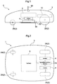
- Fig. 1 shows a side view of a work vehicle 1 managed by a management system 100 relating to this embodiment (see Fig. 3 ).
- Fig. 2 shows a plan view of the work vehicle 1.
- the work vehicle 1 includes wheels 2 and a vehicle body 3.
- the wheels 2 consist of first wheels 2A (an example of driving wheel unit) mounted on one end side in the longitudinal direction of the vehicle body and second wheels 2B mounted on the other end side in the longitudinal direction of the vehicle body.
- the first wheels 2A and the second wheels 2B are provided respectively one left and right pair along the width direction of the vehicle body.
- the first wheels 2A are provided as driving/steering wheels provided on the rear side in the advancing direction of the work vehicle 1 and driven by a traveling control device 10 which will be described later.
- the second wheels 2B are provided as so-called caster wheels provided on the front side in the advancing direction of the work vehicle 1. Accordingly, straight traveling is provided when the left and right wheels of the first wheels 2A are rotated at an equal speed in a same direction. When the left and right wheels of the first wheels 2A are rotated at different speeds in a same direction, steering is made to the slower side. Further, when the left and right wheels of the first wheels 2A are rotated at an equal speed but in different directions, the work vehicle 1 can spin at the present location.
- first wheels 2A and the second wheels 2B are provided respectively one left and right pair along the width direction of the vehicle body.
- this is only an example.
- the vehicle body 3 mounts thereon a pair of motors 4 as power source for the first wheels 2A, a battery 5 storing electric power to be supplied to the motors 4 and other electric devices included in the work vehicle 1, a traveling control device 10 for controlling traveling of the work vehicle 1, and a further motor 6 for driving a mower device 53 (an example of an "implement unit") having a cutter blade 54 for use in grass (lawn) cutting work.
- a mower device 53 an example of an "implement unit" having a cutter blade 54 for use in grass (lawn) cutting work.
- the vehicle body 3 mounts a GPS module 99 configured as a GNSS module.
- This GPS module 99 includes a GPS antenna for receiving GPS signals or GNSS signals (GPS signals in the instant embodiment).
- the GPS module 99 can include an inertial navigation module incorporating a gyro acceleration sensor, a geomagnetic direction sensor, etc. in order to assist the GPS navigation.
- the inertial navigation module can be provided at a site different from the GPS module 99. GPS signals acquired by the GPS module 99 will be utilized for the autonomous traveling of the work vehicle 1 described above or utilized as "GPS position information" by respective functional sections to be described later .
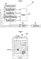
- Fig. 3 is a block diagram schematically showing an arrangement of the management system 100 of this embodiment.
- the management system 100 includes, as functional sections, a work field information acquisition section 21, a route information acquisition section 22, a consumed electric power information acquisition section 23, a tilt angle information acquisition section 24, a calculation section 25, a computation section 26, a traveling route storage section 27 and a compensation section 28.
- These respective functional sections are built as hardware and/or software using a CPU as the core component thereof in order to allow the work vehicle 1 to carry out a utility work continuously.
- the work field information acquisition section 21 acquires work field information indicative of information of a work field where a utility work is to be carried out.
- a work field where a utility work is to be carried out means a work field where a grass cutting work is to be carried out, in this embodiment.
- the information of the work field means position information indicative of the position (location) of the work field or information indicative of a position of an object (e.g. an obstacle) present within the work field.
- the information indicative of the position of the work field comprises position information represented by latitude/longitude using GPS and allows also grasping of a length of the work field in a predetermined direction and an area thereof based on the latitude/longitude of corners of the work field.
- Such work field information includes area information of the work field where the grass cutting work is to be carried out and information indicative of the position of an obstacle present in the work field.
- the work field information acquisition section 21 acquires such work field information and transmits this to the calculation section 25 which will be described later.
- the route information acquisition section 22 acquires route information indicative of a traveling route along which the work vehicle has traveled in the work field while carrying out the work therein.
- a traveling route along which the work vehicle has traveled in the work field while carrying out the work therein is a traveling route along which the work vehicle 1 has effected autonomous traveling while carrying out a grass cutting work.
- Such traveling route can be represented by latitudes and longitudes using the GPS.
- such traveling route can be specified by using both latitudes and longitudes using the GPS and information from the traveling control device 10.
- the route information includes traveling distance information indicative of a traveling distance over which the work vehicle 1 traveled during the work.
- the route information acquisition section 22 acquires such route information indicative of the actually traveled traveling route and/or traveling distance when the work vehicle 1 effected autonomous traveling while carrying out a grass cutting work.
- the route information acquired by the route information acquisition section 22 is transmitted to the calculation section 25 which will be described later.
- the consumed electric power information acquisition section 23 acquires electric power information indicative of electric power required for the work of an amount of electric power stored in the battery 3 mounted on the work vehicle 1.
- the battery 5 mounted on the work vehicle 1 is used, as described above, for traveling of the work vehicle 1 and driving of the mower device 53.
- the consumed electric power required for the work corresponds to the electric power consumed for traveling of the work vehicle 1 and driving of the mower device 53. Therefore, the consumed electric power information acquisition section 23 acquires such electric power information indicative of electric power required for the work of the amount of electric power stored in the battery 3 mounted on the work vehicle 1. This electric power information is transmitted to the calculation section 25 which will be described later.
- the tilt angle information acquisition section 24 acquires tilt angle information indicative of a tilt angle of the work field relative to the horizontal plane.
- a tilt angle of the work field relative to the horizontal plane means an angle formed by the horizontal plane and the work field where the grass cutting work is to be carried out. This tilt angle corresponds to a tilt angle of the vehicle body of the work vehicle 1.
- Such tilt angle can be detected by a known tilt angle sensor. And, such tilt angle information allows for specification of a degree of difficulty of the situation involving the grass cutting work carried out by the work vehicle 1.
- the tilt angle information acquired by the tilt angle information acquisition section 24 is transmitted to the calculation section 25 which will be described later.
- the calculation section 25 calculates a cost required for the work, based on the work field information, the route information, the electric power information and the tilt angle information.
- the work field information is transmitted from the work field information acquisition section 21.
- the route information is transmitted from the route information acquisition section 22.
- the electric power information is transmitted from the consumed electric power information acquisition section 23.
- the tilt angle information is transmitted from the tilt angle information acquisition section 24.
- the calculation section 25 calculates the cost required for the grass cutting work carried out by the work vehicle 1, with using the area of the work field where the grass cutting work was carried out based on the work field information, the traveling route along which the work vehicle traveled based on the route information, the consumed electric power used for the traveling of the work vehicle 1 and driving of the grass mower 53 based on the electric power information, and the difficulty degree of the situation in which the work vehicle 1 carried out the grass cutting work based on the tilt angle information.
- the calculation section 25 can effect the cost calculation with using not only the work field information including the area information and the route information including the traveling distance information, but also time information indicative of at least one of a work time required for the grass cutting work, a charging time for charging the battery 5 mounted on the work vehicle 1 and a moving time of the work vehicle 1.
- the management system 100 relating to this embodiment further includes a computation section 26 for computing a traveling route that allows cost reduction in the work to be carried out in the work field, based on the work field information, the route information, the electric power information and the tilt angle information.
- the work field information is transmitted from the work field information acquisition section 21.
- the route information is transmitted from the route information acquisition section 22.
- the electric power information is transmitted from the consumed electric power information acquisition section 23.
- the tilt angle information is transmitted from the tilt angle information acquisition section 24. Then, with using these information, the computation section 26 temporarily computes a traveling route optimal for the work field where the grass cutting work was once carried out. With this, for a traveling route along which the work cutting work was carried out with circumvention of an obstacle, a traveling route that allows reduction of the work cost can be readily derived.
- the traveling route computed by the computation section 26 will be transmitted to a traveling route storage section 27 to be stored therein.
- a work field where a grass cutting work is to be carried out can be set by an operation by a user on a map displayed on a display surface 201 of a terminal 200 carried/owned by this user.
- Fig. 4 shows the terminal 200.
- Such map displayed on the display surface 201 may use a map stored in the terminal 200 or may utilize map service provided via a network.
- a map including the work field where the cutting work is to be carried out is displayed on the display surface 201 and the work field and/or the obstacle is set by the user's operation on the display surface 201.
- information indicative of the position (latitude and longitude) of the work field set via using of the terminal 200 by the user will be forwarded to the traveling control device 10 and the work field information acquisition section 21. Then, the traveling control device 10 will carry out the grass cutting work based on the forwarded information indicating the positon of the work field. Also, the work field information acquisition section 21 will carry out the calculation of the cost based on the forwarded information indicating the positon of the work field.
- the information indicative of the position comprises position information represented by the latitude and longitude using the GPS, the information can contain a predetermined error. In such case as illustrated in Fig. 5 , there occurs a difference between the work field set with using the terminal 200 and the work field recognized by the management system 100. As a result, the work field where the grass cutting work is to be actually carried out will deviate from the intended work site.
- the management system 100 further includes a compensation section 28 for compensating position information indicative of the position of the work field set on the map displayed on the display surface 201 by position information indicative of the actual position of the work field.
- the position information indicative of the position of the work field set on the map displayed on the display surface 201 is position information using GPS as shown in Fig. 6 .
- the position information indicative of the actual position of the work field is actual position information.
- the compensation section 28 compensates the position information recognized by the management system 100 such that the GPS position information and the position indicative of the actual position of the work field may be brought into agreement with each other. More particularly, marks (denoted by ⁇ and ⁇ in Fig.
- the work field information includes area information indicative of the area of the work field and the route information includes traveling distance information indicative of the traveling distance traveled by the work vehicle 1 during the work.
- the work field information may be configured without including area information.
- the route information may be configured without including traveling distance information.
- the management system 100 includes the computation section 26 and the traveling route storage section 27.
- the management system 100 may omit both the computation section 26 and the traveling route storage section 27.
- the work field is set by a user's operation on a map displayed on the display surface 210 of the terminal 200 owned by the user.
- the work field can be set by using a map displayed on a display surface included in the management system 100, not on the display surface of the terminal 200 owned by the user.
- the work field can be set by using some other method as well.
- the management system 100 includes the compensation section 28.
- the management system 100 may be configured without such compensation section 28.
- the work is a grass (lawn) cutting work.
- the work maybe any other kind of work, instead.
- the present invention is applicable to a management system and a management method for a work vehicle configured to effect a utility work while traveling autonomously.
Landscapes
- Engineering & Computer Science (AREA)
- Business, Economics & Management (AREA)
- Remote Sensing (AREA)
- Radar, Positioning & Navigation (AREA)
- General Physics & Mathematics (AREA)
- Physics & Mathematics (AREA)
- Development Economics (AREA)
- Automation & Control Theory (AREA)
- Aviation & Aerospace Engineering (AREA)
- Accounting & Taxation (AREA)
- Finance (AREA)
- Strategic Management (AREA)
- Game Theory and Decision Science (AREA)
- Theoretical Computer Science (AREA)
- General Business, Economics & Management (AREA)
- Marketing (AREA)
- Economics (AREA)
- Entrepreneurship & Innovation (AREA)
- Life Sciences & Earth Sciences (AREA)
- Environmental Sciences (AREA)
- Guiding Agricultural Machines (AREA)
- Control Of Position, Course, Altitude, Or Attitude Of Moving Bodies (AREA)
- Harvester Elements (AREA)
- Management, Administration, Business Operations System, And Electronic Commerce (AREA)
Claims (10)
- Managementsystem (100) für ein Arbeitsfahrzeug, das dazu ausgestaltet ist, eine nützliche Arbeit auszuführen, während es autonom fährt, umfassend:eine Sektion (21) zur Erfassung von Arbeitsfeldinformationen zum Erfassen von Arbeitsfeldinformationen, die für Informationen in Verbindung mit einem Arbeitsfeld, wo die Arbeit ausgeführt werden soll, bezeichnend sind,eine Sektion (22) zur Erfassung von Routeninformationen zum Erfassen von Routeninformationen, die für eine Fahrtroute bezeichnend sind, entlang der das Fahrzeug gefahren ist, während es die Arbeit in dem Arbeitsfeld ausgeführt hat,eine Sektion (23) zur Erfassung von Informationen über verbrauchte elektrische Energie zum Erfassen von Informationen über elektrische Energie, die für die für die Arbeit benötigte verbrauchte elektrische Energie einer Menge an elektrischer Energie, die in einer an dem Arbeitsfahrzeug montierten Batterie (5) gespeichert ist, bezeichnend sind,dadurch gekennzeichnet, dass das System ferner umfasst:eine Sektion (24) zur Erfassung von Neigungswinkelinformationen zum Erfassen von Neigungswinkelinformationen, die für einen Neigungswinkel des Arbeitsfelds relativ zu der horizontalen Ebene bezeichnend sind, undeine Kalkulationssektion (25) zum Kalkulieren von Kosten, die für die Arbeit benötigt werden, auf Grundlage der Arbeitsfeldinformationen, der Routeninformationen, der Informationen über elektrische Energie und der Neigungswinkelinformationen.
- Managementsystem (100) nach Anspruch 1, wobei:die Arbeitsfeldinformationen Bereichsinformationen beinhalten, die für den Bereich des Arbeitsfelds bezeichnend sind, in dem die Arbeit ausgeführt werden soll,die Routeninformationen Fahrdistanzinformationen beinhalten, die für die Fahrdistanz, die das Arbeitsfahrzeug während der Arbeit zurückgelegt hat, bezeichnend sind,die Kalkulationssektion (25) die Kosten unter Verwendung von Zeitinformationen, die für zumindest eine aus der aus einer für die Arbeit erforderlichen Arbeitszeit, einer Aufladezeit für das Aufladen der an dem Fahrzeug montierten Batterie (5) und einer Bewegungszeit des Arbeitsfahrzeugs bestehenden Gruppe Ausgewählte bezeichnend sind, den Bereichsinformationen und den Fahrdistanzinformationen kalkuliert.
- Managementsystem (100) nach Anspruch 1 oder 2, ferner umfassend:eine Berechnungssektion (26) zur Berechnung einer Fahrtroute, die in der Lage ist, die Kosten der Arbeit, die in dem Arbeitsfeld ausgeführt werden soll, auf Grundlage der Arbeitsfeldinformationen, der Routeninformationen, der Informationen über elektrische Energie und der Neigungswinkelinformationen relativ zu einer Fahrtroute, die in dem Arbeitsfeld befahren wird, zu verringern,eine Fahrtrouten-Speichersektion (27) zum Speichern der Fahrtroute, die von der Berechnungssektion berechnet wurde.
- Managementsystem (100) nach einem der Ansprüche 1-3, wobei das Arbeitsfeld mittels Bedienung durch einen Benutzer auf einer Karte eingestellt wird, die auf einer Anzeigeoberfläche (201) eines Endgeräts (200), das dem Benutzer gehört, angezeigt wird.
- Managementsystem (100) nach Anspruch 4, ferner umfassend eine Kompensationssektion (28) zum Kompensieren von Positionsinformationen, die für eine Position eines Arbeitsfelds, das auf der Karte eingestellt ist, die auf der Anzeigeoberfläche (201) angezeigt wird, bezeichnend sind, mit Positionsinformationen, die für eine tatsächliche Position des Arbeitsfelds bezeichnend sind.
- Managementverfahren für ein Arbeitsfahrzeug (1), das dazu ausgestaltet ist, eine nützliche Arbeit auszuführen, während es autonom fährt, umfassend die Schritte des:Erfassens von Arbeitsfeldinformationen, die für Informationen in Verbindung mit einem Arbeitsfeld, wo die Arbeit ausgeführt werden soll, bezeichnend sind,Erfassens von Routeninformationen, die für eine Fahrtroute bezeichnend sind, entlang der das Fahrzeug gefahren ist, während es die Arbeit in dem Arbeitsfeld ausgeführt hat,Erfassens von Informationen über elektrische Energie, die für die für die Arbeit benötigte verbrauchte elektrische Energie einer Menge an elektrischer Energie, die in einer an dem Arbeitsfahrzeug montierten Batterie (5) gespeichert ist, bezeichnend sind,
gekennzeichnet durchErfassen von Neigungswinkelinformationen, die für einen Neigungswinkel des Arbeitsfelds relativ zu der horizontalen Ebene bezeichnend sind, undKalkulieren von Kosten, die für die Arbeit benötigt werden, auf Grundlage der Arbeitsfeldinformationen, der Routeninformationen, der Informationen über elektrische Energie und der Neigungswinkelinformationen. - Managementverfahren nach Anspruch 6, wobei:die Arbeitsfeldinformationen Bereichsinformationen beinhalten, die für den Bereich des Arbeitsfelds, in dem die Arbeit ausgeführt werden soll, bezeichnend sind,die Routeninformationen Fahrdistanzinformationen beinhalten, die für die Fahrdistanz, die das Arbeitsfahrzeug während der Arbeit zurückgelegt hat, bezeichnend sinddie Kalkulationssektion die Kosten unter Verwendung von Zeitinformationen, die für zumindest eine aus der aus einer für die Arbeit erforderlichen Arbeitszeit, einer Aufladezeit für das Aufladen der an dem Fahrzeug montierten Batterie und einer Bewegungszeit des Arbeitsfahrzeugs bestehenden Gruppe Ausgewählte bezeichnend sind, den Bereichsinformationen und den Fahrdistanzinformationen kalkuliert.
- Managementverfahren nach Anspruch 6 oder 7, ferner umfassend die Schritte des:Berechnens einer Fahrtroute, die in der Lage ist, die Kosten der Arbeit, die in dem Arbeitsfeld ausgeführt werden soll, auf Grundlage der Arbeitsfeldinformationen, der Routeninformationen, der Informationen über elektrische Energie und der Neigungswinkelinformationen relativ zu einer Fahrtroute, die in dem Arbeitsfeld befahren wird, zu verringern, undSpeicherns der berechneten Fahrtroute.
- Managementverfahren nach einem der Ansprüche 6-8, wobei das Arbeitsfeld mittels Bedienung durch einen Benutzer auf einer Karte eingestellt wird, die auf einer Anzeigeoberfläche (201) eines Endgeräts (200), das dem Benutzer gehört, angezeigt wird.
- Managementverfahren nach Anspruch 9, ferner umfassend den Schritt des Kompensierens von Positionsinformationen, die für eine Position eines Arbeitsfelds bezeichnend sind, das auf der Karte, die auf der Anzeigeoberfläche angezeigt wird, eingestellt ist, mit Positionsinformationen, die für eine tatsächliche Position des Arbeitsfelds bezeichnend sind.
Applications Claiming Priority (1)
| Application Number | Priority Date | Filing Date | Title |
|---|---|---|---|
| JP2017233298A JP7072376B2 (ja) | 2017-12-05 | 2017-12-05 | 管理システム |
Publications (2)
| Publication Number | Publication Date |
|---|---|
| EP3495909A1 EP3495909A1 (de) | 2019-06-12 |
| EP3495909B1 true EP3495909B1 (de) | 2020-11-11 |
Family
ID=64023928
Family Applications (1)
| Application Number | Title | Priority Date | Filing Date |
|---|---|---|---|
| EP18199650.5A Active EP3495909B1 (de) | 2017-12-05 | 2018-10-10 | Verwaltungssystem und verwaltungsverfahren für ein arbeitsfahrzeug |
Country Status (3)
| Country | Link |
|---|---|
| US (1) | US11199844B2 (de) |
| EP (1) | EP3495909B1 (de) |
| JP (1) | JP7072376B2 (de) |
Families Citing this family (2)
| Publication number | Priority date | Publication date | Assignee | Title |
|---|---|---|---|---|
| JP7476035B2 (ja) * | 2020-08-28 | 2024-04-30 | 株式会社やまびこ | 作業ロボットの制御装置及び制御方法 |
| CN116976642B (zh) * | 2023-08-31 | 2024-04-02 | 宁夏绿昊光伏发电有限公司 | 一种电力通信智慧机房运维管理系统及其方法 |
Family Cites Families (23)
| Publication number | Priority date | Publication date | Assignee | Title |
|---|---|---|---|---|
| JP3643946B2 (ja) * | 1998-04-21 | 2005-04-27 | 株式会社クボタ | 情報端末装置、農作業機及び記録媒体 |
| SE0100924D0 (sv) | 2001-03-15 | 2001-03-15 | Electrolux Ab | Energy-efficient navigation of an autonomous surface treatment apparatus |
| JP2004098233A (ja) | 2002-09-10 | 2004-04-02 | Matsushita Electric Ind Co Ltd | 自律移動ロボット |
| US6728607B1 (en) | 2002-10-03 | 2004-04-27 | Deere & Company | Method and system for determining an energy-efficient path of a machine |
| KR100745975B1 (ko) | 2004-12-30 | 2007-08-06 | 삼성전자주식회사 | 그리드 맵을 사용하여 최소 이동 경로로 이동하는 방법 및장치 |
| US9615501B2 (en) * | 2007-01-18 | 2017-04-11 | Deere & Company | Controlling the position of an agricultural implement coupled to an agricultural vehicle based upon three-dimensional topography data |
| US8565984B2 (en) * | 2007-03-16 | 2013-10-22 | Deere & Comany | System and method of steering for a work vehicle towing a towed implement on lateral slopes |
| US8626441B2 (en) * | 2008-06-17 | 2014-01-07 | Agco Corporation | Methods and apparatus for using position/attitude information to enhance a vehicle guidance system |
| JP5332034B2 (ja) | 2008-09-22 | 2013-11-06 | 株式会社小松製作所 | 無人車両の走行経路生成方法 |
| JP5453769B2 (ja) * | 2008-11-06 | 2014-03-26 | トヨタ自動車株式会社 | 車両用電池診断システムおよび車両用電池診断方法 |
| JP2010159113A (ja) | 2009-01-07 | 2010-07-22 | Hino Motors Ltd | エネルギー消費量算出装置、エネルギー消費量算出方法およびプログラム |
| NL1037476C2 (nl) | 2009-11-17 | 2011-05-18 | Lely Patent Nv | Autonoom verrijdbaar landbouwvoertuig. |
| US8612273B2 (en) * | 2010-04-01 | 2013-12-17 | The Crawford Group, Inc. | Method and system for managing vehicle travel |
| JP2012105557A (ja) | 2010-11-15 | 2012-06-07 | Original Soft:Kk | 自動芝刈り機 |
| JP5859870B2 (ja) | 2012-02-10 | 2016-02-16 | 本田技研工業株式会社 | 無人走行作業車の誘導装置 |
| JP6240384B2 (ja) | 2012-11-29 | 2017-11-29 | ヤンマー株式会社 | 自律走行作業システム |
| JP6059027B2 (ja) * | 2013-01-21 | 2017-01-11 | 株式会社クボタ | 農作業機と農作業管理プログラム |
| JP2015191608A (ja) | 2014-03-28 | 2015-11-02 | ヤンマー株式会社 | 作業情報管理システム |
| JP2016028311A (ja) | 2014-07-10 | 2016-02-25 | 株式会社リコー | ロボット、プログラム、及び記憶媒体 |
| KR102698059B1 (ko) * | 2016-03-09 | 2024-08-22 | 얀마 파워 테크놀로지 가부시키가이샤 | 작업 차량 및 주행 영역 특정 장치 |
| JP6212591B2 (ja) | 2016-03-31 | 2017-10-11 | 本田技研工業株式会社 | 自律走行作業車の制御装置 |
| US11129323B2 (en) * | 2016-09-29 | 2021-09-28 | Agro Intelligence Aps | System and a method for optimizing the trajectory to be followed when weeding crops |
| US11672201B2 (en) * | 2017-08-16 | 2023-06-13 | Briggs & Stratton, Llc | Modular mower deck for use with a lawnmower |
-
2017
- 2017-12-05 JP JP2017233298A patent/JP7072376B2/ja active Active
-
2018
- 2018-10-09 US US16/154,769 patent/US11199844B2/en active Active
- 2018-10-10 EP EP18199650.5A patent/EP3495909B1/de active Active
Non-Patent Citations (1)
| Title |
|---|
| None * |
Also Published As
| Publication number | Publication date |
|---|---|
| JP7072376B2 (ja) | 2022-05-20 |
| EP3495909A1 (de) | 2019-06-12 |
| US11199844B2 (en) | 2021-12-14 |
| US20190171216A1 (en) | 2019-06-06 |
| JP2019097505A (ja) | 2019-06-24 |
Similar Documents
| Publication | Publication Date | Title |
|---|---|---|
| US11675352B2 (en) | Travel route determination system | |
| JP7479425B2 (ja) | 走行作業機 | |
| EP3722903A1 (de) | Vorrichtung zur einstellung der reiseroute | |
| JP6975668B2 (ja) | 作業車両用の自動走行システム | |
| WO2020129704A1 (ja) | 走行作業機 | |
| JP7036707B2 (ja) | 走行経路生成装置 | |
| EP3498070A1 (de) | Nutzfahrzeug | |
| WO2020129722A1 (ja) | 自動走行作業車のための制御装置 | |
| JP2017061264A (ja) | 車両の操舵制御装置 | |
| KR20190077060A (ko) | 경로 생성 시스템 | |
| EP3495909B1 (de) | Verwaltungssystem und verwaltungsverfahren für ein arbeitsfahrzeug | |
| KR102420670B1 (ko) | 작업 차량용 안테나 유닛, 및 작업 차량 | |
| Park et al. | A real-time high-speed autonomous driving based on a low-cost RTK-GPS | |
| JP2020101964A (ja) | 走行状態表示装置、及び、自動走行システム | |
| JP7045979B2 (ja) | 走行作業機 | |
| JP7146675B2 (ja) | 自動走行システム | |
| JP7094833B2 (ja) | 走行経路表示装置 | |
| JP6945353B2 (ja) | 自動走行作業車 | |
| JP7122956B2 (ja) | 走行作業機 | |
| JP7223087B2 (ja) | 走行経路特定方法 | |
| JP2023063476A (ja) | 作業車両用の自動走行システム | |
| JP2020030644A (ja) | 自動走行システム | |
| JP2022075733A (ja) | 作業支援システム |
Legal Events
| Date | Code | Title | Description |
|---|---|---|---|
| PUAI | Public reference made under article 153(3) epc to a published international application that has entered the european phase |
Free format text: ORIGINAL CODE: 0009012 |
|
| STAA | Information on the status of an ep patent application or granted ep patent |
Free format text: STATUS: REQUEST FOR EXAMINATION WAS MADE |
|
| 17P | Request for examination filed |
Effective date: 20181010 |
|
| AK | Designated contracting states |
Kind code of ref document: A1 Designated state(s): AL AT BE BG CH CY CZ DE DK EE ES FI FR GB GR HR HU IE IS IT LI LT LU LV MC MK MT NL NO PL PT RO RS SE SI SK SM TR |
|
| AX | Request for extension of the european patent |
Extension state: BA ME |
|
| GRAP | Despatch of communication of intention to grant a patent |
Free format text: ORIGINAL CODE: EPIDOSNIGR1 |
|
| STAA | Information on the status of an ep patent application or granted ep patent |
Free format text: STATUS: GRANT OF PATENT IS INTENDED |
|
| INTG | Intention to grant announced |
Effective date: 20200604 |
|
| GRAS | Grant fee paid |
Free format text: ORIGINAL CODE: EPIDOSNIGR3 |
|
| GRAA | (expected) grant |
Free format text: ORIGINAL CODE: 0009210 |
|
| STAA | Information on the status of an ep patent application or granted ep patent |
Free format text: STATUS: THE PATENT HAS BEEN GRANTED |
|
| AK | Designated contracting states |
Kind code of ref document: B1 Designated state(s): AL AT BE BG CH CY CZ DE DK EE ES FI FR GB GR HR HU IE IS IT LI LT LU LV MC MK MT NL NO PL PT RO RS SE SI SK SM TR |
|
| REG | Reference to a national code |
Ref country code: GB Ref legal event code: FG4D |
|
| REG | Reference to a national code |
Ref country code: CH Ref legal event code: EP |
|
| REG | Reference to a national code |
Ref country code: AT Ref legal event code: REF Ref document number: 1334100 Country of ref document: AT Kind code of ref document: T Effective date: 20201115 |
|
| REG | Reference to a national code |
Ref country code: DE Ref legal event code: R096 Ref document number: 602018009602 Country of ref document: DE |
|
| REG | Reference to a national code |
Ref country code: IE Ref legal event code: FG4D |
|
| REG | Reference to a national code |
Ref country code: NL Ref legal event code: MP Effective date: 20201111 |
|
| REG | Reference to a national code |
Ref country code: AT Ref legal event code: MK05 Ref document number: 1334100 Country of ref document: AT Kind code of ref document: T Effective date: 20201111 |
|
| PG25 | Lapsed in a contracting state [announced via postgrant information from national office to epo] |
Ref country code: RS Free format text: LAPSE BECAUSE OF FAILURE TO SUBMIT A TRANSLATION OF THE DESCRIPTION OR TO PAY THE FEE WITHIN THE PRESCRIBED TIME-LIMIT Effective date: 20201111 Ref country code: PT Free format text: LAPSE BECAUSE OF FAILURE TO SUBMIT A TRANSLATION OF THE DESCRIPTION OR TO PAY THE FEE WITHIN THE PRESCRIBED TIME-LIMIT Effective date: 20210311 Ref country code: FI Free format text: LAPSE BECAUSE OF FAILURE TO SUBMIT A TRANSLATION OF THE DESCRIPTION OR TO PAY THE FEE WITHIN THE PRESCRIBED TIME-LIMIT Effective date: 20201111 Ref country code: NO Free format text: LAPSE BECAUSE OF FAILURE TO SUBMIT A TRANSLATION OF THE DESCRIPTION OR TO PAY THE FEE WITHIN THE PRESCRIBED TIME-LIMIT Effective date: 20210211 Ref country code: GR Free format text: LAPSE BECAUSE OF FAILURE TO SUBMIT A TRANSLATION OF THE DESCRIPTION OR TO PAY THE FEE WITHIN THE PRESCRIBED TIME-LIMIT Effective date: 20210212 |
|
| PG25 | Lapsed in a contracting state [announced via postgrant information from national office to epo] |
Ref country code: AT Free format text: LAPSE BECAUSE OF FAILURE TO SUBMIT A TRANSLATION OF THE DESCRIPTION OR TO PAY THE FEE WITHIN THE PRESCRIBED TIME-LIMIT Effective date: 20201111 Ref country code: BG Free format text: LAPSE BECAUSE OF FAILURE TO SUBMIT A TRANSLATION OF THE DESCRIPTION OR TO PAY THE FEE WITHIN THE PRESCRIBED TIME-LIMIT Effective date: 20210211 Ref country code: PL Free format text: LAPSE BECAUSE OF FAILURE TO SUBMIT A TRANSLATION OF THE DESCRIPTION OR TO PAY THE FEE WITHIN THE PRESCRIBED TIME-LIMIT Effective date: 20201111 Ref country code: LV Free format text: LAPSE BECAUSE OF FAILURE TO SUBMIT A TRANSLATION OF THE DESCRIPTION OR TO PAY THE FEE WITHIN THE PRESCRIBED TIME-LIMIT Effective date: 20201111 Ref country code: IS Free format text: LAPSE BECAUSE OF FAILURE TO SUBMIT A TRANSLATION OF THE DESCRIPTION OR TO PAY THE FEE WITHIN THE PRESCRIBED TIME-LIMIT Effective date: 20210311 Ref country code: SE Free format text: LAPSE BECAUSE OF FAILURE TO SUBMIT A TRANSLATION OF THE DESCRIPTION OR TO PAY THE FEE WITHIN THE PRESCRIBED TIME-LIMIT Effective date: 20201111 |
|
| REG | Reference to a national code |
Ref country code: LT Ref legal event code: MG9D |
|
| PG25 | Lapsed in a contracting state [announced via postgrant information from national office to epo] |
Ref country code: HR Free format text: LAPSE BECAUSE OF FAILURE TO SUBMIT A TRANSLATION OF THE DESCRIPTION OR TO PAY THE FEE WITHIN THE PRESCRIBED TIME-LIMIT Effective date: 20201111 |
|
| PG25 | Lapsed in a contracting state [announced via postgrant information from national office to epo] |
Ref country code: SM Free format text: LAPSE BECAUSE OF FAILURE TO SUBMIT A TRANSLATION OF THE DESCRIPTION OR TO PAY THE FEE WITHIN THE PRESCRIBED TIME-LIMIT Effective date: 20201111 Ref country code: CZ Free format text: LAPSE BECAUSE OF FAILURE TO SUBMIT A TRANSLATION OF THE DESCRIPTION OR TO PAY THE FEE WITHIN THE PRESCRIBED TIME-LIMIT Effective date: 20201111 Ref country code: EE Free format text: LAPSE BECAUSE OF FAILURE TO SUBMIT A TRANSLATION OF THE DESCRIPTION OR TO PAY THE FEE WITHIN THE PRESCRIBED TIME-LIMIT Effective date: 20201111 Ref country code: LT Free format text: LAPSE BECAUSE OF FAILURE TO SUBMIT A TRANSLATION OF THE DESCRIPTION OR TO PAY THE FEE WITHIN THE PRESCRIBED TIME-LIMIT Effective date: 20201111 Ref country code: SK Free format text: LAPSE BECAUSE OF FAILURE TO SUBMIT A TRANSLATION OF THE DESCRIPTION OR TO PAY THE FEE WITHIN THE PRESCRIBED TIME-LIMIT Effective date: 20201111 Ref country code: RO Free format text: LAPSE BECAUSE OF FAILURE TO SUBMIT A TRANSLATION OF THE DESCRIPTION OR TO PAY THE FEE WITHIN THE PRESCRIBED TIME-LIMIT Effective date: 20201111 |
|
| REG | Reference to a national code |
Ref country code: DE Ref legal event code: R097 Ref document number: 602018009602 Country of ref document: DE |
|
| PG25 | Lapsed in a contracting state [announced via postgrant information from national office to epo] |
Ref country code: DK Free format text: LAPSE BECAUSE OF FAILURE TO SUBMIT A TRANSLATION OF THE DESCRIPTION OR TO PAY THE FEE WITHIN THE PRESCRIBED TIME-LIMIT Effective date: 20201111 |
|
| PLBE | No opposition filed within time limit |
Free format text: ORIGINAL CODE: 0009261 |
|
| STAA | Information on the status of an ep patent application or granted ep patent |
Free format text: STATUS: NO OPPOSITION FILED WITHIN TIME LIMIT |
|
| 26N | No opposition filed |
Effective date: 20210812 |
|
| PG25 | Lapsed in a contracting state [announced via postgrant information from national office to epo] |
Ref country code: IT Free format text: LAPSE BECAUSE OF FAILURE TO SUBMIT A TRANSLATION OF THE DESCRIPTION OR TO PAY THE FEE WITHIN THE PRESCRIBED TIME-LIMIT Effective date: 20201111 Ref country code: NL Free format text: LAPSE BECAUSE OF FAILURE TO SUBMIT A TRANSLATION OF THE DESCRIPTION OR TO PAY THE FEE WITHIN THE PRESCRIBED TIME-LIMIT Effective date: 20201111 Ref country code: AL Free format text: LAPSE BECAUSE OF FAILURE TO SUBMIT A TRANSLATION OF THE DESCRIPTION OR TO PAY THE FEE WITHIN THE PRESCRIBED TIME-LIMIT Effective date: 20201111 |
|
| PG25 | Lapsed in a contracting state [announced via postgrant information from national office to epo] |
Ref country code: SI Free format text: LAPSE BECAUSE OF FAILURE TO SUBMIT A TRANSLATION OF THE DESCRIPTION OR TO PAY THE FEE WITHIN THE PRESCRIBED TIME-LIMIT Effective date: 20201111 |
|
| PG25 | Lapsed in a contracting state [announced via postgrant information from national office to epo] |
Ref country code: ES Free format text: LAPSE BECAUSE OF FAILURE TO SUBMIT A TRANSLATION OF THE DESCRIPTION OR TO PAY THE FEE WITHIN THE PRESCRIBED TIME-LIMIT Effective date: 20201111 |
|
| REG | Reference to a national code |
Ref country code: DE Ref legal event code: R119 Ref document number: 602018009602 Country of ref document: DE |
|
| REG | Reference to a national code |
Ref country code: CH Ref legal event code: PL |
|
| PG25 | Lapsed in a contracting state [announced via postgrant information from national office to epo] |
Ref country code: IS Free format text: LAPSE BECAUSE OF FAILURE TO SUBMIT A TRANSLATION OF THE DESCRIPTION OR TO PAY THE FEE WITHIN THE PRESCRIBED TIME-LIMIT Effective date: 20210311 |
|
| REG | Reference to a national code |
Ref country code: BE Ref legal event code: MM Effective date: 20211031 |
|
| PG25 | Lapsed in a contracting state [announced via postgrant information from national office to epo] |
Ref country code: MC Free format text: LAPSE BECAUSE OF FAILURE TO SUBMIT A TRANSLATION OF THE DESCRIPTION OR TO PAY THE FEE WITHIN THE PRESCRIBED TIME-LIMIT Effective date: 20201111 |
|
| PG25 | Lapsed in a contracting state [announced via postgrant information from national office to epo] |
Ref country code: LU Free format text: LAPSE BECAUSE OF NON-PAYMENT OF DUE FEES Effective date: 20211010 Ref country code: DE Free format text: LAPSE BECAUSE OF NON-PAYMENT OF DUE FEES Effective date: 20220503 Ref country code: BE Free format text: LAPSE BECAUSE OF NON-PAYMENT OF DUE FEES Effective date: 20211031 |
|
| PG25 | Lapsed in a contracting state [announced via postgrant information from national office to epo] |
Ref country code: LI Free format text: LAPSE BECAUSE OF NON-PAYMENT OF DUE FEES Effective date: 20211031 Ref country code: CH Free format text: LAPSE BECAUSE OF NON-PAYMENT OF DUE FEES Effective date: 20211031 |
|
| PG25 | Lapsed in a contracting state [announced via postgrant information from national office to epo] |
Ref country code: IE Free format text: LAPSE BECAUSE OF NON-PAYMENT OF DUE FEES Effective date: 20211010 |
|
| GBPC | Gb: european patent ceased through non-payment of renewal fee |
Effective date: 20221010 |
|
| PG25 | Lapsed in a contracting state [announced via postgrant information from national office to epo] |
Ref country code: CY Free format text: LAPSE BECAUSE OF FAILURE TO SUBMIT A TRANSLATION OF THE DESCRIPTION OR TO PAY THE FEE WITHIN THE PRESCRIBED TIME-LIMIT Effective date: 20201111 |
|
| PG25 | Lapsed in a contracting state [announced via postgrant information from national office to epo] |
Ref country code: HU Free format text: LAPSE BECAUSE OF FAILURE TO SUBMIT A TRANSLATION OF THE DESCRIPTION OR TO PAY THE FEE WITHIN THE PRESCRIBED TIME-LIMIT; INVALID AB INITIO Effective date: 20181010 |
|
| PG25 | Lapsed in a contracting state [announced via postgrant information from national office to epo] |
Ref country code: GB Free format text: LAPSE BECAUSE OF NON-PAYMENT OF DUE FEES Effective date: 20221010 |
|
| PG25 | Lapsed in a contracting state [announced via postgrant information from national office to epo] |
Ref country code: MK Free format text: LAPSE BECAUSE OF FAILURE TO SUBMIT A TRANSLATION OF THE DESCRIPTION OR TO PAY THE FEE WITHIN THE PRESCRIBED TIME-LIMIT Effective date: 20201111 |
|
| PG25 | Lapsed in a contracting state [announced via postgrant information from national office to epo] |
Ref country code: TR Free format text: LAPSE BECAUSE OF FAILURE TO SUBMIT A TRANSLATION OF THE DESCRIPTION OR TO PAY THE FEE WITHIN THE PRESCRIBED TIME-LIMIT Effective date: 20201111 |
|
| PG25 | Lapsed in a contracting state [announced via postgrant information from national office to epo] |
Ref country code: MT Free format text: LAPSE BECAUSE OF FAILURE TO SUBMIT A TRANSLATION OF THE DESCRIPTION OR TO PAY THE FEE WITHIN THE PRESCRIBED TIME-LIMIT Effective date: 20201111 |
|
| PGFP | Annual fee paid to national office [announced via postgrant information from national office to epo] |
Ref country code: FR Payment date: 20250908 Year of fee payment: 8 |