EP3495233B1 - System zur drahtlosen zugsteuerung und verfahren zur drahtlosen zugsteuerung - Google Patents
System zur drahtlosen zugsteuerung und verfahren zur drahtlosen zugsteuerung Download PDFInfo
- Publication number
- EP3495233B1 EP3495233B1 EP16911624.1A EP16911624A EP3495233B1 EP 3495233 B1 EP3495233 B1 EP 3495233B1 EP 16911624 A EP16911624 A EP 16911624A EP 3495233 B1 EP3495233 B1 EP 3495233B1
- Authority
- EP
- European Patent Office
- Prior art keywords
- train
- track
- radio
- vehicle control
- ground base
- Prior art date
- Legal status (The legal status is an assumption and is not a legal conclusion. Google has not performed a legal analysis and makes no representation as to the accuracy of the status listed.)
- Active
Links
Images



Classifications
-
- B—PERFORMING OPERATIONS; TRANSPORTING
- B61—RAILWAYS
- B61L—GUIDING RAILWAY TRAFFIC; ENSURING THE SAFETY OF RAILWAY TRAFFIC
- B61L27/00—Central railway traffic control systems; Trackside control; Communication systems specially adapted therefor
- B61L27/20—Trackside control of safe travel of vehicle or train, e.g. braking curve calculation
-
- B—PERFORMING OPERATIONS; TRANSPORTING
- B60—VEHICLES IN GENERAL
- B60L—PROPULSION OF ELECTRICALLY-PROPELLED VEHICLES; SUPPLYING ELECTRIC POWER FOR AUXILIARY EQUIPMENT OF ELECTRICALLY-PROPELLED VEHICLES; ELECTRODYNAMIC BRAKE SYSTEMS FOR VEHICLES IN GENERAL; MAGNETIC SUSPENSION OR LEVITATION FOR VEHICLES; MONITORING OPERATING VARIABLES OF ELECTRICALLY-PROPELLED VEHICLES; ELECTRIC SAFETY DEVICES FOR ELECTRICALLY-PROPELLED VEHICLES
- B60L15/00—Methods, circuits, or devices for controlling the traction-motor speed of electrically-propelled vehicles
- B60L15/40—Adaptation of control equipment on vehicle for remote actuation from a stationary place
-
- B—PERFORMING OPERATIONS; TRANSPORTING
- B61—RAILWAYS
- B61L—GUIDING RAILWAY TRAFFIC; ENSURING THE SAFETY OF RAILWAY TRAFFIC
- B61L1/00—Devices along the route controlled by interaction with the vehicle or train
- B61L1/18—Railway track circuits
-
- B—PERFORMING OPERATIONS; TRANSPORTING
- B61—RAILWAYS
- B61L—GUIDING RAILWAY TRAFFIC; ENSURING THE SAFETY OF RAILWAY TRAFFIC
- B61L23/00—Control, warning or like safety means along the route or between vehicles or trains
- B61L23/08—Control, warning or like safety means along the route or between vehicles or trains for controlling traffic in one direction only
- B61L23/14—Control, warning or like safety means along the route or between vehicles or trains for controlling traffic in one direction only automatically operated
-
- B—PERFORMING OPERATIONS; TRANSPORTING
- B61—RAILWAYS
- B61L—GUIDING RAILWAY TRAFFIC; ENSURING THE SAFETY OF RAILWAY TRAFFIC
- B61L27/00—Central railway traffic control systems; Trackside control; Communication systems specially adapted therefor
- B61L27/10—Operations, e.g. scheduling or time tables
- B61L27/16—Trackside optimisation of vehicle or train operation
-
- B—PERFORMING OPERATIONS; TRANSPORTING
- B61—RAILWAYS
- B61L—GUIDING RAILWAY TRAFFIC; ENSURING THE SAFETY OF RAILWAY TRAFFIC
- B61L27/00—Central railway traffic control systems; Trackside control; Communication systems specially adapted therefor
- B61L27/30—Trackside multiple control systems, e.g. switch-over between different systems
- B61L27/33—Backup systems, e.g. switching when failures occur
-
- B—PERFORMING OPERATIONS; TRANSPORTING
- B61—RAILWAYS
- B61L—GUIDING RAILWAY TRAFFIC; ENSURING THE SAFETY OF RAILWAY TRAFFIC
- B61L27/00—Central railway traffic control systems; Trackside control; Communication systems specially adapted therefor
- B61L27/40—Handling position reports or trackside vehicle data
-
- B—PERFORMING OPERATIONS; TRANSPORTING
- B61—RAILWAYS
- B61L—GUIDING RAILWAY TRAFFIC; ENSURING THE SAFETY OF RAILWAY TRAFFIC
- B61L27/00—Central railway traffic control systems; Trackside control; Communication systems specially adapted therefor
- B61L27/70—Details of trackside communication
-
- B—PERFORMING OPERATIONS; TRANSPORTING
- B60—VEHICLES IN GENERAL
- B60L—PROPULSION OF ELECTRICALLY-PROPELLED VEHICLES; SUPPLYING ELECTRIC POWER FOR AUXILIARY EQUIPMENT OF ELECTRICALLY-PROPELLED VEHICLES; ELECTRODYNAMIC BRAKE SYSTEMS FOR VEHICLES IN GENERAL; MAGNETIC SUSPENSION OR LEVITATION FOR VEHICLES; MONITORING OPERATING VARIABLES OF ELECTRICALLY-PROPELLED VEHICLES; ELECTRIC SAFETY DEVICES FOR ELECTRICALLY-PROPELLED VEHICLES
- B60L2200/00—Type of vehicles
- B60L2200/26—Rail vehicles
-
- B—PERFORMING OPERATIONS; TRANSPORTING
- B61—RAILWAYS
- B61L—GUIDING RAILWAY TRAFFIC; ENSURING THE SAFETY OF RAILWAY TRAFFIC
- B61L27/00—Central railway traffic control systems; Trackside control; Communication systems specially adapted therefor
- B61L27/20—Trackside control of safe travel of vehicle or train, e.g. braking curve calculation
- B61L2027/204—Trackside control of safe travel of vehicle or train, e.g. braking curve calculation using Communication-based Train Control [CBTC]
Definitions
- the present invention relates to a radio train control system and a radio train control method.
- a radio train control system called communication based train control (CBTC) controls train traffic through communication between a radio-control adaptive train and a ground base device that is a control device on the ground.
- CBTC communication based train control
- a ground base device fails to operate properly, such a radio train control system cannot obtain the positions of trains in an area controlled by the ground base device.
- Japanese Patent Application Laid-open No. 2007-15517 serving as the prior art teaches a technique aiming at "providing a train control system capable of reliably controlling trains on tracks in an area covered by a base device that controls trains even when the base device has gone down", which can realize control of trains on tracks based on additional provision of an ID detection device connected to an on-track vehicle control device without interposition of a base device.
- Document WO 2012/155835 A1 shows a CTCS (China train control system)-3 train operation control system comprises a ground equipment and an on-board equipment.
- the ground equipment comprises a section control system, a wireless blocking center and a ground wireless communication module, wherein the section control system is used for acquiring and sending track occupancy information and route state information, the wireless blocking center is used for generating train operation permission information and receiving train operation data, and the ground wireless communication module is used for generating ground wireless data and sending the train operation data to the wireless blocking center.
- the on-board equipment comprises an on-board wireless communication module and a safety control module, wherein the on-board wireless communication module is used for receiving the train operation permission information, generating train wireless data and sending the data in a wireless way, and the safety control module is used for controlling train operation according to the train operation permission information and sending train data.
- the on-board wireless communication module is used for receiving the train operation permission information, generating train wireless data and sending the data in a wireless way
- the safety control module is used for controlling train operation according to the train operation permission information and sending train data.
- Document EP 2 039 583 A1 shows a train control system establishing radio communication between a plurality of on-train radio control apparatuses moving on a predetermined path and a plurality of ground train radio control units disposed along a predetermined path, so as to establish parallel simultaneous radio communications on a plurality of radio communication channels of various communication frequencies between the plurality of on-train radio communication apparatuses and the plurality of ground train radio control units, wherein one radio communication channel is selected out of the plurality of radio communication channels to perform an authentication request and an authentication process, wherein an encryption key obtained by the authentication process is used as a common encryption key shared by the plurality of on-train radio control units to encrypt data communication between the plurality of on-train radio control units and the plurality of ground train radio control units.
- the present invention has been made in view of the above circumstances, and an object thereof is to provide a radio train control system capable of suppressing the increase in facility cost and reliably controlling trains on tracks even when a ground base device is out of order.
- the present invention provides a radio train control system that controls a train on a track on which a track circuit is built, the radio train control system comprising: a ground radio device to perform radio communication with the trains and acquire position information of the train; a field device to acquire track circuit state information indicating whether the track circuit is ON or OFF; a ground base device to receive the position information and the track circuit state information and transmit control information to the train; and an on-track vehicle control device to manage on-track information with receiving the position information and the track circuit state information, wherein the ground radio device and the field device have a transmission path connected with the on-track vehicle control device without using the ground base device, and the on-track vehicle control device, when the ground base device is out of order, is capable of transmitting the control information to the train through the transmission path and performing operation as the ground base device, and the ground radio device, when the ground base device is out of order, wirelessly transmits train control information transmitted from the on ⁇ track vehicle control device to the train and transmits the
- the present invention produces an advantageous effect of making it possible to provide a radio train control system capable of suppressing the increase in facility cost and reliably controlling trains on tracks even when a ground base device is out of order.
- FIG. 1 is a diagram illustrating an example configuration of a radio train control system 8 according to a first embodiment of the present invention.
- the radio train control system 8 illustrated in FIG. 1 includes an on-track vehicle control device 1 including a track database storage unit 2, ground base devices 3A and 3B, ground radio devices 4A and 4B, field devices 5A and 5B, trains 6A and 6B, and relays 7A, 7B, 7C, 7D, 7E, 7F, and 7G.
- the trains 6A and 6B travel on tracks on which track circuits are built.
- the ground base device 3A is deemed to be out of order when communication with the ground base device 3A is disabled, and the ground base device 3B is deemed to be out of order when communication with the ground base device 3B is disabled. More specifically, the ground base devices 3A and 3B each transmit on-track information of trains in the control area to the on-track vehicle control device 1 at a constant frequency, for example, and the on-track vehicle control device 1 recognizes that the ground base device 3A or 3B is out of order when the on-track information to be transmitted ceases.
- the on-track information includes at least either of train position information or track circuit state information, which will be described later.
- the track circuit state information is information indicating whether a track circuit is ON or OFF.
- the on-track vehicle control device 1 manages the on-track information acquired from the ground base devices 3A and 3B, and is capable of transmitting train control information to the trains 6A and 6B as substituted for the ground base devices 3A and 3B when the ground base devices 3A and 3B are out of order.
- the track database storage unit 2 stores a track database of an area controlled by the on-track vehicle control device 1.
- the track database will be described later.
- the ground base devices 3A and 3B communicate with the trains 6A and 6B via the ground radio devices 4A and 4B to receive train information including the position information of the trains 6A and 6B, receive track circuit state information from the field devices 5A and 5B, and transmit train control information to the trains 6A and 6B.
- the ground radio devices 4A and 4B perform radio communication with the trains 6A and 6B to wirelessly transmit the train control information transmitted from the ground base devices 3A and 3B to the trains 6A and 6B, acquire train information including the train position information received from the trains 6A and 6B and transmit the acquired train information to the ground base devices 3A and 3B.
- the ground radio devices 4A and 4B wirelessly transmit the train control information transmitted from the on-track vehicle control device 1 to the trains 6A and 6B, and transmit the train information including the train position information received from the trains 6A and 6B to the on-track vehicle control device 1.
- the field devices 5A and 5B acquire track circuit state information and point machine state information outputted from the relays 7A, 7B, 7C, 7D, 7E, 7F, and 7G, and transmit the acquired information to the ground base devices 3A and 3B.
- the field devices 5A and 5B transmit the track circuit state information and the point machine state information to the on-track vehicle control device 1 through transmission paths connected to the field devices 5A and 5B without intervention of the ground base devices 3A and 3B.
- the track circuit state information indicates OFF when a train is present on a track circuit
- the track circuit state information indicates ON when a train is not present on the track circuit.
- the point machine state information is information indicating directions and lock states of point machines.
- Each of the trains 6A and 6B controlled by the radio train control system 8 includes an on-board control device, which is not illustrated, and an on-board radio device, which is not illustrated.
- the not-illustrated on-board radio devices perform radio communication with the ground radio devices 4A and 4B, and information acquired by the not-illustrated on-board radio devices through radio communication is acquired by the not-illustrated on-board control devices.
- the not-illustrated on-board control devices control the trains 6A and 6B.
- Each of the relays 7A, 7B, 7C, 7D, 7E, 7F, and 7G outputs track circuit state information indicating whether or not a train is present on corresponding one of the track circuits represented by A to G in FIG. 1 to the field devices 5A and 5B.
- the radio train control system 8 illustrated in FIG. 1 includes transmission paths through which the on-track vehicle control device 1 is connected with the ground radio devices 4A and 4B and the field devices 5A and 5B without intervention of the ground base devices 3A and 3B, and the on-track vehicle control device 1 can act as a ground base device in place of the ground base devices 3A and 3B.
- the on-track vehicle control device 1 is connected with the ground radio devices 4A and 4B and the field devices 5A and 5B through the transmission paths for connection without intervention of the ground base devices 3A and 3B, and then the on-track vehicle control device 1 is thus capable of operating the radio train control system 8 even when the ground base devices 3A and 3B are out of order by performing operation as a ground base device in place of the ground base devices 3A and 3B.
- the transmission of information from the ground radio devices 4A and 4B and the field devices 5A and 5B to the on-track vehicle control device 1 may also be performed while the ground base devices 3A and 3B normally operate, or may be performed only when the ground base devices 3A and 3B are out of order.
- the on-track vehicle control device 1 can acquire on-track information of trains in the control area from track circuit state information acquired from the field device 5A through the transmission paths connected without using the ground base device 3A.
- the radio train control system 8 is capable of continuing to operate even when the ground base devices 3A and 3B are out of order since the on-track vehicle control device 1 performs operation as a ground base device when the ground base devices 3A and 3B are out of order. Next, the operation while the ground base devices 3A and 3B are out of order will be described.
- FIG. 2 is a diagram illustrating a control area of a ground base device that is out of order, and on-track states of trains in the area.
- the ground base devices adjacent to both sides of the control area of the ground base device that is out of order are not out of order but operate normally.
- the on-track vehicle control device 1 is capable of acquiring the on-track information of the trains also in the area of the ground base device that is out of order from the ground radio device and the field device through the transmission paths connected without using the ground base devices 3A and 3B.
- the on-track vehicle control device 1 acquires the on-track information of trains, the track circuit state information, and the point machine state information in the area of the ground base device that is out of order, and evacuates all the train(s) present in the area to the adjacent areas.
- a train 1 and a train 3 can perform their evacuation operation since no other train is present between the trains 1 and 3 and corresponding one of controlled areas of the adjacent ground base devices.
- a train 2 cannot perform its evacuation operation until the evacuation operation of the train 1 is completed since the train 1 is present between the train 2 and the adjacent area.
- the train 2 starts the evacuation operation after the evacuation operation of the train 1 is completed.
- FIG. 3 is a diagram for explaining a method of expressing positions and paths in the first embodiment.
- FIG. 3 illustrates blocks [B1001], [B1002], [B1003], [B1004], and [B1005].
- the block [B1001] is connected with the block [B1002]
- the block [B1002] is connected with the blocks [B1003] and [B1005]
- the block [B1003] is connected with the block [B1004].
- a path R1001 is a path from the block [B1001] to the block [B1002]
- a path R1002 is a path from the block [B1002] to the block [B1005]
- a path R1003 is a path from the block [B1002] to the block [B1004].
- a track circuit T1 is a track circuit of the block [B1001]
- a track circuit T2 is a track circuit of the blocks [B1002], [B1003], [B1004],
- a block has a beginning and a termination, and a position in the block is expressed by a distance from the beginning or the termination.
- FIG. 4 is a diagram illustrating an example of the track database stored in the track database storage unit 2.
- FIG. 4 connected blocks through which trains can travel are defined.
- a block connected to the up side of the block [B1001] is not illustrated and is represented by three dots, and no point machine is connected with the bock [B1001].
- no data is present for the block connected to the up side and the point machine condition, and [B1002] is indicated for the block connected to the down side.
- the block [B1002] is connected with the block [B1001] on the up side, with the blocks [B1003] and [B1005] on the down side, and with a point machine 10.
- N representing "Normal” is written in the database when the direction of the point machine 10 is a normal direction
- R representing "Reverse” is written in the database when the direction of the point machine 10 is a reverse direction
- the direction for the block [B1005] is the normal direction
- the direction for the block [B1003] is the reverse direction in FIG. 4 .
- [B1002] is indicated as the block connected to the up side
- [B1003] and [B1005] are indicated as blocks connected to the down side
- "10:R” is indicated as the point machine condition for [B1003] of the blocks connected to the down side
- “10:N” is indicated as the point machine condition for [B1005] of the blocks connected to the down side.
- the block [B1003] is connected with the block [B1002] on the up side, with the block [B1004] on the down side, and with the point machine 10 in the reverse direction.
- [B1003] [B1002] is indicated as the block connected to the up side
- [B1004] is indicated as the block connected to the down side
- "10:R" is indicated as the point machine condition for [B1004] that is the block connected to the down side.
- a block connected to the down side of the block [B1004] is not illustrated and is represented by three dots, and no point machine is connected with the block [B1004].
- no data is present for the block connected to the down side and the point machine condition, and [B1003] is indicated as the block connected to the up side.
- the block [B1005] is connected with the block [B1002] on the up side, a block connected to the down side of the block [B1005] is not illustrated and is represented by three dots, and the block [B1005] is connected with the point machine 10 in the normal direction.
- no data is present for the block connected to the down side
- [B1002] is indicated as the block connected to the up side
- "10:N" is indicated as the point machine condition for [B1002] that is the block connected to the up side.
- FIG. 5 is a diagram illustrating an example of on-track information of trains, track circuit state information, and point machine state information.
- the on-track information of trains illustrated in FIG. 5 indicates a front position and a rear position of a train.
- the front position of the train is indicated as being at a position of 100 meters from the beginning of the block [B1001] and the rear position of the train is indicated as being at a position of 40 meters from the beginning of the block [B1001].
- the track circuit state information of trains illustrated in FIG. 5 indicates whether the states of the track circuits T1, T2, and T3 are ON or OFF.
- the state of the track circuit T1 is OFF, and the states of the track circuits T2 and T3 are ON.
- the point machine state information illustrated in FIG. 5 indicates the direction and the lock state of each point machine.
- the direction of the point machine 10 is indicated as being normal, and the lock state of the point machine 10 is indicated as being locked.
- FIG. 6 is a flowchart illustrating an example operation of the on-track vehicle control device 1 when the ground base device 3A is out of order.
- the on-track vehicle control device 1 starts processing by selecting a train 6A, selects the traveling direction of the train 6A and an on-track block in which the front position of the train 6A is present from the track database stored in the track database storage unit 2 (S11), and performs a subroutine process for acquiring block or blocks connected to the block that is currently selected (S12).
- the block that is currently selected is an on-track block in which the front position of the train 6A is present.
- the subroutine for acquiring the connected blocks will be described later with reference to FIG. 7 .
- the on-track vehicle control device 1 determines whether or not an acquired connected block is present as a result of the subroutine of S12 (S13).
- the on-track vehicle control device 1 determines that evacuation cannot be performed (S18), and ends the processing. If a connected block acquired in S12 is present (S13: Yes), the on-track vehicle control device 1 performs a subroutine process for determining whether or not an on-track train is present (S14). The on-track vehicle control device 1 then determines whether or not another on-track train is present from the result of S14 (S15). Note that the subroutine of S14 for determining whether or not an on-track train is present will be described later with reference to FIG. 8 .
- the on-track vehicle control device 1 determines that evacuation cannot be performed (S18), and ends the processing. If no other on-track train is present as a result of S14 (S15: No), the on-track vehicle control device 1 determines whether or not the currently selected block has reached an area where a ground base device is currently operating in a normal way (S16).
- the on-track vehicle control device 1 determines that evacuation can be performed (S17), and ends the processing. If the selected block has not reached an area where a ground base device is currently operating in a normal way (S16: No), the on-track vehicle control device 1 advances the selected block in the traveling direction (S19), and returns to S12. Note that, if it is determined that evacuation can be performed, the train 6A is operated to be evacuated to the area where the ground base device is currently operating in a normal way. Such an evacuation operation may be performed automatically, or by the train driver with the determination result being displayed on a driver's console.
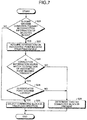
- FIG. 7 is a flowchart illustrating details of the subroutine process of S12.
- the on-track vehicle control device 1 determines whether or not a point machine condition is present in connection information of the selected block (S21). If no point machine condition is present in the connection information of the selected block (S21: No), the number of blocks that can be selected is one, and so the on-track vehicle control device 1 selects a connected block in the traveling direction (S26), and ends the subroutine process.
- the on-track vehicle control device 1 acquires information on the point machine in question (S22), and determines whether or not connection information that has a match to the direction of the point machine is present (S23). Note that the information on the point machine includes the direction and the lock state of the point machine, which are acquired from a field device. If no connection information that has a match to the direction of the point machine is present (S23: No), the direction of the point machine is assumed to be unknown, and the on-track vehicle control device 1 determines that no connected block is present (S25), and ends the subroutine process.
- connection information that has a match to the direction of the point machine is present (S23: Yes)
- the on-track vehicle control device 1 determines whether or not the point machine has been locked (S24). If the point machine has not been locked (S24: No), the on-track vehicle control device 1 determines that no connected block is present (S25), and ends the subroutine process. If the point machine has been locked (S24: Yes), the on-track vehicle control device 1 selects a connected block in the traveling direction (S26), and ends the subroutine process.
- FIG. 8 is a flowchart illustrating details of the subroutine process of S14.
- the on-track vehicle control device 1 determines whether or not on-track information of another train whose front position or rear position is in the selected block is present (S31). If on-track information of another train whose front position or rear position is in the selected block is present (S31: Yes), the on-track vehicle control device 1 determines that another on-track train is present (S37), and ends the subroutine process. If no on-track information of another train whose front position or rear position is in the selected block is present (S31: No), the on-track vehicle control device 1 determines whether or not a track circuit associated with the selected block is present (S32).
- the on-track vehicle control device 1 determines that no other on-track train is present (S36), and ends the subroutine process. If a track circuit associated with the selected block is present (S32: Yes), the on-track vehicle control device 1 determines whether or not the track circuit is identical to the track circuit associated with a block where the front position of the selected train is present (S33). If the track circuit is identical to the track circuit associated with the front position block of the selected train (S33: Yes), the on-track vehicle control device 1 determines that no other on-track train is present (S36), and ends the processing.
- the on-track vehicle control device 1 acquires track circuit state information of the selected block (S34), and determines whether or not the track circuit is ON (S35). If the track circuit is not ON (S35: No), the on-track vehicle control device 1 determines that another on-track train is present (S37), and ends the subroutine process. If the track circuit is ON (S35: Yes), the on-track vehicle control device 1 determines that no other on-track train is present (S36), and ends the subroutine process.
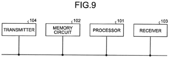
- the on-track vehicle control device 1 includes a processor, a memory circuit, a receiver, and a transmitter, and their respective operations can be implemented by software.
- FIG. 9 is a diagram illustrating a typical example configuration of hardware implementing the on-track vehicle control device 1 in the first embodiment.
- the device illustrated in FIG. 9 includes a processor 101, a memory circuit 102, a receiver 103, and a transmitter 104, in which the processor 101 performs computation and control by software using received data, and the memory 102 stores received data or data and software necessary for the processor 101 to perform computation and control.
- the receiver 103 is an interface that receives information from outside.
- the transmitter 104 is an interface that transmits information to outside.
- no device for train detection connected with the on-track vehicle control device is needed, and a radio train control system capable of suppressing the increase in facility cost and reliably performing on-track control of trains even when a ground base device is out of order is achieved.
- on-track vehicle control can be performed in dependence upon the states of track circuits when a control device mounted on a train is out of order.
- evacuation operation of a train from an area where a ground base device has been out of order can be performed even in the state in which the ground base device is out of order.
- the radio train control system can be resumed at an early point without waiting for recovery of the ground base device by making a train shuttle back and forth in areas adjacent to the area where the ground base device has been out of order.
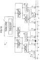
- FIG. 10 is a diagram illustrating an example configuration of a radio train control system 8a according to the second embodiment of the present invention.
- the radio train control system 8a illustrated in FIG. 10 has the same configuration as the radio train control system 8 illustrated in FIG. 1 except that an interlocking device 9 and a point machine 10 are added to the system 8.
- the point machine 10 is provided in a track circuit represented by C.
- the interlocking device 9 is a device that is provided between the on-track vehicle control device 1 and the ground radio devices 4A and 4B, and is capable of controlling the direction of the point machine 10 on the track. In a case where the direction of the point machine 10 is unknown, the interlocking device 9 can control the direction of the point machine 10 according to an instruction from the on-track vehicle control device 1 so that a train on the track can perform evacuation operation. Alternatively, in a case where a train that cannot be evacuated because of the direction of the point machine 10 is present, the interlocking device 9 can control the direction of the point machine 10 according to an instruction from the on-track vehicle control device 1 so that the evacuation operation can be performed.
- evacuation operation of a train on the track is enabled regardless of the direction of a point machine when a ground base device is out of order.
- 1 on-track vehicle control device 1 on-track vehicle control device; 2 track database storage unit; 3A, 3B ground base device; 4A, 4B ground radio device; 5A, 5B field device; 6A, 6B train; 7A, 7B, 7C, 7D, 7E, 7F, 7G relay; 8, 8a radio train control system; 9 interlocking device; 10 point machine; 101 processor; 102 memory circuit; 103 receiver; 104 transmitter.
Landscapes
- Engineering & Computer Science (AREA)
- Mechanical Engineering (AREA)
- Automation & Control Theory (AREA)
- Power Engineering (AREA)
- Transportation (AREA)
- Train Traffic Observation, Control, And Security (AREA)
Claims (5)
- Funkzugsteuerungssystem (8), das einen Zug (6A, 6B) auf einem Gleis steuert, auf dem ein Gleisschaltkreis gebaut ist, wobei das Funkzugsteuerungssystem (8) aufweist:eine Bodenfunkeinrichtung (4A, 4B) zum Durchführen von Funkkommunikation mit den Zügen (6A, 6B) und Erlangen von Positionsinformation des Zugs (6A, 6B);eine Feldeinrichtung (5A, 5B) zum Erlangen von Gleisschaltkreiszustandsinformation, die angibt, ob der Gleisschaltkreis AN oder AUS ist;eine Bodenbasiseinrichtung (3A, 3B) zum Empfangen der Positionsinformation und der Gleisschaltkreiszustandsinformation und Übertragen von Steuerungsinformation zu dem Zug (6A, 6B); undeine Auf-Gleis-Fahrzeugsteuerungseinrichtung (1) zum Managen von Auf-Gleis-Information, die mindestens entweder die Positionsinformation oder die Gleisschaltkreisinformation aufweist, wobeidie Funkeinrichtung (4A, 4B) und die Feldeinrichtung (5A, 5B) einen Übertragungspfad aufweisen, der mit der Auf-Gleis-Fahrzeugsteuerungseinrichtung (1) verbunden ist, ohne die Bodenbasiseinrichtung (3A, 3B) zu nutzen,die Auf-Gleis-Fahrzeugsteuerungseinrichtung (1), wenn die Bodenbasiseinrichtung (3A, 3B) außer Betrieb ist, dazu in der Lage ist, die Steuerungsinformation zu dem Zug (6A, 6B) durch den Übertragungspfad zu übertragen und einen Betrieb als die Bodenbasiseinrichtung (3A, 3B) durchzuführen, unddie Bodenbasiseinrichtung (4A, 4B), wenn die Bodenbasiseinrichtung (3A, 3B) außer Betrieb ist, drahtlos Zugsteuerungsinformation, die von der Auf-Gleis-Fahrzeugsteuerungseinrichtung (1) übertragen ist, zu dem Zug (6A, 6B) überträgt und Positionsinformation, die von dem Zug (6A, 6B) empfangen ist, zu der Auf-Gleis-Fahrzeugsteuerungseinrichtung (1) überträgt.
- Funkzugsteuerungssystem (8) nach Anspruch 1, wobei die Auf-Gleis-Fahrzeugsteuerungseinrichtung (1) die Gleisschaltkreiszustandsinformation durch den Übertragungspfad empfängt, wenn die Bodenfunkeinrichtung (4A, 4B) außer Betrieb ist.
- Funkzugsteuerungssystem (8) nach Anspruch 1, wobei, wenn die Bodenbasiseinrichtung (3A, 3B) außer Betrieb ist, die Auf-Gleis-Steuerungseinrichtung (1) sich auf die Auf-Gleis-Information bezieht und den Zug (6A, 6B) zu einem Steuerungsbereich einer weiteren Bodenbasiseinrichtung (3A, 3B) evakuiert, die normal arbeitet.
- Funkzugsteuerungssystem (8a) nach Anspruch 1, des Weiteren mit einer Verschlusseinrichtung (9), die zwischen der Auf-Gleis-Fahrzeugsteuerungseinrichtung (1) und der Bodenfunkeinrichtung (4A, 4B) bereitgestellt ist und dazu in der Lage ist, einen Weichenantrieb (10) des Gleises zu steuern.
- Funkzugsteuerungsverfahren zum Betreiben des Funkzugsteuerungssystems nach einem der Ansprüche 1 bis 4 zum Steuern der Auf-Gleis-Fahrzeugsteuerungseinrichtung (1) zum Durchführen eines Evakuierungsvorgangs des Evakuierens eines Zugs (6A, 6B) aus einem Steuerungsbereich, der durch die Bodenbasiseinrichtung (3A, 3B) gesteuert ist, wenn die Bodenbasiseinrichtung (3A, 3B) außer Betrieb ist, wobei das Funkzugsteuerungsverfahren aufweist:einen Schritt des Auswählens, durch die Auf-Gleis-Fahrzeugsteuerungseinrichtung (1), eines Auf-Gleis-Blocks, in dem eine Vorderposition des Zugs (6A, 6B) vorhanden ist;einen Schritt des Erlangens, durch die Auf-Gleis-Fahrzeugsteuerungseinrichtung (1) eines verbundenen Blocks, der mit dem Auf-Gleis-Block verbunden ist, wobei der verbundene Block in einer Fahrtrichtung des Zugs (6A, 6B) vorhanden ist;einen Schritt des Bestimmens, durch die Auf-Gleis-Fahrzeugsteuerungseinrichtung (1), dass ein Evakuierungsbetrieb des Zugs (6A, 6B) nicht durchgeführt werden kann, wenn kein verbundener Block, der mit dem Auf-Gleis-Block verbunden ist, vorhanden ist und kein verbundener Block erlangt wird;einen Schritt des Bestimmens, durch die Auf-Gleis-Fahrzeugsteuerungseinrichtung (1), ob oder nicht ein weiterer Zug (6A, 6B) in dem Steuerungsbereich der Bodenbasiseinrichtung (3A, 3B) vorhanden ist;einen Schritt des Bestimmens, durch die Auf-Gleis-Fahrzeugsteuerungseinrichtung (1), dass ein Evakuierungsbetrieb des Zugs (6A, 6B) nicht durchgeführt werden kann, wenn ein weiterer Zug (6A, 6B) in dem Steuerungsbereich vorhanden ist;einen Schritt des Bestimmens, dass eine Evakuierung durchgeführt werden kann, wenn der Zug (6A, 6B) in einem Steuerungsbereich einer Bodenbasiseinrichtung (3A, 3B) vorhanden ist, die normal arbeitet; undeinen Schritt des Vorwärtsbewegens einer Auswahl eines Auf-Gleis-Blocks um einen Block in einer Fahrtrichtung, wenn der Zug (6A, 6B) nicht in einem Steuerungsbereich einer Bodenbasiseinrichtung (3A, 3B) vorhanden ist, die normal arbeitet.
Applications Claiming Priority (1)
| Application Number | Priority Date | Filing Date | Title |
|---|---|---|---|
| PCT/JP2016/072908 WO2018025365A1 (ja) | 2016-08-04 | 2016-08-04 | 無線列車制御システム及び無線列車制御方法 |
Publications (3)
| Publication Number | Publication Date |
|---|---|
| EP3495233A1 EP3495233A1 (de) | 2019-06-12 |
| EP3495233A4 EP3495233A4 (de) | 2019-11-06 |
| EP3495233B1 true EP3495233B1 (de) | 2021-11-03 |
Family
ID=61073000
Family Applications (1)
| Application Number | Title | Priority Date | Filing Date |
|---|---|---|---|
| EP16911624.1A Active EP3495233B1 (de) | 2016-08-04 | 2016-08-04 | System zur drahtlosen zugsteuerung und verfahren zur drahtlosen zugsteuerung |
Country Status (4)
| Country | Link |
|---|---|
| US (1) | US11117601B2 (de) |
| EP (1) | EP3495233B1 (de) |
| JP (1) | JP6532609B2 (de) |
| WO (1) | WO2018025365A1 (de) |
Families Citing this family (3)
| Publication number | Priority date | Publication date | Assignee | Title |
|---|---|---|---|---|
| EP3842318A1 (de) * | 2019-12-23 | 2021-06-30 | Thales Management & Services Deutschland GmbH | Verfahren zur datenübertragung innerhalb eines schienengebundenen verkehrssystems, datenübertragungssystem, schienengebundenes verkehrssystem mit einem datenübertragungssystem und verwendung von kommunikationseinheiten an feldelementen |
| CN112706805B (zh) * | 2021-03-26 | 2021-09-10 | 交控科技股份有限公司 | 轨旁设备、轨道星链系统及列车运行控制系统 |
| ES2959096B2 (es) * | 2022-07-22 | 2024-11-11 | Redislogar S A | Estructura de gabinete para puestos fijos en un sistema transmisor de comunicación tren-tierra con sistema de gestión para monitorizar y operar remotamente |
Family Cites Families (16)
| Publication number | Priority date | Publication date | Assignee | Title |
|---|---|---|---|---|
| US5420883A (en) * | 1993-05-17 | 1995-05-30 | Hughes Aircraft Company | Train location and control using spread spectrum radio communications |
| JP4301888B2 (ja) * | 2003-08-27 | 2009-07-22 | 日本信号株式会社 | 列車制御装置 |
| JP4454303B2 (ja) * | 2003-12-22 | 2010-04-21 | 株式会社日立製作所 | 信号保安システム |
| JP4931377B2 (ja) * | 2005-07-06 | 2012-05-16 | 東日本旅客鉄道株式会社 | 列車管理システム |
| GB2430528A (en) * | 2005-09-22 | 2007-03-28 | Westinghouse Brake & Signal | Transmitting movement authorities to trains independently of the interlocking controlling lineside signals. |
| JP4471996B2 (ja) * | 2007-09-18 | 2010-06-02 | 株式会社日立製作所 | 列車制御システム |
| JP4999752B2 (ja) * | 2008-03-28 | 2012-08-15 | 公益財団法人鉄道総合技術研究所 | 無線基地局停止時における列車間隔制御 |
| US8989926B2 (en) * | 2009-11-18 | 2015-03-24 | Convergent Communications, Inc. | Railroad signaling and communication system using a fail-safe voltage sensor to verify trackside conditions in safety-critical railroad applications |
| JP5415391B2 (ja) | 2010-11-04 | 2014-02-12 | 公益財団法人鉄道総合技術研究所 | 無線列車制御システム及び無線列車制御方法 |
| CN102238231B (zh) * | 2011-05-16 | 2013-12-18 | 铁道部运输局 | Ctcs-3级无线闭塞中心设备及系统 |
| CN102233887A (zh) | 2011-05-16 | 2011-11-09 | 铁道部运输局 | Ctcs-3级列车运行控制系统 |
| JP5922902B2 (ja) * | 2011-09-30 | 2016-05-24 | 日本信号株式会社 | 無線通信ネットワークシステムの同期方法 |
| JP5877538B2 (ja) * | 2011-09-30 | 2016-03-08 | 日本信号株式会社 | 列車制御システム |
| KR101318850B1 (ko) | 2012-01-04 | 2013-10-17 | 현대로템 주식회사 | 무선통신시스템과 폴백시스템을 이용한 열차제어시스템 및 방법 |
| WO2014064826A1 (ja) * | 2012-10-26 | 2014-05-01 | 株式会社京三製作所 | 在線検知装置及び在線検知方法 |
| JP5885654B2 (ja) * | 2012-12-28 | 2016-03-15 | 株式会社東芝 | 列車制御システム |
-
2016
- 2016-08-04 JP JP2018531046A patent/JP6532609B2/ja active Active
- 2016-08-04 WO PCT/JP2016/072908 patent/WO2018025365A1/ja not_active Ceased
- 2016-08-04 US US16/318,438 patent/US11117601B2/en not_active Expired - Fee Related
- 2016-08-04 EP EP16911624.1A patent/EP3495233B1/de active Active
Non-Patent Citations (1)
| Title |
|---|
| None * |
Also Published As
| Publication number | Publication date |
|---|---|
| US11117601B2 (en) | 2021-09-14 |
| EP3495233A1 (de) | 2019-06-12 |
| JPWO2018025365A1 (ja) | 2018-11-15 |
| EP3495233A4 (de) | 2019-11-06 |
| WO2018025365A1 (ja) | 2018-02-08 |
| US20190291758A1 (en) | 2019-09-26 |
| JP6532609B2 (ja) | 2019-06-19 |
Similar Documents
| Publication | Publication Date | Title |
|---|---|---|
| EP2039583B1 (de) | Bahnfunksteuersystem | |
| US8985524B2 (en) | On-board device for train control system | |
| JP5201880B2 (ja) | 無線制御方法及び無線制御システム | |
| KR20180132966A (ko) | 열차 제어 시스템 | |
| KR101852048B1 (ko) | 궤도차량용 통신시스템 | |
| JPWO2018109830A1 (ja) | 列車制御システム、地上制御装置および車上制御装置 | |
| CN110366518A (zh) | Ad-hoc通信网络 | |
| EP3495233A1 (de) | System zur drahtlosen zugsteuerung und verfahren zur drahtlosen zugsteuerung | |
| KR101339348B1 (ko) | 궤도회로를 이용한 이동폐색과 고정폐색의 혼합 운행 시스템 및 방법 | |
| JP4934542B2 (ja) | 無線による列車制御システム及び無線列車制御方法 | |
| CN103179131A (zh) | 列车控制的通信方法、装置及系统 | |
| KR101289725B1 (ko) | 모노레일에서의 무선 송수신 시스템 및 그 제어 방법, 그리고 모노레일에서의 무선 송수신 시스템 데이터 처리 방법 | |
| JP6270504B2 (ja) | 列車無線システム | |
| KR101349167B1 (ko) | 선로 곡선부의 효율적인 광대역 무선 데이터 전송을 위한 전후방 양방향 무선송수신 방법 | |
| US20040111722A1 (en) | Remote control system for locomotives using a networking arrangement | |
| JPH11261473A (ja) | 情報送受信装置および方法、情報送受信システム、並びに記録媒体 | |
| KR102287253B1 (ko) | 인접 열차 간 직접 통신의 오류 발생 시 통신 절체 기술 | |
| JP2020090236A (ja) | 列車位置検出装置及び列車位置検出システム | |
| JP5551145B2 (ja) | 無線制御方法及び無線制御システム | |
| KR101029796B1 (ko) | 열차의 송신채널 제어를 통한 무선 통신 시스템 | |
| JP2004120347A (ja) | 列車通信システム | |
| JP3926713B2 (ja) | 列車通信システム及び中継処理装置 | |
| KR102322903B1 (ko) | 열차 운행을 위한 비면허 통신과 승객 서비스용 비면허 통신간 간섭 완화를 위한 연동 기법 | |
| KR101271622B1 (ko) | 무선 제어장치 및 무선 제어 방법 | |
| JP2655083B2 (ja) | 送信出力制御方式 |
Legal Events
| Date | Code | Title | Description |
|---|---|---|---|
| STAA | Information on the status of an ep patent application or granted ep patent |
Free format text: STATUS: THE INTERNATIONAL PUBLICATION HAS BEEN MADE |
|
| PUAI | Public reference made under article 153(3) epc to a published international application that has entered the european phase |
Free format text: ORIGINAL CODE: 0009012 |
|
| STAA | Information on the status of an ep patent application or granted ep patent |
Free format text: STATUS: REQUEST FOR EXAMINATION WAS MADE |
|
| 17P | Request for examination filed |
Effective date: 20190129 |
|
| AK | Designated contracting states |
Kind code of ref document: A1 Designated state(s): AL AT BE BG CH CY CZ DE DK EE ES FI FR GB GR HR HU IE IS IT LI LT LU LV MC MK MT NL NO PL PT RO RS SE SI SK SM TR |
|
| AX | Request for extension of the european patent |
Extension state: BA ME |
|
| A4 | Supplementary search report drawn up and despatched |
Effective date: 20191004 |
|
| RIC1 | Information provided on ipc code assigned before grant |
Ipc: B61L 27/00 20060101ALI20190927BHEP Ipc: B61L 1/18 20060101ALI20190927BHEP Ipc: B61L 23/14 20060101AFI20190927BHEP |
|
| DAV | Request for validation of the european patent (deleted) | ||
| DAX | Request for extension of the european patent (deleted) | ||
| GRAP | Despatch of communication of intention to grant a patent |
Free format text: ORIGINAL CODE: EPIDOSNIGR1 |
|
| STAA | Information on the status of an ep patent application or granted ep patent |
Free format text: STATUS: GRANT OF PATENT IS INTENDED |
|
| INTG | Intention to grant announced |
Effective date: 20201023 |
|
| GRAJ | Information related to disapproval of communication of intention to grant by the applicant or resumption of examination proceedings by the epo deleted |
Free format text: ORIGINAL CODE: EPIDOSDIGR1 |
|
| STAA | Information on the status of an ep patent application or granted ep patent |
Free format text: STATUS: REQUEST FOR EXAMINATION WAS MADE |
|
| INTC | Intention to grant announced (deleted) | ||
| GRAP | Despatch of communication of intention to grant a patent |
Free format text: ORIGINAL CODE: EPIDOSNIGR1 |
|
| STAA | Information on the status of an ep patent application or granted ep patent |
Free format text: STATUS: GRANT OF PATENT IS INTENDED |
|
| INTG | Intention to grant announced |
Effective date: 20210517 |
|
| GRAS | Grant fee paid |
Free format text: ORIGINAL CODE: EPIDOSNIGR3 |
|
| GRAA | (expected) grant |
Free format text: ORIGINAL CODE: 0009210 |
|
| STAA | Information on the status of an ep patent application or granted ep patent |
Free format text: STATUS: THE PATENT HAS BEEN GRANTED |
|
| AK | Designated contracting states |
Kind code of ref document: B1 Designated state(s): AL AT BE BG CH CY CZ DE DK EE ES FI FR GB GR HR HU IE IS IT LI LT LU LV MC MK MT NL NO PL PT RO RS SE SI SK SM TR |
|
| REG | Reference to a national code |
Ref country code: GB Ref legal event code: FG4D |
|
| REG | Reference to a national code |
Ref country code: AT Ref legal event code: REF Ref document number: 1443716 Country of ref document: AT Kind code of ref document: T Effective date: 20211115 Ref country code: CH Ref legal event code: EP |
|
| REG | Reference to a national code |
Ref country code: DE Ref legal event code: R096 Ref document number: 602016065883 Country of ref document: DE |
|
| REG | Reference to a national code |
Ref country code: IE Ref legal event code: FG4D |
|
| REG | Reference to a national code |
Ref country code: LT Ref legal event code: MG9D |
|
| REG | Reference to a national code |
Ref country code: NL Ref legal event code: MP Effective date: 20211103 |
|
| REG | Reference to a national code |
Ref country code: AT Ref legal event code: MK05 Ref document number: 1443716 Country of ref document: AT Kind code of ref document: T Effective date: 20211103 |
|
| PG25 | Lapsed in a contracting state [announced via postgrant information from national office to epo] |
Ref country code: RS Free format text: LAPSE BECAUSE OF FAILURE TO SUBMIT A TRANSLATION OF THE DESCRIPTION OR TO PAY THE FEE WITHIN THE PRESCRIBED TIME-LIMIT Effective date: 20211103 Ref country code: LT Free format text: LAPSE BECAUSE OF FAILURE TO SUBMIT A TRANSLATION OF THE DESCRIPTION OR TO PAY THE FEE WITHIN THE PRESCRIBED TIME-LIMIT Effective date: 20211103 Ref country code: FI Free format text: LAPSE BECAUSE OF FAILURE TO SUBMIT A TRANSLATION OF THE DESCRIPTION OR TO PAY THE FEE WITHIN THE PRESCRIBED TIME-LIMIT Effective date: 20211103 Ref country code: BG Free format text: LAPSE BECAUSE OF FAILURE TO SUBMIT A TRANSLATION OF THE DESCRIPTION OR TO PAY THE FEE WITHIN THE PRESCRIBED TIME-LIMIT Effective date: 20220203 Ref country code: AT Free format text: LAPSE BECAUSE OF FAILURE TO SUBMIT A TRANSLATION OF THE DESCRIPTION OR TO PAY THE FEE WITHIN THE PRESCRIBED TIME-LIMIT Effective date: 20211103 |
|
| PG25 | Lapsed in a contracting state [announced via postgrant information from national office to epo] |
Ref country code: IS Free format text: LAPSE BECAUSE OF FAILURE TO SUBMIT A TRANSLATION OF THE DESCRIPTION OR TO PAY THE FEE WITHIN THE PRESCRIBED TIME-LIMIT Effective date: 20220303 Ref country code: SE Free format text: LAPSE BECAUSE OF FAILURE TO SUBMIT A TRANSLATION OF THE DESCRIPTION OR TO PAY THE FEE WITHIN THE PRESCRIBED TIME-LIMIT Effective date: 20211103 Ref country code: PT Free format text: LAPSE BECAUSE OF FAILURE TO SUBMIT A TRANSLATION OF THE DESCRIPTION OR TO PAY THE FEE WITHIN THE PRESCRIBED TIME-LIMIT Effective date: 20220303 Ref country code: PL Free format text: LAPSE BECAUSE OF FAILURE TO SUBMIT A TRANSLATION OF THE DESCRIPTION OR TO PAY THE FEE WITHIN THE PRESCRIBED TIME-LIMIT Effective date: 20211103 Ref country code: NO Free format text: LAPSE BECAUSE OF FAILURE TO SUBMIT A TRANSLATION OF THE DESCRIPTION OR TO PAY THE FEE WITHIN THE PRESCRIBED TIME-LIMIT Effective date: 20220203 Ref country code: NL Free format text: LAPSE BECAUSE OF FAILURE TO SUBMIT A TRANSLATION OF THE DESCRIPTION OR TO PAY THE FEE WITHIN THE PRESCRIBED TIME-LIMIT Effective date: 20211103 Ref country code: LV Free format text: LAPSE BECAUSE OF FAILURE TO SUBMIT A TRANSLATION OF THE DESCRIPTION OR TO PAY THE FEE WITHIN THE PRESCRIBED TIME-LIMIT Effective date: 20211103 Ref country code: HR Free format text: LAPSE BECAUSE OF FAILURE TO SUBMIT A TRANSLATION OF THE DESCRIPTION OR TO PAY THE FEE WITHIN THE PRESCRIBED TIME-LIMIT Effective date: 20211103 Ref country code: GR Free format text: LAPSE BECAUSE OF FAILURE TO SUBMIT A TRANSLATION OF THE DESCRIPTION OR TO PAY THE FEE WITHIN THE PRESCRIBED TIME-LIMIT Effective date: 20220204 Ref country code: ES Free format text: LAPSE BECAUSE OF FAILURE TO SUBMIT A TRANSLATION OF THE DESCRIPTION OR TO PAY THE FEE WITHIN THE PRESCRIBED TIME-LIMIT Effective date: 20211103 |
|
| PG25 | Lapsed in a contracting state [announced via postgrant information from national office to epo] |
Ref country code: SM Free format text: LAPSE BECAUSE OF FAILURE TO SUBMIT A TRANSLATION OF THE DESCRIPTION OR TO PAY THE FEE WITHIN THE PRESCRIBED TIME-LIMIT Effective date: 20211103 Ref country code: SK Free format text: LAPSE BECAUSE OF FAILURE TO SUBMIT A TRANSLATION OF THE DESCRIPTION OR TO PAY THE FEE WITHIN THE PRESCRIBED TIME-LIMIT Effective date: 20211103 Ref country code: RO Free format text: LAPSE BECAUSE OF FAILURE TO SUBMIT A TRANSLATION OF THE DESCRIPTION OR TO PAY THE FEE WITHIN THE PRESCRIBED TIME-LIMIT Effective date: 20211103 Ref country code: EE Free format text: LAPSE BECAUSE OF FAILURE TO SUBMIT A TRANSLATION OF THE DESCRIPTION OR TO PAY THE FEE WITHIN THE PRESCRIBED TIME-LIMIT Effective date: 20211103 Ref country code: DK Free format text: LAPSE BECAUSE OF FAILURE TO SUBMIT A TRANSLATION OF THE DESCRIPTION OR TO PAY THE FEE WITHIN THE PRESCRIBED TIME-LIMIT Effective date: 20211103 Ref country code: CZ Free format text: LAPSE BECAUSE OF FAILURE TO SUBMIT A TRANSLATION OF THE DESCRIPTION OR TO PAY THE FEE WITHIN THE PRESCRIBED TIME-LIMIT Effective date: 20211103 |
|
| REG | Reference to a national code |
Ref country code: DE Ref legal event code: R097 Ref document number: 602016065883 Country of ref document: DE |
|
| PLBE | No opposition filed within time limit |
Free format text: ORIGINAL CODE: 0009261 |
|
| STAA | Information on the status of an ep patent application or granted ep patent |
Free format text: STATUS: NO OPPOSITION FILED WITHIN TIME LIMIT |
|
| 26N | No opposition filed |
Effective date: 20220804 |
|
| PG25 | Lapsed in a contracting state [announced via postgrant information from national office to epo] |
Ref country code: AL Free format text: LAPSE BECAUSE OF FAILURE TO SUBMIT A TRANSLATION OF THE DESCRIPTION OR TO PAY THE FEE WITHIN THE PRESCRIBED TIME-LIMIT Effective date: 20211103 |
|
| PG25 | Lapsed in a contracting state [announced via postgrant information from national office to epo] |
Ref country code: SI Free format text: LAPSE BECAUSE OF FAILURE TO SUBMIT A TRANSLATION OF THE DESCRIPTION OR TO PAY THE FEE WITHIN THE PRESCRIBED TIME-LIMIT Effective date: 20211103 |
|
| PG25 | Lapsed in a contracting state [announced via postgrant information from national office to epo] |
Ref country code: MC Free format text: LAPSE BECAUSE OF FAILURE TO SUBMIT A TRANSLATION OF THE DESCRIPTION OR TO PAY THE FEE WITHIN THE PRESCRIBED TIME-LIMIT Effective date: 20211103 |
|
| REG | Reference to a national code |
Ref country code: CH Ref legal event code: PL |
|
| GBPC | Gb: european patent ceased through non-payment of renewal fee |
Effective date: 20220804 |
|
| PG25 | Lapsed in a contracting state [announced via postgrant information from national office to epo] |
Ref country code: LU Free format text: LAPSE BECAUSE OF NON-PAYMENT OF DUE FEES Effective date: 20220804 Ref country code: LI Free format text: LAPSE BECAUSE OF NON-PAYMENT OF DUE FEES Effective date: 20220831 Ref country code: CH Free format text: LAPSE BECAUSE OF NON-PAYMENT OF DUE FEES Effective date: 20220831 |
|
| REG | Reference to a national code |
Ref country code: BE Ref legal event code: MM Effective date: 20220831 |
|
| PG25 | Lapsed in a contracting state [announced via postgrant information from national office to epo] |
Ref country code: IT Free format text: LAPSE BECAUSE OF FAILURE TO SUBMIT A TRANSLATION OF THE DESCRIPTION OR TO PAY THE FEE WITHIN THE PRESCRIBED TIME-LIMIT Effective date: 20211103 |
|
| P01 | Opt-out of the competence of the unified patent court (upc) registered |
Effective date: 20230512 |
|
| PG25 | Lapsed in a contracting state [announced via postgrant information from national office to epo] |
Ref country code: IE Free format text: LAPSE BECAUSE OF NON-PAYMENT OF DUE FEES Effective date: 20220804 Ref country code: FR Free format text: LAPSE BECAUSE OF NON-PAYMENT OF DUE FEES Effective date: 20220831 |
|
| PG25 | Lapsed in a contracting state [announced via postgrant information from national office to epo] |
Ref country code: BE Free format text: LAPSE BECAUSE OF NON-PAYMENT OF DUE FEES Effective date: 20220831 |
|
| PG25 | Lapsed in a contracting state [announced via postgrant information from national office to epo] |
Ref country code: GB Free format text: LAPSE BECAUSE OF NON-PAYMENT OF DUE FEES Effective date: 20220804 |
|
| REG | Reference to a national code |
Ref country code: DE Ref legal event code: R084 Ref document number: 602016065883 Country of ref document: DE |
|
| PG25 | Lapsed in a contracting state [announced via postgrant information from national office to epo] |
Ref country code: HU Free format text: LAPSE BECAUSE OF FAILURE TO SUBMIT A TRANSLATION OF THE DESCRIPTION OR TO PAY THE FEE WITHIN THE PRESCRIBED TIME-LIMIT; INVALID AB INITIO Effective date: 20160804 |
|
| PG25 | Lapsed in a contracting state [announced via postgrant information from national office to epo] |
Ref country code: MK Free format text: LAPSE BECAUSE OF FAILURE TO SUBMIT A TRANSLATION OF THE DESCRIPTION OR TO PAY THE FEE WITHIN THE PRESCRIBED TIME-LIMIT Effective date: 20211103 Ref country code: CY Free format text: LAPSE BECAUSE OF FAILURE TO SUBMIT A TRANSLATION OF THE DESCRIPTION OR TO PAY THE FEE WITHIN THE PRESCRIBED TIME-LIMIT Effective date: 20211103 |
|
| PG25 | Lapsed in a contracting state [announced via postgrant information from national office to epo] |
Ref country code: TR Free format text: LAPSE BECAUSE OF FAILURE TO SUBMIT A TRANSLATION OF THE DESCRIPTION OR TO PAY THE FEE WITHIN THE PRESCRIBED TIME-LIMIT Effective date: 20211103 |
|
| PG25 | Lapsed in a contracting state [announced via postgrant information from national office to epo] |
Ref country code: MT Free format text: LAPSE BECAUSE OF FAILURE TO SUBMIT A TRANSLATION OF THE DESCRIPTION OR TO PAY THE FEE WITHIN THE PRESCRIBED TIME-LIMIT Effective date: 20211103 |
|
| PGFP | Annual fee paid to national office [announced via postgrant information from national office to epo] |
Ref country code: DE Payment date: 20250702 Year of fee payment: 10 |