EP3494789B2 - Vorrichtung zum ausbringen von flüssigkeiten, düngemitteln, schädlingsbekämpfungsmitteln und dergleichen - Google Patents
Vorrichtung zum ausbringen von flüssigkeiten, düngemitteln, schädlingsbekämpfungsmitteln und dergleichen Download PDFInfo
- Publication number
- EP3494789B2 EP3494789B2 EP18210322.6A EP18210322A EP3494789B2 EP 3494789 B2 EP3494789 B2 EP 3494789B2 EP 18210322 A EP18210322 A EP 18210322A EP 3494789 B2 EP3494789 B2 EP 3494789B2
- Authority
- EP
- European Patent Office
- Prior art keywords
- tubular body
- carrier
- outlet device
- outlet
- nozzle
- Prior art date
- Legal status (The legal status is an assumption and is not a legal conclusion. Google has not performed a legal analysis and makes no representation as to the accuracy of the status listed.)
- Active
Links
- 239000000575 pesticide Substances 0.000 title claims description 7
- 239000003337 fertilizer Substances 0.000 title claims description 5
- 239000007788 liquid Substances 0.000 title description 26
- 230000002093 peripheral effect Effects 0.000 claims description 9
- 239000012530 fluid Substances 0.000 claims 5
- 238000007789 sealing Methods 0.000 description 8
- 241000196324 Embryophyta Species 0.000 description 4
- 239000000463 material Substances 0.000 description 3
- 230000009969 flowable effect Effects 0.000 description 2
- 239000000417 fungicide Substances 0.000 description 2
- 239000004009 herbicide Substances 0.000 description 2
- 238000011161 development Methods 0.000 description 1
- 230000018109 developmental process Effects 0.000 description 1
- 238000005553 drilling Methods 0.000 description 1
- 230000000694 effects Effects 0.000 description 1
- 230000036316 preload Effects 0.000 description 1
- 230000002787 reinforcement Effects 0.000 description 1
- 230000003014 reinforcing effect Effects 0.000 description 1
- 239000000565 sealant Substances 0.000 description 1
- 239000002689 soil Substances 0.000 description 1
Images
Classifications
-
- F—MECHANICAL ENGINEERING; LIGHTING; HEATING; WEAPONS; BLASTING
- F16—ENGINEERING ELEMENTS AND UNITS; GENERAL MEASURES FOR PRODUCING AND MAINTAINING EFFECTIVE FUNCTIONING OF MACHINES OR INSTALLATIONS; THERMAL INSULATION IN GENERAL
- F16L—PIPES; JOINTS OR FITTINGS FOR PIPES; SUPPORTS FOR PIPES, CABLES OR PROTECTIVE TUBING; MEANS FOR THERMAL INSULATION IN GENERAL
- F16L41/00—Branching pipes; Joining pipes to walls
- F16L41/04—Tapping pipe walls, i.e. making connections through the walls of pipes while they are carrying fluids; Fittings therefor
- F16L41/06—Tapping pipe walls, i.e. making connections through the walls of pipes while they are carrying fluids; Fittings therefor making use of attaching means embracing the pipe
-
- A—HUMAN NECESSITIES
- A01—AGRICULTURE; FORESTRY; ANIMAL HUSBANDRY; HUNTING; TRAPPING; FISHING
- A01M—CATCHING, TRAPPING OR SCARING OF ANIMALS; APPARATUS FOR THE DESTRUCTION OF NOXIOUS ANIMALS OR NOXIOUS PLANTS
- A01M7/00—Special adaptations or arrangements of liquid-spraying apparatus for purposes covered by this subclass
- A01M7/005—Special arrangements or adaptations of the spraying or distributing parts, e.g. adaptations or mounting of the spray booms, mounting of the nozzles, protection shields
- A01M7/006—Mounting of the nozzles
-
- B—PERFORMING OPERATIONS; TRANSPORTING
- B05—SPRAYING OR ATOMISING IN GENERAL; APPLYING FLUENT MATERIALS TO SURFACES, IN GENERAL
- B05B—SPRAYING APPARATUS; ATOMISING APPARATUS; NOZZLES
- B05B15/00—Details of spraying plant or spraying apparatus not otherwise provided for; Accessories
- B05B15/60—Arrangements for mounting, supporting or holding spraying apparatus
- B05B15/65—Mounting arrangements for fluid connection of the spraying apparatus or its outlets to flow conduits
- B05B15/658—Mounting arrangements for fluid connection of the spraying apparatus or its outlets to flow conduits the spraying apparatus or its outlet axis being perpendicular to the flow conduit
-
- B—PERFORMING OPERATIONS; TRANSPORTING
- B05—SPRAYING OR ATOMISING IN GENERAL; APPLYING FLUENT MATERIALS TO SURFACES, IN GENERAL
- B05B—SPRAYING APPARATUS; ATOMISING APPARATUS; NOZZLES
- B05B1/00—Nozzles, spray heads or other outlets, with or without auxiliary devices such as valves, heating means
- B05B1/30—Nozzles, spray heads or other outlets, with or without auxiliary devices such as valves, heating means designed to control volume of flow, e.g. with adjustable passages
- B05B1/3006—Nozzles, spray heads or other outlets, with or without auxiliary devices such as valves, heating means designed to control volume of flow, e.g. with adjustable passages the controlling element being actuated by the pressure of the fluid to be sprayed
Definitions
- the present invention relates to a device for applying liquids and in particular fertilizers, pesticides, herbicides, fungicides and the like.
- the present invention therefore relates in particular to the field of agriculture. It has long been known in the art that liquids such as fertilizers, pesticides, herbicides and fungicides are applied mechanically. It is known that corresponding discharge machines have booms on which hanging and/or dragging pipes are arranged, these pipes having an end-side outlet opening through which the respective liquid can be applied to a target area, such as a field. These pipes are sometimes also referred to as drag pipes, for example through the US 2017/049043 A1 are known.
- the EP 3 090 630 A1 discloses an agricultural sprayer with a device according to the preamble of claim 1.
- the present invention is therefore based on the object of providing a device for dispensing such liquids, which can also be adapted to different plant genera. This object is achieved according to the invention by the subject matter of claim 1. Advantageous embodiments and further developments are the subject of the subclaims.
- a device according to the invention for spreading liquids and in particular fertilizers, pesticides and the like has a connection for attaching this device to a machine.
- the device has a tubular body for conducting the liquid, as well as an outlet device through which the liquid can be discharged.
- the outlet device can be fixed at different positions in a longitudinal direction of the tubular body, such that a position of the outlet device in relation to the tubular body can be selected. Since this device is used in a substantially vertical orientation, according to the invention Z can also be determined by this position determination, the height at which the outlet device is arranged. In contrast, devices known from the prior art usually have an end opening, so that the application height is already determined by the length of the device. With regard to the drag tubes mentioned above, it is therefore proposed that the outlet device is essentially not necessarily attached to the end, but rather rests in particular on an outer circumference of the tubular body.
- the machine can in particular be an agricultural machine.
- the connection is preferably designed in such a way that it can be detached from the machine, for example in order to replace said device with another device.
- this machine can have a support on which a large number of the devices described here can be arranged.
- This carrier can preferably extend transversely to a direction of travel of the machine.
- the ends of the device prefferably be brought relatively close to a soil to be worked or treated or a crop to be treated.
- a further particularly flexible body is arranged between the connection and the tubular body, which also serves to conduct the liquid.
- This flexible body can be designed, for example, as a hose, which is preferably arranged both on the connection and on the tubular body. It is possible for this flexible body to be attached to the connection, in particular but not exclusively, by means of a connecting mechanism such as a pipe clamp. In addition, this flexible body can also be arranged on the tubular body with a further connection mechanism, such as in particular a pipe clamp.
- the flexible body can be designed as a hose, on the outer circumference of which a spring device is arranged.
- This spring device can achieve the desired flexibility of the flexible body.
- the connection is a bayonet-like connection, which can in particular be attached manually to the outlet. In this way, the individual dispensing devices or discharge devices can be changed quickly.
- an opening is arranged through which the liquid can escape.
- the liquid can escape to the outlet device. It is therefore possible for the user to make an opening at a certain height, for example by drilling it, and for the outlet device to be placed against this opening. By choosing the height position of this opening, the position of the outlet device can also be determined and thus the height or height range at which the liquid is dispensed.
- the outlet device can be attached to the tubular body by means of a clamping mechanism and/or clamping mechanism.
- the outlet device can be clamped directly to the opening in the peripheral wall of the tubular body. In this way, the liquid can enter the outlet device through the opening in the peripheral body or tubular body.
- the outlet device can be sealingly attached to the tubular body.
- the outlet device has a carrier, this carrier having at least a first carrier part and a second carrier part, which can be fastened to one another and to the tubular body.
- These first and second carrier parts are preferably designed in such a way that they can accommodate the tubular body between them.
- a connecting device is also advantageously provided in order to connect the two carrier parts to one another.
- one or two screw connections can be provided by means of which the two support parts can be fastened around the tubular body. By tightening this screw connection, the outlet device can be attached to the tubular body.
- the tubular body advantageously has a circular cross section.
- one of the two carrier parts and preferably both carrier parts can also have a circular or cylindrical or semi-cylindrical or semicircular recess into which components of the tubular body can be inserted.
- the tubular body is made of a plastic.
- the tubular body is particularly preferably designed to be flexible.
- At least one of the two carrier parts and preferably both carrier parts are made of a plastic.
- the outlet device has at least one nozzle device, this nozzle device preferably being detachably arranged on a support of the outlet device.
- the outlet device can therefore have a recess into which a nozzle device can be inserted.
- This nozzle device can also be arranged on a carrier and this carrier can in turn be inserted into the outlet device.
- the nozzle device is preferably inserted into a recess.
- sealing devices are provided to seal the nozzle device from the outlet support.
- the nozzle device can have a sealant, such as in particular but not exclusively an O-ring, by means of which the nozzle device can be sealed from the outlet device.
- the nozzle device is a nozzle device which enables uniform application.
- the nozzle device allows the liquid to be scattered or dispensed with a predetermined scattering direction in a longitudinal direction of the tubular body.
- a scattering angle of at least 10°, preferably at least 20°, preferably at least 30° and particularly preferably at least 40° can be made possible.
- strong discharge is also possible in a longitudinal direction of the tubular support and particularly preferably also in a height direction of the plant material to be treated.
- the outlet device has at least two nozzle devices which are arranged on the carrier and/or the outlet device. It is possible for these two nozzle devices to radiate in different directions, for example in two different directions in a direction perpendicular to the vertical or height direction. For example, the two nozzle devices can spread or dispense the liquid to the left and right in relation to the direction of travel of an application machine.
- the nozzle devices thus radiate in different directions.
- a channel is provided in the carrier, which serves to guide the medium or liquid.
- this channel preferably extends in a radial direction with respect to the tubular body or in a direction that is perpendicular to the tubular body or its longitudinal direction.
- this channel establishes a flow connection to an opening which is located in the peripheral wall of the tubular body.
- At least two branches branch off from said channel in the direction of the respective nozzle devices.
- a sealing device is preferably provided, to seal said channel from the wall of the tubular body. This sealing device can also be an O-ring.
- this sealing device can be a component of the nozzle device, for example an O-ring that can be inserted into a groove in the nozzle device.
- the nozzle device can preferably be inserted into the carrier in a direction opposite to the carrier, which extends parallel to a plane which is determined or spanned by the sealing device.
- an initial section of this channel can also be designed in such a way that it is geometrically adapted to the shape of the tubular body, for example to the curvature of its peripheral wall.
- the holes in the peripheral wall of the tubular body are adapted to a cross section of the channel. In this way, changes in the flow cross section between the opening in the tubular body and the channel can be prevented.
- the outlet device can be placed on an opening arranged on the circumference of the tubular body. In this way, as mentioned above, the flow connection for the liquid is established.
- the tubular body has a second outlet device or outlet opening for the liquid, particularly at the end.
- the liquid can be discharged not only via the outlet device, but also directly or indirectly via an end opening of the tubular body.
- a second outlet device to be provided, which is mounted in particular at the end of the tubular body.
- the liquid can be discharged at several heights in relation to the longitudinal direction of the tubular body.
- openings in the peripheral wall and an end opening of the tubular body to be coordinated with one another in such a way that the desired proportions of liquid can emerge from the tubular body.
- the dispensing device can also have several outlet devices of the type described above, which are arranged in particular on the same tubular body, but in particular at different heights of the same.
- the outlet device has a curved outer surface at least in sections. Due to this curved outer surface, the outlet device can be guided more easily through the material to be acted upon during use and the risk of snagging is reduced.
- the outlet device as a whole can preferably have an egg-shaped structure.
- the outlet device is designed such that it is symmetrical when mounted in the tubular body, in particular symmetrical with respect to a plane which extends in the longitudinal direction of the tubular body.
- the tubular body is arranged on a holding device. It is conceivable that the tubular body is inserted into a section of this holding device and in particular into a sleeve-like section of this holding device.
- the tubular body can be held and/or fastened to the sleeve-shaped section, for example with holding means, such as grub screws.
- holding means such as grub screws.
- the tubular body is cast with the sleeve-shaped section or is also formed in one piece with it.
- this holding device is pivotably arranged on a carrier.
- a carrier can be a carrier that is part of the device described here, but it could also be a carrier that is formed by a part of another machine, for example a machine frame.
- the holding device can be released from the carrier in a (pivoting) position of the holding device relative to the carrier.
- This is preferably a pivoting position that deviates from a pivoting position during work. It would therefore be possible for the operator to pivot the holding device into this pivoting position relative to the carrier and then remove it from it.
- the holding device In other pivoting positions of the holding device relative to the carrier and in particular in those pivoting positions that are assumed as part of a working operation, the holding device cannot be released from the carrier.
- a projection could be formed on the holding device or the carrier, which cooperates with a recess formed on the carrier or the holding device. This projection could engage behind the carrier in a variety of pivoting positions and could only be guided through the recess in one pivoting position, with the holding device then being able to be released from the carrier in this position.
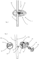
- Figure 1 shows a partial sectional view of a device 1 according to the invention.
- This has a tubular body 6 which is used to conduct a liquid, such as a pesticide.
- This tubular body 6 has a side opening 62 through which a flowable medium can enter an outlet device designated as a whole by 4.
- Reference character L denotes a longitudinal direction of the tubular body.
- the outlet device described in more detail below has a spring device 18, which can, for example, preload a check valve. In this way it can be achieved that liquid can only emerge from the outlet device above a certain pressure.
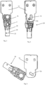
- Figure 2 shows an exploded representation of the in Figure 1 device shown.
- the outlet device has a clamping mechanism which enables the outlet device 4 to be clamped to the tubular body 6.
- the clamping mechanism has a first clamping part 42a and a second clamping part 42b. These can be arranged around the tubular body 6 and screwed together, so that overall the outlet device 4 is attached to the rod-shaped body 6.
- the first clamping body 42a has a recess 38 and the second clamping body 42b has a recess 36, which together at least partially surround the tubular body 6.
- the reference number 32 denotes seats for screw bodies, which can be inserted from the outside in order to screw the two clamping bodies 42a and 42b together.
- the reference numeral 34 denotes a pressing section which presses against the tubular body 6 in an assembled state.
- the reference numeral 64 denotes a sealing device by means of which a sealing effect can be produced between the clamping body 42a and the tubular body 6.
- Reference numeral 54 denotes a carrier which serves to accommodate a nozzle device 46 and a nozzle auxiliary section 52.
- reference number 56 denotes a seat within which the nozzle device 46 can be inserted.
- the Figures 3 to 5 show the attachment mechanism with which the device can be arranged on a vehicle.
- a carrier 12 is provided, which can be screwed to an area of the vehicle, for example.
- the reference numeral 20 denotes a holding device which serves to hold the tubular body 6.
- this holding device has a sleeve 22, which is suitable and intended for receiving the tubular body 6.
- the tubular body can be inserted into this sleeve and screwed to it via a screwing device 23.
- the reference number 2 denotes a supply line through which a flowable medium can be supplied to the tubular body 6.
- the reference number 26 denotes reinforcing webs.
- the reference numeral 16 denotes a pivoting element in order to pivot the holding device 20 relative to the carrier 12.
- the reference numeral 14 denotes an elongated projection which is formed in one piece on the holding device 20 and which can be guided in a predetermined pivoting position through an opening or receiving groove 12a which is formed in the carrier 12.
- Figure 5 shows an exploded view, again showing the carrier 12, as well as a receiving groove 12a to pivotally accommodate the element 16.
- the projection 14 and the receiving groove 12a run parallel to one another so that in this position the holding device 20 can be removed from the carrier.
- the projection 14 is preferably arranged on a circular bolt.
- the position shown is a position that is not assumed when the device according to the invention is in operation. However, the user can insert the tubular body into the in Fig. 5 Pivot the position shown and then remove the holding device 20 from the carrier 12.
Landscapes
- Engineering & Computer Science (AREA)
- Life Sciences & Earth Sciences (AREA)
- General Engineering & Computer Science (AREA)
- Insects & Arthropods (AREA)
- Pest Control & Pesticides (AREA)
- Wood Science & Technology (AREA)
- Zoology (AREA)
- Environmental Sciences (AREA)
- Mechanical Engineering (AREA)
- Catching Or Destruction (AREA)
- Fertilizing (AREA)
Priority Applications (2)
| Application Number | Priority Date | Filing Date | Title |
|---|---|---|---|
| PL18210322.6T PL3494789T5 (pl) | 2017-12-06 | 2018-12-05 | Urządzenie do rozprowadzania cieczy, nawozów, środków do zwalczania szkodników i tym podobnych |
| SI201830197T SI3494789T2 (sl) | 2017-12-06 | 2018-12-05 | Naprava za razprševanje tekočin, gnojil, sredstev za uničevanje škodljivcev in podobnega |
Applications Claiming Priority (1)
| Application Number | Priority Date | Filing Date | Title |
|---|---|---|---|
| DE102017129007.9A DE102017129007A1 (de) | 2017-12-06 | 2017-12-06 | Vorrichtung zum Ausbringen von Flüssigkeiten und insbesondere Düngemitteln, Schädlingsbekämpfungsmitteln und dergleichen |
Publications (3)
| Publication Number | Publication Date |
|---|---|
| EP3494789A1 EP3494789A1 (de) | 2019-06-12 |
| EP3494789B1 EP3494789B1 (de) | 2020-11-11 |
| EP3494789B2 true EP3494789B2 (de) | 2023-11-22 |
Family
ID=64606808
Family Applications (1)
| Application Number | Title | Priority Date | Filing Date |
|---|---|---|---|
| EP18210322.6A Active EP3494789B2 (de) | 2017-12-06 | 2018-12-05 | Vorrichtung zum ausbringen von flüssigkeiten, düngemitteln, schädlingsbekämpfungsmitteln und dergleichen |
Country Status (8)
| Country | Link |
|---|---|
| US (1) | US11592134B2 (hu) |
| EP (1) | EP3494789B2 (hu) |
| DE (1) | DE102017129007A1 (hu) |
| DK (1) | DK3494789T4 (hu) |
| HU (1) | HUE052529T2 (hu) |
| PL (1) | PL3494789T5 (hu) |
| PT (1) | PT3494789T (hu) |
| SI (1) | SI3494789T2 (hu) |
Families Citing this family (1)
| Publication number | Priority date | Publication date | Assignee | Title |
|---|---|---|---|---|
| DE102017129007A1 (de) * | 2017-12-06 | 2019-06-06 | Agrotop Gmbh | Vorrichtung zum Ausbringen von Flüssigkeiten und insbesondere Düngemitteln, Schädlingsbekämpfungsmitteln und dergleichen |
Citations (3)
| Publication number | Priority date | Publication date | Assignee | Title |
|---|---|---|---|---|
| US3515349A (en) † | 1968-03-20 | 1970-06-02 | Int Harvester Co | Boom assembly for sprayers |
| GB2229074A (en) † | 1989-01-17 | 1990-09-19 | Roger Sydney Benest | Spraying the underside of crops |
| US20160120117A1 (en) † | 2014-11-03 | 2016-05-05 | Rick Eugene LAWRENCE | Agricultural crop application system |
Family Cites Families (28)
| Publication number | Priority date | Publication date | Assignee | Title |
|---|---|---|---|---|
| GB733236A (en) * | 1952-12-04 | 1955-07-06 | Drake And Fletcher Ltd | Improvements in and relating to spray booms for agricultural purposes |
| US3117725A (en) * | 1962-05-01 | 1964-01-14 | Golden Arrow Mfg Ltd | Row crop sprayer |
| US3478967A (en) * | 1967-09-18 | 1969-11-18 | Subscription Television Inc | Row crop drop |
| US4915305A (en) * | 1982-09-30 | 1990-04-10 | Spraying Systems Co. | Spray nozzle boom mounting arrangement |
| US4736888A (en) * | 1985-06-26 | 1988-04-12 | Fasnacht Kenneth P | Row crop band sprayer |
| US5143298A (en) * | 1990-10-31 | 1992-09-01 | Man Roland Druckmaschinen Ag | Spray nozzle assembly with swivel mounted hollow cone spray tip |
| US5697650A (en) * | 1995-04-20 | 1997-12-16 | Spraying Systems Co. | Corrosion-free clip eyelet for spray nozzles |
| FR2772874B1 (fr) * | 1997-12-19 | 2000-01-28 | Saint Germain Et Straub Ets | Dispositif et procede de montage d'une selle de derivation sur une canalisation et robinet correspondant |
| US6152388A (en) * | 1999-05-24 | 2000-11-28 | Rohloff; Terry | Spray nozzle apparatus |
| DK1285193T3 (da) * | 2000-04-17 | 2005-10-17 | Skov As | Fremgangsmåde og midler til montering af forbindelsesstykker eller dyser på tynde, metalliske höjtryksrör |
| US6749134B2 (en) * | 2001-06-18 | 2004-06-15 | Spraying Systems Co. | Spray nozzle assembly with auxiliary high volume spray nozzle |
| DE10252242B3 (de) * | 2002-11-07 | 2004-08-19 | Alfons Kenter | Verfahren zum Herstellen einer Verbindung zum Befestigen einer Düse an einer Fluidleitung und Werkzeug dafür |
| DE102004056867A1 (de) * | 2004-11-25 | 2006-06-01 | John Deere Fabriek Horst B.V. | Düsenvorrichtung |
| DE102007017315A1 (de) * | 2007-04-11 | 2008-10-16 | John Deere Fabriek Horst B.V. | Spritzeinrichtung eines Spritzgestänges |
| BR112012025174B1 (pt) * | 2010-04-02 | 2021-02-17 | Sta-Rite Industries, Llc | dispositivo de aspiração de ar e conjunto aspirador de ar |
| US20120132730A1 (en) * | 2010-11-30 | 2012-05-31 | Agco Corporation | Enhanced Nozzle Body |
| US10076075B1 (en) * | 2011-08-16 | 2018-09-18 | 360 Yield Center, Llc | Liquid dispensing system |
| US10159178B2 (en) * | 2011-08-16 | 2018-12-25 | 360 Yield Center, Llc | Liquid dispensing system |
| ITMO20120263A1 (it) * | 2012-10-29 | 2014-04-30 | Arag S R L | Gruppo portagetti multiplo ad incrementata flessibilita' di impiego |
| US20140259897A1 (en) * | 2013-03-14 | 2014-09-18 | Agco Corporation | Infinitely Variable Planting or Spraying Device |
| US10189031B2 (en) * | 2014-06-20 | 2019-01-29 | Deere & Company | Hybrid flow nozzle and control system |
| GB2536961B (en) * | 2015-04-02 | 2021-02-24 | Exel Industries Sa | Irrigation system ground spikes |
| US10420333B2 (en) * | 2015-05-04 | 2019-09-24 | Deere & Company | Spray assembly for boom sprayer |
| US10849319B2 (en) * | 2016-06-10 | 2020-12-01 | 360 Yield Center, Llc | Liquid placement apparatus |
| US20180206474A1 (en) * | 2017-01-25 | 2018-07-26 | Robert Vaughan | Spray boom attachment system and methods of using same |
| US20180368387A1 (en) * | 2017-06-22 | 2018-12-27 | 360 Yield Center, Llc | Boom height sensor assembly |
| US10549303B2 (en) * | 2017-11-22 | 2020-02-04 | Cnh Industrial America Llc | Wire harness T-joint mount for an agricultural product sprayer |
| DE102017129007A1 (de) * | 2017-12-06 | 2019-06-06 | Agrotop Gmbh | Vorrichtung zum Ausbringen von Flüssigkeiten und insbesondere Düngemitteln, Schädlingsbekämpfungsmitteln und dergleichen |
-
2017
- 2017-12-06 DE DE102017129007.9A patent/DE102017129007A1/de active Pending
-
2018
- 2018-12-05 PL PL18210322.6T patent/PL3494789T5/pl unknown
- 2018-12-05 DK DK18210322.6T patent/DK3494789T4/da active
- 2018-12-05 EP EP18210322.6A patent/EP3494789B2/de active Active
- 2018-12-05 HU HUE18210322A patent/HUE052529T2/hu unknown
- 2018-12-05 PT PT182103226T patent/PT3494789T/pt unknown
- 2018-12-05 SI SI201830197T patent/SI3494789T2/sl unknown
- 2018-12-06 US US16/212,196 patent/US11592134B2/en active Active
Patent Citations (3)
| Publication number | Priority date | Publication date | Assignee | Title |
|---|---|---|---|---|
| US3515349A (en) † | 1968-03-20 | 1970-06-02 | Int Harvester Co | Boom assembly for sprayers |
| GB2229074A (en) † | 1989-01-17 | 1990-09-19 | Roger Sydney Benest | Spraying the underside of crops |
| US20160120117A1 (en) † | 2014-11-03 | 2016-05-05 | Rick Eugene LAWRENCE | Agricultural crop application system |
Non-Patent Citations (5)
| Title |
|---|
| Auszug der Internetseite klmag.ch vom 11. Oktober 2016 vonwww.archive.org † |
| Dropleg-Technik, Schweizer Bauer Dossier, 15. Marz 2014 † |
| Internetseite Agroscope - Impressum † |
| Internetseite https://ira.agroscope.ch/de-CH/Publication/32826 † |
| JACOB RÜEGG, RENÉ TOTAL: "Dropleg-Applikationstechnik für zielgerichteten Pflanzenschutz in Reihenkulturen - Einführung und Hinweise für Produzenten und Berater", FLUGSCHRIFT, 1 October 2013 (2013-10-01), pages 27pp † |
Also Published As
| Publication number | Publication date |
|---|---|
| DE102017129007A1 (de) | 2019-06-06 |
| PL3494789T3 (pl) | 2021-05-31 |
| SI3494789T1 (sl) | 2021-04-30 |
| EP3494789B1 (de) | 2020-11-11 |
| EP3494789A1 (de) | 2019-06-12 |
| HUE052529T2 (hu) | 2021-05-28 |
| US11592134B2 (en) | 2023-02-28 |
| DK3494789T3 (da) | 2021-02-15 |
| DK3494789T4 (da) | 2024-02-26 |
| US20190170282A1 (en) | 2019-06-06 |
| PL3494789T5 (pl) | 2024-03-04 |
| PT3494789T (pt) | 2020-12-07 |
| SI3494789T2 (sl) | 2024-03-29 |
Similar Documents
| Publication | Publication Date | Title |
|---|---|---|
| DE2431516C3 (de) | Vorrichtung zur Abgabe von Fluiden | |
| EP1254723A1 (de) | Spritzeinrichtung zum Versprühen von Flüssigkeiten, insbesondere für landwirtschaftliche Zwecke | |
| EP4286080A2 (de) | Schälgerät und spannbaugruppe | |
| EP3494789B2 (de) | Vorrichtung zum ausbringen von flüssigkeiten, düngemitteln, schädlingsbekämpfungsmitteln und dergleichen | |
| DE3401734A1 (de) | Spritz- bzw. spruehvorrichtung | |
| EP3180555B1 (de) | Anbohrarmatur | |
| WO2009060058A1 (de) | Verbindung eines sprühkopfes mit einem roboterarm | |
| WO1998055794A1 (de) | Rohrelement und damit ausgerüstete vorrichtung zum auftragen eines fluiden behandlungsmittels auf eine bahn | |
| EP2705750B1 (de) | Schleppschlauchverband | |
| DE102017216370A1 (de) | Vorrichtung Ausbringen eines Spritzmittels | |
| DE3624425C2 (de) | Einstellarmatur für Feldspritzleitungen | |
| DE202011051173U1 (de) | Lanze eines Hochdruckreinigungsgerätes und Hochdruckreinigungsgerät | |
| DE102021108314B4 (de) | Absperrhahn, Küken für einen Absperrhahn sowie Verfahren zur Herstellung eines Kükens für einen Absperrhahn | |
| DE102018218490A1 (de) | Landwirtschaftliche Spritzdüseneinheit | |
| EP2569096B1 (de) | Längenverstellbare sprühlanze mit längsverstellbarer handhabe | |
| DE6906168U (de) | Kupplungsvorrichtung | |
| EP3252358B1 (de) | Hydraulisches umschaltventil | |
| DE602006000265T2 (de) | Halter | |
| DE10354905A1 (de) | Glasfaserverstärktes Absperrventil für Betonschlauch | |
| DE1500075A1 (de) | Steuerventil fuer Spritzvorrichtungen od.dgl. | |
| DE1270871B (de) | Vorrichtung zum Verteilen und Einbringen von Ammoniak in den Boden bei einem Drehpflug | |
| EP4124227A1 (de) | Quetschventil, verteilervorrichtung für ein gülleausbringfahrzeug aufweisend ein quetschventil und verwendung eines quetschventils | |
| AT366536B (de) | Fahrbares saug-druck-fass | |
| DE3016611A1 (de) | Schlauchanschlussvorrichtung zum gemeinsamen anschliessen einer vielzahl von schlaeuchen an einem aggregat | |
| EP1066757A1 (de) | Teilbreitenbereichsleitung einer Spritzleitung einer Landwirtschaftlichen Feldspritze |
Legal Events
| Date | Code | Title | Description |
|---|---|---|---|
| PUAI | Public reference made under article 153(3) epc to a published international application that has entered the european phase |
Free format text: ORIGINAL CODE: 0009012 |
|
| STAA | Information on the status of an ep patent application or granted ep patent |
Free format text: STATUS: THE APPLICATION HAS BEEN PUBLISHED |
|
| AK | Designated contracting states |
Kind code of ref document: A1 Designated state(s): AL AT BE BG CH CY CZ DE DK EE ES FI FR GB GR HR HU IE IS IT LI LT LU LV MC MK MT NL NO PL PT RO RS SE SI SK SM TR |
|
| AX | Request for extension of the european patent |
Extension state: BA ME |
|
| STAA | Information on the status of an ep patent application or granted ep patent |
Free format text: STATUS: REQUEST FOR EXAMINATION WAS MADE |
|
| 17P | Request for examination filed |
Effective date: 20191212 |
|
| RBV | Designated contracting states (corrected) |
Designated state(s): AL AT BE BG CH CY CZ DE DK EE ES FI FR GB GR HR HU IE IS IT LI LT LU LV MC MK MT NL NO PL PT RO RS SE SI SK SM TR |
|
| GRAP | Despatch of communication of intention to grant a patent |
Free format text: ORIGINAL CODE: EPIDOSNIGR1 |
|
| STAA | Information on the status of an ep patent application or granted ep patent |
Free format text: STATUS: GRANT OF PATENT IS INTENDED |
|
| RIC1 | Information provided on ipc code assigned before grant |
Ipc: B05B 1/30 20060101ALN20200430BHEP Ipc: A01M 7/00 20060101AFI20200430BHEP Ipc: B05B 15/658 20180101ALI20200430BHEP |
|
| INTG | Intention to grant announced |
Effective date: 20200525 |
|
| RIC1 | Information provided on ipc code assigned before grant |
Ipc: B05B 15/658 20180101ALI20200512BHEP Ipc: A01M 7/00 20060101AFI20200512BHEP Ipc: B05B 1/30 20060101ALN20200512BHEP |
|
| GRAS | Grant fee paid |
Free format text: ORIGINAL CODE: EPIDOSNIGR3 |
|
| GRAA | (expected) grant |
Free format text: ORIGINAL CODE: 0009210 |
|
| STAA | Information on the status of an ep patent application or granted ep patent |
Free format text: STATUS: THE PATENT HAS BEEN GRANTED |
|
| AK | Designated contracting states |
Kind code of ref document: B1 Designated state(s): AL AT BE BG CH CY CZ DE DK EE ES FI FR GB GR HR HU IE IS IT LI LT LU LV MC MK MT NL NO PL PT RO RS SE SI SK SM TR |
|
| REG | Reference to a national code |
Ref country code: GB Ref legal event code: FG4D Free format text: NOT ENGLISH |
|
| REG | Reference to a national code |
Ref country code: CH Ref legal event code: EP |
|
| REG | Reference to a national code |
Ref country code: AT Ref legal event code: REF Ref document number: 1332568 Country of ref document: AT Kind code of ref document: T Effective date: 20201115 |
|
| REG | Reference to a national code |
Ref country code: CH Ref legal event code: NV Representative=s name: ROTTMANN, ZIMMERMANN + PARTNER AG, CH |
|
| REG | Reference to a national code |
Ref country code: DE Ref legal event code: R096 Ref document number: 502018002989 Country of ref document: DE |
|
| REG | Reference to a national code |
Ref country code: PT Ref legal event code: SC4A Ref document number: 3494789 Country of ref document: PT Date of ref document: 20201207 Kind code of ref document: T Free format text: AVAILABILITY OF NATIONAL TRANSLATION Effective date: 20201130 |
|
| REG | Reference to a national code |
Ref country code: IE Ref legal event code: FG4D Free format text: LANGUAGE OF EP DOCUMENT: GERMAN |
|
| REG | Reference to a national code |
Ref country code: NL Ref legal event code: FP |
|
| REG | Reference to a national code |
Ref country code: DK Ref legal event code: T3 Effective date: 20210208 |
|
| REG | Reference to a national code |
Ref country code: SK Ref legal event code: T3 Ref document number: E 36337 Country of ref document: SK |
|
| PG25 | Lapsed in a contracting state [announced via postgrant information from national office to epo] |
Ref country code: FI Free format text: LAPSE BECAUSE OF FAILURE TO SUBMIT A TRANSLATION OF THE DESCRIPTION OR TO PAY THE FEE WITHIN THE PRESCRIBED TIME-LIMIT Effective date: 20201111 Ref country code: RS Free format text: LAPSE BECAUSE OF FAILURE TO SUBMIT A TRANSLATION OF THE DESCRIPTION OR TO PAY THE FEE WITHIN THE PRESCRIBED TIME-LIMIT Effective date: 20201111 Ref country code: GR Free format text: LAPSE BECAUSE OF FAILURE TO SUBMIT A TRANSLATION OF THE DESCRIPTION OR TO PAY THE FEE WITHIN THE PRESCRIBED TIME-LIMIT Effective date: 20210212 Ref country code: NO Free format text: LAPSE BECAUSE OF FAILURE TO SUBMIT A TRANSLATION OF THE DESCRIPTION OR TO PAY THE FEE WITHIN THE PRESCRIBED TIME-LIMIT Effective date: 20210211 |
|
| REG | Reference to a national code |
Ref country code: HU Ref legal event code: AG4A Ref document number: E052529 Country of ref document: HU |
|
| PG25 | Lapsed in a contracting state [announced via postgrant information from national office to epo] |
Ref country code: SE Free format text: LAPSE BECAUSE OF FAILURE TO SUBMIT A TRANSLATION OF THE DESCRIPTION OR TO PAY THE FEE WITHIN THE PRESCRIBED TIME-LIMIT Effective date: 20201111 Ref country code: IS Free format text: LAPSE BECAUSE OF FAILURE TO SUBMIT A TRANSLATION OF THE DESCRIPTION OR TO PAY THE FEE WITHIN THE PRESCRIBED TIME-LIMIT Effective date: 20210311 Ref country code: LV Free format text: LAPSE BECAUSE OF FAILURE TO SUBMIT A TRANSLATION OF THE DESCRIPTION OR TO PAY THE FEE WITHIN THE PRESCRIBED TIME-LIMIT Effective date: 20201111 |
|
| REG | Reference to a national code |
Ref country code: LT Ref legal event code: MG9D |
|
| PG25 | Lapsed in a contracting state [announced via postgrant information from national office to epo] |
Ref country code: HR Free format text: LAPSE BECAUSE OF FAILURE TO SUBMIT A TRANSLATION OF THE DESCRIPTION OR TO PAY THE FEE WITHIN THE PRESCRIBED TIME-LIMIT Effective date: 20201111 |
|
| PG25 | Lapsed in a contracting state [announced via postgrant information from national office to epo] |
Ref country code: LT Free format text: LAPSE BECAUSE OF FAILURE TO SUBMIT A TRANSLATION OF THE DESCRIPTION OR TO PAY THE FEE WITHIN THE PRESCRIBED TIME-LIMIT Effective date: 20201111 Ref country code: SM Free format text: LAPSE BECAUSE OF FAILURE TO SUBMIT A TRANSLATION OF THE DESCRIPTION OR TO PAY THE FEE WITHIN THE PRESCRIBED TIME-LIMIT Effective date: 20201111 Ref country code: EE Free format text: LAPSE BECAUSE OF FAILURE TO SUBMIT A TRANSLATION OF THE DESCRIPTION OR TO PAY THE FEE WITHIN THE PRESCRIBED TIME-LIMIT Effective date: 20201111 |
|
| REG | Reference to a national code |
Ref country code: DE Ref legal event code: R026 Ref document number: 502018002989 Country of ref document: DE |
|
| PLBI | Opposition filed |
Free format text: ORIGINAL CODE: 0009260 |
|
| PG25 | Lapsed in a contracting state [announced via postgrant information from national office to epo] |
Ref country code: MC Free format text: LAPSE BECAUSE OF FAILURE TO SUBMIT A TRANSLATION OF THE DESCRIPTION OR TO PAY THE FEE WITHIN THE PRESCRIBED TIME-LIMIT Effective date: 20201111 |
|
| PLAX | Notice of opposition and request to file observation + time limit sent |
Free format text: ORIGINAL CODE: EPIDOSNOBS2 |
|
| 26 | Opposition filed |
Opponent name: LECHLER GMBH Effective date: 20210805 |
|
| PG25 | Lapsed in a contracting state [announced via postgrant information from national office to epo] |
Ref country code: IE Free format text: LAPSE BECAUSE OF NON-PAYMENT OF DUE FEES Effective date: 20201205 Ref country code: LU Free format text: LAPSE BECAUSE OF NON-PAYMENT OF DUE FEES Effective date: 20201205 Ref country code: AL Free format text: LAPSE BECAUSE OF FAILURE TO SUBMIT A TRANSLATION OF THE DESCRIPTION OR TO PAY THE FEE WITHIN THE PRESCRIBED TIME-LIMIT Effective date: 20201111 |
|
| PLBB | Reply of patent proprietor to notice(s) of opposition received |
Free format text: ORIGINAL CODE: EPIDOSNOBS3 |
|
| PG25 | Lapsed in a contracting state [announced via postgrant information from national office to epo] |
Ref country code: ES Free format text: LAPSE BECAUSE OF FAILURE TO SUBMIT A TRANSLATION OF THE DESCRIPTION OR TO PAY THE FEE WITHIN THE PRESCRIBED TIME-LIMIT Effective date: 20201111 |
|
| PG25 | Lapsed in a contracting state [announced via postgrant information from national office to epo] |
Ref country code: MT Free format text: LAPSE BECAUSE OF FAILURE TO SUBMIT A TRANSLATION OF THE DESCRIPTION OR TO PAY THE FEE WITHIN THE PRESCRIBED TIME-LIMIT Effective date: 20201111 Ref country code: CY Free format text: LAPSE BECAUSE OF FAILURE TO SUBMIT A TRANSLATION OF THE DESCRIPTION OR TO PAY THE FEE WITHIN THE PRESCRIBED TIME-LIMIT Effective date: 20201111 |
|
| PG25 | Lapsed in a contracting state [announced via postgrant information from national office to epo] |
Ref country code: MK Free format text: LAPSE BECAUSE OF FAILURE TO SUBMIT A TRANSLATION OF THE DESCRIPTION OR TO PAY THE FEE WITHIN THE PRESCRIBED TIME-LIMIT Effective date: 20201111 |
|
| REG | Reference to a national code |
Ref country code: CH Ref legal event code: PK Free format text: BERICHTIGUNGEN |
|
| PGFP | Annual fee paid to national office [announced via postgrant information from national office to epo] |
Ref country code: PL Payment date: 20221201 Year of fee payment: 5 |
|
| RIC2 | Information provided on ipc code assigned after grant |
Ipc: B05B 1/30 20060101ALN20230126BHEP Ipc: B05B 15/658 20180101ALI20230126BHEP Ipc: A01M 7/00 20060101AFI20230126BHEP |
|
| RIC2 | Information provided on ipc code assigned after grant |
Ipc: B05B 1/30 20060101ALN20230201BHEP Ipc: B05B 15/658 20180101ALI20230201BHEP Ipc: A01M 7/00 20060101AFI20230201BHEP |
|
| PLAB | Opposition data, opponent's data or that of the opponent's representative modified |
Free format text: ORIGINAL CODE: 0009299OPPO |
|
| REG | Reference to a national code |
Ref country code: CH Ref legal event code: PK Free format text: BERICHTIGUNGEN |
|
| R26 | Opposition filed (corrected) |
Opponent name: LECHLER GMBH Effective date: 20210805 |
|
| PGFP | Annual fee paid to national office [announced via postgrant information from national office to epo] |
Ref country code: IT Payment date: 20221230 Year of fee payment: 5 |
|
| P01 | Opt-out of the competence of the unified patent court (upc) registered |
Effective date: 20230521 |
|
| PUAH | Patent maintained in amended form |
Free format text: ORIGINAL CODE: 0009272 |
|
| STAA | Information on the status of an ep patent application or granted ep patent |
Free format text: STATUS: PATENT MAINTAINED AS AMENDED |
|
| 27A | Patent maintained in amended form |
Effective date: 20231122 |
|
| AK | Designated contracting states |
Kind code of ref document: B2 Designated state(s): AL AT BE BG CH CY CZ DE DK EE ES FI FR GB GR HR HU IE IS IT LI LT LU LV MC MK MT NL NO PL PT RO RS SE SI SK SM TR |
|
| REG | Reference to a national code |
Ref country code: DE Ref legal event code: R102 Ref document number: 502018002989 Country of ref document: DE |
|
| PGFP | Annual fee paid to national office [announced via postgrant information from national office to epo] |
Ref country code: SK Payment date: 20231130 Year of fee payment: 6 |
|
| PGFP | Annual fee paid to national office [announced via postgrant information from national office to epo] |
Ref country code: GB Payment date: 20231220 Year of fee payment: 6 |
|
| PGFP | Annual fee paid to national office [announced via postgrant information from national office to epo] |
Ref country code: TR Payment date: 20231127 Year of fee payment: 6 Ref country code: SI Payment date: 20231124 Year of fee payment: 6 Ref country code: RO Payment date: 20231127 Year of fee payment: 6 Ref country code: PT Payment date: 20231128 Year of fee payment: 6 Ref country code: NL Payment date: 20231219 Year of fee payment: 6 Ref country code: HU Payment date: 20231204 Year of fee payment: 6 Ref country code: FR Payment date: 20231219 Year of fee payment: 6 Ref country code: DK Payment date: 20231219 Year of fee payment: 6 Ref country code: CZ Payment date: 20231122 Year of fee payment: 6 Ref country code: BG Payment date: 20231220 Year of fee payment: 6 Ref country code: AT Payment date: 20231214 Year of fee payment: 6 |
|
| REG | Reference to a national code |
Ref country code: NL Ref legal event code: FP |
|
| REG | Reference to a national code |
Ref country code: DK Ref legal event code: T4 Effective date: 20240221 |
|
| PGFP | Annual fee paid to national office [announced via postgrant information from national office to epo] |
Ref country code: BE Payment date: 20231218 Year of fee payment: 6 |
|
| REG | Reference to a national code |
Ref country code: SK Ref legal event code: T5 Ref document number: E 36337 Country of ref document: SK |
|
| PG25 | Lapsed in a contracting state [announced via postgrant information from national office to epo] |
Ref country code: SK Free format text: LAPSE BECAUSE OF FAILURE TO SUBMIT A TRANSLATION OF THE DESCRIPTION OR TO PAY THE FEE WITHIN THE PRESCRIBED TIME-LIMIT Effective date: 20201111 |
|
| PGFP | Annual fee paid to national office [announced via postgrant information from national office to epo] |
Ref country code: DE Payment date: 20240131 Year of fee payment: 6 Ref country code: CH Payment date: 20240110 Year of fee payment: 6 |