EP3492794B1 - Anordnung zum ableiten von blow-by-gasen aus einem kurbelgehäuse eines verbrennungsmotors - Google Patents
Anordnung zum ableiten von blow-by-gasen aus einem kurbelgehäuse eines verbrennungsmotors Download PDFInfo
- Publication number
- EP3492794B1 EP3492794B1 EP18207711.5A EP18207711A EP3492794B1 EP 3492794 B1 EP3492794 B1 EP 3492794B1 EP 18207711 A EP18207711 A EP 18207711A EP 3492794 B1 EP3492794 B1 EP 3492794B1
- Authority
- EP
- European Patent Office
- Prior art keywords
- hose
- line
- blow
- diagnostic
- coupling part
- Prior art date
- Legal status (The legal status is an assumption and is not a legal conclusion. Google has not performed a legal analysis and makes no representation as to the accuracy of the status listed.)
- Active
Links
Images


Classifications
-
- F—MECHANICAL ENGINEERING; LIGHTING; HEATING; WEAPONS; BLASTING
- F01—MACHINES OR ENGINES IN GENERAL; ENGINE PLANTS IN GENERAL; STEAM ENGINES
- F01M—LUBRICATING OF MACHINES OR ENGINES IN GENERAL; LUBRICATING INTERNAL COMBUSTION ENGINES; CRANKCASE VENTILATING
- F01M13/00—Crankcase ventilating or breathing
- F01M13/0011—Breather valves
-
- F—MECHANICAL ENGINEERING; LIGHTING; HEATING; WEAPONS; BLASTING
- F01—MACHINES OR ENGINES IN GENERAL; ENGINE PLANTS IN GENERAL; STEAM ENGINES
- F01M—LUBRICATING OF MACHINES OR ENGINES IN GENERAL; LUBRICATING INTERNAL COMBUSTION ENGINES; CRANKCASE VENTILATING
- F01M13/00—Crankcase ventilating or breathing
- F01M13/02—Crankcase ventilating or breathing by means of additional source of positive or negative pressure
- F01M13/021—Crankcase ventilating or breathing by means of additional source of positive or negative pressure of negative pressure
- F01M13/022—Crankcase ventilating or breathing by means of additional source of positive or negative pressure of negative pressure using engine inlet suction
-
- F—MECHANICAL ENGINEERING; LIGHTING; HEATING; WEAPONS; BLASTING
- F01—MACHINES OR ENGINES IN GENERAL; ENGINE PLANTS IN GENERAL; STEAM ENGINES
- F01M—LUBRICATING OF MACHINES OR ENGINES IN GENERAL; LUBRICATING INTERNAL COMBUSTION ENGINES; CRANKCASE VENTILATING
- F01M11/00—Component parts, details or accessories, not provided for in, or of interest apart from, groups F01M1/00 - F01M9/00
- F01M11/10—Indicating devices; Other safety devices
-
- F—MECHANICAL ENGINEERING; LIGHTING; HEATING; WEAPONS; BLASTING
- F01—MACHINES OR ENGINES IN GENERAL; ENGINE PLANTS IN GENERAL; STEAM ENGINES
- F01M—LUBRICATING OF MACHINES OR ENGINES IN GENERAL; LUBRICATING INTERNAL COMBUSTION ENGINES; CRANKCASE VENTILATING
- F01M13/00—Crankcase ventilating or breathing
-
- F—MECHANICAL ENGINEERING; LIGHTING; HEATING; WEAPONS; BLASTING
- F01—MACHINES OR ENGINES IN GENERAL; ENGINE PLANTS IN GENERAL; STEAM ENGINES
- F01M—LUBRICATING OF MACHINES OR ENGINES IN GENERAL; LUBRICATING INTERNAL COMBUSTION ENGINES; CRANKCASE VENTILATING
- F01M13/00—Crankcase ventilating or breathing
- F01M13/02—Crankcase ventilating or breathing by means of additional source of positive or negative pressure
- F01M13/021—Crankcase ventilating or breathing by means of additional source of positive or negative pressure of negative pressure
-
- F—MECHANICAL ENGINEERING; LIGHTING; HEATING; WEAPONS; BLASTING
- F01—MACHINES OR ENGINES IN GENERAL; ENGINE PLANTS IN GENERAL; STEAM ENGINES
- F01M—LUBRICATING OF MACHINES OR ENGINES IN GENERAL; LUBRICATING INTERNAL COMBUSTION ENGINES; CRANKCASE VENTILATING
- F01M13/00—Crankcase ventilating or breathing
- F01M13/04—Crankcase ventilating or breathing having means for purifying air before leaving crankcase, e.g. removing oil
-
- F—MECHANICAL ENGINEERING; LIGHTING; HEATING; WEAPONS; BLASTING
- F02—COMBUSTION ENGINES; HOT-GAS OR COMBUSTION-PRODUCT ENGINE PLANTS
- F02D—CONTROLLING COMBUSTION ENGINES
- F02D41/00—Electrical control of supply of combustible mixture or its constituents
- F02D41/22—Safety or indicating devices for abnormal conditions
-
- F—MECHANICAL ENGINEERING; LIGHTING; HEATING; WEAPONS; BLASTING
- F02—COMBUSTION ENGINES; HOT-GAS OR COMBUSTION-PRODUCT ENGINE PLANTS
- F02M—SUPPLYING COMBUSTION ENGINES IN GENERAL WITH COMBUSTIBLE MIXTURES OR CONSTITUENTS THEREOF
- F02M25/00—Engine-pertinent apparatus for adding non-fuel substances or small quantities of secondary fuel to combustion-air, main fuel or fuel-air mixture
- F02M25/06—Engine-pertinent apparatus for adding non-fuel substances or small quantities of secondary fuel to combustion-air, main fuel or fuel-air mixture adding lubricant vapours
-
- F—MECHANICAL ENGINEERING; LIGHTING; HEATING; WEAPONS; BLASTING
- F02—COMBUSTION ENGINES; HOT-GAS OR COMBUSTION-PRODUCT ENGINE PLANTS
- F02M—SUPPLYING COMBUSTION ENGINES IN GENERAL WITH COMBUSTIBLE MIXTURES OR CONSTITUENTS THEREOF
- F02M35/00—Combustion-air cleaners, air intakes, intake silencers, or induction systems specially adapted for, or arranged on, internal-combustion engines
- F02M35/10—Air intakes; Induction systems
- F02M35/10091—Air intakes; Induction systems characterised by details of intake ducts: shapes; connections; arrangements
- F02M35/10144—Connections of intake ducts to each other or to another device
-
- F—MECHANICAL ENGINEERING; LIGHTING; HEATING; WEAPONS; BLASTING
- F02—COMBUSTION ENGINES; HOT-GAS OR COMBUSTION-PRODUCT ENGINE PLANTS
- F02M—SUPPLYING COMBUSTION ENGINES IN GENERAL WITH COMBUSTIBLE MIXTURES OR CONSTITUENTS THEREOF
- F02M35/00—Combustion-air cleaners, air intakes, intake silencers, or induction systems specially adapted for, or arranged on, internal-combustion engines
- F02M35/10—Air intakes; Induction systems
- F02M35/10209—Fluid connections to the air intake system; their arrangement of pipes, valves or the like
- F02M35/10222—Exhaust gas recirculation [EGR]; Positive crankcase ventilation [PCV]; Additional air admission, lubricant or fuel vapour admission
-
- F—MECHANICAL ENGINEERING; LIGHTING; HEATING; WEAPONS; BLASTING
- F16—ENGINEERING ELEMENTS AND UNITS; GENERAL MEASURES FOR PRODUCING AND MAINTAINING EFFECTIVE FUNCTIONING OF MACHINES OR INSTALLATIONS; THERMAL INSULATION IN GENERAL
- F16J—PISTONS; CYLINDERS; SEALINGS
- F16J15/00—Sealings
- F16J15/02—Sealings between relatively-stationary surfaces
-
- F—MECHANICAL ENGINEERING; LIGHTING; HEATING; WEAPONS; BLASTING
- F16—ENGINEERING ELEMENTS AND UNITS; GENERAL MEASURES FOR PRODUCING AND MAINTAINING EFFECTIVE FUNCTIONING OF MACHINES OR INSTALLATIONS; THERMAL INSULATION IN GENERAL
- F16L—PIPES; JOINTS OR FITTINGS FOR PIPES; SUPPORTS FOR PIPES, CABLES OR PROTECTIVE TUBING; MEANS FOR THERMAL INSULATION IN GENERAL
- F16L25/00—Construction or details of pipe joints not provided for in, or of interest apart from, groups F16L13/00 - F16L23/00
- F16L25/0036—Joints for corrugated pipes
- F16L25/0045—Joints for corrugated pipes of the quick-acting type
-
- F—MECHANICAL ENGINEERING; LIGHTING; HEATING; WEAPONS; BLASTING
- F16—ENGINEERING ELEMENTS AND UNITS; GENERAL MEASURES FOR PRODUCING AND MAINTAINING EFFECTIVE FUNCTIONING OF MACHINES OR INSTALLATIONS; THERMAL INSULATION IN GENERAL
- F16L—PIPES; JOINTS OR FITTINGS FOR PIPES; SUPPORTS FOR PIPES, CABLES OR PROTECTIVE TUBING; MEANS FOR THERMAL INSULATION IN GENERAL
- F16L33/00—Arrangements for connecting hoses to rigid members; Rigid hose-connectors, i.e. single members engaging both hoses
- F16L33/01—Arrangements for connecting hoses to rigid members; Rigid hose-connectors, i.e. single members engaging both hoses specially adapted for hoses having a multi-layer wall
-
- F—MECHANICAL ENGINEERING; LIGHTING; HEATING; WEAPONS; BLASTING
- F16—ENGINEERING ELEMENTS AND UNITS; GENERAL MEASURES FOR PRODUCING AND MAINTAINING EFFECTIVE FUNCTIONING OF MACHINES OR INSTALLATIONS; THERMAL INSULATION IN GENERAL
- F16L—PIPES; JOINTS OR FITTINGS FOR PIPES; SUPPORTS FOR PIPES, CABLES OR PROTECTIVE TUBING; MEANS FOR THERMAL INSULATION IN GENERAL
- F16L39/00—Joints or fittings for double-walled or multi-channel pipes or pipe assemblies
-
- F—MECHANICAL ENGINEERING; LIGHTING; HEATING; WEAPONS; BLASTING
- F16—ENGINEERING ELEMENTS AND UNITS; GENERAL MEASURES FOR PRODUCING AND MAINTAINING EFFECTIVE FUNCTIONING OF MACHINES OR INSTALLATIONS; THERMAL INSULATION IN GENERAL
- F16L—PIPES; JOINTS OR FITTINGS FOR PIPES; SUPPORTS FOR PIPES, CABLES OR PROTECTIVE TUBING; MEANS FOR THERMAL INSULATION IN GENERAL
- F16L39/00—Joints or fittings for double-walled or multi-channel pipes or pipe assemblies
- F16L39/005—Joints or fittings for double-walled or multi-channel pipes or pipe assemblies for concentric pipes
-
- F—MECHANICAL ENGINEERING; LIGHTING; HEATING; WEAPONS; BLASTING
- F16—ENGINEERING ELEMENTS AND UNITS; GENERAL MEASURES FOR PRODUCING AND MAINTAINING EFFECTIVE FUNCTIONING OF MACHINES OR INSTALLATIONS; THERMAL INSULATION IN GENERAL
- F16L—PIPES; JOINTS OR FITTINGS FOR PIPES; SUPPORTS FOR PIPES, CABLES OR PROTECTIVE TUBING; MEANS FOR THERMAL INSULATION IN GENERAL
- F16L39/00—Joints or fittings for double-walled or multi-channel pipes or pipe assemblies
- F16L39/02—Joints or fittings for double-walled or multi-channel pipes or pipe assemblies for hoses
-
- G—PHYSICS
- G01—MEASURING; TESTING
- G01M—TESTING STATIC OR DYNAMIC BALANCE OF MACHINES OR STRUCTURES; TESTING OF STRUCTURES OR APPARATUS, NOT OTHERWISE PROVIDED FOR
- G01M3/00—Investigating fluid-tightness of structures
- G01M3/02—Investigating fluid-tightness of structures by using fluid or vacuum
- G01M3/26—Investigating fluid-tightness of structures by using fluid or vacuum by measuring rate of loss or gain of fluid, e.g. by pressure-responsive devices, by flow detectors
- G01M3/28—Investigating fluid-tightness of structures by using fluid or vacuum by measuring rate of loss or gain of fluid, e.g. by pressure-responsive devices, by flow detectors for pipes, cables or tubes; for pipe joints or seals; for valves ; for welds
- G01M3/2807—Investigating fluid-tightness of structures by using fluid or vacuum by measuring rate of loss or gain of fluid, e.g. by pressure-responsive devices, by flow detectors for pipes, cables or tubes; for pipe joints or seals; for valves ; for welds for pipes
- G01M3/2815—Investigating fluid-tightness of structures by using fluid or vacuum by measuring rate of loss or gain of fluid, e.g. by pressure-responsive devices, by flow detectors for pipes, cables or tubes; for pipe joints or seals; for valves ; for welds for pipes using pressure measurements
-
- F—MECHANICAL ENGINEERING; LIGHTING; HEATING; WEAPONS; BLASTING
- F01—MACHINES OR ENGINES IN GENERAL; ENGINE PLANTS IN GENERAL; STEAM ENGINES
- F01M—LUBRICATING OF MACHINES OR ENGINES IN GENERAL; LUBRICATING INTERNAL COMBUSTION ENGINES; CRANKCASE VENTILATING
- F01M13/00—Crankcase ventilating or breathing
- F01M13/02—Crankcase ventilating or breathing by means of additional source of positive or negative pressure
- F01M13/021—Crankcase ventilating or breathing by means of additional source of positive or negative pressure of negative pressure
- F01M2013/027—Crankcase ventilating or breathing by means of additional source of positive or negative pressure of negative pressure with a turbo charger or compressor
-
- F—MECHANICAL ENGINEERING; LIGHTING; HEATING; WEAPONS; BLASTING
- F01—MACHINES OR ENGINES IN GENERAL; ENGINE PLANTS IN GENERAL; STEAM ENGINES
- F01M—LUBRICATING OF MACHINES OR ENGINES IN GENERAL; LUBRICATING INTERNAL COMBUSTION ENGINES; CRANKCASE VENTILATING
- F01M13/00—Crankcase ventilating or breathing
- F01M13/04—Crankcase ventilating or breathing having means for purifying air before leaving crankcase, e.g. removing oil
- F01M2013/0488—Crankcase ventilating or breathing having means for purifying air before leaving crankcase, e.g. removing oil with oil trap in the return conduit to the crankcase
-
- F—MECHANICAL ENGINEERING; LIGHTING; HEATING; WEAPONS; BLASTING
- F01—MACHINES OR ENGINES IN GENERAL; ENGINE PLANTS IN GENERAL; STEAM ENGINES
- F01M—LUBRICATING OF MACHINES OR ENGINES IN GENERAL; LUBRICATING INTERNAL COMBUSTION ENGINES; CRANKCASE VENTILATING
- F01M2250/00—Measuring
- F01M2250/60—Operating parameters
-
- F—MECHANICAL ENGINEERING; LIGHTING; HEATING; WEAPONS; BLASTING
- F02—COMBUSTION ENGINES; HOT-GAS OR COMBUSTION-PRODUCT ENGINE PLANTS
- F02D—CONTROLLING COMBUSTION ENGINES
- F02D2250/00—Engine control related to specific problems or objectives
- F02D2250/08—Engine blow-by from crankcase chamber
-
- F—MECHANICAL ENGINEERING; LIGHTING; HEATING; WEAPONS; BLASTING
- F16—ENGINEERING ELEMENTS AND UNITS; GENERAL MEASURES FOR PRODUCING AND MAINTAINING EFFECTIVE FUNCTIONING OF MACHINES OR INSTALLATIONS; THERMAL INSULATION IN GENERAL
- F16L—PIPES; JOINTS OR FITTINGS FOR PIPES; SUPPORTS FOR PIPES, CABLES OR PROTECTIVE TUBING; MEANS FOR THERMAL INSULATION IN GENERAL
- F16L2201/00—Special arrangements for pipe couplings
- F16L2201/30—Detecting leaks
-
- Y—GENERAL TAGGING OF NEW TECHNOLOGICAL DEVELOPMENTS; GENERAL TAGGING OF CROSS-SECTIONAL TECHNOLOGIES SPANNING OVER SEVERAL SECTIONS OF THE IPC; TECHNICAL SUBJECTS COVERED BY FORMER USPC CROSS-REFERENCE ART COLLECTIONS [XRACs] AND DIGESTS
- Y02—TECHNOLOGIES OR APPLICATIONS FOR MITIGATION OR ADAPTATION AGAINST CLIMATE CHANGE
- Y02T—CLIMATE CHANGE MITIGATION TECHNOLOGIES RELATED TO TRANSPORTATION
- Y02T10/00—Road transport of goods or passengers
- Y02T10/10—Internal combustion engine [ICE] based vehicles
- Y02T10/40—Engine management systems
Definitions
- the invention relates to an arrangement for diverting blow-by gases from a crankcase of an internal combustion engine with the features of the preamble of claim 1.
- blow-by gases During operation of an internal combustion engine, blow-by gases get into a crankcase of the internal combustion engine due to unavoidable leaks between the piston and the cylinder.
- the blow-by gases are discharged with the help of a hose device so that there is no inadmissibly high pressure in the crankcase.
- the blow-by gases are fed to the fresh air system. This means that the blow-by gases can be fed back into the combustion engine.
- the hose device has a blow-by line.
- a hose is connected to a line of the fresh air system via a connecting piece.
- the hose is plugged with an outlet section directly onto the inlet section of the connecting piece.
- the hose is designed at least at its outlet section in such a way that it is reversibly deformed when it is attached to the inlet section of the connecting piece.
- the at least one side opening is designed as an elongated hole that extends over 30 ° to 45 ° in the circumferential direction.
- the connecting piece is designed with two annular grooves at its entry section. A sealing ring is used in each of these annular grooves.
- the hose is designed as a corrugated hose.
- This arrangement shows a Coupling system for connecting a hose to a socket.
- the hose has a connector which can be inserted into the socket and which has at least one annular groove and a fastening contour on its outside.
- the socket has a latching contour on its outside.
- a coupling element which is produced separately with respect to the socket and the connecting piece is provided, which is pushed onto the outside of the connecting piece, the coupling element having a plurality of latching hooks which engage behind the latching contour.
- the coupling element has at least one fastening hook which cooperates with the fastening contour to axially fix the coupling element on the connecting piece.
- the hose can be designed as a blow molded part together with the respective nozzle.
- Each of the locking hooks is provided with a release lever. By actuating the release lever, the respective locking hook can be disengaged from the locking contour.
- the release levers form an extension of the respective locking hook.
- One area of a base ring acts as a pivot bearing for the latching hooks lengthened by the release lever.
- the generic arrangement is not yet optimally designed.
- the connection of the hoses is simplified, but it is desirable to reliably avoid leaky or incorrectly assembled hose arrangements.
- the WO 02/103236 A1 relates generally to the field of hydraulic equipment and systems.
- the WO 02/103236 A1 discloses a recovery device for collecting fluid emerging from a hydraulic fluid line and for returning the fluid to the hydraulic system.
- the device can be installed in any hydraulically powered machine, such as. B. in a garbage compactor or in cargo transportation equipment on a ship.
- the device comprises an inner fluid line which has a certain outer diameter and is used to convey hydraulic fluid between two points in a hydraulic system, for example between a fluid pump and a fluid-operated mechanism.
- the device also includes a reinforcement sleeve having an inner diameter of the reinforcement sleeve that is greater than the outer diameter of the inner fluid conduit for receiving the inner fluid conduit.
- the device also comprises an outer fluid line with an inner diameter of the outer fluid line which is larger than the outer diameter of the reinforcement sleeve to receive the reinforcement sleeve and the inner fluid line, so that a substantially annular receiving space is provided between the reinforcement sleeve and the outer fluid line.
- the inner and outer fluid lines are concentric at a first higher pressure fluid line end with a Coupling structure and connected at a second fluid line end with lower pressure to a distributor structure.
- the pipe retention system has a connector for use with metal pipes, the connector comprising: an adapter, the adapter having a longitudinal channel for fluid flow; a body for receiving the hose; a metal seal member disposed between the adapter and the body; A mother; a jacket locking ring positioned radially inward of a portion of the nut, the jacket locking ring for making a mechanical connection with an outer jacket of the hose; and at least one fastener connecting the nut, the body and the adapter.
- crankcase ventilation for an internal combustion engine.
- the crankcase ventilation has at least one ventilation line for discharging a gas from a crankcase of the internal combustion engine, at least one envelope element being provided which surrounds at least a partial area of the ventilation line on the outside circumference and is spaced from the partial area, so that a diagnostic volume is limited by the partial area and the envelope element , which is fluidly connected to a regeneration line for regenerating an adsorption filter of the internal combustion engine.
- the invention is therefore based on the object of avoiding the risk of leaky or incorrectly assembled hose devices.
- the hose device has a diagnostic line, with a faulty air flow being detectable via the diagnostic line if the hose device is leaky or is connected or not connected in a leaky manner.
- This has the advantage that the functioning of the hose device for venting is reliably guaranteed. If the hose device is correctly installed and the hose device itself is not leaking, no incorrect air flow will flow through the diagnostic line. However, if the hose assembly is leaking, it is not properly connected is or is not connected at all, then a defective air flow flows through the diagnosis line, which is detected by means of a pressure sensor. The defective air flow leads to the fresh air system, in particular to the intake manifold.
- a free, open end of the diagnostic line is in sealing contact with a component.
- the outer shell is attached to the turbocharger housing as a blind, sealed end.
- a sealing ring is preferably arranged between the end face of the coupling part, which forms the end of the diagnostic line, and the component, in order to ensure the tightness of the connection.
- the hose device has a tube-in-tube construction.
- the hose device has an inner hose and an outer hose, the inner hose being arranged inside the outer hose.
- the blow-by gases are now discharged through the inner hose.
- the inner hose thus serves as a blow-by line.
- blow-by gases are pumped from the oil separator into the fresh air tract.
- the exhaust gas turbocharger ensures a high pressure build-up and there is increased pressure in the intake manifold.
- a negative pressure arises in the intake manifold and the turbocharger delivers little or no pressure build-up.
- the outer hose and / or the inner hose are designed as a corrugated hose.
- the hose device has a coupling part, the inner hose engaging a first outer peripheral surface of the coupling part and the outer hose engaging a second outer peripheral surface, an inlet opening opening into an external line in the coupling part, the external line serving as a diagnostic line.
- the hose device can be connected on the one hand to an oil separator housing, the oil separator housing being in fluid connection with a suction pipe and the oil separating housing having a diagnostic channel in fluid connection with the diagnostic line.
- a pressure fluctuation in the diagnostic channel can be detected by means of a pressure sensor.
- the defective air flow is led into the intake manifold and can can be detected there by means of a pressure sensor.
- an opening to the outside air is created so that the intake manifold can suck in air. This defective air is recognized by a gas exchange control of the internal combustion engine, whereupon an error is recognized and output.
- the coupling part represents the connection between the inner hose and the outer hose and, for example, the connecting piece.
- the coupling part has a first outer circumferential surface onto which the inner hose is slipped.
- the coupling part has a second outer circumferential surface onto which the outer hose is slipped.
- the coupling part can be designed essentially tubular. The blow-by gases from the inner hose can now be passed on through this inner line.
- the coupling part has an outer line which in particular extends at least partially in a jacket surface of the coupling part. The fault current of the diagnostic line can be passed on to the diagnostic channel through this external line.
- This outer line has an opening on an outer circumferential surface which is delimited by an inner circumferential surface of the connecting piece in the inserted state.
- This interior space is preferably delimited by two seals, in particular corresponding O-rings, arranged on the outer circumference of the inner part.
- a connection that is particularly easy to assemble is provided in that the coupling part can be connected to a socket by means of a latching connection.
- the latching connection can be formed in a manner that is easy to produce in that at least one latching lug is formed on the outer ring, the at least one latching lug cooperating with a holding contour formed on an outer circumferential surface of the connecting piece.
- the hose device can be connected to the oil separator housing, the oil separator housing having a diagnostic channel which is in fluid connection with the suction pipe and the diagnostic line.
- the defective air flow is passed on to the intake manifold via this diagnostic channel.
- a corresponding sensor, which detects the defective air flow, can be arranged in the intake manifold.
- the sensor can be designed as a pressure sensor.
- One component in particular the oil separator, has a connecting piece.
- the hose device has a coupling part at each end.
- a corresponding coupling part is arranged at each end, wherein the coupling parts do not have to be constructed identically.
- the coupling part can itself be designed in two parts or in several parts. These two or more parts can be connected to one another by a welded connection, an adhesive connection, a plug connection or the like in order to achieve a connection that is as tight as possible.
- the connection piece and the coupling part are preferably connected to one another via a latching connection.
- the latching connection is designed, in particular, to be openable.
- the coupling part can have a ring encompassing the connection piece on the outside, the ring interacting with the outer surface of the connection piece via a latching connection.
- the ring can have corresponding latching lugs which engage in a latching contour on the outer circumferential surface of the connecting piece in the assembled state. This is a particularly easy-to-use connection.
- the hose device can be connected to the corresponding components by a screw connection.
- blow-by gases 5 can be fed to a fresh air system 3 via a hose device 2. Only part of an exhaust gas turbocharger housing 4 is shown here.
- the corresponding blow-by gases 5 (indicated here by corresponding arrows) are conducted from an oil separator 6 through the hose device 2 to the compressor side of the exhaust gas turbocharger.
- the oil separator 6 in particular the corresponding oil separator housing 7 is shown here.
- the oil separator 6 is in fluid communication with the crankcase.
- the hose device 2 is connected on the one hand to a component 8 assigned to the fresh air system, namely on the exhaust gas turbocharger housing 4, and on the other hand to a component 9 in fluid connection with the crankcase, namely a connector 10 here.
- the connector 10 is mounted on the oil separator housing 7.
- the hose device 2 now has a blow-by line 11.
- the hose device 2 has a diagnostic line 12, with an incorrect air flow 13 being detectable via the diagnostic line 12 if the hose device 2 is leaky, is not connected or is not connected at all.
- the defective air flow 13 is again indicated here by corresponding arrows.
- the diagnostic line 12 ends blindly at an end face 14 on the exhaust gas turbocharger housing 4.
- a sealing ring 15 is arranged here between the end faces of the mouth of the diagnostic line 12 and the exhaust gas turbocharger housing 4 or the end face 14.
- the hose device 2 has an outer hose 16 and an inner hose 17.
- the inner tube 17 serves as a blow-by line, i.e. inside the inner tube 17 the blow-by gases 5 are passed on.
- the outer tube 16 has a larger diameter than the inner tube 17.
- An annular space 18, which forms part of the diagnostic line 12, remains between the outer hose 16 and the inner hose 17.
- the hose device 2 now has two coupling parts 19, 20.
- the coupling parts 19, 20 have on the hose side, ie in the direction of the outer hose 16 and the inner hose 17, a first outer circumferential surface 21 onto which the inner hose 17 is slipped. Furthermore, the coupling parts 19, 20 have a second outer circumferential surface 22 onto which the outer hose 16 is slipped. Between the first outer circumferential surface 21 and the second outer circumferential surface 22 there is at least one inlet opening 23, in particular are a plurality of inlet openings 23 are formed which open into an external line 24. The external line 24 forms part of the diagnostic line 12.
- the coupling parts 19, 20 are tubular and conduct the blow-by gases in their interior, i.e. in the corresponding cylindrical cavity 25.
- the cavity 25 thus forms part of the blow-by line 11.
- This first region of the coupling parts 19, 20 can be formed by a first component 26 and 27, respectively.
- a component 28, in particular an angled component, is provided here, which is welded to component 27, for example, or is connected by an adhesive connection or a flight connection.
- the component 28 now has a channel 29 for the blow-by gases and a channel 30 which forms part of the diagnostic service 12.
- the channel 30 ends at the front on the exhaust gas turbocharger housing 4 and is arranged there in a sealing manner with the sealing ring 15.
- the channel 30 extends somewhat further into the exhaust gas turbocharger housing 4 and is arranged there in a sealing manner on the outer circumferential surface by means of a sealing ring 31.
- a correspondingly tubular edge area 32 delimits the channel 30.
- the sealing ring 31 rests on the outer circumferential surface of the tubular wall area 32.
- the component 26 is connected to a further component 33 in which the external line 24 is continued.
- the outer line 24 emerges here at an outer circumferential surface 34, which lies between two annular grooves 35, 36.
- O-rings 37, 38 are arranged in each of the annular grooves 35, 36.
- the outer circumferential surface 34 delimits a part of an annular space with an inner circumferential surface 39 of the connector 10.
- a diagnostic channel 40 extends from the inner peripheral surface 39 within the component 9 or the corresponding connector 10, which in turn opens into a further diagnostic channel 41 in the exhaust gas turbocharger housing 4.
- the O-rings 37, 38 here seal the annular space between the outer circumferential surface 34 from the corresponding adjacent inner circumferential surfaces of the connecting piece 10.
- the coupling part 19 is screwed in particular to the exhaust gas turbocharger housing 4.
- the coupling part 20 is connected to the socket 10 by means of a latching connection.
- the coupling part 20 has an outer ring 42 on which at least one locking lug 43 is formed.
- the outer ring 42 is connected to the rest of the body via two arms 44. If the component 9 is now pushed onto the connecting piece 10, the locking lugs 43 are pushed onto the outer circumference of the connecting piece 10 via a retaining contour 45 and snap into place there.
Landscapes
- Engineering & Computer Science (AREA)
- General Engineering & Computer Science (AREA)
- Mechanical Engineering (AREA)
- Chemical & Material Sciences (AREA)
- Combustion & Propulsion (AREA)
- Physics & Mathematics (AREA)
- General Physics & Mathematics (AREA)
- Lubrication Details And Ventilation Of Internal Combustion Engines (AREA)
Description
- Die Erfindung betrifft eine Anordnung zum Ableiten von Blow-By-Gasen aus einem Kurbelgehäuse eines Verbrennungsmotors mit den Merkmalen des Oberbegriffs des Patentanspruchs 1.
- Im Betrieb eines Verbrennungsmotors gelangen Blow-By-Gase aufgrund unvermeidlicher Leckagen zwischen dem Kolben und dem Zylinder in ein Kurbelgehäuse des Verbrennungsmotors. Damit im Kurbelgehäuse kein unzulässig hoher Druck entsteht, werden die Blow-By-Gase mit Hilfe einer Schlauchvorrichtung abgeführt. Um dabei eine Umweltverschmutzung durch die schadstoffbeladenen Blow-By-Gase zu vermeiden, werden die Blow-By-Gase der Frischluftanlage zugeleitet. Damit können die Blow-By-Gase erneut der Verbrennung im Verbrennungsmotor zugeführt werden. Die Schlauchvorrichtung weist dazu eine Blow-By-Leitung auf.
- Um die Schlauchvorrichtung an die entsprechenden Bauteile anzuschließen, sind nun im Stand der Technik verschiedene Möglichkeiten bekannt.
- Aus der
DE 2004 063 459 A1 ist eine Anordnung bekannt, wobei ein Schlauch über einen Stutzen an eine Leitung der Frischluftanlage angeschlossen ist. Der Schlauch wird dazu mit einem Austrittsabschnitt direkt auf den Eintrittsabschnitt des Stutzens aufgesteckt. Zur Sicherung der Verbindung ist wenigstens eine fensterartige Seitenöffnung im Austrittsabschnitt vorhanden, in welche ein am Eintrittsabschnitt ausgebildeter Widerhaken eingreift. Der Schlauch ist zumindest an seinem Austrittsabschnitt durch die Formgebung und/oder die Materialauswahl so ausgestaltet, dass er sich beim Aufstecken auf den Eintrittsabschnitt des Stutzens reversibel verformt. Die wenigstens eine Seitenöffnung ist als Langloch ausgestaltet, das sich über 30° bis 45° in Umfangsrichtung erstreckt. Der Stutzen ist an seinem Eintrittsabschnitt mit zwei Ringnuten ausgestaltet. In diese Ringnuten ist jeweils ein Dichtring eingesetzt. Der Schlauch ist als Wellschlauch ausgebildet. - Aus der
WO 2007/000125 A1 ist eine Anordnung zum Ableiten von Blow-By-Gasen aus einem Kurbelgehäuse eines Verbrennungsmotors bekannt. Diese Anordnung weist ein Kupplungssystem zum Verbinden eines Schlauchs mit einer Buchse auf. Der Schlauch weist an seinem Enden einen Stutzen auf, der in die Buchse einsteckbar ist und der an seiner Außenseite wenigstens eine Ringnut und eine Befestigungskontur aufweist. Die Buchse weist an ihrer Außenseite eine Rastkontur auf. Ein bezüglich der Buchse und des Stutzens separat hergestelltes Kupplungselement ist vorgesehen, das außen auf den Stutzen aufgesteckt ist, wobei das Kupplungselement mehrere Rasthaken aufweist, die die Rastkontur hintergreifen. Das Kupplungselement weist wenigstens einen Befestigungshaken auf, der zu axialen Fixierung des Kupplungselementes am Stutzen mit der Befestigungskontur zusammenwirkt. Der Schlauch kann zusammen mit dem jeweiligen Stutzen als Blasformteil ausgestaltet sein. Jeder der Rasthaken ist mit einem Lösehebel versehen. Durch die Betätigung des Lösehebels kann der jeweilige Rasthaken von der Rastkontur ausgerastet werden. Die Lösehebel bilden eine Verlängerung des jeweiligen Rasthakens. Ein Bereich eines Basisrings wirkt dabei als Drehlager für die durch die Lösehebel verlängerten Rasthaken. - Die gattungsbildende Anordnung ist noch nicht optimal ausgebildet. Der Anschluss der Schläuche ist zwar vereinfacht, es ist jedoch wünschenswert undichte bzw. nicht korrekt montierte Schlauchanordnungen sicher zu vermeiden.
- Die
WO 02/103236 A1 WO 02/103236 A1 - Aus der
US2014/0306448 A1 ist ein Rohr-Rückhaltesystem bekannt, das in einer Reihe von Anwendungen verwendet werden kann, einschließlich direkter Erdverlegung, oberirdischer Verwendung im Freien, Verwendung in Innenräumen bei erhöhtem Druck zur Sicherheit und / oder anderen sekundären Rückhaltesystemen und Erfassungssystemen für petrochemische Leitungen. Das Rohrrückhaltesystem weist ein Anschlussstück zur Verwendung mit Metallrohren auf, wobei das Anschlussstück folgende Bauteile umfasst: einen Adapter, wobei der Adapter einen Längskanal für den Fluidfluss aufweist; einen Körper zum Aufnehmen des Schlauchs; ein Metalldichtungselement, das zwischen dem Adapter und dem Körper angeordnet ist; eine Mutter; einen Mantelverriegelungsring, der radial einwärts von einem Abschnitt der Mutter positioniert ist, wobei der Mantelverriegelungsring zum Herstellen einer mechanischen Verbindung mit einem Außenmantel des Schlauchs dient; und mindestens ein Befestigungselement, das die Mutter, den Körper und den Adapter verbindet. - Aus der gattungsbildenden
DE 10 2016 005 972 A1 ist eine Kurbelgehäuseentlüftung für eine Verbrennungskraftmaschine bekannt. Die Kurbelgehäuseentlüftung weist wenigstens eine Entlüftungsleitung zum Abführen eines Gases aus einem Kurbelgehäuse der Verbrennungskraftmaschine auf, wobei wenigstens ein Hüllelement vorgesehen ist, welches zumindest einen Teilbereich der Entlüftungsleitung außenumfangsseitig umgibt und von dem Teilbereich beabstandet ist, sodass durch den Teilbereich und das Hüllelement ein Diagnosevolumen begrenzt ist, welches fluidisch mit einer Regenerierleitung zum Regenerieren eines Adsorptionsfilters der Verbrennungskraftmaschine verbunden ist. - Der Erfindung liegt daher die Aufgabe zugrunde, die Gefahr von undichten bzw. nicht richtig montierten Schlauchvorrichtungen zu vermeiden.
- Diese der Erfindung der zugrunde liegende Aufgabe wird nun durch eine Anordnung mit den Merkmalen des Patentanspruchs 1 gelöst. Die Schlauchvorrichtung weist eine Diagnoseleitung auf, wobei über die Diagnoseleitung ein Fehlluftstrom detektierbar ist, wenn die Schlauchvorrichtung undicht ist oder undicht angeschlossen oder nicht angeschlossen ist. Dies hat den Vorteil, dass die Funktionsweise der Schlauchvorrichtung zur Entlüftung sicher gewährleistet ist. Wenn die Schlauchvorrichtung korrekt montiert ist und die Schlauchvorrichtung selbst nicht undicht ist, strömt über die Diagnoseleitung kein Fehlluftstrom. Wenn die Schlauchvorrichtung jedoch undicht ist, nicht richtig angeschlossen ist oder überhaupt nicht angeschlossen ist, so strömt über die Diagnoseleitung ein Fehlluftstrom, der mittels eines Drucksensors detektiert wird. Der Fehlluftstrom führt dabei zur Frischluftanlage, insbesondere zum Saugrohr.
- Wenn die Schlauchvorrichtung korrekt montiert und dicht ist, so liegt ein freies, offenes Ende der Diagnoseleitung abdichtend an einem Bauteil an. Der Außenmantel ist am Turboladergehäuse als blindes, abgedichtetes Ende befestigt. Zwischen der Stirnseite des Kupplungsteils, das das Ende der Diagnoseleitung bildet, und dem Bauteil ist vorzugsweise ein Dichtring angeordnet, um die Dichtigkeit der Verbindung zu gewährleisten.
- Es weist die Schlauchvorrichtung eine Rohr-In-Rohr-Konstruktion auf. Hierzu weist die Schlauchvorrichtung einen Innenschlauch und einen Außenschlauch auf, wobei der Innenschlauch innerhalb des Außenschlauchs angeordnet ist. Durch den Innenschlauch werden nun die Blow-By-Gase abgeleitet. Der Innenschlauch dient somit als Blow-By-Leitung. Während eines Vollastbetriebs werden Blow-By-Gase aus dem Ölabscheider in den Frischlufttrakt gefördert. Während einer Vollast gewährleistet der Abgasturbolader einen hohen Druckaufbau und es herrscht im Saugrohr ein erhöhter Druck. Während einer Teillast des Verbrennungsmotors entsteht im Saugrohr ein Unterdruck und der Turbolader liefert nur einen geringen oder keinen Druckaufbau. Hierbei wird Frischluft vom Einlasstrakt, nämlich vom Turbolader ins Saugrohr über die Blow-By-Leitung gefördert. Zwischen dem Innenschlauch und dem Außenschlauch verbleibt ein Ringraum, der nun als Diagnoseleitung dient. Wenn der Innenschlauch undicht ist, entsteht wiederum ein Fehlluftstrom in der Diagnoseleitung, d.h. im Ringraum zwischen dem Innenschlauch und dem Außenschlauch. Diese Anordnung erfordert nur einen geringen Bauraum. In besonders bevorzugter Ausgestaltung sind der Außenschlauch und/oder der Innenschlauch als Wellschlauch ausgebildet.
- Die Schlauchvorrichtung weist ein Kupplungsteil auf, wobei der Innenschlauch an einer ersten Außenumfangsfläche des Kupplungsteils angreift und der Außenschlauch an einer zweiten Außenumfangsfläche angreift, wobei eine Eintrittsöffnung in eine Außenleitung im Kupplungsteil mündet, wobei die Außenleitung als Diagnoseleitung dient.
- Die Schlauchvorrichtung ist einerseits an einem Ölabscheidergehäuse anschließbar, wobei das Ölabscheidergehäuse mit einem Saugrohr in Fluidverbindung steht und das Ölabscheidergehäuse ein mit der Diagnoseleitung in Fluidverbindung stehenden Diagnosekanal aufweist. Eine Druckschwankung im Diagnosekanal kann dabei mittels eines Drucksensors detektiert werden. Der Fehlluftstrom wird in das Saugrohr geführt und kann dort mittels eines Drucksensors detektiert werden. Bei einer Fehlmontage am Turbolader, einem beschädigten Außenschlauch und Fehlmontage am Saugrohr ist eine Öffnung zur Außenluft geschaffen, wodurch das Saugrohr Luft ansaugen kann. Diese Fehlluft wird über eine Ladungswechselregelung des Verbrennungsmotors erkannt, woraufhin ein Fehler erkannt und ausgegeben wird.
- Das Kupplungsteil stellt die Verbindung zwischen dem Innenschlauch und dem Außenschlauch und beispielsweise dem Anschlussstutzen dar. Das Kupplungsteil weist eine erste Außenumfangsfläche auf, auf die der Innenschlauch aufgesteckt ist. Ferner weist das Kupplungsteil eine zweite Außenumfangsfläche auf, auf die der Außenschlauch aufgesteckt ist. Hierzu kann das Kupplungsteil im Wesentlichen rohrförmig ausgebildet sein. Durch diese Innenleitung sind nun die Blow-By-Gase aus dem Innenschlauch weiterleitbar. Ferner weist das Kupplungsteil eine Außenleitung auf, die sich insbesondere zumindest teilweise in einer Mantelfläche des Kupplungsteil erstreckt. Durch diese Außenleitung ist der Fehlstrom der Diagnoseleitung zu dem Diagnosekanal weiterleitbar. Diese Außenleitung weist eine Mündung an einer Außenumfangsfläche auf, die von einer Innenumfangsfläche des Anschlussstutzens im eingesteckten Zustand begrenzt ist. Dieser Innenraum wird vorzugsweise durch zwei am Außenumfang des Innenteils angeordneten Dichtungen, insbesondere entsprechend O-Ringe, begrenzt.
- Eine besonders einfach zu montierende Verbindung ist dadurch bereitgestellt, dass das Kupplungsteil mittels einer Rastverbindung an einem Stutzen anschließbar ist.
- Die Rastverbindung kann in einfach herzustellender Weise dadurch gebildet sein, dass an dem Außenring mindestens eine Rastnase ausgebildet ist, wobei die mindestens eine Rastnase mit einer an einer Außenumfangsfläche des Stutzens ausgebildeten Haltekontur zusammenwirkt.
- Die Schlauchvorrichtung ist einerseits an dem Ölabscheidergehäuse anschließbar, wobei das Ölabscheidergehäuse einen mit dem Saugrohr und der Diagnoseleitung in Fluidverbindung stehenden Diagnosekanal aufweist. Über diesen Diagnosekanal wird der Fehlluftstrom weitergeleitet zum Saugrohr. Im Saugrohr kann ein entsprechender Sensor angeordnet sein, der den Fehlluftstrom detektiert. Der Sensor kann als Drucksensor ausgebildet sein.
- Das eine Bauteil, insbesondere der Ölabscheider weist einen Anschlussstutzen auf. Die Schlauchvorrichtung weist an jedem Ende ein Kupplungsteil auf. In bevorzugter
- Ausgestaltung ist an jedem Ende ein entsprechendes Kupplungsteil angeordnet, wobei die Kupplungsteile nicht baugleich ausgeführt sein müssen.
- Das Kupplungsteil kann selbst zweiteilig oder mehrteilig ausgebildet sein. Diese beiden oder mehrere Teile können durch eine Schweißverbindung, eine Klebeverbindung, eine Steckverbindung oder dergleichen miteinander verbunden sein, um eine möglichst dichte Verbindung zu erzielen. Der Anschlussstutzen und das Kupplungsteil sind vorzugsweise über eine Rastverbindung miteinander verbunden. Die Rastverbindung ist insbesondere öffenbar ausgebildet. Hierzu kann das Kupplungsteil einen den Anschlussstutzen außen umgreifenden Ring aufweisen, wobei der Ring über eine Rastverbindung mit der Außenfläche des Anschlussstutzens zusammenwirkt. Der Ring kann dazu entsprechende Rastnasen aufweisen, die an einer Rastkontur an der Außenumfangsfläche des Anschlussstutzens im montierten Zustand eingreifen. Dies stellt eine besonders einfach handhabbare Verbindung dar.
- In alternativer Ausgestaltung kann die Schlauchvorrichtung durch eine Schraubverbindung mit den entsprechenden Bauteilen verbunden sein.
- Es gibt nun eine Vielzahl von Möglichkeiten, die erfindungsgemäße Anordnung auszugestalten und weiterzubilden. Hierfür darf zunächst auf die dem Patentanspruch 1 nachgeordneten Patentansprüche verwiesen werden. Im Folgenden darf eine bevorzugte Ausgestaltung der Erfindung anhand der Zeichnung und der dazugehörigen Beschreibung näher erläutert werden. In der Zeichnung zeigt:
- Fig. 1
- in einer schematischen Schnittansicht ein Ende einer Schlauchvorrichtung, die an einem Ölabscheider angeschlossen ist,
- Fig. 2
- in einer weiteren schematischen Schnittansicht einen weiteren Teil der Schlauchvorrichtung, das an ein Turboladergehäuse angeschlossen ist,
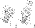
- Fig. 3
- in einer schematischen perspektivischen Ansicht ein Kupplungsteil der Schlauchvorrichtung, das zum Anschluss an einen Stutzen am Ölabscheidergehäuse dient,
- Fig. 4
- in einer schematischen Explosionsdarstellung das Kupplungsteil.
- In den
Fig. 1 bis 4 ist eine Anordnung 1 zum Ableiten von Blow-By-Gasen 5 aus einem nicht dargestellten Kurbelgehäuse eines Verbrennungsmotors gut zu erkennen. Die Blow-By-Gase 5 sind über eine Schlauchvorrichtung 2 einer Frischluftanlage 3 zuführbar. Dargestellt ist hier nur ein Teil eines Abgasturboladergehäuses 4. Die entsprechenden Blow-By-Gase 5 (hier durch entsprechende Pfeile angedeutet) werden ausgehend von einem Ölabscheider 6 durch die Schlauchvorrichtung 2 zu der Verdichterseite des Abgasturboladers geleitet. Von dem Ölabscheider 6 ist hier insbesondere das entsprechende Ölabscheidergehäuse 7 dargestellt. Der Ölabscheider 6 steht in Fluidverbindung mit dem Kurbelgehäuse. Die Schlauchvorrichtung 2 ist einerseits an einem der Frischluftanlage zugeordneten Bauteil 8, nämlich an dem Abgasturboladergehäuse 4 und andererseits an einem mit dem Kurbelgehäuse in Fluidverbindung stehenden Bauteil 9, nämlich hier einem Stutzen 10 angeschlossen. Der Stutzen 10 ist am Ölabscheidergehäuse 7 montiert. Die Schlauchvorrichtung 2 weist nun eine Blow-By-Leitung 11 auf. - Die eingangs genannten Nachteile sind nun dadurch vermieden, dass die Schlauchvorrichtung 2 eine Diagnoseleitung 12 aufweist, wobei über die Diagnoseleitung 12 ein Fehlluftstrom 13 detektierbar, wenn die Schlauchvorrichtung 2 undicht ist, undicht angeschlossen ist oder gar nicht angeschlossen ist. Der Fehlluftstrom 13 ist hier wiederrum durch entsprechende Pfeile angedeutet. Die Diagnoseleitung 12 endet bei korrekter Montierung der Schlauchvorrichtung 2 blind, an einer Stirnseite 14 am Abgasturboladergehäuse 4. Insbesondere ist hierein Dichtring 15 zwischen den Stirnflächen der Mündung der Diagnoseleitung 12 und dem Abgasturboladergehäuse 4 bzw. der Stirnseite 14 angeordnet.
- Die Schlauchvorrichtung 2 weist einen Außenschlauch 16 und einen Innenschlauch 17 auf. Der Innenschlauch 17 dient als Blow-By-Leitung, d.h. im Inneren des Innenschlauchs 17 werden die Blow-By-Gase 5 weitergeleitet. Der Außenschlauch 16 weist einen größeren Durchmesser als der Innenschlauch 17 auf. Zwischen dem Außenschlauch 16 und dem Innenschlauch 17 verbleibt ein Ringraum 18, der einen Teil der Diagnoseleitung 12 bildet.
- Die Schlauchvorrichtung 2 weist nun zwei Kupplungsteile 19, 20 auf. Die Kupplungsteile 19, 20 weisen schlauchseitig, d.h. in Richtung des Außenschlauchs 16 und des Innenschlauchs 17, eine erste Außenumfangsfläche 21 auf, auf die der Innenschlauch 17 aufgesteckt ist. Ferner weisen die Kupplungsteile 19, 20 eine zweite Außenumfangsfläche 22 auf, auf die der Außenschlauch 16 aufgesteckt ist. Zwischen der ersten Außenumfangsfläche 21 und der zweiten Außenumfangsfläche 22 ist mindestens eine Eintrittsöffnung 23, insbesondere sind mehrere Eintrittsöffnungen 23 ausgebildet, die in eine Außenleitung 24 münden. Die Außenleitung 24 bildet einen Teil der Diagnoseleitung 12.
- Die Kupplungsteile 19, 20 sind röhrenförmig ausgebildet und leiten in ihrem Inneren, d.h. in dem entsprechenden zylindrischen Hohlraum 25 die Blow-By-Gase. Der Hohlraum 25 bildet damit einen Teil der Blow-By-Leitung 11. Dieser erste Bereich der Kupplungsteile 19, 20 kann durch ein erstes Bauteil 26 bzw. 27 gebildet sein. Zum Anschluss der Schlauchvorrichtung 2 an die Frischluftanlage 3 bzw. an das Abgasturboladergehäuse 4 ist nun hier ein insbesondere gekröpft ausgebildetes Bauteil 28 vorgesehen, das mit dem Bauteil 27 beispielswiese verschweißt ist oder durch eine Klebeverbindung oder Flügeverbindung verbunden ist. Das Bauteil 28 weist nun einen Kanal 29 für die Blow-By-Gase und einen Kanal 30 auf, der einen Teil der Diagnoseleistung 12 bildet. Der Kanal 30 endet stirnseitig am Abgasturboladergehäuse 4 und ist dort mit dem Dichtring 15 dichtend angeordnet. Der Kanal 30 erstreckt sich etwas weiter in das Abgasturboladergehäuse 4 hinein und ist dort an der Außenumfangsfläche mittels eines Dichtrings 31 abdichtend angeordnet. Ein entsprechend röhrenförmiger Randbereich 32 begrenzt hierbei den Kanal 30. An der Außenumfangsfläche des röhrenförmigen Wandbereichs 32 liegt der Dichtring 31 an.
- Im Folgenden darf nun auf
Fig. 1 undFig. 4 näher eingegangen werden:
Das Bauteil 26 ist mit einem weiteren Bauteil 33 verbunden, in dem die Außenleitung 24 weitergeführt ist. Die Außenleitung 24 tritt hier an einer Außenumfangsfläche 34 aus, die zwischen zwei Ringnuten 35, 36 liegt. In den Ringnuten 35, 36 sind jeweils O-Ringe 37, 38 angeordnet. Die Außenumfangsfläche 34 begrenzt dabei einen Teil eines Ringraumes mit einer Innenumfangsfläche 39 des Stutzens 10. Von der Innenumfangsfläche 39 geht ein Diagnosekanal 40 innerhalb des Bauteils 9 bzw. des entsprechenden Stutzens 10 ab, der wiederrum in einem weiteren Diagnosekanal 41 in das Abgasturboladergehäuse 4 mündet. Die O-Ringe 37, 38 dichten hier den Ringraum zwischen der Außenumfangsfläche 34 gegenüber den entsprechenden anliegenden Innenumfangsflächen des Stutzens 10 ab. - Das Kupplungsteil 19 ist insbesondere mit dem Abgasturboladergehäuse 4 verschraubt. Das Kupplungsteil 20 wird an dem Stutzen 10 mittels einer Rastverbindung verbunden. Dazu weist das Kupplungsteil 20 einen Außenring 42 auf, an dem mindestens eine Rastnase 43 ausgebildet ist. Der Außenring 42 ist über zwei Arme 44 mit dem restlichen Körper verbunden. Wenn nun das Bauteil 9 auf den Stutzen 10 aufgeschoben wird, so werden die Rastnasen 43 über eine Haltekontur 45 am Außenumfang des Stutzens 10 aufgeschoben und rasten dort ein.
-
- 1
- Anordnung
- 2
- Schlauchvorrichtung
- 3
- Frischluftanlage
- 4
- Abgasturboladergehäuse
- 5
- Blow-By-Gase
- 6
- Ölabscheider
- 7
- Ölabscheidergehäuse
- 8
- Bauteil
- 9
- Bauteil
- 10
- Stutzen
- 11
- Blow-By-Leitung
- 12
- Diagnoseleitung
- 13
- Fehlluftstrom
- 14
- Stirnseite
- 15
- Dichtring
- 16
- Außenschlauch
- 17
- Innenschlauch
- 18
- Ringraum
- 19
- Kupplungsteil
- 20
- Kupplungsteil
- 21
- erste Außenumfangsfläche
- 22
- zweite Außenumfangsfläche
- 23
- Eintrittsöffnung
- 24
- Außenleitung
- 25
- Hohlraum
- 26
- Bauteil
- 27
- Bauteil
- 28
- Bauteil
- 29
- Kanal für Blow-By-Gase
- 30
- Kanal
- 31
- Dichtring
- 32
- röhrenförmiger Wandbereich
- 33
- Bauteil
- 34
- Außenumfangsfläche
- 35
- Ringnut
- 36
- Ringnut
- 37
- O-Ring
- 38
- O-Ring
- 39
- Innenumfangsfläche
- 40
- Diagnosekanal
- 41
- Diagnosekanal
- 42
- Außenring
- 43
- Rastnase
- 44
- Arm
- 45
- Haltekontur
Claims (6)
- Anordnung (1) mit einer Frischluftanlage, mit einer Schlauchvorrichtung (2) und mit einem Kurbelgehäuse eines Verbrennungsmotors, zum Ableiten von Blow-By-Gasen (5) aus dem Kurbelgehäuse des Verbrennungsmotors, wobei die Blow-By-Gase (5) über die Schlauchvorrichtung (2) der Frischluftanlage (3) zuführbar sind, wobei die Schlauchvorrichtung (2) einerseits an einem der Frischluftanlage (3) zugeordneten Bauteil (8) und andererseits und an einem mit dem Kurbelgehäuse in Fluidverbindung stehenden Bauteil (9) angeschlossen ist, wobei die Schlauchvorrichtung (2) eine Blow-By-Leitung (11) aufweist, wobei eine Diagnoseleitung (12) vorhanden ist, wobei über die Diagnoseleitung (12) ein Fehlluftstrom (13) detektierbar ist, wenn die Schlauchvorrichtung (2) undicht angeschlossen oder nicht angeschlossen ist, wobei die Schlauchvorrichtung (2) die Diagnoseleitung (12) aufweist, wobei die Schlauchvorrichtung (2) einen Außenschlauch (16) und einen Innenschlauch (17) aufweist, wobei der Innenschlauch (17) als Blow-By-Leitung (11) dient und ein Ringraum (18) zwischen dem Außenschlauch (16) und dem Innenschlauch (17) als Diagnoseleitung (12) dient, wobei die Schlauchvorrichtung (2) mindestens ein Kupplungsteil (19, 20) aufweist, wobei der Innenschlauch (17) an einer ersten Außenumfangsfläche (21) des Kupplungsteils (19, 20) angreift und der Außenschlauch (16) an einer zweiten Außenumfangsfläche (22) des Kupplungsteils (19, 20), wobei eine Eintrittsöffnung (23) in eine Außenleitung (24) im Kupplungsteil (19, 20) mündet, wobei die Außenleitung (24) als Diagnoseleitung (12) dient.
- Anordnung nach Anspruch 1, dadurch gekennzeichnet, dass ein offenes Ende der Diagnoseleitung (12) im korrekt montierten Zustand der Schlauchvorrichtung (2) abdichtend an einem der Bauteile (8, 9) anliegt.
- Anordnung nach Anspruch 2, dadurch gekennzeichnet, dass zwischen einer Stirnseite der Schlauchvorrichtung (2), nämlich um das Ende der Diagnoseleitung (12), und dem Bauteil (8) ein Dichtring (15) angeordnet ist.
- Anordnung nach einem der vorstehenden Ansprüche, dadurch gekennzeichnet, dass die Schlauchvorrichtung (2) einerseits an einem Ölabscheidergehäuse (7) anschließbar ist, wobei das Ölabscheidergehäuse (7) mit einem Saugrohr in Fluidverbindung steht und das Ölabscheidergehäuse (7) einen mit der Diagnoseleitung (12) in Fluidverbindung stehenden Diagnosekanal (41) aufweist.
- Anordnung nach einem der vorstehenden Ansprüche, dadurch gekennzeichnet, dass das Kupplungsteil (19) mittels einer Rastverbindung an einem Stutzen (10) anschließbar ist.
- Anordnung nach dem vorstehenden Anspruch, dadurch gekennzeichnet, dass an einem Außenring (42) des Kupplungsteils (19, 20) mindestens eine Rastnase (43) ausgebildet ist, wobei die mindestens eine Rastnase (43) mit einer an der Außenumfangsfläche des Stutzens (10) ausgebildeten Haltekontur (45) zusammenwirkt.
Applications Claiming Priority (1)
| Application Number | Priority Date | Filing Date | Title |
|---|---|---|---|
| DE102017221735.9A DE102017221735A1 (de) | 2017-12-01 | 2017-12-01 | Anordnung zum Ableiten von Blow-By-Gasen aus einem Kurbelgehäuse eines Verbrennungsmotors |
Publications (2)
| Publication Number | Publication Date |
|---|---|
| EP3492794A1 EP3492794A1 (de) | 2019-06-05 |
| EP3492794B1 true EP3492794B1 (de) | 2021-04-14 |
Family
ID=64453324
Family Applications (1)
| Application Number | Title | Priority Date | Filing Date |
|---|---|---|---|
| EP18207711.5A Active EP3492794B1 (de) | 2017-12-01 | 2018-11-22 | Anordnung zum ableiten von blow-by-gasen aus einem kurbelgehäuse eines verbrennungsmotors |
Country Status (5)
| Country | Link |
|---|---|
| US (1) | US10619535B2 (de) |
| EP (1) | EP3492794B1 (de) |
| KR (1) | KR102160787B1 (de) |
| CN (1) | CN109989803B (de) |
| DE (1) | DE102017221735A1 (de) |
Families Citing this family (3)
| Publication number | Priority date | Publication date | Assignee | Title |
|---|---|---|---|---|
| KR102895782B1 (ko) * | 2020-02-04 | 2025-12-04 | 현대자동차주식회사 | 엔진오일이 니플을 따라 역류하는 것을 방지하는 흡기 구조 및 엔진오일이 니플을 따라 역류하는 것을 방지하는 흡기 구조에 니플을 장착하는 방법 |
| CN111608766A (zh) * | 2020-06-02 | 2020-09-01 | 江阴标榜汽车部件股份有限公司 | 一种双管结构 |
| DE102022208752A1 (de) * | 2022-08-24 | 2024-02-29 | Aft Automotive Gmbh | Fluidkupplung, Verfahren zum Herstellen einer Fluidkupplung sowie Fluidkupplungsanordnung |
Citations (1)
| Publication number | Priority date | Publication date | Assignee | Title |
|---|---|---|---|---|
| DE102016005972A1 (de) * | 2016-05-13 | 2017-02-16 | Daimler Ag | Kurbelgehäuseentlüftung für eine Verbrennungskraftmaschine, insbesondere eines Kraftfahrzeugs |
Family Cites Families (17)
| Publication number | Priority date | Publication date | Assignee | Title |
|---|---|---|---|---|
| FR826980A (fr) * | 1936-10-27 | 1938-04-13 | Deutsche Roehrenwerke Ag | Procédé et dispositif de contrôle de l'étanchéité des bouts de tube et raccords pour tubes et tuyaux |
| GB724288A (en) * | 1951-11-06 | 1955-02-16 | Lang Alfred | Improvements in and relating to a petrol economizing device for internal combustion engines |
| JP3750572B2 (ja) * | 2000-09-25 | 2006-03-01 | 東海ゴム工業株式会社 | バルブ付き接続部材及び接続構造体 |
| US6464520B2 (en) * | 2000-11-16 | 2002-10-15 | Sumitomo Wiring Systems, Ltd. | Connector |
| WO2002103236A1 (en) * | 2001-06-14 | 2002-12-27 | Srock Bryan J | Fluid reclamation device |
| DE10310182B4 (de) * | 2003-03-08 | 2008-11-13 | Audi Ag | Vorrichtung an einer Anschlussverbindung |
| JP2005221348A (ja) * | 2004-02-04 | 2005-08-18 | Laserfront Technologies Inc | リーク検出機能付配管及びリーク検出装置 |
| DE102004063459A1 (de) | 2004-12-23 | 2006-07-06 | Mahle Filtersysteme Gmbh | Brennkraftmaschine mit Frischluftanlage und Entlüftungseinrichtung |
| DE102005030457A1 (de) * | 2005-06-28 | 2007-01-04 | Mahle International Gmbh | Kupplungssystem |
| WO2007024795A1 (en) * | 2005-08-22 | 2007-03-01 | Parker-Hannifin Corporation | Secondarily contained annularly corrugated steel tube pipe and fitting |
| DE102007017668A1 (de) | 2007-04-14 | 2008-10-16 | Bayerische Motoren Werke Aktiengesellschaft | Aufgeladene Brennkraftmaschine und Verfahren zur Überwachung, ob die Kurbelgehäuseentlüftung angeschlossen worden ist |
| DE102007028061A1 (de) * | 2007-06-19 | 2008-12-24 | Fränkische Rohrwerke Gebr. Kirchner GmbH + Co. KG | Kupplungssystem |
| US9140392B2 (en) * | 2013-04-11 | 2015-09-22 | Omega Flex, Inc. | Fitting for tubing containment system |
| JP6285829B2 (ja) * | 2014-09-10 | 2018-02-28 | 株式会社ニフコ | 流体用の配管装置 |
| DE102015009505A1 (de) * | 2015-07-23 | 2017-01-26 | Daimler Ag | Verbrennungskraftmaschine, insbesondere für einen Kraftwagen |
| DE102016015299A1 (de) * | 2016-12-22 | 2018-06-28 | Daimler Ag | Entlüftungsvorrichtung für eine Verbrennungskraftmaschine |
| DE102017002501B4 (de) * | 2017-03-15 | 2020-07-02 | Audi Ag | Brennkraftmaschine mit einer Entlüftungsleitung, Kraftfahrzeug sowie Verfahren zur Überwachung einer Entlüftungsleitung einer Brennkraftmaschine |
-
2017
- 2017-12-01 DE DE102017221735.9A patent/DE102017221735A1/de not_active Withdrawn
-
2018
- 2018-11-22 EP EP18207711.5A patent/EP3492794B1/de active Active
- 2018-11-28 KR KR1020180149230A patent/KR102160787B1/ko active Active
- 2018-12-03 CN CN201811463998.3A patent/CN109989803B/zh active Active
- 2018-12-03 US US16/207,569 patent/US10619535B2/en active Active
Patent Citations (1)
| Publication number | Priority date | Publication date | Assignee | Title |
|---|---|---|---|---|
| DE102016005972A1 (de) * | 2016-05-13 | 2017-02-16 | Daimler Ag | Kurbelgehäuseentlüftung für eine Verbrennungskraftmaschine, insbesondere eines Kraftfahrzeugs |
Also Published As
| Publication number | Publication date |
|---|---|
| EP3492794A1 (de) | 2019-06-05 |
| DE102017221735A1 (de) | 2019-06-06 |
| CN109989803B (zh) | 2021-11-19 |
| KR102160787B1 (ko) | 2020-09-29 |
| US10619535B2 (en) | 2020-04-14 |
| CN109989803A (zh) | 2019-07-09 |
| US20190170032A1 (en) | 2019-06-06 |
| KR20190065135A (ko) | 2019-06-11 |
Similar Documents
| Publication | Publication Date | Title |
|---|---|---|
| DE102013001389B4 (de) | Kurbelgehäuseentlüftung für eine Brennkraftmaschine, Tankentlüftungsleitung und Verbindungssytem hierfür | |
| EP3492794B1 (de) | Anordnung zum ableiten von blow-by-gasen aus einem kurbelgehäuse eines verbrennungsmotors | |
| DE102011118790B4 (de) | Kurbelgehäuseentlüftung für eine Brennkraftmaschine und Verbindungssystem hierfür | |
| EP3756961A2 (de) | Hydraulikleitungskupplung, insbesondere für eine hydraulische bremse oder kupplung lenkergeführter fahrzeuge | |
| DE112006003344B4 (de) | Anschluss für eine Kopplungsvorrichtung für Fluidtransfer | |
| EP3597898A1 (de) | Brennkraftmaschine mit einer in einem fluidführenden, fluidal mit einer tankentlüftungsleitung verbundenen bauteil vorgesehene venturidüse | |
| EP4097384B1 (de) | Anschlussarmatur für eine ventil- und/oder messkupplung für fluidische systeme zur erfassung von fluiddrücken sowie zur befüllung, entleerung und entlüftung fludischer systeme | |
| DE10202349B4 (de) | Kupplung für Füll- und Entlüftungsarbeiten an hydraulischen Systemen | |
| EP2596271A1 (de) | Sicherungseinrichtung für eine verbindungsanordnung | |
| EP2199652B1 (de) | Vorrichtung zum dichten Verbinden und zur Befestigung einer Fluidleitung mit einem anderen fluidführenden Bauteil | |
| DE10310182B4 (de) | Vorrichtung an einer Anschlussverbindung | |
| EP1258624B1 (de) | Ansaugvorrichtung für eine Brennkraftmaschine | |
| EP1756463B1 (de) | Drehdurchführung mit einer gasrückführung | |
| WO2024042039A1 (de) | Fluidkupplung, verfahren zum herstellen einer fluidkupplung sowie fluidkupplungsanordnung | |
| EP3719373B1 (de) | Verbindungsanordnung, vorzugsweise für eine fluidleitung eines fahrzeugs | |
| DE202014007835U1 (de) | Verbrennungsmotor | |
| DE102011122967B3 (de) | Kurbelgehäuseentlüftung für eine Brennkraftmaschine, Kraftstofftankentlüftungsleitung und Verbindungssystem hierfür | |
| DE102016209931A1 (de) | Anordnung zum Sammeln und Abführen von ausgetretenem Kältemittel | |
| DE102016007887A1 (de) | Fluidleitungsanordnung sowie Verfahren zum Betreiben einer Fluidleitungsanordnung | |
| DE19651188C2 (de) | Kraftstoffversorgungseinheit | |
| DE102017217920A1 (de) | Verbindungsanordnung einer ersten fluidführenden Leitung an einer zweiten fluidführenden Leitung, insbesondere eines Kraftfahrzeugs, sowie Verfahren zum Überwachen einer solchen Verbindungsanordnung | |
| EP1077343B2 (de) | Vorrichtung zum Herstellen einer Verbindung zwischen einem Leitungsschlauch und einem weiteren Element | |
| DE202012013363U1 (de) | Steckverbinder zur Verbindung zweier mediumführender Elemente sowie Rohrleitungssystem mit mindestens zwei mediumführenden Elementen | |
| DE102014011509A1 (de) | Tankentlüftungseinrichtung für einen Kraftstofftank | |
| WO1999002907A1 (de) | Rückschlagventil für kupplungsnippel oder fluidleitungen |
Legal Events
| Date | Code | Title | Description |
|---|---|---|---|
| PUAI | Public reference made under article 153(3) epc to a published international application that has entered the european phase |
Free format text: ORIGINAL CODE: 0009012 |
|
| STAA | Information on the status of an ep patent application or granted ep patent |
Free format text: STATUS: THE APPLICATION HAS BEEN PUBLISHED |
|
| AK | Designated contracting states |
Kind code of ref document: A1 Designated state(s): AL AT BE BG CH CY CZ DE DK EE ES FI FR GB GR HR HU IE IS IT LI LT LU LV MC MK MT NL NO PL PT RO RS SE SI SK SM TR |
|
| AX | Request for extension of the european patent |
Extension state: BA ME |
|
| STAA | Information on the status of an ep patent application or granted ep patent |
Free format text: STATUS: REQUEST FOR EXAMINATION WAS MADE |
|
| 17P | Request for examination filed |
Effective date: 20191205 |
|
| RBV | Designated contracting states (corrected) |
Designated state(s): AL AT BE BG CH CY CZ DE DK EE ES FI FR GB GR HR HU IE IS IT LI LT LU LV MC MK MT NL NO PL PT RO RS SE SI SK SM TR |
|
| STAA | Information on the status of an ep patent application or granted ep patent |
Free format text: STATUS: EXAMINATION IS IN PROGRESS |
|
| 17Q | First examination report despatched |
Effective date: 20200123 |
|
| REG | Reference to a national code |
Ref country code: DE Ref legal event code: R079 Ref document number: 502018004787 Country of ref document: DE Free format text: PREVIOUS MAIN CLASS: F16L0039000000 Ipc: F02M0025060000 |
|
| GRAP | Despatch of communication of intention to grant a patent |
Free format text: ORIGINAL CODE: EPIDOSNIGR1 |
|
| STAA | Information on the status of an ep patent application or granted ep patent |
Free format text: STATUS: GRANT OF PATENT IS INTENDED |
|
| RIC1 | Information provided on ipc code assigned before grant |
Ipc: F02D 41/22 20060101ALI20201130BHEP Ipc: F16L 39/00 20060101ALI20201130BHEP Ipc: F01M 11/10 20060101ALI20201130BHEP Ipc: F02M 25/06 20160101AFI20201130BHEP Ipc: F01M 13/04 20060101ALI20201130BHEP Ipc: F16L 39/02 20060101ALI20201130BHEP Ipc: F01M 13/02 20060101ALI20201130BHEP Ipc: F02M 35/10 20060101ALI20201130BHEP |
|
| INTG | Intention to grant announced |
Effective date: 20201223 |
|
| GRAS | Grant fee paid |
Free format text: ORIGINAL CODE: EPIDOSNIGR3 |
|
| GRAA | (expected) grant |
Free format text: ORIGINAL CODE: 0009210 |
|
| STAA | Information on the status of an ep patent application or granted ep patent |
Free format text: STATUS: THE PATENT HAS BEEN GRANTED |
|
| AK | Designated contracting states |
Kind code of ref document: B1 Designated state(s): AL AT BE BG CH CY CZ DE DK EE ES FI FR GB GR HR HU IE IS IT LI LT LU LV MC MK MT NL NO PL PT RO RS SE SI SK SM TR |
|
| REG | Reference to a national code |
Ref country code: GB Ref legal event code: FG4D Free format text: NOT ENGLISH |
|
| REG | Reference to a national code |
Ref country code: CH Ref legal event code: EP |
|
| REG | Reference to a national code |
Ref country code: DE Ref legal event code: R096 Ref document number: 502018004787 Country of ref document: DE |
|
| REG | Reference to a national code |
Ref country code: IE Ref legal event code: FG4D Free format text: LANGUAGE OF EP DOCUMENT: GERMAN |
|
| REG | Reference to a national code |
Ref country code: AT Ref legal event code: REF Ref document number: 1382596 Country of ref document: AT Kind code of ref document: T Effective date: 20210515 |
|
| REG | Reference to a national code |
Ref country code: LT Ref legal event code: MG9D |
|
| REG | Reference to a national code |
Ref country code: NL Ref legal event code: MP Effective date: 20210414 |
|
| PG25 | Lapsed in a contracting state [announced via postgrant information from national office to epo] |
Ref country code: NL Free format text: LAPSE BECAUSE OF FAILURE TO SUBMIT A TRANSLATION OF THE DESCRIPTION OR TO PAY THE FEE WITHIN THE PRESCRIBED TIME-LIMIT Effective date: 20210414 Ref country code: BG Free format text: LAPSE BECAUSE OF FAILURE TO SUBMIT A TRANSLATION OF THE DESCRIPTION OR TO PAY THE FEE WITHIN THE PRESCRIBED TIME-LIMIT Effective date: 20210714 Ref country code: FI Free format text: LAPSE BECAUSE OF FAILURE TO SUBMIT A TRANSLATION OF THE DESCRIPTION OR TO PAY THE FEE WITHIN THE PRESCRIBED TIME-LIMIT Effective date: 20210414 Ref country code: LT Free format text: LAPSE BECAUSE OF FAILURE TO SUBMIT A TRANSLATION OF THE DESCRIPTION OR TO PAY THE FEE WITHIN THE PRESCRIBED TIME-LIMIT Effective date: 20210414 Ref country code: HR Free format text: LAPSE BECAUSE OF FAILURE TO SUBMIT A TRANSLATION OF THE DESCRIPTION OR TO PAY THE FEE WITHIN THE PRESCRIBED TIME-LIMIT Effective date: 20210414 |
|
| PG25 | Lapsed in a contracting state [announced via postgrant information from national office to epo] |
Ref country code: GR Free format text: LAPSE BECAUSE OF FAILURE TO SUBMIT A TRANSLATION OF THE DESCRIPTION OR TO PAY THE FEE WITHIN THE PRESCRIBED TIME-LIMIT Effective date: 20210715 Ref country code: IS Free format text: LAPSE BECAUSE OF FAILURE TO SUBMIT A TRANSLATION OF THE DESCRIPTION OR TO PAY THE FEE WITHIN THE PRESCRIBED TIME-LIMIT Effective date: 20210814 Ref country code: LV Free format text: LAPSE BECAUSE OF FAILURE TO SUBMIT A TRANSLATION OF THE DESCRIPTION OR TO PAY THE FEE WITHIN THE PRESCRIBED TIME-LIMIT Effective date: 20210414 Ref country code: PT Free format text: LAPSE BECAUSE OF FAILURE TO SUBMIT A TRANSLATION OF THE DESCRIPTION OR TO PAY THE FEE WITHIN THE PRESCRIBED TIME-LIMIT Effective date: 20210816 Ref country code: PL Free format text: LAPSE BECAUSE OF FAILURE TO SUBMIT A TRANSLATION OF THE DESCRIPTION OR TO PAY THE FEE WITHIN THE PRESCRIBED TIME-LIMIT Effective date: 20210414 Ref country code: NO Free format text: LAPSE BECAUSE OF FAILURE TO SUBMIT A TRANSLATION OF THE DESCRIPTION OR TO PAY THE FEE WITHIN THE PRESCRIBED TIME-LIMIT Effective date: 20210714 Ref country code: SE Free format text: LAPSE BECAUSE OF FAILURE TO SUBMIT A TRANSLATION OF THE DESCRIPTION OR TO PAY THE FEE WITHIN THE PRESCRIBED TIME-LIMIT Effective date: 20210414 Ref country code: RS Free format text: LAPSE BECAUSE OF FAILURE TO SUBMIT A TRANSLATION OF THE DESCRIPTION OR TO PAY THE FEE WITHIN THE PRESCRIBED TIME-LIMIT Effective date: 20210414 |
|
| REG | Reference to a national code |
Ref country code: DE Ref legal event code: R097 Ref document number: 502018004787 Country of ref document: DE |
|
| PG25 | Lapsed in a contracting state [announced via postgrant information from national office to epo] |
Ref country code: SM Free format text: LAPSE BECAUSE OF FAILURE TO SUBMIT A TRANSLATION OF THE DESCRIPTION OR TO PAY THE FEE WITHIN THE PRESCRIBED TIME-LIMIT Effective date: 20210414 Ref country code: SK Free format text: LAPSE BECAUSE OF FAILURE TO SUBMIT A TRANSLATION OF THE DESCRIPTION OR TO PAY THE FEE WITHIN THE PRESCRIBED TIME-LIMIT Effective date: 20210414 Ref country code: EE Free format text: LAPSE BECAUSE OF FAILURE TO SUBMIT A TRANSLATION OF THE DESCRIPTION OR TO PAY THE FEE WITHIN THE PRESCRIBED TIME-LIMIT Effective date: 20210414 Ref country code: ES Free format text: LAPSE BECAUSE OF FAILURE TO SUBMIT A TRANSLATION OF THE DESCRIPTION OR TO PAY THE FEE WITHIN THE PRESCRIBED TIME-LIMIT Effective date: 20210414 Ref country code: RO Free format text: LAPSE BECAUSE OF FAILURE TO SUBMIT A TRANSLATION OF THE DESCRIPTION OR TO PAY THE FEE WITHIN THE PRESCRIBED TIME-LIMIT Effective date: 20210414 Ref country code: DK Free format text: LAPSE BECAUSE OF FAILURE TO SUBMIT A TRANSLATION OF THE DESCRIPTION OR TO PAY THE FEE WITHIN THE PRESCRIBED TIME-LIMIT Effective date: 20210414 Ref country code: CZ Free format text: LAPSE BECAUSE OF FAILURE TO SUBMIT A TRANSLATION OF THE DESCRIPTION OR TO PAY THE FEE WITHIN THE PRESCRIBED TIME-LIMIT Effective date: 20210414 |
|
| PLBE | No opposition filed within time limit |
Free format text: ORIGINAL CODE: 0009261 |
|
| STAA | Information on the status of an ep patent application or granted ep patent |
Free format text: STATUS: NO OPPOSITION FILED WITHIN TIME LIMIT |
|
| 26N | No opposition filed |
Effective date: 20220117 |
|
| PG25 | Lapsed in a contracting state [announced via postgrant information from national office to epo] |
Ref country code: IS Free format text: LAPSE BECAUSE OF FAILURE TO SUBMIT A TRANSLATION OF THE DESCRIPTION OR TO PAY THE FEE WITHIN THE PRESCRIBED TIME-LIMIT Effective date: 20210814 Ref country code: AL Free format text: LAPSE BECAUSE OF FAILURE TO SUBMIT A TRANSLATION OF THE DESCRIPTION OR TO PAY THE FEE WITHIN THE PRESCRIBED TIME-LIMIT Effective date: 20210414 |
|
| PG25 | Lapsed in a contracting state [announced via postgrant information from national office to epo] |
Ref country code: MC Free format text: LAPSE BECAUSE OF FAILURE TO SUBMIT A TRANSLATION OF THE DESCRIPTION OR TO PAY THE FEE WITHIN THE PRESCRIBED TIME-LIMIT Effective date: 20210414 |
|
| REG | Reference to a national code |
Ref country code: CH Ref legal event code: PL |
|
| PG25 | Lapsed in a contracting state [announced via postgrant information from national office to epo] |
Ref country code: LU Free format text: LAPSE BECAUSE OF NON-PAYMENT OF DUE FEES Effective date: 20211122 Ref country code: IT Free format text: LAPSE BECAUSE OF FAILURE TO SUBMIT A TRANSLATION OF THE DESCRIPTION OR TO PAY THE FEE WITHIN THE PRESCRIBED TIME-LIMIT Effective date: 20210414 Ref country code: BE Free format text: LAPSE BECAUSE OF NON-PAYMENT OF DUE FEES Effective date: 20211130 |
|
| REG | Reference to a national code |
Ref country code: BE Ref legal event code: MM Effective date: 20211130 |
|
| PG25 | Lapsed in a contracting state [announced via postgrant information from national office to epo] |
Ref country code: IE Free format text: LAPSE BECAUSE OF NON-PAYMENT OF DUE FEES Effective date: 20211122 |
|
| P01 | Opt-out of the competence of the unified patent court (upc) registered |
Effective date: 20230523 |
|
| PG25 | Lapsed in a contracting state [announced via postgrant information from national office to epo] |
Ref country code: CY Free format text: LAPSE BECAUSE OF FAILURE TO SUBMIT A TRANSLATION OF THE DESCRIPTION OR TO PAY THE FEE WITHIN THE PRESCRIBED TIME-LIMIT Effective date: 20210414 |
|
| PG25 | Lapsed in a contracting state [announced via postgrant information from national office to epo] |
Ref country code: LI Free format text: LAPSE BECAUSE OF NON-PAYMENT OF DUE FEES Effective date: 20220701 Ref country code: HU Free format text: LAPSE BECAUSE OF FAILURE TO SUBMIT A TRANSLATION OF THE DESCRIPTION OR TO PAY THE FEE WITHIN THE PRESCRIBED TIME-LIMIT; INVALID AB INITIO Effective date: 20181122 Ref country code: CH Free format text: LAPSE BECAUSE OF NON-PAYMENT OF DUE FEES Effective date: 20220701 |
|
| PG25 | Lapsed in a contracting state [announced via postgrant information from national office to epo] |
Ref country code: MK Free format text: LAPSE BECAUSE OF FAILURE TO SUBMIT A TRANSLATION OF THE DESCRIPTION OR TO PAY THE FEE WITHIN THE PRESCRIBED TIME-LIMIT Effective date: 20210414 |
|
| PG25 | Lapsed in a contracting state [announced via postgrant information from national office to epo] |
Ref country code: TR Free format text: LAPSE BECAUSE OF FAILURE TO SUBMIT A TRANSLATION OF THE DESCRIPTION OR TO PAY THE FEE WITHIN THE PRESCRIBED TIME-LIMIT Effective date: 20210414 |
|
| PG25 | Lapsed in a contracting state [announced via postgrant information from national office to epo] |
Ref country code: MT Free format text: LAPSE BECAUSE OF FAILURE TO SUBMIT A TRANSLATION OF THE DESCRIPTION OR TO PAY THE FEE WITHIN THE PRESCRIBED TIME-LIMIT Effective date: 20210414 |
|
| REG | Reference to a national code |
Ref country code: AT Ref legal event code: MM01 Ref document number: 1382596 Country of ref document: AT Kind code of ref document: T Effective date: 20231122 |
|
| PG25 | Lapsed in a contracting state [announced via postgrant information from national office to epo] |
Ref country code: AT Free format text: LAPSE BECAUSE OF NON-PAYMENT OF DUE FEES Effective date: 20231122 |
|
| PG25 | Lapsed in a contracting state [announced via postgrant information from national office to epo] |
Ref country code: AT Free format text: LAPSE BECAUSE OF NON-PAYMENT OF DUE FEES Effective date: 20231122 |
|
| PGFP | Annual fee paid to national office [announced via postgrant information from national office to epo] |
Ref country code: DE Payment date: 20251130 Year of fee payment: 8 |
|
| PGFP | Annual fee paid to national office [announced via postgrant information from national office to epo] |
Ref country code: GB Payment date: 20251125 Year of fee payment: 8 |
|
| PGFP | Annual fee paid to national office [announced via postgrant information from national office to epo] |
Ref country code: FR Payment date: 20251124 Year of fee payment: 8 |
|
| PGFP | Annual fee paid to national office [announced via postgrant information from national office to epo] |
Ref country code: AT Payment date: 20260410 Year of fee payment: 5 |