EP2199652B1 - Vorrichtung zum dichten Verbinden und zur Befestigung einer Fluidleitung mit einem anderen fluidführenden Bauteil - Google Patents
Vorrichtung zum dichten Verbinden und zur Befestigung einer Fluidleitung mit einem anderen fluidführenden Bauteil Download PDFInfo
- Publication number
- EP2199652B1 EP2199652B1 EP20090174840 EP09174840A EP2199652B1 EP 2199652 B1 EP2199652 B1 EP 2199652B1 EP 20090174840 EP20090174840 EP 20090174840 EP 09174840 A EP09174840 A EP 09174840A EP 2199652 B1 EP2199652 B1 EP 2199652B1
- Authority
- EP
- European Patent Office
- Prior art keywords
- receiving sleeve
- receiving
- pipeline
- fluid
- component
- Prior art date
- Legal status (The legal status is an assumption and is not a legal conclusion. Google has not performed a legal analysis and makes no representation as to the accuracy of the status listed.)
- Active
Links
Images

Classifications
-
- F—MECHANICAL ENGINEERING; LIGHTING; HEATING; WEAPONS; BLASTING
- F16—ENGINEERING ELEMENTS AND UNITS; GENERAL MEASURES FOR PRODUCING AND MAINTAINING EFFECTIVE FUNCTIONING OF MACHINES OR INSTALLATIONS; THERMAL INSULATION IN GENERAL
- F16L—PIPES; JOINTS OR FITTINGS FOR PIPES; SUPPORTS FOR PIPES, CABLES OR PROTECTIVE TUBING; MEANS FOR THERMAL INSULATION IN GENERAL
- F16L41/00—Branching pipes; Joining pipes to walls
- F16L41/08—Joining pipes to walls or pipes, the joined pipe axis being perpendicular to the plane of a wall or to the axis of another pipe
- F16L41/086—Joining pipes to walls or pipes, the joined pipe axis being perpendicular to the plane of a wall or to the axis of another pipe fixed with screws
-
- F—MECHANICAL ENGINEERING; LIGHTING; HEATING; WEAPONS; BLASTING
- F16—ENGINEERING ELEMENTS AND UNITS; GENERAL MEASURES FOR PRODUCING AND MAINTAINING EFFECTIVE FUNCTIONING OF MACHINES OR INSTALLATIONS; THERMAL INSULATION IN GENERAL
- F16L—PIPES; JOINTS OR FITTINGS FOR PIPES; SUPPORTS FOR PIPES, CABLES OR PROTECTIVE TUBING; MEANS FOR THERMAL INSULATION IN GENERAL
- F16L37/00—Couplings of the quick-acting type
- F16L37/08—Couplings of the quick-acting type in which the connection between abutting or axially overlapping ends is maintained by locking members
- F16L37/084—Couplings of the quick-acting type in which the connection between abutting or axially overlapping ends is maintained by locking members combined with automatic locking
- F16L37/098—Couplings of the quick-acting type in which the connection between abutting or axially overlapping ends is maintained by locking members combined with automatic locking by means of flexible hooks
- F16L37/0985—Couplings of the quick-acting type in which the connection between abutting or axially overlapping ends is maintained by locking members combined with automatic locking by means of flexible hooks the flexible hook extending radially inwardly from an outer part and engaging a bead, recess or the like on an inner part
Definitions
- the invention relates to a device for tightly connecting and for fastening a fluid line having at least one pipeline to a further fluid-conducting component or unit.
- Fluid lines in motor vehicles run due to the small space in differently curved structures.
- the fluid lines include hoses, tubing and fixed piping.
- the fluid lines have at their ends fastening and connection connections, which are either soldered or molded directly to the ends of the pipes.
- retaining elements must be attached to the pipeline or loosely on the pipeline sit around them, with which the fluid lines are attached to the housing of the component.
- a device for connecting a fluid line to a fluid-carrying component or unit in which a holder for a pipeline is formed as a pipe receiving the clamping plate, which presses by means of a laterally arranged screw on a collar of the pipe and thus the pipeline in a flow bore holds the component.
- connection device for a fluid line in which the fluid line with soldered sealing flange is acted upon axially by a sealing point adjacent, pivotally mounted clamping lever.
- a clamping device To the longer lever arm engages a clamping device, which is loaded by a threaded into the housing of the component or unit axially parallel threaded bolt.
- solder joint restricts the material selection of the connection device to solderable materials. The solder joint must then be protected against corrosion. In addition, the structure of this connection device is very expensive.
- the invention has for its object to provide a device of the type described above, which allows a secure, pressure-tight and easy-to-install connection of fluid lines to other components or units, without the choice of materials is limited to solderable materials.
- the device has a receiving holder which is sealingly inserted with a hollow plug into the flow bore of the component, that the receiving holder has a radial flange with a fastening tab, which contains a laterally offset to the pipeline through hole, through which the receiving holder is attachable to the component, that the receiving holder has the insertion piece coaxially opposite an axially slotted, unilaterally open receiving sleeve whose resulting by the slots locking webs are provided at the front end with radially inwardly directed locking lugs, and that the pipe end to be connected is received sealed in the slotted receiving sleeve with an enlarged diameter having longitudinal portion.
- the invention provides a one-piece receptacle holder for the pipe end, which can be easily mounted on the pipe end.
- the pipe end is simply inserted into the receiving sleeve of the receiving holder.
- the locking webs engage after insertion behind the enlarged diameter in the longitudinal section of the pipe end and hold it in the axial direction positively. It is in this position before axial Move against the plug secured.
- the assembly of the fluid line can thus be carried out easily and positionally reliable.
- the male is inserted into the flow bore of the housing until the mounting tab formed on the female retainer rests against the housing. The installer only has to push the bolt through the hole in the mounting bracket and tighten it in a housing bore.
- the flange of the receiving holder is pressed against the housing and thereby holds the male in its inserted position.
- the receiving holder serves to fix the fluid line, so that the insertion piece can not slip out of the flow bore.
- the length portion is shorter than the inner length of the receiving sleeve, wherein in the free differential space between the end face of the pipe end and the receiving holder, a sealing ring is arranged. In this way, without further machining process, the annular groove receiving the sealing ring is formed between the plug-in socket and the receiving holder.
- the receiving holder made of plastic.
- the connecting device is characterized by housessserpamis and can be produced by injection molding easier.
- the latching lugs are provided at their radially extending ends with inwardly directed inclined contact surfaces. The insertion and locking of the pipe end is facilitated.
- the pipe end to be connected at least in the provided with an enlarged diameter
- Length section has an oval or laterally flattened circular-like cross section, which is positively inserted into a corresponding inner circumference of the receiving sleeve. The two mentioned components are secured against each other against rotation.
- the invention provides a positive and tight connection between a pipe end and a receiving holder of a connecting device, which is characterized by less effort.
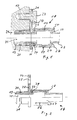
- Connection device shown has a pipe end 12 which is fluidly connected to a further fluid-carrying component 13, wherein the other fluid-carrying component 13 is shown only in a partial section.
- the component 13 may be a fluidic device, such as an oil-lubricated bearing housing for a turbocharger in the motor vehicle.
- the pipe end 12 is made of an aluminum alloy and is a component of a fluid line not shown here.
- the pipe end 12 has at its end an enlarged diameter portion 14, which forms a front and a rear annular shoulder 15 and 16 due to the diameter jump.
- the end of the pipe end 12 runs in the same diameter as in front of the longitudinal section 14 and is the front side in a stepped bore 11 of a flange 20 of a plastic receiving holder 18th
- This receiving holder 18 has on one side or surface of the flange 20 on one side open, hollow cylindrical receiving sleeve 17 which is aligned with the stepped bore 11 of the flange 20.
- the pipe end 12 of the fluid line is inserted into this receiving sleeve 17.
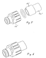
- the pipe end 12 receiving receiving sleeve 17 has axial slots 26 in the circumference ( Fig. 2 ), which cut through the cylinder wall of the receiving sleeve 17. Between the individual slots 26 so individual locking webs 27 are formed ( Fig. 3 ). This locking webs 27 have on their free end face radially inwardly directed locking lugs 28, 29 have the inclined stop surfaces.
- the receiving holder 18 has the receiving sleeve 17 in alignment opposite an insertion piece 19, which is inserted in a flow bore 21 of the fluid-carrying component 13. There, the provided with an axial bore 35 Einsteckstutzen 19 is sealed with a lying in an annular groove 31 O-shaped sealing ring 30 relative to the component 13. The flow bore 21 is aligned with the pipe end 12th
- the receiving holder 18 is fastened by means of a screw 23 to the fluid-carrying component 13.
- the receiving holder 18 at its radial flange 20 a to above radially extending mounting tab 24.
- the attachment by means of the through a through hole 25 of the tab 24 cross-bolt 23 is offset axially parallel to the flow hole 21.
- the axial length between locking lugs 28 and outer surface of the flange 20 is slightly larger than the length of the pipe section 14 with an enlarged diameter.
- the annular shoulder 15 abuts against the inner surface of the locking lugs 28.
- an O-shaped sealing ring 34 is inserted under slight pressure. The sealing ring 34 between the pipe end 12 and receiving holder 18 prevents leakage between these two components.
- connection device From the 3 and 4 the assembly of the connection device becomes apparent. On the front end of the pipe end 12 of the in Fig. 3 between the components shown sealing ring 34 is pushed against the annular shoulder 16. Then the pipe end 12 is pressed against the stop surfaces 29 of the locking lugs 28. The latching webs 27 pivot upward until the longitudinal section 14 is fully inserted into the receiving sleeve 17. Due to the spring-back of the latching webs 27, the latching lugs 28 engage behind the annular shoulder 15, so that the pipe end 12 is secured axially on or in the receiving holder 18 ( Fig. 4 ).
- the thus equipped fluid line is inserted in the final assembly on the motor vehicle with the plug 19 in the flow hole 21 of the component 13 and screwed on the mounting bracket 24.
- Fig. 5 is a further embodiment of the pipe end 12 'and the receiving sleeve 17' shown.
- the pipe end 12 ' has at its end the enlarged diameter portion 14', which is not circular, but has an oval cross-sectional shape or a laterally flattened circular shape.
- the unilaterally open hollow cylindrical receiving sleeve 17 ' has a correspondingly formed, oval inner circumference and allows a positive insertion of the pipe end 12 'in a non-rotating position ( FIG. 6 ).
Landscapes
- Engineering & Computer Science (AREA)
- General Engineering & Computer Science (AREA)
- Mechanical Engineering (AREA)
- Quick-Acting Or Multi-Walled Pipe Joints (AREA)
Description
- Die Erfindung betrifft eine Vorrichtung zum dichten Verbinden und zur Befestigung einer mindestens eine Rohrleitung aufweisenden Fluidleitung an einem weiteren fluidführenden Bauteil oder Aggregat.
- Fluidleitungen in Kraftfahrzeugen verlaufen aufgrund des geringen Bauraumes in unterschiedlich gebogenen Strukturen. Die Fluidleitungen weisen Schläuche, Schlauchleitungen und feste Rohrleitungen auf. Die Fluidleitungen haben an ihren Enden Befestigungs- und Verbindungsanschlüsse, die entweder angelötet oder direkt an die Enden der Rohrleitungen angeformt sind. Zusätzlich müssen Halteelemente an die Rohrleitung angebracht sein oder lose auf der Rohrleitung diese umgreifend sitzen, mit denen die Fluidleitungen an dem Gehäuse des Bauteils befestigt werden.
- Aus der
DE 10 2007 007 370 A1 ist eine Vorrichtung zum Verbinden einer Fluidleitung mit einem fluidführenden Bauteil oder Aggregat bekannt, die alle Merkmale des Oberbegriffs des Anspruchs 1 aufweist. - Aus der
DE 692 15 779 T2 ist eine Vorrichtung zum Verbinden einer Fluidleitung mit einem fluidführenden Bauteil oder Aggregat bekannt, bei der eine Halterung für eine Rohrleitung als eine die Rohrleitung aufnehmende Klemmplatte ausgebildet ist, die mittels einer seitlich angeordneten Verschraubung auf einen Bund der Rohrleitung drückt und damit die Rohrleitung in einer Durchflussbohrung des Bauteils festhält. - Aus der
DE 102 41 921 B3 ist eine Anschlussvorrichtung für eine Fluidleitung bekannt, bei der die Fluidleitung mit angelötetem Dichtflansch durch einen der Dichtstelle benachbarten, schwenkbar gelagerten Klemmhebel axial beaufschlagt wird. An dem längeren Hebelarm greift eine Spanneinrichtung an, die von einem in das Gehäuse des Bauteils oder Aggregates achsparallel geschraubten Gewindebolzen belastbar ist. - Die Lötverbindung beschränkt die Werkstoffauswahl der Anschlussvorrichtung auf lötbare Werkstoffe. Die Lötstelle muss anschließend gegen Korrosion geschützt werden. Zudem ist der Aufbau dieser Anschlussvorrichtung sehr aufwendig.
- Der Erfindung liegt die Aufgabe zugrunde, eine Vorrichtung der eingangs geschilderten Art zu schaffen, die eine sichere, druckdichte und einfach zu montierende Verbindung von Fluidleitungen an anderen Bauteilen oder Aggregaten ermöglicht, ohne dass die Wahl der Werkstoffe auf lötbare Stoffe beschränkt ist.
- Die Aufgabe wird erfindungsgemäß dadurch gelöst, dass die Vorrichtung einen Aufnahmehalter aufweist, der mit einem hohlen Einsteckstutzen dichtend in die Durchflussbohrung des Bauteils einsteckbar ist,
dass der Aufnahmehalter einen radialen Flansch mit einer Befestigungslasche aufweist, die eine seitlich zur Rohrleitung versetzt angeordnete Durchgangsbohrung enthält, über die der Aufnahmehalter an dem Bauteil befestigbar ist,
dass der Aufnahmehalter dem Einsteckstutzen koaxial gegenüberliegend eine axial eingeschlitzte, einseitig offene Aufnahmehülse aufweist, deren durch die Schlitze entstandenen Raststege am stirnseitigen Ende mit radial nach innen gerichteten Rastnasen versehen sind,
und dass das zu verbindende Rohrleitungsende in der geschlitzten Aufnahmehülse mit einem einen vergrößerten Durchmesser aufweisenden Längenabschnitt abgedichtet aufgenommen ist. - Durch die Erfindung wird ein einteiliger Aufnahmehalter für das Rohrende geschaffen, der einfach auf dem Rohrende montierbar ist. Das Rohrende wird einfach in die Aufnahmehülse des Aufnahmehalters gesteckt. Die Raststege greifen nach dem Einschieben hinter den im Durchmesser vergrößerten Längenabschnitt des Rohrendes und halten dieses in axialer Richtung formschlüssig fest. Es ist in dieser Lage vor axialem Verschieben gegenüber dem Einsteckstutzen gesichert. Die Montage der Fluidleitung kann somit einfach und positionssicher durchgeführt werden. Der Einsteckstutzen wird in die Durchflussbohrung des Gehäuses eingeführt, bis die am Aufnahmehalter angeformte Befestigungslasche gegen das Gehäuse anliegt. Der Monteur muss nur noch den Schraubbolzen durch die Bohrung in der Befestigungslasche hindurchstecken und in einer Gehäusebohrung festdrehen.
- Durch das Anziehen des Schraubbolzens wird der Flansch des Aufnahmehalters gegen das Gehäuse gepresst und hält dadurch auch den Einsteckstutzen in seiner eingesteckten Lage. Die Aufnahmehalter dient zum Fixieren der Fluidleitung, so dass der Einsteckstutzen nicht aus der Durchflussbohrung herausrutschen kann.
- Zur dichten Aufnahmen des Rohres werden keine wärmeabgebenden Prozesse wie Löten oder Schweißen notwendig.
- In vorteilhafter Ausgestaltung der Erfindung ist der Längenabschnitt kürzer als die Innenlänge der Aufnahmehülse, wobei in dem freien Differenzraum zwischen Stirnseite des Rohrleitungsendes und dem Aufnahmehalter ein Dichtungsring angeordnet ist. Auf diese Weise wird ohne ein weiteres spanabhebendes Verfahren die den Dichtring aufnehmende Ringnut zwischen Einsteckstutzen und Aufnahmehalter gebildet.
- In weiterer vorteilhafter Ausgestaltung der Erfindung ist der Aufnahmehalter aus Kunststoff. Die Anschlussvorrichtung zeichnet sich dadurch durch Gewichtserpamis aus und lässt sich durch Spritzgießen einfacher herstellen.
- In weiterer vorteilhafter Ausgestaltung der Erfindung sind die Rastnasen an ihren sich radial erstreckenden Enden mit nach innen gerichteten schrägen Anlaufflächen versehen. Das Einschieben und Einrasten des Rohrleitungsendes wird dadurch erleichtert.
- In weiterer vorteilhafter Ausgestaltung der Erfindung weist das zu verbindende Rohrleitungsende zumindest in dem mit einem vergrößerten Durchmesser versehenen
- Längenabschnitt einen ovalen oder seitlich abgeflachten kreisähnlichen Querschnitt aufweist, der formschlüssig in einen entsprechenden Innenumfang der Aufnahmehülse einschiebbar ist. Die beiden genannten Bauteile sind gegeneinander gegen Verdrehen gesichert.
- Durch die Erfindung wird eine formschlüssige und dichte Verbindung zwischen einem Rohrleitungsende und einem Aufnahmehalter einer Anschlussvorrichtung geschaffen, die sich durch geringeren Aufwand auszeichnet.
- Anhand der Zeichnung wird nachstehend ein Beispiel der Erfindung näher erläutert. Es zeigt
- Fig.1
- einen Schnitt durch eine erfindungsgemäße Vorrichtung zum Befestigen und Verbinden einer Fluidleitung an bzw. mit einem fluidführenden Bauteil;
- Fig.2
- einen Halblängsschnitt durch einen Aufnahmehalter mit einem dichtend aufgenommenen Ende der Fluidleitung;
- Fig. 3
- in perspektivischer schematischer Explosionsdarstellung einen Aufnahmehalter der Vorrichtung und das korrespondierend geformte Ende einer Rohrleitung;
- Fig. 4
- zeigt die Bauteile gemäß
Fig. 3 im zusammengesteckten Zustand. - Fig. 5
- zeigt eine modifizierte Ausführungsform der Vorrichtung mit ovalem Querschnitt von Aufnahmehülse und Rohrleitungsende in perspektivischer schematischer Explosionsdarstellung;
- Fig. 6
- zeigt die Bauteile gemäß
Fig. 5 im zusammengesteckten Zustand. - Die in
Fig. 1 gezeigte Anschlussvorrichtung weist ein Rohrleitungsende 12 auf, das mit einem weiteren fluidführenden Bauteil 13 fluidtechnisch verbunden ist, wobei das weitere fluidführende Bauteil 13 nur in einem Teilausschnitt gezeigt ist. Das Bauteil 13 kann eine fluidtechnische Einrichtung, wie z.B. ein ölgeschmiertes Lagergehäuse für einen Turbolader im Kraftfahrzeug, sein. Das Rohrleitungsende 12 ist aus einer Aluminiumlegierung und ist ein Bestandteil einer hier nicht näher gezeigten Fluidleitung. - Das Rohrleitungsende 12 weist endseitig einen im Durchmesser vergrößerten Längenabschnitt 14 auf, der aufgrund des Durchmessersprunges einen vorderen und einen hinteren Ringabsatz 15 bzw. 16 bildet. Endseitig läuft das Rohrleitungsende 12 in gleichem Durchmesser wie vor dem Längenabschnitt 14 aus und liegt stirnseitig in einer Stufenbohrung 11 eines Flansches 20 eines aus Kunststoff bestehenden Aufnahmehalters 18.
- Dieser Aufnahmehalter 18 weist auf der einen Seite bzw. Fläche des Flansches 20 eine einseitig offene, hohlzylindrische Aufnahmehülse 17 auf, die mit der Stufenbohrung 11 des Flansches 20 fluchtet. Das Rohrleitungsende 12 der Fluidleitung ist in diese Aufnahmehülse 17 eingesteckt.
- Die das Rohrleitungsende 12 aufnehmende Aufnahmehülse 17 weist im Umfang axiale Schlitze 26 (
Fig. 2 ) auf, die die Zylinderwand der Aufnahmehülse 17 durchschneiden. Zwischen den einzelnen Schlitzen 26 sind so einzelne Raststege 27 gebildet (Fig. 3 ). Diese Raststege 27 haben an ihrer freien Stirnseite radial nach innen gerichtete Rastnasen 28, die schräge Anlaufflächen 29 aufweisen. - Der Aufnahmehalter 18 weist der Aufnahmehülse 17 fluchtend gegenüberliegend einen Einsteckstutzen 19 auf, der in einer Durchflussbohrung 21 des fluidführenden Bauteils 13 steckt. Dort ist der mit einer Axialbohrung 35 versehene Einsteckstutzen 19 mit einem in einer Ringnut 31 liegenden O-förmigen Dichtungsring 30 gegenüber dem Bauteil 13 abgedichtet. Die Durchflussbohrung 21 fluchtet mit dem Rohrleitungsende 12.
- Der Aufnahmehalter 18 ist mittels einer Schraube 23 an dem fluidführenden Bauteil 13 befestigt. Dazu weist der Aufnahmehalter 18 an seinem radialen Flansch 20 eine sich nach oben radial erstreckende Befestigungslasche 24 auf. Die Befestigung mittels der durch eine Durchgangsbohrung 25 der Lasche 24 greifenden Schraube 23 ist zu der Durchflussbohrung 21 achsparallel versetzt angeordnet.
- Die axiale Länge zwischen Rastnasen 28 und Außenfläche des Flansches 20 ist etwas größer als die Länge des Rohrabschnittes 14 mit vergrößertem Durchmesser. Der Ringabsatz 15 liegt an der Innenfläche der Rastnasen 28 an. In dem sich so bildenden ringförmigen Differenzringraum 33 zwischen dem Ringabsatz 16 des Rohrleitungsendes 12 und der Außenfläche des Flansches 20 ist ein O-förmiger Dichtungsring 34 unter leichter Pressung eingebracht. Der Dichtungsring 34 zwischen Rohrleitungsende 12 und Aufnahmehalter 18 verhindert eine Leckage zwischen diesen beiden Bauteilen.
- Aus den
Fig. 3 und 4 wird der Zusammenbau der Anschlussvorrichtung ersichtlich. Auf das stirnseitige Ende des Rohrleitungsendes 12 wird der inFig. 3 zwischen den Bauteilen dargestellte Dichtungsring 34 gegen den Ringabsatz 16 geschoben. Dann wird das Rohrleitungsende 12 gegen die Anlaufflächen 29 der Rastnasen 28 gedrückt. Die Raststege 27 schwenken nach oben, bis der Längenabschnitt 14 voll in die Aufnahmehülse 17 eingeschoben ist. Durch das Zurückfedern der Raststege 27 fassen die Rastnasen 28 hinter den Ringabsatz 15, so dass das Rohrleitungsende 12 axial gesichert am bzw. im Aufnahmehalter 18 festliegt (Fig. 4 ). - Die so ausgestattete Fluidleitung wird bei der Endmontage am Kraftfahrzeug mit dem Einsteckstutzen 19 in die Durchflussbohrung 21 des Bauteils 13 gesteckt und über die Befestigungslasche 24 angeschraubt.
- In
Fig. 5 ist eine weitere Ausführung des Rohrleitungsendes 12' und der Aufnahmehülse 17' dargestellt. Das Rohrleitungsende 12' weist endseitig den im Durchmesser vergrößerten Längenabschnitt 14' auf, der aber nicht kreisrund ist, sondern eine ovale Querschnittsform oder eine seitlich abgeflachte Kreisform aufweist. Die einseitig offene hohlzylindrische Aufnahmehülse 17' weist einen entsprechend ausgebildeten, ovalen Innenumfang auf und ermöglicht ein formschlüssiges Einschieben des Rohrleitungsendes 12' in eine verdrehsichere Position (Figur 6 ). Durch den so erzielten Formschluss des Rohrleitungsendes 12' in der Aufnahmehülse 17' wird ein Verdrehen der beiden Bauteile 12' und 17' gegeneinander verhindert. -
- 11
- Stufenbohrung
- 12
- Rohrleitungsende
- 13
- fluidführende Bauteil
- 14
- Längenabschnitt
- 15
- Ringabsatz
- 16
- Ringabsatz
- 17
- Aufnahmehülse
- 18
- Aufnahmehalter
- 19
- Einsteckstutzen
- 20
- Flansch
- 21
- Durchflussbohrung
- 23
- Schraube
- 24
- Befestigungslasche
- 25
- Durchgangsbohrung
- 26
- Axiale Schlitze
- 27
- Raststege
- 28
- Rastnasen
- 29
- Anlaufflächen
- 30
- Dichtungsring
- 31
- Ringnut
- 33
- Differenzringraum
- 34
- Dichtungsring
- 35
- Axialbohrung
- 12'
- Rohrleitungsende, oval
- 14'
- Längenabschnitt, oval
- 17'
- Aufnahmehülse, oval
Claims (5)
- Vorrichtung (18) zum Verbinden und zum Befestigen einer mindestens eine Rohrleitung (12) mit einem vergrößerten Durchmesser aufweisenden Längenabschnitt aufweisenden Fluidleitung an einem weiteren fluidführenden Bauteil (13) oder Aggregat,
wobei die Vorrichtung einen Aufnahmehalter (18) aufweist, der einen hohlen Einsteckstutzen (19) aufweist, der dichtend in eine Durchflussbohrung (21) des Bauteils (13) einsteckbar ist,
und wobei der Aufnahmehalter (18) einen radialen Flansch (20) mit einer Befestigungslasche (24) aufweist, die eine seitlich zur zu verbindenden Rohrleitung (12) versetzt angeordnete Durchgangsbohrung (23) enthält, über die Aufnahmehalter (18) an dem Bauteil (13) befestigbar ist,
dadurch gekennzeichnet,
dass der Aufnahmehalter (18) dem Einsteckstutzen (19) koaxial gegenüberliegend eine axial eingeschlitzte, einseitig offene Aufnahmehülse (17) aufweist, deren durch die Schlitze (26) entstandenen Raststege (27) am stirnseitigen Ende mit radial nach innen gerichteten Rastnasen (28) versehen sind, und
dass die geschlitzte Aufnahmehülse (17) derart bemessen ist, dass das zu verbindende Rohrleitungsende (12) in der geschlitzten Aufnahmehülse (17) mit seinem einen vergrößerten Durchmesser aufweisenden Längenabschnitt (14) abgedichtet aufgenommen ist. - Vorrichtung (18) nach Anspruch 1, dadurch gekennzeichnet,
dass in einem freien Differenzraum (33) zwischen Stirnseite des Rohrleitungsendes (12) und dem Aufnahmehalter (18) ein Dichtungsring (34) angeordnet ist,
wobei der freie Differenzraum (33) dadurch gebildet wird, dass der Längenabschnitt (14) kürzer ausgebildet ist als die Innenlänge der Aufnahmehülse (17). - Vorrichtung (18) nach Anspruch 1, dadurch gekennzeichnet,
dass die Vorrichtung (18) aus Kunststoff ist. - Vorrichtung (18) nach Anspruch 1, dadurch gekennzeichnet,
dass die Rastnasen (28) an ihren sich radial erstreckenden Enden mit nach innen gerichteten schrägen Anlaufflächen (29) versehen sind. - Vorrichtung (18) nach Anspruch 1, dadurch gekennzeichnet,
dass die geschlitzte Aufnahmehülse (17') einen ovalen Innenumfang aufweist, der derart bemessen ist, dass das zu verbindende Rohrleitungsende (12'), das zumindest in dem mit einem vergrößerten Durchmesser versehenen Längenabschnitt (14') einen ovalen oder seitlich abgeflachten kreisähnlichen Querschnitt aufweist, formschlüssig in den entsprechenden Innenumfang der Aufnahmehülse (17') einschiebbar ist.
Applications Claiming Priority (1)
| Application Number | Priority Date | Filing Date | Title |
|---|---|---|---|
| DE200810055494 DE102008055494A1 (de) | 2008-12-09 | 2008-12-09 | Vorrichtung zum dichten Verbinden und zur Befestigung einer Fluidleitung mit einem anderen fluidführenden Bauteil |
Publications (2)
| Publication Number | Publication Date |
|---|---|
| EP2199652A1 EP2199652A1 (de) | 2010-06-23 |
| EP2199652B1 true EP2199652B1 (de) | 2014-01-22 |
Family
ID=41650148
Family Applications (1)
| Application Number | Title | Priority Date | Filing Date |
|---|---|---|---|
| EP20090174840 Active EP2199652B1 (de) | 2008-12-09 | 2009-11-03 | Vorrichtung zum dichten Verbinden und zur Befestigung einer Fluidleitung mit einem anderen fluidführenden Bauteil |
Country Status (2)
| Country | Link |
|---|---|
| EP (1) | EP2199652B1 (de) |
| DE (1) | DE102008055494A1 (de) |
Families Citing this family (4)
| Publication number | Priority date | Publication date | Assignee | Title |
|---|---|---|---|---|
| EP2538067B1 (de) * | 2011-06-20 | 2014-10-08 | Delphi International Operations Luxembourg S.à r.l. | Anordnung für ein elektronisch betätigtes Ventil |
| IT202000004567A1 (it) * | 2020-03-04 | 2021-09-04 | Denso Thermal Systems Spa | Gruppo di accoppiamento per un’unità di climatizzazione di un veicolo |
| CN113446109A (zh) * | 2021-07-29 | 2021-09-28 | 福建永强力加动力设备有限公司 | 一种柴油发电机组的外环境降温安装系统 |
| DE102022212051A1 (de) | 2022-06-14 | 2023-12-14 | Continental Automotive Technologies GmbH | Hydraulikaggregat mit einer Anschlussdose für eine Schnellverschluss-Verriegelungseinrichtung |
Family Cites Families (5)
| Publication number | Priority date | Publication date | Assignee | Title |
|---|---|---|---|---|
| US5174612A (en) | 1991-07-15 | 1992-12-29 | Senior Engineering Investments, B.V. | Vibration isolating sealing clamp for conduit structures |
| US6216761B1 (en) * | 1999-03-19 | 2001-04-17 | Linear Products, Inc. | Free turning chilling wheel assembly |
| DE10010529C2 (de) * | 2000-03-03 | 2002-07-04 | Knorr Bremse Systeme | Einrichtung zum lösbaren Verbinden einer Druckmittelleitung mit einem Druckmittelanschluß |
| DE10241921B3 (de) | 2002-09-10 | 2004-01-29 | Eaton Fluid Power Gmbh | Hochdichte Anschlusseinrichtung |
| DE102007007370A1 (de) * | 2007-02-12 | 2008-08-14 | Contitech Techno-Chemie Gmbh | Verbindungsanordnung für Fluidleitungen |
-
2008
- 2008-12-09 DE DE200810055494 patent/DE102008055494A1/de not_active Withdrawn
-
2009
- 2009-11-03 EP EP20090174840 patent/EP2199652B1/de active Active
Also Published As
| Publication number | Publication date |
|---|---|
| EP2199652A1 (de) | 2010-06-23 |
| DE102008055494A1 (de) | 2010-06-17 |
Similar Documents
| Publication | Publication Date | Title |
|---|---|---|
| EP2106515B1 (de) | Verbindungsanordnung für fluidleitungen | |
| EP3173675B1 (de) | Schlauchanschluss | |
| DE3813192A1 (de) | Steckkupplung zum verbinden eines schlauches mit einem rohr | |
| DE69329881T2 (de) | Rohrkupplung | |
| EP2522894A1 (de) | Bajonettverschluss | |
| EP3756961A2 (de) | Hydraulikleitungskupplung, insbesondere für eine hydraulische bremse oder kupplung lenkergeführter fahrzeuge | |
| EP2199652B1 (de) | Vorrichtung zum dichten Verbinden und zur Befestigung einer Fluidleitung mit einem anderen fluidführenden Bauteil | |
| EP0545037B1 (de) | Vorrichtung zum gegenseitigen Verbinden von zwei Leitungen, insbesondere Kraftstoffleitungen | |
| DE102016223355A1 (de) | Verbindungsvorrichtung | |
| EP3724470A1 (de) | Anordnung und verfahren zum verbinden fluidleitender bauteile, insbesondere im abgasstrang eines kraftfahrzeugs | |
| DE102012210342A1 (de) | Schlauchkupplung, insbesondere für hydraulische Hochdruckleitungen eines Ausrücksystems | |
| DE102013113813A1 (de) | Steckverbinder zum Anbinden einer medienführenden Fluidleitung eines Kraftfahrzeugs | |
| DE60306786T2 (de) | Schnellverbindung für einen mit gewinde versehener fluidbauteil | |
| EP2122225B1 (de) | Verbindungsanordnung für fluidleitungen | |
| EP1484544B1 (de) | Leitungsdurchführung für die Installation von einer durch eine Wand hindurchführende Sanitärleitung | |
| AT509729B1 (de) | Verbindungseinheit zum anschluss einer fluidleitung an eine wasserbettmatratze | |
| DE3221518C2 (de) | Fittinge zum automatischen Verbinden von Leitungen in pneumatischen oder hydraulischen Kreisen | |
| DE19838588A1 (de) | Verbindungsschelle einer Rohrverbindung zwischen einem Sammler eines Kraftfahrzeugwärmetauschers und einer äußeren Rohrleitung für das innere Wärmetauschfluid | |
| EP2194307B1 (de) | Anschlussvorrichtung zur Befestigung und zum dichten Verbinden einer Fluidleitung mit einem anderen fluidführenden Bauteil | |
| EP4311969B1 (de) | Steckverbinder zum verbinden von leitungen für flüssige oder gasförmige medien | |
| EP3115671A1 (de) | Transition fitting | |
| DE102012201133B3 (de) | Fitting | |
| DE102008053380A1 (de) | Verbindung | |
| EP3366851A1 (de) | Universal-füllventil-set | |
| WO2011006729A1 (de) | Kupplung mit ausklinkungen |
Legal Events
| Date | Code | Title | Description |
|---|---|---|---|
| PUAI | Public reference made under article 153(3) epc to a published international application that has entered the european phase |
Free format text: ORIGINAL CODE: 0009012 |
|
| AK | Designated contracting states |
Kind code of ref document: A1 Designated state(s): AT BE BG CH CY CZ DE DK EE ES FI FR GB GR HR HU IE IS IT LI LT LU LV MC MK MT NL NO PL PT RO SE SI SK SM TR |
|
| AX | Request for extension of the european patent |
Extension state: AL BA RS |
|
| 17P | Request for examination filed |
Effective date: 20101223 |
|
| 17Q | First examination report despatched |
Effective date: 20110120 |
|
| GRAP | Despatch of communication of intention to grant a patent |
Free format text: ORIGINAL CODE: EPIDOSNIGR1 |
|
| INTG | Intention to grant announced |
Effective date: 20131001 |
|
| GRAS | Grant fee paid |
Free format text: ORIGINAL CODE: EPIDOSNIGR3 |
|
| GRAA | (expected) grant |
Free format text: ORIGINAL CODE: 0009210 |
|
| AK | Designated contracting states |
Kind code of ref document: B1 Designated state(s): AT BE BG CH CY CZ DE DK EE ES FI FR GB GR HR HU IE IS IT LI LT LU LV MC MK MT NL NO PL PT RO SE SI SK SM TR |
|
| REG | Reference to a national code |
Ref country code: GB Ref legal event code: FG4D Free format text: NOT ENGLISH |
|
| REG | Reference to a national code |
Ref country code: CH Ref legal event code: EP |
|
| REG | Reference to a national code |
Ref country code: AT Ref legal event code: REF Ref document number: 650973 Country of ref document: AT Kind code of ref document: T Effective date: 20140215 |
|
| REG | Reference to a national code |
Ref country code: IE Ref legal event code: FG4D Free format text: LANGUAGE OF EP DOCUMENT: GERMAN |
|
| REG | Reference to a national code |
Ref country code: DE Ref legal event code: R096 Ref document number: 502009008736 Country of ref document: DE Effective date: 20140306 |
|
| REG | Reference to a national code |
Ref country code: NL Ref legal event code: VDEP Effective date: 20140122 |
|
| REG | Reference to a national code |
Ref country code: LT Ref legal event code: MG4D |
|
| PG25 | Lapsed in a contracting state [announced via postgrant information from national office to epo] |
Ref country code: LT Free format text: LAPSE BECAUSE OF FAILURE TO SUBMIT A TRANSLATION OF THE DESCRIPTION OR TO PAY THE FEE WITHIN THE PRESCRIBED TIME-LIMIT Effective date: 20140122 Ref country code: NO Free format text: LAPSE BECAUSE OF FAILURE TO SUBMIT A TRANSLATION OF THE DESCRIPTION OR TO PAY THE FEE WITHIN THE PRESCRIBED TIME-LIMIT Effective date: 20140422 Ref country code: IS Free format text: LAPSE BECAUSE OF FAILURE TO SUBMIT A TRANSLATION OF THE DESCRIPTION OR TO PAY THE FEE WITHIN THE PRESCRIBED TIME-LIMIT Effective date: 20140522 |
|
| PG25 | Lapsed in a contracting state [announced via postgrant information from national office to epo] |
Ref country code: ES Free format text: LAPSE BECAUSE OF FAILURE TO SUBMIT A TRANSLATION OF THE DESCRIPTION OR TO PAY THE FEE WITHIN THE PRESCRIBED TIME-LIMIT Effective date: 20140122 Ref country code: CY Free format text: LAPSE BECAUSE OF FAILURE TO SUBMIT A TRANSLATION OF THE DESCRIPTION OR TO PAY THE FEE WITHIN THE PRESCRIBED TIME-LIMIT Effective date: 20140122 Ref country code: NL Free format text: LAPSE BECAUSE OF FAILURE TO SUBMIT A TRANSLATION OF THE DESCRIPTION OR TO PAY THE FEE WITHIN THE PRESCRIBED TIME-LIMIT Effective date: 20140122 Ref country code: PT Free format text: LAPSE BECAUSE OF FAILURE TO SUBMIT A TRANSLATION OF THE DESCRIPTION OR TO PAY THE FEE WITHIN THE PRESCRIBED TIME-LIMIT Effective date: 20140522 Ref country code: SE Free format text: LAPSE BECAUSE OF FAILURE TO SUBMIT A TRANSLATION OF THE DESCRIPTION OR TO PAY THE FEE WITHIN THE PRESCRIBED TIME-LIMIT Effective date: 20140122 Ref country code: FI Free format text: LAPSE BECAUSE OF FAILURE TO SUBMIT A TRANSLATION OF THE DESCRIPTION OR TO PAY THE FEE WITHIN THE PRESCRIBED TIME-LIMIT Effective date: 20140122 |
|
| PG25 | Lapsed in a contracting state [announced via postgrant information from national office to epo] |
Ref country code: LV Free format text: LAPSE BECAUSE OF FAILURE TO SUBMIT A TRANSLATION OF THE DESCRIPTION OR TO PAY THE FEE WITHIN THE PRESCRIBED TIME-LIMIT Effective date: 20140122 Ref country code: HR Free format text: LAPSE BECAUSE OF FAILURE TO SUBMIT A TRANSLATION OF THE DESCRIPTION OR TO PAY THE FEE WITHIN THE PRESCRIBED TIME-LIMIT Effective date: 20140122 |
|
| REG | Reference to a national code |
Ref country code: DE Ref legal event code: R097 Ref document number: 502009008736 Country of ref document: DE |
|
| PG25 | Lapsed in a contracting state [announced via postgrant information from national office to epo] |
Ref country code: RO Free format text: LAPSE BECAUSE OF FAILURE TO SUBMIT A TRANSLATION OF THE DESCRIPTION OR TO PAY THE FEE WITHIN THE PRESCRIBED TIME-LIMIT Effective date: 20140122 Ref country code: DK Free format text: LAPSE BECAUSE OF FAILURE TO SUBMIT A TRANSLATION OF THE DESCRIPTION OR TO PAY THE FEE WITHIN THE PRESCRIBED TIME-LIMIT Effective date: 20140122 Ref country code: EE Free format text: LAPSE BECAUSE OF FAILURE TO SUBMIT A TRANSLATION OF THE DESCRIPTION OR TO PAY THE FEE WITHIN THE PRESCRIBED TIME-LIMIT Effective date: 20140122 Ref country code: CZ Free format text: LAPSE BECAUSE OF FAILURE TO SUBMIT A TRANSLATION OF THE DESCRIPTION OR TO PAY THE FEE WITHIN THE PRESCRIBED TIME-LIMIT Effective date: 20140122 |
|
| PG25 | Lapsed in a contracting state [announced via postgrant information from national office to epo] |
Ref country code: SK Free format text: LAPSE BECAUSE OF FAILURE TO SUBMIT A TRANSLATION OF THE DESCRIPTION OR TO PAY THE FEE WITHIN THE PRESCRIBED TIME-LIMIT Effective date: 20140122 Ref country code: PL Free format text: LAPSE BECAUSE OF FAILURE TO SUBMIT A TRANSLATION OF THE DESCRIPTION OR TO PAY THE FEE WITHIN THE PRESCRIBED TIME-LIMIT Effective date: 20140122 |
|
| PLBE | No opposition filed within time limit |
Free format text: ORIGINAL CODE: 0009261 |
|
| STAA | Information on the status of an ep patent application or granted ep patent |
Free format text: STATUS: NO OPPOSITION FILED WITHIN TIME LIMIT |
|
| 26N | No opposition filed |
Effective date: 20141023 |
|
| REG | Reference to a national code |
Ref country code: DE Ref legal event code: R097 Ref document number: 502009008736 Country of ref document: DE Effective date: 20141023 |
|
| PG25 | Lapsed in a contracting state [announced via postgrant information from national office to epo] |
Ref country code: SI Free format text: LAPSE BECAUSE OF FAILURE TO SUBMIT A TRANSLATION OF THE DESCRIPTION OR TO PAY THE FEE WITHIN THE PRESCRIBED TIME-LIMIT Effective date: 20140122 |
|
| PG25 | Lapsed in a contracting state [announced via postgrant information from national office to epo] |
Ref country code: LU Free format text: LAPSE BECAUSE OF FAILURE TO SUBMIT A TRANSLATION OF THE DESCRIPTION OR TO PAY THE FEE WITHIN THE PRESCRIBED TIME-LIMIT Effective date: 20141103 Ref country code: MC Free format text: LAPSE BECAUSE OF FAILURE TO SUBMIT A TRANSLATION OF THE DESCRIPTION OR TO PAY THE FEE WITHIN THE PRESCRIBED TIME-LIMIT Effective date: 20140122 Ref country code: BE Free format text: LAPSE BECAUSE OF NON-PAYMENT OF DUE FEES Effective date: 20141130 |
|
| REG | Reference to a national code |
Ref country code: CH Ref legal event code: PL |
|
| GBPC | Gb: european patent ceased through non-payment of renewal fee |
Effective date: 20141103 |
|
| PG25 | Lapsed in a contracting state [announced via postgrant information from national office to epo] |
Ref country code: LI Free format text: LAPSE BECAUSE OF NON-PAYMENT OF DUE FEES Effective date: 20141130 Ref country code: CH Free format text: LAPSE BECAUSE OF NON-PAYMENT OF DUE FEES Effective date: 20141130 |
|
| REG | Reference to a national code |
Ref country code: IE Ref legal event code: MM4A |
|
| PG25 | Lapsed in a contracting state [announced via postgrant information from national office to epo] |
Ref country code: GB Free format text: LAPSE BECAUSE OF NON-PAYMENT OF DUE FEES Effective date: 20141103 Ref country code: IE Free format text: LAPSE BECAUSE OF NON-PAYMENT OF DUE FEES Effective date: 20141103 |
|
| REG | Reference to a national code |
Ref country code: FR Ref legal event code: PLFP Year of fee payment: 7 |
|
| REG | Reference to a national code |
Ref country code: AT Ref legal event code: MM01 Ref document number: 650973 Country of ref document: AT Kind code of ref document: T Effective date: 20141103 |
|
| PG25 | Lapsed in a contracting state [announced via postgrant information from national office to epo] |
Ref country code: AT Free format text: LAPSE BECAUSE OF NON-PAYMENT OF DUE FEES Effective date: 20141103 |
|
| PG25 | Lapsed in a contracting state [announced via postgrant information from national office to epo] |
Ref country code: SM Free format text: LAPSE BECAUSE OF FAILURE TO SUBMIT A TRANSLATION OF THE DESCRIPTION OR TO PAY THE FEE WITHIN THE PRESCRIBED TIME-LIMIT Effective date: 20140122 |
|
| PG25 | Lapsed in a contracting state [announced via postgrant information from national office to epo] |
Ref country code: BG Free format text: LAPSE BECAUSE OF FAILURE TO SUBMIT A TRANSLATION OF THE DESCRIPTION OR TO PAY THE FEE WITHIN THE PRESCRIBED TIME-LIMIT Effective date: 20140122 Ref country code: IT Free format text: LAPSE BECAUSE OF FAILURE TO SUBMIT A TRANSLATION OF THE DESCRIPTION OR TO PAY THE FEE WITHIN THE PRESCRIBED TIME-LIMIT Effective date: 20140122 Ref country code: GR Free format text: LAPSE BECAUSE OF FAILURE TO SUBMIT A TRANSLATION OF THE DESCRIPTION OR TO PAY THE FEE WITHIN THE PRESCRIBED TIME-LIMIT Effective date: 20140423 |
|
| PG25 | Lapsed in a contracting state [announced via postgrant information from national office to epo] |
Ref country code: TR Free format text: LAPSE BECAUSE OF FAILURE TO SUBMIT A TRANSLATION OF THE DESCRIPTION OR TO PAY THE FEE WITHIN THE PRESCRIBED TIME-LIMIT Effective date: 20140122 Ref country code: MT Free format text: LAPSE BECAUSE OF FAILURE TO SUBMIT A TRANSLATION OF THE DESCRIPTION OR TO PAY THE FEE WITHIN THE PRESCRIBED TIME-LIMIT Effective date: 20140122 Ref country code: HU Free format text: LAPSE BECAUSE OF FAILURE TO SUBMIT A TRANSLATION OF THE DESCRIPTION OR TO PAY THE FEE WITHIN THE PRESCRIBED TIME-LIMIT; INVALID AB INITIO Effective date: 20091103 |
|
| REG | Reference to a national code |
Ref country code: FR Ref legal event code: PLFP Year of fee payment: 8 |
|
| REG | Reference to a national code |
Ref country code: FR Ref legal event code: PLFP Year of fee payment: 9 |
|
| PG25 | Lapsed in a contracting state [announced via postgrant information from national office to epo] |
Ref country code: MK Free format text: LAPSE BECAUSE OF FAILURE TO SUBMIT A TRANSLATION OF THE DESCRIPTION OR TO PAY THE FEE WITHIN THE PRESCRIBED TIME-LIMIT Effective date: 20140122 |
|
| REG | Reference to a national code |
Ref country code: DE Ref legal event code: R084 Ref document number: 502009008736 Country of ref document: DE |
|
| PGFP | Annual fee paid to national office [announced via postgrant information from national office to epo] |
Ref country code: DE Payment date: 20251130 Year of fee payment: 17 |
|
| PGFP | Annual fee paid to national office [announced via postgrant information from national office to epo] |
Ref country code: FR Payment date: 20251121 Year of fee payment: 17 |