EP2194307B1 - Anschlussvorrichtung zur Befestigung und zum dichten Verbinden einer Fluidleitung mit einem anderen fluidführenden Bauteil - Google Patents
Anschlussvorrichtung zur Befestigung und zum dichten Verbinden einer Fluidleitung mit einem anderen fluidführenden Bauteil Download PDFInfo
- Publication number
- EP2194307B1 EP2194307B1 EP20090174830 EP09174830A EP2194307B1 EP 2194307 B1 EP2194307 B1 EP 2194307B1 EP 20090174830 EP20090174830 EP 20090174830 EP 09174830 A EP09174830 A EP 09174830A EP 2194307 B1 EP2194307 B1 EP 2194307B1
- Authority
- EP
- European Patent Office
- Prior art keywords
- bore
- holding plate
- axial
- apex
- connection
- Prior art date
- Legal status (The legal status is an assumption and is not a legal conclusion. Google has not performed a legal analysis and makes no representation as to the accuracy of the status listed.)
- Active
Links
- 239000012530 fluid Substances 0.000 title claims description 29
- 230000008878 coupling Effects 0.000 title 1
- 238000010168 coupling process Methods 0.000 title 1
- 238000005859 coupling reaction Methods 0.000 title 1
- 238000006073 displacement reaction Methods 0.000 claims description 6
- 230000000284 resting effect Effects 0.000 claims 1
- 238000009434 installation Methods 0.000 description 4
- 239000000446 fuel Substances 0.000 description 2
- 238000007789 sealing Methods 0.000 description 2
- 229910000831 Steel Inorganic materials 0.000 description 1
- 239000003570 air Substances 0.000 description 1
- XAGFODPZIPBFFR-UHFFFAOYSA-N aluminium Chemical compound [Al] XAGFODPZIPBFFR-UHFFFAOYSA-N 0.000 description 1
- 229910052782 aluminium Inorganic materials 0.000 description 1
- 210000003746 feather Anatomy 0.000 description 1
- 230000037431 insertion Effects 0.000 description 1
- 238000003780 insertion Methods 0.000 description 1
- 230000010354 integration Effects 0.000 description 1
- 230000013011 mating Effects 0.000 description 1
- 239000003921 oil Substances 0.000 description 1
- 230000000149 penetrating effect Effects 0.000 description 1
- 239000007787 solid Substances 0.000 description 1
- 239000010959 steel Substances 0.000 description 1
- XLYOFNOQVPJJNP-UHFFFAOYSA-N water Substances O XLYOFNOQVPJJNP-UHFFFAOYSA-N 0.000 description 1
Images

Classifications
-
- F—MECHANICAL ENGINEERING; LIGHTING; HEATING; WEAPONS; BLASTING
- F16—ENGINEERING ELEMENTS AND UNITS; GENERAL MEASURES FOR PRODUCING AND MAINTAINING EFFECTIVE FUNCTIONING OF MACHINES OR INSTALLATIONS; THERMAL INSULATION IN GENERAL
- F16L—PIPES; JOINTS OR FITTINGS FOR PIPES; SUPPORTS FOR PIPES, CABLES OR PROTECTIVE TUBING; MEANS FOR THERMAL INSULATION IN GENERAL
- F16L41/00—Branching pipes; Joining pipes to walls
- F16L41/08—Joining pipes to walls or pipes, the joined pipe axis being perpendicular to the plane of the wall or to the axis of another pipe
- F16L41/086—Joining pipes to walls or pipes, the joined pipe axis being perpendicular to the plane of the wall or to the axis of another pipe fixed with screws
-
- F—MECHANICAL ENGINEERING; LIGHTING; HEATING; WEAPONS; BLASTING
- F16—ENGINEERING ELEMENTS AND UNITS; GENERAL MEASURES FOR PRODUCING AND MAINTAINING EFFECTIVE FUNCTIONING OF MACHINES OR INSTALLATIONS; THERMAL INSULATION IN GENERAL
- F16L—PIPES; JOINTS OR FITTINGS FOR PIPES; SUPPORTS FOR PIPES, CABLES OR PROTECTIVE TUBING; MEANS FOR THERMAL INSULATION IN GENERAL
- F16L23/00—Flanged joints
- F16L23/02—Flanged joints the flanges being connected by members tensioned axially
- F16L23/024—Flanged joints the flanges being connected by members tensioned axially characterised by how the flanges are joined to, or form an extension of, the pipes
Definitions
- the invention relates to a connection device for connecting one end of a fluid line to a component having a flow bore and to be supplied with fluid according to the preamble of claim 1.
- Fluid lines for vehicles have hoses, hose and pipes as well as screw and plug connections. They promote the media air, oil, fuel and water.
- the pipelines of the fluid lines are made of steel, aluminum or solid plastic.
- fluid lines are used for fuel systems from the tank to the engine.
- the application-oriented integration of hoses, pipes and fittings is the basis for functionally reliable fluid lines, which must make absolutely tight connections to all connection units.
- Fluid lines are manufactured as complex modules that are prepared for safe connection to aggregates and components.
- the fluid lines Due to the compact installation spaces in the engine compartments of the vehicles, the fluid lines are configured and bent depending on the available installation space.
- the fluid lines have at their ends plug connections, fittings or other fasteners.
- the connections should be easy to assemble, the dense connection to the most diverse Vietnameseaggregateu must not suffer.
- a connecting device for the end of a pipeline which has a clamping plate with two axially parallel, different sized Bohrgen.
- the smaller hole is in a mounting area and the larger hole in a pipe receiving area of the clamping plate.
- the clamping plate by means of a screw bolt which engages in a threaded bore of the housing of the component to be connected, are attached to this.
- This Gewindebohreng is parallel to a fluid channel of the housing, in which the end of the pipe is inserted. The insertion depth is limited by a radial, outwardly directed annular flange in the end region of the pipeline.
- This annular flange is larger in diameter than the larger, the pipe receiving bore of the pipe receiving area of the clamping plate.
- connection device is cumbersome and time consuming.
- the clamping plate must be pushed onto the pipe.
- the installer must now align the clamping plate to the threaded hole and then insert the bolt through the smaller hole in the mounting area and screw it into the housing.
- the US 5,464,256 relates to a connection device with a plate and an end piece of a hose line to couple the end piece with a fluid circuit.
- the plate has grooves into which the corresponding ribs of the end piece can be inserted in the axial direction, so as to prevent the radial rotation of the plate and tail against each other.
- the invention has for its object to provide a connection device of the type described above, which is characterized by a secure fit of the inserted end of the pipe with a simpler installation.
- the device has a connection piece connected to the end of the fluid line, which can be inserted into the housing bore and that the retaining plate is secured on the connecting piece positively against rotation and axial displacement plugged.
- the positive connection from connecting piece and retaining plate holds both parts relative to each other in secured rotational and axial position.
- the holding plate is placed on the connecting piece under positive locking.
- the retaining plate is preferably clipped onto the connecting piece and is secured in this position against rotation and axial displacement relative to the connecting piece.
- the assembly of the fluid line can thus be carried out easily and positionally reliable.
- the connecting piece is inserted into the housing bore until the holding plate, which is firmly seated on it, bears against the housing in the fastening area. The installer only has to push through the bolt.
- the holding plate does not need to be aligned separately to the pipe
- the holding plate which may also be made of plastic, serves to fix the fluid line, so that the connection piece can not slip out of the flow bore.
- the holding plate at the apex of the first bore on an outstanding latching lug which engages in an axial apex in the connection piece and engages in a locking shoulder in the groove bottom.
- the support plate has in the pipe receiving area a latching nose and a in the apex of the pipe hole inwardly projecting web, which both engage in corresponding recesses of the connecting piece. This prevents twisting and axial displacement.
- the holding plate in the attachment area has a greater thickness than in the region of the pipe or connection piece receiving.
- connecting device 11 is used to connect a pipe 12, which is part of a complex fluid line, to another component or unit 13, which may be a fluid power device, such as an oil-lubricated bearing housing for a turbocharger in the motor vehicle.
- the connection device 11 includes a pipe end 14 of the fluid line and a connection region 15 of the component 13.
- the housing 16 of the unit 13 has a flow bore 17.
- a metallic, hollow cylindrical connecting piece 18 is inserted over a partial length, wherein the periphery of the connecting piece 18 is sealed by an O-shaped sealing ring 19 opposite the flow bore 17.
- the through hole 21 of the connecting piece 18 is formed step-shaped. In the outwardly directed, provided with a larger inner diameter step 22, the pipe end 14 is soldered frontally.
- the pipe end 14 with the connecting piece 18 is part of the pipe 12, which is a part of the complex, not completely shown here fluid line.
- the outer diameter of the hollow cylindrical connecting piece 18 is slightly smaller than the inner diameter of the flow bore 17, in which the connecting piece 18 is inserted.
- the connecting piece 18 is provided at its outer end with a radially outwardly directed annular flange 23.
- a deferred retaining plate 24th On the outside of the flow bore 17 lying circumference of the annular flange 23 is a deferred retaining plate 24th
- the holding plate 24 on the one hand a mounting portion 25 with a bolt hole 26 and on the other hand, a pipe receiving portion 27 with an axially parallel tube hole 28, which the connecting piece 18 in the assembled state ( 4 and 5 ).
- the fastening region 25 of the retaining plate 24 has a stop surface 29, which bears against the housing 16 and whose bolt hole 26 is aligned with a threaded bore 31 of the housing 16.
- the connection device 11 is fastened there to the housing 16 via an engaging screw bolt 32.
- the holding plate 24 has a smaller thickness in the tube receiving region 27 than in the attachment region 25.
- the tube receiving region 27 is provided with a surface 33 recessed relative to the stop surface 29.
- the tube hole 28 penetrating this surface 33 forms circumferentially a circular ring 34, which corresponds to a circumferential recess 35 at the front end of the connecting piece 18 ( Fig. 2 ).
- the annular flange 23 is provided at the apex with an axial groove 36, the bottom 37 has an oblique ramp surface 38 at the beginning.
- the holding plate 24 has in its corresponding vertex of the tube hole 28 in the axial groove 36 mating latch 39.
- the detent 39 protrudes at the apex of the pipe receiving area forming first bore 28 in extension of a projecting from the apex of the bore 28 inwardly, axial web 40 (FIG. Fig. 8 ) from the surface 33 and has an oblique edge 41 on the front side.
- the type of feather key representing axial web 40 engages in the matching axial apex 36 in the connecting piece 18 a.
- the retaining plate 24 is pushed onto the connecting piece 18 before the fluid line is mounted, wherein the retaining plate 24 slides with its latching nose 39 into the axial groove 36 of the connecting piece 24 ( Fig. 3 ).
- the detent 39 slides on the inclined surface 38 up ( Fig. 2 ) and snaps behind the groove bottom 37 and is located at the there formed by a jump on the main diameter of the connecting piece 18 vertical annular surface 42 (FIG. Fig. 7 ) at.
- the holding plate 24 is secured on the connecting piece 18 against rotation and displacement by this positive connection ( Fig. 5 ).
- the holding plate 24 which may be made of plastic, serves to fix the fluid line, so that the connecting piece 18 can not slip out of the flow bore 17.
Landscapes
- Engineering & Computer Science (AREA)
- General Engineering & Computer Science (AREA)
- Mechanical Engineering (AREA)
- Quick-Acting Or Multi-Walled Pipe Joints (AREA)
Description
- Die Erfindung betrifft eine Anschlussvorrichtung zum Verbinden eines Endes einer Fluidleitung mit einem eine Durchflussbohrung aufweisenden, mit Fluid zu versorgendem Bauteil gemäß dem Oberbegriff des Anspruchs 1.
- Fluidleitungen für Fahrzeuge weisen Schläuche, Schlauch- und Rohrleitungen sowie Schraub- und Steckverbindungen auf. Sie fördern die Medien Luft, Öl, Kraftstoff und Wasser. Die Rohrleitungen der Fluidleitungen bestehen aus Stahl, Aluminium oder festem Kunststoff.
- Beispielsweise werden Fluidleitungen für Kraftstoffsysteme vom Tank bis zum Motor eingesetzt. Dabei ist die anwendungsgerechte Einbindung von Schläuchen, Rohren und Armaturen die Basis für funktionssichere Fluidleitungen, die absolut dichte Verbindungen zu allen Anschlussaggregaten herstellen müssen.
- Fluidleitungen werden als komplexe Module hergestellt, die für den sicheren Anschluss an Aggregate und Bauteile vorbereitet sind.
- Aufgrund der kompakten Bauräume in den Motorräumen der Fahrzeuge sind die Fluidleitungen abhängig von dem zur Verfügung stehenden Bauraum konfiguriert und gebogen. Die Fluidleitungen weisen an ihren Enden Steckverbindungen, Verschraubungen oder andere Befestigungselemente auf. Dadurch wird die Montage der Fluidleitungen beim Automobilhersteller ermöglicht. Die Anschlüsse sollen einfach montierbar sein, wobei die dichte Verbindung zu den unterschiedlichsten Fahrzeugaggregateu nicht leiden darf.
- Aus der
DE 692 15 779 T2 (EP 0 523 970 B1 ) ist eine Anschlussvorrichtung für das Ende einer Rohrleitung bekannt, die eine Klemmplatte mit zwei achsparallelen, unterschiedlich großen Bohrengen aufweist. Die kleinere Bohrung liegt in einem Befestigungsbereich und die größere Bohrung in einem Rohraufnahmebereich der Klemmplatte. Über die kleinere Bohrung kann die Klemmplatte mittels eines Schraubbolzens, der in eine Gewindebohrung des Gehäuses des zu verbindenden Bauteils greift, an diesem befestigt werden. Diese Gewindebohreng liegt parallel zu einem Fluidkanal des Gehäuses, in den das Ende der Rohrleitung eingesteckt ist. Die Einstecktiefe ist durch einen radialen, nach außen gerichteten Ringflansch im Endbereich der Rohrleitung begrenzt. Dieser Ringflansch ist im Durchmesser größer als die größere, die Rohrleitung aufnehmende Bohrung des Rohraufnahmebereiches der Klemmplatte. Durch die Befestigung der Klemmplatte über den Schraubbolzen am Gehäuse drückt die Klemmplatte mit dem Rohraufnahmebereich auf den Ringflansch des Rohrendes, das dadurch mit dem Ringflansch dichtend auf die Wand des Gehäuses gedrückt wird. - Die Montage dieser Anschlussvorrichtung ist umständlich und zeitaufwendig. Die Klemmplatte muss auf die Rohrleitung geschoben werden. Der Monteur muss nun die Klemmplatte zur Gewindebohrung ausrichten und dann den Schraubbolzen durch die kleinere Bohrung im Befestigungsbereich stecken und in das Gehäuse eindrehen.
- Die
US 5,464,256 betrifft eine Verbindungsvorrichtung mit einer Platte und einem Endstück einer Schlauchleitung, um das Endstück mit einem Fluidkreislauf zu koppeln. Die Platte weist Nuten auf, in die die korrespondierenden Rippen des Endstückes in axialer Richtung eingeführt werden können, um so die radiale Verdrehung von Platte und Endstück gegeneinander zu verhindern. - Der Erfindung liegt die Aufgabe zugrunde, eine Anschlussvorrichtung der eingangs geschilderten Art zu schaffen, die sich bei einfacherer Montage durch einen sicheren Sitz des eingesteckten Endes der Rohrleitung auszeichnet.
- Die Aufgabe wird erfindungsgemäß dadurch gelöst, dass die Vorrichtung einen mit dem Ende der Fluidleitung verbundenen Anschlussstutzen aufweist, der in die Gehäusebohrung einsteckbar ist und dass die Halteplatte auf dem Anschlussstutzen formschlüssig gegen Drehung and Axialverschiebung gesichert aufsteckbar ist. Die formschlüssige Verbindung von Anschlussstutzen und Halteplatte hält beide Teile relativ zueinander in gesicherter Rotations- und Axiallage.
- Gemäß der Erfindung wird die Halteplatte auf den Anschlussstutzen unter Formschluss aufgesetzt. Die Halteplatte wird auf den Anschlussstutzen vorzugsweise aufgeklipst und ist in dieser Lage vor Verdrehen und axialem Verschieben gegenüber dem Anschlussstutzen gesichert. Die Montage der Fluidleitung kann somit einfach und positionssicher durchgeführt werden. Der Anschlussstutzen wird in die Gehäusebohrung eingeführt, bis die auf ihm festsitzende Halteplatte im Befestigungsbereich gegen das Gehäuse anliegt. Der Monteur muss nur noch den Schraubbolzen durchstecken. Die Halteplatte braucht nicht separat zur Rohrleitung ausgerichtet zu werden
- Durch das Anziehen des Schraubbolzens wird die Halteplatte gegen das Gehäuse gepresst und hält dadurch auch den Anschlussstutzen in seiner eingesteckten Lage. Die Halteplatte, die auch aus Kunststoff hergestellt sein kann, dient zum Fixieren der Fluidleitung, so dass der Anschlussstutzen nicht aus der Durchflussbohrung herausrutschen kann.
- In vorteilhafter Ausgestaltung der Erfindung weist die Halteplatte im Scheitelpunkt der ersten Bohrung eine hervorragende Rastnase auf, die in eine axiale Scheitelnut im Anschlussstutzen eingreift und in einen Verriegelungsabsatz im Nutgrund eingreift.
- Die Halteplatte hat im Rohraufnahmebereich eine Rastnase und einen im Scheitelpunkt des Rohrlochs nach innen ragenden Steg, die beide in entsprechende Ausnehmungen des Anschlussstutzens eingreifen. Dadurch werden ein Verdrehen und ein axiales Verschieben verhindert.
- In weiterer Ausgestaltung der Erfindung weist die Halteplatte im Befestigungsbereich eine größere Dicke auf als im Bereich der Rohr- bzw. Anschlussstutzenaufnahme.
- Anhand der Zeichnung wird nachstehend ein Ausführungsbeispiel der Erfindung näher erläutert. Es zeigt
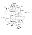
- Fig. 1
- die Anschlussvorrichtung im Längsschnitt mit einer an einem Gehäuse befestigten Halteplatte zum Befestigen und Verbinden des Endes einer Fluidleitung;
- Fig. 2
- die Halteplatte und den Anschlussstutzen des Rohrleitungsendes in geschnittener Detaildarstellung im unverriegelten Zustand zueinander;
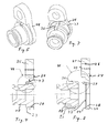
- Fig. 3
- Halteplatte und Anschlussstutzen in perspektivischer Ansicht vor dem Ineinanderstecken;
- Fig. 4
- Halteplatte und Anschlussstutzen im miteinander verriegelten Zustand;
- Fig. 5
- die verriegelten Bauteile in perspektivischer Ansicht;
- Fig. 6
- eine Detaildarstellung aus
Fig. 2 ; - Fig. 7
- eine Detaildarstellung aus
Fig. 4 . - Fig. 8
- eine Rückansicht der Halteplatte.
- Die in
Fig. 1 gezeigte Anschlussvorrichtung 11 dient zum Anschließen einer Rohrleitung 12, die Bestandteil einer komplexen Fluidleitung ist, an ein anderes Bauteil bzw. Aggregat 13, das eine fluidtechnische Einrichtung, wie z.B. ein ölgeschmiertes Lagergehäuse für einen Turbolader im Kraftfahrzeug, sein kann. Zu der Anschlussvorrichtung 11 gehört ein Rohrleitungsende 14 der Fluidleitung und ein Anschlussbereich 15 des Bauteils 13. - Das Gehäuse 16 des Aggregates 13 weist eine Durchflussbohrung 17 auf. In diese Durchflussbohrung 17 ist ein metallischer, hohlzylindrischer Anschlussstutzen 18 über eine Teillänge eingesteckt, wobei der Umfang des Anschlussstutzens 18 über einen O-förmigen Dichtungsring 19 gegenüber der Durchflussbohrung 17 abgedichtet ist.
- Die Durchgangsbohrung 21 des Anschlussstutzens 18 ist stufenförmig ausgebildet. In der nach außen gerichteten, mit größerem Innendurchmesser versehenen Stufe 22 ist das Rohrleitungsende 14 stirnseitig eingelötet. Das Rohrleitungsende 14 mit dem Anschlussstutzen 18 ist Teil der Rohrleitung 12, die ein Bestandteil der komplexen, hier nicht vollständig gezeigten Fluidleitung ist.
- Der Außendurchmesser des hohlzylindrischen Anschlussstutzens 18 ist geringfügig kleiner als der Innendurchmesser der Durchflussbohrung 17, in die der Anschlussstutzen 18 eingesteckt ist. Der Anschlussstutzen 18 ist an seinem außenliegenden Ende mit einem radial nach außen gerichteten Ringflansch 23 versehen. Auf dem außerhalb der Durchflussbohrung 17 liegenden Umfang des Ringflansches 23 sitzt eine aufgeschobene Halteplatte 24.
- Wie auch aus der der
Fig. 2 ersichtlich ist, weist die Halteplatte 24 einerseits einen Befestigungsbereich 25 mit einem Bolzenloch 26 und andererseits einen Rohraufnahmebereich 27 mit einem achsparallelen Rohrloch 28 auf, das den Anschlussstutzen 18 im montierten Zustand (Fig. 4 und 5 ) aufnimmt. Der Befestigungsbereich 25 der Halteplatte 24 weist eine Anschlagfläche 29 auf, die an dem Gehäuse 16 anliegt und deren Bolzenloch 26 mit einer Gewindebohrung 31 des Gehäuses 16 fluchtet. Die Anschlussvorrichtung 11 wird dort über einen eingreifenden Schraubbolzen 32 an dem Gehäuse 16 befestigt. - Die Halteplatte 24 weist im Rohraufnahmebereich 27 eine geringere Dicke auf als im Befestigungsbereich 25. Dadurch ist der Rohraufnahmebereich 27 mit einer gegenüber der Anschlagfläche 29 zurückgesetzten Fläche 33 versehen. Das diese Fläche 33 durchdringende Rohrloch 28 bildet umfangsmäßig einen Kreisring 34, der mit einer umfangsmäßigen Eindrehung 35 am stirnseitigen Ende des Anschlussstutzens 18 korrespondiert (
Fig. 2 ). - Wie aus
Fig. 2 undFig. 6 ersichtlich ist, ist der Ringflansch 23 am Scheitelpunkt mit einer Axialnut 36 versehen, deren Boden 37 zu Beginn eine schräge Anlauffläche 38 aufweist. Die Halteplatte 24 weist in ihrem korrespondierenden Scheitelpunkt des Rohrloches 28 eine in die Axialnut 36 passende Rastnase 39 auf. Die Rastnase 39 ragt im Scheitelpunkt der den Rohraufnahmebereich bildenden ersten Bohrung 28 in Verlängerung eines von einem im Scheitelpunkt der Bohrung 28 nach innen ragenden, axialen Steg 40 (Fig. 8 ) von der Fläche 33 vor und weist stirnseitig eine schräge Anlaufkante 41 auf. Der eine Art Paßfeder darstellende axiale Steg 40 greift in die passende axiale Scheitelnut 36 im Anschlussstutzen 18 ein. - Die Halteplatte 24 wird vor der Montage der Fluidleitung auf den Anschlussstutzen 18 geschoben, wobei die Halteplatte 24 mit ihrer Rastnase 39 in die axiale Nut 36 des Anschlussstutzens 24 gleitet (
Fig. 3 ). Die Rastnase 39 gleitet an der schrägen Fläche 38 hoch (Fig. 2 ) und rastet hinter dem Nutboden 37 ein und liegt an der dort durch einen Sprung auf den Hauptdurchmesser des Anschlussstutzens 18 gebildeten senkrechten Ringfläche 42 (Fig. 7 ) an. - Durch das Einrasten wird ein axiales Verschieben der beiden Bauteile 18 und 24 zueinander verhindert. Die Rastnase 39 und der Kreisring 34 der Halteplatte 24 sichern den Anschlussstutzen 18 in axialer Richtung. Die Sicherung gegen eine Rotation wird durch die senkrechten Wände der Axialnut 36 erzielt, in der die Rastnase 39 und der axiale Steg 40 mit ihren Seiten anliegen.
- Die Halteplatte 24 ist auf dem Anschlussstutzen 18 gegen Verdrehung und Verschiebung durch diese formschlüssige Verbindung gesichert (
Fig. 5 ). - Durch das Anziehen des Schraubbolzens 32 wird die Anschlagfläche 29 der Halteplatte 24 gegen das Gehäuse 11 gepresst (
Fig. 1 ) und hält dadurch auch den Anschlussstutzen 18 in seiner eingesteckten Lage. Die Halteplatte 24, die aus Kunststoff hergestellt sein kann, dient zum Fixieren der Fluidleitung, so dass der Anschlussstutzen 18 nicht aus der Durchflussbohrung 17 herausrutschen kann. -
- 11
- Anschlussvorrichtung
- 12
- Rohrleitung
- 13
- Bauteil; Aggregat
- 14
- Rohrleitungsende
- 15
- Anschlussbereich
- 16
- Gehäuse
- 17
- Durchflussbohrung
- 18
- Anschlussstutzen
- 19
- Dichtungsring
- 21
- Durchgangsbohrung
- 22
- Stufe
- 23
- Ringflansch
- 24
- Halteplatte
- 25
- Befestigungsbereich
- 26
- Bolzenloch
- 27
- Rohraufnahmebereich
- 28
- Rohrloch
- 29
- Anschlagfläche
- 31
- Gewindebohrung
- 32
- Schraubbolzen
- 33
- Fläche
- 34
- Kreisring
- 35
- Eindrehung
- 36
- Axialnut
- 37
- Nutboden
- 38
- schräge Anlauffläche
- 39
- Rastnase
- 40
- axialer Steg
- 41
- Anlaufkante
- 42
- Ringfläche
Claims (4)
- Anschlussvorrichtung (11) zum Verbinden eines Endes (14) einer Fluidleitung (12) mit einem eine Durchflussbohrung (17) aufweisenden, mit Fluid zu versorgenden Aggregates (13), insbesondere eines Kraftfahrzeugaggregates,
mit einer zwei seitlich zueinander versetzte Bohrungen (26, 28) aufweisenden Halteplatte (24), die das Ende (14) der in die Durchflussbohrung (17) einsteckbaren Fluidleitung (12) in einer ersten Bohrung (28) umfasst und über die zweite Bohrung (26) am Aggregat (13) befestigbar ist,
mit einem an dem Ende (14) der Fluidleitung (12) angeordneten, nach außen gerichteten Ringflansch (23), der eine ringförmige Druckfläche bildet, gegen die der Rohraufnahmebereich (27) der Halteplatte (24) anliegt, und
mit einem mit dem Ende (14) der Fluidleitung (12) verbundenen Anschlussstutzen (18), der in die Durchflussbohrung (17) einsteckbar ist,
wobei die Halteplatte (24) auf dem Anschlussstutzen (18) formschlüssig gegen Drehung und Axialverschiebung gesichert aufsteckbar ist,
dadurch gekennzeichnet,
dass die Halteplatte (24) im Scheitelpunkt der ersten Bohrung (28) eine hervorragende Rastnase (39) aufweist, die in einer axialen Scheitelnut (36) im Anschlussstutzen (18) liegt und in einen Verriegelungsabsatz (42) im Nutgrund (37) eingreift. - Vorrichtung (11) nach Anspruch 1, dadurch gekennzeichnet, dass die formschlüssige Verbindung von Anschlussstutzen (18) und Halteplatte (24) beide Teile (18, 24) relativ zueinander in gesicherter Rotations- und Axiallage hält.
- Vorrichtung (11) nach einem der Ansprüche 1 oder 2, dadurch gekennzeichnet, dass die Halteplatte (24) im Scheitelpunkt der den Rohraufnahmebereich bildenden ersten Bohrung (28) einen im Scheitelpunkt der Bohrung (28) nach innen ragenden, axialen Steg, aufweist, der in eine axiale Scheitelnut (36) im Anschlussstutzen (18) eingreift.
- Vorrichtung (11) nach Anspruch 1, dadurch gekennzeichnet, dass die Halteplatte (24) im Befestigungsbereich (25) eine größere Dicke aufweist als im Rohraufnahmebereich (27).
Applications Claiming Priority (1)
| Application Number | Priority Date | Filing Date | Title |
|---|---|---|---|
| DE102008055470A DE102008055470A1 (de) | 2008-12-02 | 2008-12-02 | Anschlussvorrichtung zur Befestigung und zum dichten Verbinden einer Fluidleitung mit einem anderen fluidführenden Bauteil |
Publications (2)
| Publication Number | Publication Date |
|---|---|
| EP2194307A1 EP2194307A1 (de) | 2010-06-09 |
| EP2194307B1 true EP2194307B1 (de) | 2012-10-10 |
Family
ID=41331461
Family Applications (1)
| Application Number | Title | Priority Date | Filing Date |
|---|---|---|---|
| EP20090174830 Active EP2194307B1 (de) | 2008-12-02 | 2009-11-03 | Anschlussvorrichtung zur Befestigung und zum dichten Verbinden einer Fluidleitung mit einem anderen fluidführenden Bauteil |
Country Status (2)
| Country | Link |
|---|---|
| EP (1) | EP2194307B1 (de) |
| DE (1) | DE102008055470A1 (de) |
Family Cites Families (7)
| Publication number | Priority date | Publication date | Assignee | Title |
|---|---|---|---|---|
| JPH0435246Y2 (de) * | 1986-09-29 | 1992-08-20 | ||
| US5174612A (en) | 1991-07-15 | 1992-12-29 | Senior Engineering Investments, B.V. | Vibration isolating sealing clamp for conduit structures |
| FR2694797B1 (fr) | 1992-08-12 | 1994-11-04 | Hutchinson | Platine et embout pour dispositif de raccordement, dispositif de raccordement et son procédé de réalisation. |
| US6216761B1 (en) * | 1999-03-19 | 2001-04-17 | Linear Products, Inc. | Free turning chilling wheel assembly |
| US6318765B1 (en) * | 1999-10-29 | 2001-11-20 | Automotive Fluid Systems, Inc. | Serviceable mounting device for conduit |
| US6942255B2 (en) * | 2002-04-23 | 2005-09-13 | Q3Jmc, Inc. | Twist fitting for air tank connections |
| DE102004036719A1 (de) * | 2003-08-07 | 2005-03-17 | Denso Corp., Kariya | Rohrverbindungskonstruktion und Herstellungsverfahren dafür |
-
2008
- 2008-12-02 DE DE102008055470A patent/DE102008055470A1/de not_active Withdrawn
-
2009
- 2009-11-03 EP EP20090174830 patent/EP2194307B1/de active Active
Also Published As
| Publication number | Publication date |
|---|---|
| EP2194307A1 (de) | 2010-06-09 |
| DE102008055470A1 (de) | 2010-07-01 |
Similar Documents
| Publication | Publication Date | Title |
|---|---|---|
| DE102004032572B4 (de) | Verbindungsanordnung mit Kontaktstift | |
| DE102005044304A1 (de) | Anschlussanordnung zum Anschließen einer Rohrleitung an ein System | |
| WO2008077677A1 (de) | Verbindungsanordnung für fluidleitungen | |
| WO2019115390A1 (de) | Anordnung und verfahren zum verbinden fluidleitender bauteile, insbesondere im abgasstrang eines kraftfahrzeugs | |
| EP3854618B1 (de) | Kraftstofftank umfassend ein verbindungsstück | |
| EP2199652B1 (de) | Vorrichtung zum dichten Verbinden und zur Befestigung einer Fluidleitung mit einem anderen fluidführenden Bauteil | |
| DE102013113813A1 (de) | Steckverbinder zum Anbinden einer medienführenden Fluidleitung eines Kraftfahrzeugs | |
| EP2133615B1 (de) | Kupplungseinrichtung, insbesondere für eine Frischluftanlage | |
| DE102012010647A1 (de) | Anschlussfitting | |
| EP2194307B1 (de) | Anschlussvorrichtung zur Befestigung und zum dichten Verbinden einer Fluidleitung mit einem anderen fluidführenden Bauteil | |
| DE19927431A1 (de) | Anschluß mit einem an einer Leitung stoffschlüssig befestigten Stecker | |
| DE102007019332A1 (de) | Anschlusselement für Fluidleitungen sowie Druckfluid führendes Bauelement | |
| DE102007007370A1 (de) | Verbindungsanordnung für Fluidleitungen | |
| DE19808315A1 (de) | Nehmerzylinder mit einem Druckstutzen, an den ein Adapter anschließbar ist, der durch eine Öffnung des Kupplungsgehäuses einführbar ist | |
| DE60306786T2 (de) | Schnellverbindung für einen mit gewinde versehener fluidbauteil | |
| EP1751462B1 (de) | Lösbare ladeluft-kupplungsmuffe | |
| EP1258624B1 (de) | Ansaugvorrichtung für eine Brennkraftmaschine | |
| WO2020120184A1 (de) | Dichtungsanordnung, dichtmuffe und deren verwendung | |
| EP2910792A1 (de) | Verbindungseinrichtung für die fluidische verbindung eines fluidrohrabschnitts mit einem weiteren fluidrohrabschnitt | |
| EP1602872A2 (de) | System aus Ventil und Schutzkappe | |
| DE102021110130B4 (de) | Anschlussvorrichtung zum Anschluss einer Wasserpumpe an eine Ölpumpe einer Brennkraftmaschine und Verfahren zur Montage einer Wasserpumpe an einer Ölpumpe einer Brennkraftmaschine | |
| DE102017212907A1 (de) | Flexibles Kupplungselement mit Toleranzausgleich zur flexiblen Verbindung zweier medienführender Elemente | |
| DE102008053380A1 (de) | Verbindung | |
| DE102006014708A1 (de) | Leitungsverbindung für Fluidleitungen, insbesondere für CO2-führende Fluidleitungen in einer Fahrzeugklimaanlage | |
| DE19912351A1 (de) | Zur Befestigung an einem Anschlußstutzen vorgesehenes Anschlußstück |
Legal Events
| Date | Code | Title | Description |
|---|---|---|---|
| PUAI | Public reference made under article 153(3) epc to a published international application that has entered the european phase |
Free format text: ORIGINAL CODE: 0009012 |
|
| AK | Designated contracting states |
Kind code of ref document: A1 Designated state(s): AT BE BG CH CY CZ DE DK EE ES FI FR GB GR HR HU IE IS IT LI LT LU LV MC MK MT NL NO PL PT RO SE SI SK SM TR |
|
| AX | Request for extension of the european patent |
Extension state: AL BA RS |
|
| 17P | Request for examination filed |
Effective date: 20101209 |
|
| 17Q | First examination report despatched |
Effective date: 20110208 |
|
| GRAP | Despatch of communication of intention to grant a patent |
Free format text: ORIGINAL CODE: EPIDOSNIGR1 |
|
| GRAS | Grant fee paid |
Free format text: ORIGINAL CODE: EPIDOSNIGR3 |
|
| GRAA | (expected) grant |
Free format text: ORIGINAL CODE: 0009210 |
|
| AK | Designated contracting states |
Kind code of ref document: B1 Designated state(s): AT BE BG CH CY CZ DE DK EE ES FI FR GB GR HR HU IE IS IT LI LT LU LV MC MK MT NL NO PL PT RO SE SI SK SM TR |
|
| REG | Reference to a national code |
Ref country code: GB Ref legal event code: FG4D Free format text: NOT ENGLISH |
|
| REG | Reference to a national code |
Ref country code: AT Ref legal event code: REF Ref document number: 579128 Country of ref document: AT Kind code of ref document: T Effective date: 20121015 Ref country code: CH Ref legal event code: EP |
|
| REG | Reference to a national code |
Ref country code: IE Ref legal event code: FG4D Free format text: LANGUAGE OF EP DOCUMENT: GERMAN |
|
| REG | Reference to a national code |
Ref country code: DE Ref legal event code: R096 Ref document number: 502009005023 Country of ref document: DE Effective date: 20121206 |
|
| PG25 | Lapsed in a contracting state [announced via postgrant information from national office to epo] |
Ref country code: SI Free format text: LAPSE BECAUSE OF FAILURE TO SUBMIT A TRANSLATION OF THE DESCRIPTION OR TO PAY THE FEE WITHIN THE PRESCRIBED TIME-LIMIT Effective date: 20121010 |
|
| REG | Reference to a national code |
Ref country code: NL Ref legal event code: VDEP Effective date: 20121010 |
|
| REG | Reference to a national code |
Ref country code: LT Ref legal event code: MG4D |
|
| PG25 | Lapsed in a contracting state [announced via postgrant information from national office to epo] |
Ref country code: ES Free format text: LAPSE BECAUSE OF FAILURE TO SUBMIT A TRANSLATION OF THE DESCRIPTION OR TO PAY THE FEE WITHIN THE PRESCRIBED TIME-LIMIT Effective date: 20130121 Ref country code: LT Free format text: LAPSE BECAUSE OF FAILURE TO SUBMIT A TRANSLATION OF THE DESCRIPTION OR TO PAY THE FEE WITHIN THE PRESCRIBED TIME-LIMIT Effective date: 20121010 Ref country code: SE Free format text: LAPSE BECAUSE OF FAILURE TO SUBMIT A TRANSLATION OF THE DESCRIPTION OR TO PAY THE FEE WITHIN THE PRESCRIBED TIME-LIMIT Effective date: 20121010 Ref country code: HR Free format text: LAPSE BECAUSE OF FAILURE TO SUBMIT A TRANSLATION OF THE DESCRIPTION OR TO PAY THE FEE WITHIN THE PRESCRIBED TIME-LIMIT Effective date: 20121010 Ref country code: NL Free format text: LAPSE BECAUSE OF FAILURE TO SUBMIT A TRANSLATION OF THE DESCRIPTION OR TO PAY THE FEE WITHIN THE PRESCRIBED TIME-LIMIT Effective date: 20121010 Ref country code: NO Free format text: LAPSE BECAUSE OF FAILURE TO SUBMIT A TRANSLATION OF THE DESCRIPTION OR TO PAY THE FEE WITHIN THE PRESCRIBED TIME-LIMIT Effective date: 20130110 Ref country code: IS Free format text: LAPSE BECAUSE OF FAILURE TO SUBMIT A TRANSLATION OF THE DESCRIPTION OR TO PAY THE FEE WITHIN THE PRESCRIBED TIME-LIMIT Effective date: 20130210 Ref country code: FI Free format text: LAPSE BECAUSE OF FAILURE TO SUBMIT A TRANSLATION OF THE DESCRIPTION OR TO PAY THE FEE WITHIN THE PRESCRIBED TIME-LIMIT Effective date: 20121010 |
|
| BERE | Be: lapsed |
Owner name: CONTITECH TECHNO-CHEMIE G.M.B.H. Effective date: 20121130 |
|
| PG25 | Lapsed in a contracting state [announced via postgrant information from national office to epo] |
Ref country code: PT Free format text: LAPSE BECAUSE OF FAILURE TO SUBMIT A TRANSLATION OF THE DESCRIPTION OR TO PAY THE FEE WITHIN THE PRESCRIBED TIME-LIMIT Effective date: 20130211 Ref country code: PL Free format text: LAPSE BECAUSE OF FAILURE TO SUBMIT A TRANSLATION OF THE DESCRIPTION OR TO PAY THE FEE WITHIN THE PRESCRIBED TIME-LIMIT Effective date: 20121010 Ref country code: GR Free format text: LAPSE BECAUSE OF FAILURE TO SUBMIT A TRANSLATION OF THE DESCRIPTION OR TO PAY THE FEE WITHIN THE PRESCRIBED TIME-LIMIT Effective date: 20130111 Ref country code: LV Free format text: LAPSE BECAUSE OF FAILURE TO SUBMIT A TRANSLATION OF THE DESCRIPTION OR TO PAY THE FEE WITHIN THE PRESCRIBED TIME-LIMIT Effective date: 20121010 |
|
| PG25 | Lapsed in a contracting state [announced via postgrant information from national office to epo] |
Ref country code: EE Free format text: LAPSE BECAUSE OF FAILURE TO SUBMIT A TRANSLATION OF THE DESCRIPTION OR TO PAY THE FEE WITHIN THE PRESCRIBED TIME-LIMIT Effective date: 20121010 Ref country code: CZ Free format text: LAPSE BECAUSE OF FAILURE TO SUBMIT A TRANSLATION OF THE DESCRIPTION OR TO PAY THE FEE WITHIN THE PRESCRIBED TIME-LIMIT Effective date: 20121010 Ref country code: BG Free format text: LAPSE BECAUSE OF FAILURE TO SUBMIT A TRANSLATION OF THE DESCRIPTION OR TO PAY THE FEE WITHIN THE PRESCRIBED TIME-LIMIT Effective date: 20130110 Ref country code: SK Free format text: LAPSE BECAUSE OF FAILURE TO SUBMIT A TRANSLATION OF THE DESCRIPTION OR TO PAY THE FEE WITHIN THE PRESCRIBED TIME-LIMIT Effective date: 20121010 Ref country code: DK Free format text: LAPSE BECAUSE OF FAILURE TO SUBMIT A TRANSLATION OF THE DESCRIPTION OR TO PAY THE FEE WITHIN THE PRESCRIBED TIME-LIMIT Effective date: 20121010 |
|
| REG | Reference to a national code |
Ref country code: IE Ref legal event code: MM4A |
|
| PLBE | No opposition filed within time limit |
Free format text: ORIGINAL CODE: 0009261 |
|
| STAA | Information on the status of an ep patent application or granted ep patent |
Free format text: STATUS: NO OPPOSITION FILED WITHIN TIME LIMIT |
|
| PG25 | Lapsed in a contracting state [announced via postgrant information from national office to epo] |
Ref country code: RO Free format text: LAPSE BECAUSE OF FAILURE TO SUBMIT A TRANSLATION OF THE DESCRIPTION OR TO PAY THE FEE WITHIN THE PRESCRIBED TIME-LIMIT Effective date: 20121010 Ref country code: BE Free format text: LAPSE BECAUSE OF NON-PAYMENT OF DUE FEES Effective date: 20121130 |
|
| 26N | No opposition filed |
Effective date: 20130711 |
|
| PG25 | Lapsed in a contracting state [announced via postgrant information from national office to epo] |
Ref country code: IE Free format text: LAPSE BECAUSE OF NON-PAYMENT OF DUE FEES Effective date: 20121103 |
|
| REG | Reference to a national code |
Ref country code: DE Ref legal event code: R097 Ref document number: 502009005023 Country of ref document: DE Effective date: 20130711 |
|
| PG25 | Lapsed in a contracting state [announced via postgrant information from national office to epo] |
Ref country code: MT Free format text: LAPSE BECAUSE OF FAILURE TO SUBMIT A TRANSLATION OF THE DESCRIPTION OR TO PAY THE FEE WITHIN THE PRESCRIBED TIME-LIMIT Effective date: 20121010 Ref country code: CY Free format text: LAPSE BECAUSE OF FAILURE TO SUBMIT A TRANSLATION OF THE DESCRIPTION OR TO PAY THE FEE WITHIN THE PRESCRIBED TIME-LIMIT Effective date: 20121010 |
|
| PG25 | Lapsed in a contracting state [announced via postgrant information from national office to epo] |
Ref country code: TR Free format text: LAPSE BECAUSE OF FAILURE TO SUBMIT A TRANSLATION OF THE DESCRIPTION OR TO PAY THE FEE WITHIN THE PRESCRIBED TIME-LIMIT Effective date: 20121010 Ref country code: MC Free format text: LAPSE BECAUSE OF NON-PAYMENT OF DUE FEES Effective date: 20121130 |
|
| PG25 | Lapsed in a contracting state [announced via postgrant information from national office to epo] |
Ref country code: SM Free format text: LAPSE BECAUSE OF FAILURE TO SUBMIT A TRANSLATION OF THE DESCRIPTION OR TO PAY THE FEE WITHIN THE PRESCRIBED TIME-LIMIT Effective date: 20121010 Ref country code: LU Free format text: LAPSE BECAUSE OF NON-PAYMENT OF DUE FEES Effective date: 20121103 |
|
| REG | Reference to a national code |
Ref country code: CH Ref legal event code: PL |
|
| PG25 | Lapsed in a contracting state [announced via postgrant information from national office to epo] |
Ref country code: LI Free format text: LAPSE BECAUSE OF NON-PAYMENT OF DUE FEES Effective date: 20131130 Ref country code: CH Free format text: LAPSE BECAUSE OF NON-PAYMENT OF DUE FEES Effective date: 20131130 Ref country code: HU Free format text: LAPSE BECAUSE OF FAILURE TO SUBMIT A TRANSLATION OF THE DESCRIPTION OR TO PAY THE FEE WITHIN THE PRESCRIBED TIME-LIMIT Effective date: 20091103 |
|
| PG25 | Lapsed in a contracting state [announced via postgrant information from national office to epo] |
Ref country code: MK Free format text: LAPSE BECAUSE OF FAILURE TO SUBMIT A TRANSLATION OF THE DESCRIPTION OR TO PAY THE FEE WITHIN THE PRESCRIBED TIME-LIMIT Effective date: 20121010 |
|
| REG | Reference to a national code |
Ref country code: FR Ref legal event code: PLFP Year of fee payment: 7 |
|
| REG | Reference to a national code |
Ref country code: AT Ref legal event code: MM01 Ref document number: 579128 Country of ref document: AT Kind code of ref document: T Effective date: 20141103 |
|
| PG25 | Lapsed in a contracting state [announced via postgrant information from national office to epo] |
Ref country code: AT Free format text: LAPSE BECAUSE OF NON-PAYMENT OF DUE FEES Effective date: 20141103 |
|
| REG | Reference to a national code |
Ref country code: FR Ref legal event code: PLFP Year of fee payment: 8 |
|
| REG | Reference to a national code |
Ref country code: FR Ref legal event code: PLFP Year of fee payment: 9 |
|
| PGFP | Annual fee paid to national office [announced via postgrant information from national office to epo] |
Ref country code: GB Payment date: 20231123 Year of fee payment: 15 |
|
| PGFP | Annual fee paid to national office [announced via postgrant information from national office to epo] |
Ref country code: IT Payment date: 20231124 Year of fee payment: 15 Ref country code: FR Payment date: 20231120 Year of fee payment: 15 Ref country code: DE Payment date: 20231130 Year of fee payment: 15 |