EP1602872A2 - System aus Ventil und Schutzkappe - Google Patents
System aus Ventil und Schutzkappe Download PDFInfo
- Publication number
- EP1602872A2 EP1602872A2 EP05103916A EP05103916A EP1602872A2 EP 1602872 A2 EP1602872 A2 EP 1602872A2 EP 05103916 A EP05103916 A EP 05103916A EP 05103916 A EP05103916 A EP 05103916A EP 1602872 A2 EP1602872 A2 EP 1602872A2
- Authority
- EP
- European Patent Office
- Prior art keywords
- valve
- filling
- protective cap
- free end
- line
- Prior art date
- Legal status (The legal status is an assumption and is not a legal conclusion. Google has not performed a legal analysis and makes no representation as to the accuracy of the status listed.)
- Granted
Links
- 239000002826 coolant Substances 0.000 claims abstract description 8
- 230000001681 protective effect Effects 0.000 claims description 24
- 238000007789 sealing Methods 0.000 claims description 14
- 239000012530 fluid Substances 0.000 claims description 7
- CWYNVVGOOAEACU-UHFFFAOYSA-N Fe2+ Chemical compound [Fe+2] CWYNVVGOOAEACU-UHFFFAOYSA-N 0.000 claims description 4
- 238000004378 air conditioning Methods 0.000 claims description 4
- 229910052751 metal Inorganic materials 0.000 claims description 4
- 239000002184 metal Substances 0.000 claims description 4
- 239000004033 plastic Substances 0.000 claims description 3
- 229920003023 plastic Polymers 0.000 claims description 3
- 229910001369 Brass Inorganic materials 0.000 claims description 2
- 229910000831 Steel Inorganic materials 0.000 claims description 2
- 229910052782 aluminium Inorganic materials 0.000 claims description 2
- XAGFODPZIPBFFR-UHFFFAOYSA-N aluminium Chemical compound [Al] XAGFODPZIPBFFR-UHFFFAOYSA-N 0.000 claims description 2
- 239000010951 brass Substances 0.000 claims description 2
- 229910001220 stainless steel Inorganic materials 0.000 claims description 2
- 239000010935 stainless steel Substances 0.000 claims description 2
- 239000010959 steel Substances 0.000 claims description 2
- 238000002485 combustion reaction Methods 0.000 abstract 1
- 230000002093 peripheral effect Effects 0.000 abstract 1
- 230000007797 corrosion Effects 0.000 description 5
- 238000005260 corrosion Methods 0.000 description 5
- 230000008878 coupling Effects 0.000 description 5
- 238000010168 coupling process Methods 0.000 description 5
- 238000005859 coupling reaction Methods 0.000 description 5
- 244000043261 Hevea brasiliensis Species 0.000 description 2
- 239000004698 Polyethylene Substances 0.000 description 2
- 239000004743 Polypropylene Substances 0.000 description 2
- 239000003518 caustics Substances 0.000 description 2
- 238000011161 development Methods 0.000 description 2
- 230000018109 developmental process Effects 0.000 description 2
- 229920003052 natural elastomer Polymers 0.000 description 2
- 229920001194 natural rubber Polymers 0.000 description 2
- -1 polyethylene Polymers 0.000 description 2
- 229920000573 polyethylene Polymers 0.000 description 2
- 229920001155 polypropylene Polymers 0.000 description 2
- 239000000126 substance Substances 0.000 description 2
- 229920002943 EPDM rubber Polymers 0.000 description 1
- 230000001419 dependent effect Effects 0.000 description 1
- 230000001771 impaired effect Effects 0.000 description 1
- 238000003780 insertion Methods 0.000 description 1
- 230000037431 insertion Effects 0.000 description 1
- 239000007788 liquid Substances 0.000 description 1
- 229920002725 thermoplastic elastomer Polymers 0.000 description 1
- XLYOFNOQVPJJNP-UHFFFAOYSA-N water Substances O XLYOFNOQVPJJNP-UHFFFAOYSA-N 0.000 description 1
Images
Classifications
-
- F—MECHANICAL ENGINEERING; LIGHTING; HEATING; WEAPONS; BLASTING
- F16—ENGINEERING ELEMENTS AND UNITS; GENERAL MEASURES FOR PRODUCING AND MAINTAINING EFFECTIVE FUNCTIONING OF MACHINES OR INSTALLATIONS; THERMAL INSULATION IN GENERAL
- F16L—PIPES; JOINTS OR FITTINGS FOR PIPES; SUPPORTS FOR PIPES, CABLES OR PROTECTIVE TUBING; MEANS FOR THERMAL INSULATION IN GENERAL
- F16L55/00—Devices or appurtenances for use in, or in connection with, pipes or pipe systems
- F16L55/10—Means for stopping flow from or in pipes or hoses
- F16L55/115—Caps
-
- F—MECHANICAL ENGINEERING; LIGHTING; HEATING; WEAPONS; BLASTING
- F16—ENGINEERING ELEMENTS AND UNITS; GENERAL MEASURES FOR PRODUCING AND MAINTAINING EFFECTIVE FUNCTIONING OF MACHINES OR INSTALLATIONS; THERMAL INSULATION IN GENERAL
- F16L—PIPES; JOINTS OR FITTINGS FOR PIPES; SUPPORTS FOR PIPES, CABLES OR PROTECTIVE TUBING; MEANS FOR THERMAL INSULATION IN GENERAL
- F16L2201/00—Special arrangements for pipe couplings
- F16L2201/80—Dust covers
Definitions
- the invention relates to a system of a valve and a protective cap after Preamble of claim 1.
- Valves for filling lines of a closed fluid circuit in which the fluid a gas and / or a liquid, are known in various embodiments. That's how it shows DE 41 06 314 C2 a closure part for pipe socket to a water circulation pump in Motor vehicles, which prevents a fluid in the pump from escaping.
- the US 5,464,114 shows a protective cap for gas connections, for example in laboratories, which prevents foreign objects from being introduced into the connection.
- a filling device for the filling of a coolant line of a motor vehicle air conditioning with coolant usually a filling device is used, which on the free, so not on the attached to the coolant line end of the valve is placed and locked.
- Locking the filling device on the valve the free end of the valve along a predetermined length on a given outer profile, which is usually in the form of Waves and valleys is formed.
- the valve After removal of the filling device, the valve is provided with a protective cap, which is screwed onto the free end of the valve or attached to the valve opening at the free end of the valve from dirt and others the valve function negative to protect influencing substances.
- Conventional protective caps have a hollow cylindrical Body open at one end. These closures are usually from thermoplastic elastomers such as EPDM or natural rubber (NBR) as well as made of plastics such as polyethylene (PE) or polypropylene (PP).
- DE 34 33 206 A1 discloses such a protective cap for hose couplings, the one sliding sleeve and a locking ring having coupling device covering by snapping over the circlip.
- the Protective cap attached to the coupling with a retaining loop so that the cap after the Pulling off the coupling device is not lost.
- the invention is therefore based on the object, the corrosion protection of valves of aforementioned type, which are provided with a protective cap to improve.
- the system of the invention comprises a valve having one end with the conduit a closed fluid circuit is connected, and a protective cap on the free End, so screwed onto the not connected to the line end of the valve or is plugged.
- the free end of the valve is after removing the cap with a Filling and / or suction connected and has for this purpose a for locking the filling and / or suction necessary and over a certain Length corresponding trained external profile.
- the invention is in the end, on the to the line facing side of the locking of the filling and / or suction device necessary external profile arranged a sealing body between the valve and protective cap.
- sealing body is in a surprisingly simple way Prevents dirt and other corrosive substances from being arrested the filling and / or suction necessary outer profile of the valve in Come in contact. As a result, corrosion of the outer profile is reliably avoided and permitting a repeated filling or suction of the fluid circuit permanently.
- the invention makes use of the fact that in the conventionally screwed or attached protective caps always a very small gap between valve and protective cap remained due to its capillary action, the corrosion of the outer profile promoted.
- valve in its outer circumference a groove, preferably an annular groove, in which the sealing body, preferably a sealing ring, especially preferably an O-shaped sealing ring is arranged.
- the valve may according to the invention of a non-ferrous metal, preferably aluminum or brass, a ferrous metal, preferably steel or stainless steel, or off Plastic exists.
- An advantageous embodiment of the invention provides that the line with which the Valve is connected, a coolant line of an air conditioner, in particular a motor vehicle air conditioning, is.
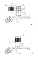
- the inventive system 1 comprises a valve 2, which with one end 3 with the coolant line 4 of a closed fluid circuit one here Not shown motor vehicle air conditioning is connected, and a protective cap 5, the on the free end 6, so on the not connected to the line 4 end 3 of the valve. 2 screwed or plugged, wherein in Fig. 1 for better illustration of the invention Systems 1, the protective cap 5 from the free end 6 of the valve 2 removed is.
- the free end 6 of the valve 2 is after removing the cap 5 with a here Filling and / or suction device not shown connected. To this end has the free end 6 of the valve 2 for locking the filling and / or suction device necessary and over a certain length appropriately trained outer profile 7 on.
- the outer profile 7 is formed by various waves and valleys.
- the length of the outer profile 7 having free end 6 of the valve 10 is illustrated by the in Fig. 1 alternatively inserted bracket 10.
- a sealing ring 9 is provided at the end 8, on the side facing the line 4 for locking the filling and / or suction necessary external profile 7 wherein the valve 2 for this purpose has a groove in its outer periphery, in which the sealing ring 9 is arranged.
Abstract
Description
- Fig. 1
- das erfindungsgemäße System aus Ventil und Schutzkappe, wobei die Schutzkappe vom Ventil abgenommen ist und
- Fig. 2
- das erfindungsgemäße System aus Ventil und Schutzkappe, wobei die Schutzkappe auf das Ventil aufgesteckt ist.
- 1
- System
- 2
- Ventil
- 3
- verbundenes Ende
- 4
- Leitung
- 5
- Schutzkappe
- 6
- freies Ende
- 7
- Außenprofil
- 8
- Ende des Außenprofils
- 9
- Dichtkörper
- 10
- Klammer
Claims (6)
- System (1) aus einem Ventil (2), das mit einem Ende (3) mit der Leitung (4) eines geschlossenen Fluidkreislaufs verbunden ist, und aus einer Schutzkappe (5), die auf das freie Ende (6), also auf das nicht mit der Leitung (4) verbundene Ende (3) des Ventils (2) aufgeschraubt oder aufgesteckt ist, wobei das freie Ende (6) des Ventils (2) nach Entfernen der Schutzkappe (5) mit einer Befüll- und/oder Absaugvorrichtung verbindbar ist und zu diesem Zweck ein zur Arretierung der Befüll- und/oder Absaugvorrichtung notwendiges und über eine bestimmte Länge entsprechend ausgebildetes Außenprofil (7) aufweist, dadurch gekennzeichnet, dass am Ende (8), auf der zur Leitung (4) weisenden Seite des zur Arretierung der Befüll- und/oder Absaugvorrichtung notwendigen Außenprofils (7) ein Dichtkörper (9) zwischen Ventil (2) und Schutzkappe (5) angeordnet ist.
- System (1) nach Anspruch 1, dadurch gekennzeichnet, dass das Ventil (2) in seinem Außenumfang eine Nut aufweist, in welcher der Dichtkörper (9) angeordnet ist.
- System (1) nach Anspruch 2, dadurch gekennzeichnet, dass die Nut eine Ringnut ist.
- System (1) nach einem der Ansprüche 1 bis 3, dadurch gekennzeichnet, dass der Dichtkörper (9) ein Dichtring, vorzugsweise ein O-Dichtring ist.
- System (1) nach einem der Ansprüche 1 bis 4, dadurch gekennzeichnet, dass das Ventil (2) aus einem Nichteisen-Metall, vorzugsweise Aluminium oder Messing, einem eisenhaltigen Metall, vorzugsweise Stahl oder Edelstahl, oder aus Kunststoff besteht.
- System (1) nach einem der Ansprüche 1 bis 5, dadurch gekennzeichnet, dass die Leitung (4) eine Kühlmittelleitung einer Klimaanlage, insbesondere einer Kraftfahrzeug-Klimaanlage, ist.
Applications Claiming Priority (2)
| Application Number | Priority Date | Filing Date | Title |
|---|---|---|---|
| DE102004027479A DE102004027479B3 (de) | 2004-06-04 | 2004-06-04 | System aus einem Ventil und einer Schutzkappe |
| DE102004027479 | 2004-06-04 |
Publications (3)
| Publication Number | Publication Date |
|---|---|
| EP1602872A2 true EP1602872A2 (de) | 2005-12-07 |
| EP1602872A3 EP1602872A3 (de) | 2006-04-12 |
| EP1602872B1 EP1602872B1 (de) | 2009-02-18 |
Family
ID=34833279
Family Applications (1)
| Application Number | Title | Priority Date | Filing Date |
|---|---|---|---|
| EP05103916A Active EP1602872B1 (de) | 2004-06-04 | 2005-05-11 | System aus Ventil und Schutzkappe |
Country Status (3)
| Country | Link |
|---|---|
| EP (1) | EP1602872B1 (de) |
| AT (1) | ATE423291T1 (de) |
| DE (2) | DE102004027479B3 (de) |
Cited By (2)
| Publication number | Priority date | Publication date | Assignee | Title |
|---|---|---|---|---|
| FR2927399A1 (fr) | 2008-02-13 | 2009-08-14 | Hutchinson Sa | Bouchon pour corps de valve de remplissage d'un circuit de climatisation pour vehicule automobile |
| FR3012200A1 (fr) * | 2013-10-22 | 2015-04-24 | Peugeot Citroen Automobiles Sa | Bouchon de valve de remplissage de fluide refrigerant et procede d'ejection sans outil d'un tel bouchon |
Families Citing this family (1)
| Publication number | Priority date | Publication date | Assignee | Title |
|---|---|---|---|---|
| DE102014219078A1 (de) | 2014-09-22 | 2016-03-24 | Mahle International Gmbh | Vorrichtung zur Zuführung eines Kühlmittels zu einem Wärmeübertrager, vorzugsweise für einen Abgaskühler eines Verbrennungsmotors eines Kraftfahrzeuges |
Citations (4)
| Publication number | Priority date | Publication date | Assignee | Title |
|---|---|---|---|---|
| GB1415840A (en) * | 1971-12-22 | 1975-11-26 | Busby Co Ltd | Resealable closures |
| DE3433206A1 (de) * | 1984-09-10 | 1985-05-02 | GOK Regler- und Armaturen GmbH & Co KG, 5200 Siegburg | Schutzkappe fuer schlauchsteckkupplungen |
| US5269342A (en) * | 1993-03-02 | 1993-12-14 | Midland Manufacturing Corp. | T-fitting |
| DE9411378U1 (de) * | 1994-07-14 | 1994-09-15 | Renk Tacke Gmbh | Hochdruck-Anschlußvorrichtung |
Family Cites Families (2)
| Publication number | Priority date | Publication date | Assignee | Title |
|---|---|---|---|---|
| DE4106314C2 (de) * | 1991-02-28 | 1999-12-02 | Teves Gmbh Alfred | Verschlußteil, insbesondere für einen Rohrstutzen an einer Wasserumwälzpumpe für ein Kraftfahrzeug |
| US5464114A (en) * | 1994-08-09 | 1995-11-07 | Green; Garrey D. | Cap for gas outlet nozzles |
-
2004
- 2004-06-04 DE DE102004027479A patent/DE102004027479B3/de not_active Expired - Fee Related
-
2005
- 2005-05-11 EP EP05103916A patent/EP1602872B1/de active Active
- 2005-05-11 AT AT05103916T patent/ATE423291T1/de not_active IP Right Cessation
- 2005-05-11 DE DE502005006632T patent/DE502005006632D1/de active Active
Patent Citations (4)
| Publication number | Priority date | Publication date | Assignee | Title |
|---|---|---|---|---|
| GB1415840A (en) * | 1971-12-22 | 1975-11-26 | Busby Co Ltd | Resealable closures |
| DE3433206A1 (de) * | 1984-09-10 | 1985-05-02 | GOK Regler- und Armaturen GmbH & Co KG, 5200 Siegburg | Schutzkappe fuer schlauchsteckkupplungen |
| US5269342A (en) * | 1993-03-02 | 1993-12-14 | Midland Manufacturing Corp. | T-fitting |
| DE9411378U1 (de) * | 1994-07-14 | 1994-09-15 | Renk Tacke Gmbh | Hochdruck-Anschlußvorrichtung |
Cited By (3)
| Publication number | Priority date | Publication date | Assignee | Title |
|---|---|---|---|---|
| FR2927399A1 (fr) | 2008-02-13 | 2009-08-14 | Hutchinson Sa | Bouchon pour corps de valve de remplissage d'un circuit de climatisation pour vehicule automobile |
| EP2090818A2 (de) | 2008-02-13 | 2009-08-19 | Hutchinson | Ventilkappe für Ventilkörper zum Auffüllen eines Klimaanlagenkreislaufs für Kraftfahrzeug |
| FR3012200A1 (fr) * | 2013-10-22 | 2015-04-24 | Peugeot Citroen Automobiles Sa | Bouchon de valve de remplissage de fluide refrigerant et procede d'ejection sans outil d'un tel bouchon |
Also Published As
| Publication number | Publication date |
|---|---|
| ATE423291T1 (de) | 2009-03-15 |
| EP1602872A3 (de) | 2006-04-12 |
| DE102004027479B3 (de) | 2005-09-08 |
| DE502005006632D1 (de) | 2009-04-02 |
| EP1602872B1 (de) | 2009-02-18 |
Similar Documents
| Publication | Publication Date | Title |
|---|---|---|
| DE4022558A1 (de) | Dichtungsvorrichtungen fuer durchflussoeffnungen | |
| EP2957809B1 (de) | Kupplungselement zur flexiblen verbindung zweier elemente zur führung von medien | |
| EP2008012B1 (de) | Steckverbinder für insbesondere aus kunststoff bestehende rohrleitungen | |
| DE19806742A1 (de) | Durchführungsarmatur | |
| EP1602872B1 (de) | System aus Ventil und Schutzkappe | |
| EP0327080A1 (de) | Rohrklemmverbindung | |
| EP1004805A2 (de) | Steckkupplung | |
| DE4005474A1 (de) | Anschlussarmatur fuer sicherheitsrohrleitungen aus thermoplastischen kunststoffen | |
| EP3408574B1 (de) | Kupplungskörper für eine steckverbindung von rohrleitungen, insbesondere kunststoffrohrleitungen | |
| DE102014114227A1 (de) | Verbindungsvorrichtung und Bauteilverbund | |
| EP1271038B1 (de) | Rohrverschraubung | |
| DE102009016081B4 (de) | Überstromventil | |
| DE102016209931A1 (de) | Anordnung zum Sammeln und Abführen von ausgetretenem Kältemittel | |
| DE102016103274A1 (de) | Rinne | |
| EP0786618A1 (de) | Anschlusselement für ein Zuleitungsrohr | |
| DE102017103433A1 (de) | Rohrverschraubung für metallische Rohrleitungen | |
| DE102017216157A1 (de) | Kraftstoffinjektoranordnung und ein Verfahren zum Einführen eines Kraftstoffinjektors in eine Aufnahmeöffnung eines Zylinderkopfs | |
| DE19842259B4 (de) | Abgangsvorrichtung für den dichten Anschluß einer Rohrleitung an einen Hauptsammler | |
| EP2023027A2 (de) | Schlauchanschluss | |
| DE102017107395A1 (de) | Rohrdichtung | |
| EP2042786B1 (de) | Dichtung und Dichtungsanordnung mit einer solchen Dichtung | |
| EP3168518A1 (de) | Anschlussvorrichtung für eine fluidführende leitung | |
| DE102017120936A1 (de) | Medienleitung | |
| DE102017118285A1 (de) | Vorrichtung zur optimierten Führung einer Hochdruckleitung durch eine Kupplungs-glocke eines Kupplungsbetätigungssystems | |
| DE102008026863B4 (de) | Kupplungseinrichtung zum Verbinden von Leitungseinrichtungen |
Legal Events
| Date | Code | Title | Description |
|---|---|---|---|
| PUAI | Public reference made under article 153(3) epc to a published international application that has entered the european phase |
Free format text: ORIGINAL CODE: 0009012 |
|
| AK | Designated contracting states |
Kind code of ref document: A2 Designated state(s): AT BE BG CH CY CZ DE DK EE ES FI FR GB GR HU IE IS IT LI LT LU MC NL PL PT RO SE SI SK TR |
|
| AX | Request for extension of the european patent |
Extension state: AL BA HR LV MK YU |
|
| PUAL | Search report despatched |
Free format text: ORIGINAL CODE: 0009013 |
|
| AK | Designated contracting states |
Kind code of ref document: A3 Designated state(s): AT BE BG CH CY CZ DE DK EE ES FI FR GB GR HU IE IS IT LI LT LU MC NL PL PT RO SE SI SK TR |
|
| AX | Request for extension of the european patent |
Extension state: AL BA HR LV MK YU |
|
| 17P | Request for examination filed |
Effective date: 20061012 |
|
| AKX | Designation fees paid |
Designated state(s): AT BE BG CH CY CZ DE DK EE ES FI FR GB GR HU IE IS IT LI LT LU MC NL PL PT RO SE SI SK TR |
|
| AXX | Extension fees paid |
Extension state: MK Payment date: 20061012 Extension state: BA Payment date: 20061012 Extension state: LV Payment date: 20061012 Extension state: HR Payment date: 20061012 Extension state: YU Payment date: 20061012 Extension state: AL Payment date: 20061012 |
|
| 17Q | First examination report despatched |
Effective date: 20070416 |
|
| GRAP | Despatch of communication of intention to grant a patent |
Free format text: ORIGINAL CODE: EPIDOSNIGR1 |
|
| GRAS | Grant fee paid |
Free format text: ORIGINAL CODE: EPIDOSNIGR3 |
|
| GRAA | (expected) grant |
Free format text: ORIGINAL CODE: 0009210 |
|
| AK | Designated contracting states |
Kind code of ref document: B1 Designated state(s): AT BE BG CH CY CZ DE DK EE ES FI FR GB GR HU IE IS IT LI LT LU MC NL PL PT RO SE SI SK TR |
|
| AX | Request for extension of the european patent |
Extension state: AL BA HR LV MK YU |
|
| REG | Reference to a national code |
Ref country code: GB Ref legal event code: FG4D Free format text: NOT ENGLISH |
|
| REG | Reference to a national code |
Ref country code: CH Ref legal event code: EP |
|
| REG | Reference to a national code |
Ref country code: IE Ref legal event code: FG4D Free format text: LANGUAGE OF EP DOCUMENT: GERMAN |
|
| REF | Corresponds to: |
Ref document number: 502005006632 Country of ref document: DE Date of ref document: 20090402 Kind code of ref document: P |
|
| PG25 | Lapsed in a contracting state [announced via postgrant information from national office to epo] |
Ref country code: FI Free format text: LAPSE BECAUSE OF FAILURE TO SUBMIT A TRANSLATION OF THE DESCRIPTION OR TO PAY THE FEE WITHIN THE PRESCRIBED TIME-LIMIT Effective date: 20090218 Ref country code: SI Free format text: LAPSE BECAUSE OF FAILURE TO SUBMIT A TRANSLATION OF THE DESCRIPTION OR TO PAY THE FEE WITHIN THE PRESCRIBED TIME-LIMIT Effective date: 20090218 Ref country code: LT Free format text: LAPSE BECAUSE OF FAILURE TO SUBMIT A TRANSLATION OF THE DESCRIPTION OR TO PAY THE FEE WITHIN THE PRESCRIBED TIME-LIMIT Effective date: 20090218 Ref country code: ES Free format text: LAPSE BECAUSE OF FAILURE TO SUBMIT A TRANSLATION OF THE DESCRIPTION OR TO PAY THE FEE WITHIN THE PRESCRIBED TIME-LIMIT Effective date: 20090529 Ref country code: NL Free format text: LAPSE BECAUSE OF FAILURE TO SUBMIT A TRANSLATION OF THE DESCRIPTION OR TO PAY THE FEE WITHIN THE PRESCRIBED TIME-LIMIT Effective date: 20090218 |
|
| NLV1 | Nl: lapsed or annulled due to failure to fulfill the requirements of art. 29p and 29m of the patents act | ||
| PG25 | Lapsed in a contracting state [announced via postgrant information from national office to epo] |
Ref country code: SE Free format text: LAPSE BECAUSE OF FAILURE TO SUBMIT A TRANSLATION OF THE DESCRIPTION OR TO PAY THE FEE WITHIN THE PRESCRIBED TIME-LIMIT Effective date: 20090518 Ref country code: PL Free format text: LAPSE BECAUSE OF FAILURE TO SUBMIT A TRANSLATION OF THE DESCRIPTION OR TO PAY THE FEE WITHIN THE PRESCRIBED TIME-LIMIT Effective date: 20090218 Ref country code: IS Free format text: LAPSE BECAUSE OF FAILURE TO SUBMIT A TRANSLATION OF THE DESCRIPTION OR TO PAY THE FEE WITHIN THE PRESCRIBED TIME-LIMIT Effective date: 20090618 |
|
| REG | Reference to a national code |
Ref country code: IE Ref legal event code: FD4D |
|
| PG25 | Lapsed in a contracting state [announced via postgrant information from national office to epo] |
Ref country code: IE Free format text: LAPSE BECAUSE OF FAILURE TO SUBMIT A TRANSLATION OF THE DESCRIPTION OR TO PAY THE FEE WITHIN THE PRESCRIBED TIME-LIMIT Effective date: 20090218 Ref country code: CZ Free format text: LAPSE BECAUSE OF FAILURE TO SUBMIT A TRANSLATION OF THE DESCRIPTION OR TO PAY THE FEE WITHIN THE PRESCRIBED TIME-LIMIT Effective date: 20090218 Ref country code: DK Free format text: LAPSE BECAUSE OF FAILURE TO SUBMIT A TRANSLATION OF THE DESCRIPTION OR TO PAY THE FEE WITHIN THE PRESCRIBED TIME-LIMIT Effective date: 20090218 Ref country code: PT Free format text: LAPSE BECAUSE OF FAILURE TO SUBMIT A TRANSLATION OF THE DESCRIPTION OR TO PAY THE FEE WITHIN THE PRESCRIBED TIME-LIMIT Effective date: 20090727 Ref country code: EE Free format text: LAPSE BECAUSE OF FAILURE TO SUBMIT A TRANSLATION OF THE DESCRIPTION OR TO PAY THE FEE WITHIN THE PRESCRIBED TIME-LIMIT Effective date: 20090218 |
|
| BERE | Be: lapsed |
Owner name: CONTITECH KUHNER G.M.B.H. & CIE. KG Effective date: 20090531 |
|
| PG25 | Lapsed in a contracting state [announced via postgrant information from national office to epo] |
Ref country code: RO Free format text: LAPSE BECAUSE OF FAILURE TO SUBMIT A TRANSLATION OF THE DESCRIPTION OR TO PAY THE FEE WITHIN THE PRESCRIBED TIME-LIMIT Effective date: 20090218 Ref country code: SK Free format text: LAPSE BECAUSE OF FAILURE TO SUBMIT A TRANSLATION OF THE DESCRIPTION OR TO PAY THE FEE WITHIN THE PRESCRIBED TIME-LIMIT Effective date: 20090218 |
|
| PLBE | No opposition filed within time limit |
Free format text: ORIGINAL CODE: 0009261 |
|
| STAA | Information on the status of an ep patent application or granted ep patent |
Free format text: STATUS: NO OPPOSITION FILED WITHIN TIME LIMIT |
|
| PG25 | Lapsed in a contracting state [announced via postgrant information from national office to epo] |
Ref country code: MC Free format text: LAPSE BECAUSE OF NON-PAYMENT OF DUE FEES Effective date: 20090531 |
|
| REG | Reference to a national code |
Ref country code: CH Ref legal event code: PL |
|
| 26N | No opposition filed |
Effective date: 20091119 |
|
| GBPC | Gb: european patent ceased through non-payment of renewal fee |
Effective date: 20090518 |
|
| PG25 | Lapsed in a contracting state [announced via postgrant information from national office to epo] |
Ref country code: LI Free format text: LAPSE BECAUSE OF NON-PAYMENT OF DUE FEES Effective date: 20090531 Ref country code: CH Free format text: LAPSE BECAUSE OF NON-PAYMENT OF DUE FEES Effective date: 20090531 Ref country code: BG Free format text: LAPSE BECAUSE OF FAILURE TO SUBMIT A TRANSLATION OF THE DESCRIPTION OR TO PAY THE FEE WITHIN THE PRESCRIBED TIME-LIMIT Effective date: 20090518 |
|
| REG | Reference to a national code |
Ref country code: FR Ref legal event code: ST Effective date: 20100129 |
|
| PG25 | Lapsed in a contracting state [announced via postgrant information from national office to epo] |
Ref country code: FR Free format text: LAPSE BECAUSE OF NON-PAYMENT OF DUE FEES Effective date: 20090602 |
|
| PG25 | Lapsed in a contracting state [announced via postgrant information from national office to epo] |
Ref country code: GB Free format text: LAPSE BECAUSE OF NON-PAYMENT OF DUE FEES Effective date: 20090518 |
|
| PG25 | Lapsed in a contracting state [announced via postgrant information from national office to epo] |
Ref country code: BE Free format text: LAPSE BECAUSE OF NON-PAYMENT OF DUE FEES Effective date: 20090531 |
|
| PG25 | Lapsed in a contracting state [announced via postgrant information from national office to epo] |
Ref country code: AT Free format text: LAPSE BECAUSE OF NON-PAYMENT OF DUE FEES Effective date: 20090511 |
|
| PG25 | Lapsed in a contracting state [announced via postgrant information from national office to epo] |
Ref country code: GR Free format text: LAPSE BECAUSE OF FAILURE TO SUBMIT A TRANSLATION OF THE DESCRIPTION OR TO PAY THE FEE WITHIN THE PRESCRIBED TIME-LIMIT Effective date: 20090519 |
|
| PG25 | Lapsed in a contracting state [announced via postgrant information from national office to epo] |
Ref country code: IT Free format text: LAPSE BECAUSE OF FAILURE TO SUBMIT A TRANSLATION OF THE DESCRIPTION OR TO PAY THE FEE WITHIN THE PRESCRIBED TIME-LIMIT Effective date: 20090218 |
|
| PG25 | Lapsed in a contracting state [announced via postgrant information from national office to epo] |
Ref country code: LU Free format text: LAPSE BECAUSE OF NON-PAYMENT OF DUE FEES Effective date: 20090511 |
|
| PG25 | Lapsed in a contracting state [announced via postgrant information from national office to epo] |
Ref country code: HU Free format text: LAPSE BECAUSE OF FAILURE TO SUBMIT A TRANSLATION OF THE DESCRIPTION OR TO PAY THE FEE WITHIN THE PRESCRIBED TIME-LIMIT Effective date: 20090819 |
|
| PG25 | Lapsed in a contracting state [announced via postgrant information from national office to epo] |
Ref country code: TR Free format text: LAPSE BECAUSE OF FAILURE TO SUBMIT A TRANSLATION OF THE DESCRIPTION OR TO PAY THE FEE WITHIN THE PRESCRIBED TIME-LIMIT Effective date: 20090218 |
|
| PG25 | Lapsed in a contracting state [announced via postgrant information from national office to epo] |
Ref country code: CY Free format text: LAPSE BECAUSE OF FAILURE TO SUBMIT A TRANSLATION OF THE DESCRIPTION OR TO PAY THE FEE WITHIN THE PRESCRIBED TIME-LIMIT Effective date: 20090218 |
|
| REG | Reference to a national code |
Ref country code: DE Ref legal event code: R081 Ref document number: 502005006632 Country of ref document: DE Owner name: CONTITECH TECHNO-CHEMIE GMBH, DE Free format text: FORMER OWNER: CONTITECH KUEHNER GMBH & CIE. KG, 71570 OPPENWEILER, DE |
|
| PGFP | Annual fee paid to national office [announced via postgrant information from national office to epo] |
Ref country code: DE Payment date: 20220531 Year of fee payment: 18 |
|
| REG | Reference to a national code |
Ref country code: DE Ref legal event code: R119 Ref document number: 502005006632 Country of ref document: DE |