EP3491986B1 - Appareil de nettoyage de surface - Google Patents
Appareil de nettoyage de surface Download PDFInfo
- Publication number
- EP3491986B1 EP3491986B1 EP18211523.8A EP18211523A EP3491986B1 EP 3491986 B1 EP3491986 B1 EP 3491986B1 EP 18211523 A EP18211523 A EP 18211523A EP 3491986 B1 EP3491986 B1 EP 3491986B1
- Authority
- EP
- European Patent Office
- Prior art keywords
- fluid
- assembly
- cleaning apparatus
- brushroll
- surface cleaning
- Prior art date
- Legal status (The legal status is an assumption and is not a legal conclusion. Google has not performed a legal analysis and makes no representation as to the accuracy of the status listed.)
- Revoked
Links
- 238000004140 cleaning Methods 0.000 title claims description 107
- 239000012530 fluid Substances 0.000 claims description 231
- 239000007921 spray Substances 0.000 claims description 37
- 230000037361 pathway Effects 0.000 claims description 36
- 238000004891 communication Methods 0.000 claims description 20
- 239000000463 material Substances 0.000 claims description 20
- 239000007788 liquid Substances 0.000 claims description 14
- 230000033001 locomotion Effects 0.000 claims description 12
- 229920001410 Microfiber Polymers 0.000 claims description 8
- 239000003658 microfiber Substances 0.000 claims description 8
- -1 polypropylene Polymers 0.000 claims description 6
- 230000009977 dual effect Effects 0.000 claims description 5
- 238000007667 floating Methods 0.000 claims description 5
- 229920000728 polyester Polymers 0.000 claims description 5
- 239000012780 transparent material Substances 0.000 claims description 5
- 238000010407 vacuum cleaning Methods 0.000 claims description 4
- 239000004743 Polypropylene Substances 0.000 claims description 3
- 229920001155 polypropylene Polymers 0.000 claims description 3
- 239000004952 Polyamide Substances 0.000 claims description 2
- 238000013019 agitation Methods 0.000 claims description 2
- 239000000835 fiber Substances 0.000 claims description 2
- 239000002184 metal Substances 0.000 claims description 2
- 229920002647 polyamide Polymers 0.000 claims description 2
- 239000002023 wood Substances 0.000 claims 1
- 238000011084 recovery Methods 0.000 description 50
- 238000003860 storage Methods 0.000 description 21
- 230000007246 mechanism Effects 0.000 description 9
- 238000010586 diagram Methods 0.000 description 6
- XLYOFNOQVPJJNP-UHFFFAOYSA-N water Substances O XLYOFNOQVPJJNP-UHFFFAOYSA-N 0.000 description 5
- PPBRXRYQALVLMV-UHFFFAOYSA-N Styrene Chemical compound C=CC1=CC=CC=C1 PPBRXRYQALVLMV-UHFFFAOYSA-N 0.000 description 4
- 238000001035 drying Methods 0.000 description 4
- 230000005540 biological transmission Effects 0.000 description 3
- 230000008878 coupling Effects 0.000 description 3
- 238000010168 coupling process Methods 0.000 description 3
- 238000005859 coupling reaction Methods 0.000 description 3
- 239000003599 detergent Substances 0.000 description 3
- 229920001971 elastomer Polymers 0.000 description 3
- 230000014759 maintenance of location Effects 0.000 description 3
- 239000000203 mixture Substances 0.000 description 3
- 239000005060 rubber Substances 0.000 description 3
- 239000007787 solid Substances 0.000 description 3
- 238000011144 upstream manufacturing Methods 0.000 description 3
- 239000004677 Nylon Substances 0.000 description 2
- 238000010521 absorption reaction Methods 0.000 description 2
- 230000003213 activating effect Effects 0.000 description 2
- 230000000994 depressogenic effect Effects 0.000 description 2
- 239000000428 dust Substances 0.000 description 2
- 239000011121 hardwood Substances 0.000 description 2
- 238000005286 illumination Methods 0.000 description 2
- 230000013011 mating Effects 0.000 description 2
- 238000000034 method Methods 0.000 description 2
- 229920001778 nylon Polymers 0.000 description 2
- 238000003825 pressing Methods 0.000 description 2
- 239000000243 solution Substances 0.000 description 2
- 238000005200 wet scrubbing Methods 0.000 description 2
- ARXHIJMGSIYYRZ-UHFFFAOYSA-N 1,2,4-trichloro-3-(3,4-dichlorophenyl)benzene Chemical compound C1=C(Cl)C(Cl)=CC=C1C1=C(Cl)C=CC(Cl)=C1Cl ARXHIJMGSIYYRZ-UHFFFAOYSA-N 0.000 description 1
- NLHHRLWOUZZQLW-UHFFFAOYSA-N Acrylonitrile Chemical compound C=CC#N NLHHRLWOUZZQLW-UHFFFAOYSA-N 0.000 description 1
- 229920000459 Nitrile rubber Polymers 0.000 description 1
- 230000004913 activation Effects 0.000 description 1
- 239000012459 cleaning agent Substances 0.000 description 1
- 230000021615 conjugation Effects 0.000 description 1
- 238000001816 cooling Methods 0.000 description 1
- 230000007423 decrease Effects 0.000 description 1
- 238000005553 drilling Methods 0.000 description 1
- 238000009429 electrical wiring Methods 0.000 description 1
- 239000000284 extract Substances 0.000 description 1
- 230000005484 gravity Effects 0.000 description 1
- 238000010438 heat treatment Methods 0.000 description 1
- 238000001746 injection moulding Methods 0.000 description 1
- 230000003993 interaction Effects 0.000 description 1
- 238000012423 maintenance Methods 0.000 description 1
- 238000004519 manufacturing process Methods 0.000 description 1
- 230000004048 modification Effects 0.000 description 1
- 238000012986 modification Methods 0.000 description 1
- 238000000465 moulding Methods 0.000 description 1
- 239000004033 plastic Substances 0.000 description 1
- 229920000915 polyvinyl chloride Polymers 0.000 description 1
- 239000004800 polyvinyl chloride Substances 0.000 description 1
- 230000002265 prevention Effects 0.000 description 1
- 239000002689 soil Substances 0.000 description 1
- 230000003068 static effect Effects 0.000 description 1
- 210000003813 thumb Anatomy 0.000 description 1
Images


Classifications
-
- A—HUMAN NECESSITIES
- A47—FURNITURE; DOMESTIC ARTICLES OR APPLIANCES; COFFEE MILLS; SPICE MILLS; SUCTION CLEANERS IN GENERAL
- A47L—DOMESTIC WASHING OR CLEANING; SUCTION CLEANERS IN GENERAL
- A47L11/00—Machines for cleaning floors, carpets, furniture, walls, or wall coverings
- A47L11/02—Floor surfacing or polishing machines
- A47L11/20—Floor surfacing or polishing machines combined with vacuum cleaning devices
- A47L11/201—Floor surfacing or polishing machines combined with vacuum cleaning devices with supply of cleaning agents
-
- A—HUMAN NECESSITIES
- A47—FURNITURE; DOMESTIC ARTICLES OR APPLIANCES; COFFEE MILLS; SPICE MILLS; SUCTION CLEANERS IN GENERAL
- A47L—DOMESTIC WASHING OR CLEANING; SUCTION CLEANERS IN GENERAL
- A47L9/00—Details or accessories of suction cleaners, e.g. mechanical means for controlling the suction or for effecting pulsating action; Storing devices specially adapted to suction cleaners or parts thereof; Carrying-vehicles specially adapted for suction cleaners
- A47L9/02—Nozzles
- A47L9/04—Nozzles with driven brushes or agitators
- A47L9/0461—Dust-loosening tools, e.g. agitators, brushes
- A47L9/0466—Rotating tools
- A47L9/0477—Rolls
-
- A—HUMAN NECESSITIES
- A46—BRUSHWARE
- A46B—BRUSHES
- A46B1/00—Brush bodies and bristles moulded as a unit
-
- A—HUMAN NECESSITIES
- A46—BRUSHWARE
- A46B—BRUSHES
- A46B13/00—Brushes with driven brush bodies or carriers
- A46B13/001—Cylindrical or annular brush bodies
-
- A—HUMAN NECESSITIES
- A46—BRUSHWARE
- A46B—BRUSHES
- A46B15/00—Other brushes; Brushes with additional arrangements
- A46B15/0002—Arrangements for enhancing monitoring or controlling the brushing process
- A46B15/0053—Brushes fitted with ventilation suction, e.g. for removing dust
-
- A—HUMAN NECESSITIES
- A46—BRUSHWARE
- A46B—BRUSHES
- A46B9/00—Arrangements of the bristles in the brush body
- A46B9/06—Arrangement of mixed bristles or tufts of bristles, e.g. wire, fibre, rubber
-
- A—HUMAN NECESSITIES
- A46—BRUSHWARE
- A46D—MANUFACTURE OF BRUSHES
- A46D1/00—Bristles; Selection of materials for bristles
- A46D1/02—Bristles details
- A46D1/0207—Bristles characterised by the choice of material, e.g. metal
-
- A—HUMAN NECESSITIES
- A47—FURNITURE; DOMESTIC ARTICLES OR APPLIANCES; COFFEE MILLS; SPICE MILLS; SUCTION CLEANERS IN GENERAL
- A47L—DOMESTIC WASHING OR CLEANING; SUCTION CLEANERS IN GENERAL
- A47L11/00—Machines for cleaning floors, carpets, furniture, walls, or wall coverings
- A47L11/02—Floor surfacing or polishing machines
- A47L11/04—Floor surfacing or polishing machines hand-driven
- A47L11/08—Floor surfacing or polishing machines hand-driven with rotating tools
- A47L11/085—Floor surfacing or polishing machines hand-driven with rotating tools with supply of cleaning agents
-
- A—HUMAN NECESSITIES
- A47—FURNITURE; DOMESTIC ARTICLES OR APPLIANCES; COFFEE MILLS; SPICE MILLS; SUCTION CLEANERS IN GENERAL
- A47L—DOMESTIC WASHING OR CLEANING; SUCTION CLEANERS IN GENERAL
- A47L11/00—Machines for cleaning floors, carpets, furniture, walls, or wall coverings
- A47L11/02—Floor surfacing or polishing machines
- A47L11/10—Floor surfacing or polishing machines motor-driven
- A47L11/14—Floor surfacing or polishing machines motor-driven with rotating tools
- A47L11/18—Floor surfacing or polishing machines motor-driven with rotating tools the tools being roll brushes
-
- A—HUMAN NECESSITIES
- A47—FURNITURE; DOMESTIC ARTICLES OR APPLIANCES; COFFEE MILLS; SPICE MILLS; SUCTION CLEANERS IN GENERAL
- A47L—DOMESTIC WASHING OR CLEANING; SUCTION CLEANERS IN GENERAL
- A47L11/00—Machines for cleaning floors, carpets, furniture, walls, or wall coverings
- A47L11/02—Floor surfacing or polishing machines
- A47L11/20—Floor surfacing or polishing machines combined with vacuum cleaning devices
- A47L11/202—Floor surfacing or polishing machines combined with vacuum cleaning devices having separate drive for the cleaning brushes
-
- A—HUMAN NECESSITIES
- A47—FURNITURE; DOMESTIC ARTICLES OR APPLIANCES; COFFEE MILLS; SPICE MILLS; SUCTION CLEANERS IN GENERAL
- A47L—DOMESTIC WASHING OR CLEANING; SUCTION CLEANERS IN GENERAL
- A47L11/00—Machines for cleaning floors, carpets, furniture, walls, or wall coverings
- A47L11/02—Floor surfacing or polishing machines
- A47L11/20—Floor surfacing or polishing machines combined with vacuum cleaning devices
- A47L11/204—Floor surfacing or polishing machines combined with vacuum cleaning devices having combined drive for brushes and for vacuum cleaning
- A47L11/206—Floor surfacing or polishing machines combined with vacuum cleaning devices having combined drive for brushes and for vacuum cleaning for rotary disc brushes
-
- A—HUMAN NECESSITIES
- A47—FURNITURE; DOMESTIC ARTICLES OR APPLIANCES; COFFEE MILLS; SPICE MILLS; SUCTION CLEANERS IN GENERAL
- A47L—DOMESTIC WASHING OR CLEANING; SUCTION CLEANERS IN GENERAL
- A47L11/00—Machines for cleaning floors, carpets, furniture, walls, or wall coverings
- A47L11/29—Floor-scrubbing machines characterised by means for taking-up dirty liquid
- A47L11/30—Floor-scrubbing machines characterised by means for taking-up dirty liquid by suction
- A47L11/302—Floor-scrubbing machines characterised by means for taking-up dirty liquid by suction having rotary tools
-
- A—HUMAN NECESSITIES
- A47—FURNITURE; DOMESTIC ARTICLES OR APPLIANCES; COFFEE MILLS; SPICE MILLS; SUCTION CLEANERS IN GENERAL
- A47L—DOMESTIC WASHING OR CLEANING; SUCTION CLEANERS IN GENERAL
- A47L11/00—Machines for cleaning floors, carpets, furniture, walls, or wall coverings
- A47L11/40—Parts or details of machines not provided for in groups A47L11/02 - A47L11/38, or not restricted to one of these groups, e.g. handles, arrangements of switches, skirts, buffers, levers
- A47L11/4002—Installations of electric equipment
- A47L11/4008—Arrangements of switches, indicators or the like
-
- A—HUMAN NECESSITIES
- A47—FURNITURE; DOMESTIC ARTICLES OR APPLIANCES; COFFEE MILLS; SPICE MILLS; SUCTION CLEANERS IN GENERAL
- A47L—DOMESTIC WASHING OR CLEANING; SUCTION CLEANERS IN GENERAL
- A47L11/00—Machines for cleaning floors, carpets, furniture, walls, or wall coverings
- A47L11/40—Parts or details of machines not provided for in groups A47L11/02 - A47L11/38, or not restricted to one of these groups, e.g. handles, arrangements of switches, skirts, buffers, levers
- A47L11/4013—Contaminants collecting devices, i.e. hoppers, tanks or the like
- A47L11/4016—Contaminants collecting devices, i.e. hoppers, tanks or the like specially adapted for collecting fluids
-
- A—HUMAN NECESSITIES
- A47—FURNITURE; DOMESTIC ARTICLES OR APPLIANCES; COFFEE MILLS; SPICE MILLS; SUCTION CLEANERS IN GENERAL
- A47L—DOMESTIC WASHING OR CLEANING; SUCTION CLEANERS IN GENERAL
- A47L11/00—Machines for cleaning floors, carpets, furniture, walls, or wall coverings
- A47L11/40—Parts or details of machines not provided for in groups A47L11/02 - A47L11/38, or not restricted to one of these groups, e.g. handles, arrangements of switches, skirts, buffers, levers
- A47L11/4036—Parts or details of the surface treating tools
- A47L11/4041—Roll shaped surface treating tools
-
- A—HUMAN NECESSITIES
- A47—FURNITURE; DOMESTIC ARTICLES OR APPLIANCES; COFFEE MILLS; SPICE MILLS; SUCTION CLEANERS IN GENERAL
- A47L—DOMESTIC WASHING OR CLEANING; SUCTION CLEANERS IN GENERAL
- A47L11/00—Machines for cleaning floors, carpets, furniture, walls, or wall coverings
- A47L11/40—Parts or details of machines not provided for in groups A47L11/02 - A47L11/38, or not restricted to one of these groups, e.g. handles, arrangements of switches, skirts, buffers, levers
- A47L11/4036—Parts or details of the surface treating tools
- A47L11/4044—Vacuuming or pick-up tools; Squeegees
-
- A—HUMAN NECESSITIES
- A47—FURNITURE; DOMESTIC ARTICLES OR APPLIANCES; COFFEE MILLS; SPICE MILLS; SUCTION CLEANERS IN GENERAL
- A47L—DOMESTIC WASHING OR CLEANING; SUCTION CLEANERS IN GENERAL
- A47L11/00—Machines for cleaning floors, carpets, furniture, walls, or wall coverings
- A47L11/40—Parts or details of machines not provided for in groups A47L11/02 - A47L11/38, or not restricted to one of these groups, e.g. handles, arrangements of switches, skirts, buffers, levers
- A47L11/408—Means for supplying cleaning or surface treating agents
- A47L11/4083—Liquid supply reservoirs; Preparation of the agents, e.g. mixing devices
-
- A—HUMAN NECESSITIES
- A47—FURNITURE; DOMESTIC ARTICLES OR APPLIANCES; COFFEE MILLS; SPICE MILLS; SUCTION CLEANERS IN GENERAL
- A47L—DOMESTIC WASHING OR CLEANING; SUCTION CLEANERS IN GENERAL
- A47L11/00—Machines for cleaning floors, carpets, furniture, walls, or wall coverings
- A47L11/40—Parts or details of machines not provided for in groups A47L11/02 - A47L11/38, or not restricted to one of these groups, e.g. handles, arrangements of switches, skirts, buffers, levers
- A47L11/408—Means for supplying cleaning or surface treating agents
- A47L11/4086—Arrangements for steam generation
-
- A—HUMAN NECESSITIES
- A47—FURNITURE; DOMESTIC ARTICLES OR APPLIANCES; COFFEE MILLS; SPICE MILLS; SUCTION CLEANERS IN GENERAL
- A47L—DOMESTIC WASHING OR CLEANING; SUCTION CLEANERS IN GENERAL
- A47L11/00—Machines for cleaning floors, carpets, furniture, walls, or wall coverings
- A47L11/40—Parts or details of machines not provided for in groups A47L11/02 - A47L11/38, or not restricted to one of these groups, e.g. handles, arrangements of switches, skirts, buffers, levers
- A47L11/408—Means for supplying cleaning or surface treating agents
- A47L11/4088—Supply pumps; Spraying devices; Supply conduits
-
- A—HUMAN NECESSITIES
- A47—FURNITURE; DOMESTIC ARTICLES OR APPLIANCES; COFFEE MILLS; SPICE MILLS; SUCTION CLEANERS IN GENERAL
- A47L—DOMESTIC WASHING OR CLEANING; SUCTION CLEANERS IN GENERAL
- A47L5/00—Structural features of suction cleaners
- A47L5/12—Structural features of suction cleaners with power-driven air-pumps or air-compressors, e.g. driven by motor vehicle engine vacuum
- A47L5/22—Structural features of suction cleaners with power-driven air-pumps or air-compressors, e.g. driven by motor vehicle engine vacuum with rotary fans
- A47L5/24—Hand-supported suction cleaners
- A47L5/26—Hand-supported suction cleaners with driven dust-loosening tools
-
- A—HUMAN NECESSITIES
- A47—FURNITURE; DOMESTIC ARTICLES OR APPLIANCES; COFFEE MILLS; SPICE MILLS; SUCTION CLEANERS IN GENERAL
- A47L—DOMESTIC WASHING OR CLEANING; SUCTION CLEANERS IN GENERAL
- A47L5/00—Structural features of suction cleaners
- A47L5/12—Structural features of suction cleaners with power-driven air-pumps or air-compressors, e.g. driven by motor vehicle engine vacuum
- A47L5/22—Structural features of suction cleaners with power-driven air-pumps or air-compressors, e.g. driven by motor vehicle engine vacuum with rotary fans
- A47L5/28—Suction cleaners with handles and nozzles fixed on the casings, e.g. wheeled suction cleaners with steering handle
- A47L5/30—Suction cleaners with handles and nozzles fixed on the casings, e.g. wheeled suction cleaners with steering handle with driven dust-loosening tools, e.g. rotating brushes
-
- A—HUMAN NECESSITIES
- A47—FURNITURE; DOMESTIC ARTICLES OR APPLIANCES; COFFEE MILLS; SPICE MILLS; SUCTION CLEANERS IN GENERAL
- A47L—DOMESTIC WASHING OR CLEANING; SUCTION CLEANERS IN GENERAL
- A47L7/00—Suction cleaners adapted for additional purposes; Tables with suction openings for cleaning purposes; Containers for cleaning articles by suction; Suction cleaners adapted to cleaning of brushes; Suction cleaners adapted to taking-up liquids
- A47L7/0004—Suction cleaners adapted to take up liquids, e.g. wet or dry vacuum cleaners
- A47L7/0014—Suction cleaners adapted to take up liquids, e.g. wet or dry vacuum cleaners with additional means or devices between nozzle and casing
-
- A—HUMAN NECESSITIES
- A47—FURNITURE; DOMESTIC ARTICLES OR APPLIANCES; COFFEE MILLS; SPICE MILLS; SUCTION CLEANERS IN GENERAL
- A47L—DOMESTIC WASHING OR CLEANING; SUCTION CLEANERS IN GENERAL
- A47L9/00—Details or accessories of suction cleaners, e.g. mechanical means for controlling the suction or for effecting pulsating action; Storing devices specially adapted to suction cleaners or parts thereof; Carrying-vehicles specially adapted for suction cleaners
- A47L9/02—Nozzles
- A47L9/04—Nozzles with driven brushes or agitators
- A47L9/0461—Dust-loosening tools, e.g. agitators, brushes
-
- A—HUMAN NECESSITIES
- A47—FURNITURE; DOMESTIC ARTICLES OR APPLIANCES; COFFEE MILLS; SPICE MILLS; SUCTION CLEANERS IN GENERAL
- A47L—DOMESTIC WASHING OR CLEANING; SUCTION CLEANERS IN GENERAL
- A47L9/00—Details or accessories of suction cleaners, e.g. mechanical means for controlling the suction or for effecting pulsating action; Storing devices specially adapted to suction cleaners or parts thereof; Carrying-vehicles specially adapted for suction cleaners
- A47L9/28—Installation of the electric equipment, e.g. adaptation or attachment to the suction cleaner; Controlling suction cleaners by electric means
- A47L9/30—Arrangement of illuminating devices
-
- A—HUMAN NECESSITIES
- A47—FURNITURE; DOMESTIC ARTICLES OR APPLIANCES; COFFEE MILLS; SPICE MILLS; SUCTION CLEANERS IN GENERAL
- A47L—DOMESTIC WASHING OR CLEANING; SUCTION CLEANERS IN GENERAL
- A47L9/00—Details or accessories of suction cleaners, e.g. mechanical means for controlling the suction or for effecting pulsating action; Storing devices specially adapted to suction cleaners or parts thereof; Carrying-vehicles specially adapted for suction cleaners
- A47L9/32—Handles
- A47L9/322—Handles for hand-supported suction cleaners
Definitions
- Multi-surface vacuum cleaners are adapted for cleaning hard floor surfaces such as tile and hardwood and soft floor surfaces such as carpet and upholstery. Some examples can be seen in US2002/026683 , WO2014/095614 and GB2458220 .
- Some multi-surface vacuum cleaners comprise a fluid delivery system that delivers cleaning fluid to a surface to be cleaned and a fluid recovery system that extracts spent cleaning fluid and debris (which may include dirt, dust, stains, soil, hair, and other debris) from the surface.
- the fluid delivery system typically includes one or more fluid supply tanks for storing a supply of cleaning fluid, a fluid distributor for applying the cleaning fluid to the surface to be cleaned, and a fluid supply conduit for delivering the cleaning fluid from the fluid supply tank to the fluid distributor.
- An agitator can be provided for agitating the cleaning fluid on the surface.
- the fluid recovery system typically includes a recovery tank, a nozzle adjacent the surface to be cleaned and in fluid communication with the recovery tank through a working air conduit, and a source of suction in fluid communication with the working air conduit to draw the cleaning fluid from the surface to be cleaned and through the nozzle and the working air conduit to the recovery tank.
- Other multi-surface cleaning apparatuses include "dry" vacuum cleaners which can clean different surface types, but do not dispense or recover liquid.
- a surface cleaning apparatus includes a housing including an upright handle assembly and a base mounted to the handle assembly and adapted for movement across a surface to be cleaned, a suction source, a suction nozzle assembly provided on the base and defining a suction nozzle in fluid communication with the suction source, the suction nozzle assembly comprising a nozzle housing and a cover on the nozzle housing, and a fluid delivery system provided on the housing.
- the fluid delivery system includes a fluid supply chamber adapted to hold a supply of liquid, a fluid dispenser provided on the base in fluid communication with the fluid supply chamber, a fluid delivery pathway between the fluid supply chamber and the fluid dispenser, and at least one fluid delivery channel forming a portion of the fluid delivery pathway, the at least one fluid delivery channel being formed between the nozzle housing and the cover.
- a surface cleaning apparatus includes a housing including an upright handle assembly and a base mounted to the handle assembly and adapted for movement across a surface to be cleaned, a fluid recovery system comprising a suction source and a dirty air inlet provided on the base in fluid communication with the suction source, a fluid delivery system provided on the housing and comprising a fluid supply chamber adapted to hold a supply of liquid, a fluid dispenser provided on the base in fluid communication with the fluid supply chamber, and a fluid delivery pathway between the fluid supply chamber and the fluid dispenser comprising at least one fluid delivery channel provided on the base, an actuator provided on the housing and operably coupled with the fluid delivery system to delivery fluid to the fluid dispenser via the fluid delivery pathway, and a light operably coupled with the actuator and provided on the base adjacent the at least one fluid delivery channel and adapted to illuminate the fluid delivery channel upon actuation of the actuator.
- the invention generally relates to a surface cleaning apparatus, which may be in the form of a multi-surface wet vacuum cleaner.
- a surface cleaning apparatus is provided with a dual wiper configuration in the nozzle having multiple functions to reduce streaking of fluid on surface to be cleaned and improve dry debris removal.
- One wiper aids in distributing cleaning fluid evenly along the length of the agitator and eliminating excess fluid on the agitator, while a second wiper scrapes the surface to be cleaned while introducing fluid and debris into the suction nozzle to prevent streaking on the surface as well as to prevent dry debris scatter while agitator is activated.
- a surface cleaning apparatus is provided with a hybrid brushroll that includes multiple agitation materials to optimize cleaning performance on different types of surfaces to be cleaned, including hard and soft surfaces, and for different cleaning modes, including wet and dry vacuum cleaning.
- a surface cleaning apparatus is provided with integrated fluid delivery channels that reduce the number of additional components such as tubing, fittings, and clamps, which decreases the cost of manufacture and increases ease of maintenance for the user.
- a surface cleaning apparatus is provided with a fluid dispenser configured to wet a brushroll evenly and uniformly across the entire length of the brushroll.
- a surface cleaning apparatus is provided with a visible indicator system operably connected to cleaning fluid actuation which allows the cleaning fluid delivery flow improved visibility and feedback to the user regarding fluid delivery function.
- a surface cleaning apparatus is provided with a storage tray that can be used during a self-cleaning mode of the surface cleaning apparatus and for drying a brushroll of the apparatus.
- the functional systems of the surface cleaning apparatus can be arranged into any desired configuration, such as an upright device having a base and an upright body for directing the base across the surface to be cleaned, a canister device having a cleaning implement connected to a wheeled base by a vacuum hose, a portable device adapted to be hand carried by a user for cleaning relatively small areas, or a commercial device.
- Any of the aforementioned cleaners can be adapted to include a flexible vacuum hose, which can form a portion of the working air conduit between a nozzle and the suction source.
- the term "multi-surface wet vacuum cleaner” includes a vacuum cleaner that can be used to clean hard floor surfaces such as tile and hardwood and soft floor surfaces such as carpet.
- the cleaner can include a fluid delivery system for storing cleaning fluid and delivering the cleaning fluid to the surface to be cleaned and a recovery system for removing the spent cleaning fluid and debris from the surface to be cleaned and storing the spent cleaning fluid and debris.
- the recovery system can include a suction nozzle, a suction source in fluid communication with the suction nozzle for generating a working air stream, and a recovery container for separating and collecting fluid and debris from the working airstream for later disposal.
- a separator can be formed in a portion of the recovery container for separating fluid and entrained debris from the working airstream.
- the recovery system can also be provided with one or more additional filters upstream or downstream of the motor/fan assembly.
- the suction source such as a motor/fan assembly, is provided in fluid communication with the recovery container and can be electrically coupled to a power source.
- the suction nozzle can be provided on a base or cleaning head adapted to move over the surface to be cleaned.
- An agitator can be provided adjacent to the suction nozzle for agitating the surface to be cleaned so that the debris is more easily ingested into the suction nozzle.
- the agitator can be driven by the same motor/fan assembly serving as the suction source, or may optionally be driven by a separate drive assembly, such as a dedicated agitator motor as shown herein.
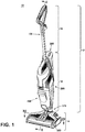
- FIG. 1 is a perspective view illustrating one non-limiting example of a surface cleaning apparatus in the form of multi-surface wet vacuum cleaner 10, according to one embodiment of the invention.
- the multi-surface wet vacuum cleaner 10 is an upright multi-surface wet vacuum cleaner having a housing that includes an upright body or handle assembly 12 and a base 14 pivotally and/or swivel mounted to the upright handle assembly 12 and adapted for movement across a surface to be cleaned.
- the terms "upper,” “lower,” “right,” “left,” “rear,” “front,” “vertical,” “horizontal,” “inner,” “outer,” and derivatives thereof shall relate to the invention as oriented in FIG. 1 from the perspective of a user behind the multi-surface wet vacuum cleaner 10, which defines the rear of the multi-surface wet vacuum cleaner 10.
- the invention may assume various alternative orientations, except where expressly specified to the contrary.
- the upright handle assembly 12 comprises an upper handle 16 and a frame 18.
- Upper handle 16 comprises a handle assembly 100.
- Frame 18 comprises a main support section or body assembly 200 supporting at least a clean tank assembly 300 and a dirty tank assembly 400, and may further support additional components of the handle assembly 12.
- the base 14 comprises a foot assembly 500.
- the multi-surface wet vacuum cleaner 10 can include a fluid delivery or supply pathway, including and at least partially defined by the clean tank assembly 300, for storing cleaning fluid and delivering the cleaning fluid to the surface to be cleaned and a fluid recovery pathway, including and at least partially defined by the dirty tank assembly 400, for removing the spent cleaning fluid and debris from the surface to be cleaned and storing the spent cleaning fluid and debris until emptied by the user.
- a pivotable swivel joint assembly 570 is formed at a lower end of the frame 18 and moveably mounts the base 14 to the upright assembly 12.
- the base 14 can pivot up and down about at least one axis relative to the upright assembly 12.
- the pivotable swivel joint assembly 570 can alternatively comprise a universal joint, such that the base 14 can pivot about at least two axes relative to the upright assembly 12. Wiring and/or conduits supplying air and/or liquid between the base 14 and the upright assembly 12, or vice versa, can extend though the pivotable swivel joint assembly 570.
- a swivel locking mechanism 586 ( FIG. 2 ) can be provided to lock and/or release the swivel joint assembly 570 for movement.
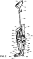
- FIG. 2 is a cross-sectional view of the vacuum cleaner 10 through line II-II FIG.1 according to one embodiment of the invention.
- the handle assembly 100 generally comprises a handgrip 119 and a user interface assembly 120.
- the user interface assembly 120 can be provided elsewhere on the vacuum cleaner 10, such as on the body assembly 200.
- handle assembly 100 further comprises a hollow handle pipe 104 that extends vertically and connects the handle assembly 100 to the body assembly 200.
- the user interface assembly 120 can be any configuration of actuating controls such as but not limited to buttons, triggers, toggles, switches, or the like, operably connected to systems in the apparatus 10 to affect and control function.
- a trigger 113 is mounted to the handgrip 119 and operably communicates with the fluid delivery system of the vacuum cleaner 10 to control fluid delivery from the vacuum cleaner 10.
- Other actuators such as a thumb switch, can be provided instead of the trigger 113.
- An upper cord wrap 103 is provided on a rear portion of the handle assembly 100.
- Body assembly 200 generally comprises a support frame to support the components of the fluid delivery system and the recovery system described for FIG. 1 .
- body assembly 200 comprises a central body 201, a front cover 203 and a rear cover 202.
- Front cover 203 can be mounted to central body 201 to form a front cavity 235.
- Rear cover 202 can be mounted to central body 201 to form a rear cavity 240.
- a motor housing assembly 250 can be mounted to an upper portion of the front cover 203.
- a carry handle 78 can be disposed on the body assembly, forwardly of the handle assembly 100, at an angle relative to the hollow handle pipe 104 to facilitate manual lifting and carrying of the multi-surface wet vacuum cleaner 10.
- Motor housing assembly 250 further comprises a cover 206 disposed beneath carry handle 78, a lower motor bracket 233, and a suction motor/fan assembly 205 positioned between the cover 206 and the motor bracket 233 in fluid communication with the dirty tank assembly 400.
- Rear cavity 240 comprises a receiving support 223 at the upper end of rear cavity 240 for receiving the clean tank assembly 300, and a pump assembly 140 beneath and in fluid communication with the clean tank assembly 300.
- Central body 201 is further provided with a lower cord wrap 255.
- Clean tank assembly 300 can be mounted to the frame 18 in any configuration.
- clean tank assembly 300 is removably mounted to the body assembly 200 such that it partially rests in the upper rear portion of the central body 201 of body assembly 200 and can be removed for filling and/or cleaning.
- Dirty tank assembly 400 can be removably mounted to the front of the body assembly 200, below the motor housing assembly 250, and is in fluid communication with the suction motor/fan assembly 205 when mounted to the vacuum cleaner 10.
- a flexible conduit hose 518 couples the dirty tank assembly 400 to the foot assembly 500 and passes through the swivel joint assembly 570.
- a heater (not shown) can be provided for heating the cleaning fluid prior to delivering the cleaning fluid to the surface to be cleaned.
- an in-line heater can be located downstream of the clean tank assembly 300, and upstream or downstream of the pump assembly 140. Other types of heaters can also be used.
- the cleaning fluid can be heated using exhaust air from a motor-cooling pathway for the suction motor/fan assembly 205.
- Foot assembly 500 comprises a removable suction nozzle assembly 580 that can be adapted to be adjacent the surface to be cleaned as the base 14 moves across the surface and is in fluid communication with dirty tank assembly 400 through flexible conduit 518.
- An agitator 546 can be provided in suction nozzle assembly 580 for agitating the surface to be cleaned.
- Some examples of agitators include, but are not limited to, a horizontally-rotating brushroll, dual horizontally-rotating brushrolls, one or more vertically-rotating brushrolls, or a stationary brush.
- a pair of rear wheels 539 are positioned for rotational movement about a central axis on the rearward portion of the foot assembly 500 for maneuvering the multi-surface wet vacuum cleaner 10 over a surface to be cleaned.
- agitator 546 can be a hybrid brushroll positioned within a brushroll chamber 565 for rotational movement about a central rotational axis, which is discussed in more detail below.
- a single brushroll 546 is illustrated; however, it is within the scope of the invention for dual rotating brushrolls to be used.
- the brushroll 546 to be mounted within the brushroll chamber 565 in a fixed or floating vertical position relative to the chamber 565.
- FIG. 3 is an exploded perspective view of the handle assembly 100.
- Handgrip 119 can comprise a front handle 101 and a back handle 102 mated fixedly to the handle pipe 104.
- the user interface assembly 120 can be provided on the front handle 101.
- the user interface assembly 120 of the illustrated embodiment comprises a control panel 111 connected to a floating key 109 and mounted with a water proof seal 108 through the front portion of front handle 101 to engage a printed circuit board assembly (PCBA) 110 and a bracket 112 provided on the back side of front handle 101.
- Bracket 112 engages a spring 114 that biases the trigger 113 mounted to the back handle 102, with a portion of the trigger 113 projecting inward in the recess formed by the mating of front handle 101 to back handle 102.
- PCBA printed circuit board assembly
- the trigger 113 can electronically communicate with the fluid delivery system.
- the trigger 113 alternatively can mechanically communicate with the fluid delivery system, such as via a push rod (not shown) that runs through the handle pipe 104.
- Hollow handle pipe 104 terminates in the frame 18 ( FIG. 1 ) by a bracket connection formed by a right bracket 106, a left bracket 105, and a female connector 107 joined together at the terminal end of handle pipe 104.
- FIG. 4 is an exploded perspective view of the body assembly 200.
- Body assembly 200 comprises front cover 203, central body 201, and rear cover 202, and terminates with a bottom cover 216.
- Front cover 203 and rear cover 202 can mount to central body 201 forming at least partially enclosed cavities 235 and 240.
- front cavity 235 generally contains electrical components such as a printed circuit board 217 (PCB) and other required circuitry 215 electrically connected to various component parts of the fluid delivery and recovery systems.
- Pump assembly 140 can comprise a connector 219, a pump 226, a clamp 220 and a gasket 218 and can be mounted in front cavity 235. Alternatively, pump assembly 140 can be mounted in rear cavity 240, or partially mounted in both front and rear cavities 235 and 240 respectively.
- the pump 226 can be a solenoid pump having a single, dual, or variable speed.
- rear cavity 240 generally contains a receiving assembly 245 for the clean tank assembly 300 ( FIG. 2 ).
- Receiving assembly 245 can comprise the receiving support 223, a spring insert 227, a clamp 224, a receiving body 222, a receiving gasket 231 and a clamp cover 225 at the upper portion of rear cavity 240 for receiving the clean tank assembly 300.
- the pump assembly 140 can be mounted beneath and in fluid communication with the receiving assembly 245.
- FIG. 5 is an exploded perspective view of the motor housing assembly 250.
- Carry handle 78 comprises a handle top 209 mounted to a handle bottom 207 with a gasket 230 mounted therebetween, and is secured to the cover 206.
- Motor housing assembly 250 can further comprise an upper motor housing body 204 and a lower motor housing body 208, and a vacuum motor cover 228 provided therebetween to partially enclose the suction motor/fan assembly 205.
- a top motor gasket 229 and a rubber gasket 221 are provided on the upper portion of the suction motor/fan assembly 205, and lower vacuum motor gaskets 210 and 211 are provided on the lower portion of the suction motor/fan assembly 205.
- a clean air outlet of the working air path through the vacuum cleaner can be defined by a left vent 213 and a right vent 214 in the lower motor housing body.
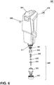
- FIG. 6 is an exploded perspective view of the clean tank assembly 300.
- Clean tank assembly 300 generally comprises at least one supply tank 301 and a supply valve assembly 320 controlling fluid flow through an outlet 311 of the supply tank 301.
- clean tank assembly 300 can include multiple supply chambers, such as one chamber containing water and another chamber containing a cleaning agent.
- a check valve 310 and a check valve umbrella 309 can be provided on supply tank 301.
- Supply valve assembly 320 mates with the receiving assembly 245 and can be configured to automatically open when seated.
- the supply valve assembly 320 includes an assembly outlet 302 that is mounted to the outlet of the fluid supply tank 301 by a threadable cap 303, a rod release insert 304 held in place with the assembly outlet 302 by an O-ring 305, and an insert spring 308 inside a spring housing 306 biasing the valve assembly 320 to a closed position.
- the valve assembly 320 When the valve assembly 320 is coupled with the receiving assembly 245, the valve assembly 320 opens to release fluid to the fluid delivery pathway.
- a screen mesh insert 307 can be provided between the tank outlet and the valve outlet to prevent particulates of a certain size from entering the pump assembly 140.
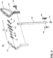
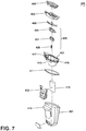
- FIG. 7 is an exploded perspective view of the dirty tank assembly 400.
- the dirty tank assembly 400 generally comprises the collection container for the fluid recovery system.
- dirty tank assembly 400 comprises a recovery tank 401 with an integral hollow standpipe 420 ( FIG. 2 ) formed therein.
- the standpipe 420 is oriented such that it is generally coincident with a longitudinal axis of the recovery tank 401.
- the standpipe 420 forms a flow path between an inlet 422 ( FIG. 2 ) formed at a lower end of the recovery tank 401 and an outlet 423 ( FIG. 2 ) on the interior of the recovery tank 401.
- the inlet 422 is aligned with the flexible conduit hose 518 to establish fluid communication between the foot assembly 500 and the recovery tank 401.
- a lid 402 sized for receipt on the recovery tank 401 supports a pleated filter 405 in a filter cover plate 403 mounted to the lid 402 with a mesh screen 406 therebetween.
- the pleated filter 405 is made of a material that remains porous when wet.
- the vacuum cleaner 10 can also be provided with one or more additional filters upstream or downstream.
- a gasket 411 positioned between mating surfaces of the lid 402 and the recovery tank 401 creates a seal therebetween for prevention of leaks.
- a shut-off valve can be provided for interrupting suction when fluid in the recovery tank 401 reaches a predetermined level.
- the shut-off valve comprises a float bracket 412 fixedly attached to a bottom wall 416 of the lid 402 in a position offset from the standpipe 420 and a moveable float 410 carried by the float bracket 412.
- the float 410 is buoyant and oriented so that the top of the float 410 can selectively seal an air outlet 415 of the recovery tank 401 leading to the downstream suction source when the fluid in the recovery tank 401 reaches a predetermined level.
- a releasable latch 430 is provided to facilitate removal of the dirty tank assembly 400 for emptying and/or cleaning, and can be positioned in an aperture 417 on a front side of the lid 402.
- the releasable latch 430 can include a latch button 407 held within a latch bracket 404 and biased with latch spring 408 toward an engaged or latched position.
- the latch button 407 releasably engages with the front cover 203 to removably secure the dirty tank assembly 400 to the body assembly 200 ( FIG. 2 ).
- a hand grip 419 can be provided on the recovery tank 401 and located below the latch 407 to facilitate handling of the dirty tank assembly 400g.
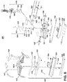
- FIG. 8 is an exploded perspective view of the foot assembly 500.
- Foot assembly 500 generally includes a housing supporting at least some of the components of the fluid delivery system and fluid recovery system.
- the housing comprises an upper cover 542 and a lower cover 501 coupled with the upper cover 542 and defining a partially enclosed cavity 561 there between for receiving at least some components of the fluid delivery and recovery pathways.
- the housing can further include a cover base 537 coupled with a lower forward portion of the lower cover to defined a portion of the brushroll chamber 565 ( FIG. 10 ).
- the upper cover 542 extends from approximately the middle to rear of foot assembly 500 and can have decorative panels 543 and 544 mounted to an upper surface.
- Upper cover 542 can be configured to releasably receive the suction nozzle assembly 580.
- Suction nozzle assembly 580 can be configured to include at least one inlet nozzle for recovering fluid and debris from the surface to be cleaned and at least one outlet for delivering fluid to the surface to be cleaned.
- suction nozzle assembly 580 can comprise a nozzle housing 551 and a nozzle cover 552 which mate to form a pair of fluid delivery channels 40 therebetween that are each fluidly connected to a spray connector 528 at one terminal end.
- a fluid dispenser 554 is configured with at least one outlet to deliver fluid to the surface to be cleaned.
- Fluid dispenser 554 may be comprised of one or more spray tips configured to deliver cleaning fluid from the fluid delivery channel 40 to the brush chamber 565.
- fluid dispenser 554 is a pair of spray tips fluidly connected to the fluid delivery channel 40.
- Spray tip 554 is mounted in the nozzle housing 551 and has an outlet in fluid communication with the brush chamber 565.
- Nozzle cover 552 can have a decorative cover 553, and one or both can be composed of a translucent or transparent material.
- Nozzle housing 551 can further comprise a front interference wiper 560 mounted at a forward position relative to the brushroll chamber 565 and disposed horizontally.
- the lower cover 501 further comprises a plurality of upstanding bosses 562 that project into cavity 561 for mounting interior components thereto.
- a rear portion of the lower cover 501 pivotally mounts to swivel joint assembly 570 for maneuvering the multi-surface wet vacuum cleaner 10 over a surface to be cleaned.
- the rear wheels 539 are positioned for rotational movement about a central axis on opposite sides of the lower cover 501 for maneuvering the multi-surface wet vacuum cleaner 10 over a surface to be cleaned.
- Swivel joint assembly 570 can be comprised of swivel joint 519, covers 520 and 521, and a swivel locking mechanism 586 for releasing the swivel joint assembly 570 for pivoting and swivel movements.
- a conduit assembly 585 is partially disposed in cavity 561 and extends through the swivel joint 519, along with the flexible conduit hose, to couple with components in the upper body assembly 200 ( FIG. 2 ).
- Conduit assembly 585 comprises a fluid supply conduit 532 and a wiring conduit 533.
- Fluid supply conduit 532 passes interiorly to swivel joint assembly 570 and fluidly connects the clean tank assembly 300 to the spray connectors 528 through a T-connector 530 having a pair spray tube connectors 531.
- Wiring conduit 533 provides a passthrough for electrical wiring from the upright assembly 12 to the base 14 through swivel joint assembly 570.
- the wiring can be used to supply electrical power to at least one electrical component in the foot assembly 500.
- an electrical component is a brush motor 503.
- an indicator light assembly includes an LED base 516 configured to mount a pair of indicator lights 517 and a pair of lenses 545 over the lights 517.
- the lights 517 may comprise light emitting diodes (LED) or other illumination sources.
- a central lower portion of the partially enclosed cavity 561 and a rearward lower portion of suction nozzle assembly 580 can be molded to form a foot conduit 564 of the fluid recovery pathway that is fluidly connected to the flexible conduit 518.
- Flexible conduit 518 fluidly connects dirty tank assembly 400 ( FIG. 2 ) to suction nozzle assembly 580.
- the brushroll 546 can be provided at a forward portion of the lower cover 501 and received in brushroll chamber 565.
- the cover base 537 rotatably receives the brushroll 546, and also mountably receives a wiper 538 positioned rearwardly of the brushroll 546.
- brushroll 546 can be configured to be removed by the user from the foot assembly 500 for cleaning and/or drying.
- a pair of forward wheels 536 are positioned for rotational movement about a central axis on the terminal surface of the cover base 537 for maneuvering the multi-surface wet vacuum cleaner 10 over a surface to be cleaned.
- the brushroll 546 can be operably coupled to and driven by a drive assembly including a dedicated brush motor 503 disposed in the cavity 561 of the lower cover 501 and one or more belts, gears, shafts, pulleys or combinations thereof to provide the coupling.
- a transmission 510 operably connects the motor 503 to the brushroll 546 for transmitting rotational motion of a motor shaft 505 to the brushroll 546.
- transmission 510 can include a drive belt 511 and one or more gears, shafts, pulleys, or combinations thereof.
- a single motor/fan assembly (not shown) can provide both vacuum suction and brushroll rotation in the multi-surface wet vacuum cleaner 10.
- a brush motor exhaust tube 515 can be provided to the brush motor 503 and configured to exhaust air to the outside of the multi-surface wet vacuum cleaner 10.
- FIG. 9 is a perspective view of the hybrid brushroll 546.
- Hybrid brushroll 546 is suitable for use on both hard and soft surfaces, and for wet or dry vacuum cleaning.
- brushroll 546 comprises a dowel 46, a plurality of tufted bristles 48 or unitary bristle strips extending from the dowel 46, and microfiber material 49 provided on the dowel 46, arranged between the bristles 48.
- Dowel 46 can be constructed of a polymeric material such as acrylonitrile butatdiene styrene (ABS), polypropylene or styrene, or any other suitable material such as plastic, wood, or metal.
- Bristles 48 can be tufted or unitary bristle strips and constructed of nylon, or any other suitable synthetic or natural fiber.
- the microfiber material 49 can be constructed of polyester, polyamides, or a conjugation of materials including polypropylene or any other suitable material known in the art from which to construct microfiber.
- dowel 46 is constructed of ABS and formed by injection molding in one or more parts. Bristle holes (not shown) can be formed in the dowel 46 by drilling into the dowel 46 after molding, or can be integrally molded with the dowel 46.
- the bristles 48 are tufted and constructed of nylon with a 0.15mm diameter.
- the bristles 48 can be assembled to the dowel 46 in a helical pattern by pressing bristles 48 into the bristle holes and securing the bristles 48 using a fastener (not shown), such as, but not limited to, a staple, wedge, or anchor.
- the microfiber material 49 is constructed of multiple strips of polyester treated with Microban ⁇ and glued onto the dowel 46 between bristles 48.
- one continuous microfiber strip 49 can be used and sealed by hot wire to prevent the single strip from detaching from the dowel 46.
- the polyester material can be 7-14 mm thick with weight of 912 g/m 2 .
- the polyester material can be an incipient absorption of 269 wt% and a total absorption of 1047 wt%.
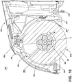
- FIG. 10 is a close-up sectional view through a forward section of the suction nozzle assembly 580.
- the brushroll 546 is positioned for rotational movement in a direction R about a central rotational axis X.
- the suction nozzle assembly 580 includes a suction nozzle 594 defined within the brush chamber 565 that is in fluid communication with the foot conduit 564 and configured to extract liquid and debris from the brushroll 546 and the surface to be cleaned.
- the suction nozzle 594 defines a dirty air inlet of the working air path or recovery pathway through the vacuum cleaner.
- Suction nozzle 594 is further fluidly connected through the foot conduit 564 and the flexible hose conduit 518, to dirty tank assembly 400 (see FIG. 16B ).
- Front interference wiper 560 mounted at a forward position of the nozzle housing 551, is provided in the brush chamber 565, and is configured to interface with a leading portion of the brushroll 546, as defined by the direction of rotation R of the brushroll 546.
- Spray tips 554 are mounted to the nozzle housing 551 with an outlet in the brushroll chamber 565 and oriented to spray fluid inwardly onto the brushroll 546.
- the wetted portion brushroll 546 then rotates past the interference wiper 560, which scrapes excess fluid off the brushroll 546, before reaching the surface to be cleaned.
- Rear wiper squeegee 538 is mounted to the cover base 537 behind the brushroll 546 and is configured to contact the surface as the base 14 moves across the surface to be cleaned.
- the rear wiper squeegee 538 wipes residual liquid from the surface to be cleaned so that it can be drawn into the fluid recovery pathway via the suction nozzle 594, thereby leaving a moisture and streak-free finish on the surface to be cleaned.
- Front interference wiper 560 and rear wiper 538 can be squeegees constructed of a polymeric material such as polyvinyl chloride, a rubber copolymer such as nitrile butadiene rubber, or any material known in the art of sufficient rigidity to remain substantially undeformed during normal use of the vacuum cleaner 10, and can be smooth or optionally comprise nubs on the ends thereof.
- Wiper 560 and wiper 538 can be constructed of the same material in the same manner or alternatively constructed of different materials providing different structure characteristics suitable for function.
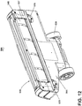
- FIG. 11 is a perspective view of the underside of the suction nozzle assembly 580, with some portions cut away to show some internal features of the suction nozzle assembly 580.
- Brushroll chamber 565 is defined on the underside of suction nozzle assembly 580 forward of the foot conduit 564.
- a pair of spray tip outlets 595 can be provided in the brush chamber 565.
- a latch mechanism 587 is provided at the rearward portion of suction nozzle assembly 580 and is configured to be received in the upper cover 542 ( FIG. 8 ).
- Latch mechanism 587 can be received in a latch receiving depression 587a ( FIG. 8 ) provided on the upper cover 542 base 14 and is configured for a user to remove and/or lock the suction nozzle assembly 580 onto the base 14.
- the suction nozzle assembly 580 can be biased by springs 556 to release suction nozzle assembly 580 away from foot assembly 500 when the latch mechanism 587 is actuated.
- a pair of spray connector inlets 590 are provided on the underside of nozzle housing 551 and are fluidly connected to the first terminal end of fluid delivery channels 40 on the upper side of the nozzle housing 551 ( FIG. 8 ).
- Front interference wiper 560 is provided in the forwardmost portion of brushroll chamber 565.
- FIG. 12 is a bottom perspective view of the foot assembly 500.
- Rear wiper 538 is provided on the cover base 537, rearward of brushroll 546, and configured to contact the surface to be cleaned.
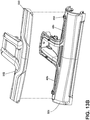
- FIG. 13A is a perspective view of the underside of the nozzle cover 552 and FIG. 13B is an exploded perspective view of the suction nozzle assembly 580.
- the nozzle cover 552 is comprised of two fluid channel portions 40a that form an upper portion of the flow channels 40 when mated with nozzle housing 551.
- the nozzle housing 551 comprises two fluid channel portions 40b that form lower portions of the flow channels 40 when mated with the nozzle cover 552. Fluid channel portions 40a and 40b mate to form the fluid delivery flow channels 40 therebetween containing the spray tips 554 at the second terminal ends partially therein.
- the nozzle housing 551 can define a lens for the brush chamber 565 and can be comprised of a translucent or transparent material to allow the brushroll 546 to be viewed therethough.
- the nozzle cover 552 can define a lens cover, and can be comprised of a translucent or transparent material, which permits a user to view the flow of fluid through the flow channels 40.
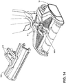
- FIG. 14 is a partially exploded view of the base.
- suction nozzle assembly 580 is removed to expose the indicator lights 517.
- the indicator lights 517 can be configured to activate in combination with the pump assembly 140 when trigger 113 is depressed to deliver fluid ( FIG. 2 ).
- a portion of the base can form a light tube or light pipe 578 that is illuminated by the indicator lights 517 when fluid is delivered, indicating to the user that fluid is being delivered to the surface underneath the base 14.
- the light pipe 578 can be any physical structure capable of transporting or distributing light from the indicator lights 517.
- the light pipe 578 can be a hollow structure that contain the light with a reflective lining, or a transparent solid structure that contain the light by total internal reflection.
- light pipes 578 are solid structures formed on the suction nozzle assembly 580 and are elongated to extend along the fluid delivery channels 40 and configured to distribute of light over its length. More specifically, the light pipes 578 are embodied as raised rails molded onto the surface of the nozzle cover 552, generally above the fluid delivery channels 40.
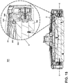
- FIG. 15 is a cross-sectional view of the foot assembly 500 through line XV-XV of FIG. 1 , with portion A enlarged for a close up view of a fluid dispenser in the form of the spray tip 554.
- the spray tip 554 is mounted in each of the terminal ends of each of the fluid delivery flow channels 40 of the suction nozzle assembly 580 and can be configured to terminate in the brush chamber 565.
- Each spray tip 554 includes an orifice 595 oriented to spray onto the brushroll 546 as depicted by the solid arrows in FIG. 15 .
- the spray tips 554 can be oriented to spray along a horizontal axis which may be parallel to the rotational axis X of the brushroll 546 or at a substantially horizontal angle relative to the rotational axis X in order to wet the entire length of the brushroll 546 during fluid dispensing.
- substantially horizontal the angle of spray of the orifice 595 can be 0 to 30 degrees, depending on the length of the brushroll and the spacing of the spray tips 554 in order to cover the entire brushroll 546 with fluid.
- the angle of the spray tips 554 may be static or adjustable while the multi-surface wet vacuum cleaner 10 is in operation or prior to operation.
- the spray tip outlet orifice 595 can have any diameter suitable to deliver fluid at the desired pressure, pattern, and/or volume from the spray tip 554.
- spray tips 554 have an outlet orifice diameter of 1.0mm and are oriented to spray inwardly onto a top of the brushroll 546 at an angle of 15 degrees from the horizontal.
- FIG. 16A is a schematic diagram of a fluid supply pathway of the vacuum cleaner 10.
- the arrows present designate the directional flow of fluid in the fluid supply pathway according to the present example.
- the fluid supply pathway can include the supply tank 301 for storing a supply of fluid.
- the fluid can comprise one or more of any suitable cleaning fluids, including, but not limited to, water, compositions, concentrated detergent, diluted detergent, etc., and mixtures thereof.
- the fluid can comprise a mixture of water and concentrated detergent.
- the fluid supply pathway can further comprise a flow control system 705 for controlling the flow of fluid from the supply tank 301 to fluid supply conduit 532.
- the flow control system 705 can comprise pump 226, which pressurizes the system, and supply valve assembly 320, which controls the delivery of fluid to the fluid supply conduit 532.
- fluid flows from the supply tank 301, through pump 226, to the fluid supply conduit 532.
- a drain tube 706 provides a pathway for draining any fluid that may leak from the supply tank 301 while the vacuum cleaner 10 is not in active operation to a drain hole (not pictured) in foot assembly 500 to collect in a storage tray 900 ( FIG. 19 ). From the fluid supply conduit 532, fluid flows sequentially through the spray connectors 528, through the fluid delivery channels 40, through the spray tips 554, and onto the brushroll 546 ( FIG. 15 ), which applies the fluid to the surface to be cleaned.
- the trigger 113 ( FIG. 2 ) can be depressed to actuate the flow control system 705 and dispense fluid to the fluid dispenser 554.
- the trigger 113 can be operably coupled to the supply valve 320 such that pressing the trigger 113 will open the valve 320.
- the valve 320 can be electrically actuated, such as by providing an electrical switch between the valve 320 and a power source 22 ( FIG. 18 ) that is selectively closed when the trigger 113 is pressed, thereby powering the valve 320 to move to an open position.
- the valve 320 can be a solenoid valve.
- the pump 226 can also be coupled with the power source 22.
- the pump 226 can be a centrifugal pump.
- the pump 226 can be a solenoid pump.
- the pump 226 can be eliminated and the flow control system 705 can comprise a gravity-feed system having a valve fluidly coupled with an outlet of the supply tank(s) 301, whereby when valve is open, fluid will flow under the force of gravity to the fluid dispenser 554.
- the valve 320 can be mechanically actuated or electrically actuated, as described above.
- FIG. 16B is a schematic diagram of a fluid recovery pathway of the vacuum cleaner 10.
- the arrows present designate the directional flow of fluid in the fluid recovery pathway.
- the fluid recovery pathway can include the suction nozzle assembly 580, the foot conduit 564, the flexible conduit hose 518, the suction motor/fan assembly 205 in fluid communication the suction nozzle assembly 580 for generating a working air steam, and recovery tank 401 for separating and collecting fluid and debris from the working airstream for later disposal.
- Standpipe 420 can be formed in a portion of recovery tank 401 for separating fluid and debris from the working airstream.
- the suction motor/fan assembly 205 provides a vacuum source in fluid communication with the suction nozzle assembly 580 to draw the fluid and debris from the surface to be cleaned through the flexible hose conduit 518 to the recovery tank 401.
- FIG. 17 is a rear perspective view of the vacuum cleaner 10 with portions removed to show the conduit assembly 585.
- flexible conduit hose 518 couples dirty tank assembly 400 to foot assembly 500 through a forward portion of pivotable swivel joint assembly 570.
- Fluid supply conduit 532 and wiring conduit 533 can be provided rearward of flexible conduit hose 518. Fluid supply conduit 532 fluidly couples the pump 226 the T-connector 530 in the foot assembly 500.
- FIG. 18 is a schematic circuit diagram of the vacuum cleaner 10.
- User interface assembly 120 can be operably connected to the various components of cleaner 10 directly or through a central control unit 750.
- User interface assembly 120 can comprise one or more actuators and be configured with any combination of buttons, switches, toggles, triggers, or the like to allow a user to select multiple cleaning modes and/or control the fluid delivery and recovery systems.
- a power source 22, such as a battery or power cord plugged into a household outlet, can be electrically coupled to the electrical components of the vacuum cleaner 10, including the motors 205, 503 and pump 226.
- a suction power switch 25 between the suction motor/fan assembly 205 and the power source 22 can be selectively closed by the user, thereby activating the suction motor/fan assembly 205.
- a brush power switch 27 between the brush motor 503 and the power source 22 can be selectively closed by the user, thereby activating the brush motor 503.
- User interface assembly 120 can be operably coupled to the pump 226 such that an actuator, such as trigger 113, can activate the pump 226 when engaged, thereby powering the pump 226 to deliver fluid to the fluid supply pathway.
- Actuation of the pump 226 can be operably connected to the LED lights 517 such that actuation of trigger 113 additionally powers LED indicator lights 517 to provide user feedback that fluid is being delivered to the fluid supply pathway.
- user interface assembly 120 of vacuum cleaner 10 can be provided with actuators 122 for selecting multiple cleaning modes to be selected by the user.
- Actuators 122 send a signal to the central control unit 750, which can include a PCBA.
- the output from the central control unit 750 adjusts the frequency of the solenoid pump 226 to generate the desired flow rate depending on the mode selected.
- the vacuum cleaner 10 can have a hard floor cleaning mode and a carpet cleaning mode. In the hard floor cleaning mode, the liquid flow rate to the fluid dispenser 554 is less than in the carpet cleaning mode. The liquid flow rate is controlled by the speed of the pump 226.
- the speed of the pump 226 is controlled in the hard floor cleaning mode so that the liquid flow rate is approximately 50ml/min and the speed of the pump 226 is controlled in the carpet cleaning mode so that the liquid flow rate is approximately 100ml/min.
- the vacuum cleaner 10 can have a wet scrubbing mode in which the suction motor/fan assembly 205 can be inoperative while brush motor 503 is activated so that the soiled cleaning solution is not removed from the surface to be cleaned.
- FIG. 19 is a perspective view of a storage tray 900 for the vacuum cleaner 10.
- Storage tray 900 can be configured to receive the base 14 of the vacuum cleaner 10 in an upright, stored position.
- Storage tray 900 can optionally be adapted to contain a liquid for the purposes of cleaning the interior parts of cleaner 10 and/or receiving liquid from the drain tube 706 ( FIG. 16A ).
- storage tray 900 is adapted to receive the base 14 and comprises a removable brushroll holder 905 provided on an exterior side wall of the tray 900.
- storage tray 900 can be configured with an integral brushroll holder 905.
- the brushroll holder 905 can be secured to the storage tray 900 by a retention latch 910.
- Retention latch 910 can include a sliding lock, clamp, brace, or any other mechanism in which to secure brushroll holder 905 to its position on storage tray 900 while in use and can be biased or otherwise configured to allow a user to release a lock and remove the brushroll holder 905 from storage tray 900.
- Brushroll holder 905 can be adapted to removably receive one or more brushrolls 546 for the purposes of storage and/or drying.
- Brushroll holder 905 can comprise one or more brushroll slots 915 to securely receive brushrolls 546 in a vertical fixed position for drying and storage.
- Brushroll slots 915 can be fixed or adjustable and can be comprised of clamps, rods, or molded receiving positions that can accommodate brushroll 546 with or without the dowel 46 inserted.
- brushroll holder 905 can comprise a series of horizontal storage positions such racks, hooks, or clamps (not shown) to secure brushrolls 546 in a horizontal position.
- the multi-surface wet vacuum cleaner 10 shown in the figures can be used to effectively remove debris and fluid from the surface to be cleaned in accordance with the following method.
- the sequence of steps discussed is for illustrative purposes only and is not meant to limit the method in any way as it is understood that the steps may proceed in a different logical order, additional or intervening steps may be included, or described steps may be divided into multiple steps, without detracting from the invention.
- the multi-surface wet vacuum cleaner 10 is prepared for use by coupling the vacuum cleaner 10 to the power source 22, and by filling the supply tank 301 with cleaning fluid.
- a user selects the floor surface type to be cleaned through user interface assembly 120.
- Cleaning fluid is selectively delivered to the surface to be cleaned via the fluid supply pathway by user-activation of the trigger 113, while the vacuum cleaner 10 is moved back and forth over the surface.
- Pump 226 can be activated by user interface assembly 120.
- User-activation of trigger 113 activates the pump 226 and fluid is released by clean tank assembly 300 into the fluid delivery pathway through spray tips 554 and onto brushroll 546. The wetted brushroll 546 is wiped across the surface to be cleaned to remove dirt and debris present on the surface.
- Activation of the trigger 113 also simultaneously activates LED indicator lights 517 which transmit light through the LED lenses 545 and into nozzle cover 552 along the light pipes 578 to provide an illuminated indication that fluid is being dispensed.
- the illumination of the LEDs 517 and light pipes 578 indicate to the user the fluid dispenser 554 has been activated and fluid has been dispensed onto the surface to be cleaned.
- brush power switch 27 can activate brushroll 546 to agitate or rotate cleaning fluid into the surface to be cleaned. Such interaction removes the adhered dirt, dust, and debris, which then become suspended in the cleaning fluid.
- front interference squeegee 560 confronts brushroll 546 in a manner so as to ensure the brush is wetted evenly and cleaning fluid is spread uniformly across the entire length of the brushroll 546.
- Front interference squeegee 560 can also be configured to simultaneously scrape soiled fluid and debris off the brushroll 546 to be drawn into the suction nozzle assembly 580 and fluid recovery pathway.
- the suction motor/fan assembly 205 can be inoperative which facilitates a wet scrubbing mode so that the soiled cleaning solution is not removed as the cleaner 10 is moved back and forth across the surface to be cleaned.
- the fluid and debris-laden working air passes through the suction nozzle assembly 580 and into the downstream recovery tank 401 where the fluid debris is substantially separated from the working air.
- the airstream then passes through the suction motor/fan assembly 205 prior to being exhausted from the vacuum cleaner 10 through the clean air outlet defined by the vents 213, 214.
- the recovery tank 401 can be periodically emptied of collected fluid and debris by actuating the latch 430 and removing the dirty tank assembly 400 from the body assembly 200.
- the vacuum cleaner 10 When operation has ceased, the vacuum cleaner 10 can be locked upright and placed into the storage tray 900 for storage or cleaning. If needed, the suction nozzle assembly 580 can be removed from the foot assembly 500. Brushroll 546 can then be removed from the foot assembly 500 and placed in brushroll holder 905.
- the multi-surface wet vacuum cleaner 10 can optionally be provided with a self-cleaning mode.
- the self-cleaning mode can be used to clean the brushroll and internal components of the fluid recovery pathway of vacuum cleaner 10.
- the multi-surface wet vacuum cleaner 10 is prepared for cleaning by coupling the vacuum cleaner 10 to the power source 22, and by filling the storage tray 900 to a predesignated fill level with a cleaning fluid or water.
- the user selects the designated cleaning mode from the user interface assembly 120.
- locking mechanism 586 is released to pivot upright assembly 12 rearward and the hard floor cleaning mode is selected from the user interface assembly 120 by the user.
- Brushroll 546 is activated by brush motor 503 while suction motor/fan assembly 205 provides suction to the suction nozzle assembly 580 which draws fluid in storage tray 900 and into the fluid recovery pathway for a predetermined amount of time or until the fluid in storage tray 900 has been depleted.
- vacuum cleaner 10 can be returned to the upright and locked position in storage tray 900 and brushroll 546 can be removed and stored as previously described.
- the different features and structures of the various embodiments of the invention may be used in combination with each other as desired, or may be used separately. That one vacuum cleaner is illustrated herein as having all of these features does not mean that all of these features must be used in combination, but rather done so here for brevity of description.
- the vacuum cleaner 10 shown herein has an upright configuration, the vacuum cleaner can be configured as a canister or portable unit.
- foot components such as the suction nozzle assembly 580 and brushroll 546 can be provided on a cleaning head coupled with a canister unit.
- the vacuum cleaner can additionally have steam delivery capability.
- the various features of the different embodiments may be mixed and matched in various vacuum cleaner configurations as desired to form new embodiments, whether or not the new embodiments are expressly described.
Landscapes
- Engineering & Computer Science (AREA)
- Mechanical Engineering (AREA)
- Nozzles For Electric Vacuum Cleaners (AREA)
- Cleaning By Liquid Or Steam (AREA)
Claims (15)
- Appareil de nettoyage de surface (10), comprenant un boîtier comprenant un ensemble poignée (12) vertical et une base (14) montée sur l'ensemble poignée (12) et conçu pour se déplacer sur une surface à nettoyer, une source d'aspiration (205), un ensemble buse d'aspiration (580) situé sur la base (14) et définissant une buse d'aspiration (594) en communication fluidique avec la source d'aspiration (205), l'ensemble buse d'aspiration (580) comprenant un boîtier de buse (551) et un couvercle (552) sur le boîtier de buse (551), et un système de distribution de fluide situé sur le boîtier et comprenant une chambre d'alimentation en fluide (301) conçue pour contenir une alimentation en liquide, un distributeur de fluide (554) situé sur la base (14) en communication fluidique avec la chambre d'alimentation en fluide (301), et un chemin de distribution de fluide entre la chambre d'alimentation en fluide (301) et le distributeur de fluide (554) ; caractérisé par :un rouleau-brosse hybride (546) qui comprend plusieurs matériaux d'agitation pour optimiser les performances de nettoyage sur différents types de surfaces à nettoyer, y compris les surfaces dures et souples, et pour différents modes de nettoyage, y compris le nettoyage par aspiration humide et sèche,le rouleau-brosse hybride (546) convenant à la fois aux surfaces dures et souples, et au nettoyage par aspiration humide et sèche, etle rouleau-brosse hybride (546) comprenant une cheville (46), une pluralité de poils touffetés (48) s'étendant à partir de la cheville (46), et un matériau en microfibres (49) situé sur la cheville et disposé entre les poils (48).
- Appareil de nettoyage de surface (10) selon la revendication 1, la cheville (46) comprenant un matériau polymère, du bois et/ou du métal.
- Appareil de nettoyage de surface (10) selon l'une quelconque des revendications 1 ou 2, la pluralité de poils touffetés (48) comprenant des fibres synthétiques et/ou naturelles.
- Appareil de nettoyage de surface (10) selon l'une quelconque des revendications 1 à 3, le matériau en microfibres (49) comprenant du polyester, des polyamides et/ou du polypropylène.
- Appareil de nettoyage de surface (10) selon l'une quelconque des revendications 1 à 4, et comprenant en outre au moins un canal de distribution de fluide (40) formant une partie du chemin de distribution de fluide, l'au moins un canal de distribution de fluide (40) étant formé entre le boîtier de buse (551) et le couvercle (552).
- Appareil de nettoyage de surface (10) selon l'une quelconque des revendications 1 à 5, et comprenant en outre un actionneur (113) situé sur l'ensemble poignée (12) vertical et accouplé fonctionnellement au système de distribution de fluide pour délivrer du fluide au distributeur de fluide (554) par l'intermédiaire du chemin de distribution de fluide.
- Appareil de nettoyage de surface (10) selon l'une quelconque des revendications 1 à 6, la base (14) comprenant une chambre à brosse (565) et le rouleau-brosse hybride (546) étant monté en son sein, et le distributeur de fluide (554) étant situé dans la chambre à brosse (565) pour distribuer du fluide sur le rouleau-brosse hybride (546) et/ou la surface à nettoyer.
- Appareil de nettoyage de surface (10) selon la revendication 7, le rouleau-brosse hybride (546) étant monté dans une position verticale flottante par rapport à la chambre à brosse (565).
- Appareil de nettoyage de surface (10) selon l'une quelconque des revendications 7 ou 8, le rouleau-brosse hybride (546) comprenant un rouleau-brosse hybride (546) double monté dans la chambre à brosse (565).
- Appareil de nettoyage de surface (10) selon l'une quelconque des revendications 7 à 9, un racleur d'interférence (560) étant positionné sur un côté avant de la chambre à brosse (565) et conçu pour assurer l'interface avec une partie avant du rouleau-brosse hybride (546) avant la rotation de la partie avant en contact avec la surface à nettoyer.
- Appareil de nettoyage de surface (10) selon l'une quelconque des revendications 1 à 10, et comprenant en outre une raclette (538) située sur la base (14) à l'arrière du rouleau-brosse hybride (546) et conçue pour entrer en contact avec la surface à nettoyer lorsque la base (14) se déplace sur la surface à nettoyer.
- Appareil de nettoyage de surface (10) selon l'une quelconque des revendications 7 à 10, le distributeur de fluide (554) comprenant au moins un embout de pulvérisation ayant un orifice de sortie (595) dans la chambre à brosse (565), et l'orifice de sortie (595) étant orienté pour pulvériser du fluide vers l'intérieur sur le rouleau-brosse hybride (546), sensiblement le long d'un axe du rouleau-brosse hybride (546).
- Appareil de nettoyage de surface (10) selon la revendication 12, l'orifice de sortie (595) étant conçu pour diriger un jet de liquide à environ 15 degrés de l'horizontale, l'horizontale étant définie par l'axe du rouleau-brosse hybride (546).
- Appareil de nettoyage de surface (10) selon l'une quelconque des revendications 1 à 13, le distributeur de fluide (554) comprenant un premier embout de pulvérisation (554) monté dans la base (14) et ayant une première sortie (595) et un second embout de pulvérisation (554) monté dans la base (14) et ayant une seconde sortie (595), les première et seconde sorties étant orientées dans des directions opposées pour pulvériser le fluide vers l'intérieur sur le rouleau-brosse hybride (546).
- Appareil de nettoyage de surface (10) selon la revendication 5, le boîtier de buse (551) comprenant une lentille pour une chambre à brosse (565) de la base (14) qui comprend un matériau translucide ou transparent qui permet à un utilisateur de voir le rouleau-brosse hybride (546) dans la chambre à brosse (565) à travers la lentille, et le couvercle (552) comprenant un matériau translucide ou transparent qui permet à un utilisateur de voir un écoulement de fluide à travers les canaux de distribution de fluide (40) intégrés.
Priority Applications (1)
| Application Number | Priority Date | Filing Date | Title |
|---|---|---|---|
| PL18211523T PL3491986T3 (pl) | 2015-10-28 | 2016-10-27 | Urządzenie do czyszczenia powierzchni |
Applications Claiming Priority (2)
| Application Number | Priority Date | Filing Date | Title |
|---|---|---|---|
| US201562247503P | 2015-10-28 | 2015-10-28 | |
| EP16195963.0A EP3162262B1 (fr) | 2015-10-28 | 2016-10-27 | Appareil de nettoyage de surface |
Related Parent Applications (2)
| Application Number | Title | Priority Date | Filing Date |
|---|---|---|---|
| EP16195963.0A Division EP3162262B1 (fr) | 2015-10-28 | 2016-10-27 | Appareil de nettoyage de surface |
| EP16195963.0A Division-Into EP3162262B1 (fr) | 2015-10-28 | 2016-10-27 | Appareil de nettoyage de surface |
Publications (2)
| Publication Number | Publication Date |
|---|---|
| EP3491986A1 EP3491986A1 (fr) | 2019-06-05 |
| EP3491986B1 true EP3491986B1 (fr) | 2020-06-17 |
Family
ID=57208207
Family Applications (9)
| Application Number | Title | Priority Date | Filing Date |
|---|---|---|---|
| EP20187821.2A Active EP3763269B1 (fr) | 2015-10-28 | 2016-10-27 | Appareil de nettoyage de surface |
| EP18199079.7A Active EP3466311B1 (fr) | 2015-10-28 | 2016-10-27 | Appareil de nettoyage de surface |
| EP18211523.8A Revoked EP3491986B1 (fr) | 2015-10-28 | 2016-10-27 | Appareil de nettoyage de surface |
| EP20217412.4A Revoked EP3834690B1 (fr) | 2015-10-28 | 2016-10-27 | Appareil de nettoyage de surface |
| EP20187822.0A Active EP3766397B8 (fr) | 2015-10-28 | 2016-10-27 | Appareil de nettoyage de surface |
| EP16195963.0A Active EP3162262B1 (fr) | 2015-10-28 | 2016-10-27 | Appareil de nettoyage de surface |
| EP20217408.2A Active EP3834689B1 (fr) | 2015-10-28 | 2016-10-27 | Appareil de nettoyage de surface |
| EP23182000.2A Pending EP4252609A3 (fr) | 2015-10-28 | 2016-10-27 | Appareil de nettoyage de surfaces |
| EP20210305.7A Active EP3815592B1 (fr) | 2015-10-28 | 2016-10-27 | Appareil de nettoyage de surface |
Family Applications Before (2)
| Application Number | Title | Priority Date | Filing Date |
|---|---|---|---|
| EP20187821.2A Active EP3763269B1 (fr) | 2015-10-28 | 2016-10-27 | Appareil de nettoyage de surface |
| EP18199079.7A Active EP3466311B1 (fr) | 2015-10-28 | 2016-10-27 | Appareil de nettoyage de surface |
Family Applications After (6)
| Application Number | Title | Priority Date | Filing Date |
|---|---|---|---|
| EP20217412.4A Revoked EP3834690B1 (fr) | 2015-10-28 | 2016-10-27 | Appareil de nettoyage de surface |
| EP20187822.0A Active EP3766397B8 (fr) | 2015-10-28 | 2016-10-27 | Appareil de nettoyage de surface |
| EP16195963.0A Active EP3162262B1 (fr) | 2015-10-28 | 2016-10-27 | Appareil de nettoyage de surface |
| EP20217408.2A Active EP3834689B1 (fr) | 2015-10-28 | 2016-10-27 | Appareil de nettoyage de surface |
| EP23182000.2A Pending EP4252609A3 (fr) | 2015-10-28 | 2016-10-27 | Appareil de nettoyage de surfaces |
| EP20210305.7A Active EP3815592B1 (fr) | 2015-10-28 | 2016-10-27 | Appareil de nettoyage de surface |
Country Status (10)
| Country | Link |
|---|---|
| US (18) | US10092155B2 (fr) |
| EP (9) | EP3763269B1 (fr) |
| CN (1) | CN206434268U (fr) |
| AU (5) | AU2016101847B4 (fr) |
| CZ (8) | CZ35717U1 (fr) |
| DE (8) | DE202016009036U1 (fr) |
| ES (6) | ES2914518T3 (fr) |
| MX (1) | MX366663B (fr) |
| PL (5) | PL3466311T3 (fr) |
| PT (5) | PT3491986T (fr) |
Cited By (1)
| Publication number | Priority date | Publication date | Assignee | Title |
|---|---|---|---|---|
| US11484172B1 (en) | 2021-12-03 | 2022-11-01 | Sharkninja Operating Llc | Wet dry appliance |
Families Citing this family (139)
| Publication number | Priority date | Publication date | Assignee | Title |
|---|---|---|---|---|
| CN108903776B (zh) | 2013-12-12 | 2020-12-04 | 阿尔弗雷德·卡赫欧洲两合公司 | 地面清洁机 |
| AU2016101847B4 (en) | 2015-10-28 | 2022-02-17 | Bissell Inc. | Surface cleaning apparatus |
| US10299654B2 (en) * | 2016-02-02 | 2019-05-28 | Eric Rawet | Fluid suction device |
| DE102016111810A1 (de) * | 2016-06-28 | 2017-12-28 | Vorwerk & Co. Interholding Gmbh | Feuchtreinigungsgerät mit einer um eine Walzenachse rotierbaren Reinigungswalze |
| AU2017101395A4 (en) | 2016-11-01 | 2017-11-16 | Bissell Inc. | Handheld extraction cleaner |
| AU2017101723A4 (en) | 2016-12-16 | 2018-01-18 | Bissell Inc. | Surface cleaning apparatus |
| USD876036S1 (en) | 2017-05-17 | 2020-02-18 | Tti (Macao Commercial Offshore) Limited | Floor cleaner |
| AU2018203547B2 (en) | 2017-06-02 | 2023-09-28 | Bissell Inc. | Self-cleaning system and method for extraction cleaners |
| DE102017118226A1 (de) | 2017-08-10 | 2019-02-14 | Vorwerk & Co. Interholding Gmbh | Bodenbearbeitungsgerät mit mehreren Tanks zur Bevorratung von Flüssigkeit |
| US10575701B2 (en) | 2017-09-15 | 2020-03-03 | Omachron Intellectual Property Inc. | Surface cleaning apparatus |
| CN107661073A (zh) * | 2017-11-07 | 2018-02-06 | 浙江菲力普电气有限公司 | 一种洗地机 |
| CN107969986B (zh) * | 2017-11-07 | 2023-08-08 | 武文扬 | 一种浴室皮屑清理装置 |
| US20190133398A1 (en) * | 2017-11-09 | 2019-05-09 | Rug Doctor, LLC | Liquid extraction apparatus and method |
| US10512383B2 (en) | 2017-11-30 | 2019-12-24 | Bissell Homecare, Inc. | Surface cleaning apparatus |
| EP3723601B1 (fr) | 2017-12-14 | 2024-03-06 | Fluidda Respi NV | Outil de criblage pour des patients souffrant d'affections pulmonaires |
| PL3501363T3 (pl) * | 2017-12-21 | 2021-04-19 | Bissell Homecare, Inc. | Urządzenie do czyszczenia powierzchni |
| CN110785638A (zh) * | 2018-02-13 | 2020-02-11 | 深圳市赫兹科技有限公司 | 污水收集检测机构及清洗装置 |
| CN110192818A (zh) * | 2018-02-26 | 2019-09-03 | 江苏美的清洁电器股份有限公司 | 表面清洁装置及其控制方法 |
| PL3656270T3 (pl) | 2018-03-05 | 2021-11-22 | Bissell Inc. | Odkurzacz ekstrakcyjny |
| CN209951166U (zh) * | 2018-03-30 | 2020-01-17 | 无锡家易洁电器科技有限公司 | 一种扫拖一体机 |
| US11039722B2 (en) * | 2018-04-23 | 2021-06-22 | Sharkninja Operating Llc | Assisted drive for surface cleaning devices |
| USD917814S1 (en) * | 2018-04-25 | 2021-04-27 | Lupe Technology Limited | Vacuum cleaner |
| USD876736S1 (en) * | 2018-04-30 | 2020-02-25 | Toshiba Lifestyle Products & Services Corporation | Vacuum cleaner |
| CN108703719A (zh) * | 2018-05-29 | 2018-10-26 | 宁波富佳实业有限公司 | 一种集成式清洁装置 |
| KR20210016050A (ko) | 2018-06-22 | 2021-02-10 | 비쎌 인코포레이티드 | 표면을 청소하기 위한 장치 |
| JP2021104341A (ja) * | 2018-06-22 | 2021-07-26 | ビッセル インク. | 表面掃除機及びトレー |
| KR20210019053A (ko) * | 2018-06-22 | 2021-02-19 | 비쎌 인코포레이티드 | 표면 청소 장치 및 트레이 |
| USD869798S1 (en) * | 2018-06-28 | 2019-12-10 | Shenzhen Haohongyuan Technology Co., Ltd. | Vacuum cleaner |
| KR102081706B1 (ko) * | 2018-07-18 | 2020-02-27 | 세메스 주식회사 | 기판 처리 방법 및 기판 처리 장치 |
| USD906609S1 (en) * | 2018-07-31 | 2020-12-29 | Sharkninja Operating Llc | Vacuum body for a vacuum cleaner |
| CN109171549A (zh) * | 2018-08-03 | 2019-01-11 | 珠海格力电器股份有限公司 | 一种具有喷水功能的清洁头及具有该清洁头的湿式吸尘器 |
| CN108670120B (zh) * | 2018-08-17 | 2023-12-22 | 天佑电器(苏州)有限公司 | 吸尘器 |
| US20200060494A1 (en) * | 2018-08-27 | 2020-02-27 | Tti (Macao Commercial Offshore) Limited | Floor cleaner |
| US11627856B2 (en) * | 2018-08-27 | 2023-04-18 | Techtronic Floor Care Technology Limited | Floor cleaner |
| US11889960B2 (en) | 2018-08-27 | 2024-02-06 | Techtronic Floor Care Technology Limited | Floor cleaner |
| CN112351715A (zh) * | 2018-08-27 | 2021-02-09 | 创科地板护理技术有限公司 | 地面清洁器 |
| US10820762B2 (en) * | 2018-08-27 | 2020-11-03 | Tti (Macao Commercial Offshore) Limited | Floor cleaner |
| AU2019327393B2 (en) * | 2018-08-27 | 2022-07-21 | Techtronic Floor Care Technology Limited | Floor cleaner |
| US11291345B2 (en) | 2018-08-27 | 2022-04-05 | Techtronic Floor Care Technology Limited | Floor cleaner |
| AU2019327392B2 (en) * | 2018-08-27 | 2022-03-03 | Techtronic Floor Care Technology Limited | Floor cleaner |
| US11284767B2 (en) | 2018-08-29 | 2022-03-29 | Bissell Inc. | Surface cleaning apparatus |
| EP3787465B1 (fr) * | 2018-09-21 | 2023-09-13 | Techtronic Floor Care Technology Limited | Extracteur portable |
| CA3163785C (fr) | 2018-10-02 | 2023-12-05 | Sharkninja Operating Llc | Appareil d'eclairage d'appareil de nettoyage de surface |
| US11638507B2 (en) | 2018-10-04 | 2023-05-02 | Techtronic Cordless Gp | Vacuum cleaner |
| WO2020082066A1 (fr) | 2018-10-19 | 2020-04-23 | Bissell Inc. | Appareil de nettoyage de surface doté d'une interface utilisateur à déclenchement par proximité |
| USD877430S1 (en) * | 2018-12-13 | 2020-03-03 | Tti (Macao Commercial Offshore) Limited | Floor cleaner |
| CN109431373A (zh) * | 2018-12-18 | 2019-03-08 | 珠海格力电器股份有限公司 | 湿式地刷及清洁设备 |
| CN109431369A (zh) * | 2018-12-18 | 2019-03-08 | 珠海格力电器股份有限公司 | 地刷壳体、地刷组件及清洁设备 |
| CN113194803B (zh) * | 2018-12-21 | 2023-06-06 | 创科地板护理技术有限公司 | 地面清洁器 |
| CN113573621B (zh) | 2018-12-21 | 2023-09-01 | 坦南特公司 | 能够处理大碎屑的清扫器/擦洗器系统 |
| USD930927S1 (en) * | 2018-12-27 | 2021-09-14 | Bissell Inc. | Upright vacuum cleaner |
| USD930926S1 (en) * | 2018-12-27 | 2021-09-14 | Bissell Inc. | Vacuum cleaner |
| US11304581B2 (en) * | 2019-01-08 | 2022-04-19 | Bissell Inc. | Surface cleaning apparatus |
| CA3072142C (fr) | 2019-02-12 | 2023-01-10 | Bissell Inc. | Appareil de nettoyage du plancher avec systeme de distribution de liquide nettoyant |
| USD910945S1 (en) * | 2019-02-14 | 2021-02-16 | Bissell Inc. | Upright multi-surface vacuum cleaner |
| FR3092980B1 (fr) * | 2019-02-21 | 2021-02-19 | Seb Sa | Aspirateur équipé d’un dispositif de bridage d’un récipient de stockage de déchets |
| AU2020100233A4 (en) | 2019-02-26 | 2020-03-26 | Bissell Inc. | Surface cleaning apparatus with drying cycle |
| USD924505S1 (en) * | 2019-03-18 | 2021-07-06 | Bissell Inc. | Vacuum cleaner |
| USD928432S1 (en) * | 2019-03-18 | 2021-08-17 | Bissell Inc. | Vacuum cleaner |
| USD928433S1 (en) * | 2019-03-18 | 2021-08-17 | Bissell Inc. | Vacuum cleaner |
| USD924504S1 (en) * | 2019-03-18 | 2021-07-06 | Bissell Inc. | Vacuum cleaner |
| USD917810S1 (en) | 2019-03-20 | 2021-04-27 | Bissell Inc. | Multi-surface vacuum cleaner |
| AU2020100432A4 (en) | 2019-03-28 | 2020-04-23 | Bissell Inc. | Surface cleaning apparatus with two-stage collection |
| USD926401S1 (en) * | 2019-04-11 | 2021-07-27 | Bissell Inc. | Vacuum cleaner |
| USD944478S1 (en) * | 2019-04-11 | 2022-02-22 | Bissell Inc. | Vacuum cleaner |
| USD943850S1 (en) * | 2019-04-11 | 2022-02-15 | Bissell Inc. | Vacuum cleaner |
| EP3952712A1 (fr) | 2019-04-12 | 2022-02-16 | Alfred Kärcher SE & Co. KG | Machine de nettoyage de surfaces à mode de suralimentation et procédé pour faire fonctionner une machine de nettoyage de surfaces |
| USD926405S1 (en) * | 2019-05-16 | 2021-07-27 | Bissell Inc. | Upright multi-surface vacuum cleaner |
| CN110279354A (zh) * | 2019-07-31 | 2019-09-27 | 苏州德易仕清洁科技有限公司 | 一种用于家用电器的流体收集动力清洁(刷)头 |
| USD940972S1 (en) * | 2019-08-26 | 2022-01-11 | Cunzhu Pei | Floor cleaning machine |
| USD928435S1 (en) * | 2019-09-05 | 2021-08-17 | Bissell Inc. | Vacuum cleaner |
| USD962568S1 (en) | 2019-09-16 | 2022-08-30 | Techtronic Floor Care Technology Limited | Floor cleaner |
| CN110537878A (zh) * | 2019-10-10 | 2019-12-06 | 深圳商斯迈科技有限公司 | 具有液位检测的洗地机 |
| CN112656321B (zh) * | 2019-10-15 | 2024-05-24 | 苏州诚河清洁设备有限公司 | 湿式表面清洁装置 |
| EP4051072A1 (fr) * | 2019-10-31 | 2022-09-07 | Techtronic Cordless GP | Brosse cylindrique pour un nettoyeur de sol |
| US11039723B2 (en) | 2019-11-06 | 2021-06-22 | Bissell Inc. | Surface cleaning apparatus |
| US11617486B2 (en) | 2019-11-25 | 2023-04-04 | Bissell Inc. | Surface cleaning apparatus with task lighting |
| KR20210070191A (ko) | 2019-12-04 | 2021-06-14 | 비쎌 인코포레이티드 | 휴대용 추출 청소기 |
| CA3101161A1 (fr) | 2019-12-09 | 2021-06-09 | Bissell Inc. | Appareil de nettoyage de surface |
| CN216754344U (zh) | 2019-12-17 | 2022-06-17 | 尚科宁家运营有限公司 | 与真空吸尘器一起使用的抽吸管嘴 |
| EP3841940A1 (fr) * | 2019-12-23 | 2021-06-30 | Koninklijke Philips N.V. | Détermination d'un mode de fonctionnement de démarrage d'un système d'humidification d'un dispositif de nettoyage |
| WO2021141778A1 (fr) * | 2020-01-06 | 2021-07-15 | Techtronic Cordless Gp | Système de nettoyage doté d'un arrêt de réservoir à récupération complète |
| US20210251444A1 (en) * | 2020-02-19 | 2021-08-19 | Bissell Inc. | Surface cleaning apparatus with damp cleaning |
| CN115397295A (zh) * | 2020-02-20 | 2022-11-25 | 创科地板护理技术有限公司 | 地板清洁器 |
| US11284759B2 (en) | 2020-03-30 | 2022-03-29 | Bissell Inc. | Edge cleaning brushes for floor cleaner |
| CN113796791B (zh) * | 2020-06-12 | 2022-05-27 | 苏州瑞久智能科技有限公司 | 表面清洁设备 |
| CN216135770U (zh) | 2020-07-29 | 2022-03-29 | 尚科宁家运营有限公司 | 用于表面处理设备的管嘴和具有所述管嘴的表面处理设备 |
| JP7414681B2 (ja) * | 2020-09-17 | 2024-01-16 | 日立グローバルライフソリューションズ株式会社 | 電気掃除機 |
| CN112914439B (zh) * | 2021-01-26 | 2022-02-08 | 王池 | 立式洗地机拖头及其洗地机 |
| US11160431B2 (en) * | 2021-03-04 | 2021-11-02 | Bissell Inc. | Surface cleaning apparatus |
| US12042107B2 (en) | 2021-03-04 | 2024-07-23 | Bissell Inc. | Surface cleaning apparatus |
| US11122946B2 (en) | 2021-03-04 | 2021-09-21 | Bissell Inc. | Brushroll for surface cleaning apparatus |
| CA3152680A1 (fr) | 2021-03-17 | 2022-09-17 | Dupray Ventures Inc. | Appareil de nettoyage des taches |
| EP4297621A1 (fr) | 2021-04-01 | 2024-01-03 | Bissell Inc. | Appareil de nettoyage de surface avec éclairage |
| USD991604S1 (en) * | 2021-04-26 | 2023-07-04 | Bissell Inc. | Body for a floor cleaner |
| USD987926S1 (en) | 2021-04-26 | 2023-05-30 | Bissell Inc. | Brushroll for a floor cleaner |
| CN113133727B (zh) * | 2021-04-26 | 2023-04-18 | 杭州点特家居用品有限公司 | 一种可去除材料缝隙间夹杂物质的地毯清理装置 |
| WO2022227368A1 (fr) * | 2021-04-29 | 2022-11-03 | 北京石头世纪科技股份有限公司 | Appareil de nettoyage portatif |
| KR20230172021A (ko) | 2021-04-29 | 2023-12-21 | 베이징 로보락 테크노로지 씨오. 엘티디. | 핸드 헬드 세척 장치 |
| USD996757S1 (en) | 2021-05-04 | 2023-08-22 | Bissell Inc. | Cleaning foot for a floor cleaner |
| CN113317725B (zh) * | 2021-07-01 | 2022-09-30 | 北京顺造科技有限公司 | 基站设备及清洁系统 |
| CN113598662A (zh) * | 2021-07-20 | 2021-11-05 | 尚科宁家(中国)科技有限公司 | 一种自清洗的表面清洁机 |
| US12035873B2 (en) * | 2021-08-31 | 2024-07-16 | Bissell Inc. | Surface cleaning apparatus |
| CN114376459B (zh) * | 2021-09-01 | 2023-01-06 | 北京顺造科技有限公司 | 表面清洁设备的回收存储部及表面清洁设备 |
| CN114468879B (zh) * | 2021-09-01 | 2023-07-21 | 北京顺造科技有限公司 | 具有回收导管的表面清洁设备 |
| CN114376470B (zh) * | 2021-09-01 | 2023-07-25 | 北京顺造科技有限公司 | 表面清洁设备 |
| CN114376464B (zh) * | 2021-09-01 | 2023-01-31 | 北京顺造科技有限公司 | 表面清洁设备 |
| WO2023030007A1 (fr) * | 2021-09-01 | 2023-03-09 | 北京顺造科技有限公司 | Dispositif de nettoyage de surface ayant un tuyau de guidage de récupération |
| CN113749580A (zh) * | 2021-09-28 | 2021-12-07 | 深圳市杉川机器人有限公司 | 一种组合洗地机 |
| US20230180978A1 (en) * | 2021-12-03 | 2023-06-15 | Sharkninja Operating Llc | Wet dry appliance |
| DE102021134612A1 (de) | 2021-12-23 | 2023-06-29 | Alfred Kärcher SE & Co. KG | Bodenreinigungsmaschine mit mindestens einem Abstützelement |
| DE102021134463A1 (de) | 2021-12-23 | 2023-07-13 | Alfred Kärcher SE & Co. KG | Flächenreinigungsmaschine mit gekrümmtem Abstreifelement |
| DE102021134552A1 (de) | 2021-12-23 | 2023-06-29 | Alfred Kärcher SE & Co. KG | Bodenreinigungsmaschine mit Schwenkgelenk und Verfahren zum Betreiben einer Bodenreinigungsmaschine |
| DE102021134577A1 (de) | 2021-12-23 | 2023-06-29 | Alfred Kärcher SE & Co. KG | Bodenreinigungsmaschine mit Trittlasche und Verfahren zur Abnahme einer Schmutzfluidtankeinrichtung von einem Reinigungskopf |
| AU2022291569A1 (en) * | 2022-01-10 | 2023-07-27 | Bissell Inc. | Surface cleaning apparatus with steam |
| EP4209163A1 (fr) * | 2022-01-11 | 2023-07-12 | Versuni Holding B.V. | Tête de dispositif de nettoyage par voie humide et appareil de nettoyage par voie humide le comprenant |
| WO2023151833A1 (fr) | 2022-02-08 | 2023-08-17 | Alfred Kärcher SE & Co. KG | Dispositif de nettoyage de plancher avec dispositif de balayage et procédé de fonctionnement d'un dispositif de nettoyage de plancher |
| WO2023152163A1 (fr) | 2022-02-08 | 2023-08-17 | Alfred Kärcher SE & Co. KG | Dispositif de nettoyage de plancher avec unité de palier pivotant à butée |
| DE102022102918A1 (de) | 2022-02-08 | 2023-08-10 | Alfred Kärcher SE & Co. KG | Bodenreinigungsgerät mit Kassette |
| DE102022102937A1 (de) | 2022-02-08 | 2023-08-10 | Alfred Kärcher SE & Co. KG | Bodenreinigungsgerät mit Schmutzfluid-Tank |
| DE102022102924A1 (de) | 2022-02-08 | 2023-08-10 | Alfred Kärcher SE & Co. KG | Bodenreinigungsgerät mit beweglichem Abstreifelement |
| DE202022101312U1 (de) | 2022-02-08 | 2022-06-20 | Alfred Kärcher SE & Co. KG | Bodenreinigungsgerät mit Kassette |
| DE202022101314U1 (de) | 2022-02-08 | 2022-06-20 | Alfred Kärcher SE & Co. KG | Bodenreinigungsgerät mit Schmutzfluid-Tank |
| DE102022133009A1 (de) | 2022-02-08 | 2023-08-10 | Alfred Kärcher SE & Co. KG | Bodenreinigungsgerät mit Drehlagereinrichtung mit Widerlager |
| DE202022101313U1 (de) | 2022-02-08 | 2022-06-20 | Alfred Kärcher SE & Co. KG | Bodenreinigungsgerät mit beweglichem Abstreifelement |
| US11730335B1 (en) | 2022-03-25 | 2023-08-22 | Bissell Inc. | Surface cleaning apparatus with steam |
| USD1017156S1 (en) | 2022-05-09 | 2024-03-05 | Dupray Ventures Inc. | Cleaner |
| US12102275B2 (en) | 2022-05-13 | 2024-10-01 | Bissell Inc. | Surface cleaner |
| USD970833S1 (en) * | 2022-05-24 | 2022-11-22 | Min Ying | Floor cleaner |
| CN115316892A (zh) * | 2022-08-02 | 2022-11-11 | 安克创新科技股份有限公司 | 清洁装置和清洁装置的控制方法 |
| DE102022124120A1 (de) | 2022-09-20 | 2024-03-21 | Alfred Kärcher SE & Co. KG | Bodenreinigungsgerät mit Becken und Verfahren zum Betreiben eines Bodenreinigungsgeräts |
| GB2624225A (en) * | 2022-11-11 | 2024-05-15 | Dyson Technology Ltd | Rotatable cleaning element |
| DE102022133004A1 (de) | 2022-12-12 | 2024-06-13 | Alfred Kärcher SE & Co. KG | Bodenreinigungsgerät mit Bodenkopf mit Wandung |
| DE102022133006A1 (de) | 2022-12-12 | 2024-06-13 | Alfred Kärcher SE & Co. KG | Bodenreinigungsgerät mit Schmutzfluid-Tank mit zwei Bereichen |
| US11779182B1 (en) * | 2022-12-14 | 2023-10-10 | Bissell Inc. | Surface cleaning apparatus |
| US12011129B1 (en) | 2023-01-20 | 2024-06-18 | Sharkninja Operating Llc | Extraction cleaner |
| WO2024170089A1 (fr) | 2023-02-16 | 2024-08-22 | Alfred Kärcher SE & Co. KG | Machine de nettoyage de planchers avec module de base et module de nettoyage |
| DE102023104615A1 (de) | 2023-02-24 | 2024-08-29 | Alfred Kärcher SE & Co. KG | Flächenreinigungsmaschine mit Heißfluiderzeugungseinrichtung und Verfahren zum Betreiben einer Flächenreinigungsmaschine |
| US20240315511A1 (en) * | 2023-03-20 | 2024-09-26 | Bissell Inc. | Surface cleaning apparatus with vapor dispensing |
Citations (3)
| Publication number | Priority date | Publication date | Assignee | Title |
|---|---|---|---|---|
| US20060288518A1 (en) | 2005-02-17 | 2006-12-28 | Bissell Homecare, Inc. | Surface cleaning apparatus with cleaning fluid supply |
| WO2010142968A1 (fr) | 2009-06-09 | 2010-12-16 | Dyson Technology Limited | Tête de nettoyage |
| WO2014095614A1 (fr) | 2012-12-20 | 2014-06-26 | Koninklijke Philips N.V. | Dispositif de nettoyage permettant de nettoyer une surface |
Family Cites Families (120)
| Publication number | Priority date | Publication date | Assignee | Title |
|---|---|---|---|---|
| US889823A (en) | 1907-09-14 | 1908-06-02 | James M Spangler | Carpet sweeper and cleaner. |
| US1625147A (en) | 1924-11-21 | 1927-04-19 | Onofrio Anastas | Combined scrubbing and vacuum-cleaning device |
| US1694937A (en) | 1925-02-14 | 1928-12-11 | Frederick S Floeter | Floor-scrubbing machine |
| US1759881A (en) | 1926-04-26 | 1930-05-27 | Bentley Garfield | Floor scrubbing and drying device |
| US2910721A (en) | 1955-12-15 | 1959-11-03 | Burrage & Boyde Ltd | Non-electric vacuum cleaning machines |
| GB1023556A (en) | 1963-11-12 | 1966-03-23 | Thomas Lowther Whitehead | Machine for cleaning carpets and floors |
| CH439619A (de) | 1966-10-13 | 1967-07-15 | Walther Buerstenfab | Teppich- und Bodenreinigungsgerät |
| US4168723A (en) | 1977-11-18 | 1979-09-25 | Chicago Pneumatic Tool Company | Pressure relief valve |
| US4266317A (en) | 1979-05-18 | 1981-05-12 | John Duda | Vacuum cleaning apparatus |
| US4573235A (en) | 1984-10-26 | 1986-03-04 | The Scott & Fetzer Company | Rug cleaning attachment |
| US4728942A (en) | 1985-12-09 | 1988-03-01 | The Scott & Fetzer Company | Self-powered rotation indicator |
| US4817233A (en) * | 1988-04-22 | 1989-04-04 | Tennant Company | Scrubber squeegees for scrubbing forward and backward |
| US4864682A (en) | 1988-05-02 | 1989-09-12 | Whirlpool Corporation | Self-adjusting wiper strip assembly for a vacuum cleaner |
| US4875246A (en) | 1988-07-22 | 1989-10-24 | Quad Research, Inc. | Surface treating device |
| US5086539A (en) | 1990-10-31 | 1992-02-11 | Racine Industries, Inc. | Carpet cleaning machine with pattern-oriented vacuum nozzle |
| US5041472A (en) | 1990-12-19 | 1991-08-20 | Hughes Aircraft Company | Syntactic foam energy absorber |
| JPH0687836B2 (ja) | 1991-11-14 | 1994-11-09 | 三星電子株式会社 | 湿乾式真空掃除機 |
| US5221828A (en) | 1992-07-16 | 1993-06-22 | General Motors Corporation | Heated wiper blade using conductive elastomer |
| US5287581A (en) | 1992-11-02 | 1994-02-22 | Lo Kam C | Cleaning device having at least one rotating cylindrical sponge |
| CA2123740C (fr) | 1993-05-19 | 2002-12-17 | Hee-Gwon Chae | Aspirateur |
| JP3270248B2 (ja) * | 1993-10-22 | 2002-04-02 | シャープ株式会社 | 電気掃除機 |
| US5500977A (en) * | 1994-01-14 | 1996-03-26 | The Hoover Company | Upright carpet extractor |
| US5495634A (en) * | 1994-06-30 | 1996-03-05 | Bruns Brush Inc. (Ohio Corporation) | Vacuum sweeper roller brush |
| FI1987U1 (fi) | 1995-01-30 | 1995-07-06 | Sisko Tuulikki Mussalo | Hjaelputrustning vid dammsugare |
| US6041472A (en) * | 1995-11-06 | 2000-03-28 | Bissell Homecare, Inc. | Upright water extraction cleaning machine |
| US6167587B1 (en) | 1997-07-09 | 2001-01-02 | Bissell Homecare, Inc. | Upright extraction cleaning machine |
| US5784755A (en) * | 1996-01-18 | 1998-07-28 | White Consolidated Industries, Inc. | Wet extractor system |
| DE19650565C2 (de) | 1996-12-05 | 1999-04-01 | Hako Gmbh & Co | Reinigungsmaschine mit einer Scheuereinheit |
| US6367120B2 (en) | 1997-03-07 | 2002-04-09 | David A. Beauchamp | Carpet cleaning apparatus with loop agitator |
| US7752705B2 (en) * | 1997-08-13 | 2010-07-13 | Bissell Homecare, Inc. | Extraction cleaning with heating |
| US6206058B1 (en) | 1998-11-09 | 2001-03-27 | The Procter & Gamble Company | Integrated vent and fluid transfer fitment |
| US6256833B1 (en) * | 1999-01-20 | 2001-07-10 | Bissell Homecare, Inc. | Upright vacuum cleaner with handle-mounted lamp assembly and height adjustment |
| JP3568837B2 (ja) | 1999-09-30 | 2004-09-22 | アマノ株式会社 | 床面洗浄清掃機 |
| IT1310795B1 (it) | 1999-12-10 | 2002-02-22 | Vidoni Mario | Apparecchio di pulizia con spazzola intercambiabile |
| US6314611B1 (en) * | 2000-03-24 | 2001-11-13 | Baker Mcmillen Co. | Bladed disk brush roller assembly for a vacuum cleaner sweeper |
| DE60121443T2 (de) | 2000-05-19 | 2007-02-15 | Koninklijke Philips Electronics N.V. | Blockbasierte Bewegungs- oder Tiefenschätzung |
| US6532619B2 (en) * | 2000-06-19 | 2003-03-18 | Bissell Homecare, Inc. | Extraction cleaner and agitator therefor |
| US6571421B1 (en) | 2000-10-03 | 2003-06-03 | John Chun Kuen Sham | Vacuum cleaner and steamer apparatus |
| US6533871B2 (en) | 2001-01-12 | 2003-03-18 | Royal Appliance Mfg. Co. | Carpet extractor with dual nozzles for dual brushrolls |
| US6753812B2 (en) | 2001-02-02 | 2004-06-22 | Rosum Corporation | Time-gated delay lock loop tracking of digital television signals |
| US20040172769A1 (en) | 2001-06-20 | 2004-09-09 | Giddings Daniel G. | Method and apparatus for cleaning fabrics, floor coverings, and bare floor surfaces utilizing a soil transfer cleaning medium |
| US6662402B2 (en) | 2001-06-20 | 2003-12-16 | Tennant Company | Apparatus for cleaning fabrics, floor coverings, and bare floor surfaces utilizing a soil transfer cleaning medium |
| US6968593B1 (en) | 2001-08-14 | 2005-11-29 | Bissell Homecare, Inc. | Hand-held deep cleaner |
| US6832409B2 (en) | 2001-09-18 | 2004-12-21 | The Hoover Company | Wet/dry floor cleaning unit and method of cleaning |
| USD478698S1 (en) * | 2002-04-05 | 2003-08-19 | Superior Brush Company | Agitator for a vacuum cleaner |
| JP2004008738A (ja) | 2002-06-05 | 2004-01-15 | Misuo Fujiwara | 内装用素材の洗浄器及び洗浄装置並びに処理液回収器 |
| JP2004105273A (ja) | 2002-09-13 | 2004-04-08 | Matsushita Electric Ind Co Ltd | 充電式掃除機 |
| US7137169B2 (en) | 2003-01-10 | 2006-11-21 | Royal Appliance Mfg. Co. | Vacuum cleaner with cleaning pad |
| US20040134016A1 (en) | 2003-01-10 | 2004-07-15 | Royal Appliance Manufacturing Company | Suction wet jet mop |
| US7685671B2 (en) * | 2003-08-22 | 2010-03-30 | Bissell Homecare, Inc. | Bare floor cleaner |
| US7823250B2 (en) * | 2003-08-26 | 2010-11-02 | Bissell Homecare, Inc. | Bare floor cleaner |
| US7293325B2 (en) * | 2003-10-24 | 2007-11-13 | Oreck Holdings, Llc | Vacuum cleaner base plate assembly |
| KR20050078406A (ko) | 2004-01-29 | 2005-08-05 | 엘지전자 주식회사 | 열풍건조식 물청소기 |
| US7341611B2 (en) | 2004-03-17 | 2008-03-11 | Euro-Pro Operating, Llc | Compact cyclonic bagless vacuum cleaner |
| GB2425047B (en) * | 2004-03-19 | 2007-12-27 | Electrolux Home Care Prod Na | Circular vacuum handle |
| USD518258S1 (en) * | 2004-07-09 | 2006-03-28 | Tacony Corporation | Brush roll for a vacuum cleaner |
| US7987552B2 (en) | 2004-11-17 | 2011-08-02 | Techtronic Floor Care Technology Limited | Floor care appliance with a plurality of cleaning modes |
| EP2063753B1 (fr) | 2006-09-05 | 2012-02-08 | BSH Bosch und Siemens Hausgeräte GmbH | Suceur pour sols durs |
| GB2441495A (en) * | 2006-09-09 | 2008-03-12 | Vax Ltd | Suction diversion channel in vacuum cleaner head |
| CN101557748B (zh) | 2006-12-13 | 2011-10-05 | 伊莱克斯公司 | 真空清洁器喷嘴、辊以及真空清洁器 |
| AU2008200975B2 (en) | 2007-03-05 | 2012-09-27 | Bissell Inc. | Accessory tool for a vacuum cleaner |
| US20090070953A1 (en) | 2007-04-04 | 2009-03-19 | Orubor Integrated Technology Inc. | Self-evacuating vacuum device |
| GB2458220B (en) * | 2008-03-14 | 2011-09-21 | Bissell Homecare Inc | Upright extractor with vented spray tip assembly |
| DE102008024439A1 (de) | 2008-05-14 | 2009-11-19 | Alfred Kärcher Gmbh & Co. Kg | Fahrbares Kehrgerät |
| EP2191763A1 (fr) | 2008-10-07 | 2010-06-02 | Koninklijke Philips Electronics N.V. | Dispositif de nettoyage avec brosses rotatives |
| EP2177128A1 (fr) | 2008-10-16 | 2010-04-21 | Koninklijke Philips Electronics N.V. | Ensemble de brosse de distribution de fluides et son procédé de fonctionnement |
| EP2229863A1 (fr) * | 2009-03-20 | 2010-09-22 | Bissell Homecare, Inc. | Outil de nettoyage d'accessoire d'extraction par voie humide |
| US8434194B2 (en) * | 2009-05-15 | 2013-05-07 | Lg Electronics Inc. | Nozzle for a vacuum cleaner |
| EP2343003A1 (fr) | 2010-01-07 | 2011-07-13 | Koninklijke Philips Electronics N.V. | Dispositif de nettoyage avec dispositif d'arrosage et brosse rotative |
| USD647265S1 (en) * | 2010-06-17 | 2011-10-18 | Dyson Limited | Part of a vacuum cleaner |
| GB2496340B (en) | 2010-09-01 | 2015-07-15 | Techtronic Floor Care Tech Ltd | Tank tray for an extractor cleaning machine |
| US8370991B2 (en) | 2010-09-01 | 2013-02-12 | Techtronic Floor Care Technology Limited | Supply tank assembly for an extractor cleaning machine |
| EP2484261A1 (fr) | 2011-02-08 | 2012-08-08 | Koninklijke Philips Electronics N.V. | Procédé pour le nettoyage d'une tête de dispositif de nettoyage pour nettoyer des surfaces |
| CA146018S (en) * | 2011-07-13 | 2012-08-16 | Electrolux Ab | Brush roll for a vacuum cleaner |
| USD680287S1 (en) * | 2011-08-17 | 2013-04-16 | Oreck Holdings Llc | Vacuum cleaner beater bar |
| RU2603600C2 (ru) | 2011-08-23 | 2016-11-27 | Конинклейке Филипс Н.В. | Чистящее устройство для чистки поверхности, содержащее щетку и элемент скребка |
| US9173536B2 (en) * | 2011-08-23 | 2015-11-03 | Koninklijke Philips N.V. | Cleaning device for cleaning a surface comprising a brush and a squeegee element |
| RU2604456C2 (ru) | 2011-10-03 | 2016-12-10 | Конинклейке Филипс Н.В. | Устройство для очистки поверхности |
| EP2599420A1 (fr) | 2011-11-29 | 2013-06-05 | Senur Elektrik Motorlari San. Ve Tic. A.S. | Brosse rotative d'aspirateur dotée de plusieurs canaux radiaux pivotant par un ventilateur d'air |
| AU2013201282B2 (en) * | 2012-03-09 | 2014-06-19 | Bissell Inc. | Surface cleaning apparatus |
| US8925142B2 (en) | 2012-04-11 | 2015-01-06 | Lawrence Orubor | Apparatus for cleaning waste from a surface |
| USD699010S1 (en) * | 2012-04-30 | 2014-02-04 | Irobot Corporation | Cleaning element for a robotic vacuum |
| AU2013205936B2 (en) * | 2012-05-29 | 2017-06-29 | Bissell Inc. | Extraction cleaner |
| US9717389B2 (en) * | 2012-05-29 | 2017-08-01 | Bissell Homecare, Inc. | Extraction cleaner |
| US20140157543A1 (en) * | 2012-12-12 | 2014-06-12 | Electrolux Home Care Products, Inc. | Vacuum cleaner base assembly |
| ES2703800T3 (es) | 2012-12-18 | 2019-03-12 | Kaercher Alfred Se & Co Kg | Cepillo de limpieza para un aparato de limpieza del suelo y aparato de limpieza del suelo con un cepillo de limpieza |
| AU2013101607A4 (en) | 2012-12-18 | 2014-01-09 | Bissell Inc. | Surface cleaning apparatus |
| GB2512025B (en) | 2013-01-11 | 2017-03-01 | Techtronic Floor Care Tech Ltd | Surface treatment device |
| US9265394B2 (en) | 2013-02-05 | 2016-02-23 | Koninklijke Philips N.V. | Nozzle arrangement with brush and squeegee |
| JP2014236898A (ja) | 2013-06-10 | 2014-12-18 | パナソニック株式会社 | 電気掃除機 |
| US9414733B2 (en) * | 2013-07-16 | 2016-08-16 | Techtronic Industries Co. Ltd. | Floor cleaning machine |
| US9723964B2 (en) | 2013-07-18 | 2017-08-08 | Techtronic Industries Co. Ltd. | Floor cleaning machine |
| GB2525350B (en) * | 2013-07-31 | 2015-12-02 | Dyson Technology Ltd | Cleaner head for a vacuum cleaner |
| GB201313707D0 (en) | 2013-07-31 | 2013-09-11 | Dyson Technology Ltd | Cleaner head for a vacuum cleaner |
| US9962051B2 (en) * | 2013-09-04 | 2018-05-08 | Bissell Homecare, Inc. | Vacuum cleaner |
| US9622631B2 (en) * | 2013-09-18 | 2017-04-18 | Techtronic Floor Care Technology Limited | Surface cleaning nozzle adjustment apparatus with adjustable blade assembly |
| USD728877S1 (en) * | 2013-10-18 | 2015-05-05 | Irobot Corporation | Vacuum roller |
| AU354494S (en) * | 2014-01-29 | 2014-03-24 | Electrolux Ab | A brush for a machine |
| US9737187B2 (en) | 2014-02-04 | 2017-08-22 | Techtronic Floor Care Technology Limited | Extractor cleaning machine |
| US9138119B1 (en) * | 2014-03-13 | 2015-09-22 | Techtronic Industries Co. Ltd. | Air duct for an extractor cleaning machine |
| USD790785S1 (en) * | 2014-08-21 | 2017-06-27 | Dyson Technology Limited | Part of a vacuum cleaner |
| DE102014114809A1 (de) | 2014-10-13 | 2016-04-14 | Alfred Kärcher Gmbh & Co. Kg | Flächen-Reinigungsmaschine mit Befeuchtungseinrichtung |
| GB2534983B (en) * | 2014-12-12 | 2019-10-30 | Bissell Homecare Inc | Brushroll for vacuum cleaner |
| JP6321560B2 (ja) | 2015-01-28 | 2018-05-09 | 日立アプライアンス株式会社 | 充電台 |
| JP6488137B2 (ja) | 2015-01-28 | 2019-03-20 | 日立アプライアンス株式会社 | 電気掃除機 |
| US9655486B2 (en) | 2015-01-30 | 2017-05-23 | Sharkninja Operating Llc | Surface cleaning head including removable rotatable driven agitator |
| US9456723B2 (en) | 2015-01-30 | 2016-10-04 | Sharkninja Operating Llc | Surface cleaning head including openable agitator chamber and a removable rotatable agitator |
| CN204520546U (zh) | 2015-03-24 | 2015-08-05 | 深圳市智意科技有限公司 | 家用立式洗地机 |
| CN204520541U (zh) | 2015-03-24 | 2015-08-05 | 深圳市智意科技有限公司 | 家用立式洗地机的污水箱结构 |
| CN104983184A (zh) | 2015-06-16 | 2015-10-21 | 浙江大学 | 一种清洁刷 |
| AU2016101525A4 (en) | 2015-09-14 | 2016-09-29 | Bissell Inc. | Surface cleaning apparatus |
| CN108348124B (zh) | 2015-10-10 | 2021-07-30 | 深圳市赫兹科技有限公司 | 地面清洁器及其清洁筒清理结构 |
| AU2016101847B4 (en) * | 2015-10-28 | 2022-02-17 | Bissell Inc. | Surface cleaning apparatus |
| CN205126117U (zh) | 2015-10-30 | 2016-04-06 | 科沃斯机器人有限公司 | 地刷及其立式清洗机 |
| CN207220762U (zh) | 2016-03-25 | 2018-04-13 | 碧洁家庭护理有限公司 | 用于真空吸尘器的刷辊 |
| CN105982615B (zh) * | 2016-04-29 | 2018-08-31 | 宁波富佳实业有限公司 | 一种滚刷组件 |
| USD796134S1 (en) * | 2016-08-30 | 2017-08-29 | Rugged Industries, Inc. | Suction head |
| USD850039S1 (en) * | 2017-08-31 | 2019-05-28 | Beijing Xiomi Mobile Software Co., Ltd. | Cleaning element for a robotic vacuum |
| USD843733S1 (en) * | 2017-11-09 | 2019-03-26 | Rug Doctor, LLC | Brush roll |
| USD878692S1 (en) * | 2017-11-13 | 2020-03-17 | Tti (Macao Commercial Offshore) Limited | Brush for a cleaning device |
-
2016
- 2016-10-21 AU AU2016101847A patent/AU2016101847B4/en not_active Expired
- 2016-10-21 US US15/331,041 patent/US10092155B2/en active Active
- 2016-10-25 MX MX2016014030A patent/MX366663B/es active IP Right Grant
- 2016-10-27 PT PT182115238T patent/PT3491986T/pt unknown
- 2016-10-27 DE DE202016009036.5U patent/DE202016009036U1/de active Active
- 2016-10-27 EP EP20187821.2A patent/EP3763269B1/fr active Active
- 2016-10-27 CZ CZ202139036U patent/CZ35717U1/cs not_active IP Right Cessation
- 2016-10-27 EP EP18199079.7A patent/EP3466311B1/fr active Active
- 2016-10-27 EP EP18211523.8A patent/EP3491986B1/fr not_active Revoked
- 2016-10-27 DE DE202016009033.0U patent/DE202016009033U1/de active Active
- 2016-10-27 PL PL18199079T patent/PL3466311T3/pl unknown
- 2016-10-27 PL PL20187822T patent/PL3766397T3/pl unknown
- 2016-10-27 PL PL20210305T patent/PL3815592T3/pl unknown
- 2016-10-27 ES ES20210305T patent/ES2914518T3/es active Active
- 2016-10-27 CZ CZ202139030U patent/CZ35762U1/cs not_active IP Right Cessation
- 2016-10-27 DE DE202016009032.2U patent/DE202016009032U1/de active Active
- 2016-10-27 CZ CZ202139029U patent/CZ35716U1/cs not_active IP Right Cessation
- 2016-10-27 CZ CZ202139039U patent/CZ35718U1/cs not_active IP Right Cessation
- 2016-10-27 CZ CZ202139034U patent/CZ35763U1/cs not_active IP Right Cessation
- 2016-10-27 DE DE202016008973.1U patent/DE202016008973U1/de active Active
- 2016-10-27 EP EP20217412.4A patent/EP3834690B1/fr not_active Revoked
- 2016-10-27 EP EP20187822.0A patent/EP3766397B8/fr active Active
- 2016-10-27 PL PL16195963T patent/PL3162262T3/pl unknown
- 2016-10-27 DE DE202016008975.8U patent/DE202016008975U1/de active Active
- 2016-10-27 CN CN201621182710.1U patent/CN206434268U/zh active Active
- 2016-10-27 EP EP16195963.0A patent/EP3162262B1/fr active Active
- 2016-10-27 ES ES16195963T patent/ES2864649T3/es active Active
- 2016-10-27 CZ CZ202139035U patent/CZ35764U1/cs not_active IP Right Cessation
- 2016-10-27 PT PT161959630T patent/PT3162262T/pt unknown
- 2016-10-27 PT PT181990797T patent/PT3466311T/pt unknown
- 2016-10-27 DE DE202016009035.7U patent/DE202016009035U1/de active Active
- 2016-10-27 PL PL18211523T patent/PL3491986T3/pl unknown
- 2016-10-27 EP EP20217408.2A patent/EP3834689B1/fr active Active
- 2016-10-27 CZ CZ202139037U patent/CZ35765U1/cs not_active IP Right Cessation
- 2016-10-27 ES ES18199079T patent/ES2785039T3/es active Active
- 2016-10-27 DE DE202016008976.6U patent/DE202016008976U1/de active Active
- 2016-10-27 DE DE202016009034.9U patent/DE202016009034U1/de active Active
- 2016-10-27 EP EP23182000.2A patent/EP4252609A3/fr active Pending
- 2016-10-27 ES ES18211523T patent/ES2816473T3/es active Active
- 2016-10-27 PT PT202103057T patent/PT3815592T/pt unknown
- 2016-10-27 ES ES20187822T patent/ES2902930T3/es active Active
- 2016-10-27 PT PT201878220T patent/PT3766397T/pt unknown
- 2016-10-27 CZ CZ202139040U patent/CZ35719U1/cs not_active IP Right Cessation
- 2016-10-27 EP EP20210305.7A patent/EP3815592B1/fr active Active
-
2017
- 2017-12-21 US US15/850,928 patent/US10631702B2/en active Active
-
2018
- 2018-07-25 US US16/045,057 patent/US10820769B2/en active Active
- 2018-12-10 ES ES18211339T patent/ES2850951T3/es active Active
-
2019
- 2019-03-01 US US29/682,073 patent/USD908995S1/en active Active
- 2019-03-01 US US29/682,072 patent/USD908994S1/en active Active
-
2020
- 2020-11-02 US US17/086,907 patent/US11096539B2/en active Active
- 2020-11-02 US US17/086,813 patent/US10925455B1/en active Active
- 2020-11-02 US US17/087,162 patent/US11096540B2/en active Active
- 2020-11-02 US US17/087,054 patent/US11241134B2/en active Active
- 2020-11-02 US US17/086,840 patent/US11089933B2/en active Active
- 2020-11-27 AU AU2020104473A patent/AU2020104473B4/en not_active Expired
- 2020-12-22 US US17/130,140 patent/US11096541B2/en active Active
- 2020-12-22 US US17/130,211 patent/US11096542B2/en active Active
- 2020-12-22 US US17/130,087 patent/US11122949B2/en active Active
-
2021
- 2021-02-03 AU AU2021107639A patent/AU2021107639B4/en not_active Expired
- 2021-02-03 AU AU2021107554A patent/AU2021107554B4/en not_active Expired
- 2021-02-03 AU AU2021107640A patent/AU2021107640B4/en not_active Expired
- 2021-02-05 US US17/168,895 patent/US11096543B2/en active Active
- 2021-11-12 US US17/524,810 patent/US20220071466A1/en active Pending
-
2023
- 2023-06-21 US US18/212,396 patent/US11825996B2/en active Active
- 2023-10-18 US US18/381,300 patent/US11930975B2/en active Active
-
2024
- 2024-01-25 US US18/422,544 patent/US20240156319A1/en active Pending
Patent Citations (3)
| Publication number | Priority date | Publication date | Assignee | Title |
|---|---|---|---|---|
| US20060288518A1 (en) | 2005-02-17 | 2006-12-28 | Bissell Homecare, Inc. | Surface cleaning apparatus with cleaning fluid supply |
| WO2010142968A1 (fr) | 2009-06-09 | 2010-12-16 | Dyson Technology Limited | Tête de nettoyage |
| WO2014095614A1 (fr) | 2012-12-20 | 2014-06-26 | Koninklijke Philips N.V. | Dispositif de nettoyage permettant de nettoyer une surface |
Cited By (3)
| Publication number | Priority date | Publication date | Assignee | Title |
|---|---|---|---|---|
| US11484172B1 (en) | 2021-12-03 | 2022-11-01 | Sharkninja Operating Llc | Wet dry appliance |
| US12108919B2 (en) | 2021-12-03 | 2024-10-08 | Sharkninja Operating Llc | Wet dry appliance |
| US12114819B2 (en) | 2021-12-03 | 2024-10-15 | Sharkninja Operating Llc | Wet dry appliance |
Also Published As
Similar Documents
| Publication | Publication Date | Title |
|---|---|---|
| US11930975B2 (en) | Surface cleaning apparatus | |
| EP3501363A1 (fr) | Appareil de nettoyage de surface |
Legal Events
| Date | Code | Title | Description |
|---|---|---|---|
| PUAI | Public reference made under article 153(3) epc to a published international application that has entered the european phase |
Free format text: ORIGINAL CODE: 0009012 |
|
| STAA | Information on the status of an ep patent application or granted ep patent |
Free format text: STATUS: THE APPLICATION HAS BEEN PUBLISHED |
|
| AC | Divisional application: reference to earlier application |
Ref document number: 3162262 Country of ref document: EP Kind code of ref document: P |
|
| AK | Designated contracting states |
Kind code of ref document: A1 Designated state(s): AL AT BE BG CH CY CZ DE DK EE ES FI FR GB GR HR HU IE IS IT LI LT LU LV MC MK MT NL NO PL PT RO RS SE SI SK SM TR |
|
| STAA | Information on the status of an ep patent application or granted ep patent |
Free format text: STATUS: REQUEST FOR EXAMINATION WAS MADE |
|
| 17P | Request for examination filed |
Effective date: 20190826 |
|
| RBV | Designated contracting states (corrected) |
Designated state(s): AL AT BE BG CH CY CZ DE DK EE ES FI FR GB GR HR HU IE IS IT LI LT LU LV MC MK MT NL NO PL PT RO RS SE SI SK SM TR |
|
| GRAP | Despatch of communication of intention to grant a patent |
Free format text: ORIGINAL CODE: EPIDOSNIGR1 |
|
| STAA | Information on the status of an ep patent application or granted ep patent |
Free format text: STATUS: GRANT OF PATENT IS INTENDED |
|
| RIC1 | Information provided on ipc code assigned before grant |
Ipc: A47L 11/40 20060101ALI20191219BHEP Ipc: A47L 5/30 20060101ALI20191219BHEP Ipc: A47L 9/30 20060101ALI20191219BHEP Ipc: A47L 9/04 20060101ALI20191219BHEP Ipc: A47L 7/00 20060101AFI20191219BHEP Ipc: A47L 5/28 20060101ALI20191219BHEP Ipc: A47L 11/30 20060101ALI20191219BHEP Ipc: A47L 11/29 20060101ALI20191219BHEP |
|
| INTG | Intention to grant announced |
Effective date: 20200122 |
|
| GRAS | Grant fee paid |
Free format text: ORIGINAL CODE: EPIDOSNIGR3 |
|
| GRAA | (expected) grant |
Free format text: ORIGINAL CODE: 0009210 |
|
| STAA | Information on the status of an ep patent application or granted ep patent |
Free format text: STATUS: THE PATENT HAS BEEN GRANTED |
|
| AC | Divisional application: reference to earlier application |
Ref document number: 3162262 Country of ref document: EP Kind code of ref document: P |
|
| AK | Designated contracting states |
Kind code of ref document: B1 Designated state(s): AL AT BE BG CH CY CZ DE DK EE ES FI FR GB GR HR HU IE IS IT LI LT LU LV MC MK MT NL NO PL PT RO RS SE SI SK SM TR |
|
| REG | Reference to a national code |
Ref country code: GB Ref legal event code: FG4D |
|
| REG | Reference to a national code |
Ref country code: PT Ref legal event code: SC4A Ref document number: 3491986 Country of ref document: PT Date of ref document: 20200629 Kind code of ref document: T Free format text: AVAILABILITY OF NATIONAL TRANSLATION Effective date: 20200622 |
|
| REG | Reference to a national code |
Ref country code: CH Ref legal event code: EP |
|
| REG | Reference to a national code |
Ref country code: IE Ref legal event code: FG4D |
|
| REG | Reference to a national code |
Ref country code: DE Ref legal event code: R096 Ref document number: 602016038543 Country of ref document: DE |
|
| REG | Reference to a national code |
Ref country code: AT Ref legal event code: REF Ref document number: 1280325 Country of ref document: AT Kind code of ref document: T Effective date: 20200715 |
|
| REG | Reference to a national code |
Ref country code: NL Ref legal event code: FP |
|
| PG25 | Lapsed in a contracting state [announced via postgrant information from national office to epo] |
Ref country code: SE Free format text: LAPSE BECAUSE OF FAILURE TO SUBMIT A TRANSLATION OF THE DESCRIPTION OR TO PAY THE FEE WITHIN THE PRESCRIBED TIME-LIMIT Effective date: 20200617 Ref country code: LT Free format text: LAPSE BECAUSE OF FAILURE TO SUBMIT A TRANSLATION OF THE DESCRIPTION OR TO PAY THE FEE WITHIN THE PRESCRIBED TIME-LIMIT Effective date: 20200617 Ref country code: FI Free format text: LAPSE BECAUSE OF FAILURE TO SUBMIT A TRANSLATION OF THE DESCRIPTION OR TO PAY THE FEE WITHIN THE PRESCRIBED TIME-LIMIT Effective date: 20200617 Ref country code: GR Free format text: LAPSE BECAUSE OF FAILURE TO SUBMIT A TRANSLATION OF THE DESCRIPTION OR TO PAY THE FEE WITHIN THE PRESCRIBED TIME-LIMIT Effective date: 20200918 Ref country code: NO Free format text: LAPSE BECAUSE OF FAILURE TO SUBMIT A TRANSLATION OF THE DESCRIPTION OR TO PAY THE FEE WITHIN THE PRESCRIBED TIME-LIMIT Effective date: 20200917 |
|
| PGFP | Annual fee paid to national office [announced via postgrant information from national office to epo] |
Ref country code: NL Payment date: 20200924 Year of fee payment: 5 Ref country code: TR Payment date: 20200925 Year of fee payment: 5 Ref country code: GB Payment date: 20200921 Year of fee payment: 5 Ref country code: FR Payment date: 20200917 Year of fee payment: 5 Ref country code: PT Payment date: 20200921 Year of fee payment: 5 |
|
| REG | Reference to a national code |
Ref country code: LT Ref legal event code: MG4D |
|
| PG25 | Lapsed in a contracting state [announced via postgrant information from national office to epo] |
Ref country code: HR Free format text: LAPSE BECAUSE OF FAILURE TO SUBMIT A TRANSLATION OF THE DESCRIPTION OR TO PAY THE FEE WITHIN THE PRESCRIBED TIME-LIMIT Effective date: 20200617 Ref country code: LV Free format text: LAPSE BECAUSE OF FAILURE TO SUBMIT A TRANSLATION OF THE DESCRIPTION OR TO PAY THE FEE WITHIN THE PRESCRIBED TIME-LIMIT Effective date: 20200617 Ref country code: RS Free format text: LAPSE BECAUSE OF FAILURE TO SUBMIT A TRANSLATION OF THE DESCRIPTION OR TO PAY THE FEE WITHIN THE PRESCRIBED TIME-LIMIT Effective date: 20200617 Ref country code: BG Free format text: LAPSE BECAUSE OF FAILURE TO SUBMIT A TRANSLATION OF THE DESCRIPTION OR TO PAY THE FEE WITHIN THE PRESCRIBED TIME-LIMIT Effective date: 20200917 |
|
| REG | Reference to a national code |
Ref country code: AT Ref legal event code: MK05 Ref document number: 1280325 Country of ref document: AT Kind code of ref document: T Effective date: 20200617 |
|
| PG25 | Lapsed in a contracting state [announced via postgrant information from national office to epo] |
Ref country code: AL Free format text: LAPSE BECAUSE OF FAILURE TO SUBMIT A TRANSLATION OF THE DESCRIPTION OR TO PAY THE FEE WITHIN THE PRESCRIBED TIME-LIMIT Effective date: 20200617 |
|
| PG25 | Lapsed in a contracting state [announced via postgrant information from national office to epo] |
Ref country code: RO Free format text: LAPSE BECAUSE OF FAILURE TO SUBMIT A TRANSLATION OF THE DESCRIPTION OR TO PAY THE FEE WITHIN THE PRESCRIBED TIME-LIMIT Effective date: 20200617 Ref country code: EE Free format text: LAPSE BECAUSE OF FAILURE TO SUBMIT A TRANSLATION OF THE DESCRIPTION OR TO PAY THE FEE WITHIN THE PRESCRIBED TIME-LIMIT Effective date: 20200617 Ref country code: AT Free format text: LAPSE BECAUSE OF FAILURE TO SUBMIT A TRANSLATION OF THE DESCRIPTION OR TO PAY THE FEE WITHIN THE PRESCRIBED TIME-LIMIT Effective date: 20200617 Ref country code: CZ Free format text: LAPSE BECAUSE OF FAILURE TO SUBMIT A TRANSLATION OF THE DESCRIPTION OR TO PAY THE FEE WITHIN THE PRESCRIBED TIME-LIMIT Effective date: 20200617 Ref country code: SM Free format text: LAPSE BECAUSE OF FAILURE TO SUBMIT A TRANSLATION OF THE DESCRIPTION OR TO PAY THE FEE WITHIN THE PRESCRIBED TIME-LIMIT Effective date: 20200617 |
|
| PGFP | Annual fee paid to national office [announced via postgrant information from national office to epo] |
Ref country code: IT Payment date: 20200917 Year of fee payment: 5 Ref country code: ES Payment date: 20201102 Year of fee payment: 5 Ref country code: DE Payment date: 20200917 Year of fee payment: 5 |
|
| PG25 | Lapsed in a contracting state [announced via postgrant information from national office to epo] |
Ref country code: IS Free format text: LAPSE BECAUSE OF FAILURE TO SUBMIT A TRANSLATION OF THE DESCRIPTION OR TO PAY THE FEE WITHIN THE PRESCRIBED TIME-LIMIT Effective date: 20201017 Ref country code: SK Free format text: LAPSE BECAUSE OF FAILURE TO SUBMIT A TRANSLATION OF THE DESCRIPTION OR TO PAY THE FEE WITHIN THE PRESCRIBED TIME-LIMIT Effective date: 20200617 |
|
| PGFP | Annual fee paid to national office [announced via postgrant information from national office to epo] |
Ref country code: PL Payment date: 20201001 Year of fee payment: 5 |
|
| REG | Reference to a national code |
Ref country code: DE Ref legal event code: R026 Ref document number: 602016038543 Country of ref document: DE |
|
| PLBI | Opposition filed |
Free format text: ORIGINAL CODE: 0009260 |
|
| PLAX | Notice of opposition and request to file observation + time limit sent |
Free format text: ORIGINAL CODE: EPIDOSNOBS2 |
|
| REG | Reference to a national code |
Ref country code: ES Ref legal event code: FG2A Ref document number: 2816473 Country of ref document: ES Kind code of ref document: T3 Effective date: 20210405 |
|
| 26 | Opposition filed |
Opponent name: VAX LIMITED / TECHTRONIC CORDLESS GP Effective date: 20210317 |
|
| PG25 | Lapsed in a contracting state [announced via postgrant information from national office to epo] |
Ref country code: DK Free format text: LAPSE BECAUSE OF FAILURE TO SUBMIT A TRANSLATION OF THE DESCRIPTION OR TO PAY THE FEE WITHIN THE PRESCRIBED TIME-LIMIT Effective date: 20200617 |
|
| PG25 | Lapsed in a contracting state [announced via postgrant information from national office to epo] |
Ref country code: SI Free format text: LAPSE BECAUSE OF FAILURE TO SUBMIT A TRANSLATION OF THE DESCRIPTION OR TO PAY THE FEE WITHIN THE PRESCRIBED TIME-LIMIT Effective date: 20200617 |
|
| REG | Reference to a national code |
Ref country code: CH Ref legal event code: PL |
|
| RDAF | Communication despatched that patent is revoked |
Free format text: ORIGINAL CODE: EPIDOSNREV1 |
|
| PG25 | Lapsed in a contracting state [announced via postgrant information from national office to epo] |
Ref country code: MC Free format text: LAPSE BECAUSE OF FAILURE TO SUBMIT A TRANSLATION OF THE DESCRIPTION OR TO PAY THE FEE WITHIN THE PRESCRIBED TIME-LIMIT Effective date: 20200617 Ref country code: LU Free format text: LAPSE BECAUSE OF NON-PAYMENT OF DUE FEES Effective date: 20201027 |
|
| REG | Reference to a national code |
Ref country code: BE Ref legal event code: MM Effective date: 20201031 |
|
| REG | Reference to a national code |
Ref country code: DE Ref legal event code: R103 Ref document number: 602016038543 Country of ref document: DE Ref country code: DE Ref legal event code: R064 Ref document number: 602016038543 Country of ref document: DE |
|
| PG25 | Lapsed in a contracting state [announced via postgrant information from national office to epo] |
Ref country code: LI Free format text: LAPSE BECAUSE OF NON-PAYMENT OF DUE FEES Effective date: 20201031 Ref country code: BE Free format text: LAPSE BECAUSE OF NON-PAYMENT OF DUE FEES Effective date: 20201031 Ref country code: CH Free format text: LAPSE BECAUSE OF NON-PAYMENT OF DUE FEES Effective date: 20201031 |
|
| RDAG | Patent revoked |
Free format text: ORIGINAL CODE: 0009271 |
|
| STAA | Information on the status of an ep patent application or granted ep patent |
Free format text: STATUS: PATENT REVOKED |
|
| REG | Reference to a national code |
Ref country code: CH Ref legal event code: PL |
|
| REG | Reference to a national code |
Ref country code: FI Ref legal event code: MGE |
|
| 27W | Patent revoked |
Effective date: 20210812 |
|
| GBPR | Gb: patent revoked under art. 102 of the ep convention designating the uk as contracting state |
Effective date: 20210812 |
|
| PG25 | Lapsed in a contracting state [announced via postgrant information from national office to epo] |
Ref country code: IE Free format text: LAPSE BECAUSE OF NON-PAYMENT OF DUE FEES Effective date: 20201027 |
|
| PG25 | Lapsed in a contracting state [announced via postgrant information from national office to epo] |
Ref country code: MK Free format text: LAPSE BECAUSE OF FAILURE TO SUBMIT A TRANSLATION OF THE DESCRIPTION OR TO PAY THE FEE WITHIN THE PRESCRIBED TIME-LIMIT Effective date: 20200617 |
|
| PG25 | Lapsed in a contracting state [announced via postgrant information from national office to epo] |
Ref country code: CY Free format text: LAPSE BECAUSE OF FAILURE TO SUBMIT A TRANSLATION OF THE DESCRIPTION OR TO PAY THE FEE WITHIN THE PRESCRIBED TIME-LIMIT Effective date: 20200617 |
|
| PG25 | Lapsed in a contracting state [announced via postgrant information from national office to epo] |
Ref country code: MT Free format text: LAPSE BECAUSE OF FAILURE TO SUBMIT A TRANSLATION OF THE DESCRIPTION OR TO PAY THE FEE WITHIN THE PRESCRIBED TIME-LIMIT Effective date: 20200617 |