EP3490659B1 - Verrouillage mécanique pour cathéters - Google Patents
Verrouillage mécanique pour cathéters Download PDFInfo
- Publication number
- EP3490659B1 EP3490659B1 EP17749573.6A EP17749573A EP3490659B1 EP 3490659 B1 EP3490659 B1 EP 3490659B1 EP 17749573 A EP17749573 A EP 17749573A EP 3490659 B1 EP3490659 B1 EP 3490659B1
- Authority
- EP
- European Patent Office
- Prior art keywords
- hypotube
- steerable catheter
- flexible
- flexible hypotube
- slot
- Prior art date
- Legal status (The legal status is an assumption and is not a legal conclusion. Google has not performed a legal analysis and makes no representation as to the accuracy of the status listed.)
- Active
Links
- 238000006073 displacement reaction Methods 0.000 claims description 3
- 238000000034 method Methods 0.000 description 42
- 238000005452 bending Methods 0.000 description 14
- 239000000463 material Substances 0.000 description 14
- 230000033001 locomotion Effects 0.000 description 13
- 210000002216 heart Anatomy 0.000 description 8
- 210000003484 anatomy Anatomy 0.000 description 7
- HLXZNVUGXRDIFK-UHFFFAOYSA-N nickel titanium Chemical compound [Ti].[Ti].[Ti].[Ti].[Ti].[Ti].[Ti].[Ti].[Ti].[Ti].[Ti].[Ni].[Ni].[Ni].[Ni].[Ni].[Ni].[Ni].[Ni].[Ni].[Ni].[Ni].[Ni].[Ni].[Ni] HLXZNVUGXRDIFK-UHFFFAOYSA-N 0.000 description 6
- 229910001000 nickel titanium Inorganic materials 0.000 description 6
- 210000001519 tissue Anatomy 0.000 description 6
- 210000004115 mitral valve Anatomy 0.000 description 5
- 230000008439 repair process Effects 0.000 description 5
- 239000012781 shape memory material Substances 0.000 description 5
- 239000010935 stainless steel Substances 0.000 description 5
- 229910001220 stainless steel Inorganic materials 0.000 description 5
- 230000005540 biological transmission Effects 0.000 description 4
- 150000001875 compounds Chemical class 0.000 description 4
- 230000006835 compression Effects 0.000 description 4
- 238000007906 compression Methods 0.000 description 4
- 210000005166 vasculature Anatomy 0.000 description 4
- 238000002679 ablation Methods 0.000 description 3
- 239000000853 adhesive Substances 0.000 description 3
- 230000001070 adhesive effect Effects 0.000 description 3
- 238000004873 anchoring Methods 0.000 description 3
- 238000001125 extrusion Methods 0.000 description 3
- 238000004519 manufacturing process Methods 0.000 description 3
- 230000007246 mechanism Effects 0.000 description 3
- 229920000642 polymer Polymers 0.000 description 3
- 238000002560 therapeutic procedure Methods 0.000 description 3
- 238000011282 treatment Methods 0.000 description 3
- 210000001631 vena cava inferior Anatomy 0.000 description 3
- 229920002614 Polyether block amide Polymers 0.000 description 2
- 229910045601 alloy Inorganic materials 0.000 description 2
- 239000000956 alloy Substances 0.000 description 2
- 230000000712 assembly Effects 0.000 description 2
- 238000000429 assembly Methods 0.000 description 2
- 230000000295 complement effect Effects 0.000 description 2
- 238000005520 cutting process Methods 0.000 description 2
- 230000006870 function Effects 0.000 description 2
- 210000003709 heart valve Anatomy 0.000 description 2
- 208000014674 injury Diseases 0.000 description 2
- 230000001788 irregular Effects 0.000 description 2
- 210000005246 left atrium Anatomy 0.000 description 2
- 239000002184 metal Substances 0.000 description 2
- 229910052751 metal Inorganic materials 0.000 description 2
- 230000037361 pathway Effects 0.000 description 2
- 239000004033 plastic Substances 0.000 description 2
- 229920003023 plastic Polymers 0.000 description 2
- 229920001343 polytetrafluoroethylene Polymers 0.000 description 2
- 239000004810 polytetrafluoroethylene Substances 0.000 description 2
- 238000011084 recovery Methods 0.000 description 2
- 238000001356 surgical procedure Methods 0.000 description 2
- 230000008733 trauma Effects 0.000 description 2
- 238000003466 welding Methods 0.000 description 2
- 229910000851 Alloy steel Inorganic materials 0.000 description 1
- 229920002430 Fibre-reinforced plastic Polymers 0.000 description 1
- 239000004952 Polyamide Substances 0.000 description 1
- 229910000639 Spring steel Inorganic materials 0.000 description 1
- 229910000831 Steel Inorganic materials 0.000 description 1
- RTAQQCXQSZGOHL-UHFFFAOYSA-N Titanium Chemical compound [Ti] RTAQQCXQSZGOHL-UHFFFAOYSA-N 0.000 description 1
- 210000001015 abdomen Anatomy 0.000 description 1
- 230000003213 activating effect Effects 0.000 description 1
- 229910052782 aluminium Inorganic materials 0.000 description 1
- XAGFODPZIPBFFR-UHFFFAOYSA-N aluminium Chemical compound [Al] XAGFODPZIPBFFR-UHFFFAOYSA-N 0.000 description 1
- 210000000748 cardiovascular system Anatomy 0.000 description 1
- 239000000919 ceramic Substances 0.000 description 1
- 210000000038 chest Anatomy 0.000 description 1
- 239000011248 coating agent Substances 0.000 description 1
- 238000000576 coating method Methods 0.000 description 1
- 239000002131 composite material Substances 0.000 description 1
- 230000001419 dependent effect Effects 0.000 description 1
- 210000003191 femoral vein Anatomy 0.000 description 1
- 239000011151 fibre-reinforced plastic Substances 0.000 description 1
- 210000001035 gastrointestinal tract Anatomy 0.000 description 1
- 239000011521 glass Substances 0.000 description 1
- 210000002837 heart atrium Anatomy 0.000 description 1
- 239000007943 implant Substances 0.000 description 1
- 229910010272 inorganic material Inorganic materials 0.000 description 1
- 239000011147 inorganic material Substances 0.000 description 1
- 229920000592 inorganic polymer Polymers 0.000 description 1
- 230000003993 interaction Effects 0.000 description 1
- 210000004072 lung Anatomy 0.000 description 1
- 238000012978 minimally invasive surgical procedure Methods 0.000 description 1
- 239000000203 mixture Substances 0.000 description 1
- 238000002355 open surgical procedure Methods 0.000 description 1
- 210000000056 organ Anatomy 0.000 description 1
- 239000011368 organic material Substances 0.000 description 1
- 229920000620 organic polymer Polymers 0.000 description 1
- 210000003540 papillary muscle Anatomy 0.000 description 1
- 229920002647 polyamide Polymers 0.000 description 1
- -1 polytetrafluoroethylene Polymers 0.000 description 1
- 210000003492 pulmonary vein Anatomy 0.000 description 1
- 230000002441 reversible effect Effects 0.000 description 1
- 210000005245 right atrium Anatomy 0.000 description 1
- 239000007787 solid Substances 0.000 description 1
- 239000010959 steel Substances 0.000 description 1
- 210000002784 stomach Anatomy 0.000 description 1
- 230000001225 therapeutic effect Effects 0.000 description 1
- 230000017423 tissue regeneration Effects 0.000 description 1
- 239000010936 titanium Substances 0.000 description 1
- 229910052719 titanium Inorganic materials 0.000 description 1
- 230000009466 transformation Effects 0.000 description 1
- 210000003932 urinary bladder Anatomy 0.000 description 1
- 210000001635 urinary tract Anatomy 0.000 description 1
- 230000002792 vascular Effects 0.000 description 1
Images


Classifications
-
- A—HUMAN NECESSITIES
- A61—MEDICAL OR VETERINARY SCIENCE; HYGIENE
- A61B—DIAGNOSIS; SURGERY; IDENTIFICATION
- A61B17/00—Surgical instruments, devices or methods, e.g. tourniquets
- A61B17/00234—Surgical instruments, devices or methods, e.g. tourniquets for minimally invasive surgery
-
- A—HUMAN NECESSITIES
- A61—MEDICAL OR VETERINARY SCIENCE; HYGIENE
- A61M—DEVICES FOR INTRODUCING MEDIA INTO, OR ONTO, THE BODY; DEVICES FOR TRANSDUCING BODY MEDIA OR FOR TAKING MEDIA FROM THE BODY; DEVICES FOR PRODUCING OR ENDING SLEEP OR STUPOR
- A61M25/00—Catheters; Hollow probes
- A61M25/0043—Catheters; Hollow probes characterised by structural features
- A61M25/005—Catheters; Hollow probes characterised by structural features with embedded materials for reinforcement, e.g. wires, coils, braids
- A61M25/0051—Catheters; Hollow probes characterised by structural features with embedded materials for reinforcement, e.g. wires, coils, braids made from fenestrated or weakened tubing layer
-
- A—HUMAN NECESSITIES
- A61—MEDICAL OR VETERINARY SCIENCE; HYGIENE
- A61F—FILTERS IMPLANTABLE INTO BLOOD VESSELS; PROSTHESES; DEVICES PROVIDING PATENCY TO, OR PREVENTING COLLAPSING OF, TUBULAR STRUCTURES OF THE BODY, e.g. STENTS; ORTHOPAEDIC, NURSING OR CONTRACEPTIVE DEVICES; FOMENTATION; TREATMENT OR PROTECTION OF EYES OR EARS; BANDAGES, DRESSINGS OR ABSORBENT PADS; FIRST-AID KITS
- A61F2/00—Filters implantable into blood vessels; Prostheses, i.e. artificial substitutes or replacements for parts of the body; Appliances for connecting them with the body; Devices providing patency to, or preventing collapsing of, tubular structures of the body, e.g. stents
- A61F2/02—Prostheses implantable into the body
- A61F2/24—Heart valves ; Vascular valves, e.g. venous valves; Heart implants, e.g. passive devices for improving the function of the native valve or the heart muscle; Transmyocardial revascularisation [TMR] devices; Valves implantable in the body
- A61F2/2427—Devices for manipulating or deploying heart valves during implantation
-
- A—HUMAN NECESSITIES
- A61—MEDICAL OR VETERINARY SCIENCE; HYGIENE
- A61M—DEVICES FOR INTRODUCING MEDIA INTO, OR ONTO, THE BODY; DEVICES FOR TRANSDUCING BODY MEDIA OR FOR TAKING MEDIA FROM THE BODY; DEVICES FOR PRODUCING OR ENDING SLEEP OR STUPOR
- A61M25/00—Catheters; Hollow probes
- A61M25/01—Introducing, guiding, advancing, emplacing or holding catheters
- A61M25/0102—Insertion or introduction using an inner stiffening member, e.g. stylet or push-rod
-
- A—HUMAN NECESSITIES
- A61—MEDICAL OR VETERINARY SCIENCE; HYGIENE
- A61M—DEVICES FOR INTRODUCING MEDIA INTO, OR ONTO, THE BODY; DEVICES FOR TRANSDUCING BODY MEDIA OR FOR TAKING MEDIA FROM THE BODY; DEVICES FOR PRODUCING OR ENDING SLEEP OR STUPOR
- A61M25/00—Catheters; Hollow probes
- A61M25/01—Introducing, guiding, advancing, emplacing or holding catheters
- A61M25/0105—Steering means as part of the catheter or advancing means; Markers for positioning
- A61M25/0133—Tip steering devices
- A61M25/0136—Handles therefor
-
- A—HUMAN NECESSITIES
- A61—MEDICAL OR VETERINARY SCIENCE; HYGIENE
- A61M—DEVICES FOR INTRODUCING MEDIA INTO, OR ONTO, THE BODY; DEVICES FOR TRANSDUCING BODY MEDIA OR FOR TAKING MEDIA FROM THE BODY; DEVICES FOR PRODUCING OR ENDING SLEEP OR STUPOR
- A61M25/00—Catheters; Hollow probes
- A61M25/01—Introducing, guiding, advancing, emplacing or holding catheters
- A61M25/0105—Steering means as part of the catheter or advancing means; Markers for positioning
- A61M25/0133—Tip steering devices
- A61M25/0138—Tip steering devices having flexible regions as a result of weakened outer material, e.g. slots, slits, cuts, joints or coils
-
- A—HUMAN NECESSITIES
- A61—MEDICAL OR VETERINARY SCIENCE; HYGIENE
- A61M—DEVICES FOR INTRODUCING MEDIA INTO, OR ONTO, THE BODY; DEVICES FOR TRANSDUCING BODY MEDIA OR FOR TAKING MEDIA FROM THE BODY; DEVICES FOR PRODUCING OR ENDING SLEEP OR STUPOR
- A61M25/00—Catheters; Hollow probes
- A61M25/01—Introducing, guiding, advancing, emplacing or holding catheters
- A61M25/0105—Steering means as part of the catheter or advancing means; Markers for positioning
- A61M25/0133—Tip steering devices
- A61M25/0141—Tip steering devices having flexible regions as a result of using materials with different mechanical properties
-
- A—HUMAN NECESSITIES
- A61—MEDICAL OR VETERINARY SCIENCE; HYGIENE
- A61M—DEVICES FOR INTRODUCING MEDIA INTO, OR ONTO, THE BODY; DEVICES FOR TRANSDUCING BODY MEDIA OR FOR TAKING MEDIA FROM THE BODY; DEVICES FOR PRODUCING OR ENDING SLEEP OR STUPOR
- A61M25/00—Catheters; Hollow probes
- A61M25/01—Introducing, guiding, advancing, emplacing or holding catheters
- A61M25/0105—Steering means as part of the catheter or advancing means; Markers for positioning
- A61M25/0133—Tip steering devices
- A61M25/0147—Tip steering devices with movable mechanical means, e.g. pull wires
-
- A—HUMAN NECESSITIES
- A61—MEDICAL OR VETERINARY SCIENCE; HYGIENE
- A61B—DIAGNOSIS; SURGERY; IDENTIFICATION
- A61B17/00—Surgical instruments, devices or methods, e.g. tourniquets
- A61B17/00234—Surgical instruments, devices or methods, e.g. tourniquets for minimally invasive surgery
- A61B2017/00238—Type of minimally invasive operation
- A61B2017/00243—Type of minimally invasive operation cardiac
-
- A—HUMAN NECESSITIES
- A61—MEDICAL OR VETERINARY SCIENCE; HYGIENE
- A61B—DIAGNOSIS; SURGERY; IDENTIFICATION
- A61B17/00—Surgical instruments, devices or methods, e.g. tourniquets
- A61B17/00234—Surgical instruments, devices or methods, e.g. tourniquets for minimally invasive surgery
- A61B2017/00292—Surgical instruments, devices or methods, e.g. tourniquets for minimally invasive surgery mounted on or guided by flexible, e.g. catheter-like, means
- A61B2017/003—Steerable
- A61B2017/00305—Constructional details of the flexible means
- A61B2017/00309—Cut-outs or slits
-
- A—HUMAN NECESSITIES
- A61—MEDICAL OR VETERINARY SCIENCE; HYGIENE
- A61B—DIAGNOSIS; SURGERY; IDENTIFICATION
- A61B17/00—Surgical instruments, devices or methods, e.g. tourniquets
- A61B17/00234—Surgical instruments, devices or methods, e.g. tourniquets for minimally invasive surgery
- A61B2017/00292—Surgical instruments, devices or methods, e.g. tourniquets for minimally invasive surgery mounted on or guided by flexible, e.g. catheter-like, means
- A61B2017/003—Steerable
- A61B2017/00318—Steering mechanisms
- A61B2017/00323—Cables or rods
-
- A—HUMAN NECESSITIES
- A61—MEDICAL OR VETERINARY SCIENCE; HYGIENE
- A61B—DIAGNOSIS; SURGERY; IDENTIFICATION
- A61B17/00—Surgical instruments, devices or methods, e.g. tourniquets
- A61B2017/00477—Coupling
-
- A—HUMAN NECESSITIES
- A61—MEDICAL OR VETERINARY SCIENCE; HYGIENE
- A61B—DIAGNOSIS; SURGERY; IDENTIFICATION
- A61B17/00—Surgical instruments, devices or methods, e.g. tourniquets
- A61B2017/00526—Methods of manufacturing
-
- A—HUMAN NECESSITIES
- A61—MEDICAL OR VETERINARY SCIENCE; HYGIENE
- A61B—DIAGNOSIS; SURGERY; IDENTIFICATION
- A61B17/00—Surgical instruments, devices or methods, e.g. tourniquets
- A61B2017/00743—Type of operation; Specification of treatment sites
- A61B2017/00778—Operations on blood vessels
- A61B2017/00783—Valvuloplasty
-
- A—HUMAN NECESSITIES
- A61—MEDICAL OR VETERINARY SCIENCE; HYGIENE
- A61B—DIAGNOSIS; SURGERY; IDENTIFICATION
- A61B17/00—Surgical instruments, devices or methods, e.g. tourniquets
- A61B2017/00982—General structural features
- A61B2017/00991—Telescopic means
-
- A—HUMAN NECESSITIES
- A61—MEDICAL OR VETERINARY SCIENCE; HYGIENE
- A61M—DEVICES FOR INTRODUCING MEDIA INTO, OR ONTO, THE BODY; DEVICES FOR TRANSDUCING BODY MEDIA OR FOR TAKING MEDIA FROM THE BODY; DEVICES FOR PRODUCING OR ENDING SLEEP OR STUPOR
- A61M25/00—Catheters; Hollow probes
- A61M2025/0004—Catheters; Hollow probes having two or more concentrically arranged tubes for forming a concentric catheter system
- A61M2025/0006—Catheters; Hollow probes having two or more concentrically arranged tubes for forming a concentric catheter system which can be secured against axial movement, e.g. by using a locking cuff
-
- A—HUMAN NECESSITIES
- A61—MEDICAL OR VETERINARY SCIENCE; HYGIENE
- A61M—DEVICES FOR INTRODUCING MEDIA INTO, OR ONTO, THE BODY; DEVICES FOR TRANSDUCING BODY MEDIA OR FOR TAKING MEDIA FROM THE BODY; DEVICES FOR PRODUCING OR ENDING SLEEP OR STUPOR
- A61M25/00—Catheters; Hollow probes
- A61M25/0043—Catheters; Hollow probes characterised by structural features
- A61M2025/0063—Catheters; Hollow probes characterised by structural features having means, e.g. stylets, mandrils, rods or wires to reinforce or adjust temporarily the stiffness, column strength or pushability of catheters which are already inserted into the human body
-
- A—HUMAN NECESSITIES
- A61—MEDICAL OR VETERINARY SCIENCE; HYGIENE
- A61M—DEVICES FOR INTRODUCING MEDIA INTO, OR ONTO, THE BODY; DEVICES FOR TRANSDUCING BODY MEDIA OR FOR TAKING MEDIA FROM THE BODY; DEVICES FOR PRODUCING OR ENDING SLEEP OR STUPOR
- A61M25/00—Catheters; Hollow probes
- A61M25/01—Introducing, guiding, advancing, emplacing or holding catheters
- A61M25/0105—Steering means as part of the catheter or advancing means; Markers for positioning
- A61M25/0133—Tip steering devices
- A61M2025/0161—Tip steering devices wherein the distal tips have two or more deflection regions
-
- A—HUMAN NECESSITIES
- A61—MEDICAL OR VETERINARY SCIENCE; HYGIENE
- A61M—DEVICES FOR INTRODUCING MEDIA INTO, OR ONTO, THE BODY; DEVICES FOR TRANSDUCING BODY MEDIA OR FOR TAKING MEDIA FROM THE BODY; DEVICES FOR PRODUCING OR ENDING SLEEP OR STUPOR
- A61M25/00—Catheters; Hollow probes
- A61M25/01—Introducing, guiding, advancing, emplacing or holding catheters
- A61M2025/0175—Introducing, guiding, advancing, emplacing or holding catheters having telescopic features, interengaging nestable members movable in relations to one another
-
- A—HUMAN NECESSITIES
- A61—MEDICAL OR VETERINARY SCIENCE; HYGIENE
- A61M—DEVICES FOR INTRODUCING MEDIA INTO, OR ONTO, THE BODY; DEVICES FOR TRANSDUCING BODY MEDIA OR FOR TAKING MEDIA FROM THE BODY; DEVICES FOR PRODUCING OR ENDING SLEEP OR STUPOR
- A61M25/00—Catheters; Hollow probes
- A61M25/01—Introducing, guiding, advancing, emplacing or holding catheters
- A61M25/06—Body-piercing guide needles or the like
- A61M25/0662—Guide tubes
- A61M2025/0681—Systems with catheter and outer tubing, e.g. sheath, sleeve or guide tube
-
- A—HUMAN NECESSITIES
- A61—MEDICAL OR VETERINARY SCIENCE; HYGIENE
- A61M—DEVICES FOR INTRODUCING MEDIA INTO, OR ONTO, THE BODY; DEVICES FOR TRANSDUCING BODY MEDIA OR FOR TAKING MEDIA FROM THE BODY; DEVICES FOR PRODUCING OR ENDING SLEEP OR STUPOR
- A61M25/00—Catheters; Hollow probes
- A61M25/0043—Catheters; Hollow probes characterised by structural features
- A61M25/0045—Catheters; Hollow probes characterised by structural features multi-layered, e.g. coated
-
- A—HUMAN NECESSITIES
- A61—MEDICAL OR VETERINARY SCIENCE; HYGIENE
- A61M—DEVICES FOR INTRODUCING MEDIA INTO, OR ONTO, THE BODY; DEVICES FOR TRANSDUCING BODY MEDIA OR FOR TAKING MEDIA FROM THE BODY; DEVICES FOR PRODUCING OR ENDING SLEEP OR STUPOR
- A61M25/00—Catheters; Hollow probes
- A61M25/0043—Catheters; Hollow probes characterised by structural features
- A61M25/005—Catheters; Hollow probes characterised by structural features with embedded materials for reinforcement, e.g. wires, coils, braids
-
- A—HUMAN NECESSITIES
- A61—MEDICAL OR VETERINARY SCIENCE; HYGIENE
- A61M—DEVICES FOR INTRODUCING MEDIA INTO, OR ONTO, THE BODY; DEVICES FOR TRANSDUCING BODY MEDIA OR FOR TAKING MEDIA FROM THE BODY; DEVICES FOR PRODUCING OR ENDING SLEEP OR STUPOR
- A61M25/00—Catheters; Hollow probes
- A61M25/01—Introducing, guiding, advancing, emplacing or holding catheters
- A61M25/06—Body-piercing guide needles or the like
- A61M25/0662—Guide tubes
Definitions
- Intravascular medical procedures allow the performance of therapeutic treatments in a variety of locations within a patient's body while requiring only relatively small access incisions.
- An intravascular procedure may, for example, eliminate the need for open-heart surgery, reducing risks, costs, and time associated with an open-heart procedure. The intravascular procedure also enables faster recovery times with lower associated costs and risks of complication.
- An example of an intravascular procedure that significantly reduces procedure and recovery time and cost over conventional open surgery is a heart valve replacement or repair procedure.
- An artificial valve is guided to the heart through the patient's vasculature. For example, a catheter is inserted into the patient's vasculature and directed to the inferior vena cava.
- the catheter is then urged through the inferior vena cava toward the heart by applying force longitudinally to the catheter.
- the catheter Upon entering the heart from the inferior vena cava, the catheter enters the right atrium.
- the distal end of the catheter may be deflected by one or more wires positioned inside the catheter. Precise control of the distal end of the catheter allows for more reliable and faster positioning of a medical device and/or implant and other improvements in the procedure.
- the devices can also be directed through the valve chordae or papillary muscles, for example, for interventional therapy to the mitral valve.
- each instrument would be dependent upon proper positioning in relation to the valve. Therefore, positioning or steering mechanisms need to be built into each instrument. This adds further cost, complexity, and time to the procedures.
- Other procedures may include tracking a catheter and/or access sheath from a puncture in the femoral vein through the intra-atrial septum to the left atrium. This pathway may be used to access the left atrium for ablation of the atrium wall or ablation around the pulmonary veins. Such interventional therapies would require precise alignment with target areas for proper ablation placement. Additionally, alternative access routes and/or access routes to other cavities may be desired.
- a smaller thickness of the elongated portion of the intravascular device delivery system allows access routes to be used that may have previously been too small in diameter and/or reduce the likelihood of trauma in conventional access routes through the patient's vasculature.
- a smaller thickness of the elongated portion also reduces the force necessary to move the delivery system to the target location.
- a smaller thickness of the elongated portion also allows more robust steering mechanisms to be used to direct or steer the catheter and/or access sheath to the target location.
- a transformable catheter that includes a sheath having a length which is a substantial fraction of the entire length of the transformable catheter and a bore therethrough.
- a preformed inner catheter having a complex curve formed into the distal end thereof is disposed in the sheath bore.
- various tip shapes may be achieved.
- At least one wire runs from the proximal end of the sheath to the vicinity of the distal end of the sheath to selectively deflect the distal tip of the sheath as desired by the user to assist in reformation and transformation of the tip of the catheter.
- the shape of the exposed portion of the distal end of the inner catheter may be transformed to any of a variety of shapes.
- US 2004/0049207 there are described devices, systems and methods for tissue approximation and repair at treatment sites.
- the devices, systems and methods are said to find use in a variety of therapeutic procedures, including endovascular, minimally-invasive, and open surgical procedures and to be capable of use in various anatomical regions, including the abdomen, thorax, cardiovascular system, heart, intestinal tract, stomach, urinary tract, bladder, lung, and other organs, vessels, and tissues.
- the described devices, systems and methods are said to be useful in those procedures requiring minimally-invasive or endovascular access to remote tissue locations, where the instruments utilized must negotiate long, narrow, and tortuous pathways to the treatment site.
- many of the described devices and systems are adapted to be reversible and removable from the patient at any point without interference with or trauma to internal tissues.
- WO 2014/064694 there is described a catheter which is advanced toward an anatomical site and has a proximal end and a steerable distal end.
- An anchor is advanced through the catheter.
- An anchor driver drives the anchor out of the catheter's distal end, anchoring the anchor at the site.
- a first constraining member engages tissue, and inhibits, after the anchor has been driven out of the catheter and before the anchoring, movement of at least the anchor driver's distal end, on a first axis between the anchor driver's distal end and a site at which the first constraining member engages the tissue.
- a second constraining member inhibits, after the anchor has been driven out of the catheter and before the anchoring, movement of at least the anchor driver's distal end, on a second axis.
- a vascular steerable access device having an elongate body and a steerable portion.
- the access sheath has an outside diameter sufficiently small so that it may be inserted into a vessel and a sufficient length to extend through a patient's circulatory system.
- the access sheath may have two internal lumen, a first lumen sized and configured as an access to a surgical site and a second lumen sized and configured to contain a tensioning device that, when acted upon, will deflect the steerable portion.
- the tensioning device may be directly or remotely attached to an actuation device that operates to control the tensioning and loosening of the tensioning device.
- an intravascular device delivery system comprising an elongated member.
- the elongated member includes a steerable catheter and a flexible hypotube positioned radially outside and circumferentially about the steerable catheter.
- the steerable catheter has a proximal end, a distal end, and a longitudinal axis extending therebetween.
- the flexible hypotube is coaxial with the steerable catheter and has at least one slit cut and at least one island cut to direct flexibility of the flexible hypotube.
- the flexible hypotube and the steerable catheter are rotationally fixed to one another at a first key assembly. A first tab engages with a first slot to form the first key assembly.
- the first slot has a first slot length that is configured to at least partially determine an amount of longitudinal displacement of the steerable catheter relative to the flexible hypotube as the steerable catheter extends distally beyond a distal end of the flexible hypotube as the first tab moves longitudinally within the first slot.
- the steerable catheter has a body and the body includes a lumen contained within a wall of the body that extends along a least a portion of the longitudinal length of the steerable catheter.
- One or more cuts are made in the outer surface of the body through to the lumen.
- the first tab is inserted into the one or more cuts and the cuts are configured to retain the first tab in the body of the steerable catheter with at least a portion of the first tab extending radially from the body.
- the intravascular device delivery system includes a handle and the elongated member is operably coupled to the handle.
- the flexible hypotube and the steerable catheter are rotationally fixed to one another at the first key assembly at a proximal end of the flexible hypotube.
- the handle has one or more controls thereon and at least one or more of the controls move the steerable catheter longitudinally relative to the flexible hypotube.
- a method for delivering an intravascular device that includes steering a steerable catheter in a first plane, the steerable catheter being positioned radially inside a flexible hypotube; and bending the flexible hypotube in the first plane to create a first bend in the flexible hypotube.
- the method also includes advancing the steerable catheter distally relative to the flexible hypotube and distal of a distal end of the flexible hypotube, steering the steerable catheter in a second plane, and positioning a distal end of the steerable catheter at a target location.
- an intravascular device delivery system that includes a catheter having a flexible hypotube including a first hypotube of a first stiffness and a second hypotube of a second stiffness.
- the first hypotube and the second hypotube are joined together through a mechanical interlock.
- the first and second hypotubes being covered with an outer sheath.
- an intravascular delivery device system that includes a catheter including a first hypotube having a first stiffness portion and a second stiffness portion that is stiffer than the first stiffness portion.
- a stiffening member is disposed within a portion of the catheter and is movable relative to the first stiffness portion and the second stiffness portion. Movement of the stiffening member from the first stiffness portion to the second stiffness portion changes the flexibility of the first stiffness portion to allow enhanced flexibility.
- the present disclosure generally relates to intravascular device delivery systems or other steerable intravascular systems.
- An intravascular device delivery system allows a medical professional to deliver an intravascular or other medical device to a target location in a patient's body. While the present disclosure will describe intravascular device delivery systems and applications thereof in relation to intravascular procedures in the heart, it should be understood that the devices and systems described herein may be applicable to other bodily lumens and/or cavities. Additionally, elements described in relation to any arrangement depicted and/or described herein may be combinable with elements described in relation to any other arrangement depicted and/or described herein. For example, and not by way of limitation to any other combinations of arrangements, any element described in relation to the arrangement depicted in FIG. 2 may be combinable with any element of the arrangement described in FIG.
- any element described in relation to the arrangement described in FIG. 5 may be combinable with any element of the arrangement depicted in FIG. 3
- any element described in relation to the arrangement described in FIG. 10 may be combinable with any element of the arrangement depicted in FIG. 7
- any element described in relation to the arrangement described in FIGS. 8-9 may be combinable with any element of the arrangement depicted in FIGS. 2-7 and 10
- any element described in relation to the arrangement described in FIGS. 11-14 may be combinable with any elements of the arrangement depicted in FIGS. 2-10 .
- An intravascular device delivery system may include a flexible elongated member that has a distal end and a proximal end.
- a handle may be connected to a proximal end of the elongated member to allow a user, such as a medical professional and/or clinician, to control one or more movements of the elongated member.
- An intravascular device may be positioned at and/or connected to the distal end of the elongated member.
- the elongated member may include a plurality of elements.
- the elongated member may include a plurality of elements that extend from the proximal end to the distal end.
- at least one of the elements of the elongated member may include a plurality of lumens therethrough to allow steerability of the element.
- at least one element of the elongated member may be steerable in at least two planes.
- the handle may include one or more controls (e.g., a knob, a button, a lever, or other controls) that may move at least one part of the intravascular device delivery system relative to another.
- the handle may include one or more controls for moving at least one element of the elongated member relative to another element of the elongated member.
- the handle may move an inner element relative to an outer element of the elongated member in a proximal direction, in a distal direction, in a rotational direction, or combinations thereof.
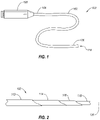
- FIG. 1 illustrates a schematic representation of an intravascular device delivery system 100.
- the system 100 may include an elongated member 102 having a proximal end 104 and a distal end 106.
- a handle 108 may be connected to the proximal end 104 of the elongated member 102.
- An intravascular device 110 may be positioned at and/or connected to the distal end 106.
- the elongated member 102 may be flexible, allowing the elongated member 102 to traverse a patient's tortuous vasculature or other anatomy.
- the elongated member 102 may deliver the intravascular device 110 to a target location in the patient's body, such as delivering a filter, scaffold, stent, body tissue repair device, heart valve, or other implantable devices.
- the system 100 and elongated member 102 may be provided without an intravascular device 110 at the distal end 106 such that the system may recapture, reposition, or otherwise move an intravascular device previously positioned in the patient's body.
- the elongated member 102 of the system 100 may include one or more elements therein.
- An element of the elongated member 102 may include a catheter, a guidewire, a sheath, a drive cable, other tubular and/or solid element, or combinations thereof.
- an element of the elongated member 102 may extend an entire length of the elongated member 102 from a proximal end 104 to a distal end 106 of the elongated member 102.
- an element of the elongated member 102 may have a length less than the entire length of the elongated member 102.
- an element may provide support to the elongated member 102 from the proximal end 104 toward the distal end 106 without continuing the entire length to the distal end 106.
- FIG. 2 is a side partial cutaway view of the elongated member 102 of the intravascular device delivery system 100 of FIG. 1 .
- the elongated member 102 may include an outer sleeve 112, a flexible hypotube 114, a steerable catheter 116, and an inner catheter 118.
- the inner element may be an inner catheter.
- the inner element 118 may be a guidewire or other guide element to assist in directing the elongated member 102 through tortuous anatomy.
- the flexible hypotube may be a lasercut hypotube, a hydrocut hypotube, a hypotube with one or more cuts therein by other cutting methods, such as EDM or mechanical cutting, or a 3D printed hypotube with one or more openings therein.
- the elongated member 102 has a longitudinal axis 126 that extends from the proximal end (i.e., proximal end 104 in FIG. 1 ) to the distal end (i.e., distal end 106 in FIG. 1 ) of the elongated member 102.
- all of the elements of the elongated member 102 may extend a full length of the elongated member 102.
- at least one of the elements may have a length that is less than the full length of the elongated member 102.
- the flexible hypotube 114 may have a length that is less than the full length of the elongated member 102.
- the outer sleeve 112 may have a length less than the full length of the elongated member 102.
- the flexible hypotube 114 may have a length that is less than a length of the steerable catheter 116.
- the flexible hypotube 114 may have a wall thickness that is less than the thickness of a conventional steerable catheter.
- the flexible hypotube 114 may have a wall thickness that is a percentage of a wall thickness of the steerable catheter 116 in a range having upper value, a lower value, or upper and lower values including any of 10%, 15%, 20%, 25%, 30%, 35%, 40%, 45%, 50%, 60%, 70%), 80%), 90% or any values therebetween.
- the wall thickness of the flexible hypotube 114 may be less than 90% of the wall thickness of the steerable catheter 116.
- the wall thickness of the flexible hypotube 114 may be between 10%) and 90% of the wall thickness of the steerable catheter 116.
- the wall thickness of the flexible hypotube 114 may be between 15%> and 50% of the wall thickness of the steerable catheter 116. In at least one arrangement, the wall thickness of the flexible hypotube 114 may be about 20% of the wall thickness of the steerable catheter 116.
- FIG. 3 illustrates an example of a series of compound bends that the elongated member 102 may perform during the delivery, repair, recapture, repositioning, or other interaction with an intravascular device at a mitral valve in a patient's heart. While arrangements are described herein in relation to an intravascular device and intravascular device delivery system for mitral valve repair, it should be understood that arrangements in accordance with the present disclosure may be used in other intravascular procedures, such as septal repair, transapical procedures, transeptal procedures, transarterial procedures, other coronary procedures, other intravascular procedures, or other intraluminal medical procedures.
- the elongated member 102 may be steered by the steerable catheter 116.
- the steerable catheter 116 may be any suitable steerable catheter 116 known in the art.
- the steerable catheter 116 may be steerable in at least one plane of motion.
- the steerable catheter 116 may be steerable in at least two planes of motion.
- the steerable catheter 116 is steerable in two planes of motion substantially perpendicular to one another.
- the elongated member 102 is shown with only the flexible hypotube 114 and the steerable catheter 116 for clarity.
- the steerable catheter 116 may extend distally at least partially from a distal end of the flexible hypotube 114.
- the elongated member 102 has a first bend 120 in which both the flexible hypotube 114 and the steerable catheter 116 deflect.
- the first bend 120 may have a first bend angle 124 measured between a first longitudinal axis 126-1 proximal of the first bend 120 to a second longitudinal axis 126-2 distal the first bend 120.
- the first bend angle 124 may be in a range having an upper value, a lower value, or an upper and lower value including any of 60°, 65°, 70°, 75°, 80°, 85°, 90°, 95°, 100°, 105°, 110°, 115°, 120°, 125°, 130°, 135°, 140°, 145°, 150°, 155°, 160°, 165°, 170°, 175°, or any values therebetween.
- the first bend angle 124 may be greater than 60°.
- the first bend angle 124 may be less than 175°.
- the first bend angle 124 may be in a range of 60° to 175°.
- the first bend angle 124 may be in a range of 90° to 120°. In at least one example, the first bend angle 124 may be about 105°.
- the elongated member 102 has a second bend 128 in which the steerable catheter 116 is deflected with a compound angle relative to the first longitudinal axis 126-1.
- the second bend 128 has a second bend angle 130 between a third longitudinal axis 126-3 distal of the second bend 128 relative to the second longitudinal axis 126-2 proximal the second bend 128.
- the second bend 128 may also have a rotational angle 132 relative to a plane in which the first longitudinal axis 126-1 and the second longitudinal axis 126-2 lie. In other words, the rotational angle 132 is relative to the amount of rotation of the third longitudinal axis 126-3 relative to the direction of the first bend 120.
- the second bend angle 130 may be in a range having an upper value, a lower value, or an upper and lower value including any of 60°, 65°, 70°, 75°, 80°, 85°, 90°, 95°, 100°, 105°, 110°, 115°, 120°, 125°, 130°, 135°, 140°, 145°, 150°, 155°, 160°, 165°, 170°, 175°, or any values therebetween.
- the second bend angle 130 may be greater than 60°.
- the second bend angle 130 may be less than 175°.
- the second bend angle 130 may be in a range of 60° to 175°.
- the second bend angle 130 may be in a range of 80° to 110°. In at least one example, the second bend angle 130 may be about 90°.
- the rotational angle 132 of the third longitudinal axis 126-3 (i.e., a distal end of the steerable catheter 116) relative to the first longitudinal axis 126-1 may be in a range having an upper value, a lower value, or an upper and lower value including any of 30°, 35°, 40°, 45°, 50°, 55°, 60°, 65°, 70°, 75°, 80°, 85°, 90°, 100°, 110°, 120°, 130°, 140°, 150°, 160°, or any values therebetween.
- the rotational angle 132 may be greater than 30°. In other example, the rotational angle 132 may be less than 160°.
- the rotational angle 132 may be in a range of 30° to 160°. In further examples, the rotational angle 132 may be in a range of 45° to 135°. In at least one example, the second bend angle 130 may be about 60°.
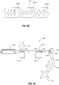
- FIG. 4A illustrates a flat view of a cut pattern for a flexible hypotube 114.
- the flat view illustrates the pattern of the cuts as though a cylindrical hypotube were laid flat.
- the top edge of the cut pattern and the bottom edge of the cut pattern are connected and continuous in the flexible hypotube 114 such that the slits 134 and island cuts 136 are oriented circumferential and spaced apart by the spines therebetween.
- the cut pattern may include at least one slit 134 and at least one island cut 136.
- the cut pattern may have a plurality of slits 134 and/or a plurality of island cuts 136.
- the slit 134 may transmit longitudinal force along the flexible hypotube 114 and allow expansion of the flexible hypotube 114 when the flexible hypotube 114 is deflected in a direction opposite the slit 134.
- the island cuts 136 may allow compression of the flexible hypotube 114 when the flexible hypotube 114 is deflected in a direction of the island cuts 136.
- slits 134 and island cuts 136 located rotationally opposite one another on a flexible hypotube 114 may direct preferential bending of the hypotube along a center line 138 of the island cuts 136.
- a flexible hypotube 114 with the cut pattern of FIG. 4A may preferentially bend along the center line 138 within a bend region defined by the cut pattern.
- island cuts 136 are depicted in FIG. 4A as diamond-shaped, the island cuts 136 may have one or more other shapes, such as square, rhombohedral, triangular, rectangular, circular, oblong, other elliptical, other polygonal, irregular, or combinations thereof.
- FIG. 4B is a side view of a flexible hypotube 214 having a plurality of island cuts 236 therein which may vary in size along a longitudinal length of the flexible hypotube 214.
- a first island cut 236-1 may be shorter in the longitudinal direction than a second island cut 236-2 in a different longitudinal portion of the flexible hypotube 214.
- the island cuts increase in longitudinal length in a distal direction.
- a third island cut 236-3 may be narrower in the rotational direction about the flexible hypotube 214 than the second island cut 236-2 in a different longitudinal portion of the flexible hypotube 214.
- the island cuts become wider in the rotation direction in a distal direction.
- the flexible hypotube 214 may have one or more slits opposite the island cuts 236 (not visible in FIG. 4B ).
- FIG. 5A illustrates the preferential bending of the flexible hypotube 114 in the intravascular device delivery system 100. Only the flexible hypotube 114 and steerable catheter 116 of the elongated member are shown in FIG. 5 for clarity and to show the relative motion of the flexible hypotube 114 and steerable catheter 116.
- the flexible hypotube 114 has a bend region 146 containing one or more slits 134 and island cuts 136.
- the steerable catheter 116 may apply a transverse force to the flexible hypotube 114 to bend the bend region 146.
- the slits 134 may open (i.e., expand) and the island cuts 136 may close (i.e., compress) to allow the bend region 146 to bend at the first bend 120.
- the orientation of the first bend 120 i.e. rotational orientation about a longitudinal axis
- the flexible hypotube 114 and steerable catheter 116 may be rotationally fixed relative to one another in one or more key assemblies.
- the flexible hypotube 114 and steerable catheter 116 are rotationally fixed relative to one another by a first key assembly 140 and a second key assembly 142.
- the flexible hypotube 114 and the steerable catheter 116 may be rotationally fixed relative to one another by one key assembly.
- the flexible hypotube 114 and the steerable catheter 116 may be rotationally fixed relative to one another by three or more key assemblies positioned longitudinally along the flexible hypotube 114 and the steerable catheter 116.
- the flexible hypotube 114 and steerable catheter 116 may be rotationally fixed relative to one another by a first key assembly 140 that extends an entire longitudinal length of the flexible hypotube 114 or steerable catheter 116.
- the first key assembly 140 may rotationally fix the flexible hypotube 114 and the steerable catheter 116 by a mechanical interlock of one or more elements between the flexible hypotube 114 and the steerable catheter 116.
- the flexible hypotube 114 includes a first slot 148 and a second slot 150.
- the first slot 148 and the second slot 150 are configured to receive a first tab 152 and a second tab 154 of the steerable catheter 116, such that the first tab 152 engages with the first slot 148 to form the first key assembly 140 and the second tab 154 engages with the second slot 150 to form the second key assembly 142.
- the mechanical interlock may have other forms.
- the first slot 148 may be located in the steerable catheter 116 and the first tab 152 may be fixed relative to the flexible hypotube.
- the first slot 148 may extend substantially or the entire longitudinal length of the flexible hypotube 114 or steerable catheter 116 and a plurality of tabs (e.g., first tab 152 and second tab 154) may engage with the first slot 148.
- first tab 152 and second tab 154 may be integrally formed with the steerable catheter 116.
- an integrally formed first tab 152 and/or second tab 154 may introduce challenges during assembly of the device.
- a first tab 152 and/or second tab 154 may be connected to the steerable catheter 116 through the first slot 148 and/or second slot 150, respectively, after the steerable catheter 116 is positioned radially within the flexible hypotube 114.
- first tab 152 and/or second tab 154 may be connected to an outer surface of the steerable catheter 116 by sonic welding, thermal welding, an adhesive, a clip, a pin, a rivet, a screw, another mechanical fastener, or a combination thereof.
- FIG. 5B is a longitudinal cross-sectional of a steerable catheter 216 with a tab 252 in accordance with the invention.
- the steerable catheter 216 has a body 253.
- the body 253 includes a lumen 255 contained within a wall of the body 253 that extends along a least a portion of the longitudinal length of the steerable catheter 216.
- One or more cuts 257 are made in the outer surface of the body 253 through to the lumen 255.
- a tab 252 is inserted into the one or more cuts 257 to retain the tab 252 in the body 253 of the steerable catheter 216 with at least a portion of the tab 252 extending radially from the body 253, as shown in FIG. 5B .
- the tab 252 may include or be made of spring steel, shape memory material like Nitinol, other steel alloys, aluminum, titanium, an organic polymer, an inorganic polymer, other materials, or combinations thereof. In some arrangements, the tab 252 is held in the lumen 255 with an adhesive.
- the tab 252 is placed in the steerable catheter 216 before positioning the steerable catheter 216 in the flexible hypotube.
- the tab 252 is held in the lumen 255 with an adhesive at only one end of the tab 252, allowing the other end to move freely. The free end allows the tab to collapse radially during positioning of the steerable catheter 216 in the flexible hypotube.
- the tab 352 may have other shapes than shown in FIG. 5B .
- the tab 352 may have discontinuous corners, such as 90° corners.
- the tab 352 may have a mix of curved surfaces and discontinuous corners to facilitate assembly of the tab 352 into the body 353 of the steerable catheter 316 through the slot 350 of the flexible hypotube 314 while allowing for 1:1 torque transmission between the steerable catheter 316 and the flexible hypotube 314.
- the first key assembly 140 rotationally keys the flexible hypotube to the steerable catheter 116 by limiting and/or preventing movement of the first tab 152 rotationally relative to the first slot 148.
- the second key assembly 142 rotationally keys the flexible hypotube 114 to the steerable catheter 116 at a location distal of the first key assembly 140 by limiting and/or preventing movement of the second tab 154 rotationally relative to the second slot 150.
- the first slot 148 has a first slot length 156 in a longitudinal direction.
- the first tab 152 may move longitudinally within the first slot 148, allowing at least a portion of the steerable catheter 116 to translate longitudinally relative to the flexible hypotube 114 while the steerable catheter 116 is rotationally keyed to the flexible hypotube 114.
- the second tab 154 may move longitudinally within the second slot 150, allowing at least another portion of the steerable catheter 116 (distal of the first key assembly 140) to translate longitudinally relative to the flexible hypotube 114.
- Longitudinal translation of the steerable catheter 116 relative to the flexible hypotube 114 allows the steerable catheter 116 to bend the bend region 146 of the flexible hypotube 114 at the first bend 120, and then translate longitudinally in a distal direction and project from the flexible hypotube 114 (i.e., extend beyond a distal end of the flexible hypotube 114).
- the steerable catheter 116 may bend the flexible hypotube 114 at the bend region 146 in a first direction and move distally through the flexible hypotube 114 beyond the distal end of the flexible hypotube 114.
- the steerable catheter 116 may then be steered in a second direction by one or more controls on the handle 108.
- the amount of longitudinally displacement of the steerable catheter 116 relative to the flexible hypotube 114 may be at least partially determined by the first slot length 156 and/or the second slot length 158.
- the first slot length 156 may be equivalent to the second slot length 158. In other arrangements, the first slot length 156 may be greater than the second slot length 158. In yet other arrangements, the first slot length 156 may be less than the second slot length 158.
- the first slot length 156 and/or the second slot length 158 may be in a range including an upper value, a lower value, or upper and lower values including any of 2.0 centimeters, 2.5 centimeters, 3.0 centimeters, 3.5 centimeters, 4.0 centimeters, 4.5 centimeters, 5.0 centimeters, 5.5 centimeters, 6.0 centimeters, 6.5 centimeters, 7.0 centimeters, 7.5 centimeters, 8.0 centimeters, 8.5 centimeters, 9.0 centimeters, 9.5 centimeters, 10.0 centimeters, or any values therebetween.
- first slot length 156 and/or the second slot length 158 may be greater than 2.0 centimeters. In another example, the first slot length 156 and/or the second slot length 158 may be less than 10.0 centimeters. In yet other examples, the first slot length 156 and/or the second slot length 158 may be between 2.0 centimeters and 5.0 centimeters. In further examples, the first slot length 156 and/or the second slot length 158 may be in a range of 2.5 centimeters to 4.5 centimeters. In at least one arrangement, the first slot length 156 and/or the second slot length 158 may be about 3.0 centimeters.
- the first slot 148 and the second slot 150 are rotationally aligned with one another in the arrangement of FIG. 5A .
- the first slot 148 and second slot 150 may be rotationally displaced from one another.
- the first slot 148 may be on a first side of the flexible hypotube 114 and the second slot 150 may be displaced at an angular amount from the first slot 148, such as 180° to angularly oppose the first slot 148.
- the first slot 148 and second slot 150 may be rotationally displaced from one another by another angle between 0° and 180°.
- the first slot length 156 and/or second slot length 158 may limit the amount the steerable catheter 116 may extend distally of a distal end of the flexible hypotube 114.
- the amount the steerable catheter 116 may extend distally of a distal end of the flexible hypotube 114 may be in a range including an upper value, a lower value, or upper and lower values including any of 2.0 centimeters, 2.5 centimeters, 3.0 centimeters, 3.5 centimeters, 4.0 centimeters, 4.5 centimeters, 5.0 centimeters, 5.5 centimeters, 6.0 centimeters, 6.5 centimeters, 7.0 centimeters, 7.5 centimeters, 8.0 centimeters, 8.5 centimeters, 9.0 centimeters, 9.5 centimeters, 10.0 centimeters or any values therebetween.
- the amount the steerable catheter 116 may extend distally of a distal end of the flexible hypotube 114 may be greater than 2.0 centimeters. In another example, the amount the steerable catheter 116 may extend distally of a distal end of the flexible hypotube 114 may be less than 10.0 centimeters. In yet other examples, the amount the steerable catheter 116 may extend distally of a distal end of the flexible hypotube 114 may be between 2.0 centimeters and 10.0 centimeters. In further examples, the amount the steerable catheter 116 may extend distally of a distal end of the flexible hypotube 114 may be in a range of 2.5 centimeters to 6.5 centimeters. In at least one arrangement, the amount the steerable catheter 116 may extend distally of a distal end of the flexible hypotube 114 may be about 3.0 centimeters.
- the steerable catheter 116 may be steered about the second bend 128, as described in relation to FIG. 3 , and an intravascular device 110 may be deployed distally from the steerable catheter 116.
- the intravascular device 110 may be deployed by activating one or more portions of the intravascular device 110 (such as wings, clips, extensions, needles, etc.).
- the intravascular device 110 may be deployed by moving the intravascular device 110 longitudinally relative to a sleeve or sheath constraining a radial expansion of the intravascular device 110 (such as with a self-expanding stent or other self-expanding intravascular device 110).
- FIG. 6 illustrates a method 260 for delivering an intravascular device.
- the method 260 includes steering 262 a portion of an elongated member.
- steering 262 the portion of the elongated member may include using a steerable catheter to steer a distal end of the elongated member.
- steering 262 the portion of the elongated member may include steering the portion of the elongated member in a bodily cavity.
- the steering 262 may be performed using one or more cables, wires, sutures, or other force transmission mechanisms to transmit force from a handle to the portion of the elongated member to be deflected.
- the elongated member may have one steerable catheter.
- the elongated member may have a plurality of steerable catheters.
- the elongated member may have a steerable catheter that is steerable in at least two planes.
- the elongated member may have a first steerable catheter that is steerable in a first plane and a second steerable catheter that is steerable in a second plane.
- the method 260 includes bending 264 a bend region of a flexible hypotube.
- the flexible hypotube may preferentially bend in plane.
- the flexible hypotube may preferentially bend in a particular direction within a plane, relative to a longitudinal axis of the elongated member.
- the flexible hypotube may have a plurality of cuts, such as island cuts and/or slits, in the body of the flexible hypotube to direct bending of the flexible hypotube.
- the method 260 includes advancing 266 at least a portion of the steerable catheter (or catheters) in a distal direction.
- the steerable catheter may follow the bend of the flexible hypotube and a steerable portion of the steerable catheter may be positioned distally beyond a distal end of the flexible hypotube.
- the method 260 includes steering 268 a portion of the steerable catheter advanced distally beyond the flexible hypotube.
- steering the portion of the steerable catheter that is advanced distally beyond the flexible hypotube includes steering the steerable catheter in a second plane that is non-coplanar from the first plane in which the flexible hypotube bends. For example, steering 268 the steerable catheter after advancing 266 the steerable catheter allows for the compound bend shown in FIG. 3 .
- the method 260 further includes positioning the distal end of the steerable catheter at or adjacent to a target location.
- the target location may be a delivery location for an intravascular device.
- the target location may be a repositioning location for a partially deployed intravascular device.
- the target location may be an opening to be close by an intravascular device.
- an intravascular device delivery system may include a flexible hypotube 314 that is embedded in a catheter body 370.
- the catheter body 370 includes at least one lumen 372 through which a tension or steering cable 374 is connected to an end ring 376 welded to the flexible hypotube 314.
- the proximal ends of the tension cable 374 are attached to a handle to allow the flexible hypotube 314 to deflect when tension force is applied to the tension cable 374.
- the intravascular device delivery system herein described may allow delivery of larger intravascular devices and/or through smaller bodily conduits.
- the intravascular device delivery system may allow for new and/or improved procedures with less risk to the patient and greater ease of operation to the medical professional.
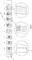
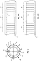
- FIG. 8 there is illustrated a flat view of another cut pattern for a flexible hypotube or catheter.
- the flat view illustrates the pattern of the cuts as though a cylindrical hypotube, for example, were laid flat.
- the top edge of the cut pattern and the bottom edge of the cut pattern are connected and continuous in the flexible hypotube, such that the slits and island cuts are oriented circumferential and spaced apart by the spines therebetween.
- This particular cut pattern allows the flexible hypotube to bend in 2 different planes, while providing desired 1:1 torque control and flexibility. Those planes can be at various angular orientations relative to each other, such as perpendicular or non-perpendicular planes.
- a location of the spine and the design of the slits and cuts define how the hypotube deflects during steering of the intravascular device delivery system.
- the flexible area of the flexible hypotube i.e., those areas with the slits and/or cuts, can have various lengths and the slits and cuts of FIGS. 8 and 9 can be the same as other slits and cuts described herein.
- one hypotube 400 can include various sections with and without flexibility patterns or cut patterns based upon the particular movement from the hypotube 400.
- sections I-X are stiffer than other sections to aid with steering the intravascular device delivery system.
- section I includes a number of holes 402, however, a remainder of that section has no cuts or slits.
- the holes 402 can have a diameter of about 0.5mm and there can be about 9 holes disposed about the circumference of Section I. Other diameters and number of holes are also possible.
- the diameter of the holes 402 can be from about 0.3mm to about 1mm.
- the number of holes can be greater than or less than 9.
- the number of holes can be about 3 to about 12.
- Sections II-IX have differing numbers of slits and/or cuts, while section X has no cuts or slits.
- the cuts and islands can vary based upon the selected flexibility and torque of the hypotube 400.
- Section II has 12 cut rings, each ring having a width of about 5.5mm
- Section III is similar to section II, but rotated 90 degrees, and with 6 rings, each having a width of about 2.5mm
- Section IV has 12 rings, each having a width of about 5.5 mm
- Section V has 14 rings, each having a width of about 13mm
- Section VI is similar to section II, but rotated 90 degrees
- Section VII has 30 cut rings, each ring having a width of about 14.5mm
- Section VIII is similar to Section IV, but rotated 90 degrees
- Section VIII is similar to Section IV, but rotated 90 degrees, with 12 cut rings, each ring having a width of about 5.5mm
- Section IX is similar to Section V with 11 cut rings, each ring having a width of about 10mm
- the number of rings can be from about 1 to about 40, with a width of the rings ranging from about 0.5mm to about 7mm.
- the hypotube 400 can be fabricated from a single material, such as stainless steel or shape memory material, such as Nitinol
- the hypotube 400 can include a combination of materials.
- the deformation in Section II-X may exceed the plastic deformation ability of a stainless steel.
- a material much better suited for these Sections II-X could be a shape memory material, such as Nitinol with a plastic deformation limit of about 8% compared to that of stainless steel of ⁇ 1%. Therefore, in one configuration, different areas or regions of the hypotube 400 can be formed from a material with high deformation limits, such as but not limited to, Nitinol or some other superelastic, pseudoelastic, or shape memory material.
- those sections where high deformation occurs could be formed from Nitinol, while a remainder of the hypotube can be formed from a less expensive material.
- the less expensive material could be stainless steel 304 or 316. Since these materials are dissimilar, a mechanical interlock in a low stress area can be used to join the two different stiffness sections or portions.
- a mechanical interlock 410 can be used, one example of a mechanical interlock 410 being illustrated in FIG. 9 .
- the mechanical interlock 410 and associated portions of the hypotube are illustrated in a flat view.
- the flat view illustrates the pattern of the mechanical interlock 410 as though a cylindrical hypotube were laid flat.
- the top edge of the mechanical interlock 410 and the bottom edge of the mechanical interlock 410 are connected and continuous in the flexible hypotube.
- Section IX and X from FIG. 8 are illustrated in FIG. 9 , with Section IX having a different configuration of rings, and the overall length of that section being about 340mm.
- the mechanical interlock 410 includes a male portion 412 and a female portion 414.
- the male portion 412 has at least one finger 420, with an enlarged member 422 disposed at an end thereof.
- the female portion 414 is complementary to the male portion 412 and includes at least one channel 424 with a receiving space 426 at its end to accommodate the enlarged member 422.
- the two portions of the hypotube 400 connect together when the finger 420 and enlarged member 422 are received in the channel 424 and receiving space 426.
- the finger 420 and the enlarged member 422 can be flexible enough to snap into the channel 424 and receiving space 426 having a matching shape.
- the above-described mechanical interlock 400 is not limited to this specific mechanical interlock described and other mechanical locks can be used as well.
- the enlarged member 422 can be a ball or have an elongate form, whether or not curved, square, rhombohedral, triangular, rectangular, circular, oblong, other elliptical, other polygonal, irregular, or combinations thereof.
- the receiving space 426 can accommodate the ball or other elongate form while being complementary to the enlarged member 422.
- the finger 420 and channel 424 can also have various configurations and orientations.
- the hypotube 400 can be covered with an outer member 430, such one or more braids, outer sheaths or other structures to aid in retaining the finger 420 and the enlarged member 422 in the channel 424 and the receiving space 426, respectively.
- an outer member 430 such one or more braids, outer sheaths or other structures to aid in retaining the finger 420 and the enlarged member 422 in the channel 424 and the receiving space 426, respectively.
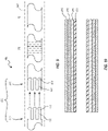
- the function of the flexible hypotube and the steerable catheter can be combined into a catheter having a single hypotube with channels for tension cables used to deflect the catheter.
- the hypotube 400 such as the combined Nitinol/Stainless steel laser cut hypotube described in relation to FIGS. 8-9 (or another hypotube fabricated from another metal, alloy, or other material), can be covered with tubes 440 to create a space for the tension cable (not shown) responsible for the deflection of the catheter.
- tubes 440 could be made of polyamide or some other polymer, and could optionally include a polytetrafluoroethylene (PTFE) liner.
- PTFE polytetrafluoroethylene
- sacrificial mandrels which can be removed after forming the catheter, can be placed on an exterior surface of the hypotube 400, with the tubes 440 or mandrels being placed along the axis of the connected hypotubes 400, i.e., a hypotube of a stiffer material and a hypotube of a less stiff material.
- Covering the tubes 440 or mandrels can be a braid or coil 442, which helps position the tubes 440 or mandrels and keep them in place when an outer sheath 444, such as a polymeric jacket, is applied to the braid 442 and the tubes 442.
- the braid or coil 442 limits movement of the tension cable (not shown), i.e., bowing of the tension cable, when high-tension forces are applied during bending and movement of the catheter.
- the outer sheath 444 can be an extrusion that is placed over the hypotube 400, the tubes 440, and the braid or coil 442. This extrusion is subsequently covered by a heat shrink tubing, with the extrusion reflowing and connected to the hypotube 400, the tubes 440, and the braid or coil 442. In areas of deflection, a softer outer sheath 444 is provided. The lower durometer of the polymer formed at the deflection areas allows for easier deflection when a pulling force is applied to the tension cable (not shown). Optionally, a hydrophilic coating can be applied to the outer sheath 444.
- the outer sheath 444 can be a Polyether block amide (PEBAX) or other polymer, with a distal flexible portion of the outer sheath 444, and so the intravascular device delivery system.
- PEBAX Polyether block amide
- the braid 442 and/or outer sheath 444 whether individually or collectively, aid with keeping the mechanical interlock 410 aligned for desired torque transmission, as well as a certain amount of pull or push force. In other configurations, only one of the braid 442 and outer sheath 444 can be included in the hypotube 400.
- the intravascular device delivery system includes a distal portion with selectable stiffness to aid with steering and positioning the flexible elongated member, such as an elongated member similar to the elongated member 102 in FIG. 1 .
- Selectable stiffness aids, for instance, in positioning an intravascular device within a particular anatomical structure or traversing the tortuous anatomy.
- the selectably stiffened catheter can have a variable stiffness length between a first curve adjacent the septum, for instance, and a second curve the catheter makes to turn towards another anatomical structure within the heart, such as the mitral annulus.
- FIGS. 11 and 12 illustrate a portion of an intravascular device delivery system 500 having a catheter body 570 with at least one lumen 572 through which a tension or steering cable (not shown) is connected or loops around a portion of an end ring (not shown) attached to a flexible hypotube 514, similar to that illustrated in FIG. 7 .
- the structure of the catheter body 570 is similar to the structure of catheter body 370 described herein and so the description of catheter body 370 is applicable to the catheter body 570.
- the proximal ends of the tension cable are attached to a handle, such as handle 108 ( FIG. 1 ), to allow the flexible hypotube 514 to deflect when tension force is applied to the tension cable extending through the at least one lumen 572 formed from tubes supported by the hypotube 514, similar to tubes 440, or from sacrificial mandrels that have been removed from the catheter during manufacture.
- the at least one lumen 572 is illustrated as being positioned at each bending axis BA 1 and BA 2 of the catheter body 570, with a lumen on opposite sides of the bending axis BA 1 and BA 2 . While two bending axes BA 1 and BA 2 are illustrated, it would be understood that a greater or lesser number of bending axes could be provided.
- the catheter body 570 includes a first region 580 and a second region 582, each with enhanced flexibility because of, respectively, a flexibility pattern 584 and 586.
- a flexibility pattern 584 and 586 provides different degrees of stiffness to those particular regions 580 and 582 compared with a third region 588 that is formed either without any cut pattern, as illustrated in FIG. 11 , or with a flexibility pattern that results in a stiffer area than the first region 580 or the second region 582.
- the flexibility pattern 584 and 586 can be those illustrated and described in FIGS. 4A , 4B , 8 , and 9 , or other patterns of cuts, islands, and other structures that provide different stiffness to the catheter body 570.
- the flexibility pattern 584 and 586 precisely define bending locations and directions, such as allowing the catheter body 570 to bend in two different planes that are perpendicular or transverse to each other, while also defining a distance between the first region 580 and the second region 582, i.e., a length of the third region 588 that can range from about 0cm to about 5cm.
- the lumens or channels 590 can be formed from tubes 540 disposed on an exterior of the hypotube 514 or by sacrificial mandrels, which can be removed after forming the catheter body 570.
- Those tubes 540 like the tubes 440 in FIG. 10 , are covered with a braid or coil 542 and optional an outer sheath 544 in a similar manner to the catheter body 370.
- FIG. 12 illustrates the outer sheath 544 reflown and connected to the hypotube 514, the tubes 540, and the braid or coil 542.
- the stiffening members 592 are elongated and movable within the lumens 590. In one position, illustrated in FIG. 13A , the stiffening members 592 at least partly overlap with the flexibility pattern 586, while in another position the stiffening members 592 are retracted from and separated from the flexibility pattern 586, as illustrated in FIG. 13B . When overlapping the flexibility pattern 586, the stiffness of stiffening member 592 limits bending at the second region 582. To limit bending, an elongate shaft member 594 of the stiffening member 592 has a stiffness greater than the stiffness of the second region 582.
- the elongate shaft member 594 can be fabricated from a hardened metal or alloy, such as steel, or any other stiff material, such as fiber reinforced polymers, ceramics, glass organic or inorganic materials, or composites.
- the stiffening members 592 are withdrawn from alignment with the flexibility pattern 586 and they will be uncovered.
- the second region 584 can then bend or deflect when force is applied to the tension or steering cables 574.
- the actuating member 596 is advanced distally within the lumen 590, the elongate shaft member 594 again overlaps with the flexibility pattern 586 and the stiffness of the second region 582 is increased.
- the actuating member 596 can include a flexible pull member 598, such as a pull cable, flexible rod, etc, and a compression member 600 disposed around the flexible pull member 598.
- the flexible pull member 598 has sufficient strength in tension to move the elongate shaft member 594 proximally, while the compression member 600, such as a compression coil, flexible metallic or polymeric tube, or other structure, which provides sufficient rigidity or column strength to transfer a force applied to the elongate shaft member 594 in a distal direction to advance the elongate shaft member 594 within the lumen 590.
- a stated value should therefore be interpreted broadly enough to encompass values that are at least close enough to the stated value to perform a desired function or achieve a desired result.
- the stated values include at least the variation to be expected in a suitable manufacturing or production process, and may include values that are within 5%, within 1%, within 0.1%, or within 0.01% of a stated value.
Claims (15)
- Système de distribution de dispositif intravasculaire (100), le système (100) comprenant :un élément allongé (102), l'élément allongé (102) incluant :un cathéter orientable (116, 216, 316) présentant une extrémité proximale, une extrémité distale, et un axe longitudinal (126) s'étendant entre celles-ci ; etun hypotube flexible (114, 214, 314) positionné radialement à l'extérieur et circonférentiellement autour du cathéter orientable (116, 216, 316) et coaxial avec le cathéter orientable (116, 216, 316), l'hypotube flexible (114, 214, 314) incluant au moins une découpe d'îlot (136) et au moins une découpe de fente (134) pour diriger la flexibilité de l'hypotube flexible (114, 214, 314),dans lequel l'hypotube flexible (114, 214, 314) et le cathéter orientable (116, 216, 316) sont fixés de manière rotative l'un à l'autre au niveau d'un premier ensemble à clavette (140), une première languette (152, 252, 352) venant en prise avec une première fente (148) pour former le premier ensemble à clavette (140), et la première fente (148) présentant une première longueur de fente (156) configurée pour déterminer au moins partiellement une quantité de déplacement longitudinal du cathéter orientable (116, 216, 316) par rapport à l'hypotube flexible (114, 214, 314) lorsque le cathéter orientable (116, 216, 316) s'étend distalement au-delà d'une extrémité distale de l'hypotube flexible (114, 214, 314) lorsque la première languette (152, 252, 352) se déplace longitudinalement à l'intérieur de la première fente (148), caractérisé en ce quele cathéter orientable (116, 216, 316) présente un corps (253, 353), le corps (253, 353) incluant une lumière (255, 355) contenue à l'intérieur d'une paroi du corps (253, 353) qui s'étend le long d'au moins une partie d'une longueur longitudinale du cathéter orientable (116, 216, 316), et une ou plusieurs découpes (257) réalisées dans une surface extérieure du corps (253, 353) à travers la lumière (255, 355),la première languette (152, 252, 352) étant insérée dans les une ou plusieurs découpes (257), et les découpes (257) étant configurées pour retenir la première languette (152, 252, 352) dans le corps (253, 353) du cathéter orientable (116, 216, 316), au moins une partie de la première languette (152, 252, 352) s'étendant radialement à partir du corps (253, 353).
- Système (100) selon la revendication 1, dans lequel l'hypotube flexible (114, 214, 314) et le cathéter orientable (116, 216, 316) sont fixés de manière rotative au niveau d'un second ensemble à clavette (142) distal du premier ensemble à clavette (140).
- Système (100) selon la revendication 1, dans lequel l'hypotube flexible (114, 214, 314) présente la au moins une découpe de fente (134) et au moins une découpe d'îlot (136) dans une région coudée (146) pour diriger préférentiellement la flexibilité de l'hypotube flexible (114, 214, 314) dans une direction au niveau de la région coudée (146).
- Système (100) selon la revendication 3, dans lequel l'hypotube flexible (114, 214, 314) et le cathéter orientable (116, 216, 316) sont fixés de manière rotative au niveau d'un second ensemble à clavette (142) distal du premier ensemble à clavette (140) et proximal à la région coudée (146).
- Système (100) selon la revendication 1, dans lequel le cathéter orientable (116, 216, 316) est orientable dans au moins deux plans.
- Système (100) selon la revendication 1, dans lequel l'hypotube flexible (114, 214, 314) comprend en outre une pluralité d'épines angulairement opposées entre ladite au moins une découpe de fente (134) et ladite au moins une découpe d'îlot (136), les épines étant angulairement opposées les unes aux autres.
- Système selon la revendication 1, dans lequel l'hypotube flexible comprend un verrouillage mécanique (410).
- Système (100) selon la revendication 7, dans lequel le verrouillage mécanique (410) comprend au moins un doigt (420) reçu dans au moins un canal (424), le au moins un doigt (420) étant formé dans une première partie d'hypotube (412) et le au moins un canal (424) étant formé dans une seconde partie d'hypotube (414), la première partie d'hypotube (412) et la seconde partie d'hypotube (414) présentant des rigidités différentes.
- Système selon la revendication 1, comprenant en outre un élément de raidissement (592) disposé à l'intérieur d'une lumière (590) de l'élément allongé.
- Système selon la revendication 9, dans lequel la au moins une découpe d'îlot et au moins une découpe de fente forment un motif de flexibilité (584, 586) et l'élément raidisseur (592) est disposé de manière coulissante à l'intérieur de la lumière (590) entre une première position chevauchant au moins partiellement le motif de flexibilité (584, 586) et une seconde position espacée du motif de flexibilité (584, 586).
- Système (100) selon la revendication 5, comprenant en outre :
une poignée (108) présentant une ou plusieurs commandes sur celle-ci, l'élément allongé (102) étant couplé de manière fonctionnelle à la poignée (108), et l'hypotube flexible (114, 214, 314) et le cathéter orientable (116, 216, 316) étant fixés de manière rotative l'un à l'autre au niveau du premier ensemble à clavette (140) au niveau d'une extrémité proximale de l'hypotube flexible (114, 214, 314), au moins une parmi les une ou plusieurs commandes étant configurée pour déplacer le cathéter orientable (116, 216, 316) longitudinalement par rapport à l'hypotube flexible (114, 214, 314). - Système (100) selon la revendication 11, dans lequel la première fente (148) est dans l'hypotube flexible (114, 214, 314) et la première languette (152, 252, 352) est fixée au cathéter orientable (116, 216, 316) et positionnée au moins partiellement dans la première fente (148).
- Système (100) selon la revendication 12, dans lequel la première longueur de fente se situe dans une plage allant de 2,0 centimètres à 7,0 centimètres.
- Système (100) selon la revendication 2, dans lequel le second ensemble à clavette (142) présente une seconde fente (150) dans l'hypotube flexible (114, 214, 314) et une seconde languette (154) fixée au cathéter orientable (116, 216, 316) et positionnée au moins partiellement dans la seconde fente (150), la première fente (148) et la seconde fente (150) présentant des longueurs équivalentes.
- Système (100) selon la revendication 11, dans lequel le cathéter orientable (116, 216, 316) peut être déplacé longitudinalement par rapport à l'hypotube flexible (114, 214, 314) d'au moins 2 centimètres.
Applications Claiming Priority (6)
| Application Number | Priority Date | Filing Date | Title |
|---|---|---|---|
| US201662368711P | 2016-07-29 | 2016-07-29 | |
| US201662380246P | 2016-08-26 | 2016-08-26 | |
| US201662436887P | 2016-12-20 | 2016-12-20 | |
| US201762462776P | 2017-02-23 | 2017-02-23 | |
| US15/662,076 US10646689B2 (en) | 2016-07-29 | 2017-07-27 | Mechanical interlock for catheters |
| PCT/US2017/044461 WO2018023045A1 (fr) | 2016-07-29 | 2017-07-28 | Verrouillage mécanique pour cathéters |
Publications (2)
| Publication Number | Publication Date |
|---|---|
| EP3490659A1 EP3490659A1 (fr) | 2019-06-05 |
| EP3490659B1 true EP3490659B1 (fr) | 2022-11-16 |
Family
ID=61011547
Family Applications (1)
| Application Number | Title | Priority Date | Filing Date |
|---|---|---|---|
| EP17749573.6A Active EP3490659B1 (fr) | 2016-07-29 | 2017-07-28 | Verrouillage mécanique pour cathéters |
Country Status (4)
| Country | Link |
|---|---|
| US (3) | US10646689B2 (fr) |
| EP (1) | EP3490659B1 (fr) |
| AU (1) | AU2017301741A1 (fr) |
| WO (1) | WO2018023045A1 (fr) |
Families Citing this family (43)
| Publication number | Priority date | Publication date | Assignee | Title |
|---|---|---|---|---|
| US9345573B2 (en) | 2012-05-30 | 2016-05-24 | Neovasc Tiara Inc. | Methods and apparatus for loading a prosthesis onto a delivery system |
| US9918718B2 (en) | 2014-08-08 | 2018-03-20 | DePuy Synthes Products, Inc. | Embolic coil delivery system with retractable mechanical release mechanism |
| US10974027B2 (en) | 2016-07-29 | 2021-04-13 | Cephea Valve Technologies, Inc. | Combination steerable catheter and systems |
| US10646689B2 (en) | 2016-07-29 | 2020-05-12 | Cephea Valve Technologies, Inc. | Mechanical interlock for catheters |
| US10639151B2 (en) | 2016-07-29 | 2020-05-05 | Cephea Valve Technologies, Inc. | Threaded coil |
| US10661052B2 (en) | 2016-07-29 | 2020-05-26 | Cephea Valve Technologies, Inc. | Intravascular device delivery sheath |
| US11324495B2 (en) | 2016-07-29 | 2022-05-10 | Cephea Valve Technologies, Inc. | Systems and methods for delivering an intravascular device to the mitral annulus |
| US11109967B2 (en) | 2016-08-29 | 2021-09-07 | Cephea Valve Technologies, Inc. | Systems and methods for loading and deploying an intravascular device |
| US11045315B2 (en) | 2016-08-29 | 2021-06-29 | Cephea Valve Technologies, Inc. | Methods of steering and delivery of intravascular devices |
| US10933216B2 (en) | 2016-08-29 | 2021-03-02 | Cephea Valve Technologies, Inc. | Multilumen catheter |
| US10874512B2 (en) | 2016-10-05 | 2020-12-29 | Cephea Valve Technologies, Inc. | System and methods for delivering and deploying an artificial heart valve within the mitral annulus |
| CA3073834A1 (fr) | 2017-08-25 | 2019-02-28 | Neovasc Tiara Inc. | Prothese de valvule mitrale transcatheter a deploiement sequentiel |
| US10806462B2 (en) | 2017-12-21 | 2020-10-20 | DePuy Synthes Products, Inc. | Implantable medical device detachment system with split tube and cylindrical coupling |
| US11583168B2 (en) * | 2018-11-08 | 2023-02-21 | Thomas J. Viren | Endotracheal tube system and method |
| EP3876870B1 (fr) | 2018-11-08 | 2023-12-20 | Neovasc Tiara Inc. | Déploiement ventriculaire d'une prothèse de valvule mitrale transcathéter |
| US11724068B2 (en) | 2018-11-16 | 2023-08-15 | Cephea Valve Technologies, Inc. | Intravascular delivery system |
| US11147562B2 (en) | 2018-12-12 | 2021-10-19 | DePuy Synthes Products, Inc. | Systems and methods for embolic implant detachment |
| US11234783B2 (en) * | 2018-12-28 | 2022-02-01 | Titan Medical Inc. | Articulated tool positioner for robotic surgery system |
| CA3135753C (fr) | 2019-04-01 | 2023-10-24 | Neovasc Tiara Inc. | Valve prothetique deployable de maniere controlable |
| JP2022530190A (ja) * | 2019-04-29 | 2022-06-28 | コーニンクレッカ フィリップス エヌ ヴェ | リード係合装置 |
| WO2020221593A1 (fr) * | 2019-04-30 | 2020-11-05 | Koninklijke Philips N.V. | Dispositif de mise en prise de fil |
| AU2020279750B2 (en) | 2019-05-20 | 2023-07-13 | Neovasc Tiara Inc. | Introducer with hemostasis mechanism |
| US11253265B2 (en) | 2019-06-18 | 2022-02-22 | DePuy Synthes Products, Inc. | Pull wire detachment for intravascular devices |
| EP3986332A4 (fr) | 2019-06-20 | 2023-07-19 | Neovasc Tiara Inc. | Valve mitrale prothétique à profil bas |
| US11207494B2 (en) * | 2019-07-03 | 2021-12-28 | DePuy Synthes Products, Inc. | Medical device delivery member with flexible stretch resistant distal portion |
| US11426174B2 (en) * | 2019-10-03 | 2022-08-30 | DePuy Synthes Products, Inc. | Medical device delivery member with flexible stretch resistant mechanical release |
| US11439403B2 (en) | 2019-09-17 | 2022-09-13 | DePuy Synthes Products, Inc. | Embolic coil proximal connecting element and stretch resistant fiber |
| US11376013B2 (en) | 2019-11-18 | 2022-07-05 | DePuy Synthes Products, Inc. | Implant delivery system with braid cup formation |
| US11457922B2 (en) | 2020-01-22 | 2022-10-04 | DePuy Synthes Products, Inc. | Medical device delivery member with flexible stretch resistant distal portion |
| US11432822B2 (en) | 2020-02-14 | 2022-09-06 | DePuy Synthes Products, Inc. | Intravascular implant deployment system |
| US11701214B2 (en) | 2020-05-22 | 2023-07-18 | Cephea Valve Technologies, Inc. | Prosthetic heart valve packaging and attachment assembly |
| AU2021291294A1 (en) | 2020-06-19 | 2023-02-02 | Remedy Robotics, Inc. | Systems and methods for guidance of intraluminal devices within the vasculature |
| US11951026B2 (en) | 2020-06-30 | 2024-04-09 | DePuy Synthes Products, Inc. | Implantable medical device detachment system with flexible braid section |
| CN113197709A (zh) * | 2021-06-17 | 2021-08-03 | 上海臻亿医疗科技有限公司 | 植入物的输送装置及植入物的输送系统 |
| US11707332B2 (en) | 2021-07-01 | 2023-07-25 | Remedy Robotics, Inc. | Image space control for endovascular tools |
| AU2022305235A1 (en) | 2021-07-01 | 2024-01-18 | Remedy Robotics, Inc. | Vision-based position and orientation determination for endovascular tools |
| US11844490B2 (en) | 2021-12-30 | 2023-12-19 | DePuy Synthes Products, Inc. | Suture linkage for inhibiting premature embolic implant deployment |
| US11937824B2 (en) | 2021-12-30 | 2024-03-26 | DePuy Synthes Products, Inc. | Implant detachment systems with a modified pull wire |
| US11937825B2 (en) | 2022-03-02 | 2024-03-26 | DePuy Synthes Products, Inc. | Hook wire for preventing premature embolic implant detachment |
| US11937826B2 (en) | 2022-03-14 | 2024-03-26 | DePuy Synthes Products, Inc. | Proximal link wire for preventing premature implant detachment |
| WO2023180414A1 (fr) | 2022-03-23 | 2023-09-28 | Msh Innovations Ab | Cathéter, poignée de cathéter et méthode de navigation d'un cathéter |
| EP4249032A1 (fr) * | 2022-03-23 | 2023-09-27 | Magnus Settergren | Cathéter, poignée de cathéter |
| CN115025365A (zh) * | 2022-06-13 | 2022-09-09 | 上海普实医疗器械股份有限公司 | 可调弯导管 |
Family Cites Families (217)
| Publication number | Priority date | Publication date | Assignee | Title |
|---|---|---|---|---|
| US4406656A (en) | 1981-06-01 | 1983-09-27 | Brack Gillium Hattler | Venous catheter having collapsible multi-lumens |
| US4728319A (en) | 1986-03-20 | 1988-03-01 | Helmut Masch | Intravascular catheter |
| US5078723A (en) | 1989-05-08 | 1992-01-07 | Medtronic, Inc. | Atherectomy device |
| US5820591A (en) | 1990-02-02 | 1998-10-13 | E. P. Technologies, Inc. | Assemblies for creating compound curves in distal catheter regions |
| US5059213A (en) | 1990-03-26 | 1991-10-22 | United States Surgical Corporation | Spiroid braided suture |
| US5078722A (en) | 1990-08-14 | 1992-01-07 | Cordis Corporation | Method and apparatus for removing deposits from a vessel |
| US5345945A (en) | 1990-08-29 | 1994-09-13 | Baxter International Inc. | Dual coil guidewire with radiopaque distal tip |
| US5053043A (en) * | 1990-09-28 | 1991-10-01 | Vance Products Incorporated | Suture guide and method of placing sutures through a severed duct |
| US6902555B2 (en) | 1991-07-15 | 2005-06-07 | Larry D. Paskar | Shapeable catheter |
| US5769812A (en) | 1991-07-16 | 1998-06-23 | Heartport, Inc. | System for cardiac procedures |
| US5236450A (en) | 1992-06-04 | 1993-08-17 | Carbon Implants, Inc. | Heart valve holder-rotator |
| US5325845A (en) | 1992-06-08 | 1994-07-05 | Adair Edwin Lloyd | Steerable sheath for use with selected removable optical catheter |
| JP2552820B2 (ja) | 1992-09-23 | 1996-11-13 | ターゲット セラピューティクス,インコーポレイテッド | 医療用回収器具 |
| DE9301616U1 (de) | 1993-02-05 | 1994-06-01 | Gore W L & Ass Gmbh | Flexibler Katheter |
| US5364352A (en) | 1993-03-12 | 1994-11-15 | Heart Rhythm Technologies, Inc. | Catheter for electrophysiological procedures |
| US5843167A (en) | 1993-04-22 | 1998-12-01 | C. R. Bard, Inc. | Method and apparatus for recapture of hooked endoprosthesis |
| JPH06343702A (ja) | 1993-06-04 | 1994-12-20 | Terumo Corp | カテーテルチューブ |
| CA2125258C (fr) | 1993-08-05 | 1998-12-22 | Dinah B Quiachon | Systeme de greffe intraluminale multicapsulaire et methode |
| US5415664A (en) | 1994-03-30 | 1995-05-16 | Corvita Corporation | Method and apparatus for introducing a stent or a stent-graft |
| US6180059B1 (en) | 1995-06-05 | 2001-01-30 | Therox, Inc. | Method for the preparation and delivery of gas-enriched fluids |
| US5571085A (en) * | 1995-03-24 | 1996-11-05 | Electro-Catheter Corporation | Steerable open lumen catheter |
| WO1996029941A1 (fr) | 1995-03-28 | 1996-10-03 | Straub Federnfabrik Ag | Catheter permettant de detacher des depots anormaux situes dans des vaisseaux sanguins chez l'homme |
| US5807405A (en) | 1995-09-11 | 1998-09-15 | St. Jude Medical, Inc. | Apparatus for attachment of heart valve holder to heart valve prosthesis |
| US6270477B1 (en) | 1996-05-20 | 2001-08-07 | Percusurge, Inc. | Catheter for emboli containment |
| US5855601A (en) | 1996-06-21 | 1999-01-05 | The Trustees Of Columbia University In The City Of New York | Artificial heart valve and method and device for implanting the same |
| US5669919A (en) | 1996-08-16 | 1997-09-23 | Medtronic, Inc. | Annuloplasty system |
| US5843103A (en) | 1997-03-06 | 1998-12-01 | Scimed Life Systems, Inc. | Shaped wire rotational atherectomy device |
| WO1998057698A1 (fr) | 1997-06-18 | 1998-12-23 | H.D.S. Systems, Ltd. | Valvules reliees a une pompe incorporees a une canule |
| US6090118A (en) | 1998-07-23 | 2000-07-18 | Mcguckin, Jr.; James F. | Rotational thrombectomy apparatus and method with standing wave |
| US5906642A (en) | 1997-12-12 | 1999-05-25 | Sulzer Carbomedics Inc. | Universal heart valve holder |
| US6530952B2 (en) | 1997-12-29 | 2003-03-11 | The Cleveland Clinic Foundation | Bioprosthetic cardiovascular valve system |
| US6520983B1 (en) | 1998-03-31 | 2003-02-18 | Scimed Life Systems, Inc. | Stent delivery system |
| US6511492B1 (en) | 1998-05-01 | 2003-01-28 | Microvention, Inc. | Embolectomy catheters and methods for treating stroke and other small vessel thromboembolic disorders |
| US6117140A (en) | 1998-06-26 | 2000-09-12 | Scimed Life Systems, Inc. | Stent delivery device |
| US7226467B2 (en) | 1999-04-09 | 2007-06-05 | Evalve, Inc. | Fixation device delivery catheter, systems and methods of use |
| US8216256B2 (en) | 1999-04-09 | 2012-07-10 | Evalve, Inc. | Detachment mechanism for implantable fixation devices |
| US6458137B1 (en) | 1999-05-26 | 2002-10-01 | Cook Incorporated | Assembly for positioning an embolization coil in the vascular system and a method of introducing a detachable embolization coil |
| US6322586B1 (en) | 2000-01-10 | 2001-11-27 | Scimed Life Systems, Inc. | Catheter tip designs and method of manufacture |
| US6517550B1 (en) | 2000-02-02 | 2003-02-11 | Board Of Regents, The University Of Texas System | Foreign body retrieval device |
| US6602280B2 (en) | 2000-02-02 | 2003-08-05 | Trivascular, Inc. | Delivery system and method for expandable intracorporeal device |
| US6695836B1 (en) | 2000-07-03 | 2004-02-24 | Radius Medical Technologies, Inc. | Device and method for myocardial revascularization |
| US6607538B1 (en) | 2000-10-18 | 2003-08-19 | Microvention, Inc. | Mechanism for the deployment of endovascular implants |
| US8323228B2 (en) | 2007-04-12 | 2012-12-04 | Rex Medical L.P. | Dialysis catheter |
| US7556646B2 (en) | 2001-09-13 | 2009-07-07 | Edwards Lifesciences Corporation | Methods and apparatuses for deploying minimally-invasive heart valves |
| JP2003062072A (ja) | 2001-08-29 | 2003-03-04 | Terumo Corp | 医療用カテーテル内の流体置換方法および医療用カテーテル |
| ATE384488T1 (de) | 2001-11-09 | 2008-02-15 | Rubicon Medical Inc | Stent-ablagevorrichtung mit embolieschutz |
| DK1487357T3 (da) | 2002-03-15 | 2012-03-19 | Gore & Ass | Koblingssystem anvendeligt til placering af implantater |
| US6926725B2 (en) | 2002-04-04 | 2005-08-09 | Rex Medical, L.P. | Thrombectomy device with multi-layered rotational wire |
| US6849062B2 (en) | 2002-08-23 | 2005-02-01 | Medtronic Vascular, Inc. | Catheter having a low-friction guidewire lumen and method of manufacture |
| US6921396B1 (en) | 2002-08-30 | 2005-07-26 | Arrow International, Inc. | Multi-lumen catheter with integrated connector |
| US20050256452A1 (en) | 2002-11-15 | 2005-11-17 | Demarchi Thomas | Steerable vascular sheath |
| US7037290B2 (en) | 2002-12-16 | 2006-05-02 | Medtronic, Inc. | Multi-lumen steerable catheter |
| US6928313B2 (en) | 2003-01-27 | 2005-08-09 | Cardiac Pacemakers, Inc. | System and method for accessing the coronary sinus to facilitate insertion of pacing leads |
| US7887557B2 (en) | 2003-08-14 | 2011-02-15 | Boston Scientific Scimed, Inc. | Catheter having a cutting balloon including multiple cavities or multiple channels |
| US8414524B2 (en) | 2003-10-01 | 2013-04-09 | Micrus Endovascular Corporation | Long nose manipulatable catheter |
| US7591813B2 (en) | 2003-10-01 | 2009-09-22 | Micrus Endovascular Corporation | Long nose manipulatable catheter |
| US7004176B2 (en) | 2003-10-17 | 2006-02-28 | Edwards Lifesciences Ag | Heart valve leaflet locator |
| US8579962B2 (en) | 2003-12-23 | 2013-11-12 | Sadra Medical, Inc. | Methods and apparatus for performing valvuloplasty |
| US7780725B2 (en) | 2004-06-16 | 2010-08-24 | Sadra Medical, Inc. | Everting heart valve |
| US8182528B2 (en) | 2003-12-23 | 2012-05-22 | Sadra Medical, Inc. | Locking heart valve anchor |
| EP3300692B1 (fr) | 2003-12-23 | 2019-06-19 | Boston Scientific Scimed, Inc. | Valvule cardiaque repositionnable |
| US20070156225A1 (en) | 2003-12-23 | 2007-07-05 | Xtent, Inc. | Automated control mechanisms and methods for custom length stent apparatus |
| US7959666B2 (en) | 2003-12-23 | 2011-06-14 | Sadra Medical, Inc. | Methods and apparatus for endovascularly replacing a heart valve |
| US20100030057A1 (en) | 2004-04-19 | 2010-02-04 | Oren Gavriely | Imaging catheter |
| KR100580262B1 (ko) | 2004-05-04 | 2006-05-16 | 삼성전자주식회사 | 고압 전원장치 |
| US20090069885A1 (en) | 2004-05-14 | 2009-03-12 | Rahdert David A | Devices, systems, and methods for reshaping a heart valve annulus |
| US8267985B2 (en) | 2005-05-25 | 2012-09-18 | Tyco Healthcare Group Lp | System and method for delivering and deploying an occluding device within a vessel |
| US20050277876A1 (en) | 2004-06-10 | 2005-12-15 | Scott Hayden | Medical device guiding system |
| US7591799B2 (en) | 2004-06-14 | 2009-09-22 | Biosense Webster, Inc. | Steering mechanism for bi-directional catheter |
| US7955373B2 (en) | 2004-06-28 | 2011-06-07 | Boston Scientific Scimed, Inc. | Two-stage stent-graft and method of delivering same |
| WO2006032291A1 (fr) | 2004-09-22 | 2006-03-30 | Dendron Gmbh | Dispositif d'implantation de micro-helices |
| EP1793745B2 (fr) | 2004-09-27 | 2022-03-16 | Evalve, Inc. | Dispositifs de saisie et d' valuation de tissus |
| US7402151B2 (en) | 2004-12-17 | 2008-07-22 | Biocardia, Inc. | Steerable guide catheters and methods for their use |
| CN101247847B (zh) | 2005-07-11 | 2013-01-09 | 导管机器人技术公司 | 遥控导管插入系统 |
| US20070060997A1 (en) | 2005-09-15 | 2007-03-15 | Jan De Boer | Multi-lumen steerable catheter |
| US8216302B2 (en) | 2005-10-26 | 2012-07-10 | Cardiosolutions, Inc. | Implant delivery and deployment system and method |
| CN100594045C (zh) | 2005-11-09 | 2010-03-17 | 温宁 | 人工心脏支架瓣膜的输放装置 |
| US7947074B2 (en) | 2005-12-23 | 2011-05-24 | Attila Meretei | Implantable prosthetic valve |
| US7641757B2 (en) | 2006-01-12 | 2010-01-05 | Pacesetter, Inc. | Method of making a tubular body for a catheter, sheath or lead |
| CN101415379B (zh) | 2006-02-14 | 2012-06-20 | 萨德拉医学公司 | 用于输送医疗植入物的系统 |
| EP2583640B1 (fr) | 2006-02-16 | 2022-06-22 | Venus MedTech (HangZhou), Inc. | Valvule cardiaque de remplacement minimalement invasive |
| US8403981B2 (en) | 2006-02-27 | 2013-03-26 | CardiacMC, Inc. | Methods and devices for delivery of prosthetic heart valves and other prosthetics |
| US8246574B2 (en) | 2006-04-21 | 2012-08-21 | Abbott Laboratories | Support catheter |
| US7993303B2 (en) | 2006-04-21 | 2011-08-09 | Abbott Laboratories | Stiffening support catheter and methods for using the same |
| US20080234660A2 (en) | 2006-05-16 | 2008-09-25 | Sarah Cumming | Steerable Catheter Using Flat Pull Wires and Method of Making Same |
| WO2007134341A2 (fr) | 2006-05-17 | 2007-11-22 | Applied Medical Resources Corporation | Actionneur pour gaine orientable |
| CA2652089A1 (fr) | 2006-05-19 | 2007-11-29 | Conmed Endoscopic Technologies, Inc. | Instrument medical orientable |
| CN101506538A (zh) | 2006-06-20 | 2009-08-12 | 奥尔特克斯公司 | 扭矩轴和扭矩驱动 |
| US8118854B2 (en) | 2006-09-28 | 2012-02-21 | Cook Medical Technologies Llc | Endovascular delivery device |
| US7935144B2 (en) * | 2006-10-19 | 2011-05-03 | Direct Flow Medical, Inc. | Profile reduction of valve implant |
| CA2934168C (fr) | 2006-10-22 | 2019-04-02 | Idev Technologies, Inc. | Dispositifs et procedes pour une progression d'endoprothese vasculaire |
| WO2008064111A2 (fr) | 2006-11-17 | 2008-05-29 | Boston Scientific Limited | Dispositifs médicaux |
| WO2008088835A1 (fr) | 2007-01-18 | 2008-07-24 | Valvexchange Inc. | Outils pour enlever et installer des valves cardiovasculaires échangeables |
| EP2136714A4 (fr) | 2007-02-06 | 2013-04-03 | Microcube Llc | Système de distribution pour distribuer un dispositif médical à un emplacement dans un corps de patient |
| EP2114304B1 (fr) | 2007-02-14 | 2017-09-06 | Edwards Lifesciences Corporation | Dispositif médical implantable destiné à réparer le coeur |
| WO2008103280A2 (fr) | 2007-02-16 | 2008-08-28 | Medtronic, Inc. | Systèmes de mise en place et méthodes d'implantation de prothèses de valves cardiaques |
| US8070802B2 (en) | 2007-02-23 | 2011-12-06 | The Trustees Of The University Of Pennsylvania | Mitral valve system |
| US8900214B2 (en) | 2007-03-30 | 2014-12-02 | Onset Medical Corporation | Expandable trans-septal sheath |
| US8747458B2 (en) | 2007-08-20 | 2014-06-10 | Medtronic Ventor Technologies Ltd. | Stent loading tool and method for use thereof |
| US8364284B2 (en) | 2008-09-15 | 2013-01-29 | Boston Scientific Neuromodulation Corporation | Implantable electric stimulation system and methods of making and using |
| US8647323B2 (en) | 2007-12-30 | 2014-02-11 | St. Jude Medical, Atrial Fibrillation Division, Inc. | Catheter shaft with multiple reinforcing layers and method of its manufacture |
| US20090182407A1 (en) | 2008-01-14 | 2009-07-16 | Boston Scientific Scimed, Inc. | Luer or clamp-type suture release apparatus and method for loading and delivering a stent |
| US8157852B2 (en) | 2008-01-24 | 2012-04-17 | Medtronic, Inc. | Delivery systems and methods of implantation for prosthetic heart valves |
| US20090204005A1 (en) | 2008-02-07 | 2009-08-13 | Broncus Technologies, Inc. | Puncture resistant catheter for sensing vessels and for creating passages in tissue |
| US9399112B2 (en) | 2008-04-22 | 2016-07-26 | Becton, Dickinson And Company | Catheter hole having an inclined trailing edge |
| US9061119B2 (en) | 2008-05-09 | 2015-06-23 | Edwards Lifesciences Corporation | Low profile delivery system for transcatheter heart valve |
| US10117760B2 (en) | 2009-04-02 | 2018-11-06 | Q3 Medical Devices Limited | Stent |
| US9192472B2 (en) | 2008-06-16 | 2015-11-24 | Valtec Cardio, Ltd. | Annuloplasty devices and methods of delivery therefor |
| AU2009266808B2 (en) | 2008-07-03 | 2014-07-10 | Teleflex Life Sciences Limited | Apparatus and methods for treating obstructions within body lumens |
| US8945170B2 (en) | 2008-08-18 | 2015-02-03 | Cook Medical Technologies Llc | Occluding device |
| US7954688B2 (en) | 2008-08-22 | 2011-06-07 | Medtronic, Inc. | Endovascular stapling apparatus and methods of use |
| CA2735091C (fr) | 2008-08-25 | 2016-02-23 | Cardiokinetix, Inc. | Dispositifs cardiaques recuperables |
| EP2341871B1 (fr) | 2008-10-01 | 2017-03-22 | Edwards Lifesciences CardiAQ LLC | Système de mise en place pour implant vasculaire |
| EP2398543A1 (fr) | 2009-02-20 | 2011-12-28 | Boston Scientific Scimed, Inc. | Gaine de cathéter bidirectionnel asymétrique orientable |
| EP2405824B1 (fr) | 2009-03-14 | 2018-08-08 | Vasostitch, Inc. | Dispositif d'accès à un vaisseau et de fermeture de ce vaisseau |
| US9980818B2 (en) | 2009-03-31 | 2018-05-29 | Edwards Lifesciences Corporation | Prosthetic heart valve system with positioning markers |
| CA2961053C (fr) | 2009-04-15 | 2019-04-30 | Edwards Lifesciences Cardiaq Llc | Implant vasculaire et systeme d'introduction |
| US8523881B2 (en) | 2010-07-26 | 2013-09-03 | Valtech Cardio, Ltd. | Multiple anchor delivery tool |
| WO2010151698A2 (fr) | 2009-06-24 | 2010-12-29 | Shifamed, Llc | Dispositifs médicaux d'administration orientables et procédés d'utilisation |
| WO2011003037A1 (fr) | 2009-07-02 | 2011-01-06 | Loma Linda University Medical Center | Dispositifs et procédés d'exécution de procédures chirurgicales percutanées |
| US9259550B2 (en) | 2009-07-13 | 2016-02-16 | Cook Medical Technologies Llc | Swaged braided catheter and method of fabrication |
| JP5604974B2 (ja) | 2009-09-17 | 2014-10-15 | 住友ベークライト株式会社 | カテーテル |
| US20110071490A1 (en) | 2009-09-18 | 2011-03-24 | Kassab Interventional Devices, Llc ("Kids") | System and procedure for placing a medical device proximate an ostial lesion using a catheter assembly |
| US10022222B2 (en) | 2009-10-06 | 2018-07-17 | Adam Groothuis | Systems and methods for treating lumenal valves |
| US8869982B2 (en) | 2009-12-18 | 2014-10-28 | Edwards Lifesciences Corporation | Prosthetic heart valve packaging and deployment system |
| US10045842B2 (en) | 2009-12-30 | 2018-08-14 | Boston Scientific Scimed, Inc. | Systems, implants, tools, and methods for treatments of pelvic conditions |
| US9307980B2 (en) | 2010-01-22 | 2016-04-12 | 4Tech Inc. | Tricuspid valve repair using tension |
| US20120316638A1 (en) | 2010-02-08 | 2012-12-13 | Surpass Medical Ltd. | Method and device for treating cerebrovascular pathologies and delivery system therefor |
| US8475523B2 (en) | 2010-02-17 | 2013-07-02 | Medtronic, Inc. | Distal tip assembly for a heart valve delivery catheter |
| WO2011116308A1 (fr) | 2010-03-19 | 2011-09-22 | Cook Medical Technologies Llc | Introducteur avec extension |
| US8926692B2 (en) | 2010-04-09 | 2015-01-06 | Medtronic, Inc. | Transcatheter prosthetic heart valve delivery device with partial deployment and release features and methods |
| US8663305B2 (en) | 2010-04-20 | 2014-03-04 | Medtronic Vascular, Inc. | Retraction mechanism and method for graft cover retraction |
| CN102258402B (zh) | 2010-05-25 | 2014-11-26 | 上海微创医疗器械(集团)有限公司 | 一种心脏瓣膜输送系统及其输送装置 |
| US9301864B2 (en) | 2010-06-08 | 2016-04-05 | Veniti, Inc. | Bi-directional stent delivery system |
| US8808348B2 (en) | 2010-06-23 | 2014-08-19 | Boston Scientific Scimed, Inc. | Delivery system having stent retention structure |
| US8992604B2 (en) | 2010-07-21 | 2015-03-31 | Mitraltech Ltd. | Techniques for percutaneous mitral valve replacement and sealing |
| JP5508190B2 (ja) | 2010-08-10 | 2014-05-28 | 日本ライフライン株式会社 | カテーテル |
| US10076327B2 (en) | 2010-09-14 | 2018-09-18 | Evalve, Inc. | Flexible actuator mandrel for tissue apposition systems |
| GB201017834D0 (en) | 2010-10-21 | 2010-12-01 | Angiomed Ag | System to deliver a bodily implant |
| US8562663B2 (en) | 2010-10-26 | 2013-10-22 | Medtronic Ventor Technologies Ltd. | Devices and methods for loading a prosthesis onto a delivery system |
| US8876796B2 (en) | 2010-12-30 | 2014-11-04 | Claret Medical, Inc. | Method of accessing the left common carotid artery |
| EP2474287A1 (fr) | 2011-01-11 | 2012-07-11 | Symetis Sa | Cathéter de mise en place de valvule d'endoprothèse et sous-ensemble correspondant |
| EP2670357B1 (fr) | 2011-02-02 | 2019-03-20 | St. Jude Medical, LLC | Système de chargement d'une valvule cardiaque pliable dans un dispositif de pose |
| AU2012250729B2 (en) | 2011-05-03 | 2016-12-01 | Shifamed Holdings, Llc | Steerable delivery sheaths |
| US20150094656A1 (en) | 2011-05-03 | 2015-04-02 | Amr Salahieh | Steerable medical devices, systems, and methods of use |
| EP2520251A1 (fr) | 2011-05-05 | 2012-11-07 | Symetis SA | Procédé et appareil pour compresser des valvules d'endoprothèse |
| ES2586532T3 (es) | 2011-06-01 | 2016-10-17 | Nvt Ag | Sistema de despliegue de prótesis de válvula cardiaca |
| CA2837879C (fr) | 2011-06-03 | 2019-11-12 | Reverse Medical Corporation | Implant embolique et son procede d'utilisation |
| US9101471B2 (en) | 2011-06-13 | 2015-08-11 | Edwards Lifesciences Corporation | Systems and delivery handles for delivering prosthetic heart valves disposed on valve holders |
| US8926588B2 (en) | 2011-07-05 | 2015-01-06 | Medtronic Vascular, Inc. | Steerable delivery catheter |
| US20140324164A1 (en) | 2011-08-05 | 2014-10-30 | Mitraltech Ltd. | Techniques for percutaneous mitral valve replacement and sealing |
| US9668859B2 (en) | 2011-08-05 | 2017-06-06 | California Institute Of Technology | Percutaneous heart valve delivery systems |
| WO2013022727A1 (fr) | 2011-08-11 | 2013-02-14 | Cook Medical Technologies Llc | Cathéters orientables |
| US8945177B2 (en) | 2011-09-13 | 2015-02-03 | Abbott Cardiovascular Systems Inc. | Gripper pusher mechanism for tissue apposition systems |
| WO2013049734A1 (fr) | 2011-09-28 | 2013-04-04 | Mitracore Technologies Inc. | Appareils et procédés pour couper un pont de tissu et/ou retirer une agrafe ou suture de valvule cardiaque |
| US10624664B2 (en) | 2011-09-28 | 2020-04-21 | Evalve, Inc. | Apparatuses and methods for cutting a tissue bridge and/or removing a heart valve clip or suture |
| US20130103001A1 (en) | 2011-10-19 | 2013-04-25 | Imds Corporation | Side-Loading Torque Device |
| US8945146B2 (en) | 2011-10-24 | 2015-02-03 | Medtronic, Inc. | Delivery system assemblies and associated methods for implantable medical devices |
| US9220620B2 (en) | 2011-11-22 | 2015-12-29 | Cook Medical Technologies Llc | Endoluminal prosthesis introducer |
| ES2785667T3 (es) | 2012-01-31 | 2020-10-07 | Mitral Valve Tech Sarl | Dispositivos y sistemas de sujeción de válvula mitral |
| EP3424469A1 (fr) | 2012-02-22 | 2019-01-09 | Syntheon TAVR, LLC | Endoprothèse à commande active, greffe d'endoprothèse et valvule cardiaque |
| WO2013125107A1 (fr) | 2012-02-24 | 2013-08-29 | テルモ株式会社 | Dispositif de pose d'endoprothèse couverte |
| JP2013198633A (ja) | 2012-03-26 | 2013-10-03 | Sumitomo Bakelite Co Ltd | 医療機器および医療機器の製造方法 |
| US9452069B2 (en) | 2012-04-27 | 2016-09-27 | Medtronic Vascular, Inc. | Reconfigurable stent-graft delivery system and method of use |
| GB2501714B (en) | 2012-05-02 | 2014-05-07 | Cook Medical Technologies Llc | Implant delivery system |
| US9693862B2 (en) | 2012-07-31 | 2017-07-04 | Edwards Lifesciences Corporation | Holders for prosthetic heart valves |
| US9649212B2 (en) | 2012-08-30 | 2017-05-16 | Biotronik Ag | Release device for releasing a medical implant from a catheter and catheter comprising a release device |
| US8920451B2 (en) | 2012-10-12 | 2014-12-30 | Cook Medical Technologies Llc | Device and method for removing tissue inside a body vessel |
| EP3730084A1 (fr) | 2012-10-23 | 2020-10-28 | Valtech Cardio, Ltd. | Fonction de direction contrôlée pour outil de pose d'implant |
| US20140142688A1 (en) | 2012-11-20 | 2014-05-22 | Medtronic CV Luxembourg S.a.r.l. | Medical Device Delivery System and Methods of Delivering a Medical Device |
| US9433521B2 (en) | 2012-11-27 | 2016-09-06 | Medtronic, Inc. | Distal tip for a delivery catheter |
| CA2895976A1 (fr) | 2012-12-21 | 2014-06-26 | Volcano Corporation | Dispositifs intravasculaires orientables ainsi que dispositifs, systemes et methodes associes |
| US9687373B2 (en) | 2012-12-21 | 2017-06-27 | Cook Medical Technologies Llc | Systems and methods for securing and releasing a portion of a stent |
| EP2950752B1 (fr) | 2013-02-04 | 2022-07-27 | Twelve, Inc. | Systèmes hydrauliques de mise en place pour dispositifs de type prothèse de valvule cardiaque |
| EP2958521A1 (fr) | 2013-02-20 | 2015-12-30 | Mvalve Technologies Ltd. | Système d'administration pour dispositifs de support de valvule cardiaque |
| EP2967950A1 (fr) | 2013-03-12 | 2016-01-20 | Abbott Cardiovascular Systems Inc. | Cathéter ayant une structure tubulaire mobile et une butée proximale |
| US9339271B2 (en) | 2013-03-14 | 2016-05-17 | C.R. Bard, Inc. | Articulating surgical instruments |
| EP2956197B1 (fr) | 2013-05-07 | 2017-02-08 | St. Jude Medical, Atrial Fibrillation Division, Inc. | Dispositif médical orientable doté de multiples profils de courbure |
| US20150005801A1 (en) | 2013-06-27 | 2015-01-01 | Covidien Lp | Microcatheter system |
| US9526522B2 (en) | 2013-09-27 | 2016-12-27 | Medtronic, Inc. | Interventional medical systems, tools, and assemblies |
| US9925045B2 (en) | 2013-10-21 | 2018-03-27 | Medtronic Vascular Galway | Systems, devices and methods for transcatheter valve delivery |
| EP3878414A1 (fr) | 2013-11-19 | 2021-09-15 | W.L. Gore & Associates, Inc. | Cathéter orientable destinée à être utilisée dans le déploiement endoluminal de dispositifs expansibles |
| US9486350B2 (en) | 2014-03-31 | 2016-11-08 | Medtronic Vascular, Inc. | Stent-graft delivery system having handle mechanism for two-stage tip release |
| US9505159B2 (en) | 2014-04-25 | 2016-11-29 | Medtronic Ablation Frontiers Llc | Methods of dimensionally stabilizing a lumen of a multi-lumen device during manufacture |
| US20150359589A1 (en) | 2014-06-11 | 2015-12-17 | Medtronic Ardian Luxembourg S.A.R.L. | Intravascular neuromodulation device having a helical therapeutic assembly with proud portions and associated methods |
| US20170232238A1 (en) | 2014-08-06 | 2017-08-17 | Edwars Litesciences Corporation | Multi-lumen cannulae |
| EP3179959A1 (fr) | 2014-08-15 | 2017-06-21 | Dfm, Llc | Dispositif de placement d'implant prothétique |
| EP3213718B1 (fr) | 2014-09-24 | 2019-06-26 | Sorin Group Italia S.r.l. | Support pour prothèses de valvule cardiaque, agencement de stockage correspondant, instrument de pose, et kit |
| US10390950B2 (en) | 2014-10-03 | 2019-08-27 | St. Jude Medical, Cardiology Division, Inc. | Flexible catheters and methods of forming same |
| US9750605B2 (en) | 2014-10-23 | 2017-09-05 | Caisson Interventional, LLC | Systems and methods for heart valve therapy |
| US9414857B2 (en) | 2014-11-20 | 2016-08-16 | Medtronic, Inc. | Delivery system assemblies for implantable medical devices |
| JP6826035B2 (ja) | 2015-01-07 | 2021-02-03 | テンダイン ホールディングス,インコーポレイテッド | 人工僧帽弁、並びにその送達のための装置及び方法 |
| US10426617B2 (en) | 2015-03-06 | 2019-10-01 | Boston Scientific Scimed, Inc. | Low profile valve locking mechanism and commissure assembly |
| EP3270825B1 (fr) | 2015-03-20 | 2020-04-22 | JenaValve Technology, Inc. | Système de pose de prothèse de valvule cardiaque |
| CA2982823A1 (fr) | 2015-04-24 | 2016-10-27 | Shifamed Holdings, Llc | Dispositifs medicaux orientables, systemes et leurs procedes d'utilisation |
| US20180132837A1 (en) | 2015-05-05 | 2018-05-17 | W. L. Gore & Associates, Inc. | Shaped delivery sheath and methods |
| EP3294221B1 (fr) | 2015-05-14 | 2024-03-06 | Cephea Valve Technologies, Inc. | Valvules mitrales de remplacement |
| US10376673B2 (en) | 2015-06-19 | 2019-08-13 | Evalve, Inc. | Catheter guiding system and methods |
| US10413408B2 (en) | 2015-08-06 | 2019-09-17 | Evalve, Inc. | Delivery catheter systems, methods, and devices |
| WO2017030940A1 (fr) | 2015-08-14 | 2017-02-23 | Caisson Interventional Llc | Systèmes et procédés pour thérapie de valvule cardiaque |
| US10974027B2 (en) | 2016-07-29 | 2021-04-13 | Cephea Valve Technologies, Inc. | Combination steerable catheter and systems |
| US10639151B2 (en) | 2016-07-29 | 2020-05-05 | Cephea Valve Technologies, Inc. | Threaded coil |
| US11324495B2 (en) | 2016-07-29 | 2022-05-10 | Cephea Valve Technologies, Inc. | Systems and methods for delivering an intravascular device to the mitral annulus |
| US10646689B2 (en) | 2016-07-29 | 2020-05-12 | Cephea Valve Technologies, Inc. | Mechanical interlock for catheters |
| US10661052B2 (en) | 2016-07-29 | 2020-05-26 | Cephea Valve Technologies, Inc. | Intravascular device delivery sheath |
| US11109967B2 (en) | 2016-08-29 | 2021-09-07 | Cephea Valve Technologies, Inc. | Systems and methods for loading and deploying an intravascular device |
| US11045315B2 (en) | 2016-08-29 | 2021-06-29 | Cephea Valve Technologies, Inc. | Methods of steering and delivery of intravascular devices |
| US10933216B2 (en) | 2016-08-29 | 2021-03-02 | Cephea Valve Technologies, Inc. | Multilumen catheter |
| US20180056043A1 (en) | 2016-08-29 | 2018-03-01 | Randolf Von Oepen | Adjustable guidewire receiving member |
| JP6932772B2 (ja) | 2016-09-15 | 2021-09-08 | カーディアック・インプランツ・エルエルシー | 心臓弁輪の絞扼および心臓弁輪上へのリングの設置 |
| US10874512B2 (en) | 2016-10-05 | 2020-12-29 | Cephea Valve Technologies, Inc. | System and methods for delivering and deploying an artificial heart valve within the mitral annulus |
| US10363138B2 (en) | 2016-11-09 | 2019-07-30 | Evalve, Inc. | Devices for adjusting the curvature of cardiac valve structures |
| US10398553B2 (en) | 2016-11-11 | 2019-09-03 | Evalve, Inc. | Opposing disk device for grasping cardiac valve tissue |
| US10631981B2 (en) | 2016-11-15 | 2020-04-28 | Cephea Valve Technologies, Inc. | Delivery catheter distal cap |
| US10952710B2 (en) | 2017-07-16 | 2021-03-23 | Steven Jay Blumenthal | Balloon closure device |
| US20190030285A1 (en) | 2017-07-27 | 2019-01-31 | Evalve, Inc. | Intravascular delivery system with centralized steering |
| US11724068B2 (en) | 2018-11-16 | 2023-08-15 | Cephea Valve Technologies, Inc. | Intravascular delivery system |
-
2017
- 2017-07-27 US US15/662,076 patent/US10646689B2/en active Active
- 2017-07-28 EP EP17749573.6A patent/EP3490659B1/fr active Active
- 2017-07-28 WO PCT/US2017/044461 patent/WO2018023045A1/fr unknown
- 2017-07-28 AU AU2017301741A patent/AU2017301741A1/en not_active Abandoned
-
2020
- 2020-04-07 US US16/842,229 patent/US11679236B2/en active Active
-
2023
- 2023-04-20 US US18/137,074 patent/US20230248941A1/en active Pending
Also Published As
| Publication number | Publication date |
|---|---|
| US10646689B2 (en) | 2020-05-12 |
| EP3490659A1 (fr) | 2019-06-05 |
| WO2018023045A1 (fr) | 2018-02-01 |
| US20180028779A1 (en) | 2018-02-01 |
| US20230248941A1 (en) | 2023-08-10 |
| US20200230354A1 (en) | 2020-07-23 |
| AU2017301741A1 (en) | 2019-02-14 |
| US11679236B2 (en) | 2023-06-20 |
Similar Documents
| Publication | Publication Date | Title |
|---|---|---|
| EP3490659B1 (fr) | Verrouillage mécanique pour cathéters | |
| US11045315B2 (en) | Methods of steering and delivery of intravascular devices | |
| US20210353420A1 (en) | Annuloplasty ring delivery catheters | |
| US11857415B2 (en) | Controlled steering functionality for implant-delivery tool | |
| EP3310265B1 (fr) | Système de guidage de cathéter | |
| US10029073B2 (en) | Steerable assembly for surgical catheter | |
| CN109843184B (zh) | 可调整的导丝接纳构件 | |
| KR102464827B1 (ko) | 조직을 천공하기 위한 방법 및 장치 | |
| JP6050477B2 (ja) | 操縦可能なルーメンパンチ | |
| JP7188847B2 (ja) | 操縦可能なデバイスおよびシステム | |
| EP2588010B1 (fr) | Anse chirurgicale orientable | |
| US20140088684A1 (en) | Catheter system | |
| US20230371936A1 (en) | Transseptal systems, devices and methods | |
| US20230149671A1 (en) | Steerable Guidewire and Method of Use |
Legal Events
| Date | Code | Title | Description |
|---|---|---|---|
| STAA | Information on the status of an ep patent application or granted ep patent |
Free format text: STATUS: UNKNOWN |
|
| STAA | Information on the status of an ep patent application or granted ep patent |
Free format text: STATUS: THE INTERNATIONAL PUBLICATION HAS BEEN MADE |
|
| PUAI | Public reference made under article 153(3) epc to a published international application that has entered the european phase |
Free format text: ORIGINAL CODE: 0009012 |
|
| STAA | Information on the status of an ep patent application or granted ep patent |
Free format text: STATUS: REQUEST FOR EXAMINATION WAS MADE |
|
| 17P | Request for examination filed |
Effective date: 20190130 |
|
| AK | Designated contracting states |
Kind code of ref document: A1 Designated state(s): AL AT BE BG CH CY CZ DE DK EE ES FI FR GB GR HR HU IE IS IT LI LT LU LV MC MK MT NL NO PL PT RO RS SE SI SK SM TR |
|
| AX | Request for extension of the european patent |
Extension state: BA ME |
|
| DAV | Request for validation of the european patent (deleted) | ||
| DAX | Request for extension of the european patent (deleted) | ||
| RAP1 | Party data changed (applicant data changed or rights of an application transferred) |
Owner name: CEPHEA VALVE TECHNOLOGIES, INC. |
|
| RIN1 | Information on inventor provided before grant (corrected) |
Inventor name: VON OEPEN RANDOLF Inventor name: VALENCIA FRANCISCO Inventor name: MCNIVEN SEAN A. |
|
| STAA | Information on the status of an ep patent application or granted ep patent |
Free format text: STATUS: EXAMINATION IS IN PROGRESS |
|
| 17Q | First examination report despatched |
Effective date: 20201022 |
|
| STAA | Information on the status of an ep patent application or granted ep patent |
Free format text: STATUS: EXAMINATION IS IN PROGRESS |
|
| GRAP | Despatch of communication of intention to grant a patent |
Free format text: ORIGINAL CODE: EPIDOSNIGR1 |
|
| STAA | Information on the status of an ep patent application or granted ep patent |
Free format text: STATUS: GRANT OF PATENT IS INTENDED |
|
| RIC1 | Information provided on ipc code assigned before grant |
Ipc: A61M 25/06 20060101ALN20220531BHEP Ipc: A61M 25/00 20060101ALI20220531BHEP Ipc: A61B 17/00 20060101ALI20220531BHEP Ipc: A61F 2/24 20060101ALI20220531BHEP Ipc: A61M 25/01 20060101AFI20220531BHEP |
|
| INTG | Intention to grant announced |
Effective date: 20220620 |
|
| GRAS | Grant fee paid |
Free format text: ORIGINAL CODE: EPIDOSNIGR3 |
|
| GRAA | (expected) grant |
Free format text: ORIGINAL CODE: 0009210 |
|
| STAA | Information on the status of an ep patent application or granted ep patent |
Free format text: STATUS: THE PATENT HAS BEEN GRANTED |
|
| AK | Designated contracting states |
Kind code of ref document: B1 Designated state(s): AL AT BE BG CH CY CZ DE DK EE ES FI FR GB GR HR HU IE IS IT LI LT LU LV MC MK MT NL NO PL PT RO RS SE SI SK SM TR |
|
| REG | Reference to a national code |
Ref country code: GB Ref legal event code: FG4D |
|
| REG | Reference to a national code |
Ref country code: CH Ref legal event code: EP |
|
| REG | Reference to a national code |
Ref country code: DE Ref legal event code: R096 Ref document number: 602017063742 Country of ref document: DE |
|
| REG | Reference to a national code |
Ref country code: IE Ref legal event code: FG4D |
|
| REG | Reference to a national code |
Ref country code: AT Ref legal event code: REF Ref document number: 1531394 Country of ref document: AT Kind code of ref document: T Effective date: 20221215 |
|
| REG | Reference to a national code |
Ref country code: LT Ref legal event code: MG9D |
|
| REG | Reference to a national code |
Ref country code: NL Ref legal event code: MP Effective date: 20221116 |
|
| REG | Reference to a national code |
Ref country code: AT Ref legal event code: MK05 Ref document number: 1531394 Country of ref document: AT Kind code of ref document: T Effective date: 20221116 |
|
| PG25 | Lapsed in a contracting state [announced via postgrant information from national office to epo] |
Ref country code: SE Free format text: LAPSE BECAUSE OF FAILURE TO SUBMIT A TRANSLATION OF THE DESCRIPTION OR TO PAY THE FEE WITHIN THE PRESCRIBED TIME-LIMIT Effective date: 20221116 Ref country code: PT Free format text: LAPSE BECAUSE OF FAILURE TO SUBMIT A TRANSLATION OF THE DESCRIPTION OR TO PAY THE FEE WITHIN THE PRESCRIBED TIME-LIMIT Effective date: 20230316 Ref country code: NO Free format text: LAPSE BECAUSE OF FAILURE TO SUBMIT A TRANSLATION OF THE DESCRIPTION OR TO PAY THE FEE WITHIN THE PRESCRIBED TIME-LIMIT Effective date: 20230216 Ref country code: LT Free format text: LAPSE BECAUSE OF FAILURE TO SUBMIT A TRANSLATION OF THE DESCRIPTION OR TO PAY THE FEE WITHIN THE PRESCRIBED TIME-LIMIT Effective date: 20221116 Ref country code: FI Free format text: LAPSE BECAUSE OF FAILURE TO SUBMIT A TRANSLATION OF THE DESCRIPTION OR TO PAY THE FEE WITHIN THE PRESCRIBED TIME-LIMIT Effective date: 20221116 Ref country code: ES Free format text: LAPSE BECAUSE OF FAILURE TO SUBMIT A TRANSLATION OF THE DESCRIPTION OR TO PAY THE FEE WITHIN THE PRESCRIBED TIME-LIMIT Effective date: 20221116 Ref country code: AT Free format text: LAPSE BECAUSE OF FAILURE TO SUBMIT A TRANSLATION OF THE DESCRIPTION OR TO PAY THE FEE WITHIN THE PRESCRIBED TIME-LIMIT Effective date: 20221116 |
|
| PG25 | Lapsed in a contracting state [announced via postgrant information from national office to epo] |
Ref country code: RS Free format text: LAPSE BECAUSE OF FAILURE TO SUBMIT A TRANSLATION OF THE DESCRIPTION OR TO PAY THE FEE WITHIN THE PRESCRIBED TIME-LIMIT Effective date: 20221116 Ref country code: PL Free format text: LAPSE BECAUSE OF FAILURE TO SUBMIT A TRANSLATION OF THE DESCRIPTION OR TO PAY THE FEE WITHIN THE PRESCRIBED TIME-LIMIT Effective date: 20221116 Ref country code: LV Free format text: LAPSE BECAUSE OF FAILURE TO SUBMIT A TRANSLATION OF THE DESCRIPTION OR TO PAY THE FEE WITHIN THE PRESCRIBED TIME-LIMIT Effective date: 20221116 Ref country code: IS Free format text: LAPSE BECAUSE OF FAILURE TO SUBMIT A TRANSLATION OF THE DESCRIPTION OR TO PAY THE FEE WITHIN THE PRESCRIBED TIME-LIMIT Effective date: 20230316 Ref country code: HR Free format text: LAPSE BECAUSE OF FAILURE TO SUBMIT A TRANSLATION OF THE DESCRIPTION OR TO PAY THE FEE WITHIN THE PRESCRIBED TIME-LIMIT Effective date: 20221116 Ref country code: GR Free format text: LAPSE BECAUSE OF FAILURE TO SUBMIT A TRANSLATION OF THE DESCRIPTION OR TO PAY THE FEE WITHIN THE PRESCRIBED TIME-LIMIT Effective date: 20230217 |
|
| PG25 | Lapsed in a contracting state [announced via postgrant information from national office to epo] |
Ref country code: NL Free format text: LAPSE BECAUSE OF FAILURE TO SUBMIT A TRANSLATION OF THE DESCRIPTION OR TO PAY THE FEE WITHIN THE PRESCRIBED TIME-LIMIT Effective date: 20221116 |
|
| P01 | Opt-out of the competence of the unified patent court (upc) registered |
Effective date: 20230616 |
|
| PG25 | Lapsed in a contracting state [announced via postgrant information from national office to epo] |
Ref country code: SM Free format text: LAPSE BECAUSE OF FAILURE TO SUBMIT A TRANSLATION OF THE DESCRIPTION OR TO PAY THE FEE WITHIN THE PRESCRIBED TIME-LIMIT Effective date: 20221116 Ref country code: RO Free format text: LAPSE BECAUSE OF FAILURE TO SUBMIT A TRANSLATION OF THE DESCRIPTION OR TO PAY THE FEE WITHIN THE PRESCRIBED TIME-LIMIT Effective date: 20221116 Ref country code: EE Free format text: LAPSE BECAUSE OF FAILURE TO SUBMIT A TRANSLATION OF THE DESCRIPTION OR TO PAY THE FEE WITHIN THE PRESCRIBED TIME-LIMIT Effective date: 20221116 Ref country code: DK Free format text: LAPSE BECAUSE OF FAILURE TO SUBMIT A TRANSLATION OF THE DESCRIPTION OR TO PAY THE FEE WITHIN THE PRESCRIBED TIME-LIMIT Effective date: 20221116 Ref country code: CZ Free format text: LAPSE BECAUSE OF FAILURE TO SUBMIT A TRANSLATION OF THE DESCRIPTION OR TO PAY THE FEE WITHIN THE PRESCRIBED TIME-LIMIT Effective date: 20221116 |
|
| REG | Reference to a national code |
Ref country code: DE Ref legal event code: R097 Ref document number: 602017063742 Country of ref document: DE |
|
| PG25 | Lapsed in a contracting state [announced via postgrant information from national office to epo] |
Ref country code: SK Free format text: LAPSE BECAUSE OF FAILURE TO SUBMIT A TRANSLATION OF THE DESCRIPTION OR TO PAY THE FEE WITHIN THE PRESCRIBED TIME-LIMIT Effective date: 20221116 Ref country code: AL Free format text: LAPSE BECAUSE OF FAILURE TO SUBMIT A TRANSLATION OF THE DESCRIPTION OR TO PAY THE FEE WITHIN THE PRESCRIBED TIME-LIMIT Effective date: 20221116 |
|
| PLBE | No opposition filed within time limit |
Free format text: ORIGINAL CODE: 0009261 |
|
| STAA | Information on the status of an ep patent application or granted ep patent |
Free format text: STATUS: NO OPPOSITION FILED WITHIN TIME LIMIT |
|
| 26N | No opposition filed |
Effective date: 20230817 |
|
| PGFP | Annual fee paid to national office [announced via postgrant information from national office to epo] |
Ref country code: GB Payment date: 20230614 Year of fee payment: 7 |
|
| PG25 | Lapsed in a contracting state [announced via postgrant information from national office to epo] |
Ref country code: SI Free format text: LAPSE BECAUSE OF FAILURE TO SUBMIT A TRANSLATION OF THE DESCRIPTION OR TO PAY THE FEE WITHIN THE PRESCRIBED TIME-LIMIT Effective date: 20221116 |
|
| PGFP | Annual fee paid to national office [announced via postgrant information from national office to epo] |
Ref country code: DE Payment date: 20230614 Year of fee payment: 7 |
|
| PG25 | Lapsed in a contracting state [announced via postgrant information from national office to epo] |
Ref country code: MC Free format text: LAPSE BECAUSE OF FAILURE TO SUBMIT A TRANSLATION OF THE DESCRIPTION OR TO PAY THE FEE WITHIN THE PRESCRIBED TIME-LIMIT Effective date: 20221116 |
|
| PG25 | Lapsed in a contracting state [announced via postgrant information from national office to epo] |
Ref country code: MC Free format text: LAPSE BECAUSE OF FAILURE TO SUBMIT A TRANSLATION OF THE DESCRIPTION OR TO PAY THE FEE WITHIN THE PRESCRIBED TIME-LIMIT Effective date: 20221116 |
|
| REG | Reference to a national code |
Ref country code: CH Ref legal event code: PL |
|
| PG25 | Lapsed in a contracting state [announced via postgrant information from national office to epo] |
Ref country code: LU Free format text: LAPSE BECAUSE OF NON-PAYMENT OF DUE FEES Effective date: 20230728 |
|
| PG25 | Lapsed in a contracting state [announced via postgrant information from national office to epo] |
Ref country code: LU Free format text: LAPSE BECAUSE OF NON-PAYMENT OF DUE FEES Effective date: 20230728 |