EP3489424B1 - Hydraulische antriebsvorrichtung für eine elektrohydraulische arbeitsmaschine - Google Patents
Hydraulische antriebsvorrichtung für eine elektrohydraulische arbeitsmaschine Download PDFInfo
- Publication number
- EP3489424B1 EP3489424B1 EP18767847.9A EP18767847A EP3489424B1 EP 3489424 B1 EP3489424 B1 EP 3489424B1 EP 18767847 A EP18767847 A EP 18767847A EP 3489424 B1 EP3489424 B1 EP 3489424B1
- Authority
- EP
- European Patent Office
- Prior art keywords
- hydraulic
- control
- horsepower
- power storage
- pump
- Prior art date
- Legal status (The legal status is an assumption and is not a legal conclusion. Google has not performed a legal analysis and makes no representation as to the accuracy of the status listed.)
- Active
Links
Images


Classifications
-
- E—FIXED CONSTRUCTIONS
- E02—HYDRAULIC ENGINEERING; FOUNDATIONS; SOIL SHIFTING
- E02F—DREDGING; SOIL-SHIFTING
- E02F9/00—Component parts of dredgers or soil-shifting machines, not restricted to one of the kinds covered by groups E02F3/00 - E02F7/00
- E02F9/20—Drives; Control devices
- E02F9/22—Hydraulic or pneumatic drives
- E02F9/2246—Control of prime movers, e.g. depending on the hydraulic load of work tools
-
- E—FIXED CONSTRUCTIONS
- E02—HYDRAULIC ENGINEERING; FOUNDATIONS; SOIL SHIFTING
- E02F—DREDGING; SOIL-SHIFTING
- E02F9/00—Component parts of dredgers or soil-shifting machines, not restricted to one of the kinds covered by groups E02F3/00 - E02F7/00
- E02F9/20—Drives; Control devices
- E02F9/22—Hydraulic or pneumatic drives
- E02F9/2221—Control of flow rate; Load sensing arrangements
- E02F9/2239—Control of flow rate; Load sensing arrangements using two or more pumps with cross-assistance
- E02F9/2242—Control of flow rate; Load sensing arrangements using two or more pumps with cross-assistance including an electronic controller
-
- E—FIXED CONSTRUCTIONS
- E02—HYDRAULIC ENGINEERING; FOUNDATIONS; SOIL SHIFTING
- E02F—DREDGING; SOIL-SHIFTING
- E02F5/00—Dredgers or soil-shifting machines for special purposes
- E02F5/28—Dredgers or soil-shifting machines for special purposes for cleaning watercourses or other ways
-
- E—FIXED CONSTRUCTIONS
- E02—HYDRAULIC ENGINEERING; FOUNDATIONS; SOIL SHIFTING
- E02F—DREDGING; SOIL-SHIFTING
- E02F9/00—Component parts of dredgers or soil-shifting machines, not restricted to one of the kinds covered by groups E02F3/00 - E02F7/00
- E02F9/20—Drives; Control devices
-
- E—FIXED CONSTRUCTIONS
- E02—HYDRAULIC ENGINEERING; FOUNDATIONS; SOIL SHIFTING
- E02F—DREDGING; SOIL-SHIFTING
- E02F9/00—Component parts of dredgers or soil-shifting machines, not restricted to one of the kinds covered by groups E02F3/00 - E02F7/00
- E02F9/20—Drives; Control devices
- E02F9/2004—Control mechanisms, e.g. control levers
-
- E—FIXED CONSTRUCTIONS
- E02—HYDRAULIC ENGINEERING; FOUNDATIONS; SOIL SHIFTING
- E02F—DREDGING; SOIL-SHIFTING
- E02F9/00—Component parts of dredgers or soil-shifting machines, not restricted to one of the kinds covered by groups E02F3/00 - E02F7/00
- E02F9/20—Drives; Control devices
- E02F9/2058—Electric or electro-mechanical or mechanical control devices of vehicle sub-units
- E02F9/2091—Control of energy storage means for electrical energy, e.g. battery or capacitors
-
- E—FIXED CONSTRUCTIONS
- E02—HYDRAULIC ENGINEERING; FOUNDATIONS; SOIL SHIFTING
- E02F—DREDGING; SOIL-SHIFTING
- E02F9/00—Component parts of dredgers or soil-shifting machines, not restricted to one of the kinds covered by groups E02F3/00 - E02F7/00
- E02F9/20—Drives; Control devices
- E02F9/22—Hydraulic or pneumatic drives
- E02F9/2221—Control of flow rate; Load sensing arrangements
- E02F9/2232—Control of flow rate; Load sensing arrangements using one or more variable displacement pumps
- E02F9/2235—Control of flow rate; Load sensing arrangements using one or more variable displacement pumps including an electronic controller
-
- E—FIXED CONSTRUCTIONS
- E02—HYDRAULIC ENGINEERING; FOUNDATIONS; SOIL SHIFTING
- E02F—DREDGING; SOIL-SHIFTING
- E02F9/00—Component parts of dredgers or soil-shifting machines, not restricted to one of the kinds covered by groups E02F3/00 - E02F7/00
- E02F9/20—Drives; Control devices
- E02F9/22—Hydraulic or pneumatic drives
- E02F9/2264—Arrangements or adaptations of elements for hydraulic drives
- E02F9/2267—Valves or distributors
-
- E—FIXED CONSTRUCTIONS
- E02—HYDRAULIC ENGINEERING; FOUNDATIONS; SOIL SHIFTING
- E02F—DREDGING; SOIL-SHIFTING
- E02F9/00—Component parts of dredgers or soil-shifting machines, not restricted to one of the kinds covered by groups E02F3/00 - E02F7/00
- E02F9/20—Drives; Control devices
- E02F9/22—Hydraulic or pneumatic drives
- E02F9/2264—Arrangements or adaptations of elements for hydraulic drives
- E02F9/2271—Actuators and supports therefor and protection therefor
-
- E—FIXED CONSTRUCTIONS
- E02—HYDRAULIC ENGINEERING; FOUNDATIONS; SOIL SHIFTING
- E02F—DREDGING; SOIL-SHIFTING
- E02F9/00—Component parts of dredgers or soil-shifting machines, not restricted to one of the kinds covered by groups E02F3/00 - E02F7/00
- E02F9/20—Drives; Control devices
- E02F9/22—Hydraulic or pneumatic drives
- E02F9/2278—Hydraulic circuits
- E02F9/2285—Pilot-operated systems
-
- E—FIXED CONSTRUCTIONS
- E02—HYDRAULIC ENGINEERING; FOUNDATIONS; SOIL SHIFTING
- E02F—DREDGING; SOIL-SHIFTING
- E02F9/00—Component parts of dredgers or soil-shifting machines, not restricted to one of the kinds covered by groups E02F3/00 - E02F7/00
- E02F9/20—Drives; Control devices
- E02F9/22—Hydraulic or pneumatic drives
- E02F9/2278—Hydraulic circuits
- E02F9/2292—Systems with two or more pumps
-
- E—FIXED CONSTRUCTIONS
- E02—HYDRAULIC ENGINEERING; FOUNDATIONS; SOIL SHIFTING
- E02F—DREDGING; SOIL-SHIFTING
- E02F9/00—Component parts of dredgers or soil-shifting machines, not restricted to one of the kinds covered by groups E02F3/00 - E02F7/00
- E02F9/20—Drives; Control devices
- E02F9/22—Hydraulic or pneumatic drives
- E02F9/2278—Hydraulic circuits
- E02F9/2296—Systems with a variable displacement pump
-
- F—MECHANICAL ENGINEERING; LIGHTING; HEATING; WEAPONS; BLASTING
- F15—FLUID-PRESSURE ACTUATORS; HYDRAULICS OR PNEUMATICS IN GENERAL
- F15B—SYSTEMS ACTING BY MEANS OF FLUIDS IN GENERAL; FLUID-PRESSURE ACTUATORS, e.g. SERVOMOTORS; DETAILS OF FLUID-PRESSURE SYSTEMS, NOT OTHERWISE PROVIDED FOR
- F15B11/00—Servomotor systems without provision for follow-up action; Circuits therefor
- F15B11/16—Servomotor systems without provision for follow-up action; Circuits therefor with two or more servomotors
- F15B11/161—Servomotor systems without provision for follow-up action; Circuits therefor with two or more servomotors with sensing of servomotor demand or load
-
- F—MECHANICAL ENGINEERING; LIGHTING; HEATING; WEAPONS; BLASTING
- F15—FLUID-PRESSURE ACTUATORS; HYDRAULICS OR PNEUMATICS IN GENERAL
- F15B—SYSTEMS ACTING BY MEANS OF FLUIDS IN GENERAL; FLUID-PRESSURE ACTUATORS, e.g. SERVOMOTORS; DETAILS OF FLUID-PRESSURE SYSTEMS, NOT OTHERWISE PROVIDED FOR
- F15B11/00—Servomotor systems without provision for follow-up action; Circuits therefor
- F15B11/16—Servomotor systems without provision for follow-up action; Circuits therefor with two or more servomotors
- F15B11/17—Servomotor systems without provision for follow-up action; Circuits therefor with two or more servomotors using two or more pumps
-
- H02J7/933—
-
- E—FIXED CONSTRUCTIONS
- E02—HYDRAULIC ENGINEERING; FOUNDATIONS; SOIL SHIFTING
- E02F—DREDGING; SOIL-SHIFTING
- E02F3/00—Dredgers; Soil-shifting machines
- E02F3/04—Dredgers; Soil-shifting machines mechanically-driven
- E02F3/28—Dredgers; Soil-shifting machines mechanically-driven with digging tools mounted on a dipper- or bucket-arm, i.e. there is either one arm or a pair of arms, e.g. dippers, buckets
- E02F3/30—Dredgers; Soil-shifting machines mechanically-driven with digging tools mounted on a dipper- or bucket-arm, i.e. there is either one arm or a pair of arms, e.g. dippers, buckets with a dipper-arm pivoted on a cantilever beam, i.e. boom
- E02F3/32—Dredgers; Soil-shifting machines mechanically-driven with digging tools mounted on a dipper- or bucket-arm, i.e. there is either one arm or a pair of arms, e.g. dippers, buckets with a dipper-arm pivoted on a cantilever beam, i.e. boom working downwardly and towards the machine, e.g. with backhoes
- E02F3/325—Backhoes of the miniature type
-
- F—MECHANICAL ENGINEERING; LIGHTING; HEATING; WEAPONS; BLASTING
- F15—FLUID-PRESSURE ACTUATORS; HYDRAULICS OR PNEUMATICS IN GENERAL
- F15B—SYSTEMS ACTING BY MEANS OF FLUIDS IN GENERAL; FLUID-PRESSURE ACTUATORS, e.g. SERVOMOTORS; DETAILS OF FLUID-PRESSURE SYSTEMS, NOT OTHERWISE PROVIDED FOR
- F15B2211/00—Circuits for servomotor systems
- F15B2211/20—Fluid pressure source, e.g. accumulator or variable axial piston pump
- F15B2211/205—Systems with pumps
- F15B2211/20507—Type of prime mover
- F15B2211/20515—Electric motor
-
- F—MECHANICAL ENGINEERING; LIGHTING; HEATING; WEAPONS; BLASTING
- F15—FLUID-PRESSURE ACTUATORS; HYDRAULICS OR PNEUMATICS IN GENERAL
- F15B—SYSTEMS ACTING BY MEANS OF FLUIDS IN GENERAL; FLUID-PRESSURE ACTUATORS, e.g. SERVOMOTORS; DETAILS OF FLUID-PRESSURE SYSTEMS, NOT OTHERWISE PROVIDED FOR
- F15B2211/00—Circuits for servomotor systems
- F15B2211/20—Fluid pressure source, e.g. accumulator or variable axial piston pump
- F15B2211/205—Systems with pumps
- F15B2211/2053—Type of pump
- F15B2211/20538—Type of pump constant capacity
-
- F—MECHANICAL ENGINEERING; LIGHTING; HEATING; WEAPONS; BLASTING
- F15—FLUID-PRESSURE ACTUATORS; HYDRAULICS OR PNEUMATICS IN GENERAL
- F15B—SYSTEMS ACTING BY MEANS OF FLUIDS IN GENERAL; FLUID-PRESSURE ACTUATORS, e.g. SERVOMOTORS; DETAILS OF FLUID-PRESSURE SYSTEMS, NOT OTHERWISE PROVIDED FOR
- F15B2211/00—Circuits for servomotor systems
- F15B2211/20—Fluid pressure source, e.g. accumulator or variable axial piston pump
- F15B2211/205—Systems with pumps
- F15B2211/2053—Type of pump
- F15B2211/20546—Type of pump variable capacity
-
- F—MECHANICAL ENGINEERING; LIGHTING; HEATING; WEAPONS; BLASTING
- F15—FLUID-PRESSURE ACTUATORS; HYDRAULICS OR PNEUMATICS IN GENERAL
- F15B—SYSTEMS ACTING BY MEANS OF FLUIDS IN GENERAL; FLUID-PRESSURE ACTUATORS, e.g. SERVOMOTORS; DETAILS OF FLUID-PRESSURE SYSTEMS, NOT OTHERWISE PROVIDED FOR
- F15B2211/00—Circuits for servomotor systems
- F15B2211/20—Fluid pressure source, e.g. accumulator or variable axial piston pump
- F15B2211/205—Systems with pumps
- F15B2211/20576—Systems with pumps with multiple pumps
-
- F—MECHANICAL ENGINEERING; LIGHTING; HEATING; WEAPONS; BLASTING
- F15—FLUID-PRESSURE ACTUATORS; HYDRAULICS OR PNEUMATICS IN GENERAL
- F15B—SYSTEMS ACTING BY MEANS OF FLUIDS IN GENERAL; FLUID-PRESSURE ACTUATORS, e.g. SERVOMOTORS; DETAILS OF FLUID-PRESSURE SYSTEMS, NOT OTHERWISE PROVIDED FOR
- F15B2211/00—Circuits for servomotor systems
- F15B2211/20—Fluid pressure source, e.g. accumulator or variable axial piston pump
- F15B2211/25—Pressure control functions
- F15B2211/253—Pressure margin control, e.g. pump pressure in relation to load pressure
-
- F—MECHANICAL ENGINEERING; LIGHTING; HEATING; WEAPONS; BLASTING
- F15—FLUID-PRESSURE ACTUATORS; HYDRAULICS OR PNEUMATICS IN GENERAL
- F15B—SYSTEMS ACTING BY MEANS OF FLUIDS IN GENERAL; FLUID-PRESSURE ACTUATORS, e.g. SERVOMOTORS; DETAILS OF FLUID-PRESSURE SYSTEMS, NOT OTHERWISE PROVIDED FOR
- F15B2211/00—Circuits for servomotor systems
- F15B2211/20—Fluid pressure source, e.g. accumulator or variable axial piston pump
- F15B2211/255—Flow control functions
-
- F—MECHANICAL ENGINEERING; LIGHTING; HEATING; WEAPONS; BLASTING
- F15—FLUID-PRESSURE ACTUATORS; HYDRAULICS OR PNEUMATICS IN GENERAL
- F15B—SYSTEMS ACTING BY MEANS OF FLUIDS IN GENERAL; FLUID-PRESSURE ACTUATORS, e.g. SERVOMOTORS; DETAILS OF FLUID-PRESSURE SYSTEMS, NOT OTHERWISE PROVIDED FOR
- F15B2211/00—Circuits for servomotor systems
- F15B2211/20—Fluid pressure source, e.g. accumulator or variable axial piston pump
- F15B2211/265—Control of multiple pressure sources
- F15B2211/2654—Control of multiple pressure sources one or more pressure sources having priority
-
- F—MECHANICAL ENGINEERING; LIGHTING; HEATING; WEAPONS; BLASTING
- F15—FLUID-PRESSURE ACTUATORS; HYDRAULICS OR PNEUMATICS IN GENERAL
- F15B—SYSTEMS ACTING BY MEANS OF FLUIDS IN GENERAL; FLUID-PRESSURE ACTUATORS, e.g. SERVOMOTORS; DETAILS OF FLUID-PRESSURE SYSTEMS, NOT OTHERWISE PROVIDED FOR
- F15B2211/00—Circuits for servomotor systems
- F15B2211/20—Fluid pressure source, e.g. accumulator or variable axial piston pump
- F15B2211/275—Control of the prime mover, e.g. hydraulic control
-
- F—MECHANICAL ENGINEERING; LIGHTING; HEATING; WEAPONS; BLASTING
- F15—FLUID-PRESSURE ACTUATORS; HYDRAULICS OR PNEUMATICS IN GENERAL
- F15B—SYSTEMS ACTING BY MEANS OF FLUIDS IN GENERAL; FLUID-PRESSURE ACTUATORS, e.g. SERVOMOTORS; DETAILS OF FLUID-PRESSURE SYSTEMS, NOT OTHERWISE PROVIDED FOR
- F15B2211/00—Circuits for servomotor systems
- F15B2211/50—Pressure control
- F15B2211/505—Pressure control characterised by the type of pressure control means
- F15B2211/50563—Pressure control characterised by the type of pressure control means the pressure control means controlling a differential pressure
-
- F—MECHANICAL ENGINEERING; LIGHTING; HEATING; WEAPONS; BLASTING
- F15—FLUID-PRESSURE ACTUATORS; HYDRAULICS OR PNEUMATICS IN GENERAL
- F15B—SYSTEMS ACTING BY MEANS OF FLUIDS IN GENERAL; FLUID-PRESSURE ACTUATORS, e.g. SERVOMOTORS; DETAILS OF FLUID-PRESSURE SYSTEMS, NOT OTHERWISE PROVIDED FOR
- F15B2211/00—Circuits for servomotor systems
- F15B2211/50—Pressure control
- F15B2211/515—Pressure control characterised by the connections of the pressure control means in the circuit
- F15B2211/5157—Pressure control characterised by the connections of the pressure control means in the circuit being connected to a pressure source and a return line
-
- F—MECHANICAL ENGINEERING; LIGHTING; HEATING; WEAPONS; BLASTING
- F15—FLUID-PRESSURE ACTUATORS; HYDRAULICS OR PNEUMATICS IN GENERAL
- F15B—SYSTEMS ACTING BY MEANS OF FLUIDS IN GENERAL; FLUID-PRESSURE ACTUATORS, e.g. SERVOMOTORS; DETAILS OF FLUID-PRESSURE SYSTEMS, NOT OTHERWISE PROVIDED FOR
- F15B2211/00—Circuits for servomotor systems
- F15B2211/50—Pressure control
- F15B2211/575—Pilot pressure control
-
- F—MECHANICAL ENGINEERING; LIGHTING; HEATING; WEAPONS; BLASTING
- F15—FLUID-PRESSURE ACTUATORS; HYDRAULICS OR PNEUMATICS IN GENERAL
- F15B—SYSTEMS ACTING BY MEANS OF FLUIDS IN GENERAL; FLUID-PRESSURE ACTUATORS, e.g. SERVOMOTORS; DETAILS OF FLUID-PRESSURE SYSTEMS, NOT OTHERWISE PROVIDED FOR
- F15B2211/00—Circuits for servomotor systems
- F15B2211/60—Circuit components or control therefor
- F15B2211/605—Load sensing circuits
-
- F—MECHANICAL ENGINEERING; LIGHTING; HEATING; WEAPONS; BLASTING
- F15—FLUID-PRESSURE ACTUATORS; HYDRAULICS OR PNEUMATICS IN GENERAL
- F15B—SYSTEMS ACTING BY MEANS OF FLUIDS IN GENERAL; FLUID-PRESSURE ACTUATORS, e.g. SERVOMOTORS; DETAILS OF FLUID-PRESSURE SYSTEMS, NOT OTHERWISE PROVIDED FOR
- F15B2211/00—Circuits for servomotor systems
- F15B2211/60—Circuit components or control therefor
- F15B2211/63—Electronic controllers
- F15B2211/6303—Electronic controllers using input signals
- F15B2211/6306—Electronic controllers using input signals representing a pressure
- F15B2211/6309—Electronic controllers using input signals representing a pressure the pressure being a pressure source supply pressure
-
- F—MECHANICAL ENGINEERING; LIGHTING; HEATING; WEAPONS; BLASTING
- F15—FLUID-PRESSURE ACTUATORS; HYDRAULICS OR PNEUMATICS IN GENERAL
- F15B—SYSTEMS ACTING BY MEANS OF FLUIDS IN GENERAL; FLUID-PRESSURE ACTUATORS, e.g. SERVOMOTORS; DETAILS OF FLUID-PRESSURE SYSTEMS, NOT OTHERWISE PROVIDED FOR
- F15B2211/00—Circuits for servomotor systems
- F15B2211/60—Circuit components or control therefor
- F15B2211/63—Electronic controllers
- F15B2211/6303—Electronic controllers using input signals
- F15B2211/6306—Electronic controllers using input signals representing a pressure
- F15B2211/6313—Electronic controllers using input signals representing a pressure the pressure being a load pressure
-
- F—MECHANICAL ENGINEERING; LIGHTING; HEATING; WEAPONS; BLASTING
- F15—FLUID-PRESSURE ACTUATORS; HYDRAULICS OR PNEUMATICS IN GENERAL
- F15B—SYSTEMS ACTING BY MEANS OF FLUIDS IN GENERAL; FLUID-PRESSURE ACTUATORS, e.g. SERVOMOTORS; DETAILS OF FLUID-PRESSURE SYSTEMS, NOT OTHERWISE PROVIDED FOR
- F15B2211/00—Circuits for servomotor systems
- F15B2211/60—Circuit components or control therefor
- F15B2211/63—Electronic controllers
- F15B2211/6303—Electronic controllers using input signals
- F15B2211/633—Electronic controllers using input signals representing a state of the prime mover, e.g. torque or rotational speed
-
- F—MECHANICAL ENGINEERING; LIGHTING; HEATING; WEAPONS; BLASTING
- F15—FLUID-PRESSURE ACTUATORS; HYDRAULICS OR PNEUMATICS IN GENERAL
- F15B—SYSTEMS ACTING BY MEANS OF FLUIDS IN GENERAL; FLUID-PRESSURE ACTUATORS, e.g. SERVOMOTORS; DETAILS OF FLUID-PRESSURE SYSTEMS, NOT OTHERWISE PROVIDED FOR
- F15B2211/00—Circuits for servomotor systems
- F15B2211/60—Circuit components or control therefor
- F15B2211/63—Electronic controllers
- F15B2211/6303—Electronic controllers using input signals
- F15B2211/6346—Electronic controllers using input signals representing a state of input means, e.g. joystick position
-
- F—MECHANICAL ENGINEERING; LIGHTING; HEATING; WEAPONS; BLASTING
- F15—FLUID-PRESSURE ACTUATORS; HYDRAULICS OR PNEUMATICS IN GENERAL
- F15B—SYSTEMS ACTING BY MEANS OF FLUIDS IN GENERAL; FLUID-PRESSURE ACTUATORS, e.g. SERVOMOTORS; DETAILS OF FLUID-PRESSURE SYSTEMS, NOT OTHERWISE PROVIDED FOR
- F15B2211/00—Circuits for servomotor systems
- F15B2211/60—Circuit components or control therefor
- F15B2211/665—Methods of control using electronic components
- F15B2211/6651—Control of the prime mover, e.g. control of the output torque or rotational speed
-
- F—MECHANICAL ENGINEERING; LIGHTING; HEATING; WEAPONS; BLASTING
- F15—FLUID-PRESSURE ACTUATORS; HYDRAULICS OR PNEUMATICS IN GENERAL
- F15B—SYSTEMS ACTING BY MEANS OF FLUIDS IN GENERAL; FLUID-PRESSURE ACTUATORS, e.g. SERVOMOTORS; DETAILS OF FLUID-PRESSURE SYSTEMS, NOT OTHERWISE PROVIDED FOR
- F15B2211/00—Circuits for servomotor systems
- F15B2211/60—Circuit components or control therefor
- F15B2211/665—Methods of control using electronic components
- F15B2211/6654—Flow rate control
-
- F—MECHANICAL ENGINEERING; LIGHTING; HEATING; WEAPONS; BLASTING
- F15—FLUID-PRESSURE ACTUATORS; HYDRAULICS OR PNEUMATICS IN GENERAL
- F15B—SYSTEMS ACTING BY MEANS OF FLUIDS IN GENERAL; FLUID-PRESSURE ACTUATORS, e.g. SERVOMOTORS; DETAILS OF FLUID-PRESSURE SYSTEMS, NOT OTHERWISE PROVIDED FOR
- F15B2211/00—Circuits for servomotor systems
- F15B2211/60—Circuit components or control therefor
- F15B2211/665—Methods of control using electronic components
- F15B2211/6655—Power control, e.g. combined pressure and flow rate control
-
- F—MECHANICAL ENGINEERING; LIGHTING; HEATING; WEAPONS; BLASTING
- F15—FLUID-PRESSURE ACTUATORS; HYDRAULICS OR PNEUMATICS IN GENERAL
- F15B—SYSTEMS ACTING BY MEANS OF FLUIDS IN GENERAL; FLUID-PRESSURE ACTUATORS, e.g. SERVOMOTORS; DETAILS OF FLUID-PRESSURE SYSTEMS, NOT OTHERWISE PROVIDED FOR
- F15B2211/00—Circuits for servomotor systems
- F15B2211/70—Output members, e.g. hydraulic motors or cylinders or control therefor
- F15B2211/705—Output members, e.g. hydraulic motors or cylinders or control therefor characterised by the type of output members or actuators
- F15B2211/7051—Linear output members
- F15B2211/7053—Double-acting output members
-
- F—MECHANICAL ENGINEERING; LIGHTING; HEATING; WEAPONS; BLASTING
- F15—FLUID-PRESSURE ACTUATORS; HYDRAULICS OR PNEUMATICS IN GENERAL
- F15B—SYSTEMS ACTING BY MEANS OF FLUIDS IN GENERAL; FLUID-PRESSURE ACTUATORS, e.g. SERVOMOTORS; DETAILS OF FLUID-PRESSURE SYSTEMS, NOT OTHERWISE PROVIDED FOR
- F15B2211/00—Circuits for servomotor systems
- F15B2211/70—Output members, e.g. hydraulic motors or cylinders or control therefor
- F15B2211/705—Output members, e.g. hydraulic motors or cylinders or control therefor characterised by the type of output members or actuators
- F15B2211/7058—Rotary output members
-
- F—MECHANICAL ENGINEERING; LIGHTING; HEATING; WEAPONS; BLASTING
- F15—FLUID-PRESSURE ACTUATORS; HYDRAULICS OR PNEUMATICS IN GENERAL
- F15B—SYSTEMS ACTING BY MEANS OF FLUIDS IN GENERAL; FLUID-PRESSURE ACTUATORS, e.g. SERVOMOTORS; DETAILS OF FLUID-PRESSURE SYSTEMS, NOT OTHERWISE PROVIDED FOR
- F15B2211/00—Circuits for servomotor systems
- F15B2211/70—Output members, e.g. hydraulic motors or cylinders or control therefor
- F15B2211/71—Multiple output members, e.g. multiple hydraulic motors or cylinders
- F15B2211/7135—Combinations of output members of different types, e.g. single-acting cylinders with rotary motors
-
- H02J7/82—
Definitions
- the present invention relates to a hydraulic drive system for an electrically-driven hydraulic work machine such as a hydraulic excavator in which a hydraulic pump is driven by an electric motor to drive actuators to perform various works, and particularly to the hydraulic drive system that controls a rotational speed of an electric motor for driving the hydraulic pump such that absorption torque of the hydraulic pump becomes equal to or lower than a certain value, thereby to perform so-called horsepower control.
- Patent Document 1 A conventional technology of an electrically-driven hydraulic work machine such as a hydraulic excavator in which a hydraulic pump is driven by an electric motor to drive actuators to perform various works is disclosed in Patent Document 1 and Patent Document 2.
- Patent Document 1 a configuration is proposed in which a hydraulic pump of fixed displacement type driven by an electric motor is provided and the rotational speed of the electric motor is controlled such that a differential pressure between a delivery pressure of the hydraulic pump and a maximum load pressure of a plurality of actuators is fixed to perform load sensing control. If this technology is used, then the number of hydraulic pipes can be decreased from that, in an alternative case in which the load sensing control is performed using a hydraulic pump of variable displacement type, and it is facilitated to apply high-efficiency load sensing control to a small-sized hydraulic excavator or the like in which the necessary installation space is small.
- Patent Document 2 an electrically-driven hydraulic work machine is proposed in which a hydraulic pump is configured as that of the variable displacement type including only a horsepower controlling function and a controlling algorithm that simulates a horsepower control characteristic of a hydraulic pump of the variable displacement type is provided in a controller for controlling the rotational speed of an electric motor. If this technology is used, then a power storage device that is a power source for the electric motor can be made long-lasting and besides, the electric motor can be downsized in addition to the advantages of Patent Document 1.
- the rated voltage of a power storage device or the rated voltage of a step-up/step-down chopper cannot be made common to that of the electrically-driven hydraulic work machine that is capable of being operated with lower horsepower and it is necessary to set rated voltages of a power storage device and a step-up/step-down chopper for exclusive use, and this is cumbersome.
- the actuators can be operated at a predetermined speed, and the rated voltage of the power storage device or the rated voltage of the step-up/step-down chopper can be made common to that of the electrically-driven hydraulic work machine that is capable of being operated with lower horsepower.
- a hydraulic drive system for an electrically-driven hydraulic work machine including a first hydraulic pump, a plurality of actuators driven by hydraulic fluid supplied from the first hydraulic pump, a plurality of flow control valves that control directions and flow rates of the hydraulic fluids to be supplied to the plurality of actuators, a first electric motor that drives the first hydraulic pump, a first power storage device for supplying electric power to the first electric motor, and a first horsepower control device configured to decrease, when a delivery pressure of the first hydraulic pump increases, a delivery flow rate of the first hydraulic pump to control an absorption horsepower of the first hydraulic pump so as not to exceed a first allowable value
- the hydraulic drive system comprising a second hydraulic pump, a common hydraulic fluid supply line in which hydraulic fluids delivered from the first and second hydraulic pumps are merged and are supplied to the plurality of flow control valves, a second electric motor that drives the second hydraulic pump, a second power storage device that supplies electric power to the second electric motor, a second horsepower control device configured to decrease
- the second hydraulic pump, second electric motor, second power storage device, and the common hydraulic fluid supply line in which hydraulic fluids delivered from the first and second hydraulic pumps are merged are provided in addition to the first hydraulic pump, first electric motor, and first power storage device such that the merged hydraulic fluids are supplied to the plurality of flow control valves and then are further supplied to the plurality of actuators in such a manner as described above, the rated voltage of various electric equipment such as the power storage devices can be made common to that of an electrically-driven hydraulic work machine that is capable of being operated with lower horse power.
- the controller including the horsepower distribution control section that changes at least one of the first and second allowable values of the first and second horsepower control devices such that the charge state of the first power storage device and the charge state of the second power storage device become equal to each other, even in the case where there is a difference between machine efficiencies of the first and second hydraulic pumps (plurality of hydraulic pumps) or in efficiency of electric equipment such as inverters or step-up/step-down choppers that control the rotational speed of the plurality of electric motors for individually driving the plurality of hydraulic pumps or even in the case where there is a difference in electric power consumption amount or charge state characteristic of the plurality of power storage devices, the difference gradually decrease while the charge states of the plurality of power storage devices are controlled so as to become equal to each other. Therefore, it is prevented that the power storage situation of only one of the plurality of power storage devices significantly degrades, and the time period within which each of the actuators of the electrically-driven hydraulic work machine obtain a predetermined speed can be extended.
- the rated voltage of each of various electric equipment such as a power storage device can be made common to that of an electrically-driven hydraulic work machine that is capable of being operated with lower horsepower.
- the time period within which each of the actuators of the electrically-driven hydraulic work machine obtains a predetermined speed can be extended.
- FIG. 1 is a view depicting a hydraulic drive system for an electrically-driven hydraulic work machine (hydraulic excavator) according to a first embodiment of the present invention.
- the hydraulic drive system of the present embodiment includes electric motors 101 and 201 (first and second electric motors), main pumps 102 and 202 (first and second hydraulic pumps) of fixed displacement type driven by the electric motors 101 and 201, respectively, pilot pumps 130 and 230 of fixed displacement type, a boom cylinder 3a, an arm cylinder 3b, a swing motor 3c, a bucket cylinder 3d, a swing cylinder 3e, travel motors 3f and 3g, and a blade cylinder 3h that are a plurality of actuators driven by hydraulic fluids delivered from the main pumps 102 and 202 of the fixed displacement type, hydraulic fluid supply lines 105 and 205 that introduce hydraulic fluids delivered from the main pumps 102 and 202 of the fixed displacement type to the plurality of actuators 3a, 3b, 3c, 3d, 3e, 3f, 3g and 3h, and a control valve block 4 that is provided on the downstream of the hydraulic fluid supply lines 105 and 205 and to which hydraulic fluids delivered from the main pumps 102 and 202 of the fixed
- the control valve block 4 includes a common hydraulic fluid supply line 305 that is connected to the hydraulic fluid supply lines 105 and 205 and in which hydraulic fluids delivered from the main pumps 102 and 202 are merged, a plurality of flow control valves 6a, 6b, 6c, 6d, 6e, 6f, 6g, and 6h that are connected to the common hydraulic fluid supply line 305 and control a direction and a flow rate of hydraulic fluid to be supplied from the common hydraulic fluid supply line 305 to each of the plurality of actuators 3a, 3b, 3c, 3d, 3e, 3f, 3g, and 3h, pressure compensating valves 7a, 7b, 7c, 7d, 7e, 7f, 7g, and 7h that respectively control differential pressures across the plurality of flow control valves 6a, 6b, 6c, 6d, 6e, 6f, 6g, and 6h, a main relief valve 14 that is provided in the common hydraulic fluid supply line 305 and controls a pressure of the common hydraulic fluid supply line 305
- the spring that determines an operation pressure of the unload valve 15 has a spring force set such that, when operation levers of a plurality of operation devices that command operation of the plurality of actuators 3a, 3b, 3c, 3d, 3e, 3f, 3g, and 3h are in a neutral position, the pressure of the common hydraulic fluid supply line 305 becomes a little higher than a target LS differential pressure Pgr (hereinafter described).
- the hydraulic drive system of the present embodiment includes a hydraulic fluid supply line 31 to which hydraulic fluids delivered from the pilot pumps 130 and 230 of the fixed displacement type are introduced through check valves 133 and 233, respectively, a pilot relief valve 32 that is connected to the hydraulic fluid supply line 31 and keeps the pressure of the hydraulic fluid supply line 31 fixed, a gate lock valve 100 that is connected to the hydraulic fluid supply line 31 and selects whether a pilot hydraulic fluid line on the downstream side is to be connected to the hydraulic fluid supply line 31 or connected to the tank, and a gate lock lever 24 disposed on the driver's seat entrance side of the hydraulic work machine for performing a selection operation of the gate lock valve 100.
- the pilot hydraulic fluid line on the downstream side of the gate lock valve 100 is connected to a plurality of pilot valves 60a, 60b, 60c, 60d, 60e, 60f, 60g, and 60h (refer to FIG. 13 ) provided for the plurality of operation devices, and the plurality of pilot valves 60a, 60b, 60c, 60d, 60e, 60f, 60g, and 60h (refer to FIG. 13 ) generate a pilot operation pressure according to an operation amount thereof on the basis of hydraulic fluid of the pilot hydraulic fluid line on the downstream side of the gate lock valve 100 to perform selection control of the plurality of flow control valves 6a, 6b, 6c, 6d, 6e, 6f, 6g and 6h with the pilot operation pressure.
- the hydraulic drive system of the present embodiment further includes inverters 160 and 260 that respectively control the rotational speeds of the electric motors 101 and 201, step-up/step-down choppers 161 and 261 that respectively supply electric power with a fixed voltage to the inverters 160 and 260, power storage devices 170 and 270 (first and second power storage devices) connected so as to supply electric power to the electric motors 101 and 201 through the step-up/step-down choppers 161 and 261 and the inverters 160 and 260, respectively, battery management systems (BMS) 171 and 271 that output information of a voltage, a temperature, and so forth of the power storage devices 170 and 270 to a controller 50 described later, a reference rotational speed instruction dial 56 for indicating a maximum speed of the plurality of actuators 3a to 3h, a pressure sensor 40 that is provided in the common hydraulic fluid supply line 305 and detects a pressure of the common hydraulic fluid supply line 305, namely, a delivery pressure (hereinafter referred to suitably as pump pressure
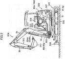
- FIG. 2 depicts an appearance of an electrically-driven hydraulic excavator in which the hydraulic drive system described above is incorporated.
- the electrically-driven hydraulic excavator includes a lower travel structure 501, an upper swing structure 502, and a front work implement 504 of the swing type.
- the front work implement 504 is configured from a boom 511, an arm 512, and a bucket 513.
- the upper swing structure 502 is swingable by rotation of the swing motor 3c with respect to the lower travel structure 501.
- a swing post 503 is provided at a front portion of the upper swing structure 502, and the front work implement 504 is attached for upward and downward movement to the swing post 503.
- the swing post 503 is rotatable in a horizontal direction with respect to the upper swing structure 502 by extension and contraction of the swing cylinder 3e, and the boom 511, arm 512, and bucket 513 of the front work implement 504 are rotatable in the upward and downward directions by extension and contraction of the boom cylinder 3a, arm cylinder 3b, and bucket cylinder 3d.
- a blade 506 that performs upward and downward movement by extension and contraction of the blade cylinder 3h is attached to a central frame 505 of the lower travel structure 501.
- the lower travel structure 501 travels by driving left and right crawler belts by rotation of the travel motors 3f and 3g.
- a cabin 508 is installed in the upper swing structure 502, and in the cabin 508, a driver's seat 521, operation devices 522 and 523 (in FIG. 2 , only those on the left side are depicted) for the boom, arm, bucket, and swing in which the pilot valves 60a to 60d are built), an operation device (not depicted) for boom-swing in which the pilot valve 60e is built, an operation device (not depicted) for the blade in which the pilot valve 60h is built, operation devices 524a and 524b (in FIG. 2 , only those on the left side are depicted) for travel in which pilot valves 60f and 60g are built, the gate lock lever 24, and so forth are provided.
- Each of the operation levers of the operation devices 522 and 523 is capable of being operated in an arbitrary direction with reference to cross directions from a neutral position.
- the operation lever of the operation device 522 on the left side is operated in the leftward and rightward directions, then the operation device 522 functions as an operation device for swing and the pilot valve 60c (refer to FIG. 13 ) for swing operates.
- the operation lever of the operation device 522 is operated in the forward and backward directions, then the operation device 522 functions as an operation device for the arm and the pilot valve 60b (refer to FIG. 13 ) for the arm operates.
- the operation device 523 When the operation lever of the operation device 523 on the right side is operated in the forward and backward directions, then the operation device 523 functions as an operation device for the boom and the pilot valve 60a for the boom operates. When the operation lever of the operation device 523 is operated in the leftward and rightward directions, then the operation device 523 functions as an operation device for the bucket and the pilot valve 60d (refer to FIG. 13 ) for the bucket operates.
- FIG. 3 depicts a functional block diagram of the controller 50 described above.
- the controller 50 includes a virtual limitation torque calculation section 51 for the main pumps 102 and 202 of the fixed displacement type, and a first electric motor rotational speed control section 52 and a second electric motor rotational speed control section 53.
- the virtual limitation torque calculation section 51 receives information (a voltage, a temperature, and so forth) from the battery management systems 171 and 271 as inputs thereto and performs a predetermined calculation process. Outputs of the virtual limitation torque calculation section 51 are inputted to the first electric motor rotational speed control section 52 and the second electric motor rotational speed control section 53 together with outputs from the pressure sensors 40 and 41 and the reference rotational speed instruction dial 56. The first electric motor rotational speed control section 52 and the second electric motor rotational speed control section 53 perform a predetermined calculation process using the inputs thereto and output results of the processes to the inverters 160 and 260, respectively.
- FIG. 4 depicts a functional block diagram of the virtual limitation torque calculation section 51 in the controller 50.
- the virtual limitation torque calculation section 51 includes first and second SOC estimation sections 51a and 51b, a differentiation section 51c, and first and second tables 51d and 51e.
- the first and second SOC estimation sections 51a and 51b receive information (a voltage, a temperature and so forth) from the battery management systems 171 and 271 as inputs thereto, respectively, calculate an SOC (State of Charge) indicative of a charge state of the power storage devices 170 and 270, and outputs SOC1 and SOC2 as the SOCs of them, respectively.
- ⁇ SOC is inputted to the first and second tables 51d and 51e, by which it is converted into a virtual limitation torque T1 of the main pump 102 and a virtual limitation torque T2 of the main pump 202 (horsepower control amounts).
- FIGS. 5A and 5B depict a characteristic of the first and second tables 51d and 51e.
- the characteristic of the table 51d is set such that, when the difference ⁇ SOC in a charge state has a positive value, a predetermined maximum value T1_max (fixed) is outputted as the virtual limitation torque T1. However, when ⁇ SOC has a negative value, the virtual limitation torque T1 that decreases as ⁇ SOC decreases is outputted, and when ⁇ SOC reaches -ASOC_0 in the proximity of a minimum value - ⁇ SOC_max, a minimum value T1_min is outputted as the virtual limitation torque T1.
- the characteristic of the table 51e is set to a reverse characteristic to the characteristic of the table 51d.
- the characteristic of the table 51e is set such that, when ⁇ SOC has a negative value, a maximum value T2_max is outputted as the virtual limitation torque T2.
- the characteristic of the table 51e is set such that, when ⁇ SOC has a positive value, the virtual limitation torque T2 that decreases as ⁇ SOC increases is outputted, and when ⁇ SOC reaches ASOC_0 in the proximity of the maximum value ⁇ SOC_max, a minimum value T2_min is outputted as the virtual limitation torque T2.
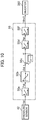
- FIG. 6 depicts a functional block diagram of the first and second electric motor rotational speed control sections 52 and 53 of the controller 50.
- a number in () indicates that it is a number in the case of the second electric motor rotational speed control section 53.
- outputs from the pressure sensors 40 and 41 are represented by Vps and Vplmax, respectively
- the output from the reference rotational speed instruction dial 56 is represented by Vec
- the output Vec is converted into a reference rotational speed N_0 by a rotational speed table 52d (53d).
- the reference rotational speed N_0 is converted into a target LS differential pressure Pgr in accordance with a differential pressure table 52e (53e).
- ⁇ P described above is inputted to a table 52g (53g), by which an increase/decrease amount ⁇ q of the virtual displacement is computed.
- ⁇ q described above is added to a virtual displacement q1** (q2**) after reflection of horsepower control before one control step stored in a memory and is further limited with a minimum value and a maximum value therefor by a table 52i (53i) to compute a virtual displacement q1* (q2*) before reflection of new horsepower.
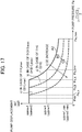
- the pump pressure Ps described hereinabove and the virtual limitation torque T1 (T2) that is output of the virtual limitation torque calculation section 51 in the controller 50 are inputted to the variable horsepower control table 52r (53r), by which they are converted into and outputted as a limit value q1*limit (q2*limit) for the virtual displacement as first and second allowable values for the absorption horsepower (consumption horsepower) of the main pumps 102 and 202.
- variable horsepower control tables 52r and 53r A characteristic of the variable horsepower control tables 52r and 53r is depicted in FIG. 7 .
- a characteristic indicated by a solid line A1 of the variable horsepower control tables 52r and 53r is a characteristic that simulates so-called horsepower control and is such a characteristic that, as the pump pressure Ps becomes high, the limit value q1*limit (q2*limit) for the virtual displacement of the pump pressure Ps decreases.
- the characteristic is such a characteristic that, as the virtual limitation torque T1 (T2) decreases, the characteristic simulating horsepower control changes like a broken line B1 or C1 as indicated by an arrow mark in FIG. 7 , and consequently, the degree of the limit becomes stronger, and the limit value q1*limit (q2*limit) for the virtual displacement decreases.
- a lower one of the virtual displacement q1* (q2*) before reflection of horsepower control described hereinabove and the limit value q1*limit (q2*limit) for the virtual displacement outputted from the variable horsepower control table 52r (53r) described above is selected as the virtual displacement q1** (q2**) after reflection of horsepower control by the minimum value selection section 52s (53s).
- the virtual displacement q1** (q2**) is multiplied by the reference rotational speed N_0 by a multiplication section 52j (53j), and a result of the multiplication is outputted as a target flow rate Q1d (Q2d).
- the target flow rate Q1d is multiplied by 1/qmax1 (1/qmax2) of a gain 52k (53k) so as to be converted into a target rotational speed N1d (N2d).
- the target rotational speed N1d (N2d) is converted into an input Vinv1 (Vinv2) to the inverter 160 (260) and outputted to the inverter 160 (260) by the table 52m (53m).
- the main pumps 102 and 202 of the fixed displacement type are first and second hydraulic pumps, and hydraulic fluids delivered from the first and second hydraulic pumps are merged in the common hydraulic fluid supply line 305 and supplied to the plurality of flow control valves 6a, 6b, 6c, 6c, 6e, 6f, 6g, and 6h and is further supplied to the plurality of actuators 3a, 3b, 3c, 3d, 3e, 3f, 3g, and 3h.
- the electric motors 101 and 201 are first and second electric motors that drive the main pumps 102 and 202 (first and second hydraulic pumps), respectively, and the power storage devices 170 and 270 are first and second power storage devices that supply electric power to the electric motors 101 and 201 (first and second electric motors), respectively.
- variable horsepower control table 52r and the minimum value selection section 52s in the electric motor rotational speed control section 52 of the controller 50 cooperates with the pressure sensor 40 to provide a first horsepower control device configured to decrease, when the delivery pressure of the main pump 102 (first hydraulic pump) increases, the delivery flow rate of the main pump 102 (first hydraulic pump) to control the absorption horsepower of the main pump 102 (first hydraulic pump) so as not to exceed the limit value q1*limit (first allowable value) for the virtual displacement.
- variable horsepower control table 53r and the minimum value selection section 53s in the electric motor rotational speed control section 53 of the controller 50 cooperate with the pressure sensor 40 to provide a second horsepower control device configured to decrease, when the delivery pressure of the main pump 202 (second hydraulic pump) increases, the delivery flow rate of the main pump 202 (second hydraulic pump) to control the absorption horsepower of the main pump 202 (second hydraulic pump) so as not to exceed the limit value q2*limit (second allowable value) for the virtual displacement.
- the virtual limitation torque calculation section 51 of the controller 50 and the variable horsepower control tables 52r and 53r in the electric motor rotational speed control sections 52 and 53 provide a horsepower distribution control section configured to change at least one of the limit values q1*limit and q2*limit (first and second allowable values) of the first and second horsepower control devices such that the charge state of the power storage device 170 (first power storage device) and the charge state of the power storage device 270 (second power storage device) become equal to each other.
- the main pumps 102 and 202 are hydraulic pumps of the fixed displacement type, and the first and second horsepower control devices are configured to control the rotational speeds of the main pump 102 (first hydraulic pump) and the main pump 202 (second hydraulic pump) to control the absorption horsepowers of the main pumps 102 and 202 (first and second hydraulic pumps) such that the absorption horsepower of the main pump 102 does not exceed the limit value q1*limit (first allowable value) and the absorption horsepower of the main pump 202 does not exceed the limit value q2*limit (second allowable value).
- Tables 52a to 52m in the electric motor rotational speed control section 52 of the controller 50 and the inverter 160 cooperate with the pressure sensors 40 and 41 and the reference rotational speed instruction dial 56 to provide a first flow control section configured to perform, when at least one of the operation devices 522 and 523, 524a, 524b, ... is operated, load sensing control for controlling a delivery flow rate of the main pump 102 (first hydraulic pump) such that the delivery pressure Ps of the main pump 102 (first hydraulic pump) becomes higher by a target differential pressure (target LS differential pressure Pgr) than the highest load pressure Plmax of the plurality of actuators 3a to 3h.
- target LS differential pressure Pgr target differential pressure
- Tables 53a to 53m in the electric motor rotational speed control section 53 of the controller 50 and the inverter 260 cooperate with the pressure sensors 40 and 41 and the reference rotational speed instruction dial 56 to provide a second flow control section configured to perform, when at least one of the operation devices 522, 523, 524a, 524b, ... is operated, load sensing control for controlling a delivery flow rate of the main pump 202 (second hydraulic pump) such that the delivery pressure Ps of the main pump 202 (second hydraulic pump) becomes higher by the target differential pressure (target LS differential pressure Pgr) than the highest load pressure Plmax of the plurality of actuators 3a to 3h.
- target differential pressure target LS differential pressure Pgr
- the first and second flow control sections described above are configured to control the rotational speeds of the main pumps 102 and 202 (first and second hydraulic pumps) respectively to control the delivery flow rate of the main pumps 102 and 202 (first and second hydraulic pumps) such that the delivery pressures of the main pumps 102 and 202 become higher by the target differential pressure than the highest load pressure of the plurality of actuators 3a to 3h.
- the first and second horsepower control devices described above are configured to control the delivery flow rates of the main pumps 102 and 202 (first and second hydraulic pumps) respectively, which are controlled by the load sensing control, such that the absorption horsepower of the main pump 102 (first hydraulic pump) does not exceed the limit value q1*limit (first allowable value) for the virtual displacement and the absorption horsepower of the main pump 202 (second hydraulic pump) does not exceed the limit value q2*limit (second allowable value) for the virtual displacement.
- the battery management system 171 and the first SOC estimation section 51a in the virtual limitation torque calculation section 51 of the controller 50 provide a first charge state estimation section configured to estimate a charge state of the power storage device 170 (first power storage device), and the battery management system 271 and the second SOC estimation section 51b in the virtual limitation torque calculation section 51 of the controller 50 provide a second power storage stage estimation section configured to estimate a charge state of the power storage device 270 (second power storage device).
- the differentiation section 51c and the first and second tables 51d and 51e in the virtual limitation torque calculation section 51 of the controller 50 provide a horsepower control amount calculation section configured to calculate, when the charge state of the power storage device 170 (first power storage device) estimated by the first charge state estimation section described above is lower than the charge state of the power storage device 270 (second power storage device) estimated by the second charge state estimation section described above, the virtual limitation torque T1 (first horsepower control amount) for decreasing the absorption horsepower of the main pump 102 (first hydraulic pump) and calculate, when the charge state of the power storage device 270 (second power storage device) estimated by the second charge state estimation section described above is lower than the charge state of the power storage device 170 (first power storage device) estimated by the first charge state estimation section described above, the virtual limitation torque T2 (second horsepower control amount) for decreasing the absorption horsepower of the main pump 202 (second hydraulic pump).
- a horsepower control amount calculation section configured to calculate, when the charge state of the power storage device 170 (first power storage device) estimated by the first charge state estimation section described
- variable horsepower control table 52r in the electric motor rotational speed control section 52 of the controller 50 provides a first allowable value changing section configured to change the limit value q1*limit (first allowable value) for the virtual displacement of the first horsepower control device described above on the basis of the virtual limitation torque T1 (first horsepower control amount) calculated by the horsepower control amount calculation section described above.
- the variable horsepower control table 53r that simulates the horsepower control characteristic in the electric motor rotational speed control section 53 of the controller 50 provides a second allowable value changing section configured to change the limit value q2*limit (second allowable value) for the virtual displacement of the second horsepower control device described above on the basis of the virtual limitation torque T2 (second horsepower control amount) calculated by the horsepower control amount calculation section described above.
- Hydraulic fluids delivered from the pilot pumps 130 and 230 of the fixed displacement type driven by the electric motors 101 and 201 are supplied to the hydraulic fluid supply line 31 through the check valves 133 and 233, respectively.
- the pilot relief valve 32 is connected, and a pilot primary pressure Ppi0 is generated in the hydraulic fluid supply line 31.
- the highest load pressure Plmax of the actuators 3a, 3b, 3c, 3d, 3e, 3f, 3g, and 3h is equal to the tank pressure through the flow control valves 6a, 6b, 6c, 6d, 6e, 6f, 6g, and 6h and the shuttle valves 9a, 9b, 9c, 9d, 9e, 9f, and 9g.
- the highest load pressure Plmax is introduced to the unload valve 15 and the pressure sensor 41.
- the pressure (pump pressure) Ps of the common hydraulic fluid supply line 305 is introduced to the pressure sensor 40.
- An output Vps of the pressure sensor 40 for the pump pressure Ps, an output Vplmax of the pressure sensor 41 for the highest load pressure Plmax and an output Vec of the reference rotational speed instruction dial 56 are inputted to the electric motor rotational speed control sections 52 and 53 in the controller 50 in addition to the virtual limitation torques T1 and T2 described hereinabove.
- the difference ⁇ P between the target LS differential pressure Pgr converted from the reference rotational speed N_0 by the table 52e and Pls described hereinabove is calculated by the differentiation section 52f.
- Ps is kept at a value a little higher than Pgr as described hereinabove
- Plmax is the tank pressure (estimated that the tank pressure ⁇ 0)
- the increase/decrease amount ⁇ q of the virtual displacement is added to the virtual displacement q1** after reflection of horsepower control before one control step, and after the resulting sum is limited with the minimum value and the maximum value by the table 52i, it becomes a new virtual displacement q1* after reflection of horsepower control. Since the increase/decrease amount ⁇ q of the virtual displacement has a negative value, by repeating the control step, the virtual displacement q1* before reflection of horsepower control is kept at the minimum value prescribed by the table 52i.
- the limit value q1*limit for the virtual displacement has a value on the solid line A1 in FIG. 7 .
- the virtual displacement q1** after reflection of horsepower control is multiplied by the reference rotational speed N_0 by the multiplication section 52j and becomes a target flow rate Q1d, and the target flow rate Q1d is converted into a target rotational speed N1d by multiplication by 1/qmax1 with the gain 52k and is further converted into an output Vnv1 to the inverter 160 by the table 52m.
- the rotational speed of the electric motor 101 is kept at a minimum rotational speed, and also the delivery flow rate from the main pump 102 of the fixed displacement type is kept at its minimum.
- the rotational speed of the electric motor 201 is kept at its minimum rotational speed, and also the delivery flow rate from the main pump 202 of the fixed displacement type is kept at a minimum.
- a case is considered in which the operation lever of the operation device 523 for boom is inputted in a raising direction, namely, in a direction in which the boom cylinder 3a is extended.
- the flow control valve 6a for the boom selects the leftward direction in the figure, and hydraulic fluids of the hydraulic fluid supply lines 105 and 205 from the main pumps 102 and 202 of the fixed displacement type are supplied to the bottom side of the boom cylinder 3a through the common hydraulic fluid supply line 305, pressure compensating valve 7a, and flow control valve 6a.
- the load pressure of the boom cylinder 3a is introduced as the highest load pressure Plmax to the pressure compensating valves 7a, 7b, 7c, 7d, 7e, 7f, 7g, and 7h, unload valve 15, and pressure sensor 41 through the load port of the flow control valve 6a, shuttle valves 9a, 9b, 9c, 9d, 9e, 9f, and 9g, and highest load hydraulic fluid line 306.
- the pressure (pump pressure Ps) of the common hydraulic fluid supply line 305 is introduced to the pressure sensor 40.
- the output Vps of the pressure sensor 40 for the pump pressure Ps, the output Vplmax of the pressure sensor 41 for the highest load pressure Plmax, and the output Vec of the reference rotational speed instruction dial 56 are inputted to the electric motor rotational speed control sections 52 and 53 in the controller 50 in addition to the virtual limitation torques T1 and T2 described hereinabove.
- Vps, Vplmax, and Vec described hereinabove are converted into Ps, Plmax, and N_0 by the tables 52a, 52b, and 52d, respectively.
- the difference ⁇ P between the target LS differential pressure Pgr converted from the reference rotational speed N_0 by the table 52e and Pls described above is calculated by the differentiation section 52f.
- ⁇ P is converted into an increase/decrease amount ⁇ q of the virtual displacement by the table 52g, since ⁇ P becomes a positive value higher than Pgr, also the increase/decrease amount ⁇ q of the virtual displacement has a positive value.
- the increase/decrease amount ⁇ q of the virtual displacement is added to the virtual displacement q1** after reflection of horsepower control before one control step and is limited with the minimum value and the maximum value by the table 52i, whereafter it becomes a new virtual displacement q1* before reflection of horsepower control.
- the pump pressure Ps is kept at a pressure higher by the target LS differential pressure Pgr than the highest load pressure Plmax.
- the virtual displacement q1** after reflection of horsepower control performs operation that simulates a main pump of variable displacement type that delivers a necessary flow rate within the range of the horsepower control characteristic prescribed by the variable horsepower control table 52r.
- the virtual displacement q1** after reflection of horsepower control is multiplied by the reference rotational speed N_0 by the multiplication section 52j and becomes a target flow rate Q1d, and the target flow rate Q1d is converted into a target rotational speed N1d by multiplication by 1/qmax1 by the gain 52k and is further converted into an output Vinv1 to the inverter 160 by the table 52m.
- the electric motor rotational speed control section 53 operates similarly, and the flow rates of hydraulic fluids delivered from the main pumps 102 and 202 of the fixed displacement type are merged and supplied to the flow control valve 6a.
- the virtual displacements q1** and q2** after reflection of horsepower control operate simulating a main pump of the variable displacement type that delivers a flow rate necessary within the range of the horsepower control characteristics prescribed by the variable horsepower control tables 52r and 53r to control the rotational speeds of the electric motors 101 and 201 such that the flow rate is implemented. Therefore, the virtual displacements q1** and q2** after reflection of horsepower control operate so as to control the rotational speed of the electric motor 101 such that the total delivery amount of the main pumps 102 and 202 of the fixed displacement type becomes equal to a flow rate required by the flow control valve 6a within a range within which the consumption horsepower of the main pumps 102 and 202 of the fixed displacement type does not exceed a certain value.
- the virtual limitation torques T1 and T2 that are outputs of the virtual limitation torque calculation section 51 are introduced to the variable horsepower control tables 52r and 53r of the electric motor rotational speed control sections 52 and 53, respectively.
- the virtual displacement q2** after reflection of horsepower control is multiplied by the reference rotational speed N_0 by the multiplication section 53j and becomes a target flow rate Q2d, and the target flow rate Q2d is converted into a target rotational speed N2d by multiplication by 1/qmax2 with the gain 53k and is further converted into an output Vinv2 to the inverter 260 by the table 53m.
- the rotational speed N2d is limited so as to be lower than the rotational speed N1d of the main pump 102 of the fixed displacement type.
- the power consumption of the pump increases in proportion to the pressure ⁇ flow rate and the pressure (pump pressure Ps) of the common hydraulic fluid supply line 305 is common and equal, since the flow rate of the main pump 202 is lower than the flow rate of the main pump 102 as described above, the power consumption of the main pump 202 becomes smaller than the power consumption of the main pump 102.
- the electric power consumption of the power storage device 270 from which electric power is supplied to the main pump 202 becomes lower than the electric power consumption of the power storage device 170 from which electric power is supplied to the main pump 102.
- the rate at which the SOC2 of the power storage device 270 decreases becomes lower than the rate at which the SOC1 of the power storage device 170 decreases, and this continues until after the SOC1 becomes equal to the SOC2.
- the virtual limitation torques T1 and T2 that are outputs of the virtual limitation torque calculation section 51 are introduced to the variable horsepower control tables 52r and 53r of the electric motor rotational speed control sections 52 and 53, respectively.
- the virtual displacement q1** after reflection of horsepower control is multiplied by the reference rotational speed N_0 by the multiplication section 52j and becomes a target flow rate Q1d, and the target flow rate Q1d is converted into a target rotational speed N1d by multiplication by 1/qmax1 by the gain 52k and is further converted into an output Vinv1 to the inverter 160 by the table 52m.
- the rotational speed N1d is limited so as to be lower than the rotational speed N2d of the main pump 202 of the fixed displacement type.
- the power consumption of the pump increases in proportion to the pressure ⁇ the flow rate and the pressure (pump pressure Ps) of the common hydraulic fluid supply line 305 is common and equal, since the flow rate of the main pump 102 is lower than the flow rate of the main pump 202 as described above, the power consumption of the main pump 102 becomes lower than the power consumption of the main pump 202.
- the electric power consumption of the power storage device 170 from which electric power is supplied to the main pump 102 becomes lower than the electric power consumption of the power storage device 270 from which electric power is supplied to the main pump 202.
- the rate at which the SOC1 of the power storage device 170 decreases becomes lower than the rate at which the SOC2 of the power storage device 270 decreases, and this continues until after the SOC1 and the SOC2 become equal to each other.
- the hydraulic drive system is configured such that it includes, in addition to the main pump 102, electric motor 101, and power storage device 170, the main pump 202, electric motor 201, power storage device 270, and the common hydraulic fluid supply line 305 in which hydraulic fluids delivered from the main pumps 102 and 202 are merged and the merged hydraulic fluid is supplied to the plurality of flow control valves 6a, 6b, 6c, 6d, 6e, 6f, 6g, and 6h and further supplied to the plurality of actuators 3a, 3b, 3c, 3d, 3e, 3f, 3g, and 3h, the rated voltages of various electric equipment such as a power storage device can be made common to that of an electrically-driven hydraulic work machine that requires lower horsepower.
- the hydraulic drive system includes the virtual limitation torque calculation section 51 and the variable horsepower control tables 52r and 53r and, in the case where the charge state of one of the power storage devices 170 and 270 becomes lower than the charge state of the other one of the power storage devices 170 and 270, the limit value q1*limit (q2*limit) of the virtual displacement is changed such that the charge state of the power storage device 170 and the charge state of the power storage device 270 become equal to each other thereby to suppress the power consumption of the hydraulic pump whose charge state is lower.
- the difference gradually decreases while the charge states of the power storage devices 170 and 270 are controlled so as to become equal to each other. Therefore, it is prevented that the power storage situation of only one of the power storage devices 170 and 270 decreases significantly, and the period of time within which the actuators of the electrically-driven hydraulic work machine obtain a predetermined speed.
- the two tables of the first and second tables 51d and 51e and the two motor rotational speed control sections of the electric motor rotational speed control sections 52 and 53 are provided in the virtual limitation torque calculation section 51 of the controller 50 and the limit value q1*limit or the limit value q2*limit (first or second allowable value) is changed such that, even in the case where the charge state of one of the two power storage devices 170 and 270 becomes lower than the charge state of the other power storage device, the charge state of the power storage device 170 and the charge state of the power storage device 270 become equal to each other, only one of the first and second tables 51d and 51e (for example, the first table 51d) and a corresponding one of the electric motor rotational speed control sections 52 and 53 (for example, the electric motor rotational speed control section 52) may be provided and the limit value q1*limit (first allowable value) may be changed such that, only in the case where the charge state of one (for example, the power storage device 270
- FIGS. 12A and 12B depict a first modification to the characteristic of the tables 51d and 51e.
- the characteristic of the tables 51d and 51e is set such that a fixed value (maximum value T1_max) is outputted as the virtual limitation torque T1 when ⁇ SOC has a positive value ( FIG. 5A ) or when ⁇ SOC has a negative value ( FIG. 5B )
- the virtual limitation torque T1 may otherwise be set such that, as ⁇ SOC increases ( FIG. 12A ) or decreases ( FIG. 12B ), the virtual limitation torque T1 further increases from a value equal to the maximum value T1_max to a value T1_od1.
- the SOC1 of the power storage device 170 and the SOC2 of the power storage device 270 can be made equal to each other in a shorter period of time.
- FIGS. 12C and 12D A second modification to the characteristics of the tables 51d and 51e is depicted in FIGS. 12C and 12D .
- the virtual limitation torque T1 is set such that, as ⁇ SOC increases from 0 ( FIG. 12A ) or decreases ( FIG. 12B ), the virtual limitation torque T1 further increases from a value equal to the maximum value T1_max to the value T1_od1
- the virtual limitation torque T1 is set such that a dead zone of 0 to ⁇ SOC_1 ( FIG. 12C ) or 0 to - ⁇ SOC_1 ( FIG. 12D ) is provided and the virtual limitation torque T1 further increases from a value equal to the maximum value T1_max to the value T1_od1 when ⁇ SOC goes out of the dead zone. This increases the electric power consumption of the power storage device with a higher SOC only in the case where ⁇ SOC goes out of the dead zone, and the stability of control can be achieved.
- FIG. 8 is a view depicting a hydraulic drive system of an electrically-driven hydraulic work machine (hydraulic excavator) according to a second embodiment of the present invention.
- the hydraulic drive system of the present embodiment further includes, in addition to the configuration of the first embodiment depicted in FIG. 1 , a check valve 180 (first check valve) that is provided in the hydraulic fluid supply line 105 of the main pump 102 of the fixed displacement type and blocks a flow of hydraulic fluid from the common hydraulic fluid supply line 305 to the main pump 102 of the fixed displacement type, and a check valve 280 (second check valve) that is provided in the hydraulic fluid supply line 205 of the main pump 202 of the fixed displacement type and blocks a flow of hydraulic fluid from the common hydraulic fluid supply line 305 to the main pump 202 of the variable displacement type.
- a check valve 180 first check valve
- second check valve second check valve
- the hydraulic drive system of the present embodiment includes an inputting device 58 and is configured such that, in such a case where the SOC of one of the power storage devices 170 and 270 decreases significantly in comparison with the other SOC or in such a case where only one of the power storage devices 170 and 270 is used and the electric power stored in the other power storage device is preserved while the total operating time period is to be increased in place of suppressing the work amount of the hydraulic work machine to be low, when an operator operates the inputting device 58, then the controller 50 stops one of the electric motors 101 and 201 for driving the main pumps 102 and 202 of the fixed displacement type.
- the structure of the other part is same as that of the first embodiment.
- the check valves 180 and 280 are provided in the hydraulic fluid supply lines 105 and 205, respectively, in the case where one of the electric motors 101 and 201 that respectively drive the main pumps 102 and 202 of the fixed displacement type is stopped, the pressure of the common hydraulic fluid supply line 305 is prevented from being applied to the delivery port of one of the main pumps 102 and 202 of the fixed displacement type which is being stopped.
- the check valves 180 and 280 prevent hydraulic fluid from leaking out from the main pump of the fixed displacement type in the stopping state to the tank, and power of the hydraulic fluid delivered from the main pump of the fixed displacement type in the driven state can be prevented from being lost wastefully by leak of the hydraulic fluid.
- FIG. 9 is a view depicting a hydraulic drive system of an electrically-driven hydraulic work machine (hydraulic excavator) according to a third embodiment of the present invention.
- the hydraulic drive system of the present embodiment includes an electric motor 301 (third electric motor), a pilot pump 30 of fixed displacement type that is driven by the electric motor 301, an inverter 360 that controls the rotational speed of the electric motor 301, a step-up/step-down chopper 361 that supplies electric power with a fixed voltage to the inverter 360, a pressure sensor 42 that is provided in the hydraulic fluid supply line 31 of the pilot pump 30 and detects a pressure of the hydraulic fluid supply line 31, namely, a delivery pressure (hereinafter referred to suitably as pump pressure) of the pilot pump 30, and a controller 55 that generates a rotational speed instruction signal to the inverter 360 on the basis of a detection signal of the pressure sensor 42 to control the inverter 360.
- a delivery pressure hereinafter referred to suitably as pump pressure
- the power storage device 270 is configured so as to supply electric power to the electric motor 201 through the step-up/step-down chopper 261 and the inverter 260 and supply electric power also to the electric motor 301 through the step-up/step-down chopper 361 and the inverter 360.
- Hydraulic fluid delivered from the pilot pump 30 of the fixed displacement type is supplied to the hydraulic fluid supply line 31.
- a gate lock valve 100 is connected which selects the pilot hydraulic fluid line on the downstream side so as to be connected to the hydraulic fluid supply line 31 or to the tank, and for the gate lock valve 100, a gate lock lever 24 is provided.
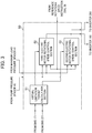
- FIG. 10 depicts a functional block diagram of the controller 55 in the third embodiment.
- the controller 55 includes a table 55a, another table 55b, an addition section 55c, a further table 55d, and a still further table 55f.
- the output from the pressure sensor 42 is represented by Vpi
- the output Vpi is converted into a pressure (pilot primary pressure Ppi) of the hydraulic fluid supply line 31 by the table 55a and is converted into an increase/decrease amount ⁇ qi of the virtual displacement qi of the pilot pump 30 by the table 55b.
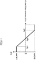
- FIG. 11 depicts a characteristic of the table 55b.
- the virtual displacement increase/decrease amount ⁇ qi of the pilot pump is added to a pilot pump virtual displacement qi before one control state by the addition section 55c to make a new pilot pump virtual displacement qi.
- the pilot pump virtual displacement qi is configured so as to be converted into a target rotational speed Npi of the electric motor 301 by the table 55d, and further converted into an input Vinv3 to the inverter 360 by the table 55f, and then outputted to the inverter 360.
- the structure of the other part is same as that of the first embodiment.
- the electric motor 301 is a third electric motor to which electric power is supplied by one of the power storage devices 170 and 270 (first and second power storage devices) to drive the pilot pump 30, and the controller 55 cooperates with the pressure sensor 42 and the inverter 360 to provide a pilot pump control device configured to control the rotational speed of the electric motor 301 (third electric motor) such that the pilot primary pressure Ppi generated by the pilot pump 30 becomes equal to a target pressure (target pilot primary pressure Ppi0).
- the rotational speed controlling function of the electric motors 101 and 201 for driving the main pumps 102 and 202 of the fixed displacement type is same as that of the first embodiment.
- the third embodiment is different from the first embodiment in that the pilot pump 30 of the fixed displacement type is driven independently by the electric motor 301 different from the electric motors 101 and 201 that respectively drive the main pumps 102 and 202 of the fixed displacement type.
- a case is considered in which the pressure (pilot primary pressure) of the hydraulic fluid supply line 31 is lower than the pilot primary pressure Ppi0.
- Vpi inputted by the pressure sensor 42 is converted into a pilot primary pressure Ppi by the table 55a.
- the pilot pump virtual displacement increase/decrease amount ⁇ qi has a positive value from 0 to ⁇ qi_max.
- the pilot pump virtual displacement increase/decrease amount ⁇ qi is added to a pilot pump virtual displacement qi before one control step, and in the case where Ppi is lower than the target pilot primary pressure Ppi0 as described above, the virtual displacement qi gradually increases.
- the pilot pump virtual displacement qi is converted into a target rotational speed Npi by the table 55d and into an output Vinv3 to the inverter 360 by the table 55f to control the rotational speed of the electric motor 301.
- the electric motor 301 increases its rotational speed until after the pressure (pilot primary pressure) of the hydraulic fluid supply line 31 becomes equal to the target pilot primary pressure.
- a case is considered in which the pressure (pilot primary pressure) of the hydraulic fluid supply line 31 is higher than the target pilot primary pressure Ppi0.
- Vpi inputted by the pressure sensor 42 is converted into a pilot primary pressure Ppi by the table 55a.
- the pilot pump virtual displacement increase/decrease amount ⁇ qi has a negative value between ⁇ qi_min and 0.
- the pilot pump virtual displacement increase/decrease amount ⁇ qi is added to the pilot pump virtual displacement qi before one control step, and in the case where Ppi is higher than the pilot primary pressure PpiO, the pilot pump virtual displacement qi gradually decreases as described hereinabove.
- the pilot pump virtual displacement qi is converted into a target rotational speed Npi by the table 55d and into an output Vinv3 to the inverter 360 by the table 55f to control the rotational speed of the electric motor 301.
- the electric motor 301 decreases its rotational speed until after the pressure (pilot primary pressure) of the hydraulic fluid supply line 31 becomes equal to the target pilot primary pressure.
- the controller 55 controls the rotational speed of the electric motor 301 such that the pressure (pilot primary pressure) of the hydraulic fluid supply line 31 becomes equal to the target pilot primary pressure (Ppi0).
- the charge state of the power storage device 270 tends to decrease earlier than the charge state of the power storage device 170.
- the rotational speed of the hydraulic pump (in the third embodiment, 202) that is driven by the electric motor to which electric power is supplied from the power storage device in the lower charge state (in the third embodiment, the power storage device 270) is limited and the electric power consumption of the electric motor is suppressed, and the charge states of the two power storage devices are controlled so as to become equal to each other again.
- FIG. 13 is a view depicting a hydraulic drive system of an electrically-driven hydraulic work machine (hydraulic excavator) according to a fourth embodiment of the present invention.
- the hydraulic drive system of the present embodiment includes electric motors 101, 201, 401, and 601, main pumps 122, 222, 422 and 622 of the variable displacement type driven by the electric motors 101, 201, 401, and 601, respectively, an electric motor 301, a pilot pump 30 of the fixed displacement type driven by the electric motor 301, a boom cylinder 3a, an arm cylinder 3b, a swing motor 3c, a bucket cylinder 3d, a swing cylinder 3e, travel motors 3f and 3g, and a blade cylinder 3h that are a plurality of actuators driven by hydraulic fluids delivered from the main pumps 122, 222, 422, and 622 of the variable displacement type, hydraulic fluid supply lines 105a, 105b, 205a, and 205b for introducing hydraulic fluids delivered from the main pumps 122, 222, 422, and 622 of the variable displacement type into the plurality of actuators 3a, 3b, 3c, 3d, 3e, 3f, 3g, and 3h,
- the control valve block 104 includes a plurality of directional selector valves 16a, 16d, 16e, 16g, and 16j that are connected to the common hydraulic fluid supply line 307 and control the directions and the flow rates of hydraulic fluids to be supplied to the plurality of actuators 3a, 3b, 3d, 3e, and 3g, a plurality of directional selector valves 16b, 16c, 16f, 16h and 16i that are connected to the common hydraulic fluid supply line 308 and control the directions and the flow rates of hydraulic fluids to be supplied to the plurality of actuators 3a, 3b, 3c, 3f, and 3h, check valves 80a, 80b, 80c, 80d, 80e, 80f, 80g, 80h, 80i, and 80j, and a main relief valve 14 that is provided on the downstream of the common hydraulic fluid supply lines 307 and 308 through the check valves 80e and 80f and controls the pressure of the common hydraulic fluid supply lines 307 and 308 so as not to become equal to or higher than
- the directional selector valve 16g To the downstream of the common hydraulic fluid supply line 307, the directional selector valve 16g is connected on the most upstream, and the directional selector valves 16a and 16d are connected in parallel to each other to the downstream of the directional selector valve 16g through the check valves 80a and 80b, respectively. Further, the directional selector valves 16j and 16e are connected in tandem connection to the downstream of the directional selector valves 16a and 16d through the check valves 80c and 80d such that the directional selector valve 16j is positioned on the upstream side with respect to the directional selector valve 16e.
- the directional selector valves 16c, 16b, 16i, and 16h are connected in parallel to each other through the check valves 80g, 80h, 80i, and 80j, respectively, and the directional selector valve 16f is connected in tandem connection to the downstream of the directional selector valve 16h.
- the plurality of the directional selector valves 16a, 16d, 16e, 16g, and 16j and the plurality of directional selector valves 16b, 16c, 16f, 16h and 16i are of the open center type, and the main pumps 122 and 222 and main pumps 422 and 622 and the control valve block 104 configure a hydraulic drive system of an open circuit.
- the main pumps 122, 222, 422, and 622 of the variable displacement type include regulator pistons 122a, 222a, 422a, and 622a for reducing, when the delivery pressure thereof becomes high, the displacement thereof to limit the torque, respectively.
- main pump 122 and the main pump 422 include regulator pistons 122b and 422b, respectively, for reducing, if the delivery pressure of one of them becomes high, the displacement of the main pump of the other of them to limit the torque
- main pump 222 and the main pump 622 include regulator pistons 222b and 622b for restricting, if the delivery pressure of one of them becomes high, the displacement of the main pump of the other of them to limit the torque.
- the main pumps 122, 222, 422, and 622 have springs 122f, 222f, 422f, and 622f for setting a limitation value q1*limit, a limitation value q2*limit, a limitation value q3*limit, and a limitation value q4*limit for the absorption horsepower, respectively.
- main pumps 122 and 422 include regulator pistons 122c and 422c for reducing the displacement of them by an external pressure (output pressure of a proportional solenoid valve 20 hereinafter described) to reduce the torque
- main pumps 222 and 622 include regulator pistons 222c and 622c for reducing the displacement of them by an external pressure (output pressure of a proportional solenoid valve 21 hereinafter described) to reduce the torque.
- the hydraulic drive system of the present embodiment includes a hydraulic fluid supply line 31 to which hydraulic fluid delivered from the pilot pump 30 of the fixed displacement type is introduced, a gate lock valve 100 that is connected to the hydraulic fluid supply line 31 and performs selection in regard to whether the pilot hydraulic fluid line on the downstream side is to be connected to the hydraulic fluid supply line 31 or the tank, and a gate lock lever 24 disposed on the operator's seat entrance side of the hydraulic work machine for performing a selection operation of the gate lock valve 100.
- the pilot hydraulic fluid line on the downstream side of the gate lock valve 100 is connected to a plurality of pilot valves 60a, 60b, 60c, 60d, 60e, 60f, 60g, and 60h provided on a plurality of operation devices 522, 523, 524a, 524b, ... (refer to FIG.
- the plurality of pilot valves 60a, 60b, 60c, 60d, 60e, 60f, 60g, and 60h generate a pilot operation pressure according to an operation amount based on hydraulic fluid of the pilot hydraulic fluid line on the downstream side of the gate lock valve 100, and the plurality of directional selector valves 16a, 16b, 16c, 16d, 16e, 16f, 16g, 16h, 16i, and 16j are controlled for selection by the pilot operation pressure.
- the hydraulic drive system of the present embodiment further includes inverters 160, 260, 460, and 660 for controlling the rotational speeds of the electric motors 101, 201, 401, and 601, a step-up/step-down chopper 161 for supplying electric power with a fixed voltage to the inverters 160 and 460, another step-up/step-down chopper 261 for supplying electric power with a fixed voltage to the inverters 260 and 660, an inverter 360 for controlling the rotational speed of the electric motor 301, a step-up/step-down chopper 361 for supplying electric power with a fixed voltage to the inverter 360, a power storage device 170 (first power storage device) connected so as to supply electric power to the electric motors 101 and 401 (first electric motors) through the step-up/step-down choppers 161 and the inverters 160 and 460, a power storage device 270 (second power storage device) connected so as to supply electric power to the electric motors 201 and 601 (second electric
- FIG. 14 depicts a functional block diagram of the controller 150 in the fourth embodiment.
- the controller 150 includes a proportional solenoid valve target current calculation section 151, gain tables 152a and 152b, multiplication sections 153a and 153b, a rotational speed instruction value table 154, and command value tables 155a and 155b.
- Outputs of the battery management systems 171 and 271 are inputted to the proportional solenoid valve target current calculation section 151, and an output of the proportional solenoid valve target current calculation section 151 is outputted to the proportional solenoid valves 20 and 21.
- a maximum operation pilot pressure of the boom cylinder 3a, arm cylinder 3b, bucket cylinder 3d, swing cylinder 3e and right travel motor 3g is inputted to the controller 150 through the pressure sensor 43, and a maximum operation pilot pressure of the boom cylinder 3a (in the raising direction only), arm cylinder 3b, swing motor 3c, blade cylinder 3h and left travel motor 3f is inputted to the controller 150 through the pressure sensor 44.
- Outputs from the pressure sensors 43 and 44 are inputted to the gain tables 152a and 152b, by which they are converted into gains N_gain1 and N_gain2 within a range of 0 to 100%, respectively. Further, an output from the reference rotational speed instruction dial 56 is converted into a reference rotational speed N_0 by the rotational speed instruction value table 154.
- the reference rotational speed N_0 that is an output of the rotational speed instruction value table 154 is multiplied by the gains N_gain1 and N_gain2 by the multiplication sections 153a and 153b to obtain target rotational speeds N1d and N2d for the inverters 160 and 260 and the inverters 460 and 660, respectively.
- the target rotational speeds N1d and N2d are inputted to the command value tables 155a and 155b and converted into command values Vinv1 and Vinv2 for the inverters 160 and 260 and the inverters 460 and 660, respectively, and they are outputted to the inverters 160 and 260 and the inverters 460 and 660.
- FIG. 15 depicts a functional block diagram of the proportional solenoid valve target current calculation section 151 in the controller 150 in the fourth embodiment.
- the proportional solenoid valve target current calculation section 151 includes first and second SOC estimation sections 151a and 151b, a differentiation section 151c, and first and second tables 151d and 151e.
- the difference ⁇ SOC is inputted to the first and second tables 151d and 151e, by which they are converted into target currents I1 and I2 (horsepower control amounts), which are outputted to the proportional solenoid valves 20 and 21.
- FIGS. 16A and 16B depict characteristics of the first and second tables 151d and 151e.
- the characteristic of the first table 151d is set such that, when ⁇ SOC has a positive value, 0 is outputted as the target current I1 of the proportional solenoid valve 20, and when ⁇ SOC has a negative value, as ⁇ SOC decreases from the dead zone - ⁇ SOC_2, the target current I1 of the proportional solenoid valve 20 increases, and when ⁇ SOC reaches - ⁇ SOC_0 in the proximity of the maximum value - ⁇ SOC_max, a maximum value I_max is outputted as the target current I1.
- the characteristic of the second table 151e is set reverse to the characteristic of the first table 151d.
- the characteristic of the second table 151e is set such that, when ⁇ SOC has a negative value, 0 is outputted as the target current 12 of the proportional solenoid valve 21, and when ⁇ SOC has a positive value, as ⁇ SOC increases from the dead zone ⁇ SOC_2, the target current 12 of the proportional solenoid valve 21 increases, and when ⁇ SOC reaches ⁇ SOC_0 in the proximity of the maximum value ⁇ SOC_max, a maximum value I_max is outputted as the target current 12.
- FIG. 17 depicts a horsepower control characteristic by the regulator pistons 122a and 422a, regulator pistons 122b and 422b, and regulator pistons 122c and 422c of the main pumps 122 and 422 of the variable displacement type. Further, in FIG. 17 , a horsepower control characteristic by the regulator pistons 222a and 622a, regulator pistons 222b and 622b, and regulator pistons 222c and 622c of the main pumps 222 and 622 of the variable displacement type is depicted in parentheses.
- the regulator pistons 122a, 422a, 122b, and 422b have a characteristic that, after the average value Pa of the delivery pressures P1 and P2 exceeds Pa_a, as it becomes higher, the displacement qq1 of the main pumps 122 and 422 decreases.
- the horsepower control characteristic becomes such a characteristic that it varies as indicated with a broken line B2 or C2 as indicated by an arrow mark in FIG. 17 to increase the degree of the limitation stronger and the displacement qq1 of the main pumps 122 and 422 decreases.
- the main pumps 122 and 222 (or 422 and 622) of the variable displacement type are first and second hydraulic pumps, and hydrauslic fluids delivered from the first and second hydraulic pumps are merged in the common hydraulic fluid supply line 307 (or 308) and supplied to the plurality of flow control valves 16a, 16b, 16d, 16e, and 16g (or 16a, 16b, 16c, 16f, and 16h) and further supplied to the plurality of actuators 3a, 3b, 3d, 3e, 3f, and 3g (or 3a, 3b, 3d, 3e, and 3g).
- the electric motors 101 and 201 are first and second electric motors that drive the main pumps 122 and 222 (or 422 and 622) (first and second hydraulic pumps), respectively, and the power storage devices 170 and 270 are first and second power storage devices that supply electric power to the electric motors 101 and 201 (or 401 and 601) (first and second motors), respectively.
- the regulator piston 122a (or 422a) provides a first horsepower control device configured to decrease, when the delivery pressure of the main pump 122 (or 422) (first hydraulic pump) increases, the delivery flow rate of the main pump 122 (or 422) (first hydraulic pump) to control the absorption horsepower of the main pump 122 (or 422) (first hydraulic pump) so as not to exceed the limitation value q1*limit (first allowable value), and the regulator piston 222a (or 622a) provides a second horsepower control device configured to decrease, when the delivery pressure of the main pump 222 (or 622) (second hydraulic pump) increases, the delivery flow rate of the main pump 222 (or 622) (second hydraulic pump) to control the absorption horsepower of the main pump 222 (or 622) (second hydraulic pump) so as not to exceed the limitation value q2*limit (second allowable value) .
- the proportional solenoid valve target current calculation section 151 cooperates with the battery management systems 171 and 271 to provide a horsepower distribution control section configured to change at least one of the limitation value q1*limit (first allowable value) and the limitation value q2*limit (second allowable value) of the first and second horsepower control devices such that the charge state of the power storage device 170 (first power storage device) and the charge state of the power storage device 270 (second power storage device) become equal to each other.
- the main pumps 122 and 222 are hydraulic pumps of the variable displacement type
- the first horsepower control device are configured to control the displacements of the main pump 122 (or 422) (first hydraulic pump) and the main pump 222 (or 622) (second hydraulic pump) to control the absorption horsepower of the main pumps 122 and 222 (or 422 and 622) (first and second hydraulic pumps) such that the absorption horsepower of the main pump 122 (or 422) (first hydraulic pump) does not exceed the limitation value q1*limit (first allowable value) and the absorption horsepower of the main pump 222 (or 622) (second hydraulic pump) does not exceed the limitation value q2*limit (second allowable value).
- the gain table 152a (152b), multiplication section 153a (153b), rotational speed instruction value table 154, command value table 155a (155b), and inverter 160 (or 460) provide a first flow control section configured to perform when at least one of the operation devices 522, 523, 524a, 524b, ...
- the first and second flow control sections described above are configured to control the rotational speeds of the main pumps 122 and 222 (or 422 and 622) (first and second hydraulic pumps) respectively to control the delivery flow rates of the main pumps 122 and 222 (or 422 and 622) (first and second hydraulic pumps) as the required flow rate increases
- the first and second horsepower control devices are configured to control the delivery flow rates of the main pumps 122 and 222 (or 422 and 622) (first and second hydraulic pumps) respectively, which are controlled by positive flow control, such that the absorption horsepower of the main pump 122 (or 422) (first hydraulic pump) does not exceed the limitation value q1*limit (or q3*limit) (first allowable value) and the absorption horsepower of the main pump 222 (or 622) (second hydraulic pump) does not exceed the limitation value q2*limit (or q4*limit).
- the battery management system 171 and the first SOC estimation section 151a in the proportional solenoid valve target current calculation section 151 of the controller 150 provide a first charge state estimation section configured to estimate the storage state of the power storage device 170 (first power storage device), and the battery management system 271 and the second SOC estimation section 151b in the proportional solenoid valve target current calculation section 151 of the controller 150 provide a second charge state estimation section configured to estimate the charge state of the power storage device 270 (second power storage device) .
- the differentiation section 151c in the proportional solenoid valve target current calculation section 151 of the controller 150 and the first and second tables 151d and 151e provide a horsepower control amount calculation section configured to calculate, when the charge state of the power storage device 170 (first power storage device) estimated by the first charge state estimation section is lower than the charge state of the power storage device 270 (second power storage device) estimated by the second charge state estimation section, a target current I1 (first horsepower control amount) of the proportional solenoid valve 20 for decreasing the absorption horsepower of the main pump 122 (or 422) (first hydraulic pump), and calculate, when the charge state of the power storage device 270 (second power storage device) estimated by the second charge state estimation section is lower than the charge state of the power storage device 170 (first power storage device) estimated by the first charge state estimation section, a target current 12 (second horsepower control amount) of the proportional solenoid valve 21 for decreasing the absorption horsepower of the main pump 222 (or 622) (second hydraulic pump).
- a horsepower control amount calculation section configured to calculate
- the proportional solenoid valve 20 and the regulator piston 122c (or 422c) of the main pump 122 (or 422) provide a first allowable value changing section configured to change the limitation value q1*limit (or q3*limit) (first allowable value) of the first horsepower control device on the basis of the target current I1 (first horsepower control amount) of the proportional solenoid valve 20 calculated by the horsepower control amount calculation section.
- the proportional solenoid valve 21 and the regulator piston 222c (or 622c) of the main pump 222 (or 622) provide a second allowable value changing section configured to change the limitation value q2*limit (or q4*limit) (second allowable value) of the second horsepower control device on the basis of the target current 12 (second horsepower control amount) of the proportional solenoid valve 21 calculated by the horsepower control amount calculation section.
- the pressure of the hydraulic fluid supply line 31 is kept at the pilot primary pressure Ppi0 by controlling the rotational speed of the electric motor 301 for driving the pilot pump 30 of the fixed displacement type.
- FIG. 15 depicts a functional block diagram of the proportional solenoid valve target current calculation section 151.
- an output from the reference rotational speed instruction dial 56 is converted into a reference rotational speed N_0 by the rotational speed instruction value table 154 and multiplied by the N_gain1 and N_gain2 by the multiplication sections 153a and 153b so as to be converted into target rotational speeds N1d and N2d and is further converted into an output Vinv1 to the inverters 160 and 260 and an output Vinv2 to the inverters 460 and 660 by the command value tables 155a and 155b.
- N_gain1 and N_gain2 are kept at a minimum value (for example, 0%) as described hereinabove, both of the output Vinv1 to the inverters 160 and 260 and the output Vinv2 to the inverters 460 and 660 are kept at a minimum value.
- hydraulic fluids delivered from the main pumps 122 and 222 pass the hydraulic fluid supply lines 105a and 105b, respectively, and are merged in the hydraulic fluid supply line 307 and then supplied to the P1 port of the control valve block 104.
- hydraulic fluids delivered from the main pumps 422 and 622 pass through the hydraulic fluid supply lines 205a and 205b, respectively, and are merged in the hydraulic fluid supply line 308 and then supplied to the P2 port of the control valve block 104.
- a case is considered in which the operation lever for the boom is inputted in a raising direction, namely, in a direction in which the boom cylinder 3a extends.
- the pilot valve 60a for the boom operation is operated, and an operation pilot pressure is generated in a1.
- both of the directional selector valves 16a and 16i for the boom select the rightward direction in the figure, and hydraulic fluids supplied from the main pumps 122 and 222 of the variable displacement type through the hydraulic fluid supply line 307 and hydraulic fluids supplied from the main pumps 422 and 622 of the variable displacement type through the hydraulic fluid supply line 308 are merged and supplied to the bottom side of the boom cylinder 3a.
- the output pressure of the pilot valve 60a for the boom operation is introduced to the pressure sensor 43 through the shuttle valves 19a, 19e, 19f, 19g, and 19h and simultaneously introduced to the pressure sensor 44 through the shuttle valve 19p.
- Output Vpc1 and Vpc2 of the pressure sensors 43 and 44 are introduced to the gain tables 152a and 152b, from which N_gain1 and N_gain2 are outputted in response to an output of the pilot valve 60a for the boom operation.
- both of N_gain1 and N_gain2 become a maximum value 100%.
- an output from the reference rotational speed instruction dial 56 to be converted into a reference rotational speed N_0 by the rotational speed instruction value table 154 is multiplied by the N_gain1 and N_gain2 described above by the multiplication sections 153a and 153b so as to be converted into target rotational speeds N1d and N2d, respectively, and are further converted into an output Vinv1 to the inverters 160 and 260 and an output Vinv2 to the inverters 460 and 660 by the command value tables 155a and 155b, respectively.
- both of the input Vinv1 to the inverters 160 and 260 and the output Vinv2 to the inverters 460 and 660 come to have a value same as that of an input from the reference rotational speed instruction dial 56.
- the horsepower control characteristic of the main pumps 122, 222, 422, and 622 of the variable displacement type becomes such as indicated by a solid line A2 in FIG. 17 , and at the pump delivery pressure of Pa_bmr, the displacement of the main pumps 122 and 222 of the variable displacement type is limited to qqbmr1 and the displacement of the main pumps 422 and 622 of the variable displacement type is limited to qqbmr2.
- the main pumps 122, 222, 422, and 622 supply hydraulic fluids with displacements that depend upon respective horsepower control characteristics at a rotational speed according to a boom raising operation input.
- the displacement of the main pumps 222 and 622 of the variable displacement type becomes qqbmr2_min, and qqbmr2_min ⁇ qqbmr1 is satisfied.
- the rotational speeds of the electric motors 101 and 401 for driving the main pumps 122 and 422 of the variable displacement type and the electric motors 201 and 601 for driving the main pumps 422 and 622 of the variable displacement type depends only on the boom raising operation amount, since the displacement qq1 of the main pumps 122 and 422 of the variable displacement type and the displacement qq2 of the main pumps 222 and 622 of the variable displacement type have a difference therebetween as described above, the flow rates of hydraulic fluids delivered by the main pumps 222 and 622 of the variable displacement type are lower than the flow rates of hydraulic fluids delivered by the main pumps 122 and 422 of the variable displacement type.
- the power consumption of a pump increases in proportion to the pressure ⁇ the flow rate and, upon boom raising operation, the pressures of the hydraulic fluid supply lines 105 and 205 are equal to each other, since the delivery flow rates of the main pumps 222 and 622 are lower than the delivery flow rates of the main pumps 122 and 422 as described hereinabove, the power consumption of the main pumps 222 and 622 is lower than the power consumption of the main pumps 122 and 422.
- the electric power consumption of the power storage device 270 from which electric power is supplied to the main pumps 222 and 622 is lower than the electric power consumption of the power storage device 170 from which electric power is supplied to the main pumps 122 and 422.
- the rate at which the SOC2 of the power storage device 270 decreases is lower than the rate at which the SOC1 of the power storage device 170 decreases, and this continues until after the SOC1 and the SOC2 become equal to each other.
- the hydraulic drive system is configured such that, in addition to the main pumps 122 and 422, electric motors 101 and 401, and power storage device 170, the main pumps 222 and 622, electric motors 401 and 601, and power storage device 270 as well as the common hydraulic fluid supply line 307 in which hydraulic fluids delivered from the main pumps 122 and 222 are merged and the common hydraulic fluid supply line 308 in which hydraulic fluids delivered from the main pumps 422 and 622 are merged are provided and the merged hydraulic fluid is supplied to the plurality of directional selector valves (flow control valves) 16a, 16d, 16e, 16g, and 16j or the plurality of directional selector valves (flow control valves) 16b, 16c, 16f, 16h, and 16i and is further supplied to the plurality of actuators 3a, 3b, 3c, 3d, 3e, and 3g or the plurality of actuators 3a, 3b, 3c, 3f, and 3h, the rated voltage of various electric equipment such as power
- the proportional solenoid valve target current calculation section 151 and the proportional solenoid valves 20 and 21 are provided and, in the case where the charge state of one of the power storage devices 170 and 270 becomes lower than the charge state of the other one of the power storage devices 170 and 270, the limit value q1*limit (q2*limit) of horsepower control of the main pumps 122 and 222 (or 422 and 622) is changed such that the charge state of the power storage device 170 and the charge state of the power storage device 270 become equal to each other thereby to suppress the power consumption of the hydraulic pump whose charge state is lower, even in the case where there is a difference in mechanical efficiency of the main pumps 122 and 222 or 422 and 622 and efficiency of electric equipment such as the inverters 160 and 260 or 460 and 660 or the step-up/step-down choppers 161 and 261, or even in the case where there is a difference between the electric power consumption amounts or the charge state characteristics of the power storage devices 170 and 270, the difference gradually
- first and second tables 151d and 151e for example, the first table 151d
- a corresponding one of the proportional solenoid valves 20 and 21 may be provided such that, only in the case where the charge state of one (for example, the power storage device 270) of the two power storage devices 170 and 270 becomes lower than the charge state of the other power storage device (for example, the power storage device 170), the limit value q1*limit (first allowable value) is changed such that the charge state of the power storage device 170 and the charge state of the power storage device 270) become equal to each other.
Landscapes
- Engineering & Computer Science (AREA)
- General Engineering & Computer Science (AREA)
- Mining & Mineral Resources (AREA)
- Civil Engineering (AREA)
- Structural Engineering (AREA)
- Physics & Mathematics (AREA)
- Fluid Mechanics (AREA)
- Mechanical Engineering (AREA)
- Power Engineering (AREA)
- Operation Control Of Excavators (AREA)
- Fluid-Pressure Circuits (AREA)
Claims (8)
- Hydraulisches Antriebssystem für eine elektrisch angetriebene hydraulische Arbeitsmaschine, mit einer ersten Hydraulikpumpe (102), einer Vielzahl von Stellgliedern (3a-3h), die durch von der ersten Hydraulikpumpe (102) geliefertes Hydraulikfluid angetrieben werden, einer Vielzahl von Strömungssteuerventilen (6a-6h), die Richtungen und Durchflüsse der der Vielzahl von Stellgliedern (3a-3h) zuzuführenden Hydraulikfluide steuern, einem ersten Elektromotor (101), der die erste Hydraulikpumpe (102) antreibt, einer ersten Energiespeichervorrichtung (170), die den ersten Elektromotor (101) mit elektrischer Energie versorgt, und einer ersten Leistungssteuervorrichtung (40, 52r, 52s), die so konfiguriert ist, dass sie, wenn ein Förderdruck der ersten Hydraulikpumpe (102) ansteigt, einen Förderdurchfluss der ersten Hydraulikpumpe (102) verringert, um eine Absorptionsleistung der ersten Hydraulikpumpe (102) so zu steuern, dass sie einen ersten zulässigen Wert (q1*Grenzwert) nicht überschreitet,
dadurch gekennzeichnet, dass
das hydraulische Antriebssystem umfasst:eine zweite Hydraulikpumpe (202;eine gemeinsame Hydraulikfluidzufuhrleitung (305), in der die von der ersten und der zweiten Hydraulikpumpe (102, 202) geförderten Hydraulikfluide zusammengeführt und der Vielzahl von Strömungssteuerventilen (6a-6h) zugeführt werden;einen zweiten Elektromotor (201), der die zweite Hydraulikpumpe (202) antreibt;eine zweite Energiespeichervorrichtung (270), die den zweiten Elektromotor (201) mit elektrischer Energie versorgt;eine zweite Leistungssteuervorrichtung (40, 53r, 53s), die so konfiguriert ist, dass sie, wenn ein Förderdruck der zweiten Hydraulikpumpe (202) ansteigt, einen Förderdurchfluss der zweiten Hydraulikpumpe (202) verringert, um eine Absorptionsleistung der zweiten Hydraulikpumpe (202) so zu steuern, dass ein zweiter zulässiger Wert (q2*Grenzwert) nicht überschritten wird; undein Controller (50) mit einem Leistungsverteilungs-Steuerabschnitt (51, 52r, 53r), der so konfiguriert ist, dass er mindestens einen der ersten und zweiten zulässigen Werte (q1*Grenzwert, q2*Grenzwert) der ersten und zweiten Leistungssteuervorrichtungen (40, 52r, 52s, 53r, 53s) so ändert, dass ein Ladezustand der ersten Energiespeichervorrichtung (170) und ein Ladezustand der zweiten Energiespeichervorrichtung (270) einander gleich werden. - Hydraulisches Antriebssystem für eine elektrisch angetriebene hydraulische Arbeitsmaschine nach Anspruch 1, wobeijede der ersten und zweiten Hydraulikpumpen (102, 202) eine Hydraulikpumpe mit fester Verdrängung ist, unddie erste und die zweite Leistungssteuervorrichtung (40, 52r, 52s, 53r, 53s) so konfiguriert sind, dass sie die Drehzahlen der ersten bzw. der zweiten Hydraulikpumpe (102, 202) steuern, um die Absorptionsleistungen der ersten und der zweiten Hydraulikpumpe (102, 202)) so zu steuern, dass die Absorptionsleistung der ersten Hydraulikpumpe (102) den ersten zulässigen Wert (q1*Grenzwert) nicht überschreitet und die Absorptionsleistung der zweiten Hydraulikpumpe (202) den zweiten zulässigen Wert (q2*Grenzwert) nicht überschreitet.
- Hydraulisches Antriebssystem für eine elektrisch angetriebene hydraulische Arbeitsmaschine nach Anspruch 1, wobeijede der ersten und zweiten Hydraulikpumpen (122, 222) eine Hydraulikpumpe mit variabler Verdrängung ist, unddie erste und die zweite Leistungssteuervorrichtung (122a, 222a) so konfiguriert sind, dass sie die Verdrängungen der ersten bzw. der zweiten Hydraulikpumpe (122, 222) steuern, um die Absorptionsleistungen der ersten und der zweiten Hydraulikpumpe (122, 222) so zu steuern, dass die Absorptionsleistung der ersten Hydraulikpumpe (122) den ersten zulässigen Wert (q1*Grenzwert) nicht überschreitet und die Absorptionsleistung der zweiten Hydraulikpumpe (222) den zweiten zulässigen Wert (q2*Grenzwert) nicht überschreitet.
- Hydraulisches Antriebssystem für eine elektrisch angetriebene hydraulische Arbeitsmaschine nach Anspruch 1, ferner umfassend:eine Vielzahl von Betätigungsvorrichtungen (522, 523, 524a, 524b, ...), die die Betätigung der Vielzahl von Stellgliedern (3a-3h) steuern, wobei der Controller (50) ferner umfassteinen ersten Strömungssteuerabschnitt (52a-52m, 160), der so konfiguriert ist, dass er, wenn mindestens eine der Vielzahl von Betätigungsvorrichtungen (522, 523, 524a, 524b, ...) betätigt wird, eine Lasterfassungssteuerung durchführt, um einen Förderdurchfluss der ersten Hydraulikpumpe (102) so zu steuern, dass der Förderdruck der ersten Hydraulikpumpe (102) um einen Soll-Differenzdruck (Pgr) höher als ein höchster Lastdruck der Vielzahl von Stellgliedern (3a-3h) ist, undeinen zweiten Strömungssteuerabschnitt (53a-53m, 260), der so konfiguriert ist, dass er, wenn mindestens eine der Vielzahl von Betätigungsvorrichtungen (522, 523, 524a, 524b, ...) betätigt wird, eine Lasterfassungssteuerung durchführt, um einen Förderdurchfluss der zweiten Hydraulikpumpe (202) so zu steuern, dass der Förderdruck der zweiten Hydraulikpumpe (202) um einen Soll-Differenzdruck (Pgr) höher als ein höchster Lastdruck der Vielzahl von Stellgliedern (3a-3h) ist, und,die ersten und zweiten Strömungssteuerabschnitte (52a-52m, 160, 53a-53m, 260) so konfiguriert sind, dass sie die Drehzahlen der ersten bzw. zweiten Hydraulikpumpen (102, 202) steuern, um die Förderdurchflüsse der ersten und zweiten Hydraulikpumpen (102, 202) so zu steuern, dass die Förderdrücke der ersten und zweiten Hydraulikpumpen (102, 202) um den Soll-Differenzdruck (Pgr) höher als der höchste Lastdruck der Mehrzahl von Stellgliedern (3a-3h) werden, unddie erste und die zweite Leistungssteuervorrichtung (40, 52r, 52s, 53r, 53s) so konfiguriert sind, dass sie die Förderdurchflüsse der ersten bzw. der zweiten Hydraulikpumpe (102, 202), die durch die Lasterfassungssteuerung gesteuert werden, so steuern, dass die Absorptionsleistung der ersten Hydraulikpumpe (102) den ersten zulässigen Wert (q1*Grenzwert) nicht überschreitet und die Absorptionsleistung der zweiten Hydraulikpumpe (202) den zweiten zulässigen Wert (q2*Grenzwert) nicht überschreitet.
- Hydraulisches Antriebssystem für eine elektrisch angetriebene hydraulische Arbeitsmaschine nach Anspruch 1, ferner umfassend:eine Vielzahl von Betätigungsvorrichtungen (522, 523, 524a, 524b, ...), die die Betätigung der Vielzahl von Stellgliedern (3a-3h) steuern, wobei der Controller (150) ferner umfassteinen ersten Strömungssteuerabschnitt (152a, 153a, 154, 155a, 160), der so konfiguriert ist, dass er, wenn mindestens eine der Vielzahl von Betätigungsvorrichtungen (522, 523, 524a, 524b, ...) betätigt wird, eine positive Strömungssteuerung zur Steuerung eines Förderdurchflusses der ersten Hydraulikpumpe (122) durchführt, wenn ein erforderlicher Durchfluss durch die Betätigungsvorrichtung zunimmt, undeinen zweiten Strömungssteuerabschnitt (152a, 153a, 154, 155a, 260), der so konfiguriert ist, dass er, wenn mindestens eine der Vielzahl von Betätigungsvorrichtungen (522, 523, 524a, 524b, ...) betätigt wird, eine positive Strömungssteuerung zur Steuerung eines Förderdurchflusses der zweiten Hydraulikpumpe (222) durchführt, wenn ein erforderlicher Durchfluss durch die Betätigungsvorrichtung zunimmt,der erste und der zweite Strömungssteuerabschnitt (152a, 153a, 154, 155a, 160, 260) so konfiguriert sind, dass sie die Drehzahlen der ersten bzw. der zweiten Hydraulikpumpe (122, 222) steuern, um die Förderdurchflüsse der ersten und der zweiten Hydraulikpumpe (122, 222) zu steuern, wenn der erforderliche Durchfluss steigt, unddie erste und die zweite Leistungssteuervorrichtung (122a, 222a) so konfiguriert sind, dass sie die Förderdurchflüsse der ersten bzw. der zweiten Hydraulikpumpe (122, 222), die durch die positive Strömungsteuerung gesteuert werden, so steuern, dass die Absorptionsleistung der ersten Hydraulikpumpe (122) den ersten zulässigen Wert (q1*Grenzwert) nicht überschreitet und die Absorptionsleistung der zweiten Hydraulikpumpe (222) den zweiten zulässigen Wert (q2*Grenzwert) nicht überschreitet.
- Hydraulisches Antriebssystem für eine elektrisch angetriebene hydraulische Arbeitsmaschine nach Anspruch 1, wobei
der Abschnitt (51, 52r, 53r) zur Steuerung der Leistungsverteilung des Controllers (50) umfasst:einen ersten Ladezustandsschätzabschnitt (171, 51a), der so konfiguriert ist, dass er einen Ladezustand der ersten Energiespeichervorrichtung (170) schätzt,einen zweiten Ladezustandsschätzabschnitt (271, 51b), der so konfiguriert ist, dass er einen Ladezustand der zweiten Energiespeichervorrichtung (270) schätzt,einen Berechnungsabschnitt (51c, 51d, 51e) für den Leistungssteuerbetrag, der so konfiguriert ist, dass er, wenn der durch den ersten Ladungszustandsschätzabschnitt (171, 51a) geschätzte Ladezustand der ersten Energiespeichervorrichtung (170) niedriger als der durch den zweiten Ladungszustandsschätzabschnitt (271, 51b) geschätzte Ladezustand der zweiten Energiespeichervorrichtung (270) ist, einen ersten Leistungssteuerbetrag zum Verringern der Absorptionsleistung der ersten Hydraulikpumpe (102) berechnet und, wenn der durch den zweiten Ladungszustandsschätzabschnitt (271, 51b) geschätzte Ladezustand der zweiten Energiespeichervorrichtung (270) niedriger als der durch den ersten Ladungszustandsschätzabschnitt (171, 51a) geschätzte Ladezustand der ersten Energiespeichervorrichtung (170) ist, einen zweiten Leistungssteuerbetrag zum Verringern der Absorptionsleistung der zweiten Hydraulikpumpe (202) berechnet, einen Abschnitt (52r) zur Änderung eines ersten zulässigen Werts, der so konfiguriert ist, dass er den ersten zulässigen Wert (q1*Grenzwert) für die erste Leistungssteuervorrichtung (40, 52r, 52s) auf der Grundlage des ersten Leistungssteuerbetrags ändert, der von dem Berechnungsabschnitt für den Leistungssteuerbetrag berechnet ist, undeinen Abschnitt (53r) zur Änderung eines zweiten zulässigen Werts, der so konfiguriert ist, dass er den zweiten zulässigen Wert (q2*Grenzwert) für die zweite Leistungssteuervorrichtung (40, 53r, 53s) auf der Grundlage des zweiten Leistungssteuerbetrags ändert, der von dem Berechnungsabschnitt für den Leistungssteuerbetrag berechnet ist. - Hydraulisches Antriebssystem für eine elektrisch angetriebene hydraulische Arbeitsmaschine nach Anspruch 1, ferner umfassend:eine erste Hydraulikfluidzufuhrleitung (105), die das Hydraulikfluid von der ersten Hydraulikpumpe (102) in die gemeinsame Hydraulikfluidzufuhrleitung (305) einleitet;eine zweite Hydraulikfluidzufuhrleitung (205), die das Hydraulikfluid von der zweiten Hydraulikpumpe (202) in die gemeinsame Hydraulikfluidzufuhrleitung (305) einleitet;ein erstes Rückschlagventil (180), das in der ersten Hydraulikfluidzufuhrleitung (105) vorgesehen ist, um eine Strömung des Hydraulikfluids von der gemeinsamen Hydraulikfluidzufuhrleitung (305) zu der ersten Hydraulikpumpe (102) zu blockieren; undein zweites Rückschlagventil (280), das in der zweiten Hydraulikfluidzufuhrleitung (205) vorgesehen ist, um eine Strömung des Hydraulikfluids von der gemeinsamen Hydraulikfluidzufuhrleitung (305) zu der zweiten Hydraulikpumpe (202) zu blockieren.
- Hydraulisches Antriebssystem für eine elektrisch angetriebene hydraulische Arbeitsmaschine nach Anspruch 1, ferner umfassend:eine Pilotpumpe (30) mit fester Verdrängung, die einen Pilotprimärdruck als Primärdruck für eine Vielzahl von Betätigungsvorrichtungen (522, 523, 524a, 524b, ...) erzeugt, die den Betrieb der Vielzahl von Stellgliedern (3a-3h) anweist;einen dritten Elektromotor (301), dem elektrische Energie von einer der ersten und zweiten Energiespeichervorrichtungen (170, 270) zugeführt wird, um die Pilotpumpe (30) anzutreiben; undeine Steuervorrichtung (42, 55, 360) für die Pilotpumpe, die einen Controller (55) enthält, der so konfiguriert ist, dass er eine Drehzahl des dritten Elektromotors (301) so steuert, dass der von der Pilotpumpe (30) erzeugte Pilotprimärdruck gleich einem Zieldruck (Ppi0) ist.
Applications Claiming Priority (2)
| Application Number | Priority Date | Filing Date | Title |
|---|---|---|---|
| JP2017047817A JP6596458B2 (ja) | 2017-03-13 | 2017-03-13 | 電動式油圧作業機械の油圧駆動装置 |
| PCT/JP2018/009830 WO2018168887A1 (ja) | 2017-03-13 | 2018-03-13 | 電動式油圧作業機械の油圧駆動装置 |
Publications (3)
| Publication Number | Publication Date |
|---|---|
| EP3489424A1 EP3489424A1 (de) | 2019-05-29 |
| EP3489424A4 EP3489424A4 (de) | 2020-07-01 |
| EP3489424B1 true EP3489424B1 (de) | 2021-10-13 |
Family
ID=63522235
Family Applications (1)
| Application Number | Title | Priority Date | Filing Date |
|---|---|---|---|
| EP18767847.9A Active EP3489424B1 (de) | 2017-03-13 | 2018-03-13 | Hydraulische antriebsvorrichtung für eine elektrohydraulische arbeitsmaschine |
Country Status (6)
| Country | Link |
|---|---|
| US (1) | US10697150B2 (de) |
| EP (1) | EP3489424B1 (de) |
| JP (1) | JP6596458B2 (de) |
| KR (1) | KR102127995B1 (de) |
| CN (1) | CN109790699B (de) |
| WO (1) | WO2018168887A1 (de) |
Cited By (1)
| Publication number | Priority date | Publication date | Assignee | Title |
|---|---|---|---|---|
| EP4474201A4 (de) * | 2022-03-22 | 2026-01-21 | Hitachi Construction Mach Co | Elektrische arbeitsmaschine |
Families Citing this family (30)
| Publication number | Priority date | Publication date | Assignee | Title |
|---|---|---|---|---|
| LT4218378T (lt) * | 2018-03-08 | 2024-06-25 | Precision Planting Llc | Žemės ūkio sodinamosios mašinos sėjos sekcija su skysčio reguliavimo sistema |
| US12416135B2 (en) | 2019-09-24 | 2025-09-16 | Hitachi Construction Machinery Tierra Co., Ltd. | Electrically driven hydraulic work machine |
| JP7253478B2 (ja) * | 2019-09-25 | 2023-04-06 | 日立建機株式会社 | 作業機械 |
| JP7165111B2 (ja) * | 2019-09-26 | 2022-11-02 | 株式会社日立建機ティエラ | 電動式油圧建設機械 |
| JP7274391B2 (ja) * | 2019-09-27 | 2023-05-16 | ナブテスコ株式会社 | 油圧回路 |
| US11933024B2 (en) | 2020-02-27 | 2024-03-19 | Cnh Industrial America Llc | System and method for controlling pump operating speed range of an electric work vehicle based on hydraulic fluid pressure |
| KR20220144379A (ko) | 2020-03-02 | 2022-10-26 | 클라크 이큅먼트 컴파니 | 전력 공급 동력기계 |
| JP7319942B2 (ja) * | 2020-03-26 | 2023-08-02 | 株式会社日立建機ティエラ | 建設機械の油圧駆動装置 |
| US12366053B2 (en) * | 2020-05-01 | 2025-07-22 | Cummins Inc. | Distributed pump architecture for multifunctional machines |
| US20220098832A1 (en) * | 2020-09-28 | 2022-03-31 | Artisan Vehicle Systems, Inc. | Redundant Dual Pump Hydraulic System and Method for Electric Mining Machine |
| SE545880C2 (en) * | 2021-03-04 | 2024-03-05 | Husqvarna Ab | A control unit and a method for controlling a hydraulic system on a construction machine as well as a hydraulic system and a construction machine |
| GB2604608B (en) * | 2021-03-08 | 2025-04-23 | Bamford Excavators Ltd | Hydraulic system |
| GB2604609B (en) | 2021-03-08 | 2025-04-09 | Bamford Excavators Ltd | Hydraulic pump system |
| JP7572280B2 (ja) * | 2021-03-24 | 2024-10-23 | 株式会社日立建機ティエラ | 建設機械の油圧駆動システム |
| JP7609684B2 (ja) * | 2021-03-30 | 2025-01-07 | 日立建機株式会社 | 電動式建設機械 |
| CN113107917B (zh) * | 2021-04-09 | 2023-05-23 | 三一重机有限公司 | 电液控制方法、装置及作业机械 |
| KR102288976B1 (ko) * | 2021-05-06 | 2021-08-11 | 주식회사 평강비아이엠 | 전기적 효율성이 개선된 전기유압시스템 |
| US11946225B2 (en) * | 2021-05-28 | 2024-04-02 | Caterpillar Inc. | Method and systems for controlling electrically-powered hydraulic circuits |
| US12123173B1 (en) * | 2021-07-09 | 2024-10-22 | Vermeer Manufacturing Company | Hydraulic system for battery-powered utility vehicles |
| WO2023034572A1 (en) | 2021-09-02 | 2023-03-09 | Clark Equipment Company | Lift arm arrangements for power machines |
| CN115030248B (zh) * | 2022-06-29 | 2024-04-19 | 中联重科土方机械有限公司 | 正流量挖掘机及其破碎控制方法、破碎控制装置和控制器 |
| JP2025521325A (ja) | 2022-06-30 | 2025-07-08 | ザ プロクター アンド ギャンブル カンパニー | 引裂ゾーンを有する脆弱経路を有する吸収性物品 |
| CN115929704B (zh) * | 2022-09-26 | 2025-11-04 | 中交天津航道局有限公司 | 一种多功能疏浚装备的冷却节能液压系统 |
| JP2024094638A (ja) * | 2022-12-28 | 2024-07-10 | 株式会社クボタ | 電動作業機、及び電動作業機の制御方法 |
| JP7591077B2 (ja) * | 2023-03-08 | 2024-11-27 | 株式会社竹内製作所 | 作業用車両 |
| EP4438470A1 (de) * | 2023-03-31 | 2024-10-02 | Airbus Operations GmbH | Verfahren und vorrichtung zur erzeugung von hydraulischer energie in einem flugzeug |
| EP4443025A1 (de) | 2023-04-04 | 2024-10-09 | Volvo Construction Equipment AB | Hydrauliksystem für ein fahrzeug und computer-implementiertes verfahren |
| CN121420114A (zh) * | 2023-11-02 | 2026-01-27 | 斗山山猫北美公司 | 用于挖掘机和其他动力机器的控制的系统和方法 |
| CN118375641B (zh) * | 2024-05-13 | 2025-04-08 | 重庆大学 | 混合式负载敏感电液系统及其控制方法 |
| GB2643137A (en) * | 2024-07-31 | 2026-02-11 | Bamford Excavators Ltd | Control system |
Family Cites Families (13)
| Publication number | Priority date | Publication date | Assignee | Title |
|---|---|---|---|---|
| JP3969068B2 (ja) * | 2001-11-21 | 2007-08-29 | コベルコ建機株式会社 | ハイブリッド作業機械のアクチュエータ駆動装置 |
| JP2004190845A (ja) * | 2002-12-13 | 2004-07-08 | Shin Caterpillar Mitsubishi Ltd | 作業機械の駆動装置 |
| JP2004357481A (ja) * | 2003-05-30 | 2004-12-16 | Sanyo Electric Co Ltd | 複数のバッテリを充電する方法と放電する方法 |
| JP3985756B2 (ja) | 2003-09-05 | 2007-10-03 | コベルコ建機株式会社 | 建設機械の油圧制御回路 |
| JP4905300B2 (ja) | 2006-09-28 | 2012-03-28 | トヨタ自動車株式会社 | 電源システムおよびそれを備えた車両、電源システムの制御方法ならびにその制御方法をコンピュータに実行させるためのプログラムを記録したコンピュータ読取可能な記録媒体 |
| JP2008256037A (ja) | 2007-04-03 | 2008-10-23 | Hitachi Constr Mach Co Ltd | 電動式油圧作業機 |
| KR100974275B1 (ko) * | 2007-12-17 | 2010-08-06 | 볼보 컨스트럭션 이키프먼트 홀딩 스웨덴 에이비 | 소 선회식 굴삭기의 붐 충격 완화장치 및 그 제어방법 |
| KR101845116B1 (ko) * | 2011-02-21 | 2018-04-03 | 가부시키가이샤 히다치 겡키 티에라 | 전동식 건설 기계 |
| JP5662900B2 (ja) * | 2011-08-08 | 2015-02-04 | 日立建機株式会社 | 電動式建設機械 |
| JP5914510B2 (ja) * | 2011-10-20 | 2016-05-11 | 日立建機株式会社 | 電動式油圧作業機械の油圧駆動装置 |
| JP5837863B2 (ja) * | 2012-08-21 | 2015-12-24 | 日立建機株式会社 | 電動式建設機械 |
| JP2015198495A (ja) * | 2014-03-31 | 2015-11-09 | 住友重機械工業株式会社 | ショベル |
| CN106284475B (zh) * | 2016-09-19 | 2018-08-14 | 太原理工大学 | 一种双电动机驱动的液压挖掘机 |
-
2017
- 2017-03-13 JP JP2017047817A patent/JP6596458B2/ja active Active
-
2018
- 2018-03-13 EP EP18767847.9A patent/EP3489424B1/de active Active
- 2018-03-13 KR KR1020197003923A patent/KR102127995B1/ko active Active
- 2018-03-13 US US16/327,115 patent/US10697150B2/en active Active
- 2018-03-13 WO PCT/JP2018/009830 patent/WO2018168887A1/ja not_active Ceased
- 2018-03-13 CN CN201880003121.8A patent/CN109790699B/zh active Active
Cited By (1)
| Publication number | Priority date | Publication date | Assignee | Title |
|---|---|---|---|---|
| EP4474201A4 (de) * | 2022-03-22 | 2026-01-21 | Hitachi Construction Mach Co | Elektrische arbeitsmaschine |
Also Published As
| Publication number | Publication date |
|---|---|
| JP2018150728A (ja) | 2018-09-27 |
| WO2018168887A1 (ja) | 2018-09-20 |
| CN109790699B (zh) | 2021-03-16 |
| KR20190026878A (ko) | 2019-03-13 |
| US10697150B2 (en) | 2020-06-30 |
| US20190194910A1 (en) | 2019-06-27 |
| KR102127995B1 (ko) | 2020-06-29 |
| EP3489424A4 (de) | 2020-07-01 |
| CN109790699A (zh) | 2019-05-21 |
| JP6596458B2 (ja) | 2019-10-23 |
| EP3489424A1 (de) | 2019-05-29 |
Similar Documents
| Publication | Publication Date | Title |
|---|---|---|
| EP3489424B1 (de) | Hydraulische antriebsvorrichtung für eine elektrohydraulische arbeitsmaschine | |
| US10280592B2 (en) | Hydraulic drive system for electrically-operated hydraulic work machine | |
| US10676898B2 (en) | Hydraulic drive system of work machine | |
| EP3112695B1 (de) | Hydraulische antriebsvorrichtung für eine baumaschine | |
| EP3591239B1 (de) | Hydraulische antriebsvorrichtung für baumaschine | |
| US10407875B2 (en) | Control system and work machine | |
| US10215198B2 (en) | Hydraulic drive system for construction machine | |
| US8424299B2 (en) | Hydraulic drive device for large hydraulic excavator | |
| US10907321B2 (en) | Construction machinery and method of controlling construction machinery | |
| CN104105888A (zh) | 工程机械 | |
| EP2845954A1 (de) | Hybridarbeitsmaschine | |
| US10273660B2 (en) | Hydraulic system of construction machinery and method of controlling hydraulic system | |
| JP6518318B2 (ja) | 作業機械の油圧制御装置 | |
| JP2016061387A5 (de) | ||
| JP4807888B2 (ja) | 油圧駆動機械の制御装置 | |
| US11753800B2 (en) | Hydraulic drive system for construction machine | |
| US20170268540A1 (en) | Hydraulic control system for work machine | |
| US20180238026A1 (en) | Construction machine and method for controlling construction machine | |
| JPH0641764B2 (ja) | 油圧回路の駆動制御装置 | |
| JP2008224039A (ja) | 油圧駆動機械の制御装置 | |
| JP2020076234A (ja) | 建設機械 | |
| JP6807399B2 (ja) | 作業車両および油圧制御方法 | |
| JPH09257001A (ja) | 油圧駆動装置 | |
| JPH0324301A (ja) | 土木・建設機械の油圧駆動装置 | |
| CN117043473A (zh) | 挖土机 |
Legal Events
| Date | Code | Title | Description |
|---|---|---|---|
| STAA | Information on the status of an ep patent application or granted ep patent |
Free format text: STATUS: THE INTERNATIONAL PUBLICATION HAS BEEN MADE |
|
| PUAI | Public reference made under article 153(3) epc to a published international application that has entered the european phase |
Free format text: ORIGINAL CODE: 0009012 |
|
| STAA | Information on the status of an ep patent application or granted ep patent |
Free format text: STATUS: REQUEST FOR EXAMINATION WAS MADE |
|
| 17P | Request for examination filed |
Effective date: 20190222 |
|
| AK | Designated contracting states |
Kind code of ref document: A1 Designated state(s): AL AT BE BG CH CY CZ DE DK EE ES FI FR GB GR HR HU IE IS IT LI LT LU LV MC MK MT NL NO PL PT RO RS SE SI SK SM TR |
|
| AX | Request for extension of the european patent |
Extension state: BA ME |
|
| DAV | Request for validation of the european patent (deleted) | ||
| DAX | Request for extension of the european patent (deleted) | ||
| A4 | Supplementary search report drawn up and despatched |
Effective date: 20200529 |
|
| RIC1 | Information provided on ipc code assigned before grant |
Ipc: F15B 11/00 20060101ALI20200525BHEP Ipc: H02J 7/00 20060101ALI20200525BHEP Ipc: F15B 11/16 20060101ALI20200525BHEP Ipc: E02F 9/20 20060101AFI20200525BHEP Ipc: E02F 9/22 20060101ALI20200525BHEP |
|
| GRAP | Despatch of communication of intention to grant a patent |
Free format text: ORIGINAL CODE: EPIDOSNIGR1 |
|
| STAA | Information on the status of an ep patent application or granted ep patent |
Free format text: STATUS: GRANT OF PATENT IS INTENDED |
|
| RIC1 | Information provided on ipc code assigned before grant |
Ipc: E02F 9/20 20060101AFI20210429BHEP Ipc: E02F 9/22 20060101ALI20210429BHEP Ipc: F15B 11/00 20060101ALI20210429BHEP Ipc: H02J 7/00 20060101ALI20210429BHEP Ipc: F15B 11/16 20060101ALI20210429BHEP Ipc: E02F 5/28 20060101ALI20210429BHEP Ipc: F15B 11/17 20060101ALI20210429BHEP |
|
| INTG | Intention to grant announced |
Effective date: 20210527 |
|
| GRAS | Grant fee paid |
Free format text: ORIGINAL CODE: EPIDOSNIGR3 |
|
| GRAA | (expected) grant |
Free format text: ORIGINAL CODE: 0009210 |
|
| STAA | Information on the status of an ep patent application or granted ep patent |
Free format text: STATUS: THE PATENT HAS BEEN GRANTED |
|
| AK | Designated contracting states |
Kind code of ref document: B1 Designated state(s): AL AT BE BG CH CY CZ DE DK EE ES FI FR GB GR HR HU IE IS IT LI LT LU LV MC MK MT NL NO PL PT RO RS SE SI SK SM TR |
|
| REG | Reference to a national code |
Ref country code: GB Ref legal event code: FG4D |
|
| REG | Reference to a national code |
Ref country code: CH Ref legal event code: EP |
|
| REG | Reference to a national code |
Ref country code: DE Ref legal event code: R096 Ref document number: 602018025050 Country of ref document: DE |
|
| REG | Reference to a national code |
Ref country code: IE Ref legal event code: FG4D |
|
| REG | Reference to a national code |
Ref country code: AT Ref legal event code: REF Ref document number: 1438290 Country of ref document: AT Kind code of ref document: T Effective date: 20211115 |
|
| REG | Reference to a national code |
Ref country code: LT Ref legal event code: MG9D |
|
| REG | Reference to a national code |
Ref country code: NL Ref legal event code: MP Effective date: 20211013 |
|
| REG | Reference to a national code |
Ref country code: AT Ref legal event code: MK05 Ref document number: 1438290 Country of ref document: AT Kind code of ref document: T Effective date: 20211013 |
|
| PG25 | Lapsed in a contracting state [announced via postgrant information from national office to epo] |
Ref country code: RS Free format text: LAPSE BECAUSE OF FAILURE TO SUBMIT A TRANSLATION OF THE DESCRIPTION OR TO PAY THE FEE WITHIN THE PRESCRIBED TIME-LIMIT Effective date: 20211013 Ref country code: LT Free format text: LAPSE BECAUSE OF FAILURE TO SUBMIT A TRANSLATION OF THE DESCRIPTION OR TO PAY THE FEE WITHIN THE PRESCRIBED TIME-LIMIT Effective date: 20211013 Ref country code: FI Free format text: LAPSE BECAUSE OF FAILURE TO SUBMIT A TRANSLATION OF THE DESCRIPTION OR TO PAY THE FEE WITHIN THE PRESCRIBED TIME-LIMIT Effective date: 20211013 Ref country code: BG Free format text: LAPSE BECAUSE OF FAILURE TO SUBMIT A TRANSLATION OF THE DESCRIPTION OR TO PAY THE FEE WITHIN THE PRESCRIBED TIME-LIMIT Effective date: 20220113 Ref country code: AT Free format text: LAPSE BECAUSE OF FAILURE TO SUBMIT A TRANSLATION OF THE DESCRIPTION OR TO PAY THE FEE WITHIN THE PRESCRIBED TIME-LIMIT Effective date: 20211013 |
|
| PG25 | Lapsed in a contracting state [announced via postgrant information from national office to epo] |
Ref country code: IS Free format text: LAPSE BECAUSE OF FAILURE TO SUBMIT A TRANSLATION OF THE DESCRIPTION OR TO PAY THE FEE WITHIN THE PRESCRIBED TIME-LIMIT Effective date: 20220213 Ref country code: SE Free format text: LAPSE BECAUSE OF FAILURE TO SUBMIT A TRANSLATION OF THE DESCRIPTION OR TO PAY THE FEE WITHIN THE PRESCRIBED TIME-LIMIT Effective date: 20211013 Ref country code: PT Free format text: LAPSE BECAUSE OF FAILURE TO SUBMIT A TRANSLATION OF THE DESCRIPTION OR TO PAY THE FEE WITHIN THE PRESCRIBED TIME-LIMIT Effective date: 20220214 Ref country code: PL Free format text: LAPSE BECAUSE OF FAILURE TO SUBMIT A TRANSLATION OF THE DESCRIPTION OR TO PAY THE FEE WITHIN THE PRESCRIBED TIME-LIMIT Effective date: 20211013 Ref country code: NO Free format text: LAPSE BECAUSE OF FAILURE TO SUBMIT A TRANSLATION OF THE DESCRIPTION OR TO PAY THE FEE WITHIN THE PRESCRIBED TIME-LIMIT Effective date: 20220113 Ref country code: NL Free format text: LAPSE BECAUSE OF FAILURE TO SUBMIT A TRANSLATION OF THE DESCRIPTION OR TO PAY THE FEE WITHIN THE PRESCRIBED TIME-LIMIT Effective date: 20211013 Ref country code: LV Free format text: LAPSE BECAUSE OF FAILURE TO SUBMIT A TRANSLATION OF THE DESCRIPTION OR TO PAY THE FEE WITHIN THE PRESCRIBED TIME-LIMIT Effective date: 20211013 Ref country code: HR Free format text: LAPSE BECAUSE OF FAILURE TO SUBMIT A TRANSLATION OF THE DESCRIPTION OR TO PAY THE FEE WITHIN THE PRESCRIBED TIME-LIMIT Effective date: 20211013 Ref country code: GR Free format text: LAPSE BECAUSE OF FAILURE TO SUBMIT A TRANSLATION OF THE DESCRIPTION OR TO PAY THE FEE WITHIN THE PRESCRIBED TIME-LIMIT Effective date: 20220114 Ref country code: ES Free format text: LAPSE BECAUSE OF FAILURE TO SUBMIT A TRANSLATION OF THE DESCRIPTION OR TO PAY THE FEE WITHIN THE PRESCRIBED TIME-LIMIT Effective date: 20211013 |
|
| REG | Reference to a national code |
Ref country code: DE Ref legal event code: R097 Ref document number: 602018025050 Country of ref document: DE |
|
| PG25 | Lapsed in a contracting state [announced via postgrant information from national office to epo] |
Ref country code: SM Free format text: LAPSE BECAUSE OF FAILURE TO SUBMIT A TRANSLATION OF THE DESCRIPTION OR TO PAY THE FEE WITHIN THE PRESCRIBED TIME-LIMIT Effective date: 20211013 Ref country code: SK Free format text: LAPSE BECAUSE OF FAILURE TO SUBMIT A TRANSLATION OF THE DESCRIPTION OR TO PAY THE FEE WITHIN THE PRESCRIBED TIME-LIMIT Effective date: 20211013 Ref country code: RO Free format text: LAPSE BECAUSE OF FAILURE TO SUBMIT A TRANSLATION OF THE DESCRIPTION OR TO PAY THE FEE WITHIN THE PRESCRIBED TIME-LIMIT Effective date: 20211013 Ref country code: EE Free format text: LAPSE BECAUSE OF FAILURE TO SUBMIT A TRANSLATION OF THE DESCRIPTION OR TO PAY THE FEE WITHIN THE PRESCRIBED TIME-LIMIT Effective date: 20211013 Ref country code: DK Free format text: LAPSE BECAUSE OF FAILURE TO SUBMIT A TRANSLATION OF THE DESCRIPTION OR TO PAY THE FEE WITHIN THE PRESCRIBED TIME-LIMIT Effective date: 20211013 Ref country code: CZ Free format text: LAPSE BECAUSE OF FAILURE TO SUBMIT A TRANSLATION OF THE DESCRIPTION OR TO PAY THE FEE WITHIN THE PRESCRIBED TIME-LIMIT Effective date: 20211013 |
|
| PLBE | No opposition filed within time limit |
Free format text: ORIGINAL CODE: 0009261 |
|
| STAA | Information on the status of an ep patent application or granted ep patent |
Free format text: STATUS: NO OPPOSITION FILED WITHIN TIME LIMIT |
|
| 26N | No opposition filed |
Effective date: 20220714 |
|
| PG25 | Lapsed in a contracting state [announced via postgrant information from national office to epo] |
Ref country code: MC Free format text: LAPSE BECAUSE OF FAILURE TO SUBMIT A TRANSLATION OF THE DESCRIPTION OR TO PAY THE FEE WITHIN THE PRESCRIBED TIME-LIMIT Effective date: 20211013 Ref country code: AL Free format text: LAPSE BECAUSE OF FAILURE TO SUBMIT A TRANSLATION OF THE DESCRIPTION OR TO PAY THE FEE WITHIN THE PRESCRIBED TIME-LIMIT Effective date: 20211013 |
|
| REG | Reference to a national code |
Ref country code: CH Ref legal event code: PL |
|
| PG25 | Lapsed in a contracting state [announced via postgrant information from national office to epo] |
Ref country code: SI Free format text: LAPSE BECAUSE OF FAILURE TO SUBMIT A TRANSLATION OF THE DESCRIPTION OR TO PAY THE FEE WITHIN THE PRESCRIBED TIME-LIMIT Effective date: 20211013 |
|
| REG | Reference to a national code |
Ref country code: BE Ref legal event code: MM Effective date: 20220331 |
|
| PG25 | Lapsed in a contracting state [announced via postgrant information from national office to epo] |
Ref country code: LU Free format text: LAPSE BECAUSE OF NON-PAYMENT OF DUE FEES Effective date: 20220313 Ref country code: LI Free format text: LAPSE BECAUSE OF NON-PAYMENT OF DUE FEES Effective date: 20220331 Ref country code: IE Free format text: LAPSE BECAUSE OF NON-PAYMENT OF DUE FEES Effective date: 20220313 Ref country code: FR Free format text: LAPSE BECAUSE OF NON-PAYMENT OF DUE FEES Effective date: 20220331 Ref country code: CH Free format text: LAPSE BECAUSE OF NON-PAYMENT OF DUE FEES Effective date: 20220331 |
|
| PG25 | Lapsed in a contracting state [announced via postgrant information from national office to epo] |
Ref country code: BE Free format text: LAPSE BECAUSE OF NON-PAYMENT OF DUE FEES Effective date: 20220331 |
|
| PG25 | Lapsed in a contracting state [announced via postgrant information from national office to epo] |
Ref country code: IT Free format text: LAPSE BECAUSE OF FAILURE TO SUBMIT A TRANSLATION OF THE DESCRIPTION OR TO PAY THE FEE WITHIN THE PRESCRIBED TIME-LIMIT Effective date: 20211013 |
|
| PG25 | Lapsed in a contracting state [announced via postgrant information from national office to epo] |
Ref country code: HU Free format text: LAPSE BECAUSE OF FAILURE TO SUBMIT A TRANSLATION OF THE DESCRIPTION OR TO PAY THE FEE WITHIN THE PRESCRIBED TIME-LIMIT; INVALID AB INITIO Effective date: 20180313 |
|
| PG25 | Lapsed in a contracting state [announced via postgrant information from national office to epo] |
Ref country code: MK Free format text: LAPSE BECAUSE OF FAILURE TO SUBMIT A TRANSLATION OF THE DESCRIPTION OR TO PAY THE FEE WITHIN THE PRESCRIBED TIME-LIMIT Effective date: 20211013 Ref country code: CY Free format text: LAPSE BECAUSE OF FAILURE TO SUBMIT A TRANSLATION OF THE DESCRIPTION OR TO PAY THE FEE WITHIN THE PRESCRIBED TIME-LIMIT Effective date: 20211013 |
|
| PG25 | Lapsed in a contracting state [announced via postgrant information from national office to epo] |
Ref country code: MT Free format text: LAPSE BECAUSE OF FAILURE TO SUBMIT A TRANSLATION OF THE DESCRIPTION OR TO PAY THE FEE WITHIN THE PRESCRIBED TIME-LIMIT Effective date: 20211013 |
|
| PGFP | Annual fee paid to national office [announced via postgrant information from national office to epo] |
Ref country code: DE Payment date: 20250128 Year of fee payment: 8 |
|
| PGFP | Annual fee paid to national office [announced via postgrant information from national office to epo] |
Ref country code: GB Payment date: 20250130 Year of fee payment: 8 |
|
| PG25 | Lapsed in a contracting state [announced via postgrant information from national office to epo] |
Ref country code: TR Free format text: LAPSE BECAUSE OF FAILURE TO SUBMIT A TRANSLATION OF THE DESCRIPTION OR TO PAY THE FEE WITHIN THE PRESCRIBED TIME-LIMIT Effective date: 20211013 |