EP3488062B1 - System zur steuerung der öffnung eines zu öffnenden karosserieteils eines kraftfahrzeuges - Google Patents
System zur steuerung der öffnung eines zu öffnenden karosserieteils eines kraftfahrzeuges Download PDFInfo
- Publication number
- EP3488062B1 EP3488062B1 EP17727930.4A EP17727930A EP3488062B1 EP 3488062 B1 EP3488062 B1 EP 3488062B1 EP 17727930 A EP17727930 A EP 17727930A EP 3488062 B1 EP3488062 B1 EP 3488062B1
- Authority
- EP
- European Patent Office
- Prior art keywords
- motor
- voltage
- handle
- computer
- wake
- Prior art date
- Legal status (The legal status is an assumption and is not a legal conclusion. Google has not performed a legal analysis and makes no representation as to the accuracy of the status listed.)
- Active
Links
Images

Classifications
-
- E—FIXED CONSTRUCTIONS
- E05—LOCKS; KEYS; WINDOW OR DOOR FITTINGS; SAFES
- E05B—LOCKS; ACCESSORIES THEREFOR; HANDCUFFS
- E05B81/00—Power-actuated vehicle locks
- E05B81/54—Electrical circuits
- E05B81/56—Control of actuators
-
- E—FIXED CONSTRUCTIONS
- E05—LOCKS; KEYS; WINDOW OR DOOR FITTINGS; SAFES
- E05B—LOCKS; ACCESSORIES THEREFOR; HANDCUFFS
- E05B85/00—Details of vehicle locks not provided for in groups E05B77/00 - E05B83/00
- E05B85/10—Handles
- E05B85/107—Pop-out handles, e.g. sliding outwardly before rotation
-
- E—FIXED CONSTRUCTIONS
- E05—LOCKS; KEYS; WINDOW OR DOOR FITTINGS; SAFES
- E05B—LOCKS; ACCESSORIES THEREFOR; HANDCUFFS
- E05B81/00—Power-actuated vehicle locks
- E05B81/54—Electrical circuits
- E05B81/64—Monitoring or sensing, e.g. by using switches or sensors
- E05B81/76—Detection of handle operation; Detection of a user approaching a handle; Electrical switching actions performed by door handles
-
- E—FIXED CONSTRUCTIONS
- E05—LOCKS; KEYS; WINDOW OR DOOR FITTINGS; SAFES
- E05B—LOCKS; ACCESSORIES THEREFOR; HANDCUFFS
- E05B85/00—Details of vehicle locks not provided for in groups E05B77/00 - E05B83/00
- E05B85/10—Handles
- E05B85/103—Handles creating a completely closed wing surface
-
- E—FIXED CONSTRUCTIONS
- E05—LOCKS; KEYS; WINDOW OR DOOR FITTINGS; SAFES
- E05B—LOCKS; ACCESSORIES THEREFOR; HANDCUFFS
- E05B47/00—Operating or controlling locks or other fastening devices by electric or magnetic means
- E05B2047/0048—Circuits, feeding, monitoring
- E05B2047/0057—Feeding
- E05B2047/0062—Feeding by generator
-
- E—FIXED CONSTRUCTIONS
- E05—LOCKS; KEYS; WINDOW OR DOOR FITTINGS; SAFES
- E05B—LOCKS; ACCESSORIES THEREFOR; HANDCUFFS
- E05B81/00—Power-actuated vehicle locks
- E05B81/02—Power-actuated vehicle locks characterised by the type of actuators used
- E05B81/04—Electrical
- E05B81/06—Electrical using rotary motors
-
- E—FIXED CONSTRUCTIONS
- E05—LOCKS; KEYS; WINDOW OR DOOR FITTINGS; SAFES
- E05Y—INDEXING SCHEME ASSOCIATED WITH SUBCLASSES E05D AND E05F, RELATING TO CONSTRUCTION ELEMENTS, ELECTRIC CONTROL, POWER SUPPLY, POWER SIGNAL OR TRANSMISSION, USER INTERFACES, MOUNTING OR COUPLING, DETAILS, ACCESSORIES, AUXILIARY OPERATIONS NOT OTHERWISE PROVIDED FOR, APPLICATION THEREOF
- E05Y2900/00—Application of doors, windows, wings or fittings thereof
- E05Y2900/50—Application of doors, windows, wings or fittings thereof for vehicles
- E05Y2900/53—Type of wing
- E05Y2900/531—Doors
-
- G—PHYSICS
- G07—CHECKING-DEVICES
- G07C—TIME OR ATTENDANCE REGISTERS; REGISTERING OR INDICATING THE WORKING OF MACHINES; GENERATING RANDOM NUMBERS; VOTING OR LOTTERY APPARATUS; ARRANGEMENTS, SYSTEMS OR APPARATUS FOR CHECKING NOT PROVIDED FOR ELSEWHERE
- G07C9/00—Individual registration on entry or exit
- G07C9/00174—Electronically operated locks; Circuits therefor; Nonmechanical keys therefor, e.g. passive or active electrical keys or other data carriers without mechanical keys
- G07C9/00309—Electronically operated locks; Circuits therefor; Nonmechanical keys therefor, e.g. passive or active electrical keys or other data carriers without mechanical keys operated with bidirectional data transmission between data carrier and locks
- G07C2009/00365—Electronically operated locks; Circuits therefor; Nonmechanical keys therefor, e.g. passive or active electrical keys or other data carriers without mechanical keys operated with bidirectional data transmission between data carrier and locks in combination with a wake-up circuit
- G07C2009/00373—Electronically operated locks; Circuits therefor; Nonmechanical keys therefor, e.g. passive or active electrical keys or other data carriers without mechanical keys operated with bidirectional data transmission between data carrier and locks in combination with a wake-up circuit whereby the wake-up circuit is situated in the lock
Definitions
- the invention relates to the field of exterior opening opening controls. More specifically, the invention relates to the awakening of a control system initially on standby.
- the invention relates to a door opening control system.
- the invention further provides a method of awakening a system for opening the door.
- the invention also relates to a motor vehicle.
- a door opening control of a motor vehicle generally has an electric motor for actuating a door of the vehicle between an open position and a closed position.
- the motor moves the opening in one direction or the other in response to the manipulation of its exterior opening control handle.
- the document JP 2005-155126 A discloses a motor vehicle with a motorized sliding door.
- the motor starts to open or close the door, as appropriate. In order to save energy, the energy supply temporarily cut off.
- the door handle is actuated, it activates a switch which allows the motor to be powered in order to drive the door.
- the motor limits the closing torque which it exerts on the door when the presence of an intruder in contact with the door has been detected. In addition, cases of incorrect detections are recognized.
- the motor is associated with a door motor driver, an electric current detection circuit, and a computer with a computer program. This solution optimizes security by avoiding pinching an individual. However, its cost remains high, and its operation requires leaving the switch energized.
- Patent applications WO2015073119 , DE102012023792 , WO2007121817 and EP0816597 also describe a system for opening the opening of a vehicle comprising a handle movable relative to a housing.
- the invention aims to solve at least one of the problems posed by the prior art. More specifically, the invention aims to reduce the cost a sash opening control system. The invention also aims to simplify such a system while optimizing its reliability and sensitivity.
- the subject of the invention is a system for opening the opening of a vehicle, in particular of the vehicle door, the system comprising: a housing, a handle movable relative to the housing, an electric motor, a computer configured to pass through '' a standby mode to an active mode; remarkable in that the electric motor is adapted to generate a wake-up voltage TR when the handle moves relative to the housing; the computer being configured to pass from standby mode to active mode when it receives the wake-up voltage TR generated by the engine.
- the subject of the invention is also a method of awakening and / or activating a system for controlling the opening of the opening, the opening comprising an electric motor and a handle movable between at least a first position and a second position, the method comprising the following steps: (a) system in standby mode; (b) moving the handle; (c) system in active mode; remarkable in that the electric motor is coupled to the handle so as to be able to function as a voltage generator so as to generate a wake-up voltage when the handle is moved during step (b) displacement, and the system being configured to switch from system step (a) in standby mode to system step (c) in active mode when it detects a wake-up voltage generated by the motor.
- the invention also relates to a vehicle, in particular a motor vehicle, comprising an opening with a handle and a door opening control system, remarkable in that the system conforms to the invention, the vehicle comprising a master computer communicating with the computer of the opening opening control system when it is active.
- the vehicle comprises an electrical supply able to supply the engine, the supply being cut off from the computer and / or from the engine when the system is in standby mode.
- the vehicle comprises a master computer communicating with the pilot computer when the latter is in active mode.
- each object of the invention is also applicable to the other objects of the invention.
- each object of the invention can be combined with the other objects.
- the invention simplifies the system since it uses the motor already present in the opening. It uses its capacities to generate a current or a voltage in response to a displacement caused by a user. Since the invention dispenses with switches, it offers savings both on this element, on connections, and on possible control.
- the invention offers a great flexibility of detection because from the start of the actuation of the handle, a tension is produced. Consequently, the mode change can take place with a reduced range of motion, and very early in the movement of the handle. Furthermore, a wake-up signal is produced in one of the directions of movement, and optionally in both directions of movement. For example, positive voltage can be generated when the handle is pushed. Optionally, a negative voltage can be generated when the handle is pulled.
- the invention promotes electrically passive operation.
- the movement of the magnets produces sufficient voltage when the pilot computer wakes up, regardless of any continuous power supply to monitor the state of the system.
- the system becomes simpler and more energy efficient.
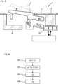
- the figure 1 represents in section a portion of opening 2 of a vehicle. In this case, it is a door of a motor vehicle.
- the invention could also apply to a boot lid of the vehicle.
- the opening 2 has an opening control system 4 with a handle 6, for example external.
- the handle 6 is mounted movable relative to a housing 8, also called a bracket, which is arranged in the thickness of the opening 2.
- the handle 6 is here shown in a position at rest, where it is flush with a body panel 10 specific to opening 2. It is in a first retracted position.
- the outer surface 12 of the opening 2 can be flush with the outer surface 14 of the handle.
- Such a configuration is commonly designated by the Anglo-Saxon term "flush”.
- the handle 6 is pivotally mounted relative to the housing 8, and therefore relative to the opening 2. Alternatively, it could be movable in translation, or follow any other suitable kinematics.
- the handle 6 is articulated using a pivot axis 16 around which it rotates. It can be taken out, and therefore deployed from the opening 2 by projecting from its outer surface 12, or returned to a second retracted position.
- the opening control system 4 comprises an electric motor 18.
- the motor 18 is a rotary electric machine. This motor 18 makes it possible to move the handle 6, for example from the first retracted position to a first position deployed. The motor can also move the handle 6 in the reverse movement to return the handle 6 to the first retracted position, or rest position.
- the motor 18 may comprise a pivoting arm 20, or a connecting rod, pushing the handle 6.
- the system 4 may optionally include return means (not shown), for example a spring, bringing the handle 6 into contact with the arm 20.
- a reduction gear (not shown) makes it possible to reduce the speed of rotation of the rotor of the motor 18 relative to that of the arm 20.
- the system 4 also has a computer 22 controlling the electrical power received by the motor 18.
- the pilot computer 22 may include one or more electrical circuits. It is connected to the master computer 24 of the vehicle, also called the main computer.
- the pilot computer 22 is connected to the vehicle power supply and manages the electrical energy which is converted into mechanical energy by the motor 18 in order to move the handle 6 between the first retracted position and the first deployed position.
- the pilot computer 22 can be placed in the opening 2, for example in the housing 8.
- the motor 18 can also perform the reverse energy conversion. It can convert mechanical energy received into electrical energy generated. It then operates as a voltage generator. For example when the handle 6 is actuated by a user, the motor 18 produces an electrical voltage.
- the motor has an armature and an inductor. Both can be reel sets; for example one of the sets is powered by producing a variable magnetic field, the other receives the variable magnetic field and converts it into voltage.
- the rotor of the motor 18 may have several permanent magnets which create a current in the armature coils, ie a voltage. When a voltage is produced, it is sent to the pilot computer 22.
- the opening control system 4 can comprise a voltage rectifier 26, possibly integrated in the pilot computer 22 or in the motor 18.
- This voltage rectifier 26 makes it possible to transform voltage peaks originating from the motor 18. It can produce a DC voltage or signal in slots.
- the pilot computer 22 can also include a voltage amplifier 28. It amplifies the voltages from the motor 18, and optionally from the voltage rectifier 26. This makes it possible to adapt to the voltage drop linked to the electrical resistance of the electrical circuit of the pilot computer 22.
- the latter may also include an electrical filter 30 making it possible to recognize the cases where the voltage produced by the motor 18 exceeds a threshold S. This verification can be carried out directly at the terminals of the motor 18, or possibly at the amplified voltage level the voltage amplifier 28.
- the pilot computer 22 can be in standby mode and no longer be powered by the vehicle. Its awakening, signifying a switch to active mode, can be triggered by the motor 18 when it produces a voltage greater than the threshold S, also called the wake-up voltage TR.
- the motor comprises a finger exiting and returning linearly into the body of the motor.
- the motor can be a translating magnet in or near a coil. It can also include a capacitor with movable electrodes.
- the figure 2 represents the opening portion 2 of the figure 1 , the pilot computer 22 however being in active mode.
- the handle 6 has been moved to the second retracted position from the first retracted position. It was inserted into the housing 8. By this movement, the motor 18 produced a wake-up voltage TR greater than or equal to the threshold S.
- the threshold S may be greater than or equal to 10mV.
- the threshold S can be of the order of 50mV.
- the threshold S can be chosen to ignore the noise.
- the voltage amplifier 28 can multiply the voltage from the motor 18 by twenty or by one hundred. Therefore, the voltage analyzed by the electric filter 30 can be greater than or equal to 0.5 V.
- the pilot computer 22 since the wake-up voltage TR from the motor 18 has reached or exceeded the threshold S, the pilot computer 22 becomes active.
- the figure 3 shows the opening portion 2 of the figure 1 , the pilot computer 22 however being in active mode.
- the phenomenon is similar to that described in figure 2 , however the handle 6 has been moved in the other direction from the first retracted position of the figure 1 .
- the handle 6 has been pulled into the first deployed position, it comes out of the housing 8. It projects relative to the panel 10, and in particular relative to its outer surface 12.
- the handle 6 can still be pulled into a second deployed position (show in dotted lines). This second position allows to unlock the opening 2 for example.
- the figure 4 sketch a wake-up diagram of a door opening control system.
- the system and the opening may conform to those described in relation to the Figures 1 to 3 .
- the method can be an activation method.
- step (c) activation the pilot computer and the master computer start a communication protocol.
- the pilot computer can send a mode change message via the vehicle's electrical network.
- the master computer can check the presence of the vehicle owner by sending a radio message to a receiving key or an electronic card. In the absence of an appropriate response within a given period, the pilot computer returns to standby mode.
Landscapes
- Power-Operated Mechanisms For Wings (AREA)
- Lock And Its Accessories (AREA)
- Electric Propulsion And Braking For Vehicles (AREA)
Claims (10)
- System zur Steuerung der Öffnung (4) eines zu öffnenden Karosserieteils (2) eines Fahrzeugs, insbesondere einer Fahrzeugtür, wobei das System (4) Folgendes umfasst:- ein Gehäuse (8),- einen in Bezug auf das Gehäuse (8) beweglichen Handgriff (6),- einen Elektromotor (18),- einen Rechner (22), der so konfiguriert ist, dass er vom Standby-Modus in den aktiven Modus umschaltet;
dadurch gekennzeichnet, dass
der Elektromotor (18) so angepasst ist, dass er eine Aufweckspannung TR erzeugt, wenn der Handgriff (6) in Bezug auf das Gehäuse (8) bewegt wird;
wobei der Rechner (22) so konfiguriert ist, dass er vom Bereitschaftsmodus in den aktiven Modus umschaltet, wenn er die vom Motor (18) erzeugte Aufweckspannung TR empfängt. - System (4) nach Anspruch 1, dadurch gekennzeichnet, dass der Rechner (22) so konfiguriert ist, dass er aufwacht, wenn die von dem Motor (18) erzeugte Aufweckspannung TR einen Schwellenwert S überschreitet.
- System (4) nach Anspruch 2, dadurch gekennzeichnet, dass der Schwellenwert S kleiner oder gleich 20 mV oder 5 mV ist.
- System (4) nach einem der Ansprüche 1 bis 3, dadurch gekennzeichnet, dass es einen Gleichrichter (26) für die vom Motor (18) erzeugte Spannung umfasst.
- System (4) nach einem der Ansprüche 1 bis 4, dadurch gekennzeichnet, dass der Rechner (22) einen elektrischen Filter (30) umfasst, der angepasst ist, um die Aufweckspannung TR aus dem Motor (18) zu filtern, und/oder einen Spannungsverstärker (28), der angepasst ist, um die Aufweckspannung TR aus dem Motor (18) zu verstärken.
- System (4) nach einem der Ansprüche 1 bis 5, dadurch gekennzeichnet, dass der Rechner (22) so konfiguriert ist, dass er die Energieversorgung des Motors (18) steuert, um eine mechanische Arbeit auszuführen.
- System (4) nach einem der Ansprüche 1 bis 6, dadurch gekennzeichnet, dass der Motor (18) angepasst ist, um den Handgriff (6) zu bewegen, insbesondere zwischen einer in Bezug auf das Gehäuse (8) eingefahrenen Position und einer ausgefahrenen Position.
- System (4) nach einem der Ansprüche 1 bis 7, dadurch gekennzeichnet, dass der Motor (18) angepasst ist, um eine Aufweckspannung zu erzeugen, wenn der Handgriff (6) zum Gehäuse (8) hin geschoben und/oder von dem Gehäuse (8) weg geschoben wird.
- System (4) nach einem der Ansprüche 1 bis 8, dadurch gekennzeichnet, dass der Motor (18) eine elektromagnetische Spule und einen Permanentmagneten umfasst, die in Bezug zueinander beweglich sind.
- Fahrzeug, insbesondere ein Kraftfahrzeug, umfassend einen zu öffnenden Karosserieteil (2) mit einem Handgriff (6) und ein System (4) zur Steuerung der Öffnung (4) des zu öffnenden Karosserieteils (2), dadurch gekennzeichnet, dass das System (4) einem der Ansprüche 1 bis 9 entspricht, wobei das Fahrzeug einen Hauptrechner (24) umfasst, der mit dem Rechner (22) des Systems zur Steuerung der Öffnung (4) des zu öffnenden Karosserieteils (2) kommuniziert, wenn er aktiv ist.
Applications Claiming Priority (2)
| Application Number | Priority Date | Filing Date | Title |
|---|---|---|---|
| FR1657035A FR3054260B1 (fr) | 2016-07-22 | 2016-07-22 | Systeme de commande d’ouverture d’ouvrant de vehicule automobile |
| PCT/EP2017/064106 WO2018015065A1 (fr) | 2016-07-22 | 2017-06-09 | Systeme de commande d'ouverture d'ouvrant de vehicule automobile |
Publications (2)
| Publication Number | Publication Date |
|---|---|
| EP3488062A1 EP3488062A1 (de) | 2019-05-29 |
| EP3488062B1 true EP3488062B1 (de) | 2020-04-15 |
Family
ID=57396577
Family Applications (1)
| Application Number | Title | Priority Date | Filing Date |
|---|---|---|---|
| EP17727930.4A Active EP3488062B1 (de) | 2016-07-22 | 2017-06-09 | System zur steuerung der öffnung eines zu öffnenden karosserieteils eines kraftfahrzeuges |
Country Status (5)
| Country | Link |
|---|---|
| US (1) | US10487547B2 (de) |
| EP (1) | EP3488062B1 (de) |
| CN (1) | CN109790731B (de) |
| FR (1) | FR3054260B1 (de) |
| WO (1) | WO2018015065A1 (de) |
Families Citing this family (21)
| Publication number | Priority date | Publication date | Assignee | Title |
|---|---|---|---|---|
| DE102013112705A1 (de) * | 2013-11-18 | 2015-05-21 | Illinois Tool Works Inc. | System aus einem Bauteil und einer Betätigungsvorrichtung für das Bauteil |
| FR3054260B1 (fr) * | 2016-07-22 | 2018-07-13 | Peugeot Citroen Automobiles Sa | Systeme de commande d’ouverture d’ouvrant de vehicule automobile |
| US10738513B2 (en) * | 2016-12-09 | 2020-08-11 | Toyota Motor Engineering & Manufacturing North America, Inc. | Flush power slide door handle |
| CN109958348B (zh) * | 2017-12-25 | 2022-01-28 | 伊利诺斯工具制品有限公司 | 一种隐藏式的把手总成 |
| EP3540157A1 (de) | 2018-03-16 | 2019-09-18 | Akwel Vigo Spain SL | Linearaktor öffnungskontrolle für kraftfahrzeuge |
| FR3078990B1 (fr) * | 2018-03-16 | 2021-01-15 | Mgi Coutier Espana Sl | Commande d'ouverture a remontage mecanique |
| FR3079258B1 (fr) | 2018-03-21 | 2022-06-17 | Mgi Coutier Espana Sl | Commande d'ouverture a deverrouillage mecanique de secours |
| FR3090719B1 (fr) * | 2018-12-20 | 2021-01-22 | Mgi Coutier Espana | Commande d’ouverture à remontage mécanique. |
| FR3093750B1 (fr) * | 2019-03-12 | 2022-12-16 | U Shin Italia Spa | Poignée d’ouvrant pour véhicule automobile |
| JP7099401B2 (ja) | 2019-05-08 | 2022-07-12 | トヨタ自動車株式会社 | 車両ドア構造 |
| DE102020209488A1 (de) | 2019-09-06 | 2021-03-11 | Witte Automotive Gmbh | Türgriffanordnung mit einem Verstellmechanismus für einen Türgriff |
| WO2021075301A1 (ja) * | 2019-10-16 | 2021-04-22 | 株式会社ユーシン | ドア開閉検出装置及びドア開閉装置 |
| EP3835519B1 (de) * | 2019-12-09 | 2022-05-18 | U-Shin Italia S.p.A. | Motorisierter türrahmengriff für ein kraftfahrzeug |
| DE102020104846A1 (de) * | 2020-02-25 | 2021-08-26 | Brose Fahrzeugteile Se & Co. Kommanditgesellschaft, Bamberg | Verfahren zum Betrieb eines Kraftfahrzeugschließsystems |
| CN113863796B (zh) * | 2020-06-30 | 2022-08-09 | 比亚迪股份有限公司 | 门把手装置以及具有其的车辆 |
| DE102021205153A1 (de) * | 2021-05-20 | 2022-11-24 | Hs Products Engineering Gmbh | Elektrischer Türgriff für eine Fahrzeugtür |
| DE102021214163A1 (de) * | 2021-12-10 | 2023-06-15 | Witte Automotive Gmbh | Fahrzeugtür mit einer Griffanordnung und Fahrzeug |
| EP4234858B1 (de) * | 2022-02-23 | 2025-04-09 | Minebea AccessSolutions Italia S.p.A. | Fahrzeugtürgriffanordnung |
| JP7818149B2 (ja) * | 2022-06-21 | 2026-02-20 | サカエ理研工業株式会社 | 車両用ドアハンドル装置 |
| US20240229520A9 (en) * | 2022-10-24 | 2024-07-11 | Magna Mirrors Of America, Inc. | Vehicular door handle assembly with protruding handle portion |
| US20250215731A1 (en) * | 2023-12-28 | 2025-07-03 | Sl Corporation | Door handle for vehicle |
Family Cites Families (43)
| Publication number | Priority date | Publication date | Assignee | Title |
|---|---|---|---|---|
| EP0808977B1 (de) * | 1996-05-21 | 2000-08-16 | Robert Bosch Gmbh | Verfahren zur Ansteuerung eines elektrisch betätigten Kraftfahrzeug-Türschlosses od. dgl. |
| FR2750155B1 (fr) * | 1996-06-25 | 1998-09-04 | Valeo Securite Habitacle | Dispositif de commande de l'ouverture d'une serrure d'un ouvrant de vehicule automobile |
| DE19935290B4 (de) * | 1999-07-27 | 2007-04-05 | Huf Hülsbeck & Fürst Gmbh & Co. Kg | Türaußengriff, insbesondere für Fahrzeuge |
| GB2361675B (en) * | 2000-04-26 | 2002-12-31 | Meritor Light Vehicle Sys Ltd | Passenger door |
| JP2005080444A (ja) * | 2003-09-02 | 2005-03-24 | Omron Corp | 制御装置 |
| JP3987976B2 (ja) * | 2003-11-25 | 2007-10-10 | 自動車電機工業株式会社 | バックドア自動開閉装置 |
| WO2007121817A1 (fr) * | 2006-04-13 | 2007-11-01 | Continental Automotive France | Dispositif de detection de mouvement d’une poignee de portiere de vehicule automobile |
| JP2010008856A (ja) * | 2008-06-30 | 2010-01-14 | Olympus Corp | 顕微鏡撮像装置及び顕微鏡撮像システム |
| US8786401B2 (en) * | 2009-12-23 | 2014-07-22 | Magna Mirrors Of America, Inc. | Extendable flush door handle for vehicle |
| JP5296716B2 (ja) * | 2010-01-15 | 2013-09-25 | 株式会社東海理化電機製作所 | 車両のドアロック装置 |
| CN102096956B (zh) * | 2010-11-15 | 2013-02-06 | 王翔 | 汽车无钥匙远程控制系统的数据处理方法 |
| DE102011009524B4 (de) * | 2011-01-26 | 2014-02-27 | Audi Ag | Türgriffanordnung für ein Fahrzeug |
| DE102011018875A1 (de) * | 2011-04-28 | 2012-10-31 | Audi Ag | Bedieneinrichtung zur Steuerung des Betriebs eines einen Elektromotor umfassenden Kraftfahrzeugs und Kraftfahrzeug |
| US9303442B2 (en) * | 2011-06-21 | 2016-04-05 | GM Global Technology Operations LLC | Passive verification of operator presence in handling requests for vehicle features |
| US9103143B2 (en) * | 2011-09-26 | 2015-08-11 | Tesla Motors, Inc. | Door handle apparatus for vehicles |
| US9151089B2 (en) * | 2011-09-26 | 2015-10-06 | Tesla Motors, Inc. | Controller apparatus and sensors for a vehicle door handle |
| US8690204B2 (en) * | 2011-11-23 | 2014-04-08 | GM Global Technology Operations LLC | Flush door handle assembly with normal deployment |
| US8443553B1 (en) * | 2011-11-23 | 2013-05-21 | GM Global Technology Operations LLC | Closure assembly with moveable cover and closeout for a retractable handle |
| EP2784249B1 (de) * | 2011-11-25 | 2018-02-14 | Mitsubishi Electric Corporation | Fahrzeugmontiertes kommunikationssystem, mobile vorrichtung, kommunikationssystem und kommunikationsverfahren |
| FR2996081B1 (fr) * | 2012-09-21 | 2015-08-21 | Continental Automotive France | Dispositif de maintien dans un mode de veille et de commutation dans un mode actif d'un calculateur de vehicule automobile comportant un microprocesseur |
| DE102012023792A1 (de) * | 2012-12-05 | 2014-06-05 | GM Global Technology Operations LLC (n. d. Ges. d. Staates Delaware) | Türschließsystem |
| US8918249B2 (en) * | 2013-03-15 | 2014-12-23 | GM Global Technology Operations LLC | Dual function electronic control unit |
| CN103366432A (zh) * | 2013-06-26 | 2013-10-23 | 瑞安市峰达汽车部件有限公司 | 一种pke上的门把手感应系统 |
| CN103386935B (zh) * | 2013-07-25 | 2016-03-02 | 株洲南车时代电气股份有限公司 | 一种整车控制方法与整车控制器 |
| DE102013112120A1 (de) * | 2013-11-04 | 2015-05-07 | Kiekert Aktiengesellschaft | Kraftfahrzeugtürverschluss |
| DE102013112705A1 (de) * | 2013-11-18 | 2015-05-21 | Illinois Tool Works Inc. | System aus einem Bauteil und einer Betätigungsvorrichtung für das Bauteil |
| US10563437B2 (en) * | 2014-09-18 | 2020-02-18 | Huf Hülsbeck & Fürst Gmbh & Co. Kg | Flush comfort handle |
| DE102014114799A1 (de) * | 2014-10-13 | 2016-04-14 | Huf Hülsbeck & Fürst Gmbh & Co. Kg | Betätigungshandhabe für ein Kraftfahrzeug |
| EP3020895B1 (de) * | 2014-11-13 | 2017-11-15 | Huf Hülsbeck & Fürst GmbH & Co. KG | Türgriff eines fahrzeugs mit einem zugmittel |
| JP2016142045A (ja) * | 2015-02-02 | 2016-08-08 | アイシン精機株式会社 | 開閉体開閉装置 |
| EP3274532B1 (de) * | 2015-03-25 | 2021-06-30 | Jaguar Land Rover Limited | Einziehbare griffanordnung |
| GB2536672B (en) * | 2015-03-25 | 2018-04-04 | Jaguar Land Rover Ltd | Rectractable handle arrangement with emergency manual deployment |
| US10927573B2 (en) * | 2015-06-08 | 2021-02-23 | Illinois Tool Works Inc. | Door lock operator having different types of door lock operation |
| EP3106594A1 (de) * | 2015-06-16 | 2016-12-21 | U-Shin Italia S.p.A. | Handgriff für eine fahrzeugtür |
| FR3051501B1 (fr) * | 2016-05-20 | 2018-05-18 | Peugeot Citroen Automobiles Sa | Commande d’ouverture exterieure de vehicule automobile |
| US10590677B2 (en) * | 2016-06-28 | 2020-03-17 | Ford Global Technologies, Llc | Heated mechanism for deployable exterior door handle for a vehicle |
| FR3054260B1 (fr) * | 2016-07-22 | 2018-07-13 | Peugeot Citroen Automobiles Sa | Systeme de commande d’ouverture d’ouvrant de vehicule automobile |
| WO2018036868A1 (de) * | 2016-08-23 | 2018-03-01 | Huf Hülsbeck & Fürst Gmbh & Co. Kg | Erfassungssystem zur detektion einer betätigung bei einer griffvorrichtung eines fahrzeuges |
| JP7128110B2 (ja) * | 2016-08-23 | 2022-08-31 | 株式会社アルファ | 車両用ドアアウトサイドハンドル装置、車両用ドア及び車両 |
| FR3060630B1 (fr) * | 2016-12-20 | 2019-11-22 | Akwel | Commande d'ouverture affleurante a ejection et retraction mecanique ou electrique. |
| US10385594B2 (en) * | 2017-03-06 | 2019-08-20 | Trimark Corporation | Power locking door handle with capacitive sensing |
| JP6907797B2 (ja) * | 2017-08-09 | 2021-07-21 | トヨタ自動車株式会社 | 車両用ドア開閉制御装置 |
| JP7028627B2 (ja) * | 2017-12-19 | 2022-03-02 | マツダ株式会社 | 車両用ドアロック装置、及び、その取付方法 |
-
2016
- 2016-07-22 FR FR1657035A patent/FR3054260B1/fr not_active Expired - Fee Related
-
2017
- 2017-06-09 CN CN201780041085.XA patent/CN109790731B/zh active Active
- 2017-06-09 EP EP17727930.4A patent/EP3488062B1/de active Active
- 2017-06-09 US US16/318,677 patent/US10487547B2/en active Active
- 2017-06-09 WO PCT/EP2017/064106 patent/WO2018015065A1/fr not_active Ceased
Non-Patent Citations (1)
| Title |
|---|
| None * |
Also Published As
| Publication number | Publication date |
|---|---|
| US20190284847A1 (en) | 2019-09-19 |
| FR3054260B1 (fr) | 2018-07-13 |
| EP3488062A1 (de) | 2019-05-29 |
| CN109790731B (zh) | 2021-01-12 |
| CN109790731A (zh) | 2019-05-21 |
| FR3054260A1 (fr) | 2018-01-26 |
| US10487547B2 (en) | 2019-11-26 |
| WO2018015065A1 (fr) | 2018-01-25 |
Similar Documents
| Publication | Publication Date | Title |
|---|---|---|
| WO2018015065A1 (fr) | Systeme de commande d'ouverture d'ouvrant de vehicule automobile | |
| FR2817275A1 (fr) | Unite de commande de serrure de portiere | |
| EP1844231B1 (de) | Vorrichtung zur steuerung eines wärmekraftmaschinenanlassers, wie etwa der eines kraftfahrzeuges, und anlasser mit solch einer vorrichtung | |
| EP4112855B1 (de) | Verfahren zum auswerfen eines flush-griffs unter frostbedingungen | |
| FR3071001A1 (fr) | Dispositif de tele-alimentation repeteur de communication sans contact pour une poignee de porte de vehicule automobile | |
| FR2477762A1 (fr) | Agencement de commutation pour dispositif de fermeture a commande centrale et a protection antivol destine aux portes de vehicules automobiles | |
| EP3011642B1 (de) | Steckdosenbaugruppe | |
| EP1041277B1 (de) | Anlasser-Regelvorrichtung für Kraftfahrzeuge zur Verhinderung von Verschleiss | |
| FR2460562A1 (fr) | Dispositif electrique de commande centralise, notamment pour serrures de vehicule automobile | |
| EP2652719A1 (de) | Elektronisches kommunikationsmodul zum verriegeln/entriegeln einer beweglichen platte eines kraftfahrzeugs, entsprechende cpu und freihand-zugangssystem | |
| EP2239455A1 (de) | Anlassvorrichtung für Verbrennungsmotor, insbesondere von Kraftfahrzeugen | |
| EP1058785A1 (de) | Steuervorrichtung für anlasser eines kraftfahrzeuges | |
| WO1991008133A1 (fr) | Dispositif de commande du frein de parc pour un vehicule automobile | |
| FR3125553A1 (fr) | Procédé et dispositif de commande d’un moteur électrique d’un système d’ouverture/fermeture motorisé d’un hayon d’un véhicule | |
| FR2918028A1 (fr) | Dispositif de restitution d'effort | |
| FR2930001A1 (fr) | Dispositif de demarrage pour moteur a combustion interne, notamment de vehicule automobile. | |
| FR2809132A1 (fr) | Vehicule automobile equipe d'un systeme de detection de presence d'utilisateur | |
| EP2353446B1 (de) | Automatisches Aktivierungssystem und Aktivierungverfahren von Möbelschubladen, und Möbelstück, das mit einem solchen System ausgestattet ist | |
| FR2792416A1 (fr) | Procede de controle de la fin de course d'un organe mobile et dispositif pour sa mise en oeuvre | |
| FR2741651A1 (fr) | Dispositif assurant l'arret automatique et la synchronisation de volets battants motorises a l'ouverture et a la fermeture | |
| FR1408972A (fr) | Perfectionnements aux véhicules électriques à accumulateurs | |
| FR2859324A1 (fr) | Entrainement de reglage avec unite de commande et procede pour faire fonctionner l'entrainement de reglage | |
| EP1788464B1 (de) | Konfigurationsgerät für Gebäudeaktuatoren | |
| EP1056620A1 (de) | Verfahren und vorrichtung zum beheizen eines rückblickspiegels eines kraftfahrzeuges | |
| FR2877488A1 (fr) | Relais pour appareil electrique en courant continu |
Legal Events
| Date | Code | Title | Description |
|---|---|---|---|
| STAA | Information on the status of an ep patent application or granted ep patent |
Free format text: STATUS: UNKNOWN |
|
| STAA | Information on the status of an ep patent application or granted ep patent |
Free format text: STATUS: THE INTERNATIONAL PUBLICATION HAS BEEN MADE |
|
| PUAI | Public reference made under article 153(3) epc to a published international application that has entered the european phase |
Free format text: ORIGINAL CODE: 0009012 |
|
| STAA | Information on the status of an ep patent application or granted ep patent |
Free format text: STATUS: REQUEST FOR EXAMINATION WAS MADE |
|
| 17P | Request for examination filed |
Effective date: 20181218 |
|
| AK | Designated contracting states |
Kind code of ref document: A1 Designated state(s): AL AT BE BG CH CY CZ DE DK EE ES FI FR GB GR HR HU IE IS IT LI LT LU LV MC MK MT NL NO PL PT RO RS SE SI SK SM TR |
|
| AX | Request for extension of the european patent |
Extension state: BA ME |
|
| DAV | Request for validation of the european patent (deleted) | ||
| DAX | Request for extension of the european patent (deleted) | ||
| GRAJ | Information related to disapproval of communication of intention to grant by the applicant or resumption of examination proceedings by the epo deleted |
Free format text: ORIGINAL CODE: EPIDOSDIGR1 |
|
| STAA | Information on the status of an ep patent application or granted ep patent |
Free format text: STATUS: GRANT OF PATENT IS INTENDED |
|
| GRAP | Despatch of communication of intention to grant a patent |
Free format text: ORIGINAL CODE: EPIDOSNIGR1 |
|
| INTG | Intention to grant announced |
Effective date: 20191111 |
|
| GRAS | Grant fee paid |
Free format text: ORIGINAL CODE: EPIDOSNIGR3 |
|
| GRAA | (expected) grant |
Free format text: ORIGINAL CODE: 0009210 |
|
| STAA | Information on the status of an ep patent application or granted ep patent |
Free format text: STATUS: THE PATENT HAS BEEN GRANTED |
|
| AK | Designated contracting states |
Kind code of ref document: B1 Designated state(s): AL AT BE BG CH CY CZ DE DK EE ES FI FR GB GR HR HU IE IS IT LI LT LU LV MC MK MT NL NO PL PT RO RS SE SI SK SM TR |
|
| REG | Reference to a national code |
Ref country code: CH Ref legal event code: EP |
|
| REG | Reference to a national code |
Ref country code: DE Ref legal event code: R096 Ref document number: 602017014841 Country of ref document: DE |
|
| REG | Reference to a national code |
Ref country code: IE Ref legal event code: FG4D Free format text: LANGUAGE OF EP DOCUMENT: FRENCH |
|
| REG | Reference to a national code |
Ref country code: AT Ref legal event code: REF Ref document number: 1257471 Country of ref document: AT Kind code of ref document: T Effective date: 20200515 |
|
| REG | Reference to a national code |
Ref country code: NL Ref legal event code: MP Effective date: 20200415 |
|
| REG | Reference to a national code |
Ref country code: LT Ref legal event code: MG4D |
|
| PG25 | Lapsed in a contracting state [announced via postgrant information from national office to epo] |
Ref country code: NL Free format text: LAPSE BECAUSE OF FAILURE TO SUBMIT A TRANSLATION OF THE DESCRIPTION OR TO PAY THE FEE WITHIN THE PRESCRIBED TIME-LIMIT Effective date: 20200415 Ref country code: PT Free format text: LAPSE BECAUSE OF FAILURE TO SUBMIT A TRANSLATION OF THE DESCRIPTION OR TO PAY THE FEE WITHIN THE PRESCRIBED TIME-LIMIT Effective date: 20200817 Ref country code: LT Free format text: LAPSE BECAUSE OF FAILURE TO SUBMIT A TRANSLATION OF THE DESCRIPTION OR TO PAY THE FEE WITHIN THE PRESCRIBED TIME-LIMIT Effective date: 20200415 Ref country code: FI Free format text: LAPSE BECAUSE OF FAILURE TO SUBMIT A TRANSLATION OF THE DESCRIPTION OR TO PAY THE FEE WITHIN THE PRESCRIBED TIME-LIMIT Effective date: 20200415 Ref country code: SE Free format text: LAPSE BECAUSE OF FAILURE TO SUBMIT A TRANSLATION OF THE DESCRIPTION OR TO PAY THE FEE WITHIN THE PRESCRIBED TIME-LIMIT Effective date: 20200415 Ref country code: GR Free format text: LAPSE BECAUSE OF FAILURE TO SUBMIT A TRANSLATION OF THE DESCRIPTION OR TO PAY THE FEE WITHIN THE PRESCRIBED TIME-LIMIT Effective date: 20200716 Ref country code: IS Free format text: LAPSE BECAUSE OF FAILURE TO SUBMIT A TRANSLATION OF THE DESCRIPTION OR TO PAY THE FEE WITHIN THE PRESCRIBED TIME-LIMIT Effective date: 20200815 Ref country code: NO Free format text: LAPSE BECAUSE OF FAILURE TO SUBMIT A TRANSLATION OF THE DESCRIPTION OR TO PAY THE FEE WITHIN THE PRESCRIBED TIME-LIMIT Effective date: 20200715 |
|
| RAP2 | Party data changed (patent owner data changed or rights of a patent transferred) |
Owner name: U-SHIN DEUTSCHLAND ZUGANGSSYSTEME GMBH Owner name: PSA AUTOMOBILES SA |
|
| REG | Reference to a national code |
Ref country code: AT Ref legal event code: MK05 Ref document number: 1257471 Country of ref document: AT Kind code of ref document: T Effective date: 20200415 |
|
| PG25 | Lapsed in a contracting state [announced via postgrant information from national office to epo] |
Ref country code: BG Free format text: LAPSE BECAUSE OF FAILURE TO SUBMIT A TRANSLATION OF THE DESCRIPTION OR TO PAY THE FEE WITHIN THE PRESCRIBED TIME-LIMIT Effective date: 20200715 Ref country code: RS Free format text: LAPSE BECAUSE OF FAILURE TO SUBMIT A TRANSLATION OF THE DESCRIPTION OR TO PAY THE FEE WITHIN THE PRESCRIBED TIME-LIMIT Effective date: 20200415 Ref country code: HR Free format text: LAPSE BECAUSE OF FAILURE TO SUBMIT A TRANSLATION OF THE DESCRIPTION OR TO PAY THE FEE WITHIN THE PRESCRIBED TIME-LIMIT Effective date: 20200415 Ref country code: LV Free format text: LAPSE BECAUSE OF FAILURE TO SUBMIT A TRANSLATION OF THE DESCRIPTION OR TO PAY THE FEE WITHIN THE PRESCRIBED TIME-LIMIT Effective date: 20200415 |
|
| PG25 | Lapsed in a contracting state [announced via postgrant information from national office to epo] |
Ref country code: AL Free format text: LAPSE BECAUSE OF FAILURE TO SUBMIT A TRANSLATION OF THE DESCRIPTION OR TO PAY THE FEE WITHIN THE PRESCRIBED TIME-LIMIT Effective date: 20200415 |
|
| REG | Reference to a national code |
Ref country code: DE Ref legal event code: R097 Ref document number: 602017014841 Country of ref document: DE |
|
| PG25 | Lapsed in a contracting state [announced via postgrant information from national office to epo] |
Ref country code: SM Free format text: LAPSE BECAUSE OF FAILURE TO SUBMIT A TRANSLATION OF THE DESCRIPTION OR TO PAY THE FEE WITHIN THE PRESCRIBED TIME-LIMIT Effective date: 20200415 Ref country code: EE Free format text: LAPSE BECAUSE OF FAILURE TO SUBMIT A TRANSLATION OF THE DESCRIPTION OR TO PAY THE FEE WITHIN THE PRESCRIBED TIME-LIMIT Effective date: 20200415 Ref country code: RO Free format text: LAPSE BECAUSE OF FAILURE TO SUBMIT A TRANSLATION OF THE DESCRIPTION OR TO PAY THE FEE WITHIN THE PRESCRIBED TIME-LIMIT Effective date: 20200415 Ref country code: AT Free format text: LAPSE BECAUSE OF FAILURE TO SUBMIT A TRANSLATION OF THE DESCRIPTION OR TO PAY THE FEE WITHIN THE PRESCRIBED TIME-LIMIT Effective date: 20200415 Ref country code: ES Free format text: LAPSE BECAUSE OF FAILURE TO SUBMIT A TRANSLATION OF THE DESCRIPTION OR TO PAY THE FEE WITHIN THE PRESCRIBED TIME-LIMIT Effective date: 20200415 Ref country code: CZ Free format text: LAPSE BECAUSE OF FAILURE TO SUBMIT A TRANSLATION OF THE DESCRIPTION OR TO PAY THE FEE WITHIN THE PRESCRIBED TIME-LIMIT Effective date: 20200415 Ref country code: DK Free format text: LAPSE BECAUSE OF FAILURE TO SUBMIT A TRANSLATION OF THE DESCRIPTION OR TO PAY THE FEE WITHIN THE PRESCRIBED TIME-LIMIT Effective date: 20200415 Ref country code: MC Free format text: LAPSE BECAUSE OF FAILURE TO SUBMIT A TRANSLATION OF THE DESCRIPTION OR TO PAY THE FEE WITHIN THE PRESCRIBED TIME-LIMIT Effective date: 20200415 |
|
| REG | Reference to a national code |
Ref country code: CH Ref legal event code: PL |
|
| PLBE | No opposition filed within time limit |
Free format text: ORIGINAL CODE: 0009261 |
|
| STAA | Information on the status of an ep patent application or granted ep patent |
Free format text: STATUS: NO OPPOSITION FILED WITHIN TIME LIMIT |
|
| PG25 | Lapsed in a contracting state [announced via postgrant information from national office to epo] |
Ref country code: PL Free format text: LAPSE BECAUSE OF FAILURE TO SUBMIT A TRANSLATION OF THE DESCRIPTION OR TO PAY THE FEE WITHIN THE PRESCRIBED TIME-LIMIT Effective date: 20200415 Ref country code: SK Free format text: LAPSE BECAUSE OF FAILURE TO SUBMIT A TRANSLATION OF THE DESCRIPTION OR TO PAY THE FEE WITHIN THE PRESCRIBED TIME-LIMIT Effective date: 20200415 |
|
| 26N | No opposition filed |
Effective date: 20210118 |
|
| PG25 | Lapsed in a contracting state [announced via postgrant information from national office to epo] |
Ref country code: LU Free format text: LAPSE BECAUSE OF NON-PAYMENT OF DUE FEES Effective date: 20200609 |
|
| REG | Reference to a national code |
Ref country code: BE Ref legal event code: MM Effective date: 20200630 |
|
| PG25 | Lapsed in a contracting state [announced via postgrant information from national office to epo] |
Ref country code: LI Free format text: LAPSE BECAUSE OF NON-PAYMENT OF DUE FEES Effective date: 20200630 Ref country code: CH Free format text: LAPSE BECAUSE OF NON-PAYMENT OF DUE FEES Effective date: 20200630 Ref country code: IE Free format text: LAPSE BECAUSE OF NON-PAYMENT OF DUE FEES Effective date: 20200609 |
|
| PG25 | Lapsed in a contracting state [announced via postgrant information from national office to epo] |
Ref country code: SI Free format text: LAPSE BECAUSE OF FAILURE TO SUBMIT A TRANSLATION OF THE DESCRIPTION OR TO PAY THE FEE WITHIN THE PRESCRIBED TIME-LIMIT Effective date: 20200415 Ref country code: BE Free format text: LAPSE BECAUSE OF NON-PAYMENT OF DUE FEES Effective date: 20200630 |
|
| PG25 | Lapsed in a contracting state [announced via postgrant information from national office to epo] |
Ref country code: TR Free format text: LAPSE BECAUSE OF FAILURE TO SUBMIT A TRANSLATION OF THE DESCRIPTION OR TO PAY THE FEE WITHIN THE PRESCRIBED TIME-LIMIT Effective date: 20200415 Ref country code: MT Free format text: LAPSE BECAUSE OF FAILURE TO SUBMIT A TRANSLATION OF THE DESCRIPTION OR TO PAY THE FEE WITHIN THE PRESCRIBED TIME-LIMIT Effective date: 20200415 Ref country code: CY Free format text: LAPSE BECAUSE OF FAILURE TO SUBMIT A TRANSLATION OF THE DESCRIPTION OR TO PAY THE FEE WITHIN THE PRESCRIBED TIME-LIMIT Effective date: 20200415 |
|
| PG25 | Lapsed in a contracting state [announced via postgrant information from national office to epo] |
Ref country code: MK Free format text: LAPSE BECAUSE OF FAILURE TO SUBMIT A TRANSLATION OF THE DESCRIPTION OR TO PAY THE FEE WITHIN THE PRESCRIBED TIME-LIMIT Effective date: 20200415 |
|
| PGFP | Annual fee paid to national office [announced via postgrant information from national office to epo] |
Ref country code: DE Payment date: 20250520 Year of fee payment: 9 |
|
| PGFP | Annual fee paid to national office [announced via postgrant information from national office to epo] |
Ref country code: GB Payment date: 20250520 Year of fee payment: 9 |
|
| PGFP | Annual fee paid to national office [announced via postgrant information from national office to epo] |
Ref country code: IT Payment date: 20250520 Year of fee payment: 9 |
|
| PGFP | Annual fee paid to national office [announced via postgrant information from national office to epo] |
Ref country code: FR Payment date: 20250520 Year of fee payment: 9 |